WO2020045032A1 - 締結構造 - Google Patents
締結構造 Download PDFInfo
- Publication number
- WO2020045032A1 WO2020045032A1 PCT/JP2019/031376 JP2019031376W WO2020045032A1 WO 2020045032 A1 WO2020045032 A1 WO 2020045032A1 JP 2019031376 W JP2019031376 W JP 2019031376W WO 2020045032 A1 WO2020045032 A1 WO 2020045032A1
- Authority
- WO
- WIPO (PCT)
- Prior art keywords
- fastening
- hole
- roof panel
- nut
- outer diameter
- Prior art date
- Legal status (The legal status is an assumption and is not a legal conclusion. Google has not performed a legal analysis and makes no representation as to the accuracy of the status listed.)
- Ceased
Links
Images

Classifications
-
- B—PERFORMING OPERATIONS; TRANSPORTING
- B62—LAND VEHICLES FOR TRAVELLING OTHERWISE THAN ON RAILS
- B62D—MOTOR VEHICLES; TRAILERS
- B62D25/00—Superstructure or monocoque structure sub-units; Parts or details thereof not otherwise provided for
- B62D25/08—Front or rear portions
-
- F—MECHANICAL ENGINEERING; LIGHTING; HEATING; WEAPONS; BLASTING
- F16—ENGINEERING ELEMENTS AND UNITS; GENERAL MEASURES FOR PRODUCING AND MAINTAINING EFFECTIVE FUNCTIONING OF MACHINES OR INSTALLATIONS; THERMAL INSULATION IN GENERAL
- F16B—DEVICES FOR FASTENING OR SECURING CONSTRUCTIONAL ELEMENTS OR MACHINE PARTS TOGETHER, e.g. NAILS, BOLTS, CIRCLIPS, CLAMPS, CLIPS OR WEDGES; JOINTS OR JOINTING
- F16B5/00—Joining sheets or plates, e.g. panels, to one another or to strips or bars parallel to them
- F16B5/02—Joining sheets or plates, e.g. panels, to one another or to strips or bars parallel to them by means of fastening members using screw-thread
Definitions
- the present disclosure relates to a fastening structure provided in a vehicle.
- Patent Literature 1 discloses a structure in which an exterior component (air deflector) is fastened to a tailgate panel.
- the member when manufacturing a member to be fastened using a bolt, a dimensional error may occur in the member.
- the member when fastening the member, there is a problem that it becomes difficult to insert a bolt into a hole formed in the member.
- the member in consideration of a dimensional error occurring at the time of manufacturing a member to be fastened, the member may be formed with a hole larger than the outer diameter of the bolt. In this case, since a gap is formed between the outer surface of the bolt and the inner surface of the hole formed in the member, there is a problem that the sealing performance is deteriorated.
- a roof panel and a tailgate are connected via a hinge.
- a bolt having a fastening portion extending downward is inserted into the hole formed in the hinge and the hole formed in the roof panel from above, and the roof panel and the hinge are inserted below the roof panel, that is, the vehicle.
- Fasten with a nut from inside there has been a problem that it is difficult to tighten the nut from below the roof panel.
- an object of the present disclosure is to provide a fastening structure that facilitates assembly work, allows dimensional errors of members, and improves sealability. I do.
- a pedestal portion a first fastening portion extending upward perpendicular to the pedestal portion, and a second fastening portion extending downward orthogonal to the pedestal portion are provided.
- a fastening member, a mounting member provided at an upper portion of the pedestal portion and having a hole into which the first fastening portion is inserted, and a mounting member provided at an upper portion of the mounting member, and the first fastening portion A first nut fastened to the vehicle, a vehicle roof panel having a hole provided at a lower portion of the pedestal portion and having the second fastening portion inserted therein, and a first nut provided at a lower portion of the pedestal portion.
- a sealing member provided between an outer side surface of the second fastening portion and an inner side surface of the hole of the roof panel; and a second fastening portion provided at a lower portion of the roof panel. And a second nut fastened to the fastening structure To provide.
- the inner diameter of the hole of the mounting member may be larger than the outer diameter of the first fastening portion, and smaller than the outer diameter of the pedestal portion and the outer diameter of the first nut. Further, the inside diameter of the hole of the roof panel may be larger than the outside diameter of the second fastening portion, and may be smaller than the outside diameter of the pedestal portion and the outside diameter of the second nut.
- an inner diameter of the holes of the plurality of plates may be larger than an outer diameter of the second fastening portion, and smaller than an outer diameter of the pedestal portion and an outer diameter of the second nut.
- the mounting member may movably couple a tailgate of the vehicle to the roof panel. Further, the second nut may be welded to a member that contacts an upper surface of the second nut.
- the fastening structure there is an effect that the assembling work becomes easy, the dimensional error of the member is allowed, and the sealing property is improved.
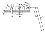
- FIG. 1 shows a state of a vehicle provided with a fastening structure according to the present embodiment.
- FIG. 2 is an enlarged view of a region A in FIG.
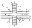
- FIG. 3 is an enlarged view of a region B in FIG.
- FIG. 1 is a diagram illustrating a state of a vehicle provided with a fastening structure 1 according to the present embodiment.
- FIG. 2 is an enlarged view of a region A in FIG.
- FIG. 3 is an enlarged view of a region B in FIG.
- the vehicle is, for example, an SUV (Sport ⁇ Utility ⁇ Vehicle).
- the vehicle has a fastening structure 1.
- the fastening structure 1 is a structure in which a mounting member 13 for movably connecting a tailgate 12 to the roof panel 11 is fastened to a roof panel 11 of the vehicle.
- the fastening structure 1 includes a roof panel 11, a tailgate 12, a mounting member 13, a fastening member 14, a first nut 15, a side panel 16, a first reinforcing member 17, a second reinforcing member 18, a sealing member 19, and a second nut. 20.
- the roof panel 11 is a plate that forms the ceiling of the vehicle.
- the roof panel 11 extends on a plane substantially perpendicular to the height direction of the vehicle.
- the tailgate 12 is a plate-shaped door member provided rearward in the front-rear direction of the vehicle.
- the tailgate 12 is provided movably with respect to the roof panel 11. Specifically, the upper end of the tailgate 12 in the vehicle height direction is coupled to the rear end of the roof panel 11 in the vehicle front-rear direction via a mounting member 13.
- the tailgate 12 is rotatable with respect to the roof panel 11 with the vicinity of the upper end of the tailgate 12 in the vehicle height direction as a fulcrum.
- the roof panel 11 has a plurality of holes 111.
- the plurality of holes 111 are holes for inserting some members of the fastening member 14. Details of the hole 111 will be described later.
- the attachment member 13 is a member that movably couples the tailgate 12 to the roof panel 11.
- the attachment member 13 is, for example, a hinge.
- the mounting member 13 has a fixed portion 131, a movable portion 132, and a shaft portion 133.
- the fixing part 131 is fixed to the roof panel 11.
- the fixing portion 131 is fixed to the roof panel 11 by a plurality of fastening members 14, a plurality of first nuts 15, and a plurality of second nuts 20.
- the mounting member 13 has a plurality of holes 1311.
- the fixing portion 131 has a plurality of holes 1311.
- the plurality of holes 1311 are holes into which some members of the fastening member 14 are inserted. The details of the hole 1311 will be described later.
- the movable part 132 is rotatable about the shaft part 133 with respect to the fixed part 131.
- the shaft portion 133 is inserted into a hole formed near the front end of the movable portion 132 in the front-rear direction of the vehicle and a hole formed near the rear end of the fixed portion 131 in the front-rear direction of the vehicle.
- the shaft 133 has, for example, a cylindrical shape.
- the movable portion 132 is fixed to the vicinity of the upper end of the tailgate 12 in the vehicle height direction by a fastening member (not shown).
- the fastening member 14 is a member for fastening the roof panel 11 and the mounting member 13.
- the fastening member 14 has a pedestal part 141, a first fastening part 142, and a second fastening part 143.
- the pedestal portion 141 is formed orthogonal to the longitudinal direction of the fastening member 14 and substantially at the center in the longitudinal direction of the fastening member 14.
- the base 141 has, for example, a columnar shape.
- the outer diameter of the pedestal part 141 is larger than the outer diameter of the first fastening part 142 and that of the second fastening part 143.
- the radial center of the pedestal portion 141 is coaxial with the radial center of the first fastening portion 142 and the radial center of the second fastening portion 143.
- the first fastening portion 142 extends perpendicularly to the pedestal portion 141 and extends outside the vehicle, that is, upward in the height direction of the vehicle.
- the first fastening portion 142 has a substantially cylindrical shape, and has a screw portion formed on an outer surface.
- the second fastening portion 143 extends perpendicularly to the pedestal portion 141 and extends inside the vehicle, that is, downward in the height direction of the vehicle.
- the second fastening portion 143 is provided on a surface of the pedestal portion 141 opposite to the surface on which the first fastening portion 142 is provided.
- the second fastening portion 143 has a substantially columnar shape, and has a threaded portion on the outer surface similarly to the first fastening portion 142.
- the roof panel 11 is provided below the pedestal portion 141.
- the second fastening portion 143 is inserted into the hole 111 of the roof panel 11.
- the inner diameter of the hole 111 is smaller than the outer diameter of the base 141 and the outer diameter of the second nut 20.
- the inner diameter of the hole 111 is larger than the outer diameter of the second fastening portion 143. Since the inner diameter of the hole 111 is larger than the outer diameter of the second fastening portion 143, the second fastening portion 143 can be inserted into the hole 111 even if each member has a dimensional error.
- the mounting member 13 is provided above the pedestal portion 141, and the first fastening portion 142 is inserted into a hole 1311 of the mounting member 13.
- the inner diameter of the hole 1311 is smaller than the outer diameter of the base 141 and the outer diameter of the first nut 15.
- the inner diameter of the hole 1311 is larger than the outer diameter of the first fastening portion 142. Since the inner diameter of the hole 1311 is larger than the outer diameter of the first fastening portion 142, the first fastening portion 142 can be inserted into the hole 1311 even if each member has a dimensional error.
- the fastening member 14 Since the fastening member 14 has the pedestal portion 141, the lower surface of the pedestal portion 141 contacts the upper surface of the roof panel 11 in a state where the second fastening portion 143 of the fastening member 14 is inserted into the hole 111 of the roof panel 11. Therefore, the fastening member 14 can be fixed to the roof panel 11 with the first fastening portion 142 exposed above the roof panel 11. Then, in this state, the mounting member 13 is placed from above the roof panel 11 on the upper surface of the pedestal portion 141 with the first fastening portion 142 inserted into the hole 1311 of the mounting member 13, and the first nut 15 Can be fastened to the first fastening portion 142. The first nut 15 is provided on the upper part of the mounting member 13 and is fastened to the first fastening portion 142.
- the side panel 16 is a plate that forms a side surface in the vehicle width direction of the vehicle.
- the side panel 16 has a first region 161 extending in the height direction of the vehicle and a second region 162 connected to an upper end of the first region 161 and extending along the roof panel 11 of the vehicle.
- a plurality of holes 163 are formed in the second region 162 of the side panel 16.
- the hole 163 is a hole into which the second fastening portion 143 is inserted.
- the inner diameter of the hole 163 is smaller than the outer diameter of the base 141 and the outer diameter of the second nut 20.
- the inner diameter of the hole 163 is larger than the outer diameter of the second fastening portion 143. Since the inner diameter of the hole 163 is larger than the outer diameter of the second fastening portion 143, the second fastening portion 143 can be inserted into the hole 163 even if each member has a dimensional error.
- the first reinforcing member 17 is, for example, a roof panel reinforce, and is a member for reinforcing the roof panel 11.
- a plurality of holes 171 are formed in the first reinforcing member 17.
- the hole 171 is a hole into which the second fastening portion 143 is inserted.
- the hole 171 is smaller than the outer diameter of the base 141 and the outer diameter of the second nut 20.
- the inner diameter of the hole 171 is larger than the outer diameter of the second fastening portion 143. Since the inner diameter of the hole 171 is larger than the outer diameter of the second fastening portion 143, the second fastening portion 143 can be inserted into the hole 171 even if each member has a dimensional error.
- the second reinforcing member 18 is a member for firmly fixing the mounting member 13 to the roof panel 11, for example.
- a plurality of holes 181 are formed in the second reinforcing member 18.
- the hole 181 is a hole into which the second fastening part 143 is inserted.
- the inner diameter of the hole 181 is smaller than the outer diameter of the base 141 and the outer diameter of the second nut 20.
- the inner diameter of the hole 181 is larger than the outer diameter of the second fastening portion 143. Since the inner diameter of the hole 181 is larger than the outer diameter of the second fastening portion 143, the second fastening portion 143 can be inserted into the hole 181 even if each member has a dimensional error.
- the seal member 19 is a member for improving the sealing property between the roof panel 11 and the fastening member 14.
- the sealing member 19 is, for example, clay.
- the sealing member 19 has the property of foaming and increasing in volume when heated.
- the seal member 19 is provided at a lower portion of the pedestal portion 141 and between the outer surface of the second fastening portion 143 and the inner surface of the hole 111 of the roof panel 11, the outer surface of the second fastening portion 143 and the side panel. 16 between the inner surface of the hole 163, the outer surface of the second fastening portion 143 and the inner surface of the hole 171 of the first reinforcing member 17, and the outer surface of the second fastening portion 143 and the second reinforcing member 18. And the inner surface of the hole 181.
- the seal member 19 includes a lower surface of the pedestal portion 141, an inner surface of the hole 111 of the roof panel 11, an upper surface of the side panel 16, an inner surface of the hole 163 of the side panel 16, an upper surface of the first reinforcing member 17, The inner surface of the hole 171 of the first reinforcing member 17, the upper surface of the second reinforcing member 18, the inner surface of the hole 181 of the second reinforcing member 18, the outer surface of the second fastening portion 143, and the upper surface of the second nut 20. It is provided inside the space so as to fill the space.
- the seal member 19 is housed so as to fill the space, for example, in a state where the seal member 19 is foamed by heating and has an increased volume.
- the fastening structure 1 since the sealing member 19 is provided, a gap between the roof panel 11 and the fastening member 14 that is generated when the roof panel 11 and the mounting member 13 are fastened by the fastening member 14 is less likely to be generated. Therefore, the fastening structure 1 can improve the sealing performance when the roof panel 11 and the mounting member 13 are fastened by the fastening member 14. As a result, for example, it is possible to prevent rain from entering the inside of the vehicle from the outside of the roof panel 11, and to improve the heat insulation performance of the vehicle.
- the second nut 20 is provided below the second reinforcing member 18 and is fastened to the second fastening portion 143.
- the second nut 20 may be welded to a member that contacts the upper surface of the second nut 20. Specifically, the second nut 20 may be welded to the second reinforcing member 18.
- a plurality of plates that is, the side panel 16, the first reinforcing member 17, and the second reinforcing member 18 are provided between the roof panel 11 and the second nut 20 from above in the vehicle height direction.
- the present invention is not limited to this.
- the number of the plurality of plates provided between the roof panel 11 and the second nut 20 and the order in which the plurality of plates overlap are arbitrary. Further, a plurality of plates need not be provided between the roof panel 11 and the second nut 20. In this case, the upper surface of the second nut 20 is in contact with the lower surface of the roof panel 11.
- the fastening structure 1 includes a pedestal portion 141, a first fastening portion 142 extending upward orthogonally to the pedestal portion 141, and a second fastening portion 143 extending downward orthogonally to the pedestal portion 141.
- a mounting member 13 provided at an upper portion of the pedestal portion 141 and having a hole 1311 into which the first fastening portion 142 is inserted, and a mounting member 13 provided at an upper portion of the mounting member 13.
- the first nut 15 fastened to the first fastening portion 142.
- the fastening structure 1 is provided at a lower portion of the pedestal portion 141 and is provided at a lower portion of the roof panel 11 of the vehicle having a hole 111 into which the second fastening portion 143 is inserted, and at a lower portion of the pedestal portion 141.
- a sealing member 19 provided between an outer surface of the second fastening portion 143 and an inner surface of the hole 111 of the roof panel 11, and a second fastening portion 143 provided at a lower portion of the roof panel 11.
- the second nut 20 fastened.
- the fastening structure 1 is provided on the fastening member 14 having the first fastening portion 142 extending upward orthogonally to the pedestal portion 141 and the upper portion of the pedestal portion 141, and includes the first It has a mounting member 13 having a hole 1311 into which the fastening portion 142 is inserted, and a first nut 15 provided on an upper portion of the mounting member 13 and fastened to the first fastening portion 142. Therefore, in the fastening structure 1, when attaching the attachment member 13 to the roof panel 11, the attachment member 13 is fixed to the roof panel 11 by tightening the first nut 15 from above the roof panel 11, that is, from outside the vehicle. be able to.
- the fastening structure 1 is provided at the lower portion of the pedestal portion 141 in this way, and is provided between the outer surface of the second fastening portion 143 and the inner surface of the hole 111 of the roof panel 11.
- the sealing property when the roof panel 11 and the mounting member 13 are fastened by the fastening member 14 can be improved.
- the fastening structure 1 facilitates assembly work, allows dimensional errors of members, and improves sealing performance.
- the present invention has been described using the embodiment, but the technical scope of the present invention is not limited to the scope described in the above embodiment, and various modifications and changes are possible within the scope of the gist. is there.
- the specific embodiment of the dispersion / integration of the apparatus is not limited to the above-described embodiment, and all or a part of the apparatus may be functionally or physically dispersed / integrated in an arbitrary unit. Can be.
- new embodiments that are generated by arbitrary combinations of the plurality of embodiments are also included in the embodiments of the present invention. The effect of the new embodiment caused by the combination has the effect of the original embodiment.
- the fastening structure of the present invention is useful in that the assembling work is easy, the dimensional error of the members can be tolerated, and the sealing performance can be improved.
Landscapes
- Engineering & Computer Science (AREA)
- General Engineering & Computer Science (AREA)
- Mechanical Engineering (AREA)
- Chemical & Material Sciences (AREA)
- Combustion & Propulsion (AREA)
- Transportation (AREA)
- Connection Of Plates (AREA)
- Body Structure For Vehicles (AREA)
Abstract
締結構造1は、台座部141と、台座部141と直交して上方に延伸する第1締結部142と、台座部141と直交して下方に延伸する第2締結部143と、を有する締結部材14と、台座部141の上部に設けられており、かつ第1締結部142が挿入されている穴1311を有する取付部材13と、取付部材13の上部に設けられており、かつ第1締結部142に締結されている第1ナット15と、台座部141の下部に設けられており、かつ第2締結部143が挿入されている穴111を有する車両のルーフパネル11と、台座部141の下部に設けられており、かつ第2締結部143の外側面と前記ルーフパネル11の穴111の内側面との間に設けられているシール部材19と、を有する。
Description
本開示は、車両に設けられている締結構造に関する。
車両には、締結構造が用いられている。特許文献1には、テールゲートパネルに外装部品(エアデフレクタ)が締結されている構造が開示されている。
従来、ボルトを用いて締結される部材を製造する際に、当該部材に寸法誤差が生じる場合がある。この場合、当該部材を締結する際に、当該部材に形成されている穴にボルトが挿入しづらくなってしまうという問題が生じる。このため、締結される部材の製造時に生じる寸法誤差を考慮して、当該部材には、ボルトの外径に比べて大きい穴が形成されている場合がある。この場合、ボルトの外側面と、当該部材に形成されている穴の内側面との間には隙間が生じてしまうため、シール性が悪化してしまうという問題が生じる。
また、従来、車両には、ルーフパネルとテールゲートとがヒンジを介して接続されている場合がある。この場合、ルーフパネルとヒンジとを、下方に延伸する締結部を有するボルトを上方からヒンジに形成されている穴及びルーフパネルに形成されている穴に挿入して、ルーフパネルの下方、すなわち車両の内側からナットで締め付けることで締結する。この場合、ルーフパネルの下方から、ナットを締め付けづらいという問題が生じていた。
そこで、本開示はこれらの点に鑑みてなされたものであり、組付けの作業がし易くなり、かつ部材の寸法誤差を許容可能で、シール性が向上する締結構造を提供することを目的とする。
本開示の第1の態様においては、台座部と、前記台座部と直交して上方に延伸する第1締結部と、前記台座部と直交して下方に延伸する第2締結部と、を有する締結部材と、前記台座部の上部に設けられており、かつ前記第1締結部が挿入されている穴を有する取付部材と、前記取付部材の上部に設けられており、かつ前記第1締結部に締結されている第1ナットと、前記台座部の下部に設けられており、かつ前記第2締結部が挿入されている穴を有する車両のルーフパネルと、前記台座部の下部に設けられており、かつ前記第2締結部の外側面と前記ルーフパネルの前記穴の内側面との間に設けられているシール部材と、前記ルーフパネルの下部に設けられており、かつ前記第2締結部と締結されている第2ナットと、を有する締結構造を提供する。
また、前記取付部材の前記穴の内径は、前記第1締結部の外径よりも大きく、かつ前記台座部の外径及び前記第1ナットの外径よりも小さくてもよい。また、前記ルーフパネルの前記穴の内径は、前記第2締結部の外径よりも大きく、かつ前記台座部の外径及び前記第2ナットの外径よりも小さくてもよい。
また、前記ルーフパネルと前記第2ナットとの間に設けられており、かつ前記第2締結部が挿入されている穴を有する複数の板をさらに有していてもよい。また、前記複数の板の前記穴の内径は、前記第2締結部の外径よりも大きく、かつ前記台座部の外径及び前記第2ナットの外径よりも小さくてもよい。
また、前記取付部材は、前記車両のテールゲートを前記ルーフパネルに移動可能に結合していてもよい。また、前記第2ナットは、前記第2ナットの上面に接する部材に溶接されていてもよい。
本開示によれば、締結構造において、組付けの作業がし易くなり、かつ部材の寸法誤差を許容可能で、シール性が向上するという効果を奏する。
<本実施形態>
図1は、本実施形態に係る締結構造1が設けられている車両の状態を示す図である。図2は、図1の領域Aの拡大図である。図3は、図2の領域Bの拡大図である。
図1は、本実施形態に係る締結構造1が設けられている車両の状態を示す図である。図2は、図1の領域Aの拡大図である。図3は、図2の領域Bの拡大図である。
車両は、例えばSUV(Sport Utility Vehicle)である。車両は、締結構造1を有する。締結構造1は、車両のルーフパネル11に、ルーフパネル11に対してテールゲート12を移動可能に結合するための取付部材13が締結されている構造である。締結構造1は、ルーフパネル11、テールゲート12、取付部材13、締結部材14、第1ナット15、サイドパネル16、第1補強部材17、第2補強部材18、シール部材19、及び第2ナット20を有する。
ルーフパネル11は、車両の天井を形成する板である。ルーフパネル11は、車両の高さ方向と略直交する面において延在する。テールゲート12は、車両の前後方向における後方に設けられている板状の扉部材である。テールゲート12は、ルーフパネル11に対して移動可能に設けられている。具体的には、テールゲート12の車両の高さ方向における上端は、ルーフパネル11の車両の前後方向における後端に取付部材13を介して結合されている。
テールゲート12は、テールゲート12の車両の高さ方向における上端付近を支点として、ルーフパネル11に対して回転可能である。ルーフパネル11は、複数の穴111を有する。複数の穴111は、締結部材14の一部の部材を挿入するための穴である。穴111の詳細については後述する。
取付部材13は、テールゲート12をルーフパネル11に移動可能に結合する部材である。取付部材13は、例えばヒンジである。取付部材13は、固定部131、可動部132、及び軸部133を有する。固定部131は、ルーフパネル11に固定されている。具体的には、固定部131は、複数の締結部材14、複数の第1ナット15、及び複数の第2ナット20によってルーフパネル11に固定されている。取付部材13は、複数の穴1311を有する。具体的には、固定部131は、複数の穴1311を有する。複数の穴1311は、締結部材14の一部の部材を挿入するための穴である。穴1311の詳細については後述する。
可動部132は、固定部131に対して軸部133を支点として回転可能である。可動部132は、可動部132の車両の前後方向における前端付近に形成されている穴と固定部131の車両の前後方向における後端付近に形成されている穴とに軸部133が挿入されていることで結合されている。軸部133は、例えば円柱形状である。可動部132は、図示しない締結部材によってテールゲート12の車両の高さ方向における上端付近に固定されている。
締結部材14は、ルーフパネル11と取付部材13を締結する部材である。締結部材14は、台座部141、第1締結部142、及び第2締結部143を有する。台座部141は、締結部材14の長手方向と直交し、かつ締結部材14の長手方向における略中心に形成されている。台座部141は、例えば円柱形状を有する。台座部141の外径は、第1締結部142の外径及び第2締結部143のよりも大きい。また、台座部141の径方向における中心は、第1締結部142の径方向における中心及び第2締結部143の径方向における中心と同軸上に位置する。
第1締結部142は、台座部141と直交して車両の外側、すなわち車両の高さ方向における上方に延伸している。第1締結部142は略円柱形状であり、外側面にねじ部が形成されている。第2締結部143は、台座部141と直交して車両の内側、すなわち車両の高さ方向における下方に延伸している。第2締結部143は、台座部141の第1締結部142が設けられている面とは反対側の面に設けられている。第2締結部143は略円柱形状であり、第1締結部142と同様に、外側面にねじ部が形成されている。
台座部141の下部には、ルーフパネル11が設けられている。ルーフパネル11の穴111には、第2締結部143が挿入されている。穴111の内径は台座部141の外径及び第2ナット20の外径よりも小さい。また、穴111の内径は、第2締結部143の外径よりも大きい。穴111の内径が第2締結部143の外径よりも大きいことで、各部材が寸法誤差を有していても第2締結部143を穴111に挿入することができる。
台座部141の上部には、取付部材13が設けられており、取付部材13の穴1311には、第1締結部142が挿入されている。穴1311の内径は、台座部141の外径及び第1ナット15の外径よりも小さい。また、穴1311の内径は、第1締結部142の外径よりも大きい。穴1311の内径が第1締結部142の外径よりも大きいことで、各部材が寸法誤差を有していても第1締結部142を穴1311に挿入することができる。
締結部材14は、台座部141を有することで、締結部材14の第2締結部143がルーフパネル11の穴111に挿入された状態で、台座部141の下面がルーフパネル11の上面に接する。よって、締結部材14は、第1締結部142をルーフパネル11の上方に露出させた状態で、ルーフパネル11に固定することが可能となる。そして、この状態で、ルーフパネル11の上方から、取付部材13を、取付部材13の穴1311に第1締結部142を挿入させた状態で台座部141の上面に載置し、第1ナット15を第1締結部142に締結することが可能となる。第1ナット15は、取付部材13の上部に設けられており、かつ第1締結部142に締結されている。
サイドパネル16は、車両の車幅方向における側面を形成する板である。サイドパネル16は、車両の高さ方向において延伸する第1領域161と第1領域161の上端に接続されており、車両のルーフパネル11に沿って延伸する第2領域162を有する。サイドパネル16の第2領域162には、複数の穴163が形成されている。穴163は、第2締結部143が挿入されている穴である。穴163の内径は、台座部141の外径及び第2ナット20の外径よりも小さい。また、穴163の内径は、第2締結部143の外径よりも大きい。穴163の内径が第2締結部143の外径よりも大きいことで、各部材が寸法誤差を有していても第2締結部143を穴163に挿入することができる。
第1補強部材17は、例えばルーフパネル用リインフォースであり、ルーフパネル11を補強するための部材である。第1補強部材17には、複数の穴171が形成されている。穴171は、第2締結部143が挿入されている穴である。穴171は、台座部141の外径及び第2ナット20の外径よりも小さい。また、穴171の内径は、第2締結部143の外径よりも大きい。穴171の内径が第2締結部143の外径よりも大きいことで、各部材が寸法誤差を有していても第2締結部143を穴171に挿入することができる。
第2補強部材18は、例えばルーフパネル11に取付部材13を強固に固定するための部材である。第2補強部材18には、複数の穴181が形成されている。穴181は、第2締結部143が挿入されている穴である。穴181の内径は、台座部141の外径及び第2ナット20の外径よりも小さい。また、穴181の内径は、第2締結部143の外径よりも大きい。穴181の内径が第2締結部143の外径よりも大きいことで、各部材が寸法誤差を有していても第2締結部143を穴181に挿入することができる。
シール部材19は、ルーフパネル11と締結部材14とのシール性を向上させるための部材である。シール部材19は、例えば粘土である。シール部材19は、加熱することで発泡して体積が増える性質を有する。
シール部材19は、台座部141の下部に設けられており、かつ第2締結部143の外側面とルーフパネル11の穴111の内側面との間、第2締結部143の外側面とサイドパネル16の穴163の内側面との間、第2締結部143の外側面と第1補強部材17の穴171の内側面との間、及び第2締結部143の外側面と第2補強部材18の穴181の内側面との間に設けられている。
具体的には、シール部材19は、台座部141の下面、ルーフパネル11の穴111の内側面、サイドパネル16の上面、サイドパネル16の穴163の内側面、第1補強部材17の上面、第1補強部材17の穴171の内側面、第2補強部材18の上面、第2補強部材18の穴181の内側面、第2締結部143の外側面、及び第2ナット20の上面で形成されている空間を埋めるようにして、当該空間の内側に設けられている。シール部材19は、例えば加熱することで発泡して体積が増えた状態で、当該空間に当該空間を埋めるようにして収容されている。
締結構造1は、シール部材19が設けられていることで、ルーフパネル11と取付部材13とを締結部材14で締結する際に生じるルーフパネル11と締結部材14との隙間が生じづらくなる。よって、締結構造1は、ルーフパネル11と取付部材13とを締結部材14で締結した際におけるシール性を向上させることができる。この結果、例えば、雨がルーフパネル11の外側から車両の内側に侵入するのを防いだり、車両の断熱性能を向上させたりすることができる。
第2ナット20は、第2補強部材18の下部に設けられており、かつ第2締結部143に締結されている。第2ナット20は、第2ナット20の上面に接する部材に溶接されていてもよい。具体的には、第2ナット20は、第2補強部材18に溶接されていてもよい。
上記実施形態では、ルーフパネル11と第2ナット20との間には、複数の板、すなわち、サイドパネル16、第1補強部材17、及び第2補強部材18が車両の高さ方向における上方から下方に向かって重ねて設けられている構造を示したが、これに限定されない。ルーフパネル11と第2ナット20との間に設けられている複数の板の数、及び複数の板が重なっている順序は任意である。また、ルーフパネル11と第2ナット20との間には、複数の板が設けられていなくてもよい。この場合、第2ナット20の上面は、ルーフパネル11の下面に接している。
[本実施形態に係る締結構造1による効果]
本実施形態に係る締結構造1は、台座部141と、台座部141と直交して上方に延伸する第1締結部142と、台座部141と直交して下方に延伸する第2締結部143と、を有する締結部材14と、台座部141の上部に設けられており、かつ第1締結部142が挿入されている穴1311を有する取付部材13と、取付部材13の上部に設けられており、かつ第1締結部142に締結されている第1ナット15と、を有する。また、締結構造1は、台座部141の下部に設けられており、かつ第2締結部143が挿入されている穴111を有する車両のルーフパネル11と、台座部141の下部に設けられており、かつ第2締結部143の外側面とルーフパネル11の穴111の内側面との間に設けられているシール部材19と、ルーフパネル11の下部に設けられており、かつ第2締結部143と締結されている第2ナット20と、を有する。
本実施形態に係る締結構造1は、台座部141と、台座部141と直交して上方に延伸する第1締結部142と、台座部141と直交して下方に延伸する第2締結部143と、を有する締結部材14と、台座部141の上部に設けられており、かつ第1締結部142が挿入されている穴1311を有する取付部材13と、取付部材13の上部に設けられており、かつ第1締結部142に締結されている第1ナット15と、を有する。また、締結構造1は、台座部141の下部に設けられており、かつ第2締結部143が挿入されている穴111を有する車両のルーフパネル11と、台座部141の下部に設けられており、かつ第2締結部143の外側面とルーフパネル11の穴111の内側面との間に設けられているシール部材19と、ルーフパネル11の下部に設けられており、かつ第2締結部143と締結されている第2ナット20と、を有する。
本実施形態に係る締結構造1は、このように台座部141と直交して上方に延伸する第1締結部142を有する締結部材14と、台座部141の上部に設けられており、かつ第1締結部142が挿入されている穴1311を有する取付部材13と、取付部材13の上部に設けられており、かつ第1締結部142に締結されている第1ナット15と、を有する。よって、締結構造1においては、取付部材13をルーフパネル11に取付ける際に、ルーフパネル11の上方、すなわち車両の外側から第1ナット15を締め付けることで、取付部材13をルーフパネル11に固定することができる。
また、締結構造1は、このように台座部141の下部に設けられており、かつ第2締結部143の外側面とルーフパネル11の穴111の内側面との間に設けられているシール部材19を有することで、ルーフパネル11と取付部材13とを締結部材14で締結した際におけるシール性を向上させることができる。この結果、締結構造1は、組付けの作業がし易くなり、かつ部材の寸法誤差を許容可能で、シール性が向上する。
以上、本発明を実施の形態を用いて説明したが、本発明の技術的範囲は上記実施の形態に記載の範囲には限定されず、その要旨の範囲内で種々の変形及び変更が可能である。例えば、装置の分散・統合の具体的な実施の形態は、以上の実施の形態に限られず、その全部又は一部について、任意の単位で機能的又は物理的に分散・統合して構成することができる。また、複数の実施の形態の任意の組み合わせによって生じる新たな実施の形態も、本発明の実施の形態に含まれる。組み合わせによって生じる新たな実施の形態の効果は、もとの実施の形態の効果を合わせ持つ。
本出願は、2018年08月27日付で出願された日本国特許出願(特願2018-158288)に基づくものであり、その内容はここに参照として取り込まれる。
本発明の締結構造は、組付けの作業がし易くなり、かつ部材の寸法誤差を許容可能で、シール性が向上できるという点において有用である。
1・・・締結構造
11・・・ルーフパネル
111・・・穴
12・・・テールゲート
13・・・取付部材
131・・・固定部
1311・・・穴
132・・・可動部
133・・・軸部
14・・・締結部材
141・・・台座部
142・・・第1締結部
143・・・第2締結部
15・・・第1ナット
16・・・サイドパネル
161・・・第1領域
162・・・第2領域
163・・・穴
17・・・第1補強部材
171・・・穴
18・・・第2補強部材
181・・・穴
19・・・シール部材
20・・・第2ナット
11・・・ルーフパネル
111・・・穴
12・・・テールゲート
13・・・取付部材
131・・・固定部
1311・・・穴
132・・・可動部
133・・・軸部
14・・・締結部材
141・・・台座部
142・・・第1締結部
143・・・第2締結部
15・・・第1ナット
16・・・サイドパネル
161・・・第1領域
162・・・第2領域
163・・・穴
17・・・第1補強部材
171・・・穴
18・・・第2補強部材
181・・・穴
19・・・シール部材
20・・・第2ナット
Claims (7)
- 台座部と、前記台座部と直交して上方に延伸する第1締結部と、前記台座部と直交して下方に延伸する第2締結部と、を有する締結部材と、
前記台座部の上部に設けられており、かつ前記第1締結部が挿入されている穴を有する取付部材と、
前記取付部材の上部に設けられており、かつ前記第1締結部に締結されている第1ナットと、
前記台座部の下部に設けられており、かつ前記第2締結部が挿入されている穴を有する車両のルーフパネルと、
前記台座部の下部に設けられており、かつ前記第2締結部の外側面と前記ルーフパネルの前記穴の内側面との間に設けられているシール部材と、
前記ルーフパネルの下部に設けられており、かつ前記第2締結部と締結されている第2ナットと、
を有する締結構造。 - 前記取付部材の前記穴の内径は、前記第1締結部の外径よりも大きく、かつ前記台座部の外径及び前記第1ナットの外径よりも小さい、
請求項1に記載の締結構造。 - 前記ルーフパネルの前記穴の内径は、前記第2締結部の外径よりも大きく、かつ前記台座部の外径及び前記第2ナットの外径よりも小さい、
請求項1又は2に記載の締結構造。 - 前記ルーフパネルと前記第2ナットとの間に設けられており、かつ前記第2締結部が挿入されている穴を有する複数の板をさらに有する、
請求項1から3のいずれか一項に記載の締結構造。 - 前記複数の板の前記穴の内径は、前記第2締結部の外径よりも大きく、かつ前記台座部の外径及び前記第2ナットの外径よりも小さい、
請求項4に記載の締結構造。 - 前記取付部材は、前記車両のテールゲートを前記ルーフパネルに移動可能に結合している、
請求項1から5のいずれか一項に記載の締結構造。 - 前記第2ナットは、前記第2ナットの上面に接する部材に溶接されている、
請求項1から6のいずれか一項に記載の締結構造。
Applications Claiming Priority (2)
| Application Number | Priority Date | Filing Date | Title |
|---|---|---|---|
| JP2018158288A JP2020034014A (ja) | 2018-08-27 | 2018-08-27 | 締結構造 |
| JP2018-158288 | 2018-08-27 |
Publications (1)
| Publication Number | Publication Date |
|---|---|
| WO2020045032A1 true WO2020045032A1 (ja) | 2020-03-05 |
Family
ID=69644887
Family Applications (1)
| Application Number | Title | Priority Date | Filing Date |
|---|---|---|---|
| PCT/JP2019/031376 Ceased WO2020045032A1 (ja) | 2018-08-27 | 2019-08-08 | 締結構造 |
Country Status (2)
| Country | Link |
|---|---|
| JP (1) | JP2020034014A (ja) |
| WO (1) | WO2020045032A1 (ja) |
Citations (7)
| Publication number | Priority date | Publication date | Assignee | Title |
|---|---|---|---|---|
| JPS6225210U (ja) * | 1985-07-30 | 1987-02-16 | ||
| JP2004036660A (ja) * | 2002-06-28 | 2004-02-05 | Kyowa Sangyo Kk | シーリング方法 |
| JP2006112601A (ja) * | 2004-10-18 | 2006-04-27 | Kobe Steel Ltd | 板材接合用ボルトとそれを用いた板材の接合方法 |
| JP2013014160A (ja) * | 2011-06-30 | 2013-01-24 | Daihatsu Motor Co Ltd | 車両の車体後部構造 |
| JP2016079990A (ja) * | 2014-10-09 | 2016-05-16 | 日産自動車株式会社 | ラバーワッシャ |
| JP2017197077A (ja) * | 2016-04-28 | 2017-11-02 | トヨタ紡織株式会社 | 乗物用シート |
| JP2017219052A (ja) * | 2016-06-03 | 2017-12-14 | 日産自動車株式会社 | ボルト締結構造 |
-
2018
- 2018-08-27 JP JP2018158288A patent/JP2020034014A/ja active Pending
-
2019
- 2019-08-08 WO PCT/JP2019/031376 patent/WO2020045032A1/ja not_active Ceased
Patent Citations (7)
| Publication number | Priority date | Publication date | Assignee | Title |
|---|---|---|---|---|
| JPS6225210U (ja) * | 1985-07-30 | 1987-02-16 | ||
| JP2004036660A (ja) * | 2002-06-28 | 2004-02-05 | Kyowa Sangyo Kk | シーリング方法 |
| JP2006112601A (ja) * | 2004-10-18 | 2006-04-27 | Kobe Steel Ltd | 板材接合用ボルトとそれを用いた板材の接合方法 |
| JP2013014160A (ja) * | 2011-06-30 | 2013-01-24 | Daihatsu Motor Co Ltd | 車両の車体後部構造 |
| JP2016079990A (ja) * | 2014-10-09 | 2016-05-16 | 日産自動車株式会社 | ラバーワッシャ |
| JP2017197077A (ja) * | 2016-04-28 | 2017-11-02 | トヨタ紡織株式会社 | 乗物用シート |
| JP2017219052A (ja) * | 2016-06-03 | 2017-12-14 | 日産自動車株式会社 | ボルト締結構造 |
Also Published As
| Publication number | Publication date |
|---|---|
| JP2020034014A (ja) | 2020-03-05 |
Similar Documents
| Publication | Publication Date | Title |
|---|---|---|
| US10029552B2 (en) | Rear-drive electric vehicle | |
| CN102195118A (zh) | 车顶装载天线安装结构 | |
| JP2013136319A (ja) | 車両用ドア | |
| JP6544311B2 (ja) | 車載機器固定構造 | |
| CN112983937A (zh) | 可调节段差的车辆部件紧固结构 | |
| KR20110051626A (ko) | 차량용 프론트 시트 마운팅 브라켓 조립체 | |
| JP2007106280A (ja) | 車両用ドア構造 | |
| JP2020034014A (ja) | 締結構造 | |
| JP3480273B2 (ja) | エンジンルーム内カウルトップ前部構造 | |
| JP2019016930A (ja) | アンテナ装置 | |
| CN215944254U (zh) | 一种天窗加强板结构及汽车 | |
| KR102033722B1 (ko) | 상용차의 배터리 마운팅 어셈블리 | |
| CN206552114U (zh) | 电动汽车的顶盖安装组件 | |
| CN205059289U (zh) | 一种汽车内饰仪表板与车身前围钣金的连接装配结构 | |
| US11230324B2 (en) | Vehicle component mounting unit | |
| JP2009091047A (ja) | 燃料電池ユニットの支持構造 | |
| KR20180128787A (ko) | 차량의 배터리 마운팅 구조 | |
| KR102787538B1 (ko) | 차량용 리어 디플렉터 결합 구조체 | |
| KR20050024715A (ko) | 프레임 마운팅구조 | |
| KR200242580Y1 (ko) | 화물 차량용 에어 스포일러 고정장치 | |
| JP2005178498A (ja) | 車両用フードロック取付構造 | |
| CN220390943U (zh) | 用于玻璃升降器的安装组件和车辆 | |
| CN223702736U (zh) | 车辆顶部结构、车辆及车辆组件 | |
| KR100986867B1 (ko) | 이중 연료 차량의 보조 타이어 고정 장치 | |
| JP7294360B2 (ja) | 車載機器取付装置 |
Legal Events
| Date | Code | Title | Description |
|---|---|---|---|
| 121 | Ep: the epo has been informed by wipo that ep was designated in this application |
Ref document number: 19853548 Country of ref document: EP Kind code of ref document: A1 |
|
| NENP | Non-entry into the national phase |
Ref country code: DE |
|
| 122 | Ep: pct application non-entry in european phase |
Ref document number: 19853548 Country of ref document: EP Kind code of ref document: A1 |