WO2020044551A1 - 回転電機のステータコアおよび回転電機 - Google Patents
回転電機のステータコアおよび回転電機 Download PDFInfo
- Publication number
- WO2020044551A1 WO2020044551A1 PCT/JP2018/032409 JP2018032409W WO2020044551A1 WO 2020044551 A1 WO2020044551 A1 WO 2020044551A1 JP 2018032409 W JP2018032409 W JP 2018032409W WO 2020044551 A1 WO2020044551 A1 WO 2020044551A1
- Authority
- WO
- WIPO (PCT)
- Prior art keywords
- stator core
- electric machine
- rotating electric
- teeth
- fixing
- Prior art date
- Legal status (The legal status is an assumption and is not a legal conclusion. Google has not performed a legal analysis and makes no representation as to the accuracy of the status listed.)
- Ceased
Links
Images



Classifications
-
- H—ELECTRICITY
- H02—GENERATION; CONVERSION OR DISTRIBUTION OF ELECTRIC POWER
- H02K—DYNAMO-ELECTRIC MACHINES
- H02K1/00—Details of the magnetic circuit
- H02K1/06—Details of the magnetic circuit characterised by the shape, form or construction
-
- H—ELECTRICITY
- H02—GENERATION; CONVERSION OR DISTRIBUTION OF ELECTRIC POWER
- H02K—DYNAMO-ELECTRIC MACHINES
- H02K1/00—Details of the magnetic circuit
- H02K1/06—Details of the magnetic circuit characterised by the shape, form or construction
- H02K1/12—Stationary parts of the magnetic circuit
- H02K1/18—Means for mounting or fastening magnetic stationary parts on to, or to, the stator structures
Definitions
- the present invention relates to a stator core of a rotating electric machine and a rotating electric machine.
- Patent Document 1 discloses a stator core of a rotating electric machine.
- the stator core includes a plurality of teeth.
- the plurality of teeth are fixed in a ring shape.
- An object of the present invention is to provide a stator core and a rotating electric machine of a rotating electric machine that can easily increase rigidity.
- a stator core of a rotating electrical machine includes a plurality of teeth including a joint portion and a tooth portion, at least one of a fixing hole and a fixing groove formed on both sides of the joint portion, and a joint portion between adjacent teeth.
- a plurality of teeth including a joint portion and a tooth portion, at least one of a fixing hole and a fixing groove formed on both sides of the joint portion, and a joint portion between adjacent teeth.
- the plurality of teeth are annularly arranged by connecting joint portions of adjacent teeth in the stator core in a state where at least one of the fixing hole and the fixing groove is connected to each other. At this time, at least one of the supporting hole and the supporting groove connected to at least one of the fixing hole and the fixing groove of the joint portion of the adjacent teeth is formed, and at least one of the supporting hole and the supporting groove is formed. On one side, a housing filled with the filler was provided.
- the filling bodies are collectively filled into the fixing holes or the fixing grooves. For this reason, the rigidity of the stator core can be easily increased.
- FIG. 2 is a configuration diagram of a rotating electric machine to which a stator core of the rotating electric machine according to the first embodiment is applied.
- FIG. 3 is a perspective view of a main part of a stator core of the rotating electric machine according to the first embodiment.
- FIG. 3 is a longitudinal sectional view of a main part of a stator core of the rotating electric machine according to the first embodiment.
- FIG. 3 is a longitudinal sectional view of a main part of a stator core of the rotating electric machine according to the first embodiment.
- FIG. 13 is a perspective view of a main part of a stator core of a rotating electric machine according to a second embodiment.
- FIG. 13 is a perspective view of a main part of a stator core of a rotating electric machine according to a second embodiment.
- FIG. FIG. 1 is a configuration diagram of a rotating electric machine to which a stator core of the rotating electric machine according to the first embodiment is applied.
- the rotating electric machine includes a rotor 1 and a stator 2.
- the rotor 1 is provided in a cylindrical shape.
- the stator 2 includes a stator core 3, a plurality of insulating members 4, and a plurality of windings 5.
- the stator core 3 is a joint wrap core.
- Stator core 3 includes a plurality of teeth 6.
- Each of the plurality of teeth 6 includes a joint 7 and a tooth 8.
- the joint part 7 has a plurality of fixing holes 7a.
- the plurality of fixing holes 7a are formed in a circular shape.
- the first set of fixing holes 7 a is formed on one side of the joint portion 7.
- the second set of fixing holes 7 a is formed on the other side of the joint 7.
- Adjacent joints 7 are rotatably connected to each other via a rotation shaft 9.
- the teeth 8 are connected to the joint 7.
- the teeth 8 protrude from the joint 7.
- Each of the plurality of insulating members 4 covers the outer peripheral surface of each of the plurality of teeth portions 8.
- Each of the plurality of windings 5 is wound around the outer peripheral surface of each of the plurality of insulating members 4.
- the first set of fixing holes 7a and the second set of fixing holes 7a are mutually connected by the plurality of teeth 6 at the joint portions 7 of the adjacent teeth 6. It leads in the axial direction of the formed circular shape. In this state, the filling bodies 10 are filled in the joint holes 7a of the adjacent teeth 6 collectively in the fixing holes 7a. As a result, rotation of the plurality of teeth 6 is suppressed.
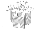
- FIG. 2 is a perspective view of a main part of the stator core of the rotating electric machine according to the first embodiment.
- the teeth 6 include a plurality of tooth pieces 11.
- Each of the plurality of tooth pieces 11 includes a connection piece 12.
- the connecting piece 12 includes a pair of fixing holes 7a.
- the teeth 6 are stacked such that the connecting pieces 12 of the adjacent tooth pieces 11 are alternately arranged.
- the first set of fixing holes 7 a is arranged on one side of the joint portion 7.
- the second set of fixing holes 7 a is arranged on the other side of the joint 7.
- the adjacent teeth 6 are arranged so that the connecting pieces 12 are engaged with each other.
- the first set of fixing holes 7a and the second set of fixing holes 7a are connected to each other.
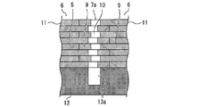
- FIGS. 3 and 4 are longitudinal sectional views of main parts of the stator core of the rotating electric machine according to the first embodiment.
- the housing 13 is adjacent to the teeth 6.
- the housing 13 has a support hole 13a.
- the supporting holes 13a are connected to the first set of fixing holes 7a and the second set of fixing holes 7a of the adjacent teeth 6 with each other.
- the first set of fixing holes 7 a and the second set of fixing holes 7 a are formed to be shifted from each other in the width direction of the tooth piece 11.
- the filling body 10 is a resin.
- the filling body 10 is filled together with the first set of fixing holes 7a, the second set of fixing holes 7a, and the support holes 13a.
- the fillers 10 are collectively filled in the fixing holes 7 a. Therefore, the rigidity of the stator core 3 can be easily increased at low cost without requiring shrink fitting, welding, caulking, or the like. Further, the size of the rotating electric machine can be reduced.
- the fixing holes 7a are connected in a shifted state. For this reason, by using together with the joint wrap structure, not only the rigidity of the adjacent teeth 6 in the rotating direction but also the rigidity of the teeth pieces 11 in the laminating direction can be easily increased.
- the filler 10 is filled in the first set of fixing holes 7a, the second set of fixing holes 7a, and the support holes 13a. For this reason, it is possible to fix the stator core 3 to the housing 13 in a state where the stator core 3 is maintained in an annular shape only by the filler 10. As a result, shrink fitting becomes unnecessary, and the strength of the housing 13 is not required. Therefore, the rigidity of stator core 3 can be more easily increased.
- the amount of the filler 10 can be reduced, and large equipment is not required, as compared with a molding method in which most of the stator core 3 is covered with resin. Therefore, the rotating electric machine can be manufactured at low cost.
- the adjacent teeth 6 are fixed at a plurality of locations. Therefore, the force can be received by a small amount of the filling body 10.
- adjacent teeth 6 may be fixed at three or more places, or may be fixed at one place. Also in this case, the rigidity of the stator core 3 can be increased at low cost.
- the shape of the fixing hole 7a may be a polygon, an ellipse, or the like. Also in this case, the rigidity of the stator core 3 can be increased at low cost.
- a notch may be provided in the fixing hole 7a. In this case, a function of preventing the tooth pieces 11 from coming off in the stacking direction can be added.
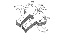
- FIG. 5 and 6 are perspective views of a main part of the stator core of the rotating electric machine according to the second embodiment.
- the same or corresponding parts as those in the first embodiment are denoted by the same reference numerals. The description of this part is omitted.
- each of the first and second sets of fixing holes 7a is one.
- the tooth 6 has a fixing groove 14.
- the fixing groove 14 is formed on the connecting portion of the joint portion 7 on the side opposite to the teeth portion 8.
- the fixing groove 14 is formed on the boundary between the adjacent teeth 6.
- the fixing groove 14 has a concave portion 14a.
- the recess 14 a is formed obliquely from the fixing groove 14 toward the center of the joint 7.
- the filling body 10 is filled in both the fixing hole 7a and the fixing groove 14.
- the filling body 10 is filled in both the fixing holes 7a and the fixing grooves 14. At this time, the filling body 10 is also filled into the recess 14a. Therefore, the force applied to the stator core 3 can be received not only by the tension of the filler 10 but also by the compression and shearing of the filler 10. As a result, high rigidity can be obtained even with a small amount of the filler 10.
- a support groove may be formed in the housing 13.
- the stator core 3 can be fixed to the housing 13 while maintaining the stator core 3 in an annular shape.
- the teeth 6 adjacent to at least one of the fixing hole 7a and the fixing groove 14 may be fixed. Also in this case, the rigidity of the stator core 3 can be increased at low cost.
- the rotating electric machines according to the first and second embodiments may be used for a hoist of an elevator.
- the hoist can be made smaller.
- a stator core 3 in which a plurality of divided joint wrap cores are connected may be used. Also in this case, the rigidity of the stator core 3 can be easily increased at low cost by applying the filler 10 to the joint wrap core.
- stator core and the rotating electric machine of the rotating electric machine according to the present invention can be used for an elevator system.
Landscapes
- Engineering & Computer Science (AREA)
- Power Engineering (AREA)
- Iron Core Of Rotating Electric Machines (AREA)
Abstract
剛性を容易に高めることができる回転電機のステータコアを提供する。回転電機のステータコアは、ジョイント部とティース部とを備え、前記ジョイント部の両側に固定用穴および固定用溝の少なくとも一方が形成された複数のティースと、隣接したティースのジョイント部が互いの固定用穴および固定用溝の少なくとも一方がつながった状態で連結されることで前記複数のティースが環状に配置された際に、隣接したティースのジョイント部に対して互いの固定用穴または固定用溝にまとめて充填された充填体と、を備えた。
Description
この発明は、回転電機のステータコアおよび回転電機に関する。
特許文献1は、回転電機のステータコアを開示する。ステータコアは、複数のティースを備える。複数のティースは、環状に固定される。
しかしながら、特許文献1に記載のステータコアにおいては、焼嵌め等により剛性を高める必要がある。このため、ステータコアの生産性が悪い。
この発明は、上述の課題を解決するためになされた。この発明の目的は、剛性を容易に高めることができる回転電機のステータコアおよび回転電機を提供することである。
この発明に係る回転電機のステータコアは、ジョイント部とティース部とを備え、前記ジョイント部の両側に固定用穴および固定用溝の少なくとも一方が形成された複数のティースと、隣接したティースのジョイント部が互いの固定用穴および固定用溝の少なくとも一方がつながった状態で連結されることで前記複数のティースが環状に配置された際に、隣接したティースのジョイント部に対して互いの固定用穴または固定用溝にまとめて充填された充填体と、を備えた。
この発明に係る回転電機は、前記ステータコアにおいて隣接したティースのジョイント部が互いの固定用穴および固定用溝の少なくとも一方がつながった状態で連結されることで前記複数のティースが環状に配置された際に、隣接したティースのジョイント部の互いの固定用穴および固定用溝の少なくとも一方に繋がった支持用穴および支持用溝の少なくとも一方が形成され、前記支持用穴および前記支持用溝の少なくとも一方に前記充填体が充填されたハウジング、を備えた。
この発明によれば、隣接したティースにおいて、充填体は、互いの固定用穴または固定用溝にまとめて充填される。このため、ステータコアの剛性を容易に高めることができる。
この発明を実施するための形態について添付の図面に従って説明する。なお、各図中、同一または相当する部分には同一の符号が付される。当該部分の重複説明は適宜に簡略化ないし省略する。
実施の形態1.
図1は実施の形態1における回転電機のステータコアが適用される回転電機の構成図である。
図1は実施の形態1における回転電機のステータコアが適用される回転電機の構成図である。
図1に示されるように、回転電機は、ロータ1とステータ2とを備える。
ロータ1は、円柱状に設けられる。ステータ2は、ステータコア3と複数の絶縁部材4と複数の巻線5とを備える。
ステータコア3は、ジョイントラップコアである。ステータコア3は、複数のティース6を備える。複数のティース6の各々は、ジョイント部7とティース部8とを備える。
ジョイント部7は、複数の固定用穴7aを備える。例えば、複数の固定用穴7aは、円形に形成される。第1組の固定用穴7aは、ジョイント部7の一側に形成される。第2組の固定用穴7aは、ジョイント部7の他側に形成される。隣接したジョイント部7は、回転軸9を介して互いに回転可能に連結される。ティース部8は、ジョイント部7に連結される。ティース部8は、ジョイント部7から突き出す。
複数の絶縁部材4の各々は、複数のティース部8の各々の外周面を覆う。
複数の巻線5の各々は、複数の絶縁部材4の各々の外周面に巻き付けられる。
複数のティース6が全体として環状に配置された際、隣接したティース6のジョイント部7において、互いの第1組の固定用穴7aと第2組の固定用穴7aとが複数のティース6で形成された円形状の軸方向につながる。この状態において、充填体10は、隣接したティース6のジョイント部7に対して互いの固定用穴7aにまとめて充填される。その結果、複数のティース6の回転が抑制される。
次に、図2を用いて、ティース6を説明する。
図2は実施の形態1における回転電機のステータコアの要部の斜視図である。
図2は実施の形態1における回転電機のステータコアの要部の斜視図である。
図2に示されるように、ティース6は、複数のティース片11を備える。複数のティース片11の各々は、連結片12を備える。連結片12は、一対の固定用穴7aを備える。
ティース6は、隣接したティース片11の連結片12が互い違いに配置されるように積層される。その結果、第1組の固定用穴7aは、ジョイント部7の一側に配置される。第2組の固定用穴7aは、ジョイント部7の他側に配置される。
隣接したティース6は、互いの連結片12を噛み合わせるように配置される。その結果、隣接したティース6のジョイント部7において、互いの第1組の固定用穴7aと第2組の固定用穴7aとがつながる。
次に、図3と図4とを用いて、隣接したティース6の連結部を説明する。
図3と図4とは実施の形態1における回転電機のステータコアの要部の縦断面図である。
図3と図4とは実施の形態1における回転電機のステータコアの要部の縦断面図である。
図3と図4とに示されるように、ハウジング13は、ティース6に隣接する。ハウジング13は、支持用穴13aを備える。支持用穴13aは、隣接したティース6における互いの第1組の固定用穴7aと第2組の固定用穴7aとつながる。
隣接したティース6において、互いの第1組の固定用穴7aと第2組の固定用穴7aとは、ティース片11の幅方向にずれて形成される。
例えば、充填体10は、樹脂である。充填体10は、互いの第1組の固定用穴7aと第2組の固定用穴7aと支持用穴13aとにまとめて充填される。
以上で説明した実施の形態1によれば、隣接したティース6において、充填体10は、互いの固定用穴7aにまとめて充填される。このため、焼嵌め、溶接、かしめ等を要することなく、ステータコア3の剛性を安価かつ容易に高めることができる。また、回転電機を小さくすることができる。
また、隣接したティース6において、互いの固定用穴7aは、ずれた状態でつながる。このため、ジョイントラップ構造と併用することで、隣接したティース6に対し、回転方向の剛性を高めるだけでなく、ティース片11の積層方向の剛性を簡単に高めることができる。
また、充填体10は、互いの第1組の固定用穴7aと第2組の固定用穴7aと支持用穴13aとにまとめて充填される。このため、ステータコア3を環状に維持した状態でハウジング13に固定することを充填体10のみで行うことができる。その結果、焼嵌めが不要となり、ハウジング13の強度を要することもなくなる。このため、ステータコア3の剛性をより容易に高めることができる。
また、ステータコア3のほとんどを樹脂で覆うモールド方式等に比べ、充填体10の量を少なくすることができ、大きな設備も不要となる。このため、回転電機を安価に製造することができる。
また、隣接したティース6は、複数の箇所で固定される。このため、少ない量の充填体10で力を受けることができる。
なお、隣接したティース6は、3か所以上の箇所で固定されてもよいし、1箇所で固定されてもよい。この場合も、ステータコア3の剛性を安価に高めることができる。
また、固定用穴7aの形状を多角形、楕円形等としてもよい。この場合も、ステータコア3の剛性を安価に高めることができる。
また、固定用穴7aに切り欠きを設けてもよい。この場合、ティース片11の積層方向への抜け止めの機能を追加することができる。
実施の形態2.
図5と図6とは実施の形態2における回転電機のステータコアの要部の斜視図である。なお、実施の形態1の部分と同一又は相当部分には同一符号が付される。当該部分の説明は省略される。
図5と図6とは実施の形態2における回転電機のステータコアの要部の斜視図である。なお、実施の形態1の部分と同一又は相当部分には同一符号が付される。当該部分の説明は省略される。
実施の形態2のティース6において、第1組および第2組の固定用穴7aは、それぞれ1つである。
ティース6は、固定用溝14を備える。固定用溝14は、ジョイント部7の連結部においてティース部8とは反対側に形成される。固定用溝14は、隣接したティース6の境界上に形成される。固定用溝14は、凹部14aを備える。凹部14aは、固定用溝14からジョイント部7の中央部に向けて斜めに形成される。
充填体10は、固定用穴7aと固定用溝14との双方に充填される。
以上で説明した実施の形態2によれば、充填体10は、固定用穴7aと固定用溝14との双方に充填される。この際、充填体10は、凹部14aへも充填される。このため、充填体10の引張だけでなく、充填体10の圧縮およびせん断でもステータコア3にかかる力を受けることができる。その結果、少ない量の充填体10でも高い剛性を得ることができる。
なお、ハウジング13に支持用溝を形成してもよい。この場合、充填体10が固定用溝14と支持用溝にまとめて充填されれば、ステータコア3を環状に維持した状態でハウジング13に固定することができる。
また、固定用穴7aおよび固定用溝14の少なくとも一方で隣接したティース6を固定してもよい。この場合も、ステータコア3の剛性を安価に高めることができる。
また、実施の形態1および実施の形態2の回転電機をエレベーターの巻上機に用いてもよい。この場合、巻上機を小さくすることができる。
また、実施の形態1および実施の形態2において、分割された複数のジョイントラップコアを連結したステータコア3を用いてもよい。この場合も、ジョイントラップコアに対し、充填体10を適用することで、ステータコア3の剛性を安価かつ容易に高めることができる。
以上のように、この発明に係る回転電機のステータコアおよび回転電機は、エレベーターシステムに利用できる。
1 ロータ、 2 ステータ、 3 ステータコア、 4 絶縁部材、 5 巻線、 6 ティース、 7 ジョイント部、 7a 固定用穴、 8 ティース部、 9 回転軸、 10 充填体、 11 ティース片、 12 連結片、 13 ハウジング、 13a 支持用穴、 14 固定用溝、 14a 凹部
Claims (6)
- ジョイント部とティース部とを備え、前記ジョイント部の両側に固定用穴および固定用溝の少なくとも一方が形成された複数のティースと、
隣接したティースのジョイント部が互いの固定用穴および固定用溝の少なくとも一方がつながった状態で連結されることで前記複数のティースが環状に配置された際に、隣接したティースのジョイント部に対して互いの固定用穴または固定用溝にまとめて充填された充填体と、
を備えた回転電機のステータコア。 - 前記隣接したティースは、前記複数のティースが環状に配置された際に、互いの固定用穴および固定用溝の少なくとも一方がずれた状態でつながるように形成された請求項1に記載の回転電機のステータコア。
- 前記複数のティースは、前記ジョイント部の両側に固定用穴および固定用溝の少なくとも一方が2つ以上形成された請求項1または請求項2に記載の回転電機のステータコア。
- 前記複数のティースは、前記ジョイント部の両側に固定用穴および固定用溝が形成された請求項1または請求項2に記載の回転電機のステータコア。
- 請求項1から請求項4のいずれか一項に記載のステータコアにおいて隣接したティースのジョイント部が互いの固定用穴および固定用溝の少なくとも一方がつながった状態で連結されることで前記複数のティースが環状に配置された際に、隣接したティースのジョイント部の互いの固定用穴および固定用溝の少なくとも一方につながった支持用穴および支持用溝の少なくとも一方が形成され、前記支持用穴および前記支持用溝の少なくとも一方に前記充填体が充填されたハウジング、
を備えた回転電機。 - 前記ステータコアと前記ハウジングとは、エレベーターの巻上機に用いられた請求項5に記載の回転電機。
Priority Applications (1)
| Application Number | Priority Date | Filing Date | Title |
|---|---|---|---|
| PCT/JP2018/032409 WO2020044551A1 (ja) | 2018-08-31 | 2018-08-31 | 回転電機のステータコアおよび回転電機 |
Applications Claiming Priority (1)
| Application Number | Priority Date | Filing Date | Title |
|---|---|---|---|
| PCT/JP2018/032409 WO2020044551A1 (ja) | 2018-08-31 | 2018-08-31 | 回転電機のステータコアおよび回転電機 |
Publications (1)
| Publication Number | Publication Date |
|---|---|
| WO2020044551A1 true WO2020044551A1 (ja) | 2020-03-05 |
Family
ID=69644036
Family Applications (1)
| Application Number | Title | Priority Date | Filing Date |
|---|---|---|---|
| PCT/JP2018/032409 Ceased WO2020044551A1 (ja) | 2018-08-31 | 2018-08-31 | 回転電機のステータコアおよび回転電機 |
Country Status (1)
| Country | Link |
|---|---|
| WO (1) | WO2020044551A1 (ja) |
Citations (10)
| Publication number | Priority date | Publication date | Assignee | Title |
|---|---|---|---|---|
| JPS54147406A (en) * | 1978-05-10 | 1979-11-17 | Matsushita Electric Works Ltd | Stator for mini-motor |
| JPH11332136A (ja) * | 1998-05-15 | 1999-11-30 | Fanuc Ltd | 電動機のステータ構造 |
| JP2002359940A (ja) * | 2001-06-01 | 2002-12-13 | Mitsubishi Electric Corp | ステータコアおよびこのステータコアを適用した回転電動機 |
| JP2006223076A (ja) * | 2005-02-14 | 2006-08-24 | Toshiba Corp | アウターロータ及びその製造方法 |
| JP2010213496A (ja) * | 2009-03-11 | 2010-09-24 | Honda Motor Co Ltd | ステータおよびモータ |
| JP2011114876A (ja) * | 2009-11-24 | 2011-06-09 | Mitsubishi Electric Corp | 回転電機のステータコア |
| JP2013247710A (ja) * | 2012-05-23 | 2013-12-09 | Honda Motor Co Ltd | モータのステータ |
| JP2015144546A (ja) * | 2013-11-08 | 2015-08-06 | 三星電子株式会社Samsung Electronics Co.,Ltd. | モータ及びその製造方法 |
| JP2016086508A (ja) * | 2014-10-24 | 2016-05-19 | 株式会社三井ハイテック | 電機子鉄心及び電機子鉄心の製造方法 |
| US20170353089A1 (en) * | 2016-06-01 | 2017-12-07 | Ge Energy Power Conversion Technology Ltd | Stators for electrical machines |
-
2018
- 2018-08-31 WO PCT/JP2018/032409 patent/WO2020044551A1/ja not_active Ceased
Patent Citations (10)
| Publication number | Priority date | Publication date | Assignee | Title |
|---|---|---|---|---|
| JPS54147406A (en) * | 1978-05-10 | 1979-11-17 | Matsushita Electric Works Ltd | Stator for mini-motor |
| JPH11332136A (ja) * | 1998-05-15 | 1999-11-30 | Fanuc Ltd | 電動機のステータ構造 |
| JP2002359940A (ja) * | 2001-06-01 | 2002-12-13 | Mitsubishi Electric Corp | ステータコアおよびこのステータコアを適用した回転電動機 |
| JP2006223076A (ja) * | 2005-02-14 | 2006-08-24 | Toshiba Corp | アウターロータ及びその製造方法 |
| JP2010213496A (ja) * | 2009-03-11 | 2010-09-24 | Honda Motor Co Ltd | ステータおよびモータ |
| JP2011114876A (ja) * | 2009-11-24 | 2011-06-09 | Mitsubishi Electric Corp | 回転電機のステータコア |
| JP2013247710A (ja) * | 2012-05-23 | 2013-12-09 | Honda Motor Co Ltd | モータのステータ |
| JP2015144546A (ja) * | 2013-11-08 | 2015-08-06 | 三星電子株式会社Samsung Electronics Co.,Ltd. | モータ及びその製造方法 |
| JP2016086508A (ja) * | 2014-10-24 | 2016-05-19 | 株式会社三井ハイテック | 電機子鉄心及び電機子鉄心の製造方法 |
| US20170353089A1 (en) * | 2016-06-01 | 2017-12-07 | Ge Energy Power Conversion Technology Ltd | Stators for electrical machines |
Similar Documents
| Publication | Publication Date | Title |
|---|---|---|
| US11075559B2 (en) | Stator of rotating electric machine | |
| WO2013145976A1 (ja) | 回転電機のステータ構造 | |
| JP2009142031A (ja) | 回転電機用ステータ | |
| WO2019073724A1 (ja) | 回転電機の固定子 | |
| JP2020078118A (ja) | モータ、および電動バイク | |
| US10396613B2 (en) | Armature, rotating electrical device, and armature manufacturing method | |
| WO2013118777A1 (ja) | 磁石式発電機 | |
| JPWO2018043364A1 (ja) | 巻線固定構造体、及び電動機 | |
| US10312778B2 (en) | Stator of rotary electric machine and method for manufacturing same | |
| US9461514B2 (en) | Bobbin and rotary electric machine | |
| JP5495045B2 (ja) | 回転電機の回転子 | |
| WO2019064376A1 (ja) | 回転電機 | |
| JP2021158875A (ja) | 回転電機 | |
| JP5954693B2 (ja) | インシュレータ及び回転電機 | |
| WO2020044551A1 (ja) | 回転電機のステータコアおよび回転電機 | |
| JPWO2019235071A1 (ja) | 回転電機の固定子および回転電機 | |
| JP2015109783A (ja) | 回転電機 | |
| JP5020660B2 (ja) | アーマチャ及びモータ | |
| JP5155782B2 (ja) | アーマチャ及びモータ | |
| JPWO2021240851A5 (ja) | ||
| JP5466117B2 (ja) | 電動機のステータの製造方法および固定子用コイルの位置決め方法 | |
| JP6758359B2 (ja) | 回転電機 | |
| JP5968125B2 (ja) | 電動機の固定子 | |
| JP2019118166A (ja) | 回転電機のステータ | |
| KR100669046B1 (ko) | 모터의 스테이터 |
Legal Events
| Date | Code | Title | Description |
|---|---|---|---|
| 121 | Ep: the epo has been informed by wipo that ep was designated in this application |
Ref document number: 18932248 Country of ref document: EP Kind code of ref document: A1 |
|
| NENP | Non-entry into the national phase |
Ref country code: DE |
|
| 122 | Ep: pct application non-entry in european phase |
Ref document number: 18932248 Country of ref document: EP Kind code of ref document: A1 |
|
| NENP | Non-entry into the national phase |
Ref country code: JP |