WO2020044449A1 - 部品供給装置及びこれを備えた部品実装機 - Google Patents
部品供給装置及びこれを備えた部品実装機 Download PDFInfo
- Publication number
- WO2020044449A1 WO2020044449A1 PCT/JP2018/031862 JP2018031862W WO2020044449A1 WO 2020044449 A1 WO2020044449 A1 WO 2020044449A1 JP 2018031862 W JP2018031862 W JP 2018031862W WO 2020044449 A1 WO2020044449 A1 WO 2020044449A1
- Authority
- WO
- WIPO (PCT)
- Prior art keywords
- tape
- component
- sending
- unit
- component storage
- Prior art date
- Legal status (The legal status is an assumption and is not a legal conclusion. Google has not performed a legal analysis and makes no representation as to the accuracy of the status listed.)
- Ceased
Links
Images














Classifications
-
- H—ELECTRICITY
- H05—ELECTRIC TECHNIQUES NOT OTHERWISE PROVIDED FOR
- H05K—PRINTED CIRCUITS; CASINGS OR CONSTRUCTIONAL DETAILS OF ELECTRIC APPARATUS; MANUFACTURE OF ASSEMBLAGES OF ELECTRICAL COMPONENTS
- H05K13/00—Apparatus or processes specially adapted for manufacturing or adjusting assemblages of electric components
- H05K13/04—Mounting of components, e.g. of leadless components
- H05K13/0417—Feeding with belts or tapes
- H05K13/0419—Feeding with belts or tapes tape feeders
Definitions
- the present invention relates to a component supply device that supplies components stored in a component storage tape, and a component mounting machine including the component supply device.
- a component mounter for mounting (mounting) an electronic component (hereinafter, simply referred to as a “component”) on a substrate such as a printed wiring board includes a component supply device that supplies the component to a component pickup position.
- a component supply device a tape feeder using a component storage tape in which components are stored is known.
- the tape feeder is a splicing device that continuously supplies components while connecting a subsequent tape for replenishment to a rear end of the preceding tape when parts remaining in the preceding tape, in which component supply is performed in advance, are running short. It was a method.
- a tape feeder of a splicing-less type also referred to as an automatic loading type
- This automatic loading type tape feeder is disclosed in Patent Documents 1 and 2, for example.
- an automatic loading type tape feeder if the leading end of the tape is set at a predetermined position, the tape can be automatically loaded to a component take-out position in response to a button operation. Also, if the leading end of the replenishing subsequent tape is set at the predetermined position, the replenishing subsequent tape is automatically loaded to the component take-out position after the part of the preceding tape has run out, and the replenishing subsequent tape is set. , An intermittent tape sending operation is started.
- the automatic loading type tape feeder the operator is released from complicated tape joining work, and the so-called tape feeder setup work and component supply work are made more efficient.
- the present invention has been made in view of such circumstances, and a purpose thereof is to efficiently supply components in a component supply device that supplies components stored in a component storage tape to a component pickup position. It is an object of the present invention to provide a component supply device capable of performing the above-described operations and a component mounter including the same.
- a component supply device is an apparatus that supplies a component to a component removal position by using a component storage tape in which a plurality of component storage units capable of storing components are arranged at predetermined intervals. is there.
- the component supply device includes a tape running path that is a path leading to the component take-out position of the component storage tape, and introducing the component storage tape into the tape running path, and moving the component in a tape sending direction toward the component take-out position.
- a tape introduction / delivery mechanism for delivering a storage tape, and the component storage tape, which is arranged on the tape traveling path and is introduced into the tape traveling path by the tape introduction / delivery mechanism, is received, and each of the component storage sections sequentially receives the component.
- a tape receiving and sending mechanism for sending out the component storage tape along the tape running path so as to pass through the take-out position, and a control unit for controlling the tape introducing and sending mechanism and the tape receiving and sending mechanism are provided.
- the control unit may be configured such that the trailing edge of the preceding tape, which is a component storage tape that precedes the supply of components at the component removal position while being sent out by the tape receiving / sending mechanism, is more tape than the tape receiving / sending mechanism.
- the tape introduction / delivery mechanism introduces a subsequent tape, which is a component storage tape following the preceding tape, into the tape traveling path by the tape introduction / delivery mechanism.
- a first introduction operation to be sent toward the preceding tape is started, and when it is determined that the last component stored in the component storage unit of the preceding tape has been taken out and the preceding tape has run out of components, When the trailing edge of the tape has passed the second position between the first position and the component removal position, Simultaneously with execution of the first introduction operation for the by tape receiving delivery mechanism, wherein by sending the preceding tape to the tape-feeding direction downstream side to perform the discharge operation for discharging than the component pickup position.
- the component supply device described above and the preceding tape that supplies components in advance by sending out the tape receiving and sending mechanism in the component supply device has run out of components.
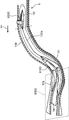
- FIG. 4 is a perspective view illustrating a configuration of a tape running path forming unit provided in the component supply device.
- FIG. 4 is a perspective view of a tape introduction / delivery mechanism provided in the component supply device.
- FIG. 7 is a perspective view of the tape introduction / delivery mechanism with one frame removed, showing a state where the tape holding unit is in a holding posture.
- FIG. 5 is a perspective view of the tape introduction / delivery mechanism with one frame removed, showing the tape holding unit in a holding release position; It is a perspective view which expands and shows the vicinity of a connection part in a tape introduction / delivery mechanism.
- FIG. 4 is a diagram illustrating a tape feeding mechanism provided in the component supply device when viewed from a tape feeding direction.
- FIG. 3 is a perspective view illustrating a configuration of a component exposure unit provided in the component supply device.
- FIG. 3 is a block diagram illustrating an electrical configuration of the component supply device.
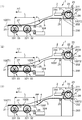
- FIG. 9 is a diagram illustrating a first example of tape sending control in the component supply device.
- FIG. 9 is a diagram illustrating a first example of tape sending control in the component supply device.
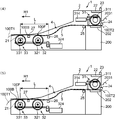
- FIG. 8 is a diagram illustrating a second example of the tape delivery control in the component supply device.
- FIG. 8 is a diagram illustrating a second example of the tape delivery control in the component supply device.
- FIG. 13 is a diagram illustrating a third example of the tape delivery control in the component supply device.
- FIG. 13 is a diagram illustrating a third example of the tape delivery control in the component supply device. It is a figure explaining operation of the information part provided in the parts supply device.
- the X axis direction is a direction parallel to the horizontal plane
- the Y axis direction is a direction orthogonal to the X axis direction on the horizontal plane
- the Z axis direction is a vertical direction orthogonal to both the X and Y directions.
- one side in the X-axis direction is referred to as “+ X side”
- the other side opposite to the one direction side in the X-axis direction is referred to as “ ⁇ X side”.
- the one direction side in the Y-axis direction is referred to as “+ Y side”, and the other direction side opposite to the one direction side in the Y-axis direction is referred to as “ ⁇ Y side”.
- the upper side, which is one side in the Z-axis direction, is referred to as “+ Z side”, and the lower side, which is the other side opposite to the one direction side in the Z-axis direction, is referred to as “ ⁇ Z side”.
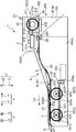
- FIG. 1 is a plan view of a component mounter 10 according to an embodiment of the present invention as viewed from above.
- FIG. 2 is a side view of the cylindrical body 17, the tape cutting device 18, and the component supply device 1 provided in the component mounting machine 10.
- the component mounter 10 is a device that mounts (mounts) components on the board E1 and produces an electronic circuit board (component mounting board).
- the component mounter 10 includes a component supply unit 10A in which a plurality of component supply devices 1 are arranged in the X-axis direction, a main body frame 11, a moving frame 12, a conveyor 13, a head unit 14, a first drive mechanism. 15, a second drive mechanism 16, a cylindrical body 17, and a tape cutting device 18.
- the main body frame 11 is a structure in which the components of the component mounter 10 are arranged, and is formed in a substantially rectangular shape in plan view when viewed from the Z-axis direction.
- the conveyor 13 extends in the X-axis direction and is disposed on the main body frame 11.
- the conveyor 13 conveys the board E1 in the X-axis direction.
- the board E1 is transported on the conveyor 13 and is positioned at a predetermined work position (a component mounting position where components are mounted on the board E1).
- the moving frame 12 extends in the X-axis direction, and is supported by the main body frame 11 so as to be movable in a predetermined moving direction (Y-axis direction).
- a head unit 14 is mounted on the moving frame 12.
- the head unit 14 is mounted on the moving frame 12 so as to be movable in the X-axis direction. That is, the head unit 14 can move in the Y-axis direction along with the movement of the moving frame 12, and can move in the X-axis direction along the moving frame 12.
- the head unit 14 is movable over a predetermined work position of the substrate E1 conveyed by the component supply device 1 and the conveyor 13, takes out the component supplied to the component removal position by the component supply device 1, and takes out the component.
- the component is mounted (mounted) on the substrate E1.
- the head unit 14 includes a suction nozzle, which is a holder capable of holding a component mounted on the substrate E1 by suction.
- the suction nozzle can communicate with any one of a negative pressure generator, a positive pressure generator, and the atmosphere via an electric switching valve.
- the supply of the negative pressure to the suction nozzle enables the suction and holding of the component by the suction nozzle (removal of the component), and then the supply of the positive pressure cancels the suction and holding of the component.
- the holding tool other than the suction nozzle may be, for example, a chuck that holds and holds a component.
- the first drive mechanism 15 is disposed at the + X side and the ⁇ X side end of the main body frame 11.
- the first drive mechanism 15 is a mechanism that moves the moving frame 12 in the Y-axis direction.
- the first drive mechanism 15 includes, for example, a drive motor, a ball screw shaft extending in the Y-axis direction and connected to the drive motor, and a ball nut disposed on the moving frame 12 and screwed to the ball screw shaft. It is comprised including.
- the first driving mechanism 15 having such a configuration moves the moving frame 12 in the Y-axis direction by advancing and retreating the ball nut along the ball screw axis with the rotation driving of the ball screw shaft by the driving motor.
- the second drive mechanism 16 is provided on the moving frame 12.
- the second drive mechanism 16 is a mechanism that moves the head unit 14 in the X-axis direction along the moving frame 12.
- the second drive mechanism 16 includes, for example, a drive motor, a ball screw shaft extending in the X-axis direction and connected to the drive motor, and a ball screw shaft And a ball nut to be screwed together.
- the second drive mechanism 16 having such a configuration moves the head unit 14 in the X-axis direction by advancing and retracting the ball nut along the ball screw axis with the rotation of the ball screw shaft by the drive motor.
- the cylindrical body 17 is formed in a cylindrical shape having an upper opening 17A and a lower opening 17B, as shown in FIG.
- the cylindrical body 17 receives the component storage tape discharged from the component supply device 1 from the upper opening 17A and guides the discharge of the component storage tape.
- the cylindrical body 17 includes a first wall 171 and a second wall 172 which are walls defining an upper opening 17A and a lower opening 17B.
- the first wall portion 171 is a wall portion having a length facing all the component supply devices 1 arranged side by side in the X-axis direction.
- the second wall portion 172 is a wall portion that is disposed to face the first wall portion 171 on the upstream side ( ⁇ Y side) in the tape sending direction.
- the cylindrical body 17 has an upper opening formed by a first wall portion 171 and a second wall portion 172 and a pair of side wall portions connecting ends of the first wall portion 171 and the second wall portion 172 in the X-axis direction. It is formed in a box-like cylindrical shape having a lower opening 17B and a lower opening 17A.
- the tape cutting device 18 is disposed facing the lower opening 17B of the cylindrical body 17, and cuts the component storage tape discharged from the cylindrical body 17 through the lower opening 17B at a predetermined timing.
- the component storage tape discharged from the lower opening 17 ⁇ / b> B of the cylindrical body 17 is cut into strips by the tape cutting device 18.
- the cut pieces cut by the tape cutting device 18 fall in a predetermined collection path and are collected in a collection box.
- the tape cutting device 18 may be provided for each of the plurality of component supply devices 1, but one tape cutting device 18 is provided for each of the plurality of component supply devices 1, such as for each of the component supply units 10 ⁇ / b> A, and is discharged from the plurality of supply devices 1. May be cut at once.
- FIG. 3 is a side view of the component supply device 1 provided in the component mounter 10.
- the component supply device 1 is an automatic loading type tape feeder that supplies a component to a component pick-up position 21 by sending out a component storage tape 100 in which components are stored in a tape sending direction H1.
- the component supplied to the component removal position 21 by the component supply device 1 is removed from the component storage tape 100 by the head unit 14 provided in the component mounter 10, and then mounted on the board E1.
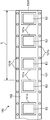
- FIG. 4 is a diagram illustrating a configuration of the component storage tape 100 used in the component supply device 1.
- FIG. 4A is a cross-sectional view of the state where the component storage tape 100 is cut along the tape sending direction H1.
- FIG. 4B is a perspective view of the component storage tape 100.
- the component storage tape 100 includes a carrier tape 101 and a cover tape 102, and is mounted on the component supply device 1.
- the carrier tape 101 is a tape in which a plurality of component storage units 101a storing components E2 are arranged at predetermined intervals. Further, the carrier tape 101 has predetermined holes 101b at both ends in the width direction to be fitted with the teeth of the first sprocket 311, the second sprocket 321 and the third sprocket 331 of the tape feeding mechanism 3 described later. They are arranged at intervals.
- the phrase "the hole 101b of the component storage tape 100 fits the teeth of the first sprocket 311, the second sprocket 321 and the third sprocket 331" means that the teeth fit into the holes 101b and the first sprocket 311, the state in which the component storage tape 100 can be sent out in conjunction with the rotation of the second sprocket 321 and the third sprocket 331.
- the cover tape 102 is a tape attached to the carrier tape 101 so as to cover the component storage unit 101a.
- the cover tape 102 is attached to the carrier tape 101 by joining both ends in the width direction to the carrier tape 101.
- joining portions 103 formed by joining the cover tape 102 are formed linearly at both ends in the width direction on the upper surface of the carrier tape 101 along the edges in the width direction of the cover tape 102. Have been.
- the joining portion 103 is provided on the inner side than the hole portion 101b.
- the length K1 between the joining portions 103 formed at both ends in the width direction of the carrier tape 101 is substantially equal to the length in the width direction of the cover tape 102.
- the length K2 (tape width) of the component storage tape 100 in the width direction is the same as the length of the carrier tape 101 in the width direction.
- the component storage tape 100 is, for example, a wide tape having a tape width K2 of 32 mm or more.
- the component storage tape 100 is elongated in the direction in which the component storage portions 101a are arranged and stores a large number of components E2.
- the component storage tape 100 is wound around an axis extending in the width direction of the component storage tape 100 and has a circular reel shape.
- the part E2 can be supplied in the packaging form of (1).
- the reel is mounted on a table (not shown) in front of the component supply device 1 (on the right side in FIG. 3), and the component storage tape 100 fed out therefrom is mounted on the component supply device 1.
- component storage tape 100 is illustrated in FIG. 5C and the first component storage tape illustrated in FIGS. 5A and 5B according to the storage state of the component E2 in the component storage unit 101a at the rear end. It is roughly divided into the second component storage tape.
- the component storage tape 100 illustrated in FIG. 5A is a tape in which an empty component storage portion 101a in which the component E2 is not stored is not arranged at the rear end. That is, in the component storage tape 100 illustrated in FIG. 5A, the component E2 is stored in all of the component storage portions 101a arranged at the rear end.
- the component storage tape 100 illustrated in FIG. 5B is a tape in which an empty component storage portion 101a in which the component E2 is not stored within a range of a predetermined reference length L from the rear edge 100B is arranged.
- the area where the empty component storage 101a is arranged is a portion generally called a "trailer", and the length of the "trailer” is standardized.
- the length of the “trailer section” is 160 mm or more.
- the reference length L is set to “160 mm”.
- the component supply device 1 includes an apparatus main body 2, a tape feeding mechanism 3, a tape traveling path forming unit 4, a component exposing unit 6, a tape traveling guide unit 7, and a tape discharging guide unit 8. And a tape introduction / delivery mechanism 200.
- the apparatus main body 2 is a housing that accommodates each part of the component supply device 1.
- the device main body 2 is provided with an operation unit 22 and a notification unit 23.
- the operation unit 22 is a portion where an instruction for operating the component supply device 1 is input by an operator.
- the notification unit 23 is a part that forms part of the tape introduction / transmission mechanism 200 and notifies the operator of various types of information.
- the tape delivery mechanism 3 is a mechanism for delivering the component storage tape 100 in a predetermined tape delivery direction H1 along the arrangement direction of the component storage units 101a, with the cover tape 102 facing upward and toward the component removal position 21.
- the tape delivery direction H1 when the tape delivery mechanism 3 delivers the component storage tape 100 toward the component removal position 21 is a direction from the ⁇ Y side to the + Y side.
- the tape feeding mechanism 3 performs a loading operation of feeding the component storage tape 100 in the tape feeding direction H1 toward the component pick-up position 21 and a direction from the + Y side to the ⁇ Y side in a direction opposite to the tape sending direction H1. And an unloading operation for sending the component storage tape 100 to the device.
- the tape running path forming section 4 forms the tape running path 5 of the component storage tape 100 delivered by the tape delivery mechanism 3 to the component take-out position 21. As shown in FIGS. 3 and 6, the tape running path forming section 4 includes a pair of guide walls 41.
- the pair of guide walls 41 are a pair of wall portions that are arranged inside the apparatus main body 2 at predetermined intervals in the X-axis direction and face each other, and extend in the Y-axis direction.
- the component storage tape 100 delivered by the tape delivery mechanism 3 is guided by upper end surfaces of a pair of guide walls 41 at both lower end portions, which are both end portions in the tape width direction H2 (X-axis direction) on the lower surface. That is, the tape running path 5 of the component storage tape 100 is formed along the upper end surfaces of the pair of guide walls 41.
- the pair of guide walls 41 is an area where the pair of second sprockets 321 of the second tape sending section 32 and the pair of third sprockets 331 of the third tape sending section 33 in the tape sending mechanism 3 are arranged. Parts are cut out.
- the distance K3 between the opposing inner surfaces of the pair of guide walls 41 is set to be substantially equal to the length K1 between the joining portions 103 of the component storage tape 100.
- the distance K4 between the outer surfaces of the pair of guide walls 41 is set to be substantially equal to the tape width K2 of the component storage tape 100.
- the tape running path 5 formed by the upper end surfaces of the pair of guide walls 41 includes a first running path 51, a second running path 52, and a third running path 53, as shown in FIG.
- the first running path 51 in the tape running path 5 forms a curved slope portion.
- the first traveling path 51 is formed in a curved shape in which the most downstream end in the tape sending direction H1 is located lower ( ⁇ Z side) than the most upstream end.
- the first running path 51 includes a first curved region 511 on the most upstream side in the tape sending direction H1, a second curved region 512 continuous with the first curved region 511 downstream of the tape sending direction H1, and a second curved region 512. And a third curved region 513 that continues to the downstream side in the tape sending direction H1.
- the first curved area 511 of the first traveling path 51 is formed in a curved shape that is convexly convex when viewed from the X-axis direction.
- the second curved region 512 of the first traveling path 51 is formed in a curved shape that is convexly curved downward when viewed from the X-axis direction.
- the third curved region 513 of the first travel path 51 is formed in a curved shape that is curved upwardly convex when viewed from the X-axis direction.
- the most downstream end 513E in the tape sending direction H1 is located lower ( ⁇ Z side) than the most upstream end 511E in the tape sending direction H1 in the first curved area 511, and The height is the same as the take-out position 21 in the vertical direction (Z-axis direction).
- the second running path 52 in the tape running path 5 is connected to the first running path 51 on the upstream side in the tape sending direction H1.
- the second traveling path 52 is formed so as to extend horizontally from upstream to downstream in the tape sending direction H1.
- the third running path 53 in the tape running path 5 continues to the downstream side of the first running path 51 in the tape sending direction H1 and reaches the component take-out position 21.
- the third traveling path 53 has a horizontal area 531 and an inclined area 532.
- the horizontal region 531 is a region that continues to the most downstream end 513E of the third curved region 513 of the first traveling path 51 and extends horizontally along the tape sending direction H1.
- the downstream end of the horizontal area 531 on the third traveling path 53 in the tape sending direction H1 coincides with the component take-out position 21 in the tape sending direction H1.
- the component take-out position 21 by configuring the component take-out position 21 to be located in the horizontal area 531 that is a horizontal area portion in the third travel path 53, the component E2 from the component storage tape 100 at the component take-out position 21 is formed.
- the removal accuracy of is improved.
- the inclined area 532 is an area that continues to the downstream side of the horizontal area 531 in the tape sending direction H1 and is inclined downward.
- the tape introduction / delivery mechanism 200 is a mechanism for introducing the component storage tape 100 into the tape running path 5 and transmitting the component storage tape 100 in the tape delivery direction H1 toward the component pick-up position 21.
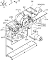
- the tape introduction / delivery mechanism 200 will be described with reference to FIGS. 7 to 10 are perspective views showing the configuration of the tape introduction / delivery mechanism 200.
- FIG. 8 and 9 show the tape introduction / delivery mechanism 200 in a state where one of the frames 201 provided in the tape introduction / delivery mechanism 200 is removed.
- FIG. 10 is an enlarged perspective view showing the vicinity of a connecting portion 204 provided in the tape introduction / delivery mechanism 200.
- the tape introduction / delivery mechanism 200 is disposed on the upstream side in the tape delivery direction H ⁇ b> 1 with respect to the second traveling path 52 configuring the upstream path in the tape traveling path 5, and introduces the component storage tape 100 into the second traveling path 52. I do.
- the tape introduction / delivery mechanism 200 includes a pair of frames 201, a first tape delivery unit 31 that forms a part of the tape delivery mechanism 3, a pair of tape holding units 202, an operation lever 203, a coupling unit 204, The above-described notification unit 23 attached to the main body 2 is provided.
- the tape delivery mechanism 3 including the first tape delivery unit 31 provided in the tape introduction and delivery mechanism 200 will be described with reference to FIGS.
- the tape sending mechanism 3 includes a first tape sending unit 31, a second tape sending unit 32, and a third tape sending unit 33.
- the first tape sending unit 31 constitutes a part of the tape introducing / sending mechanism 200
- the second tape sending unit 32 and the third tape sending unit 33 receive the component storage tape 100 sent by the tape introducing / sending mechanism 200.
- a tape receiving and sending mechanism is configured.
- the tape receiving and sending mechanism configured by the second tape sending unit 32 and the third tape sending unit 33 receives the component storage tape 100 introduced into the tape running path 5 by the tape introduction and delivery mechanism 200, and The component storage tape 100 is sent out along the tape running path 5 so that each of the component storage sections 101a sequentially passes the component removal position 21.
- the first tape feeding section 31 forms a part of the tape introduction / feeding mechanism 200, and is arranged on the upstream side in the tape feeding direction H1 with respect to the second running path 52 forming the upstream path in the tape running path 5. You.
- the first tape sending section 31 sends out the component storage tape 100 toward the second running path 52 of the tape running path 5 with the leading end being a free end. Thereby, the component storage tape 100 is introduced into the second running path 52 of the tape running path 5.
- the component storage tape 100 introduced into the second traveling path 52 by the first tape sending unit 31 travels on the first traveling path 51 via the second traveling path 52.
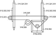
- the first tape sending section 31 includes a pair of first sprockets 311, a pair of first worm wheels 312, a pair of first worms 313, a first servo motor 314, a first belt 315, and a first tension. And a roller 316.
- the pair of first sprockets 311 are disk-shaped sprockets that are supported by the pair of frames 201 (see FIG. 7) so as to be rotatable about an axis extending in the X-axis direction (tape width direction H2).
- the pair of frames 201 constitute a part of the tape introduction / delivery mechanism 200.
- the pair of first sprockets 311 includes a plurality of teeth 311a arranged at predetermined intervals in the circumferential direction.
- the teeth 311a of the pair of first sprockets 311 can be respectively fitted with holes 101b formed at both ends of the carrier tape 101 of the component storage tape 100 in the tape width direction H2.
- a pair of first sprockets 311 has a built-in one-way clutch that transmits rotational force in only one direction. That is, the pair of first sprockets 311 rotate only when the first servomotor 314 rotates so as to send the component storage tape 100 in the tape sending direction H1, and the first servomotor 314 rotates in the opposite direction. Even if it does not rotate.
- the present invention is not limited to the configuration in which the one-way clutch is incorporated in the pair of first sprockets 311.
- One pair of the first sprockets 311 enables the component storage tape 100 to be sent in the tape sending direction H1.
- the configuration may be such that the rotation of the first servomotor 314 is controlled so as to rotate only in the direction.
- the pair of first worm wheels 312 are worm gears provided coaxially with each of the pair of first sprockets 311.
- Each of the pair of first worms 313 is a screw-shaped gear that meshes with each of the pair of first worm wheels 312.
- the first servomotor 314 is a drive source that generates a driving force for rotating the pair of first sprockets 311.
- the first servo motor 314 has a motor output shaft 314a for outputting a driving force.
- the first belt 315 is an endless belt, is stretched between the motor output shaft 314a and the pair of first worms 313, and runs around by the first servomotor 314 being rotationally driven.
- the first tension roller 316 is a roller that contacts the outer peripheral surface of the first belt 315 and applies tension to the first belt 315.
- the rotational driving force of the first servomotor 314 is transmitted to the pair of first worm wheels 312 via the first belt 315 and the pair of first worms 313, As a result, the pair of first worm wheels 312 rotate.
- the pair of first worm wheels 312 rotates
- the pair of first sprockets 311 rotate in conjunction with the rotation.
- the component storage tape 100 including the carrier tape 101 having the hole 101b that fits with the teeth 311a of the first sprocket 311 is sent out.
- the second tape sending unit 32 is disposed downstream of the first tape sending unit 31 in the tape sending direction H1.
- the second tape sending section 32 is disposed at the downstream end of the first running path 51 of the tape running path 5 in the tape sending direction H1, in other words, at the upstream end of the third running path 53 in the tape sending direction H1.
- the second tape sending unit 32 receives the component storage tape 100 that is sent by the first tape sending unit 31 and travels on the first travel path 51, and sends out the component storage tape 100 toward the component pickup position 21. . Thereby, the second tape sending unit 32 causes the component storage tape 100 to travel on the third travel path 53.
- the second tape sending unit 32 sends out the component storage tape 100 intermittently so that the center of the component storage unit 101a coincides with the component take-out position 21.
- the second tape sending unit 32 includes a pair of second sprockets 321, a pair of second worm wheels 322, a pair of second worms 323, a second servo motor 324, A second belt 325 and a second tension roller 326 are included.
- the pair of second sprockets 321 are disk-shaped sprockets supported by the apparatus main body 2 so as to be rotatable around an axis extending in the X-axis direction (tape width direction H2).
- the pair of first sprockets 321 include a plurality of teeth 321a arranged at predetermined intervals in the circumferential direction.
- the tooth portions 321a located on the + Z side in the Z-axis direction are exposed from the upper end surfaces of the pair of guide walls 41.
- the teeth 321a of the pair of second sprockets 321 can be respectively fitted with holes 101b formed at both ends of the carrier tape 101 of the component storage tape 100 in the tape width direction H2.
- the pair of second worm wheels 322 are worm gears provided coaxially with the pair of second sprockets 321, respectively.
- Each of the pair of second worms 323 is a screw-shaped gear that meshes with each of the pair of second worm wheels 322.
- the second servo motor 324 is a driving source that generates a driving force for rotating the pair of second sprockets 321.
- the second servo motor 324 has a motor output shaft 324a for outputting a driving force.
- the second belt 325 is an endless belt, is stretched between the motor output shaft 324a and the pair of second worms 323, and runs around by the second servomotor 324 being rotationally driven.
- the second tension roller 326 is a roller that comes into contact with the outer peripheral surface of the second belt 325 and applies tension to the second belt 325.
- the rotational driving force of the second servo motor 324 is transmitted to the pair of second worm wheels 322 via the second belt 325 and the pair of second worms 323, As a result, the pair of second worm wheels 322 rotate.
- the pair of second worm wheels 322 rotates
- the pair of second sprockets 321 rotates in conjunction with the rotation.
- the component storage tape 100 including the carrier tape 101 having the holes 101b fitted with the teeth 321a of the second sprocket 321 is sent out.
- the leading end of the component storage tape 100 delivered by the first tape delivery unit 31 reaches the pair of second sprockets 321, and the hole 101 b of the carrier tape 101 at the leading end of the component storage tape 100 is connected to the pair of second sprockets 321.
- the first servomotor 314 stops.
- the rotation shaft of the first sprocket 311 stops, but the one-way clutch interposed between this rotation shaft and the first sprocket 311 enables the rotation of the first sprocket 311 even if the rotation shaft does not rotate.
- One sprocket 311 can rotate in conjunction with the movement of the component storage tape 100 sent out by the rotation of the pair of second sprockets 321.
- the third tape sending section 33 is arranged at the downstream end of the horizontal area 531 in the tape running direction H1 in the third running path 53 of the tape running path 5. That is, the third tape sending unit 33 is provided near the component pick-up position 21 on the downstream side of the second tape sending unit 32 in the tape sending direction H1.
- the third tape sending unit 33 sends out the component storage tape 100 in cooperation with the second tape sending unit 32.
- the third tape sending unit 33 receives the component storage tape 100 that is sent by the second tape sending unit 32 and travels on the third travel path 53, and passes the component storage tape 100 through the component removal position 21. Send out.
- the third tape sending section 33 By arranging the third tape sending section 33 near the component pick-up position 21 and receiving the component storage tape 100 by the third tape sending section 33, the third tape sending section 33 is positioned with high precision with respect to the component pick-up position 21. In this state, the component storage tape 100 can be sent out.
- the third tape sending section 33 includes a pair of third sprockets 331 and a pair of third worm wheels 332.
- the above-mentioned “the third tape sending section 33 is located near the component take-out position 21” means that the component take-out position 21 is within a range of the pair of third sprockets 331 in the tape sending direction H1 when viewed from the X-axis direction. This means that the third tape sending unit 33 is arranged so as to be located.
- the component take-out position 21 When viewed from the X-axis direction, the component take-out position 21 may be directly above the tops (uppermost ends) of the pair of third sprockets 331, or may be Y-axis from directly above the tops of the pair of third sprockets 331. The position may be shifted in the direction.
- the component take-out position 21 is set to a position shifted in the Y-axis direction from directly above the tops of the pair of third sprockets 331, it is preferable to set a position shifted to the upstream side from the downstream side in the tape sending direction H1.
- the pair of third sprockets 331 are disk-shaped sprockets that are supported by the apparatus main body 2 so as to be rotatable around an axis extending in the X-axis direction (tape width direction H2).
- the pair of third sprockets 331 includes a plurality of teeth 331a arranged at predetermined intervals in the circumferential direction.
- the tooth portions 331a located on the + Z side are exposed from the upper end surfaces of the pair of guide walls 41.
- the teeth 331a of the pair of third sprockets 331 can be fitted into holes 101b formed at both ends of the carrier tape 101 of the component storage tape 100 in the tape width direction H2.
- the pair of third worm wheels 332 are worm gears provided coaxially with the pair of third sprockets 331, respectively. Each of the pair of third worm wheels 332 meshes with each of the pair of second worms 323.
- the rotational driving force of the second servomotor 324 is transmitted to the second tape 325 via the second belt 325 and the pair of second worms 323. Is transmitted to the third worm wheel 332, whereby the pair of third worm wheels 332 is rotated.
- the pair of third worm wheels 332 rotates, the pair of third sprockets 331 rotates in conjunction with the rotation.
- the pair of second sprockets 321 and the pair of third sprockets 331 are driven by the same second servomotor 324, and rotate at the same rotation speed.
- the component storage tape 100 including the carrier tape 101 having the holes 101b fitted with the teeth 331a of the third sprocket 331 is sent out.
- the pair of frames 201 are arranged opposite to each other at a predetermined interval in the X-axis direction (tape width direction H2), and extend in the Y-axis direction (tape sending direction H1). Shaped member.
- Each of the pair of frames 201 has an opening 2011. The distance between the opposing inner surfaces of the pair of frames 201 is set to be larger than the tape width K2 of the component storage tape 100.
- FIGS. 7 to 9 show only the first sprocket 311 attached to the ⁇ X-side frame 201 among the pair of first sprockets 311.
- the component storage tape 100 is sent out toward the second running path 52 of the tape running path 5 by rotating the pair of first sprockets 311.
- the pair of tape holding units 202 are arranged to face each other at a predetermined interval in the X-axis direction (tape width direction H2) between the pair of frames 201.
- the pair of tape holding units 202 is disposed below the first sprocket 311 ( ⁇ Z side).
- the pair of tape holding units 202 respectively hold both ends of the component storage tape 100 sent out by the first tape sending unit 31 in the tape width direction H2.
- each of the pair of tape holding units 202 is formed in a long shape extending along the tape sending direction H1 (Y-axis direction).
- the component storage tape 100 can be suitably held by the pair of long tape holding portions 202.
- the operation lever 203 is an elongated lever member extending along the tape sending direction H1 (Y-axis direction), and is operated by an operator.
- the operation lever 203 rotates around a first rotation axis J1 provided at the downstream end of the tape sending direction H1 when an operating force is applied to the operation area 2031 at the upstream end of the tape sending direction H1. It is supported by a pair of frames 201.
- the first rotation axis J1 extends in the tape width direction H2 (X-axis direction).
- the connecting portion 204 is a structure that connects each of the pair of tape holding portions 202 to the operation lever 203.
- the connecting portion 204 connects the pair of tape holding portions 202 to the operation lever 203 so as to be rotatable integrally with the operation lever 203.
- the connecting portion 204 is configured to hold the pair of tape holding portions 202 in such a manner that the pair of tape holding portions 202 can hold the component storage tape 100 and release the component storage tape 100 in response to the integral rotation with the operation lever 203.
- the pair of tape holding units 202 is connected to the operation lever 203 so that the posture is changed between the release posture and the release posture.
- FIG. 8 shows a state where the pair of tape holding units 202 are in the holding posture.
- FIG. 9 shows a state in which the pair of tape holding units 202 are in the holding release posture.
- the connecting portion 204 has a first connecting portion 2041 and a second connecting portion 2042.
- the first connecting portion 2041 connects the upstream end of the pair of long tape holding portions 202 in the tape sending direction H1 to the operation lever 203.
- the second connecting portion 2042 connects the downstream end of the pair of long tape holding portions 202 in the tape sending direction H1 to the operation lever 203.
- the pair of tape holding units 202 rotate integrally with the operation lever 203, so that the first tape sending unit 31 can send the component storage tape 100 and the first tape sending unit 31 can send the component storage tape 100.
- the storage tape 100 is displaced between a delivery release position where the delivery of the storage tape 100 is released.
- the delivery cancellation position is a position facing the opening 2011 of the pair of frames 201 below the delivery possible position ( ⁇ Z side).
- FIG. 8 shows a state in which the pair of tape holding units 202 are arranged at the sending-out possible position.
- FIG. 9 shows a state in which the pair of tape holding units 202 are arranged at the sending release position.
- the component supply device 1 provided with the tape introduction / delivery mechanism 200 can mount a plurality of component storage tapes 100.
- the component supply operation of the component supply device 1 is as follows. First, the operator holds a pair of tape holding tapes in which a component storage tape (hereinafter, referred to as a “preceding tape”) 100 in which component feeding is performed in advance in the component feeding device 1 is arranged at a sending-out possible position and takes a holding posture. The leading end of the preceding tape 100 is engaged with the first sprocket 311 while being held by the portion 202. Thereafter, the operator operates the operation unit 22 and inputs an instruction to rotate the first sprocket 311 to cause the leading tape 100 to be sent out toward the tape running path 5. Thereby, the preceding tape 100 is introduced into the tape running path 5. When the leading end of the preceding tape 100 introduced into the tape running path 5 reaches the second sprocket 321, the leading end is fitted with the second sprocket 321.
- the component supply operation of the component supply device 1 is started.
- the second sprocket 321 rotates, whereby the preceding tape 100 is intermittently sent out.
- the first sprocket 311 is configured to idle, and the leading tape 100 can be sent out by rotating the second sprocket 321.
- the operator pushes down the operation area portion 2031 at the upstream end of the operation lever 203 in the tape sending direction H ⁇ b> 1 to rotate the operation lever 203.
- the pair of tape holding units 202 connected to the operation lever 203 by the connection unit 204 is displaced downward from the delivery possible position to the delivery release position.
- the fitting of the preceding tape 100 with the first sprocket 311 is released.
- the leading tape 100 since the leading tape 100 is fitted to the second sprocket 321, even if the fitting to the first sprocket 311 is released, the leading tape 100 continues to be sent out by the second sprocket 321.
- the pair of tape holding units 202 are displaced from the delivery enabled position to the delivery release position by rotating integrally with the operation lever 203 in a holding posture capable of holding the preceding tape 100. I do. Then, the pair of tape holding units 202 assumes a holding release position in which the holding of the preceding tape 100 is released in a state where the tape holding units 202 are disposed at the delivery release position. As described above, when the preceding tape 100 is displaced downward so that the delivery by the first sprocket 311 is released after the leading tape 100 is introduced into the tape running path 5, both ends of the leading tape 100 in the tape width direction H2 are displaced. Are held by a pair of tape holding units 202.
- the operator moves the operation area 2031 at the upstream end of the operation lever 203 in the tape sending direction H1 upward.
- the pair of tape holding units 202 connected to the operation lever 203 by the connection unit 204 moves along the pair of frames 201 from the delivery release position to the delivery enabled position. Displaced upward.
- the pair of tape holding units 202 changes the posture from the holding release posture to the holding posture.
- the operator sends a component storage tape 100 (hereinafter, referred to as a “subsequent tape”) 100 following the preceding tape 100 to the sending tape.
- the leading end of the succeeding tape 100 is fitted to the first sprocket 311 while being held by the pair of tape holding portions 202 arranged in the possible positions and in the holding posture.
- the subsequent tape 100 can be mounted in a state where the components of the preceding tape 100 have not been cut. After that, when the supply of the components by the preceding tape 100 ends, the sending of the succeeding tape 100 is automatically started.
- the posture change is regulated by the pair of frames 201. For this reason, during the displacement between the delivery possible position and the delivery cancellation position, the pair of tape holding units 202 is restricted from extending outward from the opening 2011 of the pair of frames 201.
- the pair of tape holding units 202 of the adjacent component supply devices 1 can do.
- FIG. 10 shows only the structure of the second connecting portion 2042, the first connecting portion 2041 and the second connecting portion 2042 have the same connecting structure of the pair of tape holding portions 202 to the operation lever 203. It is.
- Each of the first connecting portion 2041 and the second connecting portion 2042 has a holder 204A, a movable shaft 204B, a pair of link members 204C, a biasing member 204D, a lower limit stopper member 204E, and a regulating plate 204F. .
- the holder 204A is fixed to the lower surface of the operation lever 203.
- the movable shaft 204B is a shaft that extends vertically (Z-axis direction) through the operation lever 203 and the holder 204A.
- the movable shaft 204B is provided movably in the vertical direction (Z-axis direction).
- the pair of link members 204C connect each of the pair of tape holding units 202 to the movable shaft 204B.
- Each of the pair of link members 204C is formed in a substantially L-shape in plan view when viewed from the Z-axis direction.
- Each of the pair of link members 204C has a fulcrum 204C1, a power point 204C2, and an action point 204C3.
- the force point portion 204C2 in a plan view seen from the Z-axis direction, is disposed at the center in the tape width direction H2 (X-axis direction), and the fulcrum portion 204C1 is positioned in the tape width direction H2 (X-axis direction). ),
- the action point portion 204C3 is disposed between the fulcrum portion 204C1 and the force point portion 204C2.
- the fulcrum 204C1 is fixed to the holder 204A so as to be rotatable around the second rotation axis J2.
- the second rotation axis J2 is a shaft extending in the tape sending direction H1 (Y-axis direction).
- the power point portion 204C2 is fixed to the movable shaft 204B so as to be rotatable around the third rotation axis J3.
- the third rotation axis J3 is a shaft part parallel to the second rotation axis J2. That is, the third rotation axis J3 extends in the tape sending direction H1 (Y-axis direction).
- the power point portion 204C2 has an elongated through hole 204CC when viewed from the Y-axis direction, and the third rotation axis J3 is inserted into the through hole 204CC.
- the action point section 204C3 is connected to the pair of tape holding sections 202.
- the biasing member 204D is a member that is attached to the holder 204A and biases the movable shaft 204B downward.
- the biasing member 204D is realized by, for example, a coil spring member wound around the movable shaft 204B.
- the pair of frames 201 releases the restriction on the change of the posture, and the pair of tape holding units 202 is disposed at the delivery release position facing the opening 2011, the urging member 204D is pressed by the pair of link members 204C.
- the downward movement ( ⁇ Z side) of the movable shaft 204B due to the urging force is input to the power point portion 204C2.
- the action point portion 204C3 swings about the fulcrum portion 204C1, and changes the posture of the pair of tape holding portions 202 from the holding posture to the holding releasing posture.
- the pair of tape holding units 202 is displaced from the release position to the transmittable position with the rotation of the operation lever 203, the pair of frames 201 The regulating force acts.
- the restricting force of the pair of frames 201 acting on the pair of tape holding portions 202 is transmitted to the movable shaft 204B via the pair of link members 204C.
- the movable shaft 204B moves upward (+ Z side) against the urging force of the urging member 204D.
- the pair of tape holding units 202 changes the posture from the holding release posture to the holding posture.
- a lower limit stopper member 204E provided in each of the first connecting portion 2041 and the second connecting portion 2042 is fixed to the upper end of the movable shaft 204B and determines the lower limit position of the movable shaft 204B that moves in the vertical direction (Z-axis direction). It is a member that regulates. Accordingly, in the pair of link members 204C, the amount of movement to the lower side ( ⁇ Z side) of the movable shaft 204B input to the force point portion 204C2 is defined, so that the action point portion 204C3 around the fulcrum portion 204C1 is defined. The swing amount is defined. For this reason, the posture change of the pair of tape holding units 202 by the pair of link members 204C is performed stably.
- the restricting plate 204F provided in each of the first connecting portion 2041 and the second connecting portion 2042 is a long plate extending along the tape sending direction H1 (Y-axis direction).
- the regulating plate 204F is fixed to the lower end of the movable shaft 204B so as to face the component storage tape 100 held by the pair of tape holding units 202 on the upper side (+ Z side). In other words, in a state where the pair of tape holding units 202 is arranged at the position where the tape can be sent out, the regulating plate 204F controls the upward displacement (+ Z side) of the component storage tape 100 held by the pair of tape holding units 202. regulate.
- the running posture of the component storage tape 100 is stabilized.
- the movable shaft 204B moves downward ( ⁇ Z side), and the pair of tape members is held by the operation of the pair of link members 204C based on the movement.
- the posture of the unit 202 is changed from the holding posture to the holding releasing posture.
- the regulating plate 204F moves downward (-Z side) integrally with the movable shaft 204B.
- the regulating plate 204F can push down the component storage tape 100 that has been released from being held by the pair of tape holding units 202 in the holding release posture. Therefore, the component storage tape 100 is reliably separated from the pair of tape holding units 202.
- the tape introduction / delivery mechanism 200 includes a projecting piece 205 projecting from the lower surface of the operation lever 203 and a tape supporting member attached around the opening 2011 in the pair of frames 201.
- Unit 206 The protruding piece 205 pushes the component storage tape 100 released from being held by the pair of tape holding units 202 in the holding release posture, to the lower side ( ⁇ Z side) in accordance with the rotation of the operation lever 203.
- the tape supporting portion 206 supports the component storage tape 100 while restricting the upward displacement (+ Z side) of the component storage tape 100 pushed down by the projecting piece 205.
- the component storage tape 100 released from being held by the pair of tape holding units 202 arranged at the sending release position. Is elastically deformed such that the upstream end side of the tape sending direction H1 hangs down.
- the component storage tape 100 moves upward due to its own elasticity. Try to get up.
- a tape introduction / delivery mechanism 200 including a projecting piece 205 projecting from the lower surface of the operation lever 203 and a tape supporting portion 206 is provided.
- the projecting piece 205 pushes the component storage tape 100 released from holding by the pair of tape holding units 202 downward ( ⁇ Z side).
- the tape supporting portion 206 supports the component storage tape 100 while restricting the upward displacement (+ Z side) of the component storage tape 100 pushed down by the projecting piece 205.
- the component storage tape 100 released from holding by the pair of tape holding units 202 can be reliably separated from the pair of tape holding units 202.
- the tape introduction / delivery mechanism 200 further includes a pair of tape introduction guide portions 207 attached to the downstream ends of the pair of frames 201 in the tape delivery direction H1.
- Each of the pair of tape introduction guide portions 207 has a tape introduction guide surface 2071 that guides the introduction of the component storage tape 100 sent out by the first sprocket 311 into the tape running path 5, and an upstream of the tape introduction guide surface 2071.
- an introduction inclined surface 2072 connected to the side.
- the tape introduction guide surface 2071 and the second traveling path 52 of the tape traveling path 5 (the upper end surfaces of the pair of guide walls 41) are located on the same plane.
- the tape sending direction H1 between the downstream edge of the pair of tape holding portions 202 in the tape sending direction H1 and the upstream edge of the tape introducing guide surface 2071 of the pair of tape introducing guide portions 207 in the tape sending direction H1. Is set to be equal to or longer than the distance between the centers of the adjacent component storage portions 101a in the component storage tape 100.
- the component storage tape 100 sent out by the first sprocket 311 has a pair of tape introduction guides 207 with both ends in the tape width direction H2 held by a pair of tape holding units 202 arranged at a sendable position.
- the tape is guided into the tape running path 5 while being guided along the guide surface 2071.
- the component storage tape 100 introduced into the tape traveling path 5 is intermittently sent out toward the component take-out position 21 by the second sprocket 321 arranged on the tape traveling path 5.
- the pair of tape holding units 202 holding the component storage tape 100 shifts from the delivery enabled position to the delivery release position in order to release the holding of the component storage tape 100. Displaced.
- the pair of tape holding units 202 is displaced from the sending-possible position to the sending-release position with the rotation of the operation lever 203 around the first rotation axis J1 provided at the downstream end in the tape sending direction H1. . That is, the pair of tape holding units 202 is inclined downward ( ⁇ Z side) from the downstream end to the upstream end in the tape sending direction H1 with the displacement from the sending enable position to the sending cancel position. Therefore, the component storage tape 100 introduced into the tape running path 5 along the tape introduction guide surface 2071 of the pair of tape introduction guide portions 207 causes the tape introduction guide portion 207 to be displaced by the displacement of the pair of tape holding portions 202. The tape is bent at a region between the tape holding unit 202 and the tape holding unit 202.
- the component storage tape 100 be bent at a region between the adjacent component storage portions 101a.
- the pair of tape introduction guide units 207 and the pair of tape holding units 202 are arranged close to each other in the tape sending direction H1
- the pair of tape holding units 202 is moved from the sending possible position to the sending cancel position.
- the timing of the downward displacement is such that the region between the adjacent component storage portions 101a in the component storage tape 100 intermittently sent out by the second sprocket 321 is between the tape introduction guide portion 207 and the tape holding portion 202.
- the timing is limited to the position in the gap.
- the downstream edges of the pair of tape holding portions 202 in the tape delivery direction H1 and the upstream edges of the pair of tape introduction guide portions 207 on the tape introduction guide surface 2071 in the tape delivery direction H1. Is set to be equal to or longer than the distance between the centers of the adjacent component storage units 101a in the component storage tape 100.
- the region between the adjacent component storage portions 101a in the component storage tape 100 intermittently sent out by the second sprocket 321 always fits into the gap between the tape introduction guide portion 207 and the tape holding portion 202. Will exist. Therefore, regardless of the timing at which the pair of tape holding units 202 is displaced downward from the sendable position to the send release position, the component storage tape 100 is located in the area between the adjacent component storage units 101a. The part is suitably folded.
- the component storage tape 100 introduced into the tape running path 5 by the tape introduction / delivery mechanism 200 is subjected to component exposure processing by the component exposure unit 6.
- the component exposure portion 6 will be described with reference to FIG. 12 in addition to FIG.
- FIG. 12 is a perspective view illustrating a configuration of the component exposure unit 6 provided in the component supply device 1.
- the component exposing portion 6 raises the cover tape 102 of the component storage tape 100 running on the tape running path 5 starting from the joint 103 with the carrier tape 101, and the side end of the component storage tape 100 in the tape width direction H2.
- a component exposing process is performed in which the component E2 is exposed in the component storage unit 101a by spreading the component E2 outward and bending it downward ( ⁇ Z side).
- the component exposure section 6 includes a cover tape start-up section 61, a cover tape pre-processing section 62, and a cover tape post-processing section 63.
- the cover tape rising section 61 is disposed on the first traveling path 51 in the tape traveling path 5.
- the cover tape start-up section 61 applies the cover tape 102 to the carrier tape 101 so that the start-up amount of the cover tape 102 with respect to the carrier tape 101 in the component storage tape 100 running on the first running path 51 continuously increases.
- a start-up process is performed to start up.
- the cover tape pre-processing unit 62 is disposed on the second running path 52 of the tape running path 5 between the pair of guide walls 41.
- the cover tape pre-processing unit 62 performs pre-processing for cutting the cover tape 102 prior to the start-up process by the cover tape start-up unit 61.
- the cover tape post-processing section 63 is disposed on the first traveling path 51 of the tape traveling path 5 above the cover tape rising section 61 (+ Z side).
- the cover tape post-processing unit 63 removes the cover tape 102 raised by the cover tape rising unit 61 so as to open the component storage unit 101a at each side edge of the component storage tape 100 on both sides in the tape width direction H2.
- a post-processing is performed to spread outward and bend downward ( ⁇ Z side).
- FIG. 13 is a perspective view illustrating a configuration of the cover tape pre-processing unit 62 of the component exposure unit 6.
- FIG. 14 is a perspective view showing a configuration of the cover tape rising section 61 of the component exposure section 6.
- FIG. 15 is a perspective view illustrating a configuration of the cover tape post-processing unit 63 of the component exposure unit 6.
- FIG. 16 is a side view of the cover tape post-processing unit 63.
- FIG. 17 is a plan view of the cover tape post-processing unit 63 as viewed from above.
- the cover tape pre-processing unit 62 is disposed on the second traveling path 52 of the tape traveling path 5 between the pair of guide walls 41 as described above.
- the cover tape pre-processing unit 62 covers the component storage tape 100 that is sent out by the first tape sending unit 31 of the tape introduction / feeding mechanism 200 and runs on the second running path 52 with the free end.
- pre-processing for cutting the cover tape 102 is performed prior to the start-up processing of the cover tape 102 by the tape start-up unit 61.
- the cover tape pre-processing unit 62 includes an insertion member 621, a cover tape cutting unit 622, and a support unit 623.
- the insertion member 621 is delivered by the first tape delivery unit 31 with the free end at the leading end, and is inserted between the cover tape 102 and the carrier tape 101 in the component storage tape 100 traveling on the second traveling path 52. Is a member to be inserted into.
- the insertion member 621 is formed in a flat plate shape.
- the insertion member 621 includes a base 6211 and an insertion tip 6212 that is continuous with the upstream end of the base 6211 in the tape sending direction H1.
- a lid member 54 described later is connected to the downstream end 6211a of the base 6211 of the insertion member 621 in the tape sending direction H1.
- the insertion distal end portion 6212 rises with respect to the base portion 6211 so as to incline upward (+ Z side) from a connection portion with the base portion 6211 toward a distal end edge 6212 a serving as an upstream end in the tape sending direction H1. It is inclined.
- the base 6211 in a state where the insertion member 621 is inserted between the cover tape 102 and the carrier tape 101, the base 6211 is substantially parallel to the cover tape 102, and the insertion front end 6212 is separated from the carrier tape 101 with an interval, and It is inclined toward the 102 side.
- the first tape delivery unit 31 can use the component with the insertion member 621 inserted between the cover tape 102 and the carrier tape 101.
- the storage tape 100 is sent out, it is possible to prevent the insertion distal end portion 6212 from contacting the storage portion connection area portion of the carrier tape 101 located between the adjacent component storage portions 101a. Therefore, the good running property of the component storage tape 100 is maintained, and the component E2 can be efficiently supplied to the component take-out position 21.
- the insertion distal end portion 6212 of the insertion member 621 is formed in a tapered shape tapering in the width direction toward the distal end edge 6212a.
- the insertion member 621 is supported by the support 623.
- the support portion 623 is arranged on the upper surface of a lid member 54 described later connected to the downstream end 6211a of the base portion 6211 of the insertion member 621 in the tape sending direction H1, and is fixed to the apparatus main body 2. . With such a configuration, the support portion 623 supports the insertion member 621 via the lid member 54.
- the cover tape cutting section 622 is sent by the first tape sending section 31 with the leading end being a free end, and cuts the cover tape 102 of the component storage tape 100 running on the second running path 52.
- the cover tape cutting section 622 cuts a predetermined position (for example, a center position) between both ends in the width direction of the cover tape 102.
- the cut portion 102a (see FIG. 12) of the cover tape 102 cut by the cover tape cutting portion 622 extends linearly along the tape running path 5.
- the cover tape cutting section 622 includes a blade section 6221 for cutting the cover tape 102 and a holding section 6222.
- the holding portion 6222 has a holding surface 6222a for holding the blade portion 6221 such that the blade edge is exposed.
- the cover tape cutting portion 622 is formed such that the surface of the holding portion 6222 on the side opposite to the holding surface 6222a in the region portion 6222b on the upstream side in the tape sending direction H1 abuts on the upper surface 6211b of the base 6211 of the insertion member 621. It is supported by the support part 623 via the member 54. In the cover tape cutting section 622, the blade section 6221 held on the holding surface 6222a of the holding section 6222 faces the upper side (+ Z side). With such a configuration, when the component storage tape 100 traveling on the second traveling path 52 passes through the cover tape cutting section 622, the insertion member is inserted between the upstream end 6222c of the cover tape cutting section 622 and the carrier tape 101. 621 will be interposed.
- the holding surface 6222a is an inclined surface that slopes downward from the downstream to the upstream in the tape sending direction H1. Accordingly, when the component storage tape 100 travels on the second travel path 52 and passes through the cover tape cutting portion 622, the component storage tape 100 is guided along the holding surface 6222a of the holding portion 6222 that is inclined. As a result, the running resistance when the component storage tape 100 passes through the cover tape cutting section 622 can be reduced.
- the insertion member 621 may be configured to be supported by the support portion 623 via the cover member 54 so as to be able to swing around a predetermined axis J1 extending in the X-axis direction (tape width direction H2).
- the cover tape cutting section 622 is configured such that at least a region 6222 b of the holding section 6222 on the upstream side in the tape sending direction H ⁇ b> 1 is fixed to the base 6211 of the insertion member 621 so as to be able to swing in conjunction with the swing of the insertion member 621. Is in contact with the upper surface 6211b.
- the insertion member 621 and the cover tape cutting portion 622 inserted between the cover tape 102 and the carrier tape 101 are attached to the component storage tape. It becomes possible to swing according to the bending of 100. Therefore, the contact of the insertion distal end portion 6212 of the insertion member 621 with the storage portion connection region portion of the carrier tape 101 can be stably suppressed.
- the cover tape rising section 61 is disposed on the first traveling path 51 of the tape traveling path 5 between the pair of guide walls 41.
- the cover tape rising section 61 contacts the cut portion 102a of the cover tape 102 cut by the cover tape cutting section 622 in the component storage tape 100 traveling on the first traveling path 51, thereby causing the cover tape 102 to be moved.
- the carrier tape 101 is raised upward.
- the cover tape start-up unit 61 includes a start-up inducing unit 611 and a start-up amount adjusting unit 612.
- the start-up inducing section 611 forms an upstream portion of the cover tape start-up section 61 in the tape sending direction H1.
- the start-up inducing section 611 has a contact start point P1 serving as a start point of contact with the cover tape 102, and induces the start of the cover tape 102 with respect to the carrier tape 101 from the contact start point P1.
- the cover tape rising section 61 is arranged such that the contact starting point P1 of the rising inducing section 611 is located at the center between the pair of guide walls 41. In other words, the contact starting point P1 of the start-up inducing section 611 is located on the cut portion 102a of the cover tape 102 cut by the cover tape cutting section 622. In the cover tape start-up section 61, the start-up inducing section 611 is fixed to the lid member 54 described later.
- the start-up amount adjustment unit 612 is connected to the downstream end of the start-up inducing unit 611 in the tape sending direction H1.
- the rising amount adjustment unit 612 continuously increases the rising amount of the cover tape 102 with respect to the carrier tape 101 as the component storage tape 100 travels on the first travel path 51.
- the start-up amount adjusting unit 612 includes a pair of start-up adjusting pieces 6121 and 6122.
- Each of the pair of rise adjusting pieces 6121 and 6122 is a plate-shaped member extending from a connection portion with the rise inducing portion 611 so as to approach each of the pair of guide walls 41.
- the downstream end in the tape sending direction H1 abuts on the joint 103 with the carrier tape 101 at both ends of the cover tape 102 in the tape width direction H2.
- each of a pair of rising adjustment pieces 6121 and 6122 constituting the rising amount adjustment unit 612 includes a first adjustment piece 6123 and a tape sending direction of the first adjustment piece 6123.
- a second adjustment piece 6124 connected to the downstream end of the H1 via the connection member 613.
- the second adjustment piece 6124 is connected to the first adjustment piece 6123 such that the second adjustment piece 6124 can swing around the connection member 613.
- the pair of rising adjustment pieces 6121 and 6122 having such a configuration including the first adjustment piece 6123 and the second adjustment piece 6124 corresponds to a change in the running behavior of the component storage tape 100 on the first running path 51. Swingable. Therefore, a decrease in the stability of the startup process of the cover tape 102 by the pair of startup adjustment pieces 6121 and 6122 is prevented.
- the first traveling path 51 in which the cover tape rising section 61 is disposed includes the first curved area 511 on the most upstream side in the tape sending direction H1 and the downstream of the first curved area 511 in the tape sending direction H1. And a third curved region 513 that continues to the downstream side of the second curved region 512 in the tape feeding direction H1.
- the first traveling path 51 When viewed from the X-axis direction (tape width direction H2), the first traveling path 51 has a different bending direction in the Z-axis direction (vertical direction) between the first curved region 511 and the second curved region 512, and the sign of the curvature is different. Change.
- the component storage tape 100 travels along the first traveling path 51, the component storage tape 100 is moved in the Z-axis direction (when passing through the first curved region 511 and when passing through the second curved region 512). With respect to (vertical direction), a force to bend in the opposite direction acts.
- the cover tape rising section 61 when the cover tape rising section 61 is disposed over the first curved area 511 and the second curved area 512 in the first traveling path 51, the cover tape rising section 61 stabilizes the processing of rising the cover tape 102. May be reduced.
- the cover tape rising section 61 is configured such that the contact start point P1 of the rising inducing section 611 is on or near the boundary line S1 between the first curved area 511 and the second curved area 512. It is arranged so that it may be located. In such a configuration, the cover tape riser 61 is located at or near the boundary S1 between the first curved region 511 and the second curved region 512 because the contact start point P1, which is the most upstream end thereof, is located. Instead of being arranged over the first curved region 511 and the second curved region 512, they are arranged in the second curved region 512.
- the stability of the process of starting up the cover tape 102 by the cover tape start-up section 61 is prevented from lowering.
- the pair of rising adjustment pieces 6121 and 6122 extend over the second curved region 512 and the third curved region 513 of the first traveling path 51 in the tape sending direction H1.
- the component storage tape 100 travels in the first curved area 511 and the second curved area 512 of the first traveling path 51, it travels while bending.
- the component storage tape 100 traveling on the first travel path 51 is sent out by the first tape delivery unit 31 of the tape introduction / delivery mechanism 200 disposed on the upstream side of the first travel path 51, Deflection during traveling with the inflection point between the first curved area 511 and the second curved area 512 as a boundary between the case where the tape is sent by the second tape sending unit 32 arranged on the downstream side of the one traveling path 51
- the direction changes, and the running behavior on the first running path 51 changes.
- the component storage tape 100 delivered by the first tape delivery unit 31 bends upward (+ Z side) in the first curved area 511 and bends downward ( ⁇ Z side) in the second curved area 512.
- the component storage tape 100 sent out by the second tape sending unit 32 bends downward ( ⁇ Z side) in the first curved area 511 and bends upward (+ Z side) in the second curved area 512.
- the cover tape rising section 61 of the present embodiment as described above, only the rising inducing section 611 is fixed to the lid member 54 described later, and the second adjusting piece 6124 is connected to the first adjusting piece 6123. On the other hand, they are connected such that they can swing around the connection member 613. Thereby, the cover tape rising section 61 can swing in response to a change in the running behavior of the component storage tape 100 on the first running path 51. Therefore, the stability of the process of starting up the cover tape 102 by the cover tape start-up section 61 is prevented from lowering.
- the third curved region 513 of the second curved region 512 in which the cover tape rising portion 61 is disposed in the first traveling path 51 and which is continuous with the downstream side in the tape sending direction H1 is formed in a shape that is upwardly convex.
- the second tape sending unit 32 including the pair of second sprockets 321 is disposed at the most downstream end of the third curved region 513 in the tape sending direction H1.
- the reason why the shape of the third region 513 is upwardly convex is that the hole of the carrier tape 101 at the tip end of the component storage tape 100 which is sent by the first tape sending unit 31 and travels in the third curved region 513. This is for improving the fitting property when the portion 101b is fitted to the tooth portion 321a of the pair of second sprockets 321.
- the lid member 54 is a member that covers at least a part of each opening of the component storage unit 101a of the component storage tape 100 after the exposure processing for exposing the component E2 in the component storage unit 101a by the component exposure unit 6.
- the component supply device 1 is configured to include the lid member 54, the component E2 protrudes from the component storage unit 101a when the component storage tape 100 after the exposure processing is sent out by the tape sending unit 3, so that the cover member can be used. 54. Therefore, it is possible to stably supply components to the component pick-up position 21 by the component supply device 1.
- the cover member 54 extends along the tape running path 5 from the downstream end 6211a of the base 6211 of the insertion member 621 in the tape sending direction H1 to the component take-out position 21.
- the lid member 54 connected to the downstream end 6211 a of the base 6211 of the insertion member 621 is inserted between the cover tape 102 and the carrier tape 101 of the component storage tape 100 delivered by the tape delivery mechanism 3.
- the component storage unit 101a is covered along the tape running path 5. Therefore, the cover member 54 has a function of guiding the running of the component storage tape 100 sent out by the tape sending mechanism 3 in a state inserted between the cover tape 102 and the carrier tape 101.
- the lid member 54 is a member having flexibility.
- the cover member 54 when the component storage tape 100 travels while flexing along the first curved region 511 and the second curved region 512 of the first traveling path 51, the cover member 54 is subjected to bending of the component storage tape 100. It will bend accordingly.
- the frictional force is increased due to the contact between the cover member 54 covering the component storage portion 101a and the carrier tape 101. Can be suppressed. Therefore, the running resistance when the component storage tape 100 runs on the tape running path 5 can be reduced.
- the lid member 54 be formed of metal so as not to generate static electricity.
- the lid member 54 may have a configuration in which a conductive layer is formed on the surface of a base material made of plastic or the like.
- the cover tape post-processing section 63 is disposed above the cover tape rising section 61 (+ Z side).
- the cover tape post-processing unit 63 removes the cover tape 102 started by the cover tape start-up unit 61 so that the component storage unit 101a is opened. Spread outward and bend downward (-Z side).
- the cover tape post-processing section 63 includes an upper regulating section 631 and a side regulating section 632, as shown in FIGS.
- the upper regulating section 631 is disposed to face the first traveling path 51 of the tape traveling path 5 with a gap on the upper side.
- the upper restricting portion 631 controls the cover tape 102 raised by the cover tape rising portion 61 so that the component storing portion 101a is opened while restricting the upward movement of the cover tape 102.
- a first post-processing is performed in which both sides of each side edge are spread outside.
- the gap between the upper regulating portion 631 and the first traveling path 51 of the tape traveling path 5 is set so as to become narrower from upstream to downstream in the tape sending direction H1.
- the upward regulating portion 631 increases the outward spread amount of the cover tape 102 toward each side edge on both sides in the tape width direction H2 according to the continuous increase of the rising amount by the rising amount adjusting portion 612. , The cover tape 102 can be spread outward. For this reason, it is possible to effectively open the component storage unit 101a, and it is possible to improve the takeout property of the component E2 at the component takeout position 21.
- the upper regulation portion 631 has an upper regulation start point P2 (see FIGS. 16 and 17) which is a start point of regulation of upward movement of the cover tape 102 raised by the cover tape rising portion 61.
- the upper regulation part 631 has a first upper regulation area 6311 and a second upper regulation area 6312 as shown in FIGS.
- the first upper regulation area 6311 faces the second curved area 512 of the first travel path 51, and extends obliquely downward from upstream to downstream in the tape sending direction H1.
- the second upper regulation area 6312 is continuous with the first upper regulation area 6311 on the downstream side in the tape sending direction H1.
- the second upper regulation area 6312 faces the third curved area 513 of the first traveling path 51 and extends horizontally along the tape sending direction H1.
- the gap between the first upper restriction area 6311 of the upper restriction section 631 and the second curved area 512 of the first travel path 51 is narrower in accordance with the downward inclination of the first upper restriction area 6311.
- the gap between the second upper restriction region 6312 of the upper restriction portion 631 and the third curved region 513 of the first traveling path 51 becomes narrower according to the curved shape that is convex above the third curved region 513. That is, the gap between the upper regulating portion 631 and the first traveling path 51 can be set to be narrower from upstream to downstream in the tape sending direction H1.
- the lower end of the second upper restriction region 6312 of the upper restriction portion 631 (the surface on the side facing the first travel path 51) is located at the downstream end in the tape sending direction H1.
- the auxiliary member 633 for adjusting the amount of rising is protruded.
- Each of the pair of rising amount adjusting auxiliary pieces 633 approaches the pair of guide walls 41 from the downstream ends of the pair of rising adjusting pieces 6121 and 6122 from the upstream to the downstream in the tape sending direction H1. It is a tabular protruding piece that extends.
- the separation distance along the tape width direction H2 between the pair of rising amount adjustment auxiliary pieces 633 gradually increases from upstream to downstream in the tape sending direction H1.
- the distance between the pair of rising amount adjustment auxiliary pieces 633 is larger than the distance between the pair of rising adjustment pieces 6121 and 6122 on the downstream side.
- the pair of rising adjustment auxiliary pieces 633 continuously increase the rising amount of the cover tape 102 on the downstream side of the pair of rising adjustment pieces 6121 and 6122.
- the side regulating sections 632 are arranged at both ends in the width direction of the upper regulating section 631 so as to face the side end faces of the component storage tape 100 from outside the pair of guide walls 41 in the tape width direction H2. Extending downward from each of them.
- the side restricting portion 632 moves the cover tape 102, which has been extended outward from the respective side edges on both sides in the tape width direction H2 of the component storage tape 100 by the upper restricting portion 632, downwardly while restricting the lateral movement.
- a second post-processing for bending is performed.
- the cover tape post-processing unit 63 is configured to be located within the second upper regulation region 6312 that extends. Thereby, when the cover tape 102 is bent downward from the side regulation start point P3, the buckling deformation of the carrier tape 101 can be suppressed.
- the tape running guide section 7 is arranged in a horizontal area 531 in the third running path 53 of the tape running path 5 on the downstream side of the component exposing section 6 in the tape feeding direction H1. That is, the tape running guide 7 is provided near the component take-out position 21.
- the tape running guide unit 7 guides the running of the component storage tape 100 on the third running path 53 toward the component take-out position 21 after the component exposing process by the component exposing unit 6.
- the tape running guide section 7 includes a guide main body 71 and an opening width defining member 72.
- the guide main body 71 forms a main body of the tape running guide section 7, and has an opening 711.
- the opening 711 opens in the component storage tape 100 traveling on the third travel path 53, facing the component storage portion 101 a opened by the component exposure processing of the component exposure portion 6.
- the opening 711 is formed in a rectangular shape having a predetermined length in the tape sending direction H1.
- the opening 711 is located immediately below the component take-out position 21. That is, the head unit 14 of the component mounter 10 takes out the component E2 supplied to the component removal position 21 by the component supply device 1 through the opening 711.
- the opening width defining members 72 are attached to both opening edges of the opening 711 of the guide main body 71 in the tape width direction H2, and define the opening width of the opening 711 in the tape width direction H2.
- the tape running guide 7 further includes a pair of tape introduction guides 73 and a pair of tape guides 74.
- Each of the pair of tape introduction guide portions 73 is a rod-shaped member extending along the tape sending direction H1.
- Each of the pair of tape introduction guide portions 73 is attached to the upstream side of the opening 711 in the guide main body 71 in the tape sending direction H1 with a space therebetween in the tape width direction H2.
- Each of the pair of tape introduction guide portions 73 guides the introduction of the cover tape 102 into the tape traveling guide portion 7 while restricting the displacement of the cover tape 102 inward in the tape width direction H2.
- Each of the pair of tape lead-out guides 74 is a rod-shaped member extending along the tape sending direction H1.
- Each of the pair of tape lead-out guides 74 is attached to the guide main body 71 at a position downstream of the opening 711 in the tape feeding direction H1 with a space therebetween in the tape width direction H2.
- Each of the pair of tape guide-out guides 74 guides the guide of the cover tape 102 from the tape running guide 7 while restricting the displacement of the cover tape 102 inward in the tape width direction H2.
- the component storage tape 100 is discharged from the component supply device 1.
- the component storage tape 100 that has passed through the tape running guide portion 7 is discharged from the component supply device 1 so as to hang downward.
- the component storage tape 100 is bent at the storage portion connection area portion between the adjacent component storage portions 101a in the carrier tape 101, and hangs downward.
- the component storage tape 100 tends to expand upward.
- the component storage tape 100 is discharged from the component supply device 1 through the tape discharge guide portion 8.
- the tape discharge guide section 8 is attached to the downstream end of the pair of guide walls 41 on the downstream side in the tape sending direction H1 on the downstream side of the tape running guide section 7 in the tape sending direction H1.
- the tape discharge guide 8 guides the discharge of the component storage tape 100 that has passed through the tape travel guide 7 to the downstream side.
- the tape discharge guide 8 restricts the upward and lateral movement of the component storage tape 100 by contacting the upper surface and the side end surface of the component storage tape 100 that has passed through the tape travel guide 7. Thereby, the tape discharge guide section 8 can suppress the upward bulging of the component storage tape 100 discharged from the component supply device 1.
- the tape is cut into strips by the tape cutting device 18.
- the cut pieces cut by the tape cutting device 18 fall in a predetermined collection path and are collected in a collection box.
- FIG. 18 is a block diagram illustrating an electrical configuration of the component supply device 1.
- the component supply device 1 further includes a control unit 9.
- the control unit 9 controls the operation of the component supply device 1, in particular, the tape sending operation of the tape sending mechanism 3.
- the control unit 9 controls the tape sending operation of the tape sending mechanism 3 based on the detection result of the presence / absence of the component storage tape 100 by the tape detecting unit, which is arranged at various parts of the component supply device 1.
- the component supply device 1 includes a set detection unit 24, an introduction detection unit 25, a first detection unit 26, and a second detection unit 27 as tape detection units.
- the set detection unit 24 is a tape detection unit that is arranged in the tape introduction / delivery mechanism 200 on the upstream side of the first tape transmission unit 31 in the tape transmission direction H1.
- the set detecting unit 24 detects the component storage tape 100 set so that the tip end is fitted to the first sprocket 311 of the first tape sending unit 31. More specifically, the set detection unit 24 is held by a pair of tape holding units 202 arranged in a sending-possible position and in a holding posture, and the component storage tape 100 in a state where the leading end is fitted to the first sprocket 311.
- the introduction detection unit 25 is a tape detection unit arranged at the most upstream end of the tape traveling path 5 in the tape sending direction H1.
- the introduction detection unit 25 detects the component storage tape 100 that has been transmitted by the first tape transmission unit 31 and has been introduced into the tape traveling path 5.
- the introduction detection unit 25 is disposed below the pair of tape holding units 202, and the holding of the component storage tape 100 is released by the pair of tape holding units 202 taking the holding release posture. , The component storage tape 100 is detected.
- the first detection unit 26 is a tape detection unit disposed at a predetermined position (first position) on the tape running path 5 on the upstream side of the second tape transmission unit 32 in the tape transmission direction H1. More specifically, the first detection unit 26 is configured to determine the reference length of the trailer unit set at the rear end of the component storage tape 100 along the tape running path 5 on the upstream side in the tape feeding direction H1 from the component removal position 21. L (see FIGS. 5A to 5C). The first detection unit 26 detects the component storage tape 100 sent out by the first tape sending unit 31 toward the second tape sending unit 32 before the leading end reaches the second tape sending unit 32.
- the second detection unit 27 is a tape detection unit disposed at a predetermined position (second position) between the first detection unit 26 and the component take-out position 21 on the tape running path 5.
- the second detection unit 27 is disposed between the second tape sending unit 32 and the third tape sending unit 33.
- the second detecting unit 27 detects the component storage tape 100 sent out toward the component pick-up position 21 by the second tape sending unit 32 before the leading end reaches the third tape sending unit 33.
- Each of the set detection unit 24, the introduction detection unit 25, the first detection unit 26, and the second detection unit 27 may be configured to include an optical tape detection sensor as a sensor for detecting the component storage tape 100
- the mechanical tape detection sensor is configured to include a dog that is displaced by abutting the leading end of the component storage tape 100 and a sensor unit that detects the displacement of the dog.
- a mechanical tape detection sensor By adopting a mechanical tape detection sensor, a wide variety of component storage tapes 100 such as those made of a transparent material having a light transmitting property and those made of an opaque material having no light transmitting property are suitable. Can be detected.
- a plurality of component storage tapes 100 can be mounted, and the subsequent tape 100 can be mounted in a state in which the component of the preceding tape 100 has not been cut.
- the control unit 9 controls the sending of the leading tape 100 and the succeeding tape 100 by the tape sending mechanism 3.
- the control unit 9 includes a microcomputer having a built-in storage device such as a ROM (Read Only Memory) for storing a control program and a flash memory for temporarily storing data.
- a control program for storing a control program
- a flash memory for temporarily storing data.
- the operation of the supply device 1 is controlled.
- the control unit 9 includes a communication unit 91, a tape travel distance calculation unit 92, an input / output control unit 93, a first transmission processing unit 94, a second transmission processing unit 95, a lever operation And a monitoring unit 96.
- the communication unit 91 is connected to the component mounter 10 so as to enable data communication, and receives the determination result information output from the component outage determination unit 19 provided in the component mounter 10.
- the component outage judging unit 19 of the component mounter 10 accepts the preceding tape 100 sent out by the first tape sending unit 31 by the second tape sending unit 32, and outputs the second tape sending unit 32 and the third tape sending unit 33.
- the preceding tape 100 which is intermittently sent out to the component pick-up position 21 by the interlocking operation, the last component E2 stored in the component storage portion 101a is taken out by the head unit 14 and the preceding tape 100 becomes out of component. Is determined.
- the component shortage determination unit 19 extracts the last component E2 by the head unit 14 and removes the preceding tape 100 Is determined.
- the component shortage determination unit 19 monitors the status of the removal of the component E2 from the component removal position 21 by the head unit 14, and when the removal of the component E2 by the head unit 14 is not succeeded a plurality of times consecutively, the component storage unit. It is detected that there is no component E2 in 101a, and it is determined that the preceding tape 100 is out of components.
- the component shortage determination unit 19 determines whether there is a component E2 in the component storage unit 101a based on an image that is captured by the camera and that indicates the component holding state of the head unit 14 after the component removal operation, and determines whether the component has run out. Then, the presence or absence of the component E2 in the component storage unit 101a is detected based on the detection result of the sensor for detecting the vacuum pressure, and the component exhaustion is determined. Alternatively, the component shortage determination unit 19 determines the presence or absence of the component E2 in the component storage unit 101a based on an image captured by the camera and indicating whether or not a component is present at the component removal position 21 and determines the component shortage. You may make it. In this case, the camera is attached to the head unit 14 so that it can take an image of the component take-out position 21 when the head unit 14 is positioned at a horizontal position where the component can be taken out.
- the head unit 14 may be used to store the components.
- the component outage determining unit 19 determines that the preceding tape 100 has run out of components when it is determined that the component has been removed by the head unit 14. May be determined. After the component shortage determination unit 19 determines that the component has run out, details will be described later. However, if the discharge operation to the preceding tape 100 by the third tape transmission unit 33 and the conditions are satisfied, the subsequent tape 100 by the first tape transmission unit 31 will be described. May be started.
- the component shortage determination unit 19 can determine that the last component is located at the component removal position 21.
- the component out determination unit 19 raises the component picked up by the suction nozzle of the head unit 14 to a position where it does not interfere with the component supply device 1 or when the suction nozzle rises to a rising end position to be raised, It can be determined that the head unit 14 has taken out the component.
- the ascent position of the suction nozzle of the head unit 14 can be ascertained based on an ascending command, or can be ascertained from the detected position when the ascending nozzle ascend position can be detected by an encoder or the like of an elevating drive motor. Further, the component shortage determination unit 19 may determine that the preceding tape 100 has run out of components when the next intermittent feeding of the tape is to be started after the suction nozzle of the head unit 14 rises. . In the case where the component storage unit 101a in which the last component is stored is known before the component removal by the head unit 14, when the operation of removing the last component, that is, the operation of lifting and lowering the suction nozzle is performed.
- the component shortage determination unit 19 may determine that the preceding tape 100 has run out of components at the above-described timing of the removal operation. After the component shortage determination unit 19 determines that the component has run out, the third tape sending unit 33 performs an ejection operation to the preceding tape 100 and the like.
- the control unit 9 of the device 1 may execute the determination process of the component outage determination unit 19.
- the component supply device 1 includes a sensor or the like provided along the tape running path 5 and includes a detection device that detects whether a component is stored in the component storage unit 100a of the component storage tape 100. Prepare. Then, the control unit 9 of the component supply device 1 determines whether the component has run out based on the detection result of the detection device.
- the tape running distance calculation unit 92 is configured to move the leading end of the first sprocket 311 of the first tape sending unit 31 in a state where the preceding tape 100 is sent by the interlocking operation of the second tape sending unit 32 and the third tape sending unit 33.
- the output signal (encoder signal) from the first encoder 317 is received.
- the first encoder 317 detects the rotation angle of the rotor of the first servomotor 314 that rotationally drives the first sprocket 311 of the first tape sending unit 31, and outputs the detection result as an encoder signal to the tape travel distance calculation unit 92. I do.
- the tape travel distance calculation unit 92 calculates the travel distance of the subsequent tape 100 transmitted by the first sprocket 311 of the first tape transmission unit 31 based on the encoder signal output from the first encoder 317.
- the tape running distance calculating unit 92 outputs an output signal (encoder signal) from the second encoder 327. ) To receive.
- the second encoder 327 detects the rotation angle of the rotor of the second servomotor 324 that drives the second sprocket 321 of the second tape feeder 32 and the third sprocket 331 of the third tape feeder 33 to rotate. The result is output to the tape running distance calculation unit 92 as an encoder signal.
- the tape running distance calculation unit 92 calculates the running distance of the preceding tape 100 transmitted by the interlocking operation of the second sprocket 321 and the third sprocket 331 based on the encoder signal output from the second encoder 327. Details of the calculation operation of the tape running distance calculation unit 92 will be described later.
- the lever operation monitoring unit 96 generates information as to whether the operation of the operation lever 203 by the operator on the operation area unit 2031 is permitted or not permitted. The details of the processing contents of the lever operation monitoring unit 96 will be described later.
- the input / output control unit 93 is configured to enable data communication among the operation unit 22, the notification unit 23, the set detection unit 24, the introduction detection unit 25, the first detection unit 26, and the second detection unit 27.
- the input / output control unit 93 receives from the operation unit 22 an instruction signal indicating an instruction from an operator for operating the component supply device 1.
- the input / output control unit 93 transmits to the notification unit 23 information on the operation of the operator on the operation lever 203, which is generated by the lever operation monitoring unit 96.
- the input / output control unit 93 also outputs a tape detection signal indicating the detection result of the component storage tape 100 detected by each of the set detection unit 24, the introduction detection unit 25, the first detection unit 26, and the second detection unit 27, It is received from each of the detectors 24, 25, 26, 27.
- the first sprocket 311 of the first tape sending unit 31 The subsequent tape 100 is set so that the leading end of the tape 100 is fitted.
- the set succeeding tape 100 is set on the basis of the sending status of the preceding tape 100 by the interlocking operation of the second tape sending unit 32 and the third tape sending unit 33.
- the first tape sending unit 31 and the second tape sending unit 32 automatically send (load) the component to the component pick-up position 21.
- the automatic loading operation of the subsequent tape 100 to the component take-out position 21 includes a first introduction operation performed by the first tape transmission unit 31 and a second introduction operation performed by the second tape transmission unit 32.
- the first introduction operation by the first tape delivery unit 31 is performed so that the subsequent tape 100 set so that the leading end is fitted to the first sprocket 311 is moved so that the leading edge reaches the second tape sending unit 32. This is a loading operation to be sent.
- the first introduction operation is performed by the first tape sending unit 31, the leading end of the subsequent tape 100 is fitted to the second sprocket 321.
- the second introduction operation by the second tape sending unit 32 is performed by the following tape 100 having the front end fitted to the second sprocket 321 and the leading component storage unit 101a of the subsequent tape 100 where the component E2 is stored.
- This is a loading operation for sending out to reach the component take-out position 21.
- the component E2 can be supplied to the component pick-up position 21 using the subsequent tape 100.
- the discharging operation to the preceding tape 100 by the third tape sending unit 33 is performed before the succeeding tape 100 reaches the component pick-up position 21 by the execution of the second introduction operation by the second tape sending unit 32.
- the discharging operation by the third tape sending unit 33 is an operation of sending and discharging the preceding tape 100 to the downstream side in the tape sending direction H1 from the component pick-up position 21.
- the tape sending operation of the first sprocket 311 of the first tape sending unit 31 in accordance with the rotation drive of the first servomotor 314 is controlled by the first sending processing unit 94 of the control unit 9. Further, the tape sending operation by the interlocking of the second sprocket 321 of the second tape sending unit 32 and the third sprocket 331 of the third tape sending unit 33 according to the rotation drive of the second servo motor 324 is performed by the control unit 9. It is controlled by the second transmission processing unit 94.
- the first introduction operation to the subsequent tape 100 by the first tape transmission unit 31 is controlled by the first transmission processing unit 94
- the second introduction operation to the subsequent tape 100 by the second tape transmission unit 32 and the third tape transmission unit is controlled by the second sending processing unit 95.
- the first sending processing unit 94 is configured such that the trailing edge of the preceding tape 100 sent out by the interlocking operation of the second tape sending unit 32 and the third tape sending unit 33 is in the tape sending direction H1 more than the second tape sending unit 32.
- first introduction by the first tape sending unit 31 for introducing the succeeding tape 100 into the tape running path 5 and sending it out to the second tape sending unit 32. Start the operation. That is, when the trailing edge of the preceding tape 100 has passed through the first detecting unit 26, the first sending processing unit 94 causes the first tape sending unit 31 to start the first introduction operation to the succeeding tape 100. Details of the first introduction operation that the first transmission processing unit 94 causes the first tape transmission unit 31 to execute will be described later.
- the second transmission processing unit 95 determines the last component stored in the component storage unit 101a of the preceding tape 100 based on the determination result of the component depletion of the preceding tape 100 from the component depletion determining unit 19 received by the communication unit 91.
- the trailing edge of the preceding tape 100 is moved to a predetermined position (first position) between the first detection unit 26 and the component taking-out position 21. 2), that is, based on the trailing edge of the preceding tape 100 passing through the second detection unit 27, the third tape sending unit 33 causes the discharging operation to be performed on the preceding tape 100. .
- the second sending processing unit 95 causes the third tape sending unit 33 to execute the discharging operation to the preceding tape 100 at the same time as the first tape sending unit 31 executes the first introduction operation to the succeeding tape 100.
- “based on the trailing edge of the preceding tape 100 having passed through the second detecting unit 27” includes “after the trailing edge of the preceding tape 100 has passed through the second detecting unit 27”, In response to the trailing edge of the leading edge of the leading tape 100 passing through the second detecting portion 27, "when the trailing edge of the leading edge of the leading tape 100 has passed the second detecting portion 27," Immediately after passing through the detection unit 27 ".
- the second sending processing unit 95 causes the leading edge of the succeeding tape 100 to be moved to the second tape by the first introducing operation of the first tape sending unit 31.
- the second tape sending unit 32 causes the second introduction operation to the succeeding tape 100 to be executed at the same time as the third tape sending unit 33 ejects the preceding tape 100.
- the second introduction is performed.
- the operation may be executed.
- the preceding tape 100 is sent to the downstream side of the component feeding position 21 in the tape sending direction H1 and is ejected from the component supply device 1.
- the second introduction operation to the succeeding tape 100 by the second tape transmission unit 32 is performed following the first introduction operation of the first tape transmission unit 31, the subsequent tape 100 becomes the leading tape in which the component E2 is stored. It is sent out so that the component storage unit 101a reaches the component removal position 21. As a result, it is possible to supply the component E2 to the component take-out position 21 using the subsequent tape 100.
- the ejection of the preceding tape 100 is performed simultaneously with the sending of the subsequent tape 100 toward the second tape sending unit 32 (first introduction operation).
- first introduction operation Compared to the related art in which loading of the succeeding tape 100 to the component take-out position 21 is started after the ejection is completed, from the last component supply on the preceding tape 100 to the component supply from the subsequent tape 100 becomes possible Waiting time can be shortened as much as possible. That is, the switching time of the component supply at the component removal position 21 from the preceding tape 100 to the succeeding tape 100 can be shortened as much as possible. For this reason, it is possible to suppress a decrease in the supply efficiency of the component E2 by the component supply device 1.
- the sending of the subsequent tape 100 to the component pick-up position 21 is executed simultaneously with the ejection of the preceding tape 100. In this case, it is possible to further shorten the waiting time from when component supply is finally performed on the preceding tape 100 to when component supply from the succeeding tape 100 becomes possible.
- the leading tape 100 which has been sent to the downstream side in the tape sending direction H1 from the component pick-up position 21 by the discharging operation of the third tape sending unit 33 is discharged from the component supply device 1 via the tape discharging guide unit 8, and further, After passing through the body 17 and guided to the tape cutting device 18, the leading tape 100 is sent out to a certain extent by the tape cutting device 18, and then cut into strips.
- the cut pieces cut by the tape cutting device 18 fall in a predetermined collection path and are collected in a collection box.
- the first tape sending unit 31 controlled by the first sending unit 94 executes the first introduction operation for the subsequent tape 100, and the second tape sending unit controlled by the second sending unit 95.
- the second introduction operation to the succeeding tape 100 and the ejection operation to the preceding tape 100 are executed.
- the first introduction operation, the second introduction operation, and the ejection operation related to the tape delivery control in the component supply device 1 will be described in detail with specific examples.
- FIGS. 19A and 19B A first example of the tape sending control in the component supply device 1 will be described with reference to FIGS. 19A and 19B.
- the first example of the tape sending control shown in FIGS. 19A and 19B is an example in a case where the component storage tape 100 shown in FIG. 5A is used. That is, the first example shows the tape sending control when the component E2 is stored in all of the component storage units 101a arranged at the rear end and the component storage tape 100 having substantially no trailer unit is used. .
- the preceding tape is indicated by “100T1”
- the succeeding tape is indicated by “100T2”.
- the operator inserts the leading end of the preceding tape 100T1 wound on a reel, for example, from the right side of the component supply device 1 in FIG. Then, the operator holds the leading end of the preceding tape 100T1 unreeled from the reel while holding the leading tape 100T1 at the pair of tape holding units 202 arranged in the sending-out possible position and in the holding posture. It is assumed that the first sprocket 311 of the one tape sending unit 31 is fitted. The reel around which the preceding tape 100T1 is wound is rotatably held at a lower right portion of the component supply device 1 in FIG. In this state, the set detection unit 24 has detected the preceding tape 100T1.
- the operator operates the operation unit 22 and inputs an instruction to rotate the first sprocket 311.
- the first sprocket 311 is rotated by the driving force of the first servo motor 314, and sends out the preceding tape 100T1 toward the tape running path 5.
- the preceding tape 100T1 is introduced into the tape running path 5.
- the preceding tape 100T1 introduced into the tape running path 5 is subjected to a component exposure process by the component exposure unit 6.
- the cover tape pre-processing unit 62 disposed on the second traveling path 52 located at the most upstream position of the tape traveling path 5 removes the cover tape 102 of the preceding tape 100T1 traveling on the second traveling path 52.
- the cover tape rising section 61 disposed on the first traveling path 51 located on the downstream side of the second traveling path 52 in the tape traveling path 5 is configured such that the leading tape 100T1 traveling on the first traveling path 51
- the cover tape 102 cut by the cover tape pre-processing unit 62 is raised up with respect to the carrier tape 101.
- the cover tape post-processing unit 63 disposed on the first traveling path 51 above the cover tape start-up unit 61 stores the cover tape 102 started by the cover tape start-up unit 61 into the component storage unit 101a. Is opened outward in the tape width direction H2 and bent downward. The component E2 of the preceding tape 100T1 introduced into the tape running path 5 is exposed in the component storage unit 101a by the component exposure processing of the component exposure unit 6 as described above.
- the leading end of the preceding tape 100T1 subjected to the part exposing process by the part exposing section 6 reaches the second sprocket 321 of the second tape sending section 32, the leading end is fitted with the second sprocket 321.
- the rotation speed of the second sprocket 321 is controlled such that the peripheral speed of the second sprocket 321 is faster than the moving speed of the preceding tape 100T1 sent out by the first sprocket 311. The fitting to the two sprockets 321 is ensured.
- the moving speed of the preceding tape 100T1 after being fitted to the second sprocket 321 is faster than the moving speed of the preceding tape 100T1 before being fitted to the second sprocket 321.
- the one-way clutch does not hinder fast rotation.
- the rotation speed of the second sprocket 321 is similarly controlled.
- the leading end of the preceding tape 100T1 is fitted to the second sprocket 321, the second sprocket 321 and the third sprocket 331 rotate in conjunction with the driving force of the second servo motor 324, and the component E2 of the preceding tape 100T1 is rotated.
- the leading tape 100T1 is sent out so that the first component storage unit 101a that has been stored reaches the component removal position 21 (second introduction operation).
- the leading component storage section 101a of the preceding tape 100T1 reaches the component take-out position 21, the component supply operation of the component supply device 1 using the preceding tape 100T1 is started.
- the second sprocket 321 and the third sprocket 331 rotate in conjunction with each other by the driving force of the second servomotor 324, and the leading tape 100T1 sequentially passes the leading tape 100T1 so as to pass through the trailing position 21.
- 100T1 is intermittently transmitted (see FIG. 19A (1)). That is, the component storage section 101a of the preceding tape 100T1 sent by the driving of the second servomotor 324 stops at the component removal position 21, and the component E2 is removed from the component storage section 101a by moving the head unit 14 up and down. After the component E2 is taken out, the preceding tape 100T1 is sent out so that the next component storage unit 101a similarly stops at the component taking-out position 21.
- the set detection unit 24, the introduction detection unit 25, the first detection unit 26, and the second detection unit 27 have each detected the preceding tape 100T1. Since the same head unit 14 sequentially takes out the component E2 from the plurality of component supply devices 1, after the component E2 is taken out from the component storage unit 101a, the component E2 is removed from the same component supply device 1 for a while. In some cases, the take-out operation is not performed. In that case, the feed operation is not performed until the component E2 is next taken out from the component supply device 1.
- the operator pushes down the operation area portion 2031 of the operation lever 203 and rotates the operation lever 203.
- the pair of tape holding units 202 is displaced downward from the sending-out possible position to the sending-out cancellation position to take a holding-release posture, and the fitting of the leading tape 100T1 with the first sprocket 311 is released.
- the set detection unit 24 does not detect the preceding tape 100T1.
- the operator raises the operation area unit 2031 of the operation lever 203 upward. To the side to rotate the operation lever 203. Thereby, the pair of tape holding units 202 changes the posture from the holding release posture to the holding posture. In this state, the operator sets the leading end of the subsequent tape 100T2 to the first sprocket 311 while keeping the subsequent tape 100T2 held by the pair of tape holding units 202 in the holding posture. . Thus, the subsequent sprocket 311 can send the subsequent tape 100T2 (see FIG. 19A (1)). In this state, the set detection unit 24 detects the succeeding tape 100T2, and the introduction detection unit 25, the first detection unit 26, and the second detection unit 27 each detect the preceding tape 100T1.
- the following tape 100T2 is also wound around a reel, and the reel is rotatably mounted, for example, on the right side of the component supply device 1 in FIG. 19A (1).
- the state shown in FIG. 19A (1) is obtained after the leading end of the succeeding tape 100T2 fed from the reel is inserted onto the pair of tape holding portions 202, as in the case of the preceding tape 100T1.
- the reel of the succeeding tape 100T2 and the reel of the preceding tape 100T1 are arranged vertically, and the reel of the preceding tape 100T1 is below.
- the operation of the setting of the succeeding tape 100T2 is performed after the preceding tape 100T1 is loaded and before the preceding tape 100T1 runs out of parts, the operation is automatically performed after it is detected that the leading tape 100T1 has run out of parts.
- the loading of the succeeding tape 100T2 is performed, and the component supply can be continued.
- the trailing edge of the preceding tape 100T1 is eventually established.
- 100B passes through the introduction detection unit 25 and further passes through the first detection unit 26 (see FIG. 19A (2)).
- the introduction detection unit 25 and the first detection unit 26 do not detect the preceding tape 100T1.
- the fact that the trailing edge 100B of the preceding tape 100T1 has passed through the introduction detecting section 25 and the first detecting section 26 means that the detecting sections 25 and 26 have shifted from the state with the tape to the state without the tape in the detecting state of the preceding tape 100T1.
- the set detection unit 24 detects the succeeding tape 100T2
- the second detection unit 27 detects the preceding tape 100T1.
- the first sending processing unit 94 controls the rotation drive of the first servo motor 314 to control the first sprocket 311 of the first tape sending unit 31 for the subsequent tape 100T2.
- the first introduction operation is started.
- the first introduction operation executed by the first sprocket 311 under the control of the first sending processing unit 94 is the first introduction operation.
- a sending operation, a standby operation, and a second sending operation are included.
- the first sprocket 311 starts rotating by the rotation of the first servomotor 314 being started when the trailing edge 100B of the preceding tape 100T1 passes through the first detection unit 26. .
- the first sprocket 311 starts a first introduction operation of continuously sending the subsequent tape 100T2 toward the second sprocket 321 of the second tape sending unit 32 (see FIG. 19A (2)).
- the introduction detection unit 25 detects the subsequent tape 100T2.
- the subsequent tape 100T2 introduced into the tape running path 5 is subjected to the component exposure processing by the component exposure section 6, similarly to the preceding tape 100T1.
- the cover tape 102 is cut by the cover tape pre-processing unit 62 and is raised upward with respect to the carrier tape 101 by the cover tape rising unit 61.
- the cover tape post-processing unit 63 spreads the component storage unit 101a outward in the tape width direction H2 such that the component storage unit 101a is opened.
- the component E2 of the subsequent tape 100T2 is exposed in the component storage unit 101a by the component exposure processing of the component exposure unit 6 as described above.
- the first detection unit 26 is disposed upstream of the component take-out position 21 at a position apart from the trailer unit by the reference length L set at the rear end of the component storage tape. For this reason, when the first sending operation by the first sprocket 311 of sending out the succeeding tape 100T2 when the trailing edge 100B of the preceding tape 100T1 passes through the first detecting unit 26 is started, the trailer unit is substantially turned off. The nonexistent preceding tape 100T1 is not out of parts. Therefore, at this time, the state where the component supply using the preceding tape 100T1 is possible at the component take-out position 21 is continued.
- the tape running distance calculation unit 92 calculates the running distance of the subsequent tape 100T2 sent by the first sprocket 311 based on the encoder signal output from the first encoder 317.
- the tape running distance calculation unit 92 determines the rotation of the subsequent tape 100T2 based on the encoder signal as the detection result of the rotation angle of the rotor of the first servomotor 314 after the leading edge 100F of the subsequent tape 100T2 passes through the introduction detection unit 25. Calculate the mileage.
- the fact that the leading edge 100F of the succeeding tape 100T2 has passed the introduction detection unit 25 is detected by the transition of the introduction detection unit 25 from the state without the tape to the state with the tape.
- the first sprocket 311 starts the first servomotor when the leading edge 100F of the subsequent tape 100T2 reaches the predetermined position PP on the upstream side of the first detecting unit 26 in the tape sending direction H1.
- the rotation of the motor 314 is stopped to stop the rotation.
- the first sprocket 311 temporarily stops sending the subsequent tape 100T2, and waits while the leading edge 100F of the subsequent tape 100T2 is located at the predetermined position PP (see FIG. 19A (3)).
- the travel distance of the succeeding tape 100T2 until it is temporarily stopped by the standby operation of the first sprocket 311 is based on the calculation result of the tape travel distance calculation unit 92.
- the switching time of the component supply at the component pick-up position 21 from the leading tape 100T1 to the succeeding tape 100T2 is set to be equal to the leading time of the leading tape 100T1. This can be made as short as possible as compared with the case where loading to the position 21 is started.
- the subsequent tape 100T2 is on standby so that the leading edge 100F is located at the predetermined position PP on the upstream side of the first detection unit 26 in the tape sending direction H1.
- the introduction detecting unit 25 is detecting the succeeding tape 100T2
- the first detecting unit 26 is not detecting the tape
- the second detecting unit 27 is detecting the preceding tape 100T1. It is in the state that it is.
- a subsequent tape 100T2 that can be transmitted by the first sprocket 311 and a preceding tape 100T1 that can be transmitted by the interlocking operation of the second sprocket 321 and the third sprocket 331.
- the presence of both the leading tape 100T1 and the trailing tape 100T2 can be grasped because the first detecting unit 26 does not detect the tape during the standby operation of the first sprocket 311. Because there is.
- the leading edge 100F of the succeeding tape 100T2 passes through the first detection unit 26 and is on standby, it is assumed that the power supply of the component supply device 1 has been cut off and re-energized due to a power failure or the like.
- the unit 25, the first detection unit 26, and the second detection unit 27 are in a state of detecting the tape. It cannot be distinguished whether this state is a state in which only the preceding tape 100T1 is detected, or a state in which both the preceding tape 100T1 and the succeeding tape 100T2 are detected.
- the first detecting unit 26 does not detect the tape during the standby operation of the first sprocket 311, even if the power supply of the component supply device 1 is cut off and the power supply is performed again due to a power failure or the like. It can be understood that both the preceding tape 100T1 and the succeeding tape 100T2 are present on the tape running path 5.
- the last component storage section 101a in which the component E2 is stored in the preceding tape 100T1 stops at the component removal position 21 and the component E2 is removed by the head unit 14 and then the component is exhausted, and the component exhaustion is detected.
- the fact that the preceding tape 100T1 has run out of components is determined by the component shortage determination unit 19, and the determination result is input to the component supply device 1 via the communication unit 91.
- the first sprocket 311 When the preceding tape 100T1 has run out of parts, in the second sending operation following the standby operation, the first sprocket 311 outputs the first sprocket 311 based on the fact that the trailing edge 100B of the preceding tape 100T1 has passed through the second detector 27.
- the rotation drive of the servo motor 314 When the rotation drive of the servo motor 314 is started, the rotation is started from the stopped state.
- the first sprocket 311 moves the subsequent tape 100T2, which has been waiting with the leading edge 100F at the predetermined position PP, to reach the second sprocket 321 with the leading edge 100F passing through the first detector 26. (See FIG. 19B (4)).
- the trailing edge 100B of the preceding tape 100T1 has passed through the second detection unit 27 when the second detection unit 27 has transitioned from the state with the tape to the state without the tape. Also, instead of using the detection result of the second detection unit 27, an encoder output from the second encoder 327 of the second servomotor 324 based on the trailing edge 100B of the preceding tape 100T1 passing through the first detection unit 26 Based on the signal, it may be detected that the position of the trailing edge 100B of the preceding tape 100T1 has become a position where the trailing edge 100B is no longer fitted to the second sprocket 321.
- the trailing tape 100T2 whose leading edge 100F reaches the second sprocket 321 is fitted to the second sprocket 321 and moves to the component take-out position 21 by the second introduction operation of the second sprocket 321 controlled by the second delivery processing unit 95. Can be transmitted.
- the leading edge 100F of the succeeding tape 100T2 passes through the second detecting portion 27, it can be determined that the succeeding tape 100T2 has fitted to the second sprocket 321 and the first servo motor 314 for rotating the first sprocket 311 performs rotation driving. Stop.
- the second encoder 327 detects the rotation position of the rotor of the second servomotor 324 when the leading edge 100F of the subsequent tape 100T2 passes through the second detection unit 27, and the rotation of the first servomotor 314 thereafter.
- the position of the leading edge 100F of the subsequent tape 100T2 by driving can be ascertained.
- the second sending processing unit 95 determines whether the leading edge of the leading tape 100T1 has passed through the second detecting unit 27 based on the first sprocket 311.
- the second sprocket 321 and the third sprocket 331 are rotated in conjunction with each other by controlling the rotational drive of the second servo motor 324 simultaneously with the execution of the first introduction operation (the second sending operation) with respect to the subsequent tape 100T2.
- the discharge operation for the preceding tape 100T1 by the three sprockets 331 is executed.
- the second sending processing unit 95 causes the leading edge 100F of the succeeding tape 100T2 to be moved by the first introducing operation (second sending operation) of the first sprocket 311.
- the second introduction operation of the second sprocket 321 to the succeeding tape 100T2 is executed simultaneously with the ejection operation of the third sprocket 331 to the preceding tape 100T1.
- the trailing edge 100B of the preceding tape 100T1 passes through the second detecting unit 27, and then the trailing edge 100B. After 100B substantially reaches the component take-out position 21, the detection of component shortage is performed. After detecting that the leading tape 100T1 has run out of parts, the discharging operation of the leading tape 100T1 by the third sprocket 331 and the second introducing operation of the succeeding tape 100T2 by the second sprocket 321 are performed simultaneously, but substantially the discharging of the leading tape 100T1. Has ended.
- the second sprocket 321 performs the second introduction operation of the trailing tape 100T2.
- Operation command may be issued to the second servomotor 324. If the second sprocket 321 rotates as the second introduction operation of the succeeding tape 100T2, the third sprocket 331 rotates in conjunction with the rotation, so that even if the preceding tape 100T1 is not completely ejected, the ejection is not completed. Be executed.
- the first sprocket 311 sends the subsequent tape 100T2 to send the first tape 100T2.
- the fitting operation to the second sprocket 321 as a part of the introducing operation is performed.
- an operation command to make the peripheral speed of the rotation of the second sprocket 321 faster than the moving speed of the subsequent tape 100T2 by the first sprocket 311 is issued. Done.
- This operation is an operation for introducing the succeeding tape 100T2, but is also an operation for simultaneously discharging the preceding tape 100T1.
- the preceding tape 100T1 is sent to the downstream side of the component delivery position 21 in the tape delivery direction H1 and ejected from the component supply device 1. (See FIG. 19B (5)).
- the subsequent tape 100T2 moves the leading component storage unit 101a storing the component E2 to the component extraction position 21. It is sent to arrive (see (5) in FIG. 19B). As a result, it is possible to supply the component E2 to the component take-out position 21 using the subsequent tape 100T2.
- the leading tape 100T1 After the leading tape 100T1 has run out of components, the leading tape 100T1 is ejected simultaneously with the sending of the trailing tape 100T2 toward the second sprocket 321 (first introduction operation), so that the leading tape 100T1 finally supplies components. It is possible to shorten the waiting time from when the component is supplied from the succeeding tape 100T2 until the component can be supplied. That is, the switching time of the component supply at the component take-out position 21 from the preceding tape 100T1 to the succeeding tape 100T2 can be shortened as much as possible. For this reason, it is possible to suppress a decrease in the supply efficiency of the component E2 by the component supply device 1.
- the sending of the subsequent tape 100T2 to the component take-out position 21 is executed simultaneously with the ejection of the preceding tape 100T1. In this case, it is possible to further shorten the waiting time from when the component is finally supplied on the preceding tape 100T1 to when the component can be supplied from the succeeding tape 100T2.
- the preceding tape 100T1 sent out to the downstream side of the component delivery position 21 in the tape delivery direction H1 by the ejection operation of the third sprocket 331 is ejected from the component supply device 1 via the tape ejection guide section 8, and further the cylindrical body 17 Is guided to the tape cutting device 18 and cut into strips by the tape cutting device 18.
- the cut pieces cut by the tape cutting device 18 fall in a predetermined collection path and are collected in a collection box.
- FIGS. 20A and 20B A second example of the tape sending control in the component supply device 1 will be described with reference to FIGS. 20A and 20B.
- the second example of the tape sending control shown in FIGS. 20A and 20B has a component storage tape 100 having a trailer part having a predetermined reference length L (see FIG. 5B) or a trailer part shorter than the reference length L.
- a trailer portion having a reference length L and a trailer portion shorter than the reference length L are referred to as a “trailer portion within the reference length L”.
- the preceding tape is indicated by “100T1”
- the succeeding tape is indicated by “100T2”.
- the preceding tape 100T1 held by the pair of tape holding units 202 in the holding posture is introduced into the tape running path 5 by the first sprocket 311.
- the preceding tape 100T1 introduced into the tape running path 5 is subjected to a component exposure process by the component exposure unit 6 as described above.
- the cover tape 102 is cut by the cover tape pre-processing unit 62 and is raised upward with respect to the carrier tape 101 by the cover tape rising unit 61.
- the cover tape post-processing unit 63 spreads the component storage unit 101a outward in the tape width direction H2 such that the component storage unit 101a is opened.
- the component E2 of the preceding tape 100T1 is exposed in the component storage unit 101a by the component exposing process of the component exposing unit 6.
- the leading tape 100T1 of the component supply device 1 is used.
- the supplied component supply operation is started.
- the second sprocket 321 and the third sprocket 331 rotate in conjunction with each other by the driving force of the second servomotor 324, and the leading tape 100T1 passes the leading tape so that each of the component storage portions 101a sequentially passes through the component picking position 21.
- 100T1 is intermittently transmitted (see FIG. 20A (1)).
- the set detection unit 24, the introduction detection unit 25, the first detection unit 26, and the second detection unit 27 have each detected the preceding tape 100T1.
- the operator pushes down the operation area portion 2031 of the operation lever 203 and rotates the operation lever 203.
- the pair of tape holding units 202 is displaced downward from the sending-out possible position to the sending-out cancellation position to take a holding-release posture, and the fitting of the leading tape 100T1 with the first sprocket 311 is released.
- the set detection unit 24 does not detect the preceding tape 100T1.
- the operator raises the operation area unit 2031 of the operation lever 203 upward. To the side to rotate the operation lever 203. Thereby, the pair of tape holding units 202 changes the posture from the holding release posture to the holding posture. In this state, the operator sets the leading end of the subsequent tape 100T2 to the first sprocket 311 while keeping the subsequent tape 100T2 held by the pair of tape holding units 202 in the holding posture. . Thus, the subsequent sprocket 311 can send the subsequent tape 100T2 (see FIG. 20A (1)). In this state, the set detection unit 24 detects the succeeding tape 100T2, and the introduction detection unit 25, the first detection unit 26, and the second detection unit 27 each detect the preceding tape 100T1.
- the intermittent operation of the second sprocket 321 and the third sprocket 331 causes the intermittent sending of the preceding tape 100T1 to continue and the supply of the component E2 to the component take-out position 21, the trailing edge of the preceding tape 100T1 is eventually established.
- 100B passes through the introduction detection unit 25 and further passes through the first detection unit 26 (see FIG. 20A (2)). In this state, the introduction detection unit 25 and the first detection unit 26 do not detect the preceding tape 100T1.
- the set detection unit 24 detects the succeeding tape 100T2, and the second detection unit 27 detects the preceding tape 100T1.
- the first sending processing unit 94 executes the first tape processing.
- the first sprocket 311 of the sending unit 31 starts the first introduction operation to the subsequent tape 100T2.
- the first introduction operation performed by the first sprocket 311 under the control of the first delivery processing unit 94 is the first introduction operation.
- a sending operation, a standby operation, and a second sending operation are included.
- the first sprocket 311 directs the subsequent tape 100T2 toward the second sprocket 321 of the second tape sending unit 32 when the trailing edge 100B of the preceding tape 100T1 passes through the first detecting unit 26.
- a first introduction operation for continuously sending out is started (see FIG. 20A (2)).
- the first sending operation by the first sprocket 311 the succeeding tape 100T2 is introduced into the tape running path 5, passes through the introduction detecting unit 25, and is sent toward the second sprocket 321. Therefore, the introduction detection unit 25 detects the subsequent tape 100T2.
- the subsequent tape 100T2 introduced into the tape running path 5 is subjected to the component exposure processing by the component exposure section 6, similarly to the preceding tape 100T1.
- the first detection unit 26 is disposed upstream of the component take-out position 21 at a position apart from the trailer unit by the reference length L set at the rear end of the component storage tape. For this reason, when the first sending operation by the first sprocket 311 to send the succeeding tape 100T2 when the trailing edge 100B of the leading tape 100T1 passes through the first detecting unit 26 is started, the trailer having the reference length L is used. The leading tape 100T1 having a portion is out of parts. The fact that the preceding tape 100T1 has run out of components is determined by the component shortage determination unit 19, and the determination result is input to the component supply device 1 via the communication unit 91.
- the component shortage determination unit 19 determines that the preceding tape 100T1 has run out of components when the removal of the component E2 by the head unit 14 has been failed for a plurality of consecutive times. Therefore, the point in time when the first sprocket 311 starts sending out the succeeding tape 100T2 based on the passage of the trailing edge 100B of the preceding tape 100T1 through the first detecting unit 26, and the part outage determination result from the part outage determination unit 19 There is a time difference between the time when is input to the component supply device 1 via the communication unit 91. During this time difference, the feeding of the succeeding tape 100T2 by the first sprocket 311 is in progress.
- the succeeding tape 100T2 by the first sprocket 311 based on the passage of the trailing edge 100B of the preceding tape 100T1 through the first detector 26. Is started, the leading tape 100T1 is not out of parts. Also in this case, the sending of the succeeding tape 100T2 by the first sprocket 311 is progressing until the determination result of the component shortage from the component shortage determination unit 19 is input to the component supply device 1 via the communication unit 91. .
- the second sending processing unit 95 Controls the rotation drive of the second servo motor 324 to rotate the second sprocket 321 and the third sprocket 331 in conjunction with each other, and to perform a preparation operation for discharging the preceding tape 100T1 by the second sprocket 321 and the third sprocket 331. It is executed by interlocking operation.
- the discharge preparation operation is performed prior to a discharge operation described below that is performed by the third sprocket 331 on the preceding tape 100T1.
- the second sprocket 321 and the third sprocket 331 continuously send out the preceding tape 100T1 until the trailing edge 100B of the preceding tape 100T1 passes through the second detection unit 27.
- the leading tape 100T1 with the broken components can be sent so that the trailing edge 100B passes through the second detection unit 27 as quickly as possible.
- the fact that the trailing edge 100B of the preceding tape 100T1 has passed through the second detection unit 27 is detected by the transition of the second detection unit 27 from the state with the tape to the state without the tape.
- the travel distance of the preceding tape 100T1 by the ejection preparation operation of the second sprocket 321 and the third sprocket 331 is an encoder signal output from the second encoder 327 as a result of detecting the rotation angle of the rotor of the second servomotor 324.
- the calculation result of the tape running distance calculation unit 92 based on the above is referred to.
- the traveling distance of the preceding tape 100T1 based on the encoder signal of the second servo motor 324 is, for example, the traveling distance from when the trailing edge 100B of the preceding tape 100T1 is detected by the first detection unit 26 to when it is detected by the second detection unit 27. Can be calculated as
- the first sprocket 311 starts the first servomotor when the leading edge 100F of the subsequent tape 100T2 reaches the predetermined position PP on the upstream side of the first detecting unit 26 in the tape sending direction H1.
- the rotation of the motor 314 is stopped to stop the rotation.
- the first sprocket 311 temporarily stops sending the subsequent tape 100T2 and waits while the leading edge 100F of the subsequent tape 100T2 is located at the predetermined position PP (see FIG. 20A (3)).
- the travel distance of the succeeding tape 100T2 until it is temporarily stopped by the standby operation of the first sprocket 311 is obtained by referring to the calculation result of the tape travel distance calculation unit 92 based on the encoder signal output from the first encoder 317. is there.
- the first sprocket 311 performs the standby operation
- the second sprocket 321 and the third sprocket 331 perform the discharge preparation operation, so that the gap between the leading edge 100F of the succeeding tape 100T2 and the trailing edge 100B of the preceding tape 100T1.
- the following tape 100T2 can be made to wait so that the separation distance of the tape 100T2 becomes as short as possible.
- the switching time of the component supply at the component take-out position 21 from the preceding tape 100T1 to the succeeding tape 100T2 is set to be shorter than when the loading of the subsequent tape 100T2 to the component take-out position 21 is started after the ejection of the preceding tape 100T1 is completed. Thus, it can be as short as possible.
- the trailing edge 100B of the preceding tape 100T1 eventually passes through the second detection unit 27 (FIG. 20B (4)). In this state, the second detection unit 27 does not detect the preceding tape 100T1.
- the first sprocket 311 In the second sending operation following the waiting operation, the first sprocket 311 outputs the first sprocket 311 based on the fact that the trailing edge 100B of the preceding tape 100T1 has passed through the second detection unit 27.
- the rotation drive of the servomotor 314 When the rotation drive of the servomotor 314 is started, the rotation is started from the stopped state.
- the first sprocket 311 moves the subsequent tape 100T2 that has been waiting with the leading edge 100F at the predetermined position PP to reach the second sprocket 321 with the leading edge 100F passing through the first detector 26. (See (4) in FIG. 20B).
- the trailing edge 100B of the preceding tape 100T1 has passed through the second detection unit 27 when the second detection unit 27 has transitioned from the state with the tape to the state without the tape. Also, instead of using the detection result of the second detection unit 27, an encoder output from the second encoder 327 of the second servomotor 324 based on the trailing edge 100B of the preceding tape 100T1 passing through the first detection unit 26 Based on the signal, it may be detected that the position of the trailing edge 100B of the preceding tape 100T1 has become a position where the trailing edge 100B is no longer fitted to the second sprocket 321.
- the trailing tape 100T2 whose leading edge 100F reaches the second sprocket 321 is fitted to the second sprocket 321 and moves to the component take-out position 21 by the second introduction operation of the second sprocket 321 controlled by the second delivery processing unit 95. Can be transmitted.
- the second sending processing unit 95 determines whether the trailing tape 100T1 Simultaneously with the execution of the first introduction operation (the second sending operation), the second sprocket 321 and the third sprocket 331 are rotated in conjunction with each other by controlling the rotation drive of the second servomotor 324, and the third sprocket 331 The discharging operation for the preceding tape 100T1 is executed.
- the second sending processing unit 95 causes the leading edge 100F of the succeeding tape 100T2 to be moved by the first introducing operation (second sending operation) of the first sprocket 311.
- the second introduction operation of the second sprocket 321 to the succeeding tape 100T2 is executed simultaneously with the ejection operation of the third sprocket 331 to the preceding tape 100T1.
- the second sprocket 321 After the trailing edge 100B of the preceding tape 100T1 has passed through the second detection unit 27, the second sprocket 321 only needs to execute the second introduction operation to the succeeding tape 100T2, and at the same time, the preceding tape by the third sprocket 331. The discharging operation for 100T1 is also performed.
- the preceding tape 100T1 is sent to the downstream side of the component delivery position 21 in the tape delivery direction H1 and ejected from the component supply device 1. (See (5) in FIG. 20B).
- the subsequent tape 100T2 moves the leading component storage unit 101a storing the component E2 to the component extraction position 21. It is sent to arrive (see (5) in FIG. 20B). As a result, it is possible to supply the component E2 to the component take-out position 21 using the subsequent tape 100T2.
- the leading tape 100T1 After the leading tape 100T1 has run out of components, the leading tape 100T1 is ejected simultaneously with the sending of the trailing tape 100T2 toward the second sprocket 321 (first introduction operation), so that the leading tape 100T1 finally supplies components. It is possible to shorten the waiting time from when the component is supplied from the succeeding tape 100T2 until the component can be supplied. That is, the switching time of the component supply at the component take-out position 21 from the preceding tape 100T1 to the succeeding tape 100T2 can be shortened as much as possible. For this reason, it is possible to suppress a decrease in the supply efficiency of the component E2 by the component supply device 1.
- the sending of the subsequent tape 100T2 to the component take-out position 21 is executed simultaneously with the ejection of the preceding tape 100T1. In this case, it is possible to further shorten the waiting time from when the component is finally supplied on the preceding tape 100T1 to when the component can be supplied from the succeeding tape 100T2.
- the preceding tape 100T1 sent out to the downstream side of the component delivery position 21 in the tape delivery direction H1 by the ejection operation of the third sprocket 331 is ejected from the component supply device 1 via the tape ejection guide section 8, and further the cylindrical body 17 Is guided to the tape cutting device 18 and cut into strips by the tape cutting device 18.
- the cut pieces cut by the tape cutting device 18 fall in a predetermined collection path and are collected in a collection box.
- FIGS. 21A and 21B A third example of the tape delivery control in the component supply device 1 will be described with reference to FIGS. 21A and 21B.
- the third example of the tape sending control shown in FIGS. 21A and 21B is an example in a case where the component storage tape 100 shown in FIG. 5C is used. That is, in the third example, the trailer portion (that is, the reference length L) in which the empty component storage portion 101a in which the component E2 is not stored beyond the range of the predetermined reference length L from the rear edge 100B is disposed.
- the preceding tape is indicated by “100T1”
- the succeeding tape is indicated by “100T2”.
- the preceding tape 100T1 held by the pair of tape holding units 202 in the holding posture is introduced into the tape running path 5 by the first sprocket 311.
- the preceding tape 100T1 introduced into the tape running path 5 is subjected to a component exposure process by the component exposure unit 6 as described above.
- the component supplying operation of the component supplying apparatus 1 using the preceding tape 100T1 is started.
- the second sprocket 321 and the third sprocket 331 rotate in conjunction with each other by the driving force of the second servomotor 324, and the leading tape 100T1 sequentially passes the leading tape 100T1 so as to pass through the trailing position 21.
- 100T1 is intermittently transmitted (see FIG. 21A (1)).
- the set detection unit 24, the introduction detection unit 25, the first detection unit 26, and the second detection unit 27 have each detected the preceding tape 100T1.
- the operator pushes down the operation area portion 2031 of the operation lever 203 and rotates the operation lever 203.
- the pair of tape holding units 202 is displaced downward from the sending-out possible position to the sending-out cancellation position to take a holding-release posture, and the fitting of the leading tape 100T1 with the first sprocket 311 is released.
- the set detection unit 24 does not detect the preceding tape 100T1.
- the operator raises the operation area unit 2031 of the operation lever 203 upward. To the side to rotate the operation lever 203. Thereby, the pair of tape holding units 202 changes the posture from the holding release posture to the holding posture. In this state, the operator sets the leading end of the subsequent tape 100T2 to the first sprocket 311 while keeping the subsequent tape 100T2 held by the pair of tape holding units 202 in the holding posture. . As a result, the first sprocket 311 can send the subsequent tape 100T2 (see FIG. 21A (1)). In this state, the set detection unit 24 detects the succeeding tape 100T2, and the introduction detection unit 25, the first detection unit 26, and the second detection unit 27 each detect the preceding tape 100T1.
- the preceding tape 100T1 eventually becomes out of component.
- the first detection unit 26 is disposed upstream of the component take-out position 21 at a position separated by a reference length L of a trailer set at the rear end of the component storage tape. Therefore, when the leading tape 100T1 having a trailer portion longer than the reference length L is used, the leading tape 100T1 is out of parts before the trailing edge 100B of the leading tape 100T1 passes through the first detection unit 26. (See FIG. 21A (2)).
- the fact that the preceding tape 100T1 has run out of components is determined by the component shortage determination unit 19, and the determination result is input to the component supply device 1 via the communication unit 91.
- the second sending processing portion 95 Controls the rotation drive of the second servo motor 324 to rotate the second sprocket 321 and the third sprocket 331 in conjunction with each other, and to perform the preparation operation for discharging the preceding tape 100T1 by the second sprocket 321 and the third sprocket 331. It is executed by interlocking operation.
- the discharge preparation operation is performed prior to a discharge operation described below that is performed by the third sprocket 331 on the preceding tape 100T1.
- the second sprocket 321 and the third sprocket 331 intermittently send the preceding tape 100T1 for each reference length L.
- the ejection preparation operation by the second sprocket 321 and the third sprocket 331 is interlocked with the cutting operation of the tape cutting device 18.
- the leading end portion of the preceding tape 100T1 discharged to the downstream side in the tape sending direction H1 from the component pick-up position 21 by the discharge preparation operation of the second sprocket 321 and the third sprocket 331 passes through the cylindrical body 17 to the tape cutting device 18. It is guided and cut into strips by the tape cutting device 18.
- the cut pieces cut by the tape cutting device 18 fall in a predetermined collection path and are collected in a collection box.
- the reference length L set in the trailer portion of the preceding tape 100T1 is a predetermined allowable length that allows the cut pieces cut into strips by the tape cutting device 18 to normally fall in the collection path. Cut pieces longer than that do not fall properly in the collection path, and may be caught on the way, blocking the collection path.
- a reference corresponding to a predetermined allowable length is set. It is necessary to stop and cut each time the preceding tape 100T1 is fed by the reference length L so that the cut piece does not become longer than the length L.
- the cutting of the preceding tape 100T1 by the tape cutting device 18 is preferably performed in a state where the sending of the preceding tape 100T1 by the second sprocket 321 and the third sprocket 331 is stopped.
- the cutting operation by the tape cutting device 18 is performed when it is determined that the leading tape 100T1 has run out of components, the cutting operation is performed when the cutting operation is performed for the reference length L. If the cutting operation by the tape cutting device 18 is not performed when it is determined that the component of the preceding tape 100T1 has run out, the cutting is performed when the cutting operation is executed by the reference length L from the previously executed position. Since the operation is performed, even when the trailer unit is shorter than the reference length L, the cutting operation may be performed in the middle when the tape is sent out after the part is cut.
- the second introduction operation to the subsequent tape 100T2 by the second sprocket 321 is basically performed. Is executed, the ejection operation of the preceding tape 100T1 is executed. However, when the timing of the cutting operation for the preceding tape 100T1 is reached, even if the preceding tape 100T1 is in the second introducing operation of the succeeding tape 100T2. The second servomotor 324 is stopped so that the second sprocket 321 and the third sprocket 331 are stopped for cutting off.
- the ejection preparation operation by the second sprocket 321 and the third sprocket 331 and the cutting operation by the tape cutting device 18 interlocked with the ejection preparation operation are executed, whereby the tape is cut by the tape cutting device 18. It is possible to prevent the length of the cut piece from being longer than the reference length L corresponding to a predetermined allowable length. For this reason, it is possible to prevent the cut piece from normally falling in the collection path and to prevent the cut piece from being caught on the way.
- the leading tape 100T1 is cut when the component is cut. If the trailing edge 100B of the preceding tape 100T1 has passed through the first detection unit 26 when the component runs out, it can be determined that it is not necessary to cut the tape when discharging the preceding tape 100T1. On the other hand, when the trailing edge 100B of the preceding tape 100T1 has not passed through the first detection unit 26 at the time of component exhaustion, it can be determined that the tape needs to be cut when the preceding tape 100T1 is discharged.
- the tape may be cut every time it is detected that the trailing edge 100B of the leading tape 100T1 has passed through the first detection unit 26. it can.
- the tape travel distance of the preceding tape 100T1 may be calculated, and the tape may be cut based on the tape travel distance.
- the reference length L set in the trailer portion of the component storage tape 100 matches the predetermined allowable length in which the cut piece can normally fall in the collection path.
- the length L does not match the allowable length.
- a predetermined allowable length is set in the discharge preparation operation performed by the second sprocket 321 and the third sprocket 331 and the cutting operation performed by the tape cutting device 18 in conjunction with the discharge preparation operation.
- the leading tape 100T1 may be stopped and cut every time the leading tape 100T1 is fed by a predetermined allowable length so that the cut piece does not become long.
- the first detection unit 26 is arranged at a position away from the component take-out position 21 by a predetermined allowable length on the upstream side. Accordingly, when the trailing edge 100B of the preceding tape 100T1 has passed through the first detection unit 26 at the time of component exhaustion, it can be determined that cutting of the tape is not necessary at the time of discharging the leading tape 100T1, and the trailing edge 100B can be determined. Does not pass through the first detection unit 26, it can be determined that the tape needs to be cut when the preceding tape 100T1 is discharged.
- the trailing edge 100B of the preceding tape 100T1 eventually passes through the first detection unit 26 (FIG. 21A (3) )reference). In this state, the first detection unit 26 does not detect the preceding tape 100T1. Note that the set detection unit 24 detects the succeeding tape 100T2, and the second detection unit 27 detects the preceding tape 100T1.
- the first sending processing unit 94 executes the first tape processing.
- the first sprocket 311 of the sending unit 31 starts the first introduction operation to the subsequent tape 100T2.
- the first introduction operation performed by the first sprocket 311 under the control of the first delivery processing unit 94 is as follows.
- the first sending operation and the second sending operation are continuous operations in which the standby operation is omitted.
- the reason why the standby operation is omitted in the first introduction operation performed by the first sprocket 311 is that the trailing edge 100B of the preceding tape 100T1 is detected before the leading edge 100F of the succeeding tape 100T2 reaches the predetermined position PP. This is the case where the light passes through the part 27.
- the first introduction operation of the first sprocket 311 to the succeeding tape 100T2 may be executed based on this detection. .
- the first sprocket 311 continuously moves the succeeding tape 100T2 toward the second sprocket 321 of the second tape sending unit 32 when the trailing edge 100B of the preceding tape 100T1 passes through the first detecting unit 26.
- the first introduction operation for transmitting the data is started (see FIG. 21A (3)).
- the succeeding tape 100T2 is introduced into the tape running path 5, passes through the introduction detecting unit 25, and is sent toward the second sprocket 321. Therefore, the introduction detection unit 25 detects the subsequent tape 100T2.
- the subsequent tape 100T2 introduced into the tape running path 5 is subjected to the component exposure processing by the component exposure section 6, similarly to the preceding tape 100T1.
- leading tape 100T1 having a trailer portion longer than the reference length L when the first sending operation by the first sprocket 311 is started, the leading tape 100T1 becomes the second sprocket 321 and the third sprocket 331. Is in the state of being sent out by the discharge preparation operation of the above, and the parts have already run out. Therefore, when the first sprocket 311 sends out the succeeding tape 100T2, it is not necessary to temporarily wait, and the waiting operation is omitted, and the process continuously shifts from the first sending operation to the second sending operation.
- the trailing edge 100B of the preceding tape 100T1 eventually passes through the second detector 27 (FIG. 21B (4) )reference). In this state, the second detection unit 27 does not detect the preceding tape 100T1.
- the first sprocket 311 moves the leading edge 100F of the subsequent tape 100T2 to the first position based on the fact that the trailing edge 100B of the preceding tape 100T1 has passed through the second detector 27.
- the subsequent tape 100T2 is sent out until it reaches the second sprocket 321 after passing through the detection unit 26 (see FIG. 21B (4)). It should be noted that the trailing edge 100B of the preceding tape 100T1 has passed through the second detection unit 27 when the second detection unit 27 has transitioned from the state with the tape to the state without the tape.
- the trailing tape 100T2 whose leading edge 100F reaches the second sprocket 321 is fitted to the second sprocket 321 and moves to the component take-out position 21 by the second introduction operation of the second sprocket 321 controlled by the second delivery processing unit 95. Can be transmitted.
- the second sending processing unit 95 determines whether the trailing tape 100T1 Simultaneously with the execution of the first introduction operation (the second sending operation), the second sprocket 321 and the third sprocket 331 are rotated in conjunction with each other by controlling the rotation drive of the second servomotor 324, and the third sprocket 331 The discharging operation for the preceding tape 100T1 is executed.
- the second sending processing unit 95 causes the leading edge 100F of the succeeding tape 100T2 to be moved by the first introducing operation (second sending operation) of the first sprocket 311.
- the second introduction operation of the second sprocket 321 to the succeeding tape 100T2 is executed simultaneously with the ejection operation of the third sprocket 331 to the preceding tape 100T1.
- the preceding tape 100T1 is sent to the downstream side of the component delivery position 21 in the tape delivery direction H1 and ejected from the component supply device 1. (See FIG. 21B (5)).
- the subsequent tape 100T2 moves the leading component storage unit 101a storing the component E2 to the component extraction position 21. It is sent to arrive (see (5) in FIG. 21B). As a result, it is possible to supply the component E2 to the component take-out position 21 using the subsequent tape 100T2.
- the leading tape 100T1 After the leading tape 100T1 has run out of components, the leading tape 100T1 is ejected simultaneously with the delivery of the trailing tape 100T2 toward the second sprocket 321 (first introduction operation).
- the switching time from 100T1 to the succeeding tape 100T2 can be shortened as much as possible. For this reason, it is possible to suppress a decrease in the supply efficiency of the component E2 by the component supply device 1.
- the leading edge 100F of the subsequent tape 100T2 sent out by the first introduction operation reaches the second sprocket 321 during the ejection of the preceding tape 100T1, the sending of the subsequent tape 100T2 to the component take-out position 21 (the second 2 introduction operation) is executed simultaneously with the ejection of the preceding tape 100T1. In this case, it is possible to further shorten the waiting time from when the component is finally supplied on the preceding tape 100T1 to when the component can be supplied from the succeeding tape 100T2.
- the preceding tape 100T1 sent out to the downstream side of the component delivery position 21 in the tape delivery direction H1 by the ejection operation of the third sprocket 331 is ejected from the component supply device 1 via the tape ejection guide section 8, and further the cylindrical body 17 Is guided to the tape cutting device 18 and cut into strips by the tape cutting device 18.
- the cut pieces cut by the tape cutting device 18 fall in a predetermined collection path and are collected in a collection box.
- the operation timing of the operation lever 203 when switching the holding by the pair of tape holding units 202 from the preceding tape 100T1 to the succeeding tape 100T2 is very important for reliably switching the tape. That is, when the preceding tape 100T1 is in a state where it can be sent out by the interlocking operation of the second sprocket 321 and the third sprocket 331, the operation lever 203 must be operated. For example, at the timing when the leading edge 100F of the preceding tape 100T1 has not reached the second sprocket 321, the operation area portion 2031 of the operation lever 203 is pushed down, and the holding of the preceding tape 100T1 by the pair of tape holding portions 202 is released.
- the preceding tape 100T1 is not fitted to any of the first to third sprockets 311, 321 and 331. In this case, it is necessary to pull out the portion of the preceding tape 100T1 that has been introduced into the tape running path 5 and re-attach the preceding tape 100T1.
- the notification unit 23 notifies information regarding the operation of the operation lever 203 on the operation area unit 2031. The information notified by the notification unit 23 is generated by the lever operation monitoring unit 96. The operation of the notification unit 23 will be described with reference to FIG.
- the introduction detecting unit 25 and the second When the first detection unit 26 and the second detection unit 27 detect the tape, the leading tape 100T1 held by the pair of tape holding units 202 can be transmitted by the interlocking operation of the second sprocket 321 and the third sprocket 331. It is. That is, in this state, the preceding tape 100T1 is in a state of being fitted not only with the first sprocket 311 but also with at least the second sprocket 321.
- the operation area 2031 of the operation lever 203 is operated to change the posture of the pair of tape holding units 202 from the holding posture to the holding release posture, and the feed output by the first sprocket 311 is no longer added.
- the sending power to the preceding tape 100T1 is added by the interlocking operation of the second sprocket 321 and the third sprocket 331. Therefore, when a tape is detected by the introduction detection unit 25, the first detection unit 26, and the second detection unit 27, the lever operation monitoring unit 96 generates operation permission information that permits the operation of the operation lever 203. .
- the operation permission information generated by the lever operation monitoring unit 96 is input to the notification unit 23. Thereby, the notification unit 23 notifies the operation permission information. The operator can recognize that the operation of the operation lever 203 is permitted based on the operation permission information notified by the notification unit 23.
- the lever operation monitoring unit 96 when the operation area portion 2031 of the operation lever 203 is operated to change the posture of the pair of tape holding portions 202 from the holding posture to the holding release posture, and the feeding output by the first sprocket 311 is not added, There is no sprocket to add the sending power to the continuous tape 100T2. Therefore, the lever operation monitoring unit 96 generates operation disapproval information that disallows the operation of the operation lever 203 when at least the first detection unit 26 does not detect the tape. The operation disapproval information generated by the lever operation monitoring unit 96 is input to the notification unit 23. Thus, the notification unit 23 notifies the operation non-permission information. The operator can recognize that the operation of the operation lever 203 is not permitted based on the operation disapproval information notified by the notification unit 23.
- the method of notifying information by the notifying unit 23 is not particularly limited, and various methods can be adopted.
- a lighting state of the indicator lamp is switched according to which of the operation permission information and the operation non-permission information (for example, operation permission information: lit, operation non-permission information: unlit),
- a method of displaying the operation permission information and the operation non-permission information as character strings, a method of using the operation permission information and the operation non-permission information as audio data, and the like can be adopted.
- the component supply device 1 may be configured to include a component exposing portion of a cover tape peeling type.
- the component exposed portion of the cover tape peeling system is configured such that the cover tape 102 of the component storage tape 100 traveling on the tape running path 5 is peeled off from the joining portion 103 on one side in the tape width direction and from the joining portion 103 on the other side.
- the component E2 is exposed in the component storage unit 101a by being raised, spread outward in the tape width direction, and bent downward.
- the configuration of the component supply device that supplies components using the wide component storage tape 100 having a tape width of 32 mm or more has been described, but the present invention is not limited to this configuration.
- the component supply device may be configured to supply components using a narrow component storage tape having a tape width of less than 32 mm.
- the narrow component storage tape includes a carrier tape and a cover tape
- the carrier tape is a tape in which a plurality of component storage portions for storing components are arranged at predetermined intervals. is there.
- holes are arranged only at one end in the width direction at predetermined intervals.
- each of the first tape sending unit 31, the second tape sending unit 32, and the third tape sending unit 33 includes a pair of sprockets. It is comprised including.
- each of the first tape sending unit, the second tape sending unit, and the third tape sending unit is formed on the component storage tape.
- a sprocket arranged only on the side corresponding to the hole.
- Each of the sprockets of the first, second, and third tape feeding units provided in the component supply device rotates with the teeth fitted into the holes of the component storage tape. Send out the storage tape.
- the present invention is limited to this configuration. Not something.
- the component exposure portion 6 may be arranged between the second sprocket 321 and the third sprocket 331. Even with such an arrangement configuration of the component exposure section 6, the control regarding the introduction operation by the first sprocket 311 and the control regarding the component supply operation and the discharge operation by the second and third sprockets 321 and 331 are executed. be able to.
- the configuration has been described in which the first detection unit 26 is disposed at a position apart from the component take-out position 21 by the reference length L set in the trailer portion of the component storage tape on the upstream side.
- the first detection unit 26 may be arranged at a position on the upstream side from the component removal position 21 at a position separated by a predetermined allowable length so that the cut piece can normally fall in the collection path.
- the leading edge and the trailing edge of the component storage tape 100 are detected by the first detection unit 26 and the second detection unit 27, and the first sprocket 311 performs the first detection based on the detection result.
- the present invention is not limited to this configuration.
- the position of the leading edge or the trailing edge of the component storage tape 100 is detected based on the encoder signals output from the first encoder 317 and the second encoder 327 after passing through the introduction detecting unit 25, and the first and second positions are determined based on the detection results. Control regarding the introduction operation, the second introduction operation, and the discharge operation may be performed.
- a component supply device is an apparatus that supplies a component to a component removal position by using a component storage tape in which a plurality of component storage units capable of storing components are arranged at predetermined intervals. is there.
- the component supply device includes a tape running path that is a path leading to the component take-out position of the component storage tape, and introducing the component storage tape into the tape running path, and moving the component in a tape sending direction toward the component take-out position.
- a tape introduction / delivery mechanism for delivering a storage tape, and the component storage tape, which is arranged on the tape traveling path and is introduced into the tape traveling path by the tape introduction / delivery mechanism, is received, and each of the component storage sections sequentially receives the component.
- a tape receiving and sending mechanism for sending out the component storage tape along the tape running path so as to pass through the take-out position, and a control unit for controlling the tape introducing and sending mechanism and the tape receiving and sending mechanism are provided.
- the control unit may be configured such that the trailing edge of the preceding tape, which is a component storage tape that precedes the supply of components at the component removal position while being sent out by the tape receiving / sending mechanism, is more tape than the tape receiving / sending mechanism.
- the tape introduction / delivery mechanism introduces a subsequent tape, which is a component storage tape following the preceding tape, into the tape traveling path by the tape introduction / delivery mechanism.
- a first introduction operation to be sent toward the preceding tape is started, and when it is determined that the last component stored in the component storage unit of the preceding tape has been taken out and the preceding tape has run out of components, When the trailing edge of the tape has passed the second position between the first position and the component removal position, Simultaneously with execution of the first introduction operation for the by tape receiving delivery mechanism, wherein by sending the preceding tape to the tape-feeding direction downstream side to perform the discharge operation for discharging than the component pickup position.
- the tape introducing / sending mechanism is moved to the subsequent position.
- a first introduction operation for introducing the tape into the tape traveling path and sending it out is started.
- the tape receiving and sending mechanism simultaneously performs the first loading operation on the succeeding tape by the tape loading and delivering mechanism. Then, the discharging operation for the preceding tape is executed.
- the preceding tape is ejected simultaneously with the sending of the succeeding tape toward the tape receiving / sending mechanism, so that after the ejection of the preceding tape is completed, loading of the succeeding tape to the component pickup position is started.
- control unit may be configured to cause the leading edge of the subsequent tape to be moved by the first introduction operation of the tape introduction / delivery mechanism while the tape receiving / delivery mechanism performs the discharge operation on the preceding tape.
- a second introduction operation of sending out the subsequent tape so that the leading component storage unit in which the components are stored in the subsequent tape reaches the component removal position is performed simultaneously with the ejection operation.
- the tape receiving / sending mechanism is executed.
- the waiting time from the last supply of components on the preceding tape to the supply of components from the succeeding tape can be further shortened.
- the tape introduction / delivery mechanism includes a first tape transmission unit that introduces the component storage tape into the tape traveling path and transmits the tape.
- the tape receiving / sending mechanism is arranged on the tape running path on the upstream side of the component take-out direction with respect to the tape taking-out direction, and receives the component storage tape sent out by the first tape sending-out unit and moves to the component taking-out position.
- a second tape delivery unit for delivering the component storage tape downstream of the second tape delivery unit in the tape delivery direction and close to the component pick-up position, and delivering the component storage tape in conjunction with the second tape delivery unit.
- a third tape sending unit is arranged on the tape running path on the upstream side of the component take-out direction with respect to the tape taking-out direction, and receives the component storage tape sent out by the first tape sending-out unit and moves to the component taking-out position.
- a second tape delivery unit for delivering the component storage tape downstream of the second tape delivery unit in the tape delivery direction and close to the component pick-up position, and delivering
- the control unit controls the operation of the first tape sending unit to cause the first tape sending unit to execute the first introduction operation for the subsequent tape, and the second tape sending unit and the third tape
- the second tape sending unit executes the second introduction operation on the succeeding tape, and causes the third tape sending unit to execute the ejection operation on the preceding tape.
- the component supply device is a tape detection unit that is disposed on the tape traveling path and detects the presence or absence of the component storage tape, and the tape detection unit that is upstream of the second tape transmission unit in the tape transmission direction.
- a configuration further comprising: a first detection unit disposed at one position; and a second detection unit disposed at the second position between the second tape transmission unit and the third tape transmission unit. Is also good.
- the control unit is configured to, when the trailing edge of the preceding tape, which is sent out in conjunction with the second tape sending unit and the third tape sending unit, pass through the first detecting unit, send the first tape sending unit.
- the first tape feeding unit starts the first introduction operation for the subsequent tape, and based on the trailing edge of the preceding tape passing through the second detection unit, the first tape feeding unit for the subsequent tape. Simultaneously with the execution of the introduction operation, the discharging operation for the preceding tape by the third tape sending unit is executed.
- the control unit may be configured such that, while the third tape sending unit is performing the discharging operation for the preceding tape, the leading edge of the subsequent tape is changed to the second tape by the first introducing operation of the first tape sending unit.
- the second introduction operation to the succeeding tape by the second tape sending section is executed simultaneously with the ejection operation to the preceding tape by the third tape sending section.
- the first tape sending unit executes the first introducing operation for the succeeding tape. Then, when the trailing edge of the preceding tape has passed through the second detecting section, the second tape sending section executes the second introducing operation for the succeeding tape, and the third tape sending section executes the discharging operation for the preceding tape. Execute.
- the second tape sending unit and the third tape sending unit are linked in the tape sending operation, the second introduction operation for the succeeding tape and the ejection operation for the preceding tape are more reliably executed simultaneously. can do.
- the component storage tape may include an empty component storage portion in which no component is stored within a range of a predetermined reference length from a rear edge, or the empty component storage portion. Includes the first component storage tape on which is not arranged.
- the first detection unit is disposed at a position away from the component take-out position by the reference length on the upstream side in the tape sending direction.
- the first introduction operation performed by the first tape sending unit includes, when the preceding tape is the first component storage tape, when the trailing edge of the preceding tape has passed the first detection unit.
- the first introduction operation for the succeeding tape by the first tape sending unit is controlled in accordance with the trailing edge of the preceding tape passing through the first detecting unit or the second detecting unit.
- the first sending operation, the standby operation, and the second sending operation are performed. including.
- the first tape sending unit sends the subsequent tape toward the second tape sending unit when the trailing edge of the preceding tape passes through the first detecting unit.
- the first detection unit is disposed at a position apart from the reference length set at the rear end of the component storage tape, on the upstream side from the component removal position.
- the empty space at the trailing end of the preceding tape is started.
- the component storage unit has not reached the component removal position, and the preceding tape has not run out of components. Therefore, at this point, the state in which parts can be supplied using the preceding tape is continued.
- the first tape sending unit temporarily stops sending the subsequent tape when the leading edge of the subsequent tape reaches a predetermined position on the upstream side of the first detecting unit. Wait. Thereby, while the supply of the component to the component take-out position using the preceding tape is continued, the separation distance between the leading edge of the succeeding tape and the trailing edge of the preceding tape is made as short as possible. Can wait for the subsequent tape. For this reason, when the preceding tape runs out of components, the time for switching from the preceding tape to the succeeding tape in the component supply at the component removal position can be shortened as much as possible.
- the first tape sending unit when the trailing edge of the preceding tape passes through the second detecting unit, the leading edge of the succeeding tape passes through the first detecting unit, and The subsequent tape is sent out until reaching the two-tape sending unit.
- the trailing edge of the preceding tape has passed through the second detection section, the trailing edge of the preceding tape has passed through the second tape sending section.
- the leading edge of the succeeding tape reaches the second tape sending unit by the second sending operation of the first tape sending unit.
- the subsequent tape whose leading edge has reached the second tape sending unit can be sent to the component pick-up position by the second introduction operation of the second tape sending unit.
- the subsequent tape is on standby so that its leading edge is located at a predetermined position upstream of the first detecting section.
- the first detector is not detecting the tape
- the second detector is detecting the preceding tape.
- two types of component storage tapes a subsequent tape that can be sent out by the first tape sending unit and a preceding tape that can be sent out by the second tape sending unit and the third tape sending unit, are taped.
- the presence on the traveling path can be grasped based on the tape detection results of the first detection unit and the second detection unit.
- the reason why the presence of both the preceding tape and the succeeding tape can be grasped is that the first detecting unit does not detect the tape during the standby operation of the first tape sending unit. It is.
- the first detection unit and the second detection unit are in a state of detecting the tape. It cannot be distinguished whether this state is a state where only the preceding tape has been detected or a state where both the preceding tape and the succeeding tape have been detected.
- the first detection unit does not detect the tape during the standby operation of the first tape sending unit, even if the power supply of the component supply device is cut off and re-energized due to a power failure or the like, It is possible to recognize that both the leading tape and the succeeding tape are present on the tape traveling path.
- the component storage tape is a second component storage different from the first component storage tape, wherein the empty component storage portion is disposed beyond the range of the reference length from a rear edge.
- Including tape When the preceding tape is the second component storage tape, the first introduction operation performed by the first tape transmission unit may include the first transmission operation and the second transmission operation when the standby operation is omitted. Are continuous operations.
- the length of the area where the empty component storage unit is arranged at the rear end of the preceding tape is relatively longer than the reference length.
- the standby operation is omitted, and the first sending operation and the second sending operation are continuous operations.
- the first tape sending unit sends the subsequent tape toward the second tape sending unit when the trailing edge of the preceding tape passes through the first detecting unit.
- the empty component storage unit at the rear end of the preceding tape reaches the component removal position. The leading tape has run out of parts.
- the first tape sending unit sends the subsequent tape, it is not necessary to temporarily wait, and the waiting operation is omitted, and the process sequentially shifts from the first sending operation to the second sending operation.
- the first tape sending unit sends the succeeding tape until the leading edge of the succeeding tape reaches the second tape sending unit when the trailing edge of the preceding tape passes through the second detecting unit.
- the subsequent tape whose leading edge has reached the second tape sending unit can be sent to the component pick-up position by the second introduction operation of the second tape sending unit.
- the control unit when the control unit determines that the preceding tape has run out of components, the control unit intermittently sends the preceding tape every predetermined allowable length prior to the discharging operation.
- the third tape sending unit executes a discharge preparation operation to be performed. The leading end portion of the preceding tape discharged to the downstream side in the tape sending direction from the component take-out position is cut by a cutting operation of a tape cutting device arranged below the component supply device. Then, the discharge preparation operation of the third tape sending unit is linked with the cutting operation of the tape cutting device.
- the leading end of the preceding tape discharged to the downstream side from the component take-out position is cut into strips by a tape cutting device arranged below the component supply device.
- the cut pieces cut by the tape cutting device fall in a predetermined collection path and are collected in a collection box. At this time, when the length of the cut piece is longer than a predetermined allowable length, the cut piece does not fall normally in the collection path, and is caught on the way, which may block the collection path.
- the third tape sending unit executes a discharge preparation operation prior to the discharge operation for the preceding tape.
- the third tape sending unit intermittently sends the preceding tape at the predetermined allowable length until the trailing edge of the preceding tape passes through the second detecting unit.
- the ejection preparation operation performed by the third tape sending unit is linked with the cutting operation of the tape cutting device.
- the tape introduction / delivery mechanism includes a holding posture for holding the component storage tape so that the first tape transmission unit can send the tape, and a holding release for releasing the holding of the component storage tape.
- a tape holding portion capable of changing a posture between the posture, an operation lever to which an operation force for changing the posture of the tape holding portion is applied, and the tape in a state where the tape holding portion takes the holding posture.
- a notifying unit that notifies information indicating whether or not operation of the operation lever that causes the holding unit to change the posture to the holding release posture is permitted.
- the notification unit notifies operation permission information that permits operation of the operation lever when the component storage tape is detected by the first detection unit, and the component storage tape is detected by the first detection unit. If the operation is not performed, operation disapproval information for disabling the operation of the operation lever is notified.
- the first detection unit detects the component storage tape while the tape holding unit is holding the component storage tape in the holding posture
- the component storage tape held by the tape holding unit is in the second position. Transmission by the interlocking operation of the tape transmission unit and the third tape transmission unit is possible. In this case, even if the attitude of the tape holding unit is changed from the holding attitude to the holding release attitude by operating the operation lever, and the sending output by the first tape sending unit is no longer added, the sending output to the component storage tape is maintained. It is added by the interlocking operation of the second tape sending unit and the third tape sending unit. Therefore, the notification unit notifies the operation permission information for permitting the operation of the operation lever when the component detection tape is detected by the first detection unit. The operator can recognize that the operation of the operation lever is permitted based on the operation permission information notified by the notification unit.
- the notification unit notifies the operation disapproval information that disallows the operation of the operation lever when the first storage unit does not detect the component storage tape. The operator can recognize that the operation of the operation lever is not permitted based on the operation disapproval information notified by the notification unit.
- the component supply device described above and the preceding tape that supplies components in advance by sending out the tape receiving and sending mechanism in the component supply device has run out of components.
- a component supply device capable of efficiently supplying the components stored in the component storage tape to the component take-out position. For this reason, a decrease in the production efficiency of the component mounting board by the component mounter can be suppressed as much as possible.
- a component supply device that supplies a component stored in a component storage tape to a component pick-up position
- a component supply device capable of efficiently supplying components, and a component supply device A component mounter can be provided.
Landscapes
- Engineering & Computer Science (AREA)
- Manufacturing & Machinery (AREA)
- Microelectronics & Electronic Packaging (AREA)
- Supply And Installment Of Electrical Components (AREA)
Abstract
部品供給装置(1)において、第2テープ送出部(32)及び第3テープ送出部(33)の連動動作によって送出される先行テープ(100T1)の後端縁が第1検出部(26)を通過したときに、第1テープ送出部(31)は、後続テープ(100T2)をテープ走行路(5)に導入して送出する第1導入動作を開始する。そして、先行テープ(100T1)が部品切れとなったことが判断された場合、先行テープ(100T1)の後端縁が第2検出部(27)を通過したことに基づいて、第1テープ送出部(31)による後続テープ(100T2)に対する第1導入動作と、第3テープ送出部(33)による先行テープ(100T1)に対する排出動作とが、同時に実行される。
Description
本発明は、部品収納テープに収納された部品を供給する部品供給装置、及びこれを備えた部品実装機に関する。
プリント配線板等の基板上に電子部品(以下、単に「部品」という)を搭載(実装)するための部品実装機は、当該部品を部品取り出し位置に供給する部品供給装置を備えている。部品供給装置としては、部品が収納された部品収納テープを用いるテープフィーダーが知られている。
テープフィーダーは、従来、部品の供給が先行して行われる先行テープに収納される部品が残り少なくなると、この先行テープの後端に補給用の後続テープを繋ぎ合わせながら継続的に部品供給を行うスプライシング方式であった。しかし、近年、部品補給作業の効率化を図るべく、スプライシングレス方式(自動ローディング方式ともいう)のテープフィーダーが主流となりつつある。この自動ローディング方式のテープフィーダーが、例えば特許文献1,2に開示されている。
自動ローディング方式のテープフィーダーでは、テープの先端を所定位置にセットしておくと、ボタン操作に応じてテープを自動的に部品取り出し位置にローディングすることができる。また、前記所定位置に補給用の後続テープの先端をセットしておけば、先行テープの部品切れ後、補給用の後続テープが自動的に部品取り出し位置にローディングされて、当該補給用の後続テープについて間欠的なテープ送出動作が開始される。これにより、自動ローディング方式のテープフィーダーにおいて、作業者は、煩雑なテープ繋ぎ合わせ作業から開放され、いわゆるテープフィーダーの段取り作業や部品補給作業の効率化が図られる。
しかしながら、従来技術の自動ローディング方式のテープフィーダーでは、先行テープが部品切れとなった場合、部品取り出し位置よりも下流側へ先行テープの全てを送出して排出した後に、後続テープの部品取り出し位置への自動的なローディングが開始される。このため、部品取り出し位置において、先行テープにて最後に部品供給が行われてから後続テープからの部品供給が可能となるまでに、時間待ちが生じる。つまり、部品取り出し位置における部品供給の、先行テープから後続テープへの切替時間が必要となる。そしてこの切替時間が長くなると、テープフィーダー(部品供給装置)による部品の供給効率が低下する。
本発明は、このような事情に鑑みてなされたものであり、その目的とするところは、部品収納テープに収納された部品を部品取り出し位置に供給する部品供給装置において、部品を効率良く供給することが可能な部品供給装置、及びこれを備えた部品実装機を提供することにある。
本発明の一の局面に係る部品供給装置は、部品を収納可能な部品収納部が所定の間隔をおいて複数配列された部品収納テープを用いて、前記部品を部品取り出し位置に供給する装置である。この部品供給装置は、前記部品収納テープの前記部品取り出し位置に至る通路であるテープ走行路と、前記部品収納テープを前記テープ走行路に導入し、前記部品取り出し位置へ向かうテープ送出方向に前記部品収納テープを送出するテープ導入送出機構と、前記テープ走行路上に配置され、前記テープ導入送出機構により前記テープ走行路に導入された前記部品収納テープを受け入れて、前記各部品収納部が順次前記部品取り出し位置を通過するように、前記テープ走行路に沿って前記部品収納テープを送出するテープ受入送出機構と、前記テープ導入送出機構及び前記テープ受入送出機構を制御する制御部と、を備える。前記制御部は、前記テープ受入送出機構によって送出されつつ前記部品取り出し位置にて部品の供給を先行して行う部品収納テープである先行テープの後端縁が、前記テープ受入送出機構よりも前記テープ送出方向上流側の第1位置を通過したときに、前記テープ導入送出機構による、前記先行テープに対して後続する部品収納テープである後続テープを前記テープ走行路に導入して前記テープ受入送出機構に向けて送出する第1導入動作を開始させ、前記先行テープの部品収納部内に収納されていた最後の部品が取り出されて前記先行テープが部品切れとなったことを判断した場合、前記先行テープの後端縁が前記第1位置と前記部品取り出し位置との間の第2位置を通過したことに基づいて、前記テープ導入送出機構による前記後続テープに対する前記第1導入動作の実行と同時に、前記テープ受入送出機構による、前記部品取り出し位置よりも前記テープ送出方向下流側へ前記先行テープを送出して排出する排出動作を実行させる。
本発明の他の局面に係る部品実装機は、上記の部品供給装置と、前記部品供給装置における前記テープ受入送出機構の送出によって部品の供給を先行して行う前記先行テープが、部品切れであるかを判定する部品切れ判定部と、前記部品供給装置によって前記部品取り出し位置に供給された部品を取り出すヘッドユニットと、を備える。
本発明の目的、特徴及び利点は、以下の詳細な説明と添付図面とによって、より明白となる。
以下、本発明の実施形態に係る部品供給装置及び部品実装機について図面に基づいて説明する。なお、以下では、方向関係についてはXYZ直交座標軸を用いて説明する。X軸方向は水平面と平行な方向であり、Y軸方向は水平面上でX軸方向と直交する方向であり、Z軸方向はX、Y両方向に直交する上下方向である。また、X軸方向の一方向側を「+X側」と称し、X軸方向の一方向側とは反対の他方向側を「-X側」と称する。また、Y軸方向の一方向側を「+Y側」と称し、Y軸方向の一方向側とは反対の他方向側を「-Y側」と称する。また、Z軸方向の一方向側である上側を「+Z側」と称し、Z軸方向の一方向側とは反対の他方向側である下側を「-Z側」と称する。
図1は、本発明の一実施形態に係る部品実装機10を上方から見た平面図である。図2は、部品実装機10に備えられる筒体17、テープ切断装置18及び部品供給装置1を側方から見た図である。部品実装機10は、基板E1に部品を搭載(実装)して電子回路基板(部品搭載基板)を生産する装置である。部品実装機10は、部品供給装置1がX軸方向に複数並んで配置される部品供給部10Aと、本体フレーム11と、移動フレーム12と、コンベア13と、ヘッドユニット14と、第1駆動機構15と、第2駆動機構16と、筒体17と、テープ切断装置18と、を備える。
本体フレーム11は、部品実装機10を構成する各部が配置される構造体であり、Z軸方向から見た平面視で略矩形状に形成されている。コンベア13は、X軸方向に延び、本体フレーム11に配置される。コンベア13は、基板E1をX軸方向に搬送する。基板E1は、コンベア13上を搬送されて、所定の作業位置(基板E1上に部品が搭載される部品搭載位置)に位置決めされるようになっている。
移動フレーム12は、X軸方向に延び、本体フレーム11に、所定の移動方向(Y軸方向)に移動可能に支持される。この移動フレーム12にヘッドユニット14が搭載されている。ヘッドユニット14は、X軸方向に移動可能となるように、移動フレーム12に搭載される。すなわち、ヘッドユニット14は、移動フレーム12の移動に伴ってY軸方向に移動可能であり、且つ、移動フレーム12に沿ってX軸方向に移動可能である。ヘッドユニット14は、部品供給装置1とコンベア13により搬送された基板E1の所定の作業位置とにわたって移動可能とされ、部品供給装置1により部品取り出し位置に供給された部品を取り出すとともに、その取り出した部品を基板E1上に搭載(実装)する。
ヘッドユニット14は、基板E1に搭載する部品を吸着して保持可能な保持具である吸着ノズルを備える。吸着ノズルは、電動切替弁を介して負圧発生装置、正圧発生装置及び大気の何れかに連通可能とされている。つまり、吸着ノズルに負圧が供給されることで当該吸着ノズルによる部品の吸着保持(部品の取り出し)が可能となり、その後、正圧が供給されることで当該部品の吸着保持が解除される。なお、本実施形態では、吸着ノズル以外の保持具として、例えば部品を把持して保持するチャックなどであってもよい。
第1駆動機構15は、本体フレーム11の+X側及び-X側の端部に配設される。第1駆動機構15は、移動フレーム12をY軸方向に移動させる機構である。第1駆動機構15は、例えば、駆動モーターと、Y軸方向に延び、駆動モーターに連結されるボールねじ軸と、移動フレーム12に配設されてボールねじ軸と螺合するボールナットと、を含んで構成される。このような構成の第1駆動機構15は、駆動モーターによるボールねじ軸の回転駆動に伴ってボールナットがボールねじ軸に沿って進退することにより、移動フレーム12をY軸方向に移動させる。
第2駆動機構16は、移動フレーム12に配設される。第2駆動機構16は、ヘッドユニット14を移動フレーム12に沿ったX軸方向に移動させる機構である。第2駆動機構16は、第1駆動機構15と同様に、例えば、駆動モーターと、X軸方向に延び、駆動モーターに連結されるボールねじ軸と、ヘッドユニット14に配設されてボールねじ軸と螺合するボールナットと、を含んで構成される。このような構成の第2駆動機構16は、駆動モーターによるボールねじ軸の回転駆動に伴ってボールナットがボールねじ軸に沿って進退することにより、ヘッドユニット14をX軸方向に移動させる。
筒体17は、図2に示すように、上部開口17A及び下部開口17Bを有する筒状に形成される。筒体17は、部品供給装置1から排出される部品収納テープを上部開口17Aから受け入れて当該部品収納テープの排出をガイドする。筒体17は、上部開口17A及び下部開口17Bを画定する壁部である第1壁部171と第2壁部172とを含む。筒体17において、第1壁部171は、X軸方向に並設される全ての部品供給装置1に対向する長さを有する壁部である。第2壁部172は、第1壁部171にテープ送出方向上流側(-Y側)で対向して配置された壁部である。筒体17は、第1壁部171及び第2壁部172と、第1壁部171と第2壁部172とのX軸方向の端縁同士を接続する一対の側壁部とによって、上部開口17A及び下部開口17Bを有する箱形の筒状に形成される。
テープ切断装置18は、筒体17の下部開口17Bに面して配置され、下部開口17Bを介して筒体17から排出される部品収納テープを所定のタイミングで切断する。筒体17の下部開口17Bから排出される部品収納テープは、テープ切断装置18により短冊状に切断される。テープ切断装置18によって切断された切断片は、所定の回収経路内を落下して回収ボックスにて回収される。なお、テープ切断装置18は複数並ぶ部品供給装置1毎に設けても良いが、部品供給部10A毎等、複数の部品供給装置1毎に1台設けて、その複数の供給装置1から排出されている部品収納テープを一括して切断するようにしてもよい。
[部品供給装置の構成]
図3は、部品実装機10に備えられる部品供給装置1を側方から見た図である。部品供給装置1は、部品が収納された部品収納テープ100をテープ送出方向H1に送出することにより、部品を部品取り出し位置21に供給する、自動ローディング方式のテープフィーダーである。部品供給装置1によって部品取り出し位置21に供給された部品は、部品実装機10に備えられるヘッドユニット14により部品収納テープ100から取り出され、その後、基板E1上に搭載される。
図3は、部品実装機10に備えられる部品供給装置1を側方から見た図である。部品供給装置1は、部品が収納された部品収納テープ100をテープ送出方向H1に送出することにより、部品を部品取り出し位置21に供給する、自動ローディング方式のテープフィーダーである。部品供給装置1によって部品取り出し位置21に供給された部品は、部品実装機10に備えられるヘッドユニット14により部品収納テープ100から取り出され、その後、基板E1上に搭載される。
部品供給装置1の構成を説明するに先立って、部品収納テープ100について図4を参照して説明する。図4は、部品供給装置1に用いられる部品収納テープ100の構成を示す図である。図4(1)は、部品収納テープ100をテープ送出方向H1に沿って切断した状態の断面図である。図4(2)は、部品収納テープ100の斜視図である。
部品収納テープ100は、キャリアテープ101とカバーテープ102とを含み、部品供給装置1に装着される。キャリアテープ101は、部品E2を収納する部品収納部101aが所定の間隔をおいて複数配列されたテープである。また、キャリアテープ101には、その幅方向両端部にそれぞれ、後述するテープ送出機構3における第1スプロケット311、第2スプロケット321及び第3スプロケット331の歯部と嵌合する孔部101bが所定の間隔をおいて配列されている。なお、「部品収納テープ100の孔部101bが第1スプロケット311、第2スプロケット321及び第3スプロケット331の歯部と嵌合する」とは、歯部が孔部101bに嵌り込み、第1スプロケット311、第2スプロケット321及び第3スプロケット331の回転に連動した部品収納テープ100の送出が可能となった状態のことをいう。
カバーテープ102は、部品収納部101aを覆うようにキャリアテープ101に貼付されたテープである。カバーテープ102は、その幅方向両端部がそれぞれキャリアテープ101に接合されることにより、当該キャリアテープ101に貼付されている。このため、部品収納テープ100において、キャリアテープ101の上面における幅方向両端部にはそれぞれ、カバーテープ102の接合による接合部103が、カバーテープ102の幅方向の端縁に沿って線状に形成されている。キャリアテープ101の幅方向において、接合部103は、孔部101bよりも内方側に設けられている。
上記のような構成の部品収納テープ100では、キャリアテープ101の幅方向両端部にそれぞれ形成された接合部103間の長さK1は、カバーテープ102の幅方向の長さと略等しく形成される。また、部品収納テープ100の幅方向の長さK2(テープ幅)は、キャリアテープ101の幅方向の長さと同一となる。なお、部品収納テープ100は、例えば、そのテープ幅K2が32mm以上の幅広のテープである。また、部品収納テープ100は部品収納部101aの並び方向に長く伸び多数の部品E2が収納されているが、部品収納テープ100の幅方向に伸びる軸心の周りに巻き回されて円形のリール形状の包装形態で部品E2を供給可能にしている。このリールは部品供給装置1の手前(図3の右側)の図示しない台上に載置され、そこから繰り出された部品収納テープ100が部品供給装置1に装着される。
なお、部品収納テープ100は、その後端部における部品収納部101a内での部品E2の収納状況に応じて、図5A及び図5Bに例示される第1部品収納テープと、図5Cに例示される第2部品収納テープとに大別される。
図5Aに例示される部品収納テープ100は、その後端部において、部品E2が収納されていない空の部品収納部101aが配置されていないテープである。つまり、図5Aに例示される部品収納テープ100は、その後端部に配置された全ての部品収納部101aに部品E2が収納されている。
図5Bに例示される部品収納テープ100は、その後端縁100Bから所定の基準長さLの範囲内で部品E2が収納されていない空の部品収納部101aが配置されたテープである。部品収納テープ100の後端部において空の部品収納部101aが配置された領域部分は一般的に「トレーラ部」と称される部分であり、その「トレーラ部」の長さは、規格化されている(例えば、JIS C0806-3、IEC 60286-3)。例えば、JIS規格等では、「トレーラ部」の長さは、160mm以上とされている。本実施形態では、前記基準長さLは「160mm」に設定される。
図5Cに例示される部品収納テープ100は、その後端縁100Bから基準長さLの範囲を超えて部品E2が収納されていない空の部品収納部101aが配置されたテープである。つまり、図5Cに例示される部品収納テープは、「トレーラ部」の長さが基準長さL(=160mm)を超えたテープとなる。
図3に示すように、部品供給装置1は、装置本体2と、テープ送出機構3と、テープ走行路形成部4と、部品露出部6と、テープ走行ガイド部7と、テープ排出ガイド部8と、テープ導入送出機構200と、を備えている。装置本体2は、部品供給装置1を構成する各部を収容する筐体である。この装置本体2には、操作部22と報知部23とが付設されている。操作部22は、部品供給装置1を動作させるための指示がオペレーターによって入力される部分である。報知部23は、テープ導入送出機構200の一部を構成し、オペレーターに各種情報を報知する部分である。
テープ送出機構3は、部品収納テープ100を、部品収納部101aの配列方向に沿った所定のテープ送出方向H1に、カバーテープ102を上面側として部品取り出し位置21に向けて送出する機構である。テープ送出機構3が部品取り出し位置21に向けて部品収納テープ100を送出するときのテープ送出方向H1は、-Y側から+Y側に向かう方向である。なお、テープ送出機構3は、部品取り出し位置21に向けてテープ送出方向H1に部品収納テープ100を送出するローディング動作と、テープ送出方向H1とは逆方向の、+Y側から-Y側に向かう方向に部品収納テープ100を送出するアンローディング動作とを、実行可能に構成されている。
テープ走行路形成部4は、テープ送出機構3により送出される部品収納テープ100の、部品取り出し位置21に至るテープ走行路5を形成する。図3及び図6に示すように、テープ走行路形成部4は、一対のガイド壁41を含む。
一対のガイド壁41は、装置本体2内において、X軸方向に所定の間隔をおいて互いに対向して配置され、Y軸方向に延びる一対の壁部である。テープ送出機構3により送出される部品収納テープ100は、その下面におけるテープ幅方向H2(X軸方向)の両端部である下面両端部がそれぞれ、一対のガイド壁41の上端面によってガイドされる。すなわち、一対のガイド壁41の上端面に沿って、部品収納テープ100のテープ走行路5が形成される。なお、一対のガイド壁41は、テープ送出機構3における後述の第2テープ送出部32の一対の第2スプロケット321と、第3テープ送出部33の一対の第3スプロケット331とが配置される領域部分が、切り欠かれている。
一対のガイド壁41における互いに対向する内面同士の距離K3は、部品収納テープ100における接合部103間の長さK1と略等しくなるように設定されている。また、一対のガイド壁41における外面同士の距離K4は、部品収納テープ100のテープ幅K2と略等しくなるように設定されている。
一対のガイド壁41の上端面によって形成されるテープ走行路5は、図6に示すように、第1走行路51と、第2走行路52と、第3走行路53とを含む。テープ走行路5における第1走行路51は、湾曲形状のスロープ部を構成する。第1走行路51は、テープ送出方向H1の最下流端が最上流端よりも下方側(-Z側)に位置する湾曲形状に形成される。第1走行路51は、テープ送出方向H1の最上流側の第1湾曲領域511と、第1湾曲領域511のテープ送出方向H1下流側に連なる第2湾曲領域512と、第2湾曲領域512のテープ送出方向H1下流側に連なる第3湾曲領域513とを有する。
第1走行路51の第1湾曲領域511は、X軸方向から見て、上に凸に湾曲した湾曲形状に形成される。第1走行路51の第2湾曲領域512は、X軸方向から見て、下に凸に湾曲した湾曲形状に形成される。第1走行路51の第3湾曲領域513は、X軸方向から見て、上に凸に湾曲した湾曲形状に形成される。この第3湾曲領域513において、テープ送出方向H1の最下流端513Eは、第1湾曲領域511におけるテープ送出方向H1の最上流端511Eよりも下方側(-Z側)に位置し、且つ、部品取出し位置21と上下方向(Z軸方向)に同一の高さ位置となっている。
テープ走行路5における第2走行路52は、第1走行路51のテープ送出方向H1上流側に連なる。本実施形態では、第2走行路52は、テープ送出方向H1の上流から下流に向かって水平に延びるように形成されている。
テープ走行路5における第3走行路53は、第1走行路51のテープ送出方向H1下流側に連なり、部品取り出し位置21に至る。本実施形態では、第3走行路53は、水平領域531と傾斜領域532とを有する。水平領域531は、第1走行路51の第3湾曲領域513の最下流端513Eに連なり、テープ送出方向H1に沿って水平に延びる領域部分である。第3走行路53における水平領域531のテープ送出方向H1下流端は、テープ送出方向H1において部品取り出し位置21と一致している。このように、第3走行路53において水平な領域部分となる水平領域531に部品取り出し位置21が位置するような構成とすることによって、当該部品取り出し位置21での部品収納テープ100からの部品E2の取り出し精度が向上する。なお、傾斜領域532は、水平領域531のテープ送出方向H1下流側に連なり、先下がりに傾斜した領域部分である。
テープ導入送出機構200は、部品収納テープ100をテープ走行路5に導入し、部品取り出し位置21へ向かうテープ送出方向H1に部品収納テープ100を送出する機構である。このテープ導入送出機構200について、図7~図10を参照して説明する。図7~図10は、テープ導入送出機構200の構成を示す斜視図である。図8及び図9では、テープ導入送出機構200に備えられる一対のフレーム201のうち、一方のフレーム201を取り外した状態のテープ導入送出機構200が示されている。また、図10は、テープ導入送出機構200に備えられる連結部204の近傍を拡大して示す斜視図である。
テープ導入送出機構200は、テープ走行路5における上流側の通路を構成する第2走行路52よりも、テープ送出方向H1の上流側に配置され、第2走行路52に部品収納テープ100を導入する。テープ導入送出機構200は、一対のフレーム201と、テープ送出機構3の一部を構成する第1テープ送出部31と、一対のテープ保持部202と、操作レバー203と、連結部204と、装置本体2に付設される上述の報知部23とを備える。
テープ導入送出機構200を構成する各部について説明するに先立って、テープ導入送出機構200に備えられる第1テープ送出部31を含むテープ送出機構3について、図3及び図11を参照して説明する。テープ送出機構3は、第1テープ送出部31と、第2テープ送出部32と、第3テープ送出部33とを含む。第1テープ送出部31は、テープ導入送出機構200の一部を構成し、第2テープ送出部32及び第3テープ送出部33は、テープ導入送出機構200により送出された部品収納テープ100を受け入れるテープ受入送出機構を構成する。第2テープ送出部32及び第3テープ送出部33によって構成されるテープ受入送出機構は、テープ導入送出機構200によりテープ走行路5に導入された部品収納テープ100を受け入れて、部品収納テープ100の各部品収納部101aが順次部品取り出し位置21を通過するように、テープ走行路5に沿って部品収納テープ100を送出する。
第1テープ送出部31は、テープ導入送出機構200の一部を構成し、テープ走行路5における上流側の通路を構成する第2走行路52よりも、テープ送出方向H1の上流側に配置される。第1テープ送出部31は、先端が自由端とされた状態で部品収納テープ100を、テープ走行路5の第2走行路52に向けて送出する。これにより、部品収納テープ100は、テープ走行路5の第2走行路52に導入される。第1テープ送出部31により第2走行路52に導入された部品収納テープ100は、第2走行路52を経由して第1走行路51上を走行する。
第1テープ送出部31は、一対の第1スプロケット311と、一対の第1ウォームホイール312と、一対の第1ウォーム313と、第1サーボモーター314と、第1ベルト315と、第1張架ローラー316と、を含む。
一対の第1スプロケット311は、X軸方向(テープ幅方向H2)に延びる軸心回りに回転可能に一対のフレーム201(図7参照)に支持された、円板状のスプロケットである。なお、一対のフレーム201は、テープ導入送出機構200の一部を構成する。一対の第1スプロケット311は、周方向に所定の間隔をおいて配列した複数の歯部311aを備える。一対の第1スプロケット311の歯部311aは、それぞれ、部品収納テープ100のキャリアテープ101のテープ幅方向H2両端部に形成された孔部101bと嵌合可能である。また、一対の第1スプロケット311には、一方の方向のみに回転力を伝達するワンウェイクラッチが内蔵されている。すなわち、一対の第1スプロケット311は、部品収納テープ100をテープ送出方向H1に送出するように第1サーボモーター314が回転したときのみ回転し、これと反対方向に第1サーボモーター314が回転しても回転しないようになされている。なお、一対の第1スプロケット311にワンウェイクラッチが内蔵された構成に限定されるものではなく、一対の第1スプロケット311が、部品収納テープ100のテープ送出方向H1への送出を可能とする一方の方向のみに回転するように、第1サーボモーター314の回転を制御する構成であってもよい。
一対の第1ウォームホイール312はそれぞれ、一対の第1スプロケット311の各々と同軸上に設けられたウォーム歯車である。一対の第1ウォーム313はそれぞれ、一対の第1ウォームホイール312の各々と噛合する、ねじ状の歯車である。
第1サーボモーター314は、一対の第1スプロケット311を回転させるための駆動力を発する駆動源である。第1サーボモーター314は、駆動力を出力するためのモーター出力軸314aを有する。第1ベルト315は、無端ベルトであり、モーター出力軸314aと一対の第1ウォーム313との間に張設され、第1サーボモーター314が回転駆動することによって周回走行する。第1張架ローラー316は、第1ベルト315の外周面に当接し、当該第1ベルト315にテンションを付与するローラーである。
上記のように構成された第1テープ送出部31では、第1サーボモーター314の回転駆動力が第1ベルト315及び一対の第1ウォーム313を介して一対の第1ウォームホイール312に伝達され、これにより、一対の第1ウォームホイール312が回転する。一対の第1ウォームホイール312が回転すると、その回転に連動して一対の第1スプロケット311が回転する。一対の第1スプロケット311が回転すると、当該第1スプロケット311の歯部311aと嵌合する孔部101bを有するキャリアテープ101を含む部品収納テープ100が、送出される。
第2テープ送出部32は、第1テープ送出部31のテープ送出方向H1下流側に配置される。第2テープ送出部32は、テープ走行路5における第1走行路51のテープ送出方向H1下流端、換言すると第3走行路53のテープ送出方向H1上流端に配置される。第2テープ送出部32は、第1テープ送出部31により送出されて第1走行路51上を走行する部品収納テープ100を受け入れて、当該部品収納テープ100を部品取り出し位置21に向けて送出する。これにより、第2テープ送出部32は、部品収納テープ100を第3走行路53上に走行させる。なお、第2テープ送出部32は、部品収納部101aの中心が部品取り出し位置21に一致するように、部品収納テープ100を間欠的に送出する。
第2テープ送出部32は、第1テープ送出部31と同様に、一対の第2スプロケット321と、一対の第2ウォームホイール322と、一対の第2ウォーム323と、第2サーボモーター324と、第2ベルト325と、第2張架ローラー326と、を含む。
一対の第2スプロケット321は、X軸方向(テープ幅方向H2)に延びる軸心回りに回転可能に装置本体2に支持された、円板状のスプロケットである。一対の第1スプロケット321は、周方向に所定の間隔をおいて配列した複数の歯部321aを備える。一対の第2スプロケット321において、Z軸方向の+Z側に位置した歯部321aは、一対のガイド壁41の上端面から露出している。一対の第2スプロケット321の歯部321aは、それぞれ、部品収納テープ100のキャリアテープ101のテープ幅方向H2両端部に形成された孔部101bと嵌合可能である。
一対の第2ウォームホイール322はそれぞれ、一対の第2スプロケット321の各々と同軸上に設けられたウォーム歯車である。一対の第2ウォーム323はそれぞれ、一対の第2ウォームホイール322の各々と噛合する、ねじ状の歯車である。
第2サーボモーター324は、一対の第2スプロケット321を回転させるための駆動力を発する駆動源である。第2サーボモーター324は、駆動力を出力するためのモーター出力軸324aを有する。第2ベルト325は、無端ベルトであり、モーター出力軸324aと一対の第2ウォーム323との間に張設され、第2サーボモーター324が回転駆動することによって周回走行する。第2張架ローラー326は、第2ベルト325の外周面に当接し、当該第2ベルト325にテンションを付与するローラーである。
上記のように構成された第2テープ送出部32では、第2サーボモーター324の回転駆動力が第2ベルト325及び一対の第2ウォーム323を介して一対の第2ウォームホイール322に伝達され、これにより、一対の第2ウォームホイール322が回転する。一対の第2ウォームホイール322が回転すると、その回転に連動して一対の第2スプロケット321が回転する。一対の第2スプロケット321が回転すると、当該第2スプロケット321の歯部321aと嵌合する孔部101bを有するキャリアテープ101を含む部品収納テープ100が、送出される。
なお、第1テープ送出部31により送出される部品収納テープ100の先端部が一対の第2スプロケット321に到達し、当該部品収納テープ100の先端部におけるキャリアテープ101の孔部101bが一対の第2スプロケット321の歯部321aと嵌合すると、第1サーボモーター314が停止する。このように第1サーボモーター314が停止すると第1スプロケット311の回転軸が停止するが、この回転軸と第1スプロケット311の間に介在するワンウェイクラッチにより、回転軸が回転しなくても、第1スプロケット311は、一対の第2スプロケット321の回転によって送出される部品収納テープ100の移動に連動して回転することができる。
第3テープ送出部33は、テープ走行路5の第3走行路53における水平領域531のテープ送出方向H1下流端に配置される。すなわち、第3テープ送出部33は、第2テープ送出部32のテープ送出方向H1下流側において部品取り出し位置21に近設される。第3テープ送出部33は、第2テープ送出部32と連動して部品収納テープ100を送出する。第3テープ送出部33は、第2テープ送出部32により送出されて第3走行路53上を走行する部品収納テープ100を受け入れて、当該部品収納テープ100を部品取り出し位置21を通過するように送出する。部品取り出し位置21に近設して第3テープ送出部33を配置し、当該第3テープ送出部33により部品収納テープ100を受け入れる構成とすることによって、部品取り出し位置21に対して高精度に位置決めされた状態で部品収納テープ100を送出することができる。
第3テープ送出部33は、一対の第3スプロケット331と、一対の第3ウォームホイール332とを含む。上記の「第3テープ送出部33が部品取り出し位置21に近設される」とは、X軸方向から見て、部品取り出し位置21がテープ送出方向H1において一対の第3スプロケット331の範囲内に位置するように、第3テープ送出部33が配置されることをいう。X軸方向から見て、部品取り出し位置21は、一対の第3スプロケット331の頂部(最上端部)の真上であってもよいし、一対の第3スプロケット331の頂部の真上からY軸方向にずれた位置であってもよい。部品取り出し位置21を、一対の第3スプロケット331の頂部の真上からY軸方向にずれた位置とする場合、テープ送出方向H1の下流側よりも上流側にずれた位置とするのがよい。これは、第3テープ送出部33の一対の第3スプロケット331によって送出される部品収納テープ100における部品取り出し位置21を通過する領域部分が、引っ張られた状態となるため、当該領域部分の変形が少なく、部品取り出し位置21に対して高精度に位置決めされた状態となるからである。
一対の第3スプロケット331は、X軸方向(テープ幅方向H2)に延びる軸心回りに回転可能に装置本体2に支持された、円板状のスプロケットである。一対の第3スプロケット331は、周方向に所定の間隔をおいて配列した複数の歯部331aを備える。一対の第3スプロケット331において、+Z側に位置した歯部331aは、一対のガイド壁41の上端面から露出している。一対の第3スプロケット331の歯部331aは、それぞれ、部品収納テープ100のキャリアテープ101のテープ幅方向H2両端部に形成された孔部101bと嵌合可能である。
一対の第3ウォームホイール332はそれぞれ、一対の第3スプロケット331の各々と同軸上に設けられたウォーム歯車である。一対の第3ウォームホイール332はそれぞれ、一対の第2ウォーム323の各々と噛合する。
上記のように構成された第3テープ送出部33では、第2テープ送出部32と同様に、第2サーボモーター324の回転駆動力が第2ベルト325及び一対の第2ウォーム323を介して一対の第3ウォームホイール332に伝達され、これにより、一対の第3ウォームホイール332が回転する。一対の第3ウォームホイール332が回転すると、その回転に連動して一対の第3スプロケット331が回転する。一対の第2スプロケット321及び一対の第3スプロケット331は、同一の第2サーボモーター324に駆動され、同一の回転速度で連動して回転する。一対の第3スプロケット331が回転すると、当該第3スプロケット331の歯部331aと嵌合する孔部101bを有するキャリアテープ101を含む部品収納テープ100が、送出される。
図7~図10を参照して、テープ導入送出機構200の説明を続ける。一対のフレーム201は、図7に示すように、X軸方向(テープ幅方向H2)に所定の間隔をおいて互いに対向して配置され、Y軸方向に(テープ送出方向H1)延びる一対の平板状部材である。一対のフレーム201の各々は、開口部2011を有する。一対のフレーム201における互いに対向する内面同士の距離は、部品収納テープ100のテープ幅K2よりも大きくなるように設定されている。
第1テープ送出部31の一対の第1スプロケット311は、一対のフレーム201において、開口部2011よりも上方側(+Z側)に取り付けられている。なお、図7~図9では、一対の第1スプロケット311のうち、-X側のフレーム201に取り付けられた第1スプロケット311のみが示されている。第1テープ送出部31では、一対の第1スプロケット311が回転することにより、テープ走行路5の第2走行路52に向けて部品収納テープ100を送出する。
一対のテープ保持部202は、一対のフレーム201の間において、X軸方向(テープ幅方向H2)に所定の間隔をおいて互いに対向して配置される。一対のテープ保持部202は、第1スプロケット311よりも下方側(-Z側)に配置される。一対のテープ保持部202は、第1テープ送出部31により送出される部品収納テープ100のテープ幅方向H2両端部をそれぞれ保持する。本実施形態では、一対のテープ保持部202の各々は、テープ送出方向H1(Y軸方向)に沿って延びる長尺に形成される。長尺に形成された一対のテープ保持部202によって部品収納テープ100を好適に保持することができる。
操作レバー203は、テープ送出方向H1(Y軸方向)に沿って延びる長尺に形成されたレバー部材であり、オペレーターによって操作される。操作レバー203は、テープ送出方向H1上流端の操作領域部2031に操作力が付与されることにより、テープ送出方向H1下流端に設けられた第1回動軸J1回りに回動するように、一対のフレーム201に支持されている。なお、第1回動軸J1は、テープ幅方向H2(X軸方向)に延びる。
連結部204は、一対のテープ保持部202の各々を操作レバー203に連結する構造体である。連結部204は、一対のテープ保持部202を、操作レバー203と一体的に回動可能に、操作レバー203に連結する。更に、連結部204は、操作レバー203との一体的な回動に応じて一対のテープ保持部202が、部品収納テープ100の保持が可能な保持姿勢と部品収納テープ100の保持を解除する保持解除姿勢との間で姿勢変更するように、一対のテープ保持部202を操作レバー203に連結する。なお、一対のテープ保持部202が保持姿勢を取った状態が、図8に示されている。一方、一対のテープ保持部202が保持解除姿勢を取った状態が、図9に示されている。
連結部204は、第1連結部2041と第2連結部2042とを有する。第1連結部2041は、長尺に形成された一対のテープ保持部202のテープ送出方向H1上流端を操作レバー203に連結する。第2連結部2042は、長尺に形成された一対のテープ保持部202のテープ送出方向H1下流端を操作レバー203に連結する。
一対のテープ保持部202は、操作レバー203と一体的に回動することにより、第1テープ送出部31による部品収納テープ100の送出が可能な送出可能位置と、第1テープ送出部31による部品収納テープ100の送出が解除される送出解除位置との間で変位する。送出解除位置は、送出可能位置の下方側(-Z側)において、一対のフレーム201の開口部2011に面した位置である。なお、一対のテープ保持部202が送出可能位置に配置された状態が、図8に示されている。一方、一対のテープ保持部202が送出解除位置に配置された状態が、図9に示されている。
一対のテープ保持部202は、操作レバー203と一体的に回動して送出可能位置と送出解除位置との間で変位しているときには、一対のフレーム201により姿勢変更が規制されて、保持姿勢を取り続ける。一方、送出解除位置に配置された状態において、一対のテープ保持部202は、一対のフレーム201による姿勢変更の規制が解除され、開口部2011から外方に延出するように外側に広がった保持解除姿勢を取る。
ここで、上記のテープ導入送出機構200を備えた部品供給装置1は、複数の部品収納テープ100を装着可能である。この部品供給装置1の部品供給動作は、以下の通りである。まず、オペレーターは、部品供給装置1において部品供給が先行して行われる部品収納テープ(以下、「先行テープ」と称する)100が、送出可能位置に配置されて保持姿勢を取った一対のテープ保持部202に保持されるようにしつつ、当該先行テープ100の先端部を第1スプロケット311と嵌合された状態とする。その後、オペレーターは、操作部22を操作し、第1スプロケット311を回転させる指示を入力して先行テープ100をテープ走行路5に向けて送出させる。これにより、先行テープ100は、テープ走行路5に導入される。テープ走行路5に導入された先行テープ100の先端部が第2スプロケット321に到達すると、当該先端部は、第2スプロケット321と嵌合される。
先行テープ100の先端部が第2スプロケット321と嵌合されると、部品供給装置1の部品供給動作が開始される。部品供給装置1において、第2スプロケット321は回転し、これにより先行テープ100が間欠的に送出される。このとき、第1スプロケット311は空転するように構成され、第2スプロケット321が回転することにより先行テープ100を送出することができる。
先行テープ100が第2スプロケット321により送出されている状態で、オペレーターは、操作レバー203のテープ送出方向H1上流端の操作領域部2031を下方側へ押し下げて、操作レバー203を回動させる。オペレーターの操作により操作レバー203が回動されると、連結部204によって操作レバー203に連結された一対のテープ保持部202は、送出可能位置から送出解除位置へと下方側に変位する。これにより、先行テープ100の第1スプロケット311との嵌合が解除される。このとき、先行テープ100は、第2スプロケット321と嵌合されているので、第1スプロケット311との嵌合が解除されても、第2スプロケット321により送出され続ける。
ここで、一対のテープ保持部202は、先行テープ100の保持が可能な保持姿勢を取った状態で、操作レバー203と一体的に回動することにより、送出可能位置から送出解除位置へと変位する。そして、一対のテープ保持部202は、送出解除位置に配置された状態において、先行テープ100の保持を解除する保持解除姿勢を取る。このように、テープ走行路5に対する先行テープ100の導入後に、第1スプロケット311による送出が解除されるように当該先行テープ100を下方側へ変位させるときには、先行テープ100のテープ幅方向H2両端部が一対のテープ保持部202によって保持されている。このため、先行テープ100が下方側へ変位している間に、当該先行テープ100にねじれ等が発生することを、可及的に防止することができる。この結果、テープ走行路5に導入され、第2スプロケット321により送出される先行テープ100の安定した走行性が確保され、安定した部品の供給が可能となる。
一対のテープ保持部202が保持解除姿勢を取り、先行テープ100が第2スプロケット321により送出されている状態で、オペレーターは、操作レバー203のテープ送出方向H1上流端の操作領域部2031を上方側へ押し上げて、操作レバー203を回動させる。オペレーターの操作により操作レバー203が回動されると、連結部204によって操作レバー203に連結された一対のテープ保持部202は、送出解除位置から送出可能位置へと、一対のフレーム201に沿って上方側に変位する。これにより、一対のテープ保持部202は、保持解除姿勢から保持姿勢へと姿勢変更する。
一対のテープ保持部202が送出可能位置に配置されて保持姿勢を取った状態で、オペレーターは、先行テープ100に対して後続する部品収納テープ(以下、「後続テープ」と称する)100が、送出可能位置に配置されて保持姿勢を取った一対のテープ保持部202に保持されるようにしつつ、当該後続テープ100の先端部を第1スプロケット311と嵌合された状態とする。このようにして、先行テープ100の部品切れが発生していない状態で、後続テープ100を装着することができる。その後、先行テープ100による部品の供給が終了すると、後続テープ100の送出が自動的に開始される。
また、上述の如く、一対のテープ保持部202は、送出可能位置と送出解除位置との間で変位しているときには、一対のフレーム201により姿勢変更が規制されている。このため、送出可能位置と送出解除位置との間での変位中において、一対のテープ保持部202が一対のフレーム201の開口部2011から外方に延出することが規制されている。これにより、例えば複数の部品供給装置1が横並びに配置される場合であっても、隣接する部品供給装置1における一対のテープ保持部202同士が、変位中において接触することを可及的に回避することができる。
次に、連結部204における第1連結部2041及び第2連結部2042の構造について説明する。主として図10を参照して第2連結部2042の構造について説明すると、以下の通りである。なお、図10では、第2連結部2042の構造のみが示されているが、第1連結部2041と第2連結部2042とは、一対のテープ保持部202の操作レバー203に対する連結構造が同一である。
第1連結部2041及び第2連結部2042の各々は、ホルダー204Aと、可動軸204Bと、一対のリンク部材204Cと、付勢部材204Dと、下限ストッパ部材204Eと、規制板204Fと、を有する。
ホルダー204Aは、操作レバー203の下面に固定されている。可動軸204Bは、操作レバー203及びホルダー204Aを貫通して上下方向(Z軸方向)に延びる軸部である。可動軸204Bは、上下方向(Z軸方向)に移動可能に設けられる。
一対のリンク部材204Cは、一対のテープ保持部202の各々を可動軸204Bと連結する。一対のリンク部材204Cの各々は、Z軸方向から見た平面視において、略L字形状に形成されている。一対のリンク部材204Cの各々は、支点部204C1と、力点部204C2と、作用点部204C3とを有する。一対のリンク部材204Cの各々においては、Z軸方向から見た平面視において、力点部204C2がテープ幅方向H2(X軸方向)の中央に配置され、支点部204C1がテープ幅方向H2(X軸方向)の外側に配置され、作用点部204C3が支点部204C1と力点部204C2との間に配置されている。
支点部204C1は、第2回動軸J2回りに回動可能となるように、ホルダー204Aに固定されている。第2回動軸J2は、テープ送出方向H1(Y軸方向)に延びる軸部である。力点部204C2は、第3回動軸J3回りに回動可能となるように、可動軸204Bに固定されている。第3回動軸J3は、第2回動軸J2と平行な軸部である。つまり、第3回動軸J3は、テープ送出方向H1(Y軸方向)に延びる。なお、力点部204C2は、Y軸方向から見て長穴形状の挿通孔204CCを有し、この挿通孔204CCに第3回動軸J3が挿通されている。作用点部204C3は、一対のテープ保持部202に接続されている。
付勢部材204Dは、ホルダー204Aに取り付けられ、可動軸204Bを下方側へ付勢する部材である。付勢部材204Dは、例えば、可動軸204Bに巻回されるコイルばね部材によって実現される。
一対のフレーム201による姿勢変更の規制が解除される、開口部2011に面した送出解除位置に一対のテープ保持部202が配置されると、一対のリンク部材204Cの各々において、付勢部材204Dの付勢力による可動軸204Bの下方側(-Z側)への移動が力点部204C2に入力される。これにより、支点部204C1を中心に作用点部204C3が揺動して、一対のテープ保持部202を保持姿勢から保持解除姿勢へと姿勢変更させる。一方、操作レバー203の回動に伴って一対のテープ保持部202が、送出解除位置から送出可能位置へと変位するときには、保持解除姿勢を取った一対のテープ保持部202に、一対のフレーム201による規制力が作用する。一対のテープ保持部202に作用した一対のフレーム201による規制力は、一対のリンク部材204Cを介して可動軸204Bに伝達される。可動軸204Bに規制力が伝達されると、付勢部材204Dの付勢力に抗して可動軸204Bが上方側(+Z側)に移動する。これにより、一対のテープ保持部202は、保持解除姿勢から保持姿勢へと姿勢変更する。
また、第1連結部2041及び第2連結部2042の各々に備えられる下限ストッパ部材204Eは、可動軸204Bの上端に固定され、上下方向(Z軸方向)に移動する可動軸204Bの下限位置を規制する部材である。これにより、一対のリンク部材204Cにおいて、力点部204C2に入力される可動軸204Bの下方側(-Z側)への移動量が規定されるため、支点部204C1を中心とした作用点部204C3の揺動量が規定される。このため、一対のリンク部材204Cによる一対のテープ保持部202の姿勢変更が安定して行われる。
また、第1連結部2041及び第2連結部2042の各々に備えられる規制板204Fは、テープ送出方向H1(Y軸方向)に沿って延びる長尺の板状に形成される板体である。規制板204Fは、一対のテープ保持部202により保持された部品収納テープ100に対して上方側(+Z側)で対向するように、可動軸204Bの下端に固定されている。つまり、一対のテープ保持部202が送出可能位置に配置された状態において、規制板204Fは、当該一対のテープ保持部202に保持された部品収納テープ100の上方側(+Z側)への変位を規制する。これにより、一対のテープ保持部202に保持された部品収納テープ100が第1スプロケット311によりテープ走行路5に向けて送出されるとき、当該部品収納テープ100の走行姿勢が安定する。一方、一対のテープ保持部202が送出解除位置に配置された状態では、可動軸204Bが下方側(-Z側)へ移動し、その移動に基づく一対のリンク部材204Cの動作によって一対のテープ保持部202が保持姿勢から保持解除姿勢へと姿勢変更される。このとき、規制板204Fは、可動軸204Bと一体的に下方側(-Z側)へ移動する。これにより、規制板204Fは、一対のテープ保持部202が保持解除姿勢を取ることにより保持が解除された部品収納テープ100を、押し下げることができる。このため、部品収納テープ100は、一対のテープ保持部202から確実に切り離れる。
また、テープ導入送出機構200は、図8及び図9に示すように、操作レバー203の下面に突設され突設片205と、一対のフレーム201において開口部2011の周辺に取り付けられたテープ支持部206と、を更に含む。突設片205は、一対のテープ保持部202が保持解除姿勢を取ることにより保持が解除された部品収納テープ100を、操作レバー203の回動に応じて下方側(-Z側)へ押し下げる。テープ支持部206は、突設片205により押し下げられた部品収納テープ100の上方側(+Z側)への変位を規制しつつ、当該部品収納テープ100を支持する。
操作レバー203のテープ送出方向H1下流端に設けられた第1回動軸J1回りの回動に伴って送出解除位置に配置された一対のテープ保持部202による保持が解除された部品収納テープ100は、テープ送出方向H1上流端側が下方に垂れ下がるように弾性変形する。ところが、部品収納部101a内に収納される部品E2の重量が小さい場合や部品収納部101a内に部品E2が収納されていない場合などには、部品収納テープ100は、自身の弾性によって上方側へ起き上がろうとする。一対のテープ保持部202による保持が解除された部品収納テープ100が上方側(+Z側)へ起き上がると、一対のテープ保持部202が保持解除姿勢から保持姿勢に姿勢変更するときに、この一対のテープ保持部202によって部品収納テープ100が挟まれてしまう。このため、部品収納テープ100を一対のテープ保持部202から確実に切り離すことができない。
そこで、操作レバー203の下面に突設された突設片205とテープ支持部206とを備えたテープ導入送出機構200とする。突設片205が、一対のテープ保持部202による保持が解除された部品収納テープ100を下方側(-Z側)へ押し下げる。そして、テープ支持部206が、突設片205により押し下げられた部品収納テープ100の上方側(+Z側)への変位を規制しつつ、当該部品収納テープ100を支持する。これにより、一対のテープ保持部202による保持が解除された部品収納テープ100を、一対のテープ保持部202から確実に切り離すことができる。
また、テープ導入送出機構200は、図8及び図9に示すように、一対のフレーム201のテープ送出方向H1下流端にそれぞれ取り付けられた一対のテープ導入ガイド部207を、更に含む。一対のテープ導入ガイド部207の各々は、第1スプロケット311により送出される部品収納テープ100の、テープ走行路5への導入をガイドするテープ導入ガイド面2071と、そのテープ導入ガイド面2071の上流側に連なる導入傾斜面2072とを有する。テープ導入ガイド面2071とテープ走行路5の第2走行路52(一対のガイド壁41の上端面)とは、同一平面上に位置する。そして、一対のテープ保持部202のテープ送出方向H1の下流側端縁と、一対のテープ導入ガイド部207のテープ導入ガイド面2071におけるテープ送出方向H1の上流側端縁との、テープ送出方向H1に沿った離間距離は、部品収納テープ100において隣接する部品収納部101a同士の中心間の長さ以上に設定されている。
第1スプロケット311により送出される部品収納テープ100は、送出可能位置に配置された一対のテープ保持部202によりテープ幅方向H2両端部が保持された状態で、一対のテープ導入ガイド部207のテープ導入ガイド面2071に沿ってガイドされつつ、テープ走行路5に導入される。テープ走行路5に導入された部品収納テープ100は、当該テープ走行路5上に配置された第2スプロケット321により部品取り出し位置21に向けて間欠的に送出される。テープ走行路5に対する部品収納テープ100の導入後に、当該部品収納テープ100を保持した一対のテープ保持部202が、部品収納テープ100の保持を解除するために、送出可能位置から送出解除位置へと変位される。このとき、一対のテープ保持部202は、操作レバー203のテープ送出方向H1下流端に設けられた第1回動軸J1回りの回動に伴って、送出可能位置から送出解除位置へと変位する。つまり、一対のテープ保持部202は、送出可能位置から送出解除位置への変位に伴って、テープ送出方向H1下流端から上流端に向かって下方側(-Z側)へ傾斜することになる。このため、一対のテープ導入ガイド部207のテープ導入ガイド面2071に沿ってテープ走行路5に導入された部品収納テープ100は、一対のテープ保持部202の変位に伴って、テープ導入ガイド部207とテープ保持部202との間の領域部分で折り曲げられる。
ここで、部品収納テープ100は、部品収納部101aの位置では折り曲げることが困難である。このため、部品収納テープ100は、隣接する部品収納部101aの間の領域部分で折り曲げられることが好適である。例えば、一対のテープ導入ガイド部207と一対のテープ保持部202とが、テープ送出方向H1において互いに近設して配置される場合、一対のテープ保持部202を送出可能位置から送出解除位置へと下方側に変位させるタイミングは、第2スプロケット321により間欠的に送出される部品収納テープ100において隣接する部品収納部101aの間の領域部分が、テープ導入ガイド部207とテープ保持部202との間の間隙に位置するタイミングに制限される。
そこで、テープ導入送出機構200において、一対のテープ保持部202のテープ送出方向H1の下流側端縁と、一対のテープ導入ガイド部207のテープ導入ガイド面2071におけるテープ送出方向H1の上流側端縁との、テープ送出方向H1に沿った離間距離は、部品収納テープ100において隣接する部品収納部101a同士の中心間の長さ以上に設定される。これにより、第2スプロケット321により間欠的に送出される部品収納テープ100において隣接する部品収納部101aの間の領域部分が、テープ導入ガイド部207とテープ保持部202との間の間隙に、常に存在することになる。このため、一対のテープ保持部202を送出可能位置から送出解除位置へと下方側に変位させるタイミングが何れのタイミングであっても、部品収納テープ100は、隣接する部品収納部101aの間の領域部分で好適に折り曲げられる。
テープ導入送出機構200によってテープ走行路5に導入された部品収納テープ100は、部品露出部6によって部品露出処理が施される。この部品露出部6について、図3に加えて図12を参照して説明する。図12は、部品供給装置1に備えられる部品露出部6の構成を示す斜視図である。部品露出部6は、テープ走行路5上を走行する部品収納テープ100におけるカバーテープ102を、キャリアテープ101との接合部103を起点として立ち上げ、部品収納テープ100におけるテープ幅方向H2の側端縁の外側へ広げるとともに下方側(-Z側)へ屈曲させて、部品収納部101a内において部品E2を露出させる部品露出処理を行う。この部品露出部6は、カバーテープ立ち上げ部61と、カバーテープ前処理部62と、カバーテープ後処理部63とを含む。
カバーテープ立ち上げ部61は、テープ走行路5における第1走行路51上に配置される。カバーテープ立ち上げ部61は、第1走行路51上を走行する部品収納テープ100において、キャリアテープ101に対するカバーテープ102の立ち上げ量が連続的に増加するように、カバーテープ102をキャリアテープ101に対して上方へ立ち上げる立ち上げ処理を行う。
カバーテープ前処理部62は、一対のガイド壁41の間において、テープ走行路5の第2走行路52上に配置される。カバーテープ前処理部62は、カバーテープ立ち上げ部61による立ち上げ処理に先立って、カバーテープ102を切断する前処理を行う。
カバーテープ後処理部63は、カバーテープ立ち上げ部61の上方側(+Z側)において、テープ走行路5の第1走行路51上に配置される。カバーテープ後処理部63は、カバーテープ立ち上げ部61により立ち上げられたカバーテープ102を、部品収納部101aが開放するように、部品収納テープ100におけるテープ幅方向H2両側の各側端縁の外側へ広げるとともに下方側(-Z側)へ屈曲させる後処理を行う。
次に、部品供給装置1に備えられる部品露出部6の詳細構成について、図12に加えて図13~図17を参照して説明する。図13は、部品露出部6のカバーテープ前処理部62の構成を示す斜視図である。図14は、部品露出部6のカバーテープ立ち上げ部61の構成を示す斜視図である。図15は、部品露出部6のカバーテープ後処理部63の構成を示す斜視図である。図16は、カバーテープ後処理部63の側面図である。図17は、カバーテープ後処理部63を上方から見た平面図である。
カバーテープ前処理部62は、前述したように、一対のガイド壁41の間において、テープ走行路5の第2走行路52上に配置される。カバーテープ前処理部62は、テープ導入送出機構200の第1テープ送出部31により送出され、先端が自由端とされた状態で第2走行路52上を走行する部品収納テープ100に対し、カバーテープ立ち上げ部61によるカバーテープ102の立ち上げ処理に先立って、カバーテープ102を切断する前処理を行う。図13に示すように、カバーテープ前処理部62は、挿入部材621と、カバーテープ切断部622と、支持部623とを含む。
挿入部材621は、先端が自由端とされた状態で第1テープ送出部31によって送出されて、第2走行路52上を走行する部品収納テープ100における、カバーテープ102とキャリアテープ101との間に挿入される部材である。挿入部材621は、平板状に形成されている。この挿入部材621は、基部6211と、当該基部6211におけるテープ送出方向H1の上流端に連なる挿入先端部6212と、を有する。なお、挿入部材621の基部6211におけるテープ送出方向H1の下流端6211aには、後述の蓋部材54が接続されている。
挿入部材621において挿入先端部6212は、基部6211との接続部分からテープ送出方向H1の上流端となる先端縁6212aに向かって、上側(+Z側)に傾くように、基部6211に対して先上がりに傾斜している。換言すると、挿入部材621がカバーテープ102とキャリアテープ101との間に挿入された状態において、基部6211はカバーテープ102と略平行で、挿入先端部6212はキャリアテープ101から間隔をもって離れてカバーテープ102側に向かうように傾斜している。
挿入部材621の挿入先端部6212を、上記のような傾斜構造とすることによって、カバーテープ102とキャリアテープ101との間に挿入部材621が挿入された状態で、第1テープ送出部31により部品収納テープ100が送出されるときに、キャリアテープ101における、隣接する部品収納部101a間に位置する収納部接続領域部分に、挿入先端部6212が接触することを抑止することができる。このため、部品収納テープ100の良好な走行性が保持され、部品取り出し位置21に向けて部品E2を効率良く供給することができる。
また、挿入部材621の挿入先端部6212は、その先端縁6212aに向けて幅方向に先細りとなるテーパー形状に形成されている。挿入部材621は、支持部623により支持されている。本実施形態では、支持部623は、挿入部材621の基部6211におけるテープ送出方向H1の下流端6211aに接続された後述の蓋部材54の上面に配置され、且つ、装置本体2に固定されている。このような構成によって、支持部623は、蓋部材54を介して挿入部材621を支持する。
カバーテープ切断部622は、先端が自由端とされた状態で第1テープ送出部31によって送出されて、第2走行路52上を走行する部品収納テープ100のカバーテープ102を切断する。カバーテープ切断部622は、カバーテープ102の幅方向両端部間の所定位置(例えば中央位置)を切断する。カバーテープ切断部622により切断されたカバーテープ102の切断部分102a(図12参照)は、テープ走行路5に沿って線状に延びる。
カバーテープ切断部622は、カバーテープ102を切断する刃部6221と、保持部6222とを含む。保持部6222は、刃先が露出するように刃部6221を保持する保持面6222aを有する。
カバーテープ切断部622は、保持部6222の少なくともテープ送出方向H1上流側の領域部分6222bにおける保持面6222aとは反対側の面が、挿入部材621における基部6211の上面6211bに当接するように、蓋部材54を介して支持部623に支持されている。また、カバーテープ切断部622においては、保持部6222の保持面6222aに保持された刃部6221が、上方側(+Z側)に臨んでいる。このような構成では、第2走行路52上を走行する部品収納テープ100がカバーテープ切断部622を通過するときには、当該カバーテープ切断部622の上流端6222cとキャリアテープ101との間に挿入部材621が介在することになる。このため、カバーテープ切断部622の上流端6222cが、キャリアテープ101の部品収納部101aに収納される部品E2と接触することを、防止することができる。従って、カバーテープ切断部622との接触により部品E2にダメージが与えられることを防止することができる。
また、カバーテープ切断部622の保持部6222において、保持面6222aは、テープ送出方向H1の下流から上流に向かって先下がりに傾斜した傾斜面であることが望ましい。これにより、第2走行路52上を走行してカバーテープ切断部622を通過するときに、部品収納テープ100は、傾斜面とされた保持部6222の保持面6222aに沿ってガイドされる。この結果、部品収納テープ100がカバーテープ切断部622を通過するときの走行抵抗を軽減することができる。
また、挿入部材621は、X軸方向(テープ幅方向H2)に延びる所定の軸心J1回りに揺動可能となるように、蓋部材54を介して支持部623に支持される構成としてもよい。また、カバーテープ切断部622は、挿入部材621の揺動に連動した揺動が可能となるように、保持部6222の少なくともテープ送出方向H1上流側の領域部分6222bが、挿入部材621における基部6211の上面6211bに当接されている。これにより、例えば部品収納テープ100が撓みながらテープ走行路5上を走行する場合、カバーテープ102とキャリアテープ101との間に挿入される挿入部材621及びカバーテープ切断部622が、その部品収納テープ100の撓みに応じて揺動可能となる。従って、挿入部材621の挿入先端部6212の、キャリアテープ101における前記収納部接続領域部分への接触を、安定的に抑止することができる。
次に、図14に示すように、カバーテープ立ち上げ部61は、一対のガイド壁41の間において、テープ走行路5の第1走行路51上に配置される。カバーテープ立ち上げ部61は、第1走行路51上を走行する部品収納テープ100において、カバーテープ切断部622により切断されたカバーテープ102の切断部分102aに当接することにより、当該カバーテープ102をキャリアテープ101に対して上方へ立ち上げる。カバーテープ立ち上げ部61は、立ち上げ誘発部611と、立ち上げ量調整部612とを含む。
立ち上げ誘発部611は、カバーテープ立ち上げ部61のテープ送出方向H1の上流部分を構成する。立ち上げ誘発部611は、カバーテープ102に対する当接の始点となる当接始点P1を有し、当該当接始点P1からキャリアテープ101に対するカバーテープ102の立ち上げを誘発させる。カバーテープ立ち上げ部61は、立ち上げ誘発部611の当接始点P1が一対のガイド壁41の間の中央に位置するように配置される。換言すると、立ち上げ誘発部611の当接始点P1は、カバーテープ切断部622により切断されたカバーテープ102の切断部分102a上に位置する。カバーテープ立ち上げ部61において、立ち上げ誘発部611は、後述の蓋部材54に固定されている。
立ち上げ量調整部612は、立ち上げ誘発部611のテープ送出方向H1の下流端に連なる。立ち上げ量調整部612は、第1走行路51上における部品収納テープ100の走行に伴って、キャリアテープ101に対するカバーテープ102の立ち上げ量を連続的に増加させる。立ち上げ量調整部612は、図14に示すように、一対の立ち上げ調整片6121,6122により構成される。一対の立ち上げ調整片6121,6122の各々は、立ち上げ誘発部611との接続部分から一対のガイド壁41の各々に近づくように延びる板状の部材である。一対の立ち上げ調整片6121,6122の各々において、テープ送出方向H1の下流端は、カバーテープ102のテープ幅方向H2両端部におけるキャリアテープ101との接合部103にそれぞれ当接する。
また、立ち上げ量調整部612を構成する一対の立ち上げ調整片6121,6122の各々は、図14に示すように、第1調整片部6123と、その第1調整片部6123のテープ送出方向H1下流端に接続部材613を介して接続される第2調整片部6124と、を有する。第2調整片部6124は、第1調整片部6123に対し、接続部材613を中心とした揺動が可能となるように接続されている。このような第1調整片部6123及び第2調整片部6124を有する構成の一対の立ち上げ調整片6121,6122は、第1走行路51上における部品収納テープ100の走行挙動の変化に対応して揺動可能となる。従って、一対の立ち上げ調整片6121,6122によるカバーテープ102の立ち上げ処理の安定性の低下が防止される。
また、カバーテープ立ち上げ部61が配置される第1走行路51は、上述の如く、テープ送出方向H1の最上流側の第1湾曲領域511と、第1湾曲領域511のテープ送出方向H1下流側に連なる第2湾曲領域512と、第2湾曲領域512のテープ送出方向H1下流側に連なる第3湾曲領域513とを有する。
X軸方向(テープ幅方向H2)から見て第1走行路51は、第1湾曲領域511と第2湾曲領域512とで、Z軸方向(上下方向)に関して曲がる方向が異なり、曲率の符号が変化する。このような第1走行路51に沿って部品収納テープ100が走行すると、第1湾曲領域511の通過時と第2湾曲領域512の通過時とで、部品収納テープ100に対してZ軸方向(上下方向)に関して逆方向に撓もうとする力が作用する。このため、例えば第1走行路51において、第1湾曲領域511と第2湾曲領域512とにわたってカバーテープ立ち上げ部61を配置すると、カバーテープ立ち上げ部61によるカバーテープ102の立ち上げ処理の安定性が低下する可能性がある。
そこで、図14に示すように、カバーテープ立ち上げ部61は、立ち上げ誘発部611の当接始点P1が、第1湾曲領域511と第2湾曲領域512との境界線S1上又はその近傍に位置するように、配置される。このような構成では、カバーテープ立ち上げ部61は、その最上流端となる当接始点P1が第1湾曲領域511と第2湾曲領域512との境界線S1上又はその近傍に位置するので、第1湾曲領域511と第2湾曲領域512とにわたって配置されることなく、第2湾曲領域512に配置されることになる。従って、カバーテープ立ち上げ部61によるカバーテープ102の立ち上げ処理の安定性の低下が防止される。なお、カバーテープ立ち上げ部61において、一対の立ち上げ調整片6121,6122は、テープ送出方向H1において、第1走行路51の第2湾曲領域512と第3湾曲領域513とにわたって延びている。
また、部品収納テープ100が第1走行路51の第1湾曲領域511及び第2湾曲領域512を走行するときには、撓みながら走行する。ここで、第1走行路51を走行する部品収納テープ100は、第1走行路51の上流側に配置される、テープ導入送出機構200の第1テープ送出部31により送出される場合と、第1走行路51の下流側に配置される第2テープ送出部32により送出される場合とで、第1湾曲領域511と第2湾曲領域512との間の変曲点を境界として走行時の撓み方向が変化し、第1走行路51上での走行挙動が変化する。具体的には、第1テープ送出部31により送出される部品収納テープ100は、第1湾曲領域511では上側(+Z側)に撓み、第2湾曲領域512では下側(-Z側)に撓む。また、第2テープ送出部32により送出される部品収納テープ100は、第1湾曲領域511では下側(-Z側)に撓み、第2湾曲領域512では上側(+Z側)に撓む。
本実施形態のカバーテープ立ち上げ部61においては、上述の如く、立ち上げ誘発部611のみが後述の蓋部材54に固定されており、第2調整片部6124は、第1調整片部6123に対し、接続部材613を中心とした揺動が可能となるように接続されている。これにより、カバーテープ立ち上げ部61は、第1走行路51上における部品収納テープ100の走行挙動の変化に対応して揺動可能となる。従って、カバーテープ立ち上げ部61によるカバーテープ102の立ち上げ処理の安定性の低下が防止される。
また、第1走行路51においてカバーテープ立ち上げ部61が配置される第2湾曲領域512の、テープ送出方向H1下流側に連なる第3湾曲領域513は、上に凸の形状に形成されている。第3湾曲領域513のテープ送出方向H1の最下流端には、上述の如く、一対の第2スプロケット321を備える第2テープ送出部32が配置されている。第3領域513の形状が上に凸の形状とされているのは、第1テープ送出部31により送出されて第3湾曲領域513を走行する部品収納テープ100の先端部におけるキャリアテープ101の孔部101bが、一対の第2スプロケット321の歯部321aと嵌合するときの嵌合性を、良好なものとするためである。
次に、部品供給装置1に備えられる蓋部材54について説明する。蓋部材54は、部品露出部6による、部品収納部101a内において部品E2を露出させる露出処理後の部品収納テープ100の、部品収納部101aの各々の開口の少なくとも一部を覆う部材である。部品供給装置1が蓋部材54を備える構成とすることによって、露出処理後の部品収納テープ100がテープ送出部3により送出されるときにおける、部品収納部101aからの部品E2の飛び出しを、蓋部材54によって規制することができる。従って、部品供給装置1による部品取り出し位置21への部品供給を安定的に行うことができる。
本実施形態では、蓋部材54は、挿入部材621の基部6211におけるテープ送出方向H1の下流端6211aから、部品取り出し位置21まで、テープ走行路5に沿って延びる。また、挿入部材621の基部6211における下流端6211aに接続された蓋部材54は、テープ送出機構3により送出される部品収納テープ100のカバーテープ102とキャリアテープ101との間に挿入された状態で、テープ走行路5に沿って部品収納部101aを覆う。このため、蓋部材54は、カバーテープ102とキャリアテープ101との間に挿入された状態で、テープ送出機構3により送出される部品収納テープ100の走行をガイドする機能を有する。
上述の如く、部品収納テープ100が第1走行路51の第1湾曲領域511及び第2湾曲領域512を走行するときには、撓みながら走行する。このため、第1走行路51の第1湾曲領域511及び第2湾曲領域512を走行する部品収納テープ100において、部品収納部101aを覆う蓋部材54とキャリアテープ101との接触による摩擦力が増大する可能性がある。
そこで、蓋部材54は、可撓性を有する部材であることが望ましい。このような構成では、部品収納テープ100が第1走行路51の第1湾曲領域511及び第2湾曲領域512に沿って撓みながら走行するときに、蓋部材54がその部品収納テープ100の撓みに応じて撓むことになる。これにより、第1走行路51の第1湾曲領域511及び第2湾曲領域512を走行する部品収納テープ100において、部品収納部101aを覆う蓋部材54とキャリアテープ101との接触による摩擦力の増大を抑止することができる。従って、部品収納テープ100がテープ走行路5上を走行するときの走行抵抗を軽減することができる。また、蓋部材54は、静電気を発生させないように、金属によって形成されることが望ましい。なお、蓋部材54は、プラスチック等からなる基材の表面に導電性を有する層が形成された構成であってもよい。
次に、部品露出部6において、カバーテープ後処理部63は、カバーテープ立ち上げ部61の上方側(+Z側)に配置される。カバーテープ後処理部63は、カバーテープ立ち上げ部61により立ち上げられたカバーテープ102を、部品収納部101aが開放するように、部品収納テープ100におけるテープ幅方向H2両側の各側端縁の外側へ広げるとともに下方側(-Z側)へ屈曲させる。カバーテープ後処理部63は、図15~図17に示すように、上方規制部631と、側方規制部632とを含む。
カバーテープ後処理部63において、上方規制部631は、テープ走行路5の第1走行路51に対して上方側に間隙を有して対向して配置されている。上方規制部631は、カバーテープ立ち上げ部61により立ち上げられたカバーテープ102を、上方への動きを規制しつつ、部品収納部101aが開放するように、部品収納テープ100におけるテープ幅方向H2両側の各側端縁の外側へ広げる第1後処理を行う。この上方規制部631とテープ走行路5の第1走行路51との間の間隙は、テープ送出方向H1の上流から下流に向かって狭くなるように設定されている。これにより、上方規制部631は、立ち上げ量調整部612による立ち上げ量の連続的な増加に応じて、カバーテープ102の、テープ幅方向H2両側の各側端縁に向かう外側への広がり量が大きくなるように、カバーテープ102を外側へ広げることができる。このため、部品収納部101aを効果的に開放することが可能となり、部品取り出し位置21における部品E2の取出し性を良好にすることができる。
また、上方規制部631は、カバーテープ立ち上げ部61により立ち上げられたカバーテープ102に対する、上方への動きの規制の始点となる上方規制始点P2(図16及び図17参照)を有する。上方規制部631は、図15及び図16に示すように、第1上方規制領域6311と、第2上方規制領域6312とを有する。第1上方規制領域6311は、第1走行路51の第2湾曲領域512に対向し、テープ送出方向H1の上流から下流に向かって下方側に傾斜して延びる。第2上方規制領域6312は、第1上方規制領域6311のテープ送出方向H1下流側に連なる。第2上方規制領域6312は、第1走行路51の第3湾曲領域513に対向し、テープ送出方向H1に沿って水平に延びる。この態様では、上方規制部631の第1上方規制領域6311と第1走行路51の第2湾曲領域512との間の間隙は、第1上方規制領域6311の下方側への傾斜に応じて狭くなる。一方、上方規制部631の第2上方規制領域6312と第1走行路51の第3湾曲領域513との間の間隙は、第3湾曲領域513の上に凸の湾曲形状に応じて狭くなる。つまり、上方規制部631と第1走行路51との間の間隙を、テープ送出方向H1の上流から下流に向かって狭くなるように設定することができる。
また、上方規制部631の第2上方規制領域6312の下面(第1走行路51と対向する側の面)において、テープ送出方向H1下流端には、図16及び図17に示すように、一対の立ち上げ量調整補助片633が突設されている。一対の立ち上げ量調整補助片633の各々は、テープ送出方向H1の上流から下流に向かって、一対の立ち上げ調整片6121,6122の下流端から、一対のガイド壁41の各々に近づくように延びる、板状の突片である。一対の立ち上げ量調整補助片633間のテープ幅方向H2に沿った離間距離は、テープ送出方向H1の上流から下流に向かって漸次的に大きくなる。また、一対の立ち上げ量調整補助片633間の離間距離は、一対の立ち上げ調整片6121,6122における下流側の離間距離よりも大きい。一対の立ち上げ量調整補助片633は、一対の立ち上げ調整片6121,6122の下流側において、カバーテープ102の立ち上げ量を連続的に増加させる。
カバーテープ後処理部63において、側方規制部632は、一対のガイド壁41のテープ幅方向H2の外側から部品収納テープ100の側端面に対向するように、上方規制部631の幅方向両端部の各々から下方に延設される。側方規制部632は、上方規制部632により部品収納テープ100におけるテープ幅方向H2両側の各側端縁の外側へ広げられたカバーテープ102を、側方への動きを規制しつつ下方側へ屈曲させる第2後処理を行う。
上方規制部631によって外側へ広げられたカバーテープ102が側方規制部632によって下方側へ屈曲されるときに、キャリアテープ101が座屈変形する可能性がある。そこで、側方規制部632によるカバーテープ102の下方側への屈曲の始点となる側方規制始点P3(図16及び図17参照)が、上方規制部631においてテープ送出方向H1に沿って水平に延びる第2上方規制領域6312内に位置するように、カバーテープ後処理部63を構成する。これにより、カバーテープ102が側方規制始点P3から下方側へ屈曲されるときに、キャリアテープ101が座屈変形することを抑制することができる。
次に、図3及び図17を参照して、部品供給装置1に備えられるテープ走行ガイド部7について説明する。テープ走行ガイド部7は、部品露出部6のテープ送出方向H1下流側において、テープ走行路5の第3走行路53における水平領域531に配置される。すなわち、テープ走行ガイド部7は、部品取り出し位置21に近設されている。テープ走行ガイド部7は、部品露出部6による部品露出処理後の部品収納テープ100の部品取り出し位置21に向けての、第3走行路53上の走行をガイドする。テープ走行ガイド部7は、ガイド本体71と、開口幅規定部材72とを含む。
テープ走行ガイド部7において、ガイド本体71は、テープ走行ガイド部7の本体部を構成し、開口部711を有する。開口部711は、第3走行路53上を走行する部品収納テープ100において、部品露出部6の部品露出処理により開放された部品収納部101aに面して開口する。開口部711は、テープ送出方向H1に所定の長さを有する矩形状に形成される。この開口部711は、部品取り出し位置21の直下に位置している。つまり、部品実装機10のヘッドユニット14は、部品供給装置1によって部品取り出し位置21に供給された部品E2を、開口部711を介して取り出す。開口幅規定部材72は、ガイド本体71の開口部711におけるテープ幅方向H2の両開口端縁にそれぞれ取り付けられ、開口部711のテープ幅方向H2の開口幅を規定する。
また、テープ走行ガイド部7は、図17に示すように、一対のテープ導入案内部73と、一対のテープ導出案内部74と、を更に含む。一対のテープ導入案内部73の各々は、テープ送出方向H1に沿って延びる棒状の部材である。一対のテープ導入案内部73の各々は、ガイド本体71における開口部711のテープ送出方向H1上流側に、互いにテープ幅方向H2に間隔をおいて取り付けられる。一対のテープ導入案内部73の各々は、カバーテープ102のテープ幅方向H2の内側への変位を規制しつつ、テープ走行ガイド部7へのカバーテープ102の導入を案内する。一対のテープ導出案内部74の各々は、テープ送出方向H1に沿って延びる棒状の部材である。一対のテープ導出案内部74の各々は、ガイド本体71における開口部711のテープ送出方向H1下流側に、互いにテープ幅方向H2に間隔をおいて取り付けられる。一対のテープ導出案内部74の各々は、カバーテープ102のテープ幅方向H2の内側への変位を規制しつつ、テープ走行ガイド部7からのカバーテープ102の導出を案内する。
部品取り出し位置21に供給された部品E2がガイド本体71の開口部711を介してヘッドユニット14により取り出されると、部品収納テープ100は、部品供給装置1から排出される。テープ走行ガイド部7を通過した部品収納テープ100は、下方側へ垂れ下がるようにして部品供給装置1から排出される。このとき、部品収納テープ100は、キャリアテープ101における、隣接する部品収納部101a間に位置する収納部接続領域部分で折れ曲げられて、下方側へ垂れ下がった状態となる。このように、隣接する部品収納部101a間で折れ曲げられると、部品収納テープ100は、上方側へ膨らもうとする。
部品収納テープ100の上方側への膨らみは、テープ走行ガイド部7における開口幅規定部材72によるキャリアテープ101に対する下方側への付勢力では、抑えることが困難である。このため、部品供給装置1から排出される部品収納テープ100の上方側への膨らみによって、ガイド本体71が上方側へ持ち上げられてしまう可能性がある。そこで、本実施形態において、図3に示すように、部品収納テープ100は、テープ排出ガイド部8を通じて部品供給装置1から排出される。テープ排出ガイド部8は、テープ走行ガイド部7のテープ送出方向H1下流側において、一対のガイド壁41のテープ送出方向H1下流側端部に取り付けられる。テープ排出ガイド部8は、テープ走行ガイド部7を通過した部品収納テープ100の下流側への排出をガイドする。テープ排出ガイド部8は、テープ走行ガイド部7を通過した部品収納テープ100の上面及び側端面に接触することにより、部品収納テープ100の上方及び側方への動きを規制する。これにより、テープ排出ガイド部8は、部品供給装置1から排出される部品収納テープ100の上方側への膨らみを抑制することができる。
テープ排出ガイド部8を介して部品供給装置1から排出される、部品E2の取り出し後の部品収納テープ100は、前述の図2に示す筒体17を通過してテープ切断装置18に導かれ、当該テープ切断装置18により短冊状に切断される。テープ切断装置18によって切断された切断片は、所定の回収経路内を落下して回収ボックスにて回収される。
[部品供給装置の電気的構成]
次に、部品供給装置1の電気的構成について、図18を参照して説明する。図18は、部品供給装置1の電気的構成を示すブロック図である。部品供給装置1は、制御部9を更に備える。
次に、部品供給装置1の電気的構成について、図18を参照して説明する。図18は、部品供給装置1の電気的構成を示すブロック図である。部品供給装置1は、制御部9を更に備える。
制御部9は、部品供給装置1の動作、特に、テープ送出機構3のテープ送出動作を制御する。制御部9は、部品供給装置1の各所に配置される、テープ検出部による部品収納テープ100の有無の検出結果に基づきテープ送出機構3のテープ送出動作を制御する。
本実施形態では、部品供給装置1は、図3に示すように、テープ検出部としてセット検出部24、導入検出部25、第1検出部26及び第2検出部27を備えている。セット検出部24は、テープ導入送出機構200において、第1テープ送出部31よりもテープ送出方向H1の上流側に配置されるテープ検出部である。セット検出部24は、第1テープ送出部31の第1スプロケット311に先端部が嵌合されるようにセットされた部品収納テープ100を検出する。より詳しくは、セット検出部24は、送出可能位置に配置されて保持姿勢を取った一対のテープ保持部202に保持され、先端部が第1スプロケット311に嵌合された状態の部品収納テープ100を検出する。導入検出部25は、テープ走行路5のテープ送出方向H1の最上流端に配置されるテープ検出部である。導入検出部25は、第1テープ送出部31により送出されてテープ走行路5に導入された部品収納テープ100を検出する。導入検出部25は、図3に示すように、一対のテープ保持部202より下方に配置され、一対のテープ保持部202が保持解除姿勢を取ることにより、部品収納テープ100の保持が解除されたとしても、当該部品収納テープ100を検出する。
第1検出部26は、テープ走行路5上において、第2テープ送出部32よりもテープ送出方向H1上流側の所定位置(第1位置)に配置されるテープ検出部である。より詳しくは、第1検出部26は、部品取り出し位置21からテープ送出方向H1の上流側に、テープ走行路5に沿って部品収納テープ100の後端部に設定されたトレーラ部の基準長さL(図5A~図5C参照)離れた位置に配置されている。第1検出部26は、第1テープ送出部31によって第2テープ送出部32に向かって送出される部品収納テープ100を、先端部が第2テープ送出部32に到達する前に検出する。
第2検出部27は、テープ走行路5上において、第1検出部26と部品取り出し位置21との間の所定位置(第2位置)に配置されるテープ検出部である。本実施形態では、第2検出部27は、第2テープ送出部32と第3テープ送出部33との間に配置されている。第2検出部27は、第2テープ送出部32によって部品取り出し位置21に向かって送出される部品収納テープ100を、先端部が第3テープ送出部33に到達する前に検出する。
セット検出部24、導入検出部25、第1検出部26及び第2検出部27の各々は、部品収納テープ100を検出するセンサとして光学式のテープ検出センサを含む構成であってもよいが、本実施形態では、部品収納テープ100の先端の当接によって変位するドグと、当該ドグの変位を検知するセンサ部とを含んで構成される、機械式のテープ検出センサである。機械式のテープ検出センサを採用することによって、透光性を有する透明材料により構成されるものや、透光性を有しない不透明材料により構成されるものなど、多種多様な部品収納テープ100を好適に検出することができる。
前述したように、部品供給装置1では、複数の部品収納テープ100の装着が可能であって、先行テープ100の部品切れが発生していない状態で、後続テープ100を装着することができる。このような先行テープ100と後続テープ100のテープ送出機構3による送出を制御するのが、制御部9である。
制御部9は、例えば制御プログラムを記憶するROM(Read Only Memory)や一時的にデータを記憶するフラッシュメモリ等の記憶装置が内蔵されたマイクロコンピュータからなり、前記制御プログラムが読み出されることにより、部品供給装置1の動作を制御する。制御部9は、図18に示すように、通信部91と、テープ走行距離演算部92と、入出力制御部93と、第1送出処理部94と、第2送出処理部95と、レバー操作監視部96とを含む。
通信部91は、部品実装機10とデータ通信可能に接続され、部品実装機10に備えられた部品切れ判定部19から出力された判定結果情報を受信する。部品実装機10の部品切れ判定部19は、第1テープ送出部31によって送出された先行テープ100を第2テープ送出部32が受け入れて、第2テープ送出部32と第3テープ送出部33との連動動作によって部品取り出し位置21に間欠的に送出される先行テープ100において、部品収納部101a内に収納されていた最後の部品E2がヘッドユニット14により取り出されて先行テープ100が部品切れとなったか否かを判定する。具体的には、部品切れ判定部19は、先行テープ100における部品収納部101a内の部品E2の有無の検出結果に基づき、最後の部品E2がヘッドユニット14により取り出されて先行テープ100が部品切れとなったか否かを判定する。部品切れ判定部19は、ヘッドユニット14による部品取り出し位置21からの部品E2の取り出し状況を監視し、ヘッドユニット14による部品E2の取り出しが複数回連続して不成立であった場合に、部品収納部101a内に部品E2が無いことを検出し、先行テープ100が部品切れであると判定する。部品切れ判定部19は、カメラにより撮像された、部品取り出し動作後のヘッドユニット14の部品保持状況を表す画像に基づき部品収納部101a内の部品E2の有無を検出して部品切れを判定するか、真空圧を検出するセンサの検出結果に基づき部品収納部101a内の部品E2の有無を検出して部品切れを判定する。または、部品切れ判定部19は、カメラにより撮像された、部品取り出し位置21に部品が存在するか否かを表す画像に基づき部品収納部101a内の部品E2の有無を検出して部品切れを判定するようにしてもよい。この場合、カメラは、ヘッドユニット14が部品を取り出すことができる水平方向位置に位置決めされたときに部品取り出し位置21を撮像することができるように、ヘッドユニット14に取り付けられる。
また、先行テープ100が、テープ後端の部品収納部101aまで部品E2が収納されてトレーラ部が実質的に存在しない部品収納テープであることが予め分かっている場合等、ヘッドユニット14による部品の取り出し時にその部品が最後の部品であると判断できる場合には、部品切れ判定部19は、その部品がヘッドユニット14により取り出されたことが判断できたら、先行テープ100が部品切れとなったことを判定するようにしてもよい。この部品切れ判定部19による部品切れの判定後、詳細については後述するが、第3テープ送出部33による先行テープ100に対する排出動作、並びに条件が整えば、第1テープ送出部31による後続テープ100に対する第1導入動作が開始され得る。先行テープ100において、どの部品収納部101aまで部品E2が収納されているかが分かれば、先行テープ100の後端縁が第2検出部27を通過してからの先行テープ100の走行距離に基づいて、部品切れ判定部19は、最後の部品が部品取り出し位置21に位置したことを判断できる。また、部品切れ判定部19は、ヘッドユニット14の吸着ノズルが取り出した部品が部品供給装置1と干渉しない位置まで上昇されたとき、或いは吸着ノズルが上昇すべき上昇端位置まで上昇したときに、ヘッドユニット14により部品が取り出されたことを判断できる。ヘッドユニット14の吸着ノズルの上昇位置は、上昇指令に基づき把握するか、或いは、吸着ノズルの上昇位置を昇降駆動モーターのエンコーダー等で検出できる場合にはその検出位置により把握することができる。また、部品切れ判定部19は、ヘッドユニット14の吸着ノズルが上昇してからテープの次の間欠送りを開始すべき時に、先行テープ100が部品切れとなったことを判定するようにしてもよい。なお、最後の部品が収納されている部品収納部101aがヘッドユニット14による部品取り出し前に予め分かっている場合において、その最後の部品の取り出し動作、すなわち吸着ノズルの昇降動作が行われたときに部品取り出しに失敗した場合、部品切れ判定部19は、その取り出し動作の上述するようなタイミングで先行テープ100が部品切れとなったことを判定するようにしてもよい。この部品切れ判定部19による部品切れの判定後、第3テープ送出部33による先行テープ100に対する排出動作等が行われる。
上記では、部品切れ判定部19が部品実装機10に備えられ、その部品切れ判定部19から出力された判定結果情報を部品供給装置1の通信部91が受信する構成について説明したが、部品供給装置1の制御部9が部品切れ判定部19の判定処理を実行するようにしてもよい。この場合、部品供給装置1は、テープ走行路5に沿って設けられたセンサ等で構成され、部品収納テープ100の部品収納部100a内に部品が収納されているか否かを検出する検出装置を備える。そして、部品供給装置1の制御部9は、当該検出装置の検出結果に基づいて部品切れを判定する。
テープ走行距離演算部92は、第2テープ送出部32と第3テープ送出部33との連動動作によって先行テープ100が送出されている状態で、第1テープ送出部31の第1スプロケット311に先端部が嵌合されるようにセットされた後続テープ100が送出されるときに、第1エンコーダー317からの出力信号(エンコーダー信号)を受信する。第1エンコーダー317は、第1テープ送出部31の第1スプロケット311を回転駆動させる第1サーボモーター314のロータの回転角度を検出し、その検出結果をエンコーダー信号としてテープ走行距離演算部92へ出力する。テープ走行距離演算部92は、第1エンコーダー317から出力されたエンコーダー信号に基づいて、第1テープ送出部31の第1スプロケット311により送出された後続テープ100の走行距離を演算する。
また、テープ走行距離演算部92は、第2テープ送出部32と第3テープ送出部33との連動動作によって先行テープ100が送出されているときに、第2エンコーダー327からの出力信号(エンコーダー信号)を受信する。第2エンコーダー327は、第2テープ送出部32の第2スプロケット321と第3テープ送出部33の第3スプロケット331とを回転駆動させる第2サーボモーター324のロータの回転角度を検出し、その検出結果をエンコーダー信号としてテープ走行距離演算部92へ出力する。テープ走行距離演算部92は、第2エンコーダー327から出力されたエンコーダー信号に基づいて、第2スプロケット321及び第3スプロケット331の連動動作により送出された先行テープ100の走行距離を演算する。テープ走行距離演算部92の演算動作の詳細については、後述する。
レバー操作監視部96は、操作レバー203の操作領域部2031に対するオペレーターの操作を許可するか、或いは不許可とするかの情報を生成する。このレバー操作監視部96の処理内容の詳細については、後述する。
入出力制御部93は、操作部22、報知部23、セット検出部24、導入検出部25、第1検出部26及び第2検出部27との間のデータ通信が可能に構成される。入出力制御部93は、部品供給装置1を動作させるための、オペレーターによる指示を示す指示信号を、操作部22から受信する。また、入出力制御部93は、レバー操作監視部96により生成される、操作レバー203に対するオペレーターの操作に関する情報を報知部23に送信する。また、入出力制御部93は、セット検出部24、導入検出部25、第1検出部26及び第2検出部27の各々によって検出された部品収納テープ100の検出結果を示すテープ検出信号を、各検出部24,25,26,27から受信する。
第2テープ送出部32と第3テープ送出部33との連動動作によって先行テープ100が部品取り出し位置21に向けて間欠的に送出されている状態において、第1テープ送出部31の第1スプロケット311に先端部が嵌合されるように後続テープ100がセットされる。自動ローディング方式のテープフィーダーである部品供給装置1では、セットされた後続テープ100は、第2テープ送出部32と第3テープ送出部33との連動動作による先行テープ100の送出状況に基づいて、第1テープ送出部31及び第2テープ送出部32によって自動的に部品取り出し位置21に送出(ローディング)される。
後続テープ100に対する部品取り出し位置21への自動ローディング動作は、第1テープ送出部31によって実行される第1導入動作と、第2テープ送出部32によって実行される第2導入動作とを含む。第1テープ送出部31による第1導入動作は、第1スプロケット311に先端部が嵌合されるようにセットされた後続テープ100を、その先端縁が第2テープ送出部32に到達するように送出するローディング動作である。第1テープ送出部31により第1導入動作が実行されると、後続テープ100の先端部が第2スプロケット321に嵌合する。一方、第2テープ送出部32による第2導入動作は、第2スプロケット321に先端部が嵌合された後続テープ100を、その後続テープ100において部品E2が収納された先頭の部品収納部101aが部品取り出し位置21に到達するように送出するローディング動作である。第2テープ送出部32による第2導入動作の実行後においては、後続テープ100を用いた部品取り出し位置21への部品E2の供給が可能となる。なお、第2テープ送出部32による第2導入動作の実行によって後続テープ100が部品取り出し位置21に到達する前に、第3テープ送出部33による先行テープ100に対する排出動作が実行されている。第3テープ送出部33による排出動作は、部品取り出し位置21よりもテープ送出方向H1下流側へ先行テープ100を送出して排出する動作である。
第1サーボモーター314の回転駆動に応じた第1テープ送出部31の第1スプロケット311によるテープ送出動作は、制御部9の第1送出処理部94によって制御される。また、第2サーボモーター324の回転駆動に応じた、第2テープ送出部32の第2スプロケット321と第3テープ送出部33の第3スプロケット331との連動によるテープ送出動作は、制御部9の第2送出処理部94によって制御される。つまり、第1テープ送出部31による後続テープ100に対する第1導入動作は、第1送出処理部94によって制御され、第2テープ送出部32による後続テープ100に対する第2導入動作と第3テープ送出部33による先行テープ100に対する排出動作とは、第2送出処理部95によって制御される。
第1送出処理部94は、第2テープ送出部32と第3テープ送出部33との連動動作によって送出される先行テープ100の後端縁が、第2テープ送出部32よりもテープ送出方向H1上流側の所定位置(第1位置)を通過したときに、第1テープ送出部31による、後続テープ100をテープ走行路5に導入して第2テープ送出部32に向けて送出する第1導入動作を開始させる。すなわち、第1送出処理部94は、先行テープ100の後端縁が第1検出部26を通過したときに、第1テープ送出部31による後続テープ100に対する第1導入動作を開始させる。第1送出処理部94が第1テープ送出部31に実行させる第1導入動作の詳細については、後述する。
第2送出処理部95は、通信部91が受信した部品切れ判定部19からの先行テープ100の部品切れの判定結果に基づき、先行テープ100の部品収納部101a内に収納されていた最後の部品E2がヘッドユニット14により取り出されて先行テープ100が部品切れとなったことを判断した場合、先行テープ100の後端縁が第1検出部26と部品取り出し位置21との間の所定位置(第2位置)を通過したことに基づいて、すなわち、先行テープ100の後端縁が第2検出部27を通過したことに基づいて、第3テープ送出部33による先行テープ100に対する排出動作を実行させる。ここで、第2送出処理部95は、第1テープ送出部31による後続テープ100に対する第1導入動作の実行と同時に、第3テープ送出部33による先行テープ100に対する排出動作を実行させる。なお、「先行テープ100の後端縁が第2検出部27を通過したことに基づいて」とは、「先行テープ100の後端縁が第2検出部27を通過した後」、「先行テープ100の後端縁の第2検出部27の通過に応答して」、「先行テープ100の後端縁が第2検出部27を通過したとき」、「先行テープ100の後端縁が第2検出部27を通過した直後」の何れかを意味する。
また、第2送出処理部95は、第3テープ送出部33による先行テープ100に対する排出動作の実行中において、第1テープ送出部31の第1導入動作によって後続テープ100の先端縁が第2テープ送出部32に到達した場合、第2テープ送出部32による後続テープ100に対する第2導入動作を、第3テープ送出部33による先行テープ100に対する排出動作と同時に実行させる。
第2テープ送出部32(第2スプロケット321)による後続テープ100に対する第2導入動作を、先行テープ100の後端縁が第2検出部27を通過したことに基づいて実行させているのは、先行テープ100の第2スプロケット321に対する嵌合の解除後に、第2スプロケット321による後続テープ100に対する第2導入動作を実行させるためである。先行テープ100の後端縁が第2検出部27を通過したことに基づき第2導入動作を実行させることに代えて、先行テープ100の後端縁が第1検出部26を通過したことに基づく第2サーボモーター324の第2エンコーダー327から出力されるエンコーダー信号に基づいて、先行テープ100の後端縁の位置が第2スプロケット321に嵌合しなくなった位置となった場合に、第2導入動作を実行させるようにしてもよい。
第3テープ送出部33による先行テープ100に対する排出動作が実行されると、先行テープ100は、部品取り出し位置21よりもテープ送出方向H1下流側へ送出されて部品供給装置1から排出される。一方、第1テープ送出部31の第1導入動作に続いて第2テープ送出部32による後続テープ100に対する第2導入動作が実行されると、後続テープ100は、部品E2が収納された先頭の部品収納部101aが部品取り出し位置21に到達するように送出される。これにより、後続テープ100を用いた部品取り出し位置21への部品E2の供給が可能となる。
先行テープ100の部品切れ後において、第2テープ送出部32に向かう後続テープ100の送出(第1導入動作)と同時に、先行テープ100の排出(排出動作)が実行されるので、先行テープ100の排出完了後に後続テープ100の部品取り出し位置21へのローディングが開始される従来技術に比べて、先行テープ100にて最後に部品供給が行われてから後続テープ100からの部品供給が可能となるまでの時間待ちを可及的に短くすることができる。つまり、部品取り出し位置21における部品供給の、先行テープ100から後続テープ100への切替時間を可及的に短くすることができる。このため、部品供給装置1による部品E2の供給効率の低下を抑制することができる。また、先行テープ100の排出中に、第1導入動作によって送出された後続テープ100の先端縁が第2テープ送出部32に到達した場合には、部品取り出し位置21への後続テープ100の送出(第2導入動作)が先行テープ100の排出と同時に実行される。この場合には、先行テープ100にて最後に部品供給が行われてから後続テープ100からの部品供給が可能となるまでの時間待ちを、より短くすることができる。
第3テープ送出部33による排出動作によって部品取り出し位置21よりもテープ送出方向H1下流側へ送出された先行テープ100は、テープ排出ガイド部8を介して部品供給装置1から排出され、更には筒体17を通過してテープ切断装置18に導かれて、当該テープ切断装置18により先行テープ100が有る程度送出されてから切断されることで、短冊状に切断される。テープ切断装置18によって切断された切断片は、所定の回収経路内を落下して回収ボックスにて回収される。第2送出処理部95が第2テープ送出部32に実行させる後続テープ100に対する第2導入動作と、第3テープ送出部33に実行させる先行テープ100に対する排出動作の詳細については、後述する。
[部品供給装置におけるテープ送出制御の具体例]
以上説明したように、第1送出処理部94に制御された第1テープ送出部31によって後続テープ100に対する第1導入動作が実行され、第2送出処理部95に制御された第2テープ送出部32及び第3テープ送出部33の連動動作によって後続テープ100に対する第2導入動作と先行テープ100に対する排出動作とが実行される。以下では、具体例を挙げて、部品供給装置1におけるテープ送出制御に関する前記第1導入動作、前記第2導入動作及び前記排出動作の詳細について説明する。
以上説明したように、第1送出処理部94に制御された第1テープ送出部31によって後続テープ100に対する第1導入動作が実行され、第2送出処理部95に制御された第2テープ送出部32及び第3テープ送出部33の連動動作によって後続テープ100に対する第2導入動作と先行テープ100に対する排出動作とが実行される。以下では、具体例を挙げて、部品供給装置1におけるテープ送出制御に関する前記第1導入動作、前記第2導入動作及び前記排出動作の詳細について説明する。
<テープ送出制御の第1例について>
図19A及び図19Bを参照して、部品供給装置1におけるテープ送出制御の第1例を説明する。図19A及び図19Bに示すテープ送出制御の第1例は、図5Aに示す部品収納テープ100が用いられた場合の例である。つまり、第1例は、後端部に配置された全ての部品収納部101aに部品E2が収納され、トレーラ部が実質的に存在しない部品収納テープ100が用いられた場合のテープ送出制御を示す。なお、図19A及び図19Bでは、先行テープが「100T1」で示され、後続テープが「100T2」で示されている。
図19A及び図19Bを参照して、部品供給装置1におけるテープ送出制御の第1例を説明する。図19A及び図19Bに示すテープ送出制御の第1例は、図5Aに示す部品収納テープ100が用いられた場合の例である。つまり、第1例は、後端部に配置された全ての部品収納部101aに部品E2が収納され、トレーラ部が実質的に存在しない部品収納テープ100が用いられた場合のテープ送出制御を示す。なお、図19A及び図19Bでは、先行テープが「100T1」で示され、後続テープが「100T2」で示されている。
まず、オペレーターは、リールに巻回された先行テープ100T1の先端部を例えば図3の部品供給装置1の右側からテープ導入送出機構200の一対のテープ保持部202上に挿入する。そして、オペレーターは、先行テープ100T1が、送出可能位置に配置されて保持姿勢を取った一対のテープ保持部202に保持されるようにしつつ、リールから繰り出された当該先行テープ100T1の先端部を第1テープ送出部31の第1スプロケット311と嵌合された状態とする。なお、先行テープ100T1が巻回された上記リールは、図3の部品供給装置1の右側下方部に回転可能に保持されている。この状態では、セット検出部24は、先行テープ100T1を検出している。その後、オペレーターは、操作部22を操作し、第1スプロケット311を回転させる指示を入力する。この指示が操作部22に入力されると、第1サーボモーター314の駆動力によって第1スプロケット311が回転し、先行テープ100T1をテープ走行路5に向けて送出する。これにより、先行テープ100T1は、テープ走行路5に導入される。
テープ走行路5に導入された先行テープ100T1は、部品露出部6によって部品露出処理が施される。具体的には、テープ走行路5の最上流に位置する第2走行路52に配置されたカバーテープ前処理部62は、当該第2走行路52上を走行する先行テープ100T1のカバーテープ102を切断する。次に、テープ走行路5における第2走行路52の下流側に位置する第1走行路51に配置されたカバーテープ立ち上げ部61は、当該第1走行路51を走行する先行テープ100T1の、カバーテープ前処理部62によって切断されたカバーテープ102をキャリアテープ101に対して上方へ立ち上げる。次に、カバーテープ立ち上げ部61の上方側において第1走行路51に配置されたカバーテープ後処理部63は、カバーテープ立ち上げ部61によって立ち上げられたカバーテープ102を、部品収納部101aが開放するように、テープ幅方向H2の外側へ広げるとともに下方側へ屈曲させる。テープ走行路5に導入された先行テープ100T1は、上記のような部品露出部6の部品露出処理によって、部品収納部101a内で部品E2が露出される。
部品露出部6によって部品露出処理が施された先行テープ100T1の先端部が第2テープ送出部32の第2スプロケット321に到達すると、当該先端部は、第2スプロケット321と嵌合される。この際、第1スプロケット311により送出される先行テープ100T1の移動速度よりも第2スプロケット321の周速が速くなるように第2スプロケット321の回転速度が制御され、先行テープ100T1の先端部の第2スプロケット321に対する嵌合が確実に実行されるようにする。すなわち、第2スプロケット321に嵌合される前の先行テープ100T1の移動速度よりも、第2スプロケット321に嵌合された後の先行テープ100T1の移動速度の方が速くなるが、第1スプロケット311はワンウェイクラッチの働きで速く回転することが妨げられない。以下、自動ローディング動作(第1導入動作)の一環として部品収納テープ100の先端部が第2スプロケット321に嵌合する場合には同様に、第2スプロケット321の回転速度が制御される。
先行テープ100T1の先端部が第2スプロケット321と嵌合されると、第2サーボモーター324の駆動力によって第2スプロケット321及び第3スプロケット331が連動して回転し、先行テープ100T1において部品E2が収納された先頭の部品収納部101aが部品取り出し位置21に到達するように、先行テープ100T1が送出される(第2導入動作)。先行テープ100T1における先頭の部品収納部101aが部品取り出し位置21に到達すると、部品供給装置1の先行テープ100T1を用いた部品供給動作が開始される。すなわち、第2サーボモーター324の駆動力によって第2スプロケット321及び第3スプロケット331が連動して回転し、先行テープ100T1の各部品収納部101aが順次部品取り出し位置21を通過するように、先行テープ100T1が間欠的に送出される(図19A(1)参照)。すなわち、第2サーボモーター324の駆動により送出された先行テープ100T1の部品収納部101aが部品取り出し位置21に停止して、ヘッドユニット14の昇降により部品E2が部品収納部101aから取り出される。部品E2が取り出された後に次の部品収納部101aが同様に部品取り出し位置21に停止するよう先行テープ100T1は送出される。この状態では、セット検出部24、導入検出部25、第1検出部26及び第2検出部27はそれぞれ、先行テープ100T1を検出している。なお、部品E2の取り出しは同一のヘッドユニット14が複数の部品供給装置1から順次行うため、部品収納部101aから部品E2の取り出しが実行された後、しばらくは同じ部品供給装置1から部品E2の取り出し動作が実行されないことがあり、その場合には次に部品E2を当該部品供給装置1から取り出すこととなるまで送り動作は行われない。
先行テープ100T1が第2スプロケット321及び第3スプロケット331の連動動作によって送出されている状態で、オペレーターは、操作レバー203の操作領域部2031を押し下げて、操作レバー203を回動させる。これにより、一対のテープ保持部202は送出可能位置から送出解除位置へと下方側に変位して保持解除姿勢を取り、先行テープ100T1の第1スプロケット311との嵌合が解除される。この状態では、セット検出部24は、先行テープ100T1を検出しなくなる。
一対のテープ保持部202が保持解除姿勢を取り、先行テープ100T1が第2スプロケット321及び第3スプロケット331の連動動作により送出されている状態で、オペレーターは、操作レバー203の操作領域部2031を上方側へ押し上げて、操作レバー203を回動させる。これにより、一対のテープ保持部202は、保持解除姿勢から保持姿勢へと姿勢変更する。この状態で、オペレーターは、後続テープ100T2が保持姿勢を取った一対のテープ保持部202に保持されるようにしつつ、当該後続テープ100T2の先端部を第1スプロケット311と嵌合された状態とする。これにより、第1スプロケット311による後続テープ100T2の送出が可能な状態となる(図19A(1)参照)。この状態では、セット検出部24は後続テープ100T2を検出し、導入検出部25、第1検出部26及び第2検出部27はそれぞれ、先行テープ100T1を検出している。
なお、後続テープ100T2もリールに巻回されており、そのリールは例えば図19A(1)の部品供給装置1の右側に回転可能に載置されている。そのリールから繰り出された後続テープ100T2の先端部が先行テープ100T1の場合と同様に一対のテープ保持部202上に挿入された後に図19A(1)に示す状態となる。このとき後続テープ100T2のリールと先行テープ100T1のリールは上下に並んでおり先行テープ100T1のリールが下にある。この後続テープ100T2のセットの作業は先行テープ100T1がローディングされた後先行テープ100T1が部品切れになる前までに実行すれば、先行テープ100T1が部品切れになったことが検出された後自動的に後続テープ100T2のローディングが実行され部品供給が継続されるようにできる。
第2スプロケット321及び第3スプロケット331の連動動作による先行テープ100T1の間欠的な送出が継続し、部品取り出し位置21への部品E2の供給が継続されると、やがて、先行テープ100T1の後端縁100Bが導入検出部25を通過し、更には第1検出部26を通過するようになる(図19A(2)参照)。この状態では、導入検出部25及び第1検出部26は、先行テープ100T1を検出しなくなる。先行テープ100T1の後端縁100Bが導入検出部25及び第1検出部26を通過したことは、先行テープ100T1の検出状態にて各検出部25,26がテープあり状態からテープなし状態に移行したことにより検出する。なお、セット検出部24は後続テープ100T2を検出し、第2検出部27は先行テープ100T1を検出している。
先行テープ100T1の後端縁100Bが第1検出部26を通過したとき、すなわち、第1検出部26による先行テープ100T1の検出が解除されたときに(第1検出部26の検出状態がテープあり状態からテープなし状態に移行したときに)、第1送出処理部94は、第1サーボモーター314の回転駆動を制御することにより、第1テープ送出部31の第1スプロケット311による後続テープ100T2に対する第1導入動作を開始させる。図5Aに示すトレーラ部が実質的に存在しない先行テープ100T1が用いられた場合の第1例において、第1送出処理部94の制御によって第1スプロケット311が実行する第1導入動作は、第1送出動作と、待機動作と、第2送出動作とを含む。
第1送出動作において、第1スプロケット311は、先行テープ100T1の後端縁100Bが第1検出部26を通過したときに第1サーボモーター314の回転駆動が開始されることにより、回転を開始する。これにより、第1スプロケット311は、後続テープ100T2を第2テープ送出部32の第2スプロケット321に向けて連続的に送出する第1導入動作を開始する(図19A(2)参照)。第1スプロケット311による第1送出動作によって、後続テープ100T2は、テープ走行路5に導入され、導入検出部25を通過して第2スプロケット321に向けて送出される。このため、導入検出部25は、後続テープ100T2を検出することになる。なお、テープ走行路5に導入された後続テープ100T2は、前述の先行テープ100T1と同様に、部品露出部6によって部品露出処理が施される。テープ走行路5上を走行する後続テープ100T2においてカバーテープ102は、カバーテープ前処理部62によって切断されると共にカバーテープ立ち上げ部61によってキャリアテープ101に対して上方へ立ち上げられ、更には、カバーテープ後処理部63によって部品収納部101aが開放するようにテープ幅方向H2の外側へ広げられる。このような部品露出部6の部品露出処理によって後続テープ100T2は、部品収納部101a内で部品E2が露出される。
ここで、第1検出部26は、部品取り出し位置21から上流側に、部品収納テープの後端部に設定されたトレーラ部の基準長さL離れた位置に配置されている。このため、先行テープ100T1の後端縁100Bが第1検出部26を通過したときに後続テープ100T2を送出するという第1スプロケット311による第1送出動作が開始されたときには、トレーラ部が実質的に存在しない先行テープ100T1は部品切れとはなっていない。従って、この時点では、部品取り出し位置21において先行テープ100T1を用いた部品供給の可能な状態が継続されている。
また、テープ走行距離演算部92は、第1エンコーダー317から出力されたエンコーダー信号に基づいて、第1スプロケット311により送出される後続テープ100T2の走行距離を演算する。テープ走行距離演算部92は、後続テープ100T2の先端縁100Fが導入検出部25を通過してからの、第1サーボモーター314のロータの回転角度の検出結果としてのエンコーダー信号に基づき後続テープ100T2の走行距離を演算する。なお、後続テープ100T2の先端縁100Fが導入検出部25を通過したことは、導入検出部25がテープなし状態からテープあり状態に移行したことにより検出する。
第1送出動作に続く待機動作において、第1スプロケット311は、後続テープ100T2の先端縁100Fが第1検出部26よりもテープ送出方向H1上流側の所定位置PPに到達したときに第1サーボモーター314の回転駆動が停止されることにより、回転を停止する。これにより、第1スプロケット311は、後続テープ100T2の送出を一旦停止して、当該後続テープ100T2の先端縁100Fが所定位置PPに位置した状態で待機させる(図19A(3)参照)。第1スプロケット311の待機動作による、一旦停止させるまでの後続テープ100T2の走行距離は、テープ走行距離演算部92の演算結果に基づくものである。第1スプロケット311が待機動作を実行することによって、先行テープ100T1を用いた部品取り出し位置21への部品の供給が継続している間に、後続テープ100T2の先端縁100Fと先行テープ100T1の後端縁100Bとの間の離間距離が可及的に短くなるように、後続テープ100T2を待機させることができる。このため、先行テープ100T1が部品切れとなったときに、部品取り出し位置21における部品供給の、先行テープ100T1から後続テープ100T2への切替時間を、先行テープ100T1の排出完了後に後続テープ100T2の部品取り出し位置21へのローディングが開始される場合に比べて、可及的に短くすることができる。
なお、第1スプロケット311の待機動作中において、後続テープ100T2は、その先端縁100Fが第1検出部26よりもテープ送出方向H1上流側の所定位置PPに位置するように待機している。この状態では、導入検出部25は後続テープ100T2を検出している状態であり、第1検出部26はテープを検出していない状態であり、第2検出部27は先行テープ100T1を検出している状態である。これにより、第1スプロケット311による送出が可能な状態の後続テープ100T2と、第2スプロケット321及び第3スプロケット331の連動動作による送出が可能な状態の先行テープ100T1との、2種の部品収納テープがテープ走行路5上に存在していることを、導入検出部25、第1検出部26及び第2検出部27のテープ検出結果に基づき把握することができる。このように、先行テープ100T1と後続テープ100T2の双方のテープの存在を把握可能としているのは、第1スプロケット311の待機動作中において第1検出部26がテープを検出していない状態とされているからである。
例えば、後続テープ100T2の先端縁100Fが第1検出部26を通過した状態で待機された場合において、停電等により部品供給装置1の電源遮断及び再通電が行われたことを想定すると、導入検出部25、第1検出部26及び第2検出部27がテープを検出している状態となる。この状態が、先行テープ100T1のみを検出した状態であるのか、先行テープ100T1及び後続テープ100T2の双方のテープを検出した状態であるのかを、区別することはできない。これに対し、第1スプロケット311の待機動作中において第1検出部26がテープを検出していない状態とすることによって、停電等により部品供給装置1の電源遮断及び再通電が行われたとしても、先行テープ100T1及び後続テープ100T2の双方のテープがテープ走行路5上に存在していることを把握することができる。
第2サーボモーター324の回転駆動に基づく第2スプロケット321及び第3スプロケット331の連動動作による先行テープ100T1の間欠的な送出が継続し、部品取り出し位置21への部品E2の供給が継続されると、やがて、先行テープ100T1の後端縁100Bが第2検出部27を通過するようになる(図19B(4)参照)。この状態では、第2検出部27は、先行テープ100T1を検出しなくなる。トレーラ部が実質的に存在しない先行テープ100T1は、その後端縁100Bが第2検出部27を通過した後に、部品切れとなる。すなわち、先行テープ100T1において部品E2が収納された最後の部品収納部101aが部品取り出し位置21に停止して当該部品E2がヘッドユニット14により取り出された後に部品切れとなり、部品切れが検出される。先行テープ100T1が部品切れとなったことは、部品切れ判定部19により判定され、その判定結果が通信部91を介して部品供給装置1に入力される。
先行テープ100T1が部品切れとなった場合、待機動作に続く第2送出動作において、第1スプロケット311は、先行テープ100T1の後端縁100Bが第2検出部27を通過したことに基づいて第1サーボモーター314の回転駆動が開始されることにより、停止状態から回転を開始する。これにより、第1スプロケット311は、先端縁100Fが所定位置PPに位置した状態で待機していた後続テープ100T2を、その先端縁100Fが第1検出部26を通過して第2スプロケット321に到達するまで送出する(図19B(4)参照)。なお、先行テープ100T1の後端縁100Bが第2検出部27を通過したことは、第2検出部27がテープあり状態からテープなし状態に移行したことにより検出する。また、第2検出部27の検出結果を用いる代わりに、先行テープ100T1の後端縁100Bが第1検出部26を通過したことに基づく第2サーボモーター324の第2エンコーダー327から出力されるエンコーダー信号に基づいて、先行テープ100T1の後端縁100Bの位置が第2スプロケット321に嵌合しなくなった位置となったことを検出するようにしてもよい。
先行テープ100T1の後端縁100Bが第2検出部27を通過したときには、当該先行テープ100T1の後端縁100Bは第2スプロケット321を通過し、先行テープ100T1の第2スプロケット321に対する嵌合が解除されている。このように、先行テープ100T1の後端縁100Bが第2スプロケット321を通過して嵌合が解除された後に、第1スプロケット311の第2送出動作によって後続テープ100T2の先端縁100Fが第2スプロケット321に到達することになる。先端縁100Fが第2スプロケット321に到達した後続テープ100T2は、第2スプロケット321と嵌合し、第2送出処理部95により制御された第2スプロケット321の第2導入動作によって部品取り出し位置21への送出が可能となる。なお、後続テープ100T2の先端縁100Fが第2検出部27を通過すると後続テープ100T2が第2スプロケット321に嵌合したと判断でき、第1スプロケット311を回転させる第1サーボモーター314は回転駆動を停止する。また、第2検出部27を後続テープ100T2の先端縁100Fが通過したときの第2サーボモーター324のロータの回転位置を第2エンコーダー327が検出することにより、その後の第1サーボモーター314の回転駆動による後続テープ100T2の先端縁100Fの位置が把握できる。
第2送出処理部95は、先行テープ100T1が部品切れとなったことを判断した場合、先行テープ100T1の後端縁100Bが第2検出部27を通過したことに基づいて、第1スプロケット311による後続テープ100T2に対する第1導入動作(第2送出動作)の実行と同時に、第2サーボモーター324の回転駆動を制御することにより、第2スプロケット321及び第3スプロケット331を連動して回転させ、第3スプロケット331による先行テープ100T1に対する排出動作を実行させる。また、第2送出処理部95は、第3スプロケット331による先行テープ100T1に対する排出動作の実行中において、第1スプロケット311の第1導入動作(第2送出動作)によって後続テープ100T2の先端縁100Fが第2スプロケット321に到達した場合には、第2スプロケット321による後続テープ100T2に対する第2導入動作を、第3スプロケット331による先行テープ100T1に対する排出動作と同時に実行させる。
テープ送出制御の第1例では、トレーラ部が実質的に存在しない部品収納テープ100が用いられているので、先行テープ100T1の後端縁100Bが第2検出部27を通過した後、後端縁100Bが略部品取出し位置21に達した後に部品切れの検出がなされる。先行テープ100T1の部品切れの検出後に、第3スプロケット331による先行テープ100T1の排出動作と第2スプロケット321による後続テープ100T2の第2導入動作とが同時に行われるが、実質的に先行テープ100T1の排出は終了している。いずれにせよ、先行テープ100T1の後端縁100Bは第2検出部27を通過しており第2スプロケット321には嵌合していないので、第2スプロケット321による後続テープ100T2の第2導入動作のための動作指令が第2サーボモーター324に発せられればよい。後続テープ100T2の第2導入動作として第2スプロケット321が回転すれば、その回転と連動して第3スプロケット331が回転することになるので、先行テープ100T1が排出されきれていなかったとしても排出は実行される。
なお、先行テープ100T1の後端縁100Bが第2検出部27を通過していて第2スプロケット321には嵌合していない場合には、先ず第1スプロケット311による後続テープ100T2の送出による第1導入動作の一環としての第2スプロケット321への嵌合動作が実行される。ここで、後続テープ100T2の第2スプロケット321への嵌合動作のためには、第2スプロケット321の回転の周速を、第1スプロケット311による後続テープ100T2の移動速度よりも速くする動作指令がなされる。この動作は、後続テープ100T2の導入のための動作であるが、同時に先行テープ100T1の排出も実行する動作となっている。
第2サーボモーター324の回転駆動に基づく第3スプロケット331によって排出動作が実行されると、先行テープ100T1は、部品取り出し位置21よりもテープ送出方向H1下流側へ送出されて部品供給装置1から排出される(図19B(5)参照)。一方、第2サーボモーター324の回転駆動に基づく第2スプロケット321によって第2導入動作が実行されると、後続テープ100T2は、部品E2が収納された先頭の部品収納部101aが部品取り出し位置21に到達するように送出される(図19B(5)参照)。これにより、後続テープ100T2を用いた部品取り出し位置21への部品E2の供給が可能となる。
先行テープ100T1の部品切れ後において、第2スプロケット321に向かう後続テープ100T2の送出(第1導入動作)と同時に先行テープ100T1の排出が実行されるので、先行テープ100T1にて最後に部品供給が行われてから後続テープ100T2からの部品供給が可能となるまでの時間待ちを可及的に短くすることができる。つまり、部品取り出し位置21における部品供給の、先行テープ100T1から後続テープ100T2への切替時間を可及的に短くすることができる。このため、部品供給装置1による部品E2の供給効率の低下を抑制することができる。また、先行テープ100T1の排出中に、第1導入動作によって送出された後続テープ100T2の先端縁100Fが第2スプロケット321に到達した場合には、部品取り出し位置21への後続テープ100T2の送出(第2導入動作)が先行テープ100T1の排出と同時に実行される。この場合には、先行テープ100T1にて最後に部品供給が行われてから後続テープ100T2からの部品供給が可能となるまでの時間待ちを、より短くすることができる。
第3スプロケット331による排出動作によって部品取り出し位置21よりもテープ送出方向H1下流側へ送出された先行テープ100T1は、テープ排出ガイド部8を介して部品供給装置1から排出され、更には筒体17を通過してテープ切断装置18に導かれて、当該テープ切断装置18により短冊状に切断される。テープ切断装置18によって切断された切断片は、所定の回収経路内を落下して回収ボックスにて回収される。
第3スプロケット331による排出動作が進行し、第3スプロケット331の歯部331aが先行テープ100T1における後端の孔部101bから外れると、当該先行テープ100T1を送出する送出力がなくなる。この場合、先行テープ100T1は、全体が部品供給装置1から排出されていない状態であり、後端が内側に残った状態で留まっている。その後、後続テープ100T2が第2スプロケット321及び第3スプロケット331の連動動作により送出されると、先行テープ100T1は後続テープ100T2に押されて、部品供給装置1から排出される。
部品取り出し位置21において後続テープ100T2を用いた部品供給が行われるようになると、この後続テープ100T2が先行テープとなる。次の新しい部品収納テープ100が後続テープとなり、前述と同様にしてテープ導入送出機構200内にセットされると同様の動作が継続される。
<テープ送出制御の第2例について>
図20A及び図20Bを参照して、部品供給装置1におけるテープ送出制御の第2例を説明する。図20A及び図20Bに示すテープ送出制御の第2例は、所定の基準長さLのトレーラ部を有する部品収納テープ100(図5B参照)、又は、基準長さLよりも短いトレーラ部を有する部品収納テープ100が用いられた場合の例である。以下では、基準長さLのトレーラ部と、基準長さLよりも短いトレーラ部とを含めて、「基準長さLの範囲内のトレーラ部」と称する。なお、図20A及び図20Bでは、先行テープが「100T1」で示され、後続テープが「100T2」で示されている。
図20A及び図20Bを参照して、部品供給装置1におけるテープ送出制御の第2例を説明する。図20A及び図20Bに示すテープ送出制御の第2例は、所定の基準長さLのトレーラ部を有する部品収納テープ100(図5B参照)、又は、基準長さLよりも短いトレーラ部を有する部品収納テープ100が用いられた場合の例である。以下では、基準長さLのトレーラ部と、基準長さLよりも短いトレーラ部とを含めて、「基準長さLの範囲内のトレーラ部」と称する。なお、図20A及び図20Bでは、先行テープが「100T1」で示され、後続テープが「100T2」で示されている。
保持姿勢を取った一対のテープ保持部202に保持された先行テープ100T1が第1スプロケット311によってテープ走行路5に導入される。テープ走行路5に導入された先行テープ100T1は、前述と同様に、部品露出部6によって部品露出処理が施される。テープ走行路5上を走行する先行テープ100T1においてカバーテープ102は、カバーテープ前処理部62によって切断されると共にカバーテープ立ち上げ部61によってキャリアテープ101に対して上方へ立ち上げられ、更には、カバーテープ後処理部63によって部品収納部101aが開放するようにテープ幅方向H2の外側へ広げられる。このような部品露出部6の部品露出処理によって先行テープ100T1は、部品収納部101a内で部品E2が露出される。
部品露出部6によって部品露出処理が施された先行テープ100T1の先端部が第2テープ送出部32の第2スプロケット321に到達して嵌合されると、部品供給装置1の先行テープ100T1を用いた部品供給動作が開始される。すなわち、第2サーボモーター324の駆動力によって第2スプロケット321及び第3スプロケット331が連動して回転し、先行テープ100T1の各部品収納部101aが順次部品取り出し位置21を通過するように、先行テープ100T1が間欠的に送出される(図20A(1)参照)。この状態では、セット検出部24、導入検出部25、第1検出部26及び第2検出部27はそれぞれ、先行テープ100T1を検出している。
先行テープ100T1が第2スプロケット321及び第3スプロケット331の連動動作によって送出されている状態で、オペレーターは、操作レバー203の操作領域部2031を押し下げて、操作レバー203を回動させる。これにより、一対のテープ保持部202は送出可能位置から送出解除位置へと下方側に変位して保持解除姿勢を取り、先行テープ100T1の第1スプロケット311との嵌合が解除される。この状態では、セット検出部24は、先行テープ100T1を検出しなくなる。
一対のテープ保持部202が保持解除姿勢を取り、先行テープ100T1が第2スプロケット321及び第3スプロケット331の連動動作により送出されている状態で、オペレーターは、操作レバー203の操作領域部2031を上方側へ押し上げて、操作レバー203を回動させる。これにより、一対のテープ保持部202は、保持解除姿勢から保持姿勢へと姿勢変更する。この状態で、オペレーターは、後続テープ100T2が保持姿勢を取った一対のテープ保持部202に保持されるようにしつつ、当該後続テープ100T2の先端部を第1スプロケット311と嵌合された状態とする。これにより、第1スプロケット311による後続テープ100T2の送出が可能な状態となる(図20A(1)参照)。この状態では、セット検出部24は後続テープ100T2を検出し、導入検出部25、第1検出部26及び第2検出部27はそれぞれ、先行テープ100T1を検出している。
第2スプロケット321及び第3スプロケット331の連動動作による先行テープ100T1の間欠的な送出が継続し、部品取り出し位置21への部品E2の供給が継続されると、やがて、先行テープ100T1の後端縁100Bが導入検出部25を通過し、更には第1検出部26を通過するようになる(図20A(2)参照)。この状態では、導入検出部25及び第1検出部26は、先行テープ100T1を検出しなくなる。なお、セット検出部24は後続テープ100T2を検出し、第2検出部27は先行テープ100T1を検出している。
先行テープ100T1の後端縁100Bが第1検出部26を通過したとき、すなわち、第1検出部26による先行テープ100T1の検出が解除されたときに、第1送出処理部94は、第1テープ送出部31の第1スプロケット311による後続テープ100T2に対する第1導入動作を開始させる。基準長さLの範囲内のトレーラ部を有する先行テープ100T1が用いられた場合の第2例において、第1送出処理部94の制御によって第1スプロケット311が実行する第1導入動作は、第1送出動作と、待機動作と、第2送出動作とを含む。
第1送出動作において、第1スプロケット311は、先行テープ100T1の後端縁100Bが第1検出部26を通過したときに、後続テープ100T2を第2テープ送出部32の第2スプロケット321に向けて連続的に送出する第1導入動作を開始する(図20A(2)参照)。第1スプロケット311による第1送出動作によって、後続テープ100T2は、テープ走行路5に導入され、導入検出部25を通過して第2スプロケット321に向けて送出される。このため、導入検出部25は、後続テープ100T2を検出することになる。なお、テープ走行路5に導入された後続テープ100T2は、前述の先行テープ100T1と同様に、部品露出部6によって部品露出処理が施される。
ここで、第1検出部26は、部品取り出し位置21から上流側に、部品収納テープの後端部に設定されたトレーラ部の基準長さL離れた位置に配置されている。このため、先行テープ100T1の後端縁100Bが第1検出部26を通過したときに後続テープ100T2を送出するという第1スプロケット311による第1送出動作が開始されたときには、基準長さLのトレーラ部を有する先行テープ100T1は部品切れとなる。先行テープ100T1が部品切れとなったことは、部品切れ判定部19により判定され、その判定結果が通信部91を介して部品供給装置1に入力される。なお、部品切れ判定部19は、前述したように、ヘッドユニット14による部品E2の取り出しが複数回連続して不成立であった場合に先行テープ100T1が部品切れであると判定する。このため、先行テープ100T1の後端縁100Bの第1検出部26の通過に基づき第1スプロケット311による後続テープ100T2の送出が開始される時点と、部品切れ判定部19からの部品切れの判定結果が通信部91を介して部品供給装置1に入力される時点との間に、時間差が生じる。この時間差の間に、第1スプロケット311による後続テープ100T2の送出は進行している。
また、先行テープ100T1が、基準長さLよりも短いトレーラ部を有するテープであった場合、先行テープ100T1の後端縁100Bの第1検出部26の通過に基づき第1スプロケット311による後続テープ100T2の送出が開始されたときには、先行テープ100T1は部品切れとはなっていない。この場合にも、部品切れ判定部19からの部品切れの判定結果が通信部91を介して部品供給装置1に入力されるまでに、第1スプロケット311による後続テープ100T2の送出は進行している。なお、基準長さLよりも短いトレーラ部を有する先行テープ100T1では、部品取り出し位置21から上流側にトレーラ部の長さ分離れた位置であって、第1検出部26よりも下流側の位置を、先行テープ100T1の後端縁100Bが通過したときに、部品切れとなる。
基準長さLの範囲内のトレーラ部を有する先行テープ100T1を用い、当該先行テープ100T1の後端縁100Bが第1検出部26を通過した後に部品切れとなった場合、第2送出処理部95は、第2サーボモーター324の回転駆動を制御することにより、第2スプロケット321及び第3スプロケット331を連動して回転させ、先行テープ100T1に対する排出準備動作を第2スプロケット321及び第3スプロケット331の連動動作によって実行させる。排出準備動作は、第3スプロケット331が先行テープ100T1に対して実行する後述の排出動作に先立って行われる。排出準備動作において第2スプロケット321及び第3スプロケット331は、先行テープ100T1の後端縁100Bが第2検出部27を通過するまで当該先行テープ100T1を連続的に送出する。この連続的な送出によって、後端縁100Bが可及的に速く第2検出部27を通過するように、部品切れとなった先行テープ100T1を送出することができる。先行テープ100T1の後端縁100Bが第2検出部27を通過したことは、第2検出部27がテープあり状態からテープなし状態に移行したことにより検出する。また、第2検出部27の検出結果を用いる代わりに、先行テープ100T1の後端縁100Bが第1検出部26を通過したことに基づく第2サーボモーター324の第2エンコーダー327から出力されるエンコーダー信号に基づいて、先行テープ100T1の後端縁100Bの位置が第2スプロケット321に嵌合しなくなった位置となったことを検出するようにしてもよい。
なお、第2スプロケット321及び第3スプロケット331の排出準備動作による先行テープ100T1の走行距離は、第2エンコーダー327から出力された、第2サーボモーター324のロータの回転角度の検出結果としてのエンコーダー信号に基づくテープ走行距離演算部92の演算結果が参照されたものである。第2サーボモーター324のエンコーダー信号による先行テープ100T1の走行距離は、例えば先行テープ100T1の後端縁100Bが第1検出部26に検出されてから第2検出部27に検出されるまでの走行距離として演算することができる。
第1送出動作に続く待機動作において、第1スプロケット311は、後続テープ100T2の先端縁100Fが第1検出部26よりもテープ送出方向H1上流側の所定位置PPに到達したときに第1サーボモーター314の回転駆動が停止されることにより、回転を停止する。これにより、第1スプロケット311は、後続テープ100T2の送出を一旦停止して、当該後続テープ100T2の先端縁100Fが所定位置PPに位置した状態で待機させる(図20A(3)参照)。第1スプロケット311の待機動作による、一旦停止させるまでの後続テープ100T2の走行距離は、第1のエンコーダー317から出力されたエンコーダー信号に基づくテープ走行距離演算部92の演算結果が参照されたものである。第1スプロケット311が待機動作を実行することによって、第2スプロケット321及び第3スプロケット331による排出準備動作の実行中において、後続テープ100T2の先端縁100Fと先行テープ100T1の後端縁100Bとの間の離間距離が可及的に短くなるように、後続テープ100T2を待機させることができる。このため、部品取り出し位置21における部品供給の、先行テープ100T1から後続テープ100T2への切替時間を、先行テープ100T1の排出完了後に後続テープ100T2の部品取り出し位置21へのローディングが開始される場合に比べて、可及的に短くすることができる。
第2スプロケット321及び第3スプロケット331の排出準備動作による先行テープ100T1の連続的な送出が継続すると、やがて、先行テープ100T1の後端縁100Bが第2検出部27を通過するようになる(図20B(4)参照)。この状態では、第2検出部27は、先行テープ100T1を検出しなくなる。
先行テープ100T1が部品切れとなっており、待機動作に続く第2送出動作において、第1スプロケット311は、先行テープ100T1の後端縁100Bが第2検出部27を通過したことに基づいて第1サーボモーター314の回転駆動が開始されることにより、停止状態から回転を開始する。これにより、第1スプロケット311は、先端縁100Fが所定位置PPに位置した状態で待機していた後続テープ100T2を、その先端縁100Fが第1検出部26を通過して第2スプロケット321に到達するまで送出する(図20B(4)参照)。なお、先行テープ100T1の後端縁100Bが第2検出部27を通過したことは、第2検出部27がテープあり状態からテープなし状態に移行したことにより検出する。また、第2検出部27の検出結果を用いる代わりに、先行テープ100T1の後端縁100Bが第1検出部26を通過したことに基づく第2サーボモーター324の第2エンコーダー327から出力されるエンコーダー信号に基づいて、先行テープ100T1の後端縁100Bの位置が第2スプロケット321に嵌合しなくなった位置となったことを検出するようにしてもよい。
先行テープ100T1の後端縁100Bが第2検出部27を通過したときには、当該先行テープ100T1の後端縁100Bは第2スプロケット321を通過し、先行テープ100T1の第2スプロケット321に対する嵌合が解除されている。このように、先行テープ100T1の後端縁100Bが第2スプロケット321を通過して嵌合が解除された後に、第1スプロケット311の第2送出動作によって後続テープ100T2の先端縁100Fが第2スプロケット321に到達することになる。先端縁100Fが第2スプロケット321に到達した後続テープ100T2は、第2スプロケット321と嵌合し、第2送出処理部95により制御された第2スプロケット321の第2導入動作によって部品取り出し位置21への送出が可能となる。
なお、先行テープ100T1の後端縁100Bが第2検出部27を通過したときに、後続テープ100T2の先端縁100Fが所定位置PPに到達していない場合には、第1スプロケット311による前記待機動作は省略される。
第2送出処理部95は、先行テープ100T1が部品切れとなっており、先行テープ100T1の後端縁100Bが第2検出部27を通過したことに基づいて、第1スプロケット311による後続テープ100T2に対する第1導入動作(第2送出動作)の実行と同時に、第2サーボモーター324の回転駆動を制御することにより、第2スプロケット321及び第3スプロケット331を連動して回転させ、第3スプロケット331による先行テープ100T1に対する排出動作を実行させる。また、第2送出処理部95は、第3スプロケット331による先行テープ100T1に対する排出動作の実行中において、第1スプロケット311の第1導入動作(第2送出動作)によって後続テープ100T2の先端縁100Fが第2スプロケット321に到達した場合には、第2スプロケット321による後続テープ100T2に対する第2導入動作を、第3スプロケット331による先行テープ100T1に対する排出動作と同時に実行させる。先行テープ100T1の後端縁100Bが第2検出部27を通過した後においては、第2スプロケット321による後続テープ100T2に対する第2導入動作を実行しさえすれば、同時に、第3スプロケット331による先行テープ100T1に対する排出動作も実行される。
第2サーボモーター324の回転駆動に基づく第3スプロケット331によって排出動作が実行されると、先行テープ100T1は、部品取り出し位置21よりもテープ送出方向H1下流側へ送出されて部品供給装置1から排出される(図20B(5)参照)。一方、第2サーボモーター324の回転駆動に基づく第2スプロケット321によって第2導入動作が実行されると、後続テープ100T2は、部品E2が収納された先頭の部品収納部101aが部品取り出し位置21に到達するように送出される(図20B(5)参照)。これにより、後続テープ100T2を用いた部品取り出し位置21への部品E2の供給が可能となる。
先行テープ100T1の部品切れ後において、第2スプロケット321に向かう後続テープ100T2の送出(第1導入動作)と同時に先行テープ100T1の排出が実行されるので、先行テープ100T1にて最後に部品供給が行われてから後続テープ100T2からの部品供給が可能となるまでの時間待ちを可及的に短くすることができる。つまり、部品取り出し位置21における部品供給の、先行テープ100T1から後続テープ100T2への切替時間を可及的に短くすることができる。このため、部品供給装置1による部品E2の供給効率の低下を抑制することができる。また、先行テープ100T1の排出中に、第1導入動作によって送出された後続テープ100T2の先端縁100Fが第2スプロケット321に到達した場合には、部品取り出し位置21への後続テープ100T2の送出(第2導入動作)が先行テープ100T1の排出と同時に実行される。この場合には、先行テープ100T1にて最後に部品供給が行われてから後続テープ100T2からの部品供給が可能となるまでの時間待ちを、より短くすることができる。
第3スプロケット331による排出動作によって部品取り出し位置21よりもテープ送出方向H1下流側へ送出された先行テープ100T1は、テープ排出ガイド部8を介して部品供給装置1から排出され、更には筒体17を通過してテープ切断装置18に導かれて、当該テープ切断装置18により短冊状に切断される。テープ切断装置18によって切断された切断片は、所定の回収経路内を落下して回収ボックスにて回収される。
第3スプロケット331による排出動作が進行し、第3スプロケット331の歯部331aが先行テープ100T1における後端の孔部101bから外れると、当該先行テープ100T1を送出する送出力がなくなる。この場合、先行テープ100T1は、全体が部品供給装置1から排出されていない状態であり、後端が内側に残った状態で留まっている。その後、後続テープ100T2が第2スプロケット321及び第3スプロケット331の連動動作により送出されると、先行テープ100T1は後続テープ100T2に押されて、部品供給装置1から排出される。
部品取り出し位置21において後続テープ100T2を用いた部品供給が行われるようになると、この後続テープ100T2が先行テープとなる。次の新しい部品収納テープ100が後続テープとなり、前述と同様にしてテープ導入送出機構200内にセットされると同様の動作が継続される。
<テープ送出制御の第3例について>
図21A及び図21Bを参照して、部品供給装置1におけるテープ送出制御の第3例を説明する。図21A及び図21Bに示すテープ送出制御の第3例は、図5Cに示す部品収納テープ100が用いられた場合の例である。つまり、第3例は、後端縁100Bから所定の基準長さLの範囲を超えて部品E2が収納されていない空の部品収納部101aが配置されたトレーラ部(すなわち、基準長さLよりも長いトレーラ部)を有する部品収納テープ100が用いられた場合のテープ送出制御を示す。なお、図21A及び図21Bでは、先行テープが「100T1」で示され、後続テープが「100T2」で示されている。
図21A及び図21Bを参照して、部品供給装置1におけるテープ送出制御の第3例を説明する。図21A及び図21Bに示すテープ送出制御の第3例は、図5Cに示す部品収納テープ100が用いられた場合の例である。つまり、第3例は、後端縁100Bから所定の基準長さLの範囲を超えて部品E2が収納されていない空の部品収納部101aが配置されたトレーラ部(すなわち、基準長さLよりも長いトレーラ部)を有する部品収納テープ100が用いられた場合のテープ送出制御を示す。なお、図21A及び図21Bでは、先行テープが「100T1」で示され、後続テープが「100T2」で示されている。
保持姿勢を取った一対のテープ保持部202に保持された先行テープ100T1が第1スプロケット311によってテープ走行路5に導入される。テープ走行路5に導入された先行テープ100T1は、前述と同様に、部品露出部6によって部品露出処理が施される。部品露出部6によって部品露出処理が施された先行テープ100T1の先端部が第2スプロケット321と嵌合されると、部品供給装置1の先行テープ100T1を用いた部品供給動作が開始される。すなわち、第2サーボモーター324の駆動力によって第2スプロケット321及び第3スプロケット331が連動して回転し、先行テープ100T1の各部品収納部101aが順次部品取り出し位置21を通過するように、先行テープ100T1が間欠的に送出される(図21A(1)参照)。この状態では、セット検出部24、導入検出部25、第1検出部26及び第2検出部27はそれぞれ、先行テープ100T1を検出している。
先行テープ100T1が第2スプロケット321及び第3スプロケット331の連動動作によって送出されている状態で、オペレーターは、操作レバー203の操作領域部2031を押し下げて、操作レバー203を回動させる。これにより、一対のテープ保持部202は送出可能位置から送出解除位置へと下方側に変位して保持解除姿勢を取り、先行テープ100T1の第1スプロケット311との嵌合が解除される。この状態では、セット検出部24は、先行テープ100T1を検出しなくなる。
一対のテープ保持部202が保持解除姿勢を取り、先行テープ100T1が第2スプロケット321及び第3スプロケット331の連動動作により送出されている状態で、オペレーターは、操作レバー203の操作領域部2031を上方側へ押し上げて、操作レバー203を回動させる。これにより、一対のテープ保持部202は、保持解除姿勢から保持姿勢へと姿勢変更する。この状態で、オペレーターは、後続テープ100T2が保持姿勢を取った一対のテープ保持部202に保持されるようにしつつ、当該後続テープ100T2の先端部を第1スプロケット311と嵌合された状態とする。これにより、第1スプロケット311による後続テープ100T2の送出が可能な状態となる(図21A(1)参照)。この状態では、セット検出部24は後続テープ100T2を検出し、導入検出部25、第1検出部26及び第2検出部27はそれぞれ、先行テープ100T1を検出している。
第2スプロケット321及び第3スプロケット331の連動動作による先行テープ100T1の間欠的な送出が継続し、部品取り出し位置21への部品E2の供給が継続されると、やがて、先行テープ100T1が部品切れとなる。ここで、第1検出部26は、部品取り出し位置21から上流側に、部品収納テープの後端部に設定されたトレーラ部の基準長さL離れた位置に配置されている。このため、基準長さLよりも長いトレーラ部を有する先行テープ100T1を用いた場合、先行テープ100T1の後端縁100Bが第1検出部26を通過する前に、先行テープ100T1は部品切れとなる(図21A(2)参照)。先行テープ100T1が部品切れとなったことは、部品切れ判定部19により判定され、その判定結果が通信部91を介して部品供給装置1に入力される。
基準長さLよりも長いトレーラ部を有する先行テープ100T1を用い、当該先行テープ100T1の後端縁100Bが第1検出部26を通過する前に部品切れとなった場合、第2送出処理部95は、第2サーボモーター324の回転駆動を制御することにより、第2スプロケット321及び第3スプロケット331を連動して回転させ、先行テープ100T1に対する排出準備動作を第2スプロケット321及び第3スプロケット331の連動動作によって実行させる。排出準備動作は、第3スプロケット331が先行テープ100T1に対して実行する後述の排出動作に先立って行われる。排出準備動作において第2スプロケット321及び第3スプロケット331は、先行テープ100T1を基準長さL毎に間欠的に送出する。この第2スプロケット321及び第3スプロケット331による排出準備動作は、テープ切断装置18の切断動作と連動している。
第2スプロケット321及び第3スプロケット331の排出準備動作によって部品取り出し位置21よりもテープ送出方向H1下流側へ排出された先行テープ100T1の先端部分は、筒体17を通過してテープ切断装置18に導かれて、当該テープ切断装置18により短冊状に切断される。テープ切断装置18によって切断された切断片は、所定の回収経路内を落下して回収ボックスにて回収される。先行テープ100T1のトレーラ部に設定された前記基準長さLは、テープ切断装置18により短冊状に切断された切断片が回収経路内を正常に落下できる所定の許容長さであり、この許容長さよりも長い切断片は、前記回収経路内を正常に落下せず、途中で引っ掛かりが発生し、前記回収経路を塞ぐ原因となり得る。
そこで、第2スプロケット321及び第3スプロケット331により実行される排出準備動作と、その排出準備動作と連動してテープ切断装置18により実行される切断動作とにおいて、所定の許容長さに相当する基準長さLに対して切断片が長くならないように、先行テープ100T1を基準長さLの分だけ送る毎に停止させて切断する必要がある。テープ切断装置18による先行テープ100T1の切断は、第2スプロケット321及び第3スプロケット331による先行テープ100T1の送出が停止された状態で行うのがよい。テープ送出制御の第3例では、図21A(2)に示すように、先行テープ100T1が部品切れとなったときに、排出準備動作において第2スプロケット321及び第3スプロケット331が送出する先行テープ100T1のトレーラ部は基準長さLよりも長いため、送出途中で少なくとも1回は停止させて切断することになる。
先行テープ100T1の部品切れが判定されたときにテープ切断装置18による切断動作が実行された場合、それから基準長さLの分だけ送出されたときに切断動作が実行される。先行テープ100T1の部品切れが判定されたときにテープ切断装置18による切断動作が実行されない場合には、それ以前に切断動作が実行された個所から基準長さLの分だけ送出されたときに切断動作が実行されるため、トレーラ部が基準長さLよりも短い場合でも部品切れ後のテープ送出時に途中で切断動作が実行されることはある。また、後述の第1スプロケット311による第1導入動作が実行されて後続テープ100T2が第2スプロケット321に嵌合された後は、原則的には第2スプロケット321による後続テープ100T2に対する第2導入動作が実行されれば先行テープ100T1の排出動作は実行されるのであるが、先行テープ100T1に対する切断動作のタイミングとなった場合には、後続テープ100T2の第2導入動作中であっても先行テープ100T1の切断のため第2スプロケット321及び第3スプロケット331が停止するように第2サーボモーター324が停止される。
上記のような、第2スプロケット321及び第3スプロケット331による排出準備動作と、その排出準備動作と連動したテープ切断装置18による切断動作とが実行されることにより、テープ切断装置18によって切断された切断片の長さが、所定の許容長さに相当する基準長さLよりも長くことを防止することができる。このため、切断片は前記回収経路内を正常に落下し、途中で引っ掛かりが発生することを可及的に防止することができる。
なお、第1検出部26が部品取り出し位置21から上流側に所定の許容長さに相当する基準長さL離れた位置に配置されているので、部品切れ時に先行テープ100T1の切断が行われており、部品切れ時に先行テープ100T1の後端縁100Bが第1検出部26を通過している場合には、先行テープ100T1の排出時にテープの切断は必要ないことが判断できる。一方、部品切れ時に先行テープ100T1の後端縁100Bが第1検出部26を通過していない場合には、先行テープ100T1の排出時にテープの切断が必要であることが判断できる。更には、部品切れ時に先行テープ100T1の切断を実施すれば、先行テープ100T1の後端縁100Bが第1検出部26を通過したことが検出される毎にテープの切断を行うようにすることができる。勿論、第1検出部26の検出結果を用いる代わりに、先行テープ100T1の後端縁100Bが導入検出部25を通過したことに基づく第2サーボモーター324の第2エンコーダー327から出力されるエンコーダー信号に基づいて、先行テープ100T1のテープ走行距離を算出し、そのテープ走行距離に基づきテープの切断が行われてもよい。
また、上記では、部品収納テープ100のトレーラ部に設定された基準長さLが、切断片が回収経路内を正常に落下できる所定の許容長さと一致する例について説明したが、トレーラ部の基準長さLと許容長さとが一致しない場合もある。このような場合には、第2スプロケット321及び第3スプロケット331により実行される排出準備動作と、その排出準備動作と連動してテープ切断装置18により実行される切断動作とにおいて、所定の許容長さに対して切断片が長くならないように、先行テープ100T1を所定の許容長さの分だけ送る毎に停止させて切断するようにすればよい。更に、この場合には、第1検出部26を、部品取り出し位置21から上流側に所定の許容長さ離れた位置に配置するようにする。これにより、部品切れ時に先行テープ100T1の後端縁100Bが第1検出部26を通過している場合には、先行テープ100T1の排出時にテープの切断は必要ないことが判断でき、後端縁100Bが第1検出部26を通過していない場合には、先行テープ100T1の排出時にテープの切断が必要であることが判断できる。
第2スプロケット321及び第3スプロケット331の排出準備動作による先行テープ100T1の送出が継続すると、やがて、先行テープ100T1の後端縁100Bが第1検出部26を通過するようになる(図21A(3)参照)。この状態では、第1検出部26は、先行テープ100T1を検出しなくなる。なお、セット検出部24は後続テープ100T2を検出し、第2検出部27は先行テープ100T1を検出している。
先行テープ100T1の後端縁100Bが第1検出部26を通過したとき、すなわち、第1検出部26による先行テープ100T1の検出が解除されたときに、第1送出処理部94は、第1テープ送出部31の第1スプロケット311による後続テープ100T2に対する第1導入動作を開始させる。図5Cに示す基準長さLよりも長いトレーラ部を有する先行テープ100T1が用いられた場合の第3例において、第1送出処理部94の制御によって第1スプロケット311が実行する第1導入動作は、待機動作が省略されて第1送出動作と第2送出動作とが連続した動作である。第1スプロケット311が実行する第1導入動作において待機動作が省略されるのは、後続テープ100T2の先端縁100Fが所定位置PPに到達する前に、先行テープ100T1の後端縁100Bが第2検出部27を通過する場合である。なお、先行テープ100T1の後端縁100Bが導入検出部25を通過したことが検出された後に、この検出に基づいて、第1スプロケット311による後続テープ100T2に対する第1導入動作が実行されてもよい。
第1送出動作において、第1スプロケット311は、先行テープ100T1の後端縁100Bが第1検出部26を通過したときに後続テープ100T2を第2テープ送出部32の第2スプロケット321に向けて連続的に送出する第1導入動作を開始する(図21A(3)参照)。第1スプロケット311による第1送出動作によって、後続テープ100T2は、テープ走行路5に導入され、導入検出部25を通過して第2スプロケット321に向けて送出される。このため、導入検出部25は、後続テープ100T2を検出することになる。なお、テープ走行路5に導入された後続テープ100T2は、前述の先行テープ100T1と同様に、部品露出部6によって部品露出処理が施される。
基準長さLよりも長いトレーラ部を有する先行テープ100T1を用いた場合には、第1スプロケット311による第1送出動作が開始されたときには、先行テープ100T1は、第2スプロケット321及び第3スプロケット331の排出準備動作によって送出されている状態であり、既に部品切れとなっている。このため、第1スプロケット311が後続テープ100T2を送出するときに、一旦待機させる必要はなく、待機動作を省略し、第1送出動作から第2送出動作へ連続的に移行する。
第2スプロケット321及び第3スプロケット331の排出準備動作による先行テープ100T1の送出が継続すると、やがて、先行テープ100T1の後端縁100Bが第2検出部27を通過するようになる(図21B(4)参照)。この状態では、第2検出部27は、先行テープ100T1を検出しなくなる。
第1送出動作に続く第2送出動作において、第1スプロケット311は、先行テープ100T1の後端縁100Bが第2検出部27を通過したことに基づいて、後続テープ100T2の先端縁100Fが第1検出部26を通過して第2スプロケット321に到達するまで当該後続テープ100T2を送出する(図21B(4)参照)。なお、先行テープ100T1の後端縁100Bが第2検出部27を通過したことは、第2検出部27がテープあり状態からテープなし状態に移行したことにより検出する。また、第2検出部27の検出結果を用いる代わりに、先行テープ100T1の後端縁100Bが第1検出部26を通過したことに基づく第2サーボモーター324の第2エンコーダー327から出力されるエンコーダー信号に基づいて、先行テープ100T1の後端縁100Bの位置が第2スプロケット321に嵌合しなくなった位置となったことを検出するようにしてもよい。
先行テープ100T1の後端縁100Bが第2検出部27を通過したときには、当該先行テープ100T1の後端縁100Bは第2スプロケット321を通過し、先行テープ100T1の第2スプロケット321に対する嵌合が解除されている。このように、先行テープ100T1の後端縁100Bが第2スプロケット321を通過して嵌合が解除された後に、第1スプロケット311の第2送出動作によって後続テープ100T2の先端縁100Fが第2スプロケット321に到達することになる。先端縁100Fが第2スプロケット321に到達した後続テープ100T2は、第2スプロケット321と嵌合し、第2送出処理部95により制御された第2スプロケット321の第2導入動作によって部品取り出し位置21への送出が可能となる。
第2送出処理部95は、先行テープ100T1が部品切れとなっており、先行テープ100T1の後端縁100Bが第2検出部27を通過したことに基づいて、第1スプロケット311による後続テープ100T2に対する第1導入動作(第2送出動作)の実行と同時に、第2サーボモーター324の回転駆動を制御することにより、第2スプロケット321及び第3スプロケット331を連動して回転させ、第3スプロケット331による先行テープ100T1に対する排出動作を実行させる。また、第2送出処理部95は、第3スプロケット331による先行テープ100T1に対する排出動作の実行中において、第1スプロケット311の第1導入動作(第2送出動作)によって後続テープ100T2の先端縁100Fが第2スプロケット321に到達した場合には、第2スプロケット321による後続テープ100T2に対する第2導入動作を、第3スプロケット331による先行テープ100T1に対する排出動作と同時に実行させる。
第2サーボモーター324の回転駆動に基づく第3スプロケット331によって排出動作が実行されると、先行テープ100T1は、部品取り出し位置21よりもテープ送出方向H1下流側へ送出されて部品供給装置1から排出される(図21B(5)参照)。一方、第2サーボモーター324の回転駆動に基づく第2スプロケット321によって第2導入動作が実行されると、後続テープ100T2は、部品E2が収納された先頭の部品収納部101aが部品取り出し位置21に到達するように送出される(図21B(5)参照)。これにより、後続テープ100T2を用いた部品取り出し位置21への部品E2の供給が可能となる。
先行テープ100T1の部品切れ後において、第2スプロケット321に向かう後続テープ100T2の送出(第1導入動作)と同時に先行テープ100T1の排出が実行されるので、部品取り出し位置21における部品供給の、先行テープ100T1から後続テープ100T2への切替時間を可及的に短くすることができる。このため、部品供給装置1による部品E2の供給効率の低下を抑制することができる。また、先行テープ100T1の排出中に、第1導入動作によって送出された後続テープ100T2の先端縁100Fが第2スプロケット321に到達した場合には、部品取り出し位置21への後続テープ100T2の送出(第2導入動作)が先行テープ100T1の排出と同時に実行される。この場合には、先行テープ100T1にて最後に部品供給が行われてから後続テープ100T2からの部品供給が可能となるまでの時間待ちを、より短くすることができる。
第3スプロケット331による排出動作によって部品取り出し位置21よりもテープ送出方向H1下流側へ送出された先行テープ100T1は、テープ排出ガイド部8を介して部品供給装置1から排出され、更には筒体17を通過してテープ切断装置18に導かれて、当該テープ切断装置18により短冊状に切断される。テープ切断装置18によって切断された切断片は、所定の回収経路内を落下して回収ボックスにて回収される。
第3スプロケット331による排出動作が進行し、第3スプロケット331の歯部331aが先行テープ100T1における後端の孔部101bから外れると、当該先行テープ100T1を送出する送出力がなくなる。この場合、先行テープ100T1は、全体が部品供給装置1から排出されていない状態であり、後端が内側に残った状態で留まっている。その後、後続テープ100T2が第2スプロケット321及び第3スプロケット331の連動動作により送出されると、先行テープ100T1は後続テープ100T2に押されて、部品供給装置1から排出される。
部品取り出し位置21において後続テープ100T2を用いた部品供給が行われるようになると、この後続テープ100T2が先行テープとなる。次の新しい部品収納テープ100が後続テープとなり、前述と同様にしてテープ導入送出機構200内にセットされると同様の動作が継続される。
[報知部の動作について]
前述したように、保持姿勢を取った一対のテープ保持部202により保持された先行テープ100T1が第2スプロケット321及び第3スプロケット331の連動動作によって送出されている状態で、オペレーターは、操作レバー203の操作領域部2031を操作することにより、一対のテープ保持部202による保持を先行テープ100T1から後続テープ100T2に切り替えることができる。
前述したように、保持姿勢を取った一対のテープ保持部202により保持された先行テープ100T1が第2スプロケット321及び第3スプロケット331の連動動作によって送出されている状態で、オペレーターは、操作レバー203の操作領域部2031を操作することにより、一対のテープ保持部202による保持を先行テープ100T1から後続テープ100T2に切り替えることができる。
この一対のテープ保持部202による保持を先行テープ100T1から後続テープ100T2に切り替えるときの操作レバー203の操作タイミングは、テープ切り替えを確実に行うために非常に重要である。すなわち、先行テープ100T1が第2スプロケット321及び第3スプロケット331の連動動作によって送出可能な状態であるときに、操作レバー203が操作されなければならない。例えば、先行テープ100T1の先端縁100Fが第2スプロケット321に到達していないタイミングで操作レバー203の操作領域部2031が押し下げられて、一対のテープ保持部202による先行テープ100T1の保持が解除されると、先行テープ100T1は、第1~第3スプロケット311,321,331の何れにも嵌合していない状態となる。この場合には、先行テープ100T1のテープ走行路5に導入された部分を引き出して、先行テープ100T1の装着作業をやり直す必要がある。このようなことが生じないように、報知部23は、操作レバー203の操作領域部2031に対する操作に関する情報を報知する。報知部23が報知する情報は、レバー操作監視部96によって生成される。この報知部23の動作について、図22を参照して説明する。
図22(1)に示すように、一対のテープ保持部202が保持姿勢を取って部品収納テープ(図22(1)では先行テープ100T1)を保持している状態において、導入検出部25、第1検出部26及び第2検出部27がテープを検出しているときには、一対のテープ保持部202に保持された先行テープ100T1は、第2スプロケット321及び第3スプロケット331の連動動作による送出が可能である。つまり、この状態では、先行テープ100T1は、第1スプロケット311のみならず、少なくとも第2スプロケット321と嵌合した状態である。
この場合には、操作レバー203の操作領域部2031が操作されて一対のテープ保持部202の姿勢が保持姿勢から保持解除姿勢へ変更され、第1スプロケット311による送出力が付加されなくなったとしても、その先行テープ100T1に対する送出力は第2スプロケット321及び第3スプロケット331の連動動作によって付加される。そこで、レバー操作監視部96は、導入検出部25、第1検出部26及び第2検出部27によってテープが検出されている場合には、操作レバー203の操作を許可する操作許可情報を生成する。このレバー操作監視部96によって生成された操作許可情報は、報知部23に入力される。これにより、報知部23は、操作許可情報を報知する。オペレーターは、報知部23により報知された操作許可情報に基づいて、操作レバー203の操作が許可されている状態であることを認識することができる。
一方、図22(2)に示すように、一対のテープ保持部202が保持姿勢を取って部品収納テープ(図22(2)では後続テープ100T2)を保持している状態において、少なくとも第1検出部26がテープを検出していないときには、一対のテープ保持部202に保持された後続テープ100T2は、第2スプロケット321に到達していないことになる。つまり、この状態では、後続テープ100T2は、第2スプロケット321と嵌合していない状態である。
この場合には、操作レバー203の操作領域部2031が操作されて一対のテープ保持部202の姿勢が保持姿勢から保持解除姿勢へ変更され、第1スプロケット311による送出力が付加されなくなると、その後続テープ100T2に対して送出力を付加するスプロケットがなくなってしまう。そこで、レバー操作監視部96は、少なくとも第1検出部26によってテープが検出されていない場合には、操作レバー203の操作を不許可とする操作不許可情報を生成する。このレバー操作監視部96によって生成された操作不許可情報は、報知部23に入力される。これにより、報知部23は、操作不許可情報を報知する。オペレーターは、報知部23により報知された操作不許可情報に基づいて、操作レバー203の操作が許可されていない状態であることを認識することができる。
なお、報知部23による情報の報知方式は、特に限定されるものではなく、多種多様の方式を採用することができる。例えば、報知方式としては、操作許可情報及び操作不許可情報の何れの情報であるかに応じて表示灯の点灯状況を切り替える(例えば、操作許可情報:点灯、操作不許可情報:消灯)方式、操作許可情報及び操作不許可情報を文字列として表示する方式、操作許可情報及び操作不許可情報を音声データとする方式などを採用することができる。
以上、本発明の実施形態に係る部品供給装置及び部品実装機について説明したが、本発明はこれに限定されるものではなく、例えば次のような変形実施形態を採ることができる。
上記の実施形態においては、部品供給装置1の部品露出部6が、部品収納テープ100のカバーテープ102を切断するカバーテープ前処理部62を含む、カバーテープ切断方式の構成について説明したが、本発明はこの構成に限定されるものではない。部品供給装置1は、カバーテープ剥離方式の部品露出部を備えた構成であってもよい。カバーテープ剥離方式の部品露出部は、テープ走行路5上を走行する部品収納テープ100のカバーテープ102を、テープ幅方向一方側の接合部103を剥離して他方側の接合部103を起点として立ち上げ、テープ幅方向の外側へ広げるとともに下方側へ屈曲させて、部品収納部101a内において部品E2を露出させる。
また、上記の実施形態においては、テープ幅が32mm以上の幅広の部品収納テープ100を用いて部品を供給する部品供給装置の構成について説明したが、本発明はこの構成に限定されるものではない。部品供給装置は、テープ幅が32mm未満の幅狭の部品収納テープを用いて部品を供給するように構成されていてもよい。
幅狭の部品収納テープは、幅広の部品収納テープ100と同様に、キャリアテープとカバーテープとを含み、キャリアテープは部品を収納する部品収納部が所定の間隔をおいて複数配列されたテープである。また、キャリアテープには、その幅方向の一方側の端部のみに孔部が所定の間隔をおいて配列されている。
幅広の部品収納テープ100を用いる上記の部品供給装置1に備えられるテープ送出機構3において、第1テープ送出部31、第2テープ送出部32及び第3テープ送出部33の各々は、一対のスプロケットを含んで構成される。これに対し、幅狭の部品収納テープを用いる部品供給装置に備えられるテープ送出機構において、第1テープ送出部、第2テープ送出部及び第3テープ送出部の各々は、部品収納テープに形成された孔部に対応する側のみに配置されたスプロケットを含んで構成される。部品供給装置に備えられる第1テープ送出部、第2テープ送出部及び第3テープ送出部の各々のスプロケットは、部品収納テープの孔部に歯部が嵌り込んだ状態で回転することにより、部品収納テープを送出する。
また、上記の実施形態においては、部品供給装置1の部品露出部6が、第1スプロケット311と第2スプロケット321との間に配置される構成について説明したが、本発明はこの構成に限定されるものではない。部品露出部6は、第2スプロケット321と第3スプロケット331との間に配置されていてもよい。このような部品露出部6の配置構成であっても、上述の、第1スプロケット311による導入動作に関する制御と、第2,3スプロケット321,331による部品供給動作及び排出動作に関する制御とを実行することができる。
また、上記の実施形態においては、第1検出部26が、部品取り出し位置21から上流側に、部品収納テープのトレーラ部に設定された基準長さL離れた位置に配置される構成について説明したが、本発明はこの構成に限定されるものではない。第1検出部26は、部品取り出し位置21から上流側に、切断片が回収経路内を正常に落下できる所定の許容長さ離れた位置に配置されていてもよい。
また、上記の実施形態においては、部品収納テープ100の先端縁や後端縁を第1検出部26及び第2検出部27により検出し、その検出結果に基づいて、第1スプロケット311による第1導入動作に関する制御と、第2,3スプロケット321,331による第2導入動作及び排出動作に関する制御とを実行する構成について説明したが、本発明はこの構成に限定されるものではない。導入検出部25の通過後に第1エンコーダー317や第2エンコーダー327から出力されるエンコーダー信号に基づいて、部品収納テープ100の先端縁や後端縁の位置を検出し、その検出結果に基づき第1導入動作、第2導入動作及び排出動作に関する制御を実行するようにしてもよい。
なお、上述した具体的実施形態には以下の構成を有する発明が主に含まれている。
本発明の一の局面に係る部品供給装置は、部品を収納可能な部品収納部が所定の間隔をおいて複数配列された部品収納テープを用いて、前記部品を部品取り出し位置に供給する装置である。この部品供給装置は、前記部品収納テープの前記部品取り出し位置に至る通路であるテープ走行路と、前記部品収納テープを前記テープ走行路に導入し、前記部品取り出し位置へ向かうテープ送出方向に前記部品収納テープを送出するテープ導入送出機構と、前記テープ走行路上に配置され、前記テープ導入送出機構により前記テープ走行路に導入された前記部品収納テープを受け入れて、前記各部品収納部が順次前記部品取り出し位置を通過するように、前記テープ走行路に沿って前記部品収納テープを送出するテープ受入送出機構と、前記テープ導入送出機構及び前記テープ受入送出機構を制御する制御部と、を備える。前記制御部は、前記テープ受入送出機構によって送出されつつ前記部品取り出し位置にて部品の供給を先行して行う部品収納テープである先行テープの後端縁が、前記テープ受入送出機構よりも前記テープ送出方向上流側の第1位置を通過したときに、前記テープ導入送出機構による、前記先行テープに対して後続する部品収納テープである後続テープを前記テープ走行路に導入して前記テープ受入送出機構に向けて送出する第1導入動作を開始させ、前記先行テープの部品収納部内に収納されていた最後の部品が取り出されて前記先行テープが部品切れとなったことを判断した場合、前記先行テープの後端縁が前記第1位置と前記部品取り出し位置との間の第2位置を通過したことに基づいて、前記テープ導入送出機構による前記後続テープに対する前記第1導入動作の実行と同時に、前記テープ受入送出機構による、前記部品取り出し位置よりも前記テープ送出方向下流側へ前記先行テープを送出して排出する排出動作を実行させる。
この部品供給装置によれば、テープ受入送出機構によって送出される先行テープの後端縁がテープ受入送出機構よりも上流側の所定の第1位置を通過したときに、テープ導入送出機構は、後続テープをテープ走行路に導入して送出する第1導入動作を開始する。そして、先行テープの後端縁が前記第1位置と部品取り出し位置との間の第2位置を通過したときに、テープ受入送出機構は、テープ導入送出機構による後続テープに対する第1導入動作と同時に、先行テープに対する排出動作を実行する。
先行テープの部品切れ後において、テープ受入送出機構に向かう後続テープの送出と同時に先行テープの排出が実行されるので、先行テープの排出完了後に後続テープの部品取り出し位置へのローディングが開始される従来技術に比べて、先行テープにて最後に部品供給が行われてから後続テープからの部品供給が可能となるまでの時間待ちを可及的に短くすることができる。つまり、部品取り出し位置における部品供給の、先行テープから後続テープへの切替時間を可及的に短くすることができる。このため、部品供給装置による部品の供給効率の低下を抑制することができる。
上記の部品供給装置において、前記制御部は、前記テープ受入送出機構による前記先行テープに対する前記排出動作の実行中において、前記テープ導入送出機構の前記第1導入動作によって前記後続テープの先端縁が前記テープ受入送出機構に到達した場合、前記後続テープにおいて部品が収納された先頭の部品収納部が前記部品取り出し位置に到達するように当該後続テープを送出する第2導入動作を、前記排出動作と同時に前記テープ受入送出機構に実行させる。
この態様では、先行テープにて最後に部品供給が行われてから後続テープからの部品供給が可能となるまでの時間待ちを、より短くすることができる。
上記の部品供給装置において、前記テープ導入送出機構は、前記部品収納テープを前記テープ走行路に導入して送出する第1テープ送出部を含む。前記テープ受入送出機構は、前記テープ走行路上において前記部品取り出し位置よりも前記テープ送出方向上流側に配置され、前記第1テープ送出部により送出された前記部品収納テープを受け入れて前記部品取り出し位置に向けて送出する第2テープ送出部と、前記第2テープ送出部の前記テープ送出方向下流側において前記部品取り出し位置に近設され、前記第2テープ送出部と連動して前記部品収納テープを送出する第3テープ送出部と、を含む。前記制御部は、前記第1テープ送出部の動作を制御することにより、前記後続テープに対する前記第1導入動作を前記第1テープ送出部に実行させ、前記第2テープ送出部及び前記第3テープ送出部の連動した動作を制御することにより、前記後続テープに対する前記第2導入動作を前記第2テープ送出部に実行させるとともに、前記先行テープに対する前記排出動作を前記第3テープ送出部に実行させる。
また、上記の部品供給装置は、前記テープ走行路上に配置され、前記部品収納テープの有無を検出するテープ検出部であって、前記第2テープ送出部よりも前記テープ送出方向上流側の前記第1位置に配置される第1検出部と、前記第2テープ送出部と前記第3テープ送出部との間において前記第2位置に配置される第2検出部と、を更に備える構成であってもよい。そして、前記制御部は、前記第2テープ送出部及び前記第3テープ送出部の連動によって送出される前記先行テープの後端縁が前記第1検出部を通過したときに、前記第1テープ送出部による前記後続テープに対する前記第1導入動作を開始させ、前記先行テープの後端縁が前記第2検出部を通過したことに基づいて、前記第1テープ送出部による前記後続テープに対する前記第1導入動作の実行と同時に、前記第3テープ送出部による前記先行テープに対する前記排出動作を実行させる。また、前記制御部は、前記第3テープ送出部による前記先行テープに対する前記排出動作の実行中において、前記第1テープ送出部の前記第1導入動作によって前記後続テープの先端縁が前記第2テープ送出部に到達した場合、前記第2テープ送出部による前記後続テープに対する前記第2導入動作を、前記第3テープ送出部による前記先行テープに対する前記排出動作と同時に実行させる。
この態様では、先行テープの後端縁が第1検出部を通過したときに、第1テープ送出部は、後続テープに対する前記第1導入動作を実行する。そして、先行テープの後端縁が第2検出部を通過したときに、第2テープ送出部が後続テープに対する前記第2導入動作を実行し、第3テープ送出部が先行テープに対する前記排出動作を実行する。ここで、第2テープ送出部と第3テープ送出部とは、テープ送出動作が連動しているので、後続テープに対する前記第2導入動作と先行テープに対する前記排出動作とを、より確実に同時に実行することができる。
上記の部品供給装置において、前記部品収納テープは、後端縁から所定の基準長さの範囲内で部品が収納されていない空の部品収納部が配置されているか、又は前記空の部品収納部が配置されていない第1部品収納テープを含む。前記第1検出部は、前記部品取り出し位置から前記テープ送出方向の上流側に前記基準長さ離れた位置に配置される。前記第1テープ送出部が実行する前記第1導入動作は、前記先行テープが前記第1部品収納テープである場合には、前記先行テープの後端縁が前記第1検出部を通過したときに前記後続テープを前記第2テープ送出部に向けて送出する第1送出動作と、前記後続テープの先端縁が前記第1検出部よりも前記テープ送出方向上流側の所定位置に到達したときに当該後続テープの送出を一旦停止して待機させる待機動作と、前記先行テープの後端縁が前記第2検出部を通過したときに前記後続テープの先端縁が前記第1検出部を通過して前記第2テープ送出部に到達するまで当該後続テープを送出する第2送出動作と、を含む。
第1テープ送出部による後続テープに対する前記第1導入動作は、先行テープの後端縁が第1検出部又は第2検出部を通過することに応じて制御され、先行テープとして、その後端部において空の部品収納部が配置された領域部分の長さが基準長さの範囲内となる比較的短い第1部品収納テープを用いた場合には、第1送出動作、待機動作及び第2送出動作を含む。第1送出動作において第1テープ送出部は、先行テープの後端縁が第1検出部を通過したときに後続テープを第2テープ送出部に向けて送出する。ここで、第1検出部は、部品取り出し位置から上流側に、部品収納テープの後端部に設定された前記基準長さ離れた位置に配置されている。このため、先行テープの後端縁が第1検出部を通過したときに後続テープを送出するという第1テープ送出部による第1送出動作が開始されたときには、先行テープの後端部における空の部品収納部が部品取り出し位置に到達しておらず、先行テープが部品切れとはなっていない。従って、この時点では、先行テープを用いた部品供給の可能な状態が継続されている。
そこで、第1送出動作に続く待機動作において第1テープ送出部は、後続テープの先端縁が第1検出部よりも上流側の所定位置に到達したときに当該後続テープの送出を一旦停止して待機させる。これにより、先行テープを用いた部品取り出し位置への部品の供給が継続している間に、後続テープの先端縁と先行テープの後端縁との間の離間距離が可及的に短くなるように、後続テープを待機させることができる。このため、先行テープが部品切れとなったときに、部品取り出し位置における部品供給の、先行テープから後続テープへの切替時間を可及的に短くすることができる。
そして、待機動作に続く第2送出動作において第1テープ送出部は、先行テープの後端縁が第2検出部を通過したときに、後続テープの先端縁が第1検出部を通過して第2テープ送出部に到達するまで当該後続テープを送出する。先行テープの後端縁が第2検出部を通過したときには、当該先行テープの後端縁は第2テープ送出部を通過している。このように、先行テープの後端縁が第2テープ送出部を通過した後に、第1テープ送出部の第2送出動作によって後続テープの先端縁が第2テープ送出部に到達することになる。先端縁が第2テープ送出部に到達した後続テープは、第2テープ送出部の第2導入動作によって部品取り出し位置への送出が可能となる。
なお、第1テープ送出部の待機動作中において、後続テープは、その先端縁が第1検出部よりも上流側の所定位置に位置するように待機している。この状態では、第1検出部はテープを検出していない状態であり、第2検出部は先行テープを検出している状態である。これにより、第1テープ送出部による送出が可能な状態の後続テープと、第2テープ送出部及び第3テープ送出部による送出が可能な状態の先行テープとの、2種の部品収納テープがテープ走行路上に存在していることを、第1検出部及び第2検出部のテープ検出結果に基づき把握することができる。このように、先行テープと後続テープの双方のテープの存在を把握可能としているのは、第1テープ送出部の待機動作中において第1検出部がテープを検出していない状態とされているからである。
例えば、後続テープの先端縁が第1検出部を通過した状態で待機された場合において、停電等により部品供給装置の電源遮断及び再通電が行われたことを想定すると、第1検出部及び第2検出部の双方がテープを検出している状態となる。この状態が、先行テープのみを検出した状態であるのか、先行テープ及び後続テープの双方のテープを検出した状態であるのかを、区別することはできない。これに対し、第1テープ送出部の待機動作中において第1検出部がテープを検出していない状態とすることによって、停電等により部品供給装置の電源遮断及び再通電が行われたとしても、先行テープ及び後続テープの双方のテープがテープ走行路上に存在していることを把握することができる。
上記の部品供給装置において、前記部品収納テープは、後端縁から前記基準長さの範囲を超えて前記空の部品収納部が配置された、前記第1部品収納テープとは異なる第2部品収納テープを含む。前記第1テープ送出部が実行する前記第1導入動作は、前記先行テープが前記第2部品収納テープである場合には、前記待機動作が省略されて前記第1送出動作と前記第2送出動作とが連続した動作である。
第1テープ送出部による後続テープに対する前記第1導入動作は、先行テープとして、その後端部において空の部品収納部が配置された領域部分の長さが基準長さの範囲を超えて比較的長い第2部品収納テープを用いた場合には、待機動作が省略されて第1送出動作と第2送出動作とが連続した動作とされる。第1送出動作において第1テープ送出部は、先行テープの後端縁が第1検出部を通過したときに後続テープを第2テープ送出部に向けて送出する。第2部品収納テープを先行テープとして用いた場合には、第1テープ送出部による第1送出動作が開始されたときには、先行テープの後端部における空の部品収納部が部品取り出し位置に到達しており、先行テープが部品切れとなっている。このため、第1テープ送出部が後続テープを送出するときに、一旦待機させる必要はなく、待機動作を省略し、第1送出動作から第2送出動作へ連続的に移行する。第2送出動作において第1テープ送出部は、先行テープの後端縁が第2検出部を通過したときに、後続テープの先端縁が第2テープ送出部に到達するまで当該後続テープを送出する。先端縁が第2テープ送出部に到達した後続テープは、第2テープ送出部の第2導入動作によって部品取り出し位置への送出が可能となる。
上記の部品供給装置において、前記制御部は、前記先行テープが部品切れとなったことを判断した場合に、前記排出動作に先立って、当該先行テープを所定の許容長さ毎に間欠的に送出する排出準備動作を、前記第3テープ送出部に実行させる。前記部品取り出し位置よりも前記テープ送出方向下流側へ排出された前記先行テープの先端部分は、前記部品供給装置の下方側に配置されたテープ切断装置の切断動作によって切断される。そして、前記第3テープ送出部の前記排出準備動作は、前記テープ切断装置の前記切断動作と連動している。
部品取り出し位置よりも下流側へ排出された先行テープの先端部分は、部品供給装置の下方側に配置されたテープ切断装置によって短冊状に切断される。テープ切断装置によって切断された切断片は、所定の回収経路内を落下して回収ボックスにて回収される。このとき、切断片の長さが、所定の許容長さよりも長くなった場合、前記回収経路内を正常に落下せず、途中で引っ掛かりが発生し、前記回収経路を塞ぐ原因となり得る。
そこで、第3テープ送出部は、先行テープに対する排出動作に先立って、排出準備動作を実行する。この排出準備動作において第3テープ送出部は、先行テープの後端縁が第2検出部を通過するまで当該先行テープを前記所定の許容長さ毎に間欠的に送出する。更に、第3テープ送出部によって実行される排出準備動作は、テープ切断装置の切断動作と連動している。これにより、テープ切断装置によって切断された切断片の長さが、前記所定の許容長さよりも長くなることを防止することができる。このため、切断片は前記回収経路内を正常に落下し、途中で引っ掛かりが発生することを可及的に防止することができる。
上記の部品供給装置において、前記テープ導入送出機構は、前記第1テープ送出部による送出が可能となるように前記部品収納テープを保持する保持姿勢と、前記部品収納テープの保持を解除する保持解除姿勢との間での姿勢変更が可能なテープ保持部と、前記テープ保持部を姿勢変更させる操作力が付与される操作レバーと、前記テープ保持部が前記保持姿勢を取った状態において、前記テープ保持部を前記保持解除姿勢に姿勢変更させる前記操作レバーの操作を許可するか否かを表す情報を報知する報知部と、を更に含む。前記報知部は、前記第1検出部によって前記部品収納テープが検出されている場合には前記操作レバーの操作を許可する操作許可情報を報知し、前記第1検出部によって前記部品収納テープが検出されていない場合には前記操作レバーの操作を不許可とする操作不許可情報を報知する。
テープ保持部が保持姿勢を取って部品収納テープを保持している状態において、第1検出部が部品収納テープを検出しているときには、当該テープ保持部に保持された部品収納テープは、第2テープ送出部及び第3テープ送出部の連動動作による送出が可能である。この場合には、操作レバーの操作によってテープ保持部の姿勢が保持姿勢から保持解除姿勢へ変更され、第1テープ送出部による送出力が付加されなくなったとしても、その部品収納テープに対する送出力は第2テープ送出部及び第3テープ送出部の連動動作によって付加される。そこで、報知部は、第1検出部によって部品収納テープが検出されている場合には操作レバーの操作を許可する操作許可情報を報知する。オペレーターは、報知部により報知された操作許可情報に基づいて、操作レバーの操作が許可されている状態であることを認識することができる。
一方、テープ保持部が保持姿勢を取って部品収納テープを保持している状態において、第1検出部が部品収納テープを検出していないときには、当該テープ保持部に保持された部品収納テープは、第2テープ送出部に到達していないことになる。この場合には、操作レバーの操作によってテープ保持部の姿勢が保持姿勢から保持解除姿勢へ変更され、第1テープ送出部による送出力が付加されなくなると、その部品収納テープに対して送出力を付加する送出部がなくなってしまう。そこで、報知部は、第1検出部によって部品収納テープが検出されていない場合には操作レバーの操作を不許可とする操作不許可情報を報知する。オペレーターは、報知部により報知された操作不許可情報に基づいて、操作レバーの操作が許可されていない状態であることを認識することができる。
本発明の他の局面に係る部品実装機は、上記の部品供給装置と、前記部品供給装置における前記テープ受入送出機構の送出によって部品の供給を先行して行う前記先行テープが、部品切れであるかを判定する部品切れ判定部と、前記部品供給装置によって前記部品取り出し位置に供給された部品を取り出すヘッドユニットと、を備える。
この部品実装機によれば、部品収納テープに収納された部品を、部品取り出し位置に対して効率良く供給することが可能な部品供給装置を備えている。このため、部品実装機による部品搭載基板の生産効率の低下を可及的に抑止することができる。
以上説明した通り、本発明によれば、部品収納テープに収納された部品を部品取り出し位置に供給する部品供給装置において、部品を効率良く供給することが可能な部品供給装置、及びこれを備えた部品実装機を提供することができる。
1 部品供給装置
2 装置本体
21 部品取り出し位置
22 操作部
23 報知部
24 セット検出部
25 導入検出部
26 第1検出部
27 第2検出部
3 テープ送出機構
31 第1テープ送出部(テープ導入送出機構)
32 第2テープ送出部(テープ受入送出機構)
33 第3テープ送出部(テープ受入送出機構)
4 テープ走行路形成部
5 テープ走行路
9 制御部
91 通信部
94 第1送出処理部
95 第2送出処理部
10 部品実装機
14 ヘッドユニット
18 テープ切断装置
19 部品切れ判定部
100 部品収納テープ
200 テープ導入送出機構
202 テープ保持部
203 操作レバー
2 装置本体
21 部品取り出し位置
22 操作部
23 報知部
24 セット検出部
25 導入検出部
26 第1検出部
27 第2検出部
3 テープ送出機構
31 第1テープ送出部(テープ導入送出機構)
32 第2テープ送出部(テープ受入送出機構)
33 第3テープ送出部(テープ受入送出機構)
4 テープ走行路形成部
5 テープ走行路
9 制御部
91 通信部
94 第1送出処理部
95 第2送出処理部
10 部品実装機
14 ヘッドユニット
18 テープ切断装置
19 部品切れ判定部
100 部品収納テープ
200 テープ導入送出機構
202 テープ保持部
203 操作レバー
Claims (9)
- 部品を収納可能な部品収納部が所定の間隔をおいて複数配列された部品収納テープを用いて、前記部品を部品取り出し位置に供給する部品供給装置であって、
前記部品収納テープの前記部品取り出し位置に至る通路であるテープ走行路と、
前記部品収納テープを前記テープ走行路に導入し、前記部品取り出し位置へ向かうテープ送出方向に前記部品収納テープを送出するテープ導入送出機構と、
前記テープ走行路上に配置され、前記テープ導入送出機構により前記テープ走行路に導入された前記部品収納テープを受け入れて、前記各部品収納部が順次前記部品取り出し位置を通過するように、前記テープ走行路に沿って前記部品収納テープを送出するテープ受入送出機構と、
前記テープ導入送出機構及び前記テープ受入送出機構を制御する制御部と、を備え、
前記制御部は、
前記テープ受入送出機構によって送出されつつ前記部品取り出し位置にて部品の供給を先行して行う部品収納テープである先行テープの後端縁が、前記テープ受入送出機構よりも前記テープ送出方向上流側の第1位置を通過したときに、前記テープ導入送出機構による、前記先行テープに対して後続する部品収納テープである後続テープを前記テープ走行路に導入して前記テープ受入送出機構に向けて送出する第1導入動作を開始させ、
前記先行テープの部品収納部内に収納されていた最後の部品が取り出されて前記先行テープが部品切れとなったことを判断した場合、前記先行テープの後端縁が前記第1位置と前記部品取り出し位置との間の第2位置を通過したことに基づいて、前記テープ導入送出機構による前記後続テープに対する前記第1導入動作の実行と同時に、前記テープ受入送出機構による、前記部品取り出し位置よりも前記テープ送出方向下流側へ前記先行テープを送出して排出する排出動作を実行させる、部品供給装置。 - 前記制御部は、前記テープ受入送出機構による前記先行テープに対する前記排出動作の実行中において、前記テープ導入送出機構の前記第1導入動作によって前記後続テープの先端縁が前記テープ受入送出機構に到達した場合、前記後続テープにおいて部品が収納された先頭の部品収納部が前記部品取り出し位置に到達するように当該後続テープを送出する第2導入動作を、前記排出動作と同時に前記テープ受入送出機構に実行させる、請求項1に記載の部品供給装置。
- 前記テープ導入送出機構は、前記部品収納テープを前記テープ走行路に導入して送出する第1テープ送出部を含み、
前記テープ受入送出機構は、
前記テープ走行路上において前記部品取り出し位置よりも前記テープ送出方向上流側に配置され、前記第1テープ送出部により送出された前記部品収納テープを受け入れて前記部品取り出し位置に向けて送出する第2テープ送出部と、
前記第2テープ送出部の前記テープ送出方向下流側において前記部品取り出し位置に近設され、前記第2テープ送出部と連動して前記部品収納テープを送出する第3テープ送出部と、を含み、
前記制御部は、
前記第1テープ送出部の動作を制御することにより、前記後続テープに対する前記第1導入動作を前記第1テープ送出部に実行させ、
前記第2テープ送出部及び前記第3テープ送出部の連動した動作を制御することにより、前記後続テープに対する前記第2導入動作を前記第2テープ送出部に実行させるとともに、前記先行テープに対する前記排出動作を前記第3テープ送出部に実行させる、請求項2に記載の部品供給装置。 - 前記テープ走行路上に配置され、前記部品収納テープの有無を検出するテープ検出部であって、前記第2テープ送出部よりも前記テープ送出方向上流側の前記第1位置に配置される第1検出部と、前記第2テープ送出部と前記第3テープ送出部との間において前記第2位置に配置される第2検出部と、を更に備え、
前記制御部は、
前記第2テープ送出部及び前記第3テープ送出部の連動によって送出される前記先行テープの後端縁が前記第1検出部を通過したときに、前記第1テープ送出部による前記後続テープに対する前記第1導入動作を開始させ、
前記先行テープの後端縁が前記第2検出部を通過したことに基づいて、前記第1テープ送出部による前記後続テープに対する前記第1導入動作の実行と同時に、前記第3テープ送出部による前記先行テープに対する前記排出動作を実行させ、
前記第3テープ送出部による前記先行テープに対する前記排出動作の実行中において、前記第1テープ送出部の前記第1導入動作によって前記後続テープの先端縁が前記第2テープ送出部に到達した場合、前記第2テープ送出部による前記後続テープに対する前記第2導入動作を、前記第3テープ送出部による前記先行テープに対する前記排出動作と同時に実行させる、請求項3に記載の部品供給装置。 - 前記部品収納テープは、後端縁から所定の基準長さの範囲内で部品が収納されていない空の部品収納部が配置されているか、又は前記空の部品収納部が配置されていない第1部品収納テープを含み、
前記第1検出部は、前記部品取り出し位置から前記テープ送出方向の上流側に前記基準長さ離れた位置に配置され、
前記第1テープ送出部が実行する前記第1導入動作は、前記先行テープが前記第1部品収納テープである場合には、
前記先行テープの後端縁が前記第1検出部を通過したときに前記後続テープを前記第2テープ送出部に向けて送出する第1送出動作と、
前記後続テープの先端縁が前記第1検出部よりも前記テープ送出方向上流側の所定位置に到達したときに当該後続テープの送出を一旦停止して待機させる待機動作と、
前記先行テープの後端縁が前記第2検出部を通過したときに前記後続テープの先端縁が前記第1検出部を通過して前記第2テープ送出部に到達するまで当該後続テープを送出する第2送出動作と、を含む、請求項4に記載の部品供給装置。 - 前記部品収納テープは、後端縁から前記基準長さの範囲を超えて前記空の部品収納部が配置された、前記第1部品収納テープとは異なる第2部品収納テープを含み、
前記第1テープ送出部が実行する前記第1導入動作は、前記先行テープが前記第2部品収納テープである場合には、前記待機動作が省略されて前記第1送出動作と前記第2送出動作とが連続した動作である、請求項5に記載の部品供給装置。 - 前記制御部は、前記先行テープが部品切れとなったことを判断した場合に、前記排出動作に先立って当該先行テープを所定の許容長さ毎に間欠的に送出する排出準備動作を、前記第3テープ送出部に実行させ、
前記部品取り出し位置よりも前記テープ送出方向下流側へ排出された前記先行テープの先端部分は、前記部品供給装置の下方側に配置されたテープ切断装置の切断動作によって切断され、
前記第3テープ送出部の前記排出準備動作は、前記テープ切断装置の前記切断動作と連動している、請求項4に記載の部品供給装置。 - 前記テープ導入送出機構は、
前記第1テープ送出部による送出が可能となるように前記部品収納テープを保持する保持姿勢と、前記部品収納テープの保持を解除する保持解除姿勢との間での姿勢変更が可能なテープ保持部と、
前記テープ保持部を姿勢変更させる操作力が付与される操作レバーと、
前記テープ保持部が前記保持姿勢を取った状態において、前記テープ保持部を前記保持解除姿勢に姿勢変更させる前記操作レバーの操作を許可するか否かを表す情報を報知する報知部と、を更に含み、
前記報知部は、前記第1検出部によって前記部品収納テープが検出されている場合には前記操作レバーの操作を許可する操作許可情報を報知し、前記第1検出部によって前記部品収納テープが検出されていない場合には前記操作レバーの操作を不許可とする操作不許可情報を報知する、請求項4~7のいずれか1項に記載の部品供給装置。 - 請求項1~8のいずれか1項に記載の部品供給装置と、
前記部品供給装置における前記テープ受入送出機構の送出によって部品の供給を先行して行う前記先行テープが、部品切れであるかを判定する部品切れ判定部と、
前記部品供給装置によって前記部品取り出し位置に供給された部品を取り出すヘッドユニットと、を備える、部品実装機。
Priority Applications (4)
| Application Number | Priority Date | Filing Date | Title |
|---|---|---|---|
| DE112018007948.1T DE112018007948T5 (de) | 2018-08-29 | 2018-08-29 | Komponentenzufuhrvorrichtung und mit dieser ausgestattete Komponentenmontagemaschine |
| PCT/JP2018/031862 WO2020044449A1 (ja) | 2018-08-29 | 2018-08-29 | 部品供給装置及びこれを備えた部品実装機 |
| JP2020539911A JP7108696B2 (ja) | 2018-08-29 | 2018-08-29 | 部品供給装置及びこれを備えた部品実装機 |
| CN201880095651.XA CN112425279B (zh) | 2018-08-29 | 2018-08-29 | 元件供应装置以及具备该装置的元件安装机 |
Applications Claiming Priority (1)
| Application Number | Priority Date | Filing Date | Title |
|---|---|---|---|
| PCT/JP2018/031862 WO2020044449A1 (ja) | 2018-08-29 | 2018-08-29 | 部品供給装置及びこれを備えた部品実装機 |
Publications (1)
| Publication Number | Publication Date |
|---|---|
| WO2020044449A1 true WO2020044449A1 (ja) | 2020-03-05 |
Family
ID=69643479
Family Applications (1)
| Application Number | Title | Priority Date | Filing Date |
|---|---|---|---|
| PCT/JP2018/031862 Ceased WO2020044449A1 (ja) | 2018-08-29 | 2018-08-29 | 部品供給装置及びこれを備えた部品実装機 |
Country Status (4)
| Country | Link |
|---|---|
| JP (1) | JP7108696B2 (ja) |
| CN (1) | CN112425279B (ja) |
| DE (1) | DE112018007948T5 (ja) |
| WO (1) | WO2020044449A1 (ja) |
Citations (5)
| Publication number | Priority date | Publication date | Assignee | Title |
|---|---|---|---|---|
| JPH10315187A (ja) * | 1997-05-21 | 1998-12-02 | Tenryu Technic:Kk | 電子部品実装機用外置き型テープカッター装置 |
| JP2014027131A (ja) * | 2012-07-27 | 2014-02-06 | Panasonic Corp | テープフィーダおよびテープ送り方法 |
| JP2016127188A (ja) * | 2015-01-06 | 2016-07-11 | パナソニックIpマネジメント株式会社 | 電子部品供給装置 |
| WO2016174712A1 (ja) * | 2015-04-27 | 2016-11-03 | 富士機械製造株式会社 | フィーダの管理装置 |
| WO2017094192A1 (ja) * | 2015-12-04 | 2017-06-08 | 富士機械製造株式会社 | フィーダ制御装置および制御方法ならびに部品供給装置 |
Family Cites Families (6)
| Publication number | Priority date | Publication date | Assignee | Title |
|---|---|---|---|---|
| JP2004022001A (ja) * | 2002-06-12 | 2004-01-22 | Fuji Photo Film Co Ltd | 磁気テープのサーボライタ |
| JP4596963B2 (ja) * | 2005-04-14 | 2010-12-15 | Juki株式会社 | 部品供給装置 |
| JP4917586B2 (ja) * | 2008-09-12 | 2012-04-18 | 株式会社日立ハイテクインスツルメンツ | 電子部品装着装置 |
| JP6004270B2 (ja) * | 2012-12-25 | 2016-10-05 | パナソニックIpマネジメント株式会社 | カバーテープ剥離方法、および、テープフィーダ |
| JP5895221B2 (ja) * | 2013-07-31 | 2016-03-30 | パナソニックIpマネジメント株式会社 | 部品供給装置およびその方法 |
| DE112015006584B4 (de) * | 2015-06-02 | 2025-03-27 | Yamaha Hatsudoki Kabushiki Kaisha | Bauteilzuführungsvorrichtung, Oberflächenmontagevorrichtung und Verfahren zum Zuführen von Bauteilen |
-
2018
- 2018-08-29 JP JP2020539911A patent/JP7108696B2/ja active Active
- 2018-08-29 CN CN201880095651.XA patent/CN112425279B/zh active Active
- 2018-08-29 DE DE112018007948.1T patent/DE112018007948T5/de active Pending
- 2018-08-29 WO PCT/JP2018/031862 patent/WO2020044449A1/ja not_active Ceased
Patent Citations (5)
| Publication number | Priority date | Publication date | Assignee | Title |
|---|---|---|---|---|
| JPH10315187A (ja) * | 1997-05-21 | 1998-12-02 | Tenryu Technic:Kk | 電子部品実装機用外置き型テープカッター装置 |
| JP2014027131A (ja) * | 2012-07-27 | 2014-02-06 | Panasonic Corp | テープフィーダおよびテープ送り方法 |
| JP2016127188A (ja) * | 2015-01-06 | 2016-07-11 | パナソニックIpマネジメント株式会社 | 電子部品供給装置 |
| WO2016174712A1 (ja) * | 2015-04-27 | 2016-11-03 | 富士機械製造株式会社 | フィーダの管理装置 |
| WO2017094192A1 (ja) * | 2015-12-04 | 2017-06-08 | 富士機械製造株式会社 | フィーダ制御装置および制御方法ならびに部品供給装置 |
Also Published As
| Publication number | Publication date |
|---|---|
| CN112425279B (zh) | 2022-05-24 |
| CN112425279A (zh) | 2021-02-26 |
| DE112018007948T5 (de) | 2021-06-02 |
| JPWO2020044449A1 (ja) | 2021-08-10 |
| JP7108696B2 (ja) | 2022-07-28 |
Similar Documents
| Publication | Publication Date | Title |
|---|---|---|
| JP6681344B2 (ja) | フィーダ装置 | |
| KR101694226B1 (ko) | 피더와 피더 제어 방법 및 전자 부품 장착 장치 | |
| JP5919481B2 (ja) | テープフィーダ、部品実装装置および部品供給方法 | |
| US8099860B2 (en) | Electronic component mounting apparatus | |
| EP2938177B1 (en) | Automatic tape processing apparatus and automatic tape setting apparatus | |
| US7712208B2 (en) | Electronic component mounting apparatus | |
| CN101784181A (zh) | 电子组件供给器及具有该电子组件供给器的芯片安装器 | |
| WO2014002912A1 (ja) | 電子部品装着装置及び電子部品装着方法 | |
| JP6142291B2 (ja) | 部品実装装置および部品実装方法 | |
| WO2013136423A1 (ja) | 作業ヘッド、および、トップテープ剥離装置 | |
| WO2017085865A1 (ja) | 部品実装機の制御装置 | |
| JP2012009579A (ja) | 部品装着装置、及び部品供給装置 | |
| US10694650B2 (en) | Tape feeder | |
| WO2020044449A1 (ja) | 部品供給装置及びこれを備えた部品実装機 | |
| JP7143586B2 (ja) | 部品供給装置 | |
| JP2018174169A (ja) | テープフィーダ及び実装基板の製造方法 | |
| WO2019026181A1 (ja) | 部品供給装置及びこれを備えた部品実装機 | |
| EP3817538B1 (en) | Feeder | |
| KR101690581B1 (ko) | 부품 공급 유닛 | |
| JP7257630B2 (ja) | 部品供給装置、部品供給管理システム及び部品供給作業支援方法 | |
| JP2000077892A (ja) | テープフィーダーおよび表面実装機 | |
| JP2013056767A (ja) | 巻取ユニット | |
| JP6759423B2 (ja) | 部品実装装置 | |
| KR101080633B1 (ko) | 부품 노출부에 복수개의 스프라켓이 설치된 캐리어 테이프 공급장치 | |
| KR101224871B1 (ko) | 캐리어 테이프의 자동 공급 장치 |
Legal Events
| Date | Code | Title | Description |
|---|---|---|---|
| 121 | Ep: the epo has been informed by wipo that ep was designated in this application |
Ref document number: 18931357 Country of ref document: EP Kind code of ref document: A1 |
|
| ENP | Entry into the national phase |
Ref document number: 2020539911 Country of ref document: JP Kind code of ref document: A |
|
| 122 | Ep: pct application non-entry in european phase |
Ref document number: 18931357 Country of ref document: EP Kind code of ref document: A1 |