WO2020039773A1 - 検出装置、内視鏡システム、検出方法、及び検出プログラム - Google Patents
検出装置、内視鏡システム、検出方法、及び検出プログラム Download PDFInfo
- Publication number
- WO2020039773A1 WO2020039773A1 PCT/JP2019/027133 JP2019027133W WO2020039773A1 WO 2020039773 A1 WO2020039773 A1 WO 2020039773A1 JP 2019027133 W JP2019027133 W JP 2019027133W WO 2020039773 A1 WO2020039773 A1 WO 2020039773A1
- Authority
- WO
- WIPO (PCT)
- Prior art keywords
- unit
- detection
- subject
- endoscope
- magnetic field
- Prior art date
- Legal status (The legal status is an assumption and is not a legal conclusion. Google has not performed a legal analysis and makes no representation as to the accuracy of the status listed.)
- Ceased
Links
Images




Classifications
-
- A—HUMAN NECESSITIES
- A61—MEDICAL OR VETERINARY SCIENCE; HYGIENE
- A61B—DIAGNOSIS; SURGERY; IDENTIFICATION
- A61B1/00—Instruments for performing medical examinations of the interior of cavities or tubes of the body by visual or photographical inspection, e.g. endoscopes; Illuminating arrangements therefor
-
- A—HUMAN NECESSITIES
- A61—MEDICAL OR VETERINARY SCIENCE; HYGIENE
- A61B—DIAGNOSIS; SURGERY; IDENTIFICATION
- A61B1/00—Instruments for performing medical examinations of the interior of cavities or tubes of the body by visual or photographical inspection, e.g. endoscopes; Illuminating arrangements therefor
- A61B1/012—Instruments for performing medical examinations of the interior of cavities or tubes of the body by visual or photographical inspection, e.g. endoscopes; Illuminating arrangements therefor characterised by internal passages or accessories therefor
- A61B1/018—Instruments for performing medical examinations of the interior of cavities or tubes of the body by visual or photographical inspection, e.g. endoscopes; Illuminating arrangements therefor characterised by internal passages or accessories therefor for receiving instruments
Definitions
- the present disclosure relates to a detection device, an endoscope system, a detection method, and a detection program.
- Patent Literature 1 discloses a technique for detecting an insertion amount of a treatment tool.
- a permanent magnet is provided at the distal end of a treatment instrument, and a Hall element is provided as a position sensor at a specific position on the operation unit side in an insertion section of an endoscope into which the treatment instrument is inserted.
- a technique for detecting a position of a distal end of a treatment tool based on a detected change in a magnetic field is described.
- Patent Document 1 Although the insertion amount of the treatment tool is known, the position of the treatment tool in the body of the subject may be difficult to grasp. Further, according to the technique described in Patent Document 2, it is possible to grasp whether or not the distal end of the treatment instrument is located at a specific position. In some cases, it was difficult to grasp the position of the treatment tool.
- the present disclosure has been made in view of the above circumstances, and it is possible to more accurately grasp the position in a subject of a treatment tool inserted into the subject along an insertion portion of an endoscope. It is an object to provide a detection device, an endoscope system, a detection method, and a detection program.
- a detection device is provided along an insertion part of a plurality of magnetic field generation elements and a plurality of magnetic field detection elements that is inserted into a subject in an endoscope.
- An acquisition unit configured to acquire a detection signal representing a magnetic field detected by one of the plurality of elements and the other plurality of elements provided outside the subject; and a magnetic field corresponding to the detection signal acquired by the acquisition unit.
- a position detector for detecting a position of a treatment tool for inspecting or treating the inside of the subject, which is inserted into the subject along the insertion section of the endoscope based on the change of the endoscope.
- a detection device is the detection device according to the first aspect, wherein the position detection unit detects a position of the treatment tool with reference to the insertion portion of the endoscope.
- the position detection unit detects a position of the treatment tool with respect to the subject.
- a detection device is the detection device according to any one of the first to third aspects, wherein each of the plurality of one of the plurality of elements derived based on the detection signal acquired by the acquisition unit And a shape detector for detecting the shape of the insertion section of the endoscope based on the position of the endoscope.
- a detection device is the detection device according to the first aspect, wherein the endoscope is based on a position of each of the plurality of one of the elements derived based on the detection signal acquired by the acquisition unit.
- a shape detection unit configured to detect a shape of the insertion unit, wherein the position detection unit references the subject based on a shape of the insertion unit detected by the shape detection unit and a position of the treatment tool in the insertion unit. Is detected.
- a detection device is the detection device according to the fourth or fifth aspect, wherein at least one of the detection result of the position detection unit and the detection result of the shape detection unit is displayed on the display unit. And a display control unit for performing the following.
- a detection device is the detection device according to any one of the first to sixth aspects, further including a display control unit that performs control for displaying a detection result of the position detection unit on a display unit. Also equipped.
- the detection device is the detection device according to any one of the first to seventh aspects, wherein the position detection unit is configured to determine a position of the distal end of the treatment tool on the side to be inserted into the subject. And a notifying unit for notifying when the position of the distal end of the treatment tool detected by the position detecting unit is within a predetermined range as the vicinity of the distal end of the insertion unit of the endoscope. .
- a detection device is the detection device according to any one of the first to eighth aspects, in which the treatment tool is inserted into the subject before the treatment tool is inserted into the subject. And a magnetizing unit for magnetizing the front end on the side.
- a detection device is the detection device according to any one of the first to eighth aspects, in which a treatment tool is inserted into a subject when the treatment tool is inserted into the subject. And a magnet generating member provided at the front end on the side.
- An endoscope system includes an endoscope, a treatment tool inserted into a subject along an insertion portion of the endoscope, and a treatment tool for examining or treating the inside of the subject.
- a treatment tool for examining or treating the inside of the subject.
- the magnetic field generating element and the plurality of magnetic field detecting elements one of a plurality of elements provided along an insertion portion to be inserted into the subject in the endoscope and the other plurality of elements provided outside the subject.
- the detection device according to any one of the first to tenth aspects for detecting the position of the treatment tool.
- An endoscope system is the endoscope system according to the eleventh aspect, wherein the distal end of the treatment tool inserted into the subject has a ferromagnetic material.
- the detection method includes a plurality of magnetic field generation elements and a plurality of magnetic field detection elements, which are provided along an insertion portion to be inserted into a subject in an endoscope, and include one of a plurality of elements.
- a detection signal representing a magnetic field detected by the other plurality of elements provided outside the subject is obtained, and along a change in the magnetic field according to the obtained detection signal, along the insertion portion of the endoscope.
- This is a detection method in which a computer executes a process of detecting a position of a treatment tool for inspecting or treating the inside of the subject by inserting the device into the subject.
- a detection program includes, among a plurality of magnetic field generation elements and a plurality of magnetic field detection elements, one of the plurality of magnetic field generation elements and the plurality of magnetic field detection elements provided along an insertion portion to be inserted into a subject in an endoscope.
- a detection signal representing a magnetic field detected by the other plurality of elements provided outside the subject is obtained, and along a change in the magnetic field according to the obtained detection signal, along the insertion portion of the endoscope.
- the detection device of the present disclosure is a detection device having a processor, wherein the processor is provided along an insertion portion to be inserted into a subject in an endoscope, one of a magnetic field generating element and a magnetic field detection element. Obtaining a detection signal representing the magnetic field detected by the plurality of elements and the other plurality of elements provided outside the subject, and inserting the endoscope based on a change in the magnetic field according to the obtained detection signal. The position of a treatment tool to be inserted into the subject along the section and inspected or treated inside the subject is detected.
- FIG. 1 is a configuration diagram illustrating an example of a configuration of an endoscope system according to an embodiment. It is a block diagram showing an example of composition of an endoscope system of an embodiment. It is a lineblock diagram showing an example of a receiving coil unit and a transmitting coil unit of a position detecting device of an embodiment.
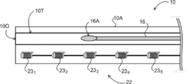
- FIG. 2 is a block diagram illustrating an example of a configuration of an image processing unit according to the embodiment. It is a sectional view showing an example of a state of a treatment instrument inserted in an endoscope of an embodiment.
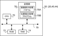
- FIG. 3 is a block diagram illustrating an example of a detection unit, each control unit, and a hardware configuration according to the embodiment.
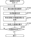
- FIG. 6 is a flowchart illustrating an example of an image display process performed by a detection unit according to the embodiment.
- FIG. 4 is a diagram for describing an example of a shape image generated by a shape detection unit of the detection unit according to the embodiment.
- FIG. 5 is a diagram illustrating an example of a composite image including an endoscope image and a shape image displayed on the display unit according to the embodiment.
- 5 is a flowchart illustrating an example of a position detection process performed by a detection unit according to the embodiment. It is a figure showing an example of a mark showing a position of a tip part of a treatment instrument displayed on a display of an embodiment. It is a figure for explaining the modification in which a detection part of an embodiment is further provided with a magnetization part. It is a figure for explaining the modification in which a detection part of an embodiment is further provided with a magnetic field generating member.
- FIG. 1 is a configuration diagram illustrating an example of a configuration of an endoscope system 1 according to the present embodiment.
- the endoscope system 1 includes an endoscope 10, an endoscope inspection device 12, a position detection device 14, and a treatment tool 16 that capture an image of the body of the subject W (hereinafter, referred to as an “endoscope image”).
- an endoscope image an image of the body of the subject W
- the endoscope 10 includes an insertion section 10A and an operation section 10B.
- the examiner operates the operation section 10B to insert the insertion section 10A into the subject W, and An endoscopic image of the inside of the body of the subject.
- the endoscope inspection device 12 connected to the endoscope 10 by the cable 11 includes a video processor 34, an overall control unit 40, a transmission unit 41, a detection unit 50, and a display unit 52 such as a liquid crystal display.
- the video processor 34 controls the endoscope 10 to capture an endoscopic image.
- the overall control unit 40 controls the entire endoscope system 1.
- the detection unit 50 detects the shape of the insertion section 10A of the endoscope 10 and detects the position of the treatment tool 16.
- the detection unit 50 of the present embodiment is an example of the detection device of the present disclosure.
- the position detection device 14 includes a transmission unit 41 provided in the endoscope inspection device 12 and a reception unit 21 (see FIG. 2) provided inside the endoscope 10.
- the position of the insertion section 10A is detected by receiving the generated magnetic field by the reception section 21.
- the video processor 34, the overall control unit 40, the transmission unit 41, the detection unit 50, and the display unit 52 are illustrated in the same housing in FIG. 1, these units are provided in different housings, for example. A configuration may be used, or one or more may be provided in another housing.
- the treatment tool 16 is inserted into the subject W along the insertion section 10A of the endoscope 10 to inspect or treat the inside of the subject W.
- the insertion portion 10A of the endoscope 10 has a distal end (hereinafter, simply referred to as “the distal end of the insertion portion 10A”) inserted into the subject W of the insertion portion 10A. ) Has an opening 100 and a treatment instrument tube 10T into which the treatment instrument 16 is inserted.
- the examiner inserts the insertion section 10A of the endoscope 10 into the subject W.
- the treatment instrument 16 is inserted into the treatment instrument tube 10T from an opening (not shown) provided on the operation section 10B side, whereby the treatment instrument 16 is inserted into the subject W. Then, the distal end portion 16A of the treatment tool 16 projects from the opening 100 toward the body of the subject W, and the treatment tool 16 performs an inspection or treatment on the subject W. Examples of the treatment tool 16 include an electric scalpel, biopsy forceps, and a hemostatic clip.
- FIG. 2 is a block diagram illustrating an example of a configuration of the endoscope system 1 according to the present embodiment.
- the endoscope 10 includes an image sensor 30 including an image sensor such as a charge coupled device (CCD) image sensor and a complementary metal-oxide-semiconductor (CMOS) image sensor.
- the endoscope 10 transmits light emitted from the light source 36 under the control of the video processor 34 through a transmission path (not shown), and emits the light from an emission unit (not shown) provided at the distal end of the insertion unit 10A.
- the inside of the subject W is illuminated by the light thus emitted.
- the reflected light from the subject W due to the illumination light forms an image on the image sensor 30 by an objective lens (not shown), and an image signal corresponding to the formed endoscope image as an optical image is transmitted via the cable 11. It is output to the video processor 34 of the endoscope inspection apparatus 12.
- a predetermined image processing is performed on the input image signal by the video processor 34, and the image data of the endoscope image obtained by the image processing is output to the detection unit 50.
- the transmission unit 41 included in the endoscope inspection device 12 of the position detection device 14 includes a transmission control unit 42 and a transmission coil unit 48.
- the transmission coil unit 48 includes a plurality (12 in the present embodiment) of transmission coils 49, specifically, transmission coils 49 1x , 49 1Y , 49 1Z , 49 2x , and 49 2Y. , 49 2Z , 493x , 493Y , 493Z , 494x , 494Y , and 494Z .
- the transmission coil 49 may be collectively simply referred to as "transmission coil 49", to distinguish individually, codes representing individual after "transmission coil 49 '(1X ⁇ ⁇ ⁇ 4Z ).
- the transmission coil 49 of the present embodiment is an example of the other plurality of elements of the present disclosure.
- the transmission coil 49 of the present embodiment has a set of three transmission coils 49 whose axes are oriented in the respective directions of the X axis, the Y axis, and the Z axis. , Four transmission coil groups.
- the transmission coil unit 48 includes a set of a transmission coil 49 1X oriented in the X-axis direction, a transmission coil 49 1Y oriented in the Y-axis direction, and a transmission coil 49 1Z oriented in the Z-axis direction; A transmission coil 49 2X oriented in the direction, a transmission coil 49 2Y oriented in the Y-axis direction, and a transmission coil 49 2Z oriented in the Z-axis direction.
- the transmission coil unit 48 includes a set of a transmission coil 49 3X oriented in the X-axis direction, a transmission coil 49 3Y oriented in the Y-axis direction, and a transmission coil 49 3Z oriented in the Z-axis direction.
- the transmission coil unit 48 of the present embodiment is equivalent to a state in which four triaxial coils are provided as the transmission coil 49.
- the transmission control unit 42 also includes a transmission circuit 46 connected to the transmission control unit 44 and the transmission coil 49, specifically, the transmission circuits 46 1x , 46 1Y , 46 1Z , 46 2x , 46 2Y , 46 2Z , 46 3x , 46 3Y , 46 3Z , 46 4x , 46 4Y , and 46 4Z .
- the transmission circuit 46 is simply referred to as the “transmission circuit 46” as in the case of the transmission coil 49 when collectively referred to. Symbols ( 1X ... 4Z ) are given.
- the transmission circuit 46 generates a drive signal for driving the transmission coil 49 under the control of the transmission control unit 44 and outputs the drive signal to the transmission coil 49 connected to each.
- Each transmission coil 49 emits an electromagnetic wave accompanied by a magnetic field to the surroundings when a drive signal is applied.
- the transmission control unit 44 of the present embodiment causes each transmission circuit 46 to generate a drive signal at predetermined time intervals, for example, at intervals of several tens of milliseconds, and drives each transmission coil 49 sequentially.
- the reception unit 21 provided inside the endoscope 10 includes a reception control unit 20, a reception coil unit 22, and a reception circuit 24 (24 1 to 24 16). ), An ADC (Analog-to-Digital Converter) 26 (26 1 to 26 16 ), and an I / F (Interface) 29.
- the reception control unit 20 controls the entire reception unit 21 and controls the driving of the reception coil unit 22.
- the receiving coil unit 22 includes 16 receiving coils 23 (six in FIG. 3), specifically, receiving coils 23 1 to 23 16 as an example.
- each of the reception coil 23, the reception circuit 24, and the ADC 26 is simply referred to as “the reception coil 23”, “the reception circuit 24”, and “the ADC 26”.
- reference numerals ( 1 ... 16 ) representing the individual units are given after the "receiving coil 23", the "receiving circuit 24", and the "ADC 26".
- the receiving coil 23 of the present embodiment is an example of one of the plurality of elements of the present disclosure.
- Each receiving coil 23 of the receiving coil unit 22 is disposed in the insertion section 10A of the endoscope 10 along the direction in which the receiving coil 23 is inserted into the subject W, as shown in FIG.
- the receiving coil 23 detects a magnetic field generated by each transmitting coil 49 of the transmitting coil unit 48.
- Each receiving coil 23 is connected to a receiving circuit 24, and outputs a detection signal corresponding to the detected magnetic field to the receiving circuit 24.
- the receiving circuit 24 includes an LPF (Low Pass Filter), an amplifier (both not shown), and the like.
- the LPF removes disturbance noise, and outputs a detection signal amplified by the amplifier to the ADC 26.
- the ADC 26 converts the input analog detection signal into a digital detection signal and outputs the digital detection signal to the reception control unit 20.
- the reception control unit 20 transmits the detection signal input from each ADC 26 to the endoscope inspection device 12 via the I / F 29.
- the detection signal input to the endoscope inspection device 12 is input to the detection unit 50 via the I / F 53.
- the detecting unit 50 detects the position of each receiving coil 23 based on the input detection signal. That is, the detection unit 50 of the present embodiment detects the magnetic field generated by each transmission coil 49 with the reception coil 23, and based on the detection signal output from the reception coil 23, the position and direction (direction) of each reception coil 23. ) Is detected.
- the method by which the detection unit 50 detects the position of the receiving coil 23 based on the detection signal is not particularly limited, and for example, a technique described in Japanese Patent No. 3432825 can be applied. According to the technology described in Japanese Patent No. 3432825, the distance between a specific transmission coil 49 and the reception coil 23 is determined from the measured value of the magnetic field generated by each transmission coil 49 and the estimated value of the direction of the reception coil 23. Calculate the estimate.
- the estimated value of the position of the receiving coil 23 is calculated from the estimated value of the distance from each transmitting coil 49 to the receiving coil 23 and the known position of the transmitting coil 49.
- a new estimated value of the direction of the receiving coil 23 is calculated from the estimated position of the receiving coil 23 and the measured value of the magnetic field of the receiving coil 23. Then, by using the new estimated value of the direction of the receiving coil 23 to repeat the calculation of the estimated value of the distance from the transmitting coil 49 to the receiving coil 23 and the calculation of the estimated value of the position of the receiving coil 23, The position and direction of the receiving coil 23 are derived.
- the detection unit 50 of the present embodiment detects the shape of the insertion unit 10A of the endoscope 10 based on the detected position and direction of each reception coil 23.
- FIG. 4 shows a functional block diagram of an example of the detection unit 50 of the present embodiment.
- the detection unit 50 of the present embodiment includes an acquisition unit 60, a shape detection unit 62, an image generation unit 64, a position detection unit 66, a display control unit 68, and a notification unit 67.
- the detection signal is input to the acquisition unit 60 from the position detection device 14, specifically, from the reception control unit 20 of the endoscope 10 via the I / F 29 and the I / F 53.
- the acquisition unit 60 outputs the input detection signal to the shape detection unit 62 and the position detection unit 66.
- the shape detector 62 detects the position and the direction of each receiving coil 23 based on the input detection signal.
- the shape detection unit 62 detects the shape of the insertion unit 10A based on the detected position and direction of the reception coil 23, and generates information representing the detected shape and the position and direction of each reception coil 23 as an image. Output to the unit 64.
- the image generation unit 64 is a shape image that represents the shape of the insertion unit 10A from a predetermined viewpoint direction (details will be described later) based on information representing the shape of the insertion unit 10A and the position and direction of each reception coil 23. (Details will be described later). Further, the image data of the endoscope image is input from the video processor 34 to the image generation unit 64. The image generation unit 64 generates a composite image by combining the image data of the generated shape image with the image data of the endoscope image, and outputs the generated image data of the composite image to the display control unit 68.
- the position detection unit 66 analyzes the detection signal of each reception coil 23 based on the input detection signal. Further, the position detection unit 66 detects the position of the treatment tool 16 based on a change in the magnetic field of each reception coil 23 obtained by analyzing the detection signal.
- the position detection unit 66 of the present embodiment detects the position of the treatment tool 16 in the treatment tool tube 10T (see FIG. 5) based on the detection signal.
- each receiving coil 23 of the receiving coil unit 22 is provided along the treatment instrument tube 10T.
- the arrangement of the receiver coils 23, the insertion portion 10A and the tip receiving coil 23 1 is provided in the toward the rear end of the insertion portion 10A, the receiving coil 23 2 , it is provided along the treatment instrument tube 10T in the order of 23 3,.
- the treatment tool 16 of the present embodiment is configured to include a metal component. Therefore, when the distal end portion 16A of the treatment tool 16 approaches the vicinity of each receiving coil 23, the magnetic field generated by each transmitting coil 49 and received by each receiving coil 23 is disturbed.
- the disturbance of the magnetic field affects a detection signal output from the receiving coil 23 to which the distal end 16A of the treatment tool 16 approaches. Specifically, the amplitude, phase, and frequency of the detection signal change due to the disturbance of the magnetic field.
- the position detecting unit 66 of the present embodiment specifies the receiving coil 23 in which the distal end 16A of the treatment instrument 16 is located in the vicinity based on changes in the amplitude, phase, and frequency of the detection signal of each receiving coil 23.
- the position of the treatment tool 16 is detected, and information representing the detection result is output to the display control unit 68.
- the position of the treatment tool 16 may be detected based on, for example, at least one change in the amplitude, phase, and frequency of the detection signal.
- the position detection unit 66 of the present embodiment when the distal end portion 16A of the treatment tool 16 is located within a predetermined range as the vicinity of the distal end of the insertion portion 10A of the endoscope 10, notifies that fact.
- the information indicating that the distal end 16A of the treatment tool 16 is located near the opening 100 is output to the notifying unit 67.
- an example of a position within a predetermined range as the vicinity of the distal end of the insertion portion 10A is set to a position near the receiving coil 23 1.
- the position detector 66 of the present embodiment when the distal end portion 16A of the treatment tool 16 to the position of the receiving coil 23 1 is detected to be located, the position of the distal end portion 16A of the treatment instrument 16, Assuming that the position is the position of the distal end (opening 100) of the insertion section 10A of the endoscope 10, information indicating that is output to the notifying section 67.
- the position detecting section 66 may detect the position of the treatment tool 16 with reference to the position of the insertion section 10A of the endoscope 10, more specifically, the position of each receiving coil 23. In other words, the position detection unit 66 may detect the position of the treatment tool 16 (tip 16A) in the insertion section 10A. In this case, for example, as described above, the position detection unit 66 may specify which of the plurality of reception coils 23 the reception coil 23 located near the distal end portion 16A of the treatment tool 16 is. . Further, the position detection unit 66 may detect the position of the treatment tool 16 based on the subject W. In other words, the position detection unit 66 may detect the position of the treatment tool 16 (tip 16A) in the subject W.
- the position detection unit 66 determines the shape of the insertion unit 10A calculated by the shape detection unit 62 and each reception coil 23 as the insertion amount of the insertion unit 10A into the subject W as a predetermined insertion amount.
- the position of the treatment tool 16 (tip 16A) in the subject W (the position of the treatment tool with reference to the subject) based on the position of the treatment tool 16 (tip 16A) in the insertion portion 10A detected by use. May be derived.
- the position detection unit 66 detects the insertion amount of the insertion unit 10A into the subject W by detecting the insertion amount, the shape of the insertion unit 10A calculated by the shape detection unit 62, and the detection using each reception coil 23.
- the position of the treatment tool 16 (tip 16A) in the subject W may be derived based on the position of the treatment tool 16 (tip 16A) in the inserted portion 10A.
- the amount of insertion of the insertion portion 10A into the subject W can be detected by a known method, but can be detected by, for example, installing a sensor such as a luminance sensor along the insertion portion 10A.
- the reference position of the subject can be a specific site in the subject specified by the user. In this case, the position detection unit 66 calculates the position of the treatment tool with respect to the specific site in the subject specified by the user. Good.
- the notification unit 67 notifies the inspector of information indicating that the distal end 16A of the treatment instrument 16 has approached the distal end (the opening 100) of the insertion unit 10A of the endoscope 10.
- the method of notifying the information by the notifying unit 67 is not particularly limited.
- the endoscope inspection device 12 includes a speaker or the like, the information or the alarm may be notified by outputting a sound. Further, for example, the notification may be performed by visually displaying information and an alarm on a display device such as the display unit 52.
- the notification unit 67 determines whether the treatment tool is a predetermined part of the subject based on the position of the treatment tool 16 (tip 16A) in the subject W (the position of the treatment tool with respect to the subject). May be notified when approaching.
- the display control unit 68 controls the display unit 52 to display a composite image represented by the image data of the composite image output from the image generation unit 64.
- the display control unit 68 displays information indicating the position of the distal end 16A of the treatment instrument 16 based on the information output from the position detection unit 66 and indicating the position of the distal end 16A of the treatment instrument 16.
- the control to display on the unit 52 is performed.
- the detection unit 50 of the present embodiment is realized by a microcomputer or the like including the hardware shown in FIG.
- the detection unit 50 includes a CPU (Central Processing Unit) 70, a ROM (Read Only Memory) 72, a RAM (Random Access Memory) 74, a HDD (Hard Disk Drive), and an SSD (Solid State Drive).
- a nonvolatile storage unit 76 such as a flash memory.
- the CPU 70, the ROM 72, the RAM 74, and the storage unit 76 are connected to a bus 79 so that they can communicate with each other.
- the storage unit 76 stores an image display processing program 78A for executing image display processing, which will be described in detail later, and a position detection processing program 78B for executing position detection processing.
- the CPU 70 reads out each of the image display processing program 78A and the position detection processing program 78B from the storage unit 76, expands the read out image in the RAM 74, and executes each of the expanded image display processing program 78A and position detection processing program 78B.
- the CPU 70 executes each of the image display processing program 78A and the position detection processing program 78B, the acquisition unit 60, the shape detection unit 62, the image generation unit 64, the position detection unit 66, the display control unit 68, and the notification unit 67 Function as each of
- the reception control unit 20, the overall control unit 40, and the transmission control unit 44 are also realized by the same hardware as the detection unit 50 (see FIG. 6).
- FIG. 7 is a flowchart illustrating an example of the flow of an image display process performed by the CPU 70 of the detection unit 50.
- the CPU 70 executes the image display processing program 78A to execute the image display processing shown in FIG. Is executed.
- the shape detection unit 62 analyzes the shape of the insertion unit 10A.
- the shape detection unit 62 detects the position and the direction of each reception coil 23 based on the detection signal input from the acquisition unit 60. Further, the shape of the insertion section 10A is analyzed based on the detected position and direction of the reception coil 23.
- the shape detection unit 62 outputs information indicating the shape of the insertion unit 10A and the position and direction of each reception coil 23 to the image generation unit 64.
- the image generation unit 64 generates a shape image indicating the shape of the insertion unit 10A from a predetermined viewpoint direction based on the information indicating the shape of the insertion unit 10A and the position and direction of each receiving coil 23.
- the predetermined viewpoint direction in the present embodiment is a direction predetermined as a viewpoint direction for grasping the entire shape of the insertion section 10A.
- a specific example of such a predetermined viewpoint direction is the Z-axis direction in the transmission coil unit 48 shown in FIG. 3.
- the shape image 90 representing the shape of the insertion section 10A from a predetermined viewpoint direction is a two-dimensional image represented by the Y axis and the Z axis, as shown in FIG.
- the image generation unit 64 generates a composite image obtained by combining the shape image 90 and the endoscope image, and displays the image data of the composite image including the shape image 90 and the endoscope image on the display control unit. 68.
- the display controller 68 causes the display 52 to display the composite image.
- FIG. 9 shows an example of the composite image 100 displayed on the display unit 52.
- the composite image 100 shown in FIG. 9 includes a shape image 90 and an endoscope image 94.
- an image obtained by synthesizing the shape image 90 and the endoscope image 94 in a state where they are arranged side by side is used as the synthesized image 100. It is not limited to.
- the degree of superposition of the shape image 90 and the endoscope image 94 in the composite image 100, the size of each image, and the like need only be such that an image desired by the inspector is appropriately displayed in the endoscopic examination.
- the synthesized image 100 may be an image synthesized in a state where at least a part of the shape image 90 and the endoscope image 94 are superimposed.
- the combined image 100 may be configured to control the degree of superposition of the shape image 90 and the endoscope image 94 and the size of each image according to the size of the display unit 52 and the like.
- step S108 the display control unit 68 determines whether or not to end the endoscopy.
- the determination in step S108 is negative until an instruction to end the endoscopic inspection is received from the examiner, and Returning to S100, each processing of steps S102 to S106 is repeated.
- the determination in step S108 is affirmative, and the image display processing ends.
- FIG. 10 is a flowchart illustrating an example of the flow of a position detection process performed by the CPU 70 of the detection unit 50.
- the CPU 70 executes the position detection processing program 78B to execute the position detection processing illustrated in FIG. Is executed.
- Step position detecting unit 66 in S150 analyzes the detection signal of the receiving coil 23 1 provided on the distal end of the insertion portion 10A of the endoscope 10.
- the position detecting unit 66 analyzes the inputted from the acquisition unit 60, the receiving coil 23 1 of the detection signal amplitude, phase, and each of the change in frequency.
- the position detection unit 66 determines whether or not the magnetic field is disordered based on the analysis result in step S150.
- changes in the amplitude, phase, and frequency of the detection signal corresponding to the disturbance of the magnetic field generated by the distal end portion 16A of the treatment tool 16 are analyzed in advance, and the amount of change that is considered to be caused by the disturbance of the magnetic field Is obtained in advance.
- the position detection unit 66 determines that the magnetic field disturbance has occurred when the change amount of each of the amplitude, phase, and frequency of the detection signal exceeds the obtained threshold.
- the change amount of each of the amplitude, phase, and frequency of the detection signal is equal to or smaller than the obtained threshold value, it is determined that the magnetic field is not disturbed.
- the process moves to S154.
- Position detecting unit 66 in step S154 the receiving coil 23 corresponding to the detection signal, determines whether the receiver coil 23 16 provided on the rearmost end of the insertion portion 10A of the endoscope 10.
- the determination in step S154 is affirmative, the process returns to step S150, and repeats the processes of steps S150 and S152.
- the occurrence of the disturbance of the magnetic field is not detected from any of the detection signals of the receiving coils 23.
- the treatment tool 16 is still inserted into the treatment tool tube 10T of the endoscope 10. If not.
- step S154 the determination in step S154 becomes negative, the process proceeds to step S156.
- step S156 the position detection unit 66 analyzes the detection signals of the reception coils 23 arranged next to the reception coil 23 that analyzed the detection signals immediately before in the same manner as in step S150, and then returns to step S152.
- the position detector 66 the following of the analysis of the detection signal of the receiving coil 23 1 analyzes the detection signal of the receiving coil 23 2.
- step S152 the determination in step S152 is affirmative, and the process proceeds to step S158.
- step S158 the position detection unit 66 specifies the position of the distal end 16A of the treatment instrument 16, and outputs information representing the position of the distal end 16A to the display control unit 68. Specifically, the position detection unit 66 specifies the position of the reception coil 23 corresponding to the detection signal that has determined that the magnetic field is disturbed, as the position of the distal end 16A of the treatment tool 16. For example, in the example shown in FIG. 5, the distal end portion 16A of the treatment instrument 16 is positioned in the vicinity of the receiver coil 23 3.
- Position detecting unit 66 analyzes the detection signal of the receiving coil 23 1 sequentially receives based on the detection signal of the coil 23 3, for determining the magnetic field disturbance occurs, the receive coil 23 3 positions the treatment instrument 16 Is specified as the position of the tip 16A. Then, the position detection unit 66 acquires the position of the receiver coil 23 3 from the shape detection unit 62, and outputs to the display control unit 68.
- the display controller 68 causes the display 52 to display information indicating the position of the distal end 16A of the treatment instrument 16.
- the mark indicating the position of the distal end portion 16A is superimposed on the shape image 90 displayed on the display unit 52 by the above-described image display processing, so that the distal end portion 16A of the treatment tool 16 is displayed. Is displayed on the display unit 52.
- FIG. 11 shows an example of the composite image 100 displayed on the display unit 52 and the mark 96 indicating the position of the distal end 16 ⁇ / b> A of the treatment tool 16.
- a mark 96 is superimposed on the shape image 90 of the composite image 100 shown in FIG.
- step S162 the position detecting section 66 determines whether or not the position of the distal end portion 16A of the treatment instrument 16 specified in step S158 is the position of the distal end of the insertion section 10A of the endoscope 10. If it is the position of the distal end of the insertion section 10A of the endoscope 10, the determination in step S162 is affirmative, and the process proceeds to step S164.
- step S164 the notification unit 67 causes the display unit 52 to display information indicating that the distal end 16A of the treatment instrument 16 has approached the distal end (opening 100) of the insertion unit 10A of the endoscope 10.
- the mark 96 indicating the position of the distal end portion 16A of the treatment instrument 16 displayed on the display unit 52 is flickered, so that the distal end portion 16A is positioned at the distal end of the insertion portion 10A of the endoscope 10. It informs the inspector that it has approached the (opening 100).
- the process returns to step S150, and the processes in steps S152 to S162 are repeated.
- step S162 determines whether to end the endoscopic examination.
- step S108 see FIG. 7 of the image display process described above
- the operation in step S166 is performed until an examiner receives an instruction to end the endoscopic examination by operating an unillustrated operation button or the like. Is negative, the process returns to step S150, and repeats the processes of steps S152 to S164.
- step S166 is affirmative, and the position detection indicating process ends.
- the detection unit 50 of the present embodiment includes the acquisition unit 60 and the position detection unit 66.
- the acquisition unit 60 includes a receiving coil 23, which is one of a plurality of magnetic field generating elements and a magnetic field detecting element, provided along the insertion unit 10A of the endoscope 10 inserted into the subject W, and the subject W , A detection signal representing a magnetic field detected by the transmission coil 49, which is the other plurality of elements provided outside.
- the position detection unit 66 examines the inside of the subject W to be inserted into the subject W along the insertion unit 10A of the endoscope 10 based on the change in the magnetic field according to the detection signal acquired by the acquisition unit 60. The position of the treatment tool 16 for treatment is detected.
- each receiving coil 23 included in the receiving coil unit 22 of the receiving unit 21 of the position detecting device 14 is provided along the insertion section 10A of the endoscope 10.
- the position detection unit 66 of the detection unit 50 detects the position of the distal end 16A of the treatment tool 16 based on a change in the magnetic field according to the detection signal of each reception coil 23.
- the position of the distal end portion 16A of the treatment tool 16 is determined based on the detection signals of the plurality of reception coils 23 provided along the insertion portion 10A of the endoscope 10. Is detected. Therefore, according to the detection section 50 of the present embodiment, the position of the treatment tool 16 inserted into the subject W along the insertion section 10A of the endoscope 10 can be grasped more accurately in the subject W. it can.
- the detection unit 50 of the present embodiment uses the detection signal of the receiving coil 23 provided in the position detection device 14 to detect the position of the treatment tool 16. Therefore, according to the endoscope system 1 of the present embodiment, it is not necessary to newly provide an element that generates a detection signal for detecting the position of the treatment tool 16. Since it is not necessary to provide a new element in the insertion section 10A of the endoscope 10, the insertion section 10A of the endoscope 10 can be reduced in size as compared with a case where a new element is provided, and The burden can be reduced.
- the detection of the shape of the insertion section 10A of the endoscope 10 by the shape detection section 62 and the generation and display of the shape image 90 are not essential, and are performed by the shape detection section 62 in response to, for example, an examiner's instruction. It is good also as a form to do.
- the detection signals are analyzed in order from the reception coil 23 provided at the distal end of the insertion section 10A of the endoscope 10, and it is determined that the magnetic field is disordered. Thereafter, the detection signal of the reception coil 23 provided on the operation unit 10B side is not analyzed.
- the position detection processing is not limited to this embodiment.
- the detection signals may be analyzed in order from the reception coil 23 provided at the rear end (the side closer to the operation unit 10B) of the insertion section 10A of the endoscope 10. Further, when the treatment instrument 16 is inserted into the treatment instrument tube 10T of the endoscope 10, the magnetic field may be disturbed even at a position other than the distal end portion 16A of the treatment instrument 16.
- the magnetic field may be disturbed other than at the distal end 16A of the treatment tool 16, and the detection signals of all the receiving coils 23 corresponding to the region where the treatment tool 16 is inserted may change.
- the position detection unit 66 analyzes the detection signals of all the reception coils 23 and specifies the position of the reception coil 23 having the largest change in the detection signal as the position of the distal end portion 16A of the treatment instrument 16. May be.
- the position detecting section 66 may further include a magnetizing section 69 as in the example shown in FIG.
- the distal end 16A of the treatment instrument 16 is magnetized by the magnetizing section 69, and the distal end 16A is magnetized. Disturbance can be increased. In this case, since the amount of change in the detection signal of the receiving coil 23 used for detecting the position of the treatment tool 16 can be increased, the detection accuracy can be improved.
- the magnetizing unit 69 it is preferable to use a work tool such as a driver, or a hand-held magnetizing device used for magnetizing a blade or the like.
- the position detecting section 66 may further include a magnetism generating member 17 attached to the distal end portion 16A of the treatment instrument 16, as in the example shown in FIG.
- a magnetism generating member 17 attached to the distal end portion 16A of the treatment instrument 16, as in the example shown in FIG.
- the distal end portion 16A of the treatment tool 16 preferably has an object that tends to be magnetized, and particularly preferably has a ferromagnetic material.
- the material of the distal end portion 16A may be a ferromagnetic material. Examples of this type of ferromagnetic material include ferrite stainless steel and martensite stainless steel. Even when the distal end portion 16A of the treatment instrument 16 has a ferromagnetic material, it is preferable that the distal end portion 16A be magnetized by the magnetizing section 69 or the like before being inserted into the subject W, as in the above-described example.
- the position detecting device 14 the transmitting unit 41 including the transmitting coil unit 48 that generates a magnetic field in the endoscope inspection device 12, and the receiving coil unit 22 that detects the magnetic field in the endoscope 10 are provided.
- the receiving section 21 including the receiving section 21 is arranged, the position detecting device 14 is not limited to the present embodiment.
- a magnetic field generating element that generates a magnetic field other than the transmission coil unit 48 (transmission coil 49) such as a spin torque oscillation element may be used.
- a magnetic field detecting element for detecting a magnetic field other than the receiving coil unit 22 (receiving coil 23) such as a Hall element or an MR (Magneto Resistive) element may be used.
- the position detection device 14 may be configured such that the reception unit 21 is disposed in the endoscope inspection device 12 and the transmission unit 41 is disposed in the endoscope 10.
- the detection unit 50 has the functions of the acquisition unit 60, the shape detection unit 62, the image generation unit 64, the position detection unit 66, the display control unit 68, and the notification unit 67 has been described. Some of these functions may be provided in another device or a plurality of devices. For example, one of the shape detection unit 62 and the position detection unit 66 may be provided in a device external to the detection unit 50.
- the form in which the shape detection unit 62 generates the combined image 100 in which the shape image 90 and the endoscope image 94 are combined has been described.
- the endoscope image 94 may be displayed on the display unit 52 as a separate image without being combined. Further, each of the endoscope image 94 and the shape image 90 may be displayed on a separate display device.
- a processing unit that executes various types of processing, such as an acquisition unit 60, a shape detection unit 62, an image generation unit 64, a position detection unit 66, a display control unit 68, and a notification unit 67, for example
- the following various processors can be used.
- the CPU which is a general-purpose processor that executes software (programs) and functions as various processing units
- the above-described various processors include a circuit after manufacturing an FPGA (Field Programmable Gate Array) or the like.
- Dedicated electricity which is a processor having a circuit configuration specifically designed to execute a specific process such as a programmable logic device (PLD) or an ASIC (Application Specific Integrated Circuit), which is a processor whose configuration can be changed. Circuit etc. are included.
- PLD programmable logic device
- ASIC Application Specific Integrated Circuit
- One processing unit may be configured by one of these various processors, or a combination of two or more processors of the same type or different types (for example, a combination of a plurality of FPGAs or a combination of a CPU and an FPGA). Combination). Further, a plurality of processing units may be configured by one processor.
- one processor is configured by a combination of one or more CPUs and software. There is a form in which the processor functions as a plurality of processing units.
- SoC System On Chip
- the various processing units are configured using one or more of the above various processors as a hardware structure.
- circuitry in which circuit elements such as semiconductor elements are combined can be used.
- each of the image display processing program 78A and the position detection processing program 78B is a recording medium such as a CD-ROM (Compact Disk Read Only Memory), a DVD-ROM (Digital Versatile Disk Read Only Memory), and a USB (Universal Serial Bus) memory. May be provided in the form recorded in the. Further, each of the image display processing program 78A and the position detection processing program 78B may be configured to be downloaded from an external device via a network.
Landscapes
- Health & Medical Sciences (AREA)
- Life Sciences & Earth Sciences (AREA)
- Surgery (AREA)
- Nuclear Medicine, Radiotherapy & Molecular Imaging (AREA)
- Biomedical Technology (AREA)
- Optics & Photonics (AREA)
- Pathology (AREA)
- Radiology & Medical Imaging (AREA)
- Biophysics (AREA)
- Engineering & Computer Science (AREA)
- Physics & Mathematics (AREA)
- Heart & Thoracic Surgery (AREA)
- Medical Informatics (AREA)
- Molecular Biology (AREA)
- Animal Behavior & Ethology (AREA)
- General Health & Medical Sciences (AREA)
- Public Health (AREA)
- Veterinary Medicine (AREA)
- Endoscopes (AREA)
Abstract
内視鏡の挿入部に沿って被検体に挿入される処置具の被検体内における位置を、より精確に把握することができる、検出装置、内視鏡システム、検出方法、及び検出プログラムを提供する。検出部50は、内視鏡10における被検体Wに挿入する挿入部10Aに沿って設けられた、磁界発生素子、及び磁界検出素子の一方の複数の素子である受信コイル23、及び被検体Wの外部に設けられた他方の複数の素子である送信コイル49によって検出された磁界を表す検出信号を取得する取得部60と、取得部60が取得した検出信号に応じた磁界の変化に基づいて、内視鏡10の挿入部10Aに沿って被検体Wに挿入する、被検体Wの体内を検査または処置するための処置具16の位置を検出する位置検出部66と、を備える。
Description
本開示は、検出装置、内視鏡システム、検出方法、及び検出プログラムに関する。
従来、被検体の体内を処置対象として、被検体に挿入した内視鏡により観察し、被検体に挿入した処置具により処置対象の検査または処置を行う内視鏡システムが知られている。このシステムは、処置具を検査または処置を行う位置として適切な位置に挿入する必要があり、処置具の位置を把握するための技術が知られている。例えば、特許文献1には、処置具の挿入量を検出する技術が記載されている。また例えば、特許文献2には、処置具の先端に永久磁石を設け、処置具を挿入する内視鏡の挿入部における操作部側の特定の位置にホール素子を位置センサとして設け、ホール素子が検出した磁界の変化に基づいて、処置具の先端の位置を検出する技術が記載されている。
しかしながら、上記特許文献1に記載の技術では、処置具の挿入量はわかるものの、被検体の体内における処置具の位置が把握し難い場合があった。また、特許文献2に記載の技術では、特定の位置に処置具の先端部が位置するか否かは把握できるが、特定の位置以外に処置具の先端部が位置する場合、被検体内における処置具の位置が把握し難い場合があった。
本開示は、以上の事情を鑑みて成されたものであり、内視鏡の挿入部に沿って被検体に挿入される処置具の被検体内における位置を、より精確に把握することができる、検出装置、内視鏡システム、検出方法、及び検出プログラムを提供することを目的とする。
上記目的を達成するために、本開示の第1の態様の検出装置は、複数の磁界発生素子及び複数の磁界検出素子のうち、内視鏡における被検体に挿入する挿入部に沿って設けられた、一方の複数の素子と、被検体の外部に設けられた他方の複数の素子とによって検出される磁界を表す検出信号を取得する取得部と、取得部が取得した検出信号に応じた磁界の変化に基づいて、内視鏡の挿入部に沿って被検体に挿入する、被検体の体内を検査または処置するための処置具の位置を検出する位置検出部と、を備える。
本開示の第2の態様の検出装置は、第1の態様の検出装置において、位置検出部は、内視鏡の挿入部を基準とした処置具の位置を検出する。
本開示の第3の態様の検出装置は、第1の態様の検出装置において、位置検出部は、被検体を基準とした処置具の位置を検出する。
本開示の第4の態様の検出装置は、第1の態様から第3の態様のいずれか1態様の検出装置において、取得部が取得した検出信号に基づいて導出された一方の複数の素子各々の位置に基づいて、内視鏡の挿入部の形状を検出する形状検出部をさらに備えた。
本開示の第5の態様の検出装置は、第1の態様の検出装置において、取得部が取得した検出信号に基づいて導出された一方の複数の素子各々の位置に基づいて、前記内視鏡の前記挿入部の形状を検出する形状検出部をさらに備え、位置検出部は、形状検出部により検出された挿入部の形状及び挿入部における前記処置具の位置に基づいて、前記被検体を基準とした処置具の位置を検出する。
本開示の第6の態様の検出装置は、第4の態様又は第5の態様の検出装置において、位置検出部の検出結果、及び形状検出部の検出結果の少なくとも一方を表示部に表示する制御を行う表示制御部をさらに備えた。
本開示の第7の態様の検出装置は、第1の態様から第6の態様のいずれか1態様の検出装置において、位置検出部の検出結果を表示部に表示する制御を行う表示制御部をさらに備えた。
本開示の第8の態様の検出装置は、第1の態様から第7の態様のいずれか1態様の検出装置において、位置検出部は、処置具の被検体に挿入する側の先端部の位置を検出し、位置検出部が検出した処置具の先端部の位置が、内視鏡の挿入部の先端の近傍として予め定められた範囲内の位置である場合に報知する報知部をさらに備えた。
本開示の第9の態様の検出装置は、第1の態様から第8の態様のいずれか1態様の検出装置において、処置具を被検体に挿入する前に、処置具の被検体に挿入する側の先端部を着磁する着磁部をさらに備えた。
本開示の第10の態様の検出装置は、第1の態様から第8の態様のいずれか1態様の検出装置において、処置具を被検体に挿入する場合に、処置具の被検体に挿入する側の先端部に設けられる、磁気発生部材をさらに備えた。
本開示の第11の態様の内視鏡システムは、内視鏡と、内視鏡の挿入部に沿って被検体に挿入され、被検体の体内を検査または処置するための処置具と、複数の磁界発生素子及び複数の磁界検出素子のうち、内視鏡における被検体に挿入する挿入部に沿って設けられた一方の複数の素子と被検体の外部に設けられた他方の複数の素子と、処置具の位置を検出する第1の態様から第10の態様のいずれか1態様に記載の検出装置と、を備える。
本開示の第12の態様の内視鏡システムは、第11の態様の内視鏡システムにおいて、処置具の被検体に挿入する側の先端部は、強磁性体を有する。
本開示の第13の態様の検出方法は、複数の磁界発生素子及び複数の磁界検出素子のうち、内視鏡における被検体に挿入する挿入部に沿って設けられた、一方の複数の素子と、被検体の外部に設けられた他方の複数の素子とによって検出される磁界を表す検出信号を取得し、取得した検出信号に応じた磁界の変化に基づいて、内視鏡の挿入部に沿って被検体に挿入する、被検体の体内を検査または処置するための処置具の位置を検出する、処理をコンピュータが実行する検出方法である。
本開示の第14の態様の検出プログラムは、複数の磁界発生素子及び複数の磁界検出素子のうち、内視鏡における被検体に挿入する挿入部に沿って設けられた、一方の複数の素子と、被検体の外部に設けられた他方の複数の素子とによって検出される磁界を表す検出信号を取得し、取得した検出信号に応じた磁界の変化に基づいて、内視鏡の挿入部に沿って被検体に挿入する、被検体の体内を検査または処置するための処置具の位置を検出する、処理をコンピュータに実行させるためのものである。
また、本開示の検出装置は、プロセッサを有する検出装置であって、プロセッサが、内視鏡における被検体に挿入する挿入部に沿って設けられた、磁界発生素子、及び磁界検出素子の一方の複数の素子、及び被検体の外部に設けられた他方の複数の素子によって検出された磁界を表す検出信号を取得し、取得した検出信号に応じた磁界の変化に基づいて、内視鏡の挿入部に沿って被検体に挿入する、被検体の体内を検査または処置するための処置具の位置を検出する。
本開示によれば、内視鏡の挿入部に沿って被検体に挿入される処置具の被検体内における位置を、より精確に把握することができる。
以下、図面を参照して、本開示の技術を実施するための形態例を詳細に説明する。
まず、図1を参照して本実施形態の内視鏡システム1の全体の構成について説明する。
図1には、本実施形態の内視鏡システム1の構成の一例を示す構成図が示されている。
内視鏡システム1は、被検体Wの体内の画像(以下、「内視鏡画像」という)を撮像する内視鏡10、内視鏡検査装置12、位置検出装置14、及び処置具16を備えている。
内視鏡10は、挿入部10A及び操作部10Bを備え、内視鏡検査を行う場合、検査者は、操作部10Bを操作して、挿入部10Aを被検体Wに挿入し、被検体Wの体内の内視鏡画像を撮像する。ケーブル11により内視鏡10と接続された内視鏡検査装置12は、ビデオプロセッサ34、全体制御部40、送信部41、検出部50、及び液晶ディスプレイ等の表示部52を備える。ビデオプロセッサ34は、内視鏡10による内視鏡画像の撮像の制御を行う。全体制御部40は、内視鏡システム1の全体を制御する。検出部50は、内視鏡10の挿入部10Aの形状の検出、及び処置具16の位置の検出を行う。本実施形態の検出部50が、本開示の検出装置の一例である。一方、位置検出装置14は、内視鏡検査装置12に備えられた送信部41と、内視鏡10の内部に設けられた受信部21(図2参照)と、を備え、送信部41で発生した磁界を受信部21で受信することにより、挿入部10Aの位置を検出する。なお、図1では、ビデオプロセッサ34、全体制御部40、送信部41、検出部50、及び表示部52を同一の筐体内に図示したが、これら各部は、例えば、各々異なる筐体内に備えられる構成としてもよいし、1つ以上を別の筐体内に備える構成としてもよい。
処置具16は、内視鏡10の挿入部10Aに沿って、被検体Wに挿入され、被検体Wの体内を検査または処置するためのものである。具体的には、一例として図5に示したように、内視鏡10の挿入部10Aには、挿入部10Aの被検体Wに挿入される先端(以下、単に「挿入部10Aの先端」という)に開口部10Oを有し、処置具16が挿入される処置具チューブ10Tが設けられている。被検体Wの体内を検査または処置する場合、検査者により被検体Wに内視鏡10の挿入部10Aが挿入される。その後、操作部10B側に設けられた、図示を省略した開口部から処置具チューブ10Tに処置具16が挿入されることで、処置具16が被検体Wに挿入される。そして、開口部10Oから被検体Wの体内に向けて処置具16の先端部16Aが突出し、処置具16により被検体Wの検査または処置が行われる。処置具16の一例としては、電気メス、生検鉗子、及び止血クリップ等が挙げられる。
次に、図2を参照して、内視鏡10、内視鏡検査装置12、及び位置検出装置14の詳細な構成について説明する。また、図2には、本実施形態の内視鏡システム1の構成の一例を示すブロック図が示されている。
図2に示すように、内視鏡10は、CCD(Charge Coupled Device)イメージセンサ、及びCMOS(Complementary Metal-Oxide-Semiconductor)イメージセンサ等の撮像素子を含む画像センサ30を備えている。内視鏡10は、ビデオプロセッサ34の制御により光源36から出射された光を伝送路(図示省略)によって伝送し、挿入部10Aの先端に設けられた出射部(図示省略)から出射し、出射した光によって被検体Wの体内を照明する。この照明光による被検体Wからの反射光が対物レンズ(図示省略)によって画像センサ30に結像し、結像した光学像である内視鏡画像に応じた画像信号が、ケーブル11を介して内視鏡検査装置12のビデオプロセッサ34に出力される。ビデオプロセッサ34により、入力された画像信号に対して予め定められた画像処理が行われ、この画像処理によって得られた内視鏡画像の画像データは、検出部50に出力される。
図2に示すように、位置検出装置14のうち、内視鏡検査装置12に備えられた送信部41は、送信制御ユニット42及び送信コイルユニット48を備える。送信コイルユニット48は、図3にも示すように、複数(本実施形態では、12個)の送信コイル49、具体的には、送信コイル491x、491Y、491Z、492x、492Y、492Z、493x、493Y、493Z、494x、494Y、及び494Zを備える。なお、本実施形態では、送信コイル49について、総称する場合は、単に「送信コイル49」といい、個々を区別する場合は、「送信コイル49」の後に個々を表す符号(1X・・・4Z)を付す。本実施形態の送信コイル49が、本開示の他方の複数の素子の一例である。
図3に示すように、本実施形態の送信コイル49は軸が、X軸、Y軸、及びZ軸の各々の方向に向いた3つの送信コイル49を1組としており、送信コイルユニット48は、4組の送信コイル群を備える。具体的には、送信コイルユニット48は、X軸方向に向いた送信コイル491X、Y軸方向に向いた送信コイル491Y、及びZ軸方向に向いた送信コイル491Zの組と、X軸方向に向いた送信コイル492X、Y軸方向に向いた送信コイル492Y、及びZ軸方向に向いた送信コイル492Zの組と、を備える。また、送信コイルユニット48は、X軸方向に向いた送信コイル493X、Y軸方向に向いた送信コイル493Y、及びZ軸方向に向いた送信コイル493Zの組と、X軸方向に向いた送信コイル494X、Y軸方向に向いた送信コイル494Y、及びZ軸方向に向いた送信コイル494Zの組と、を備える。このように、本実施形態の送信コイルユニット48は、3軸コイルを4つ、送信コイル49として備えた状態と同等となっている。
また、送信制御ユニット42は、送信制御部44、及び送信コイル49に接続された送信回路46、具体的には、送信回路461x、461Y、461Z、462x、462Y、462Z、463x、463Y、463Z、464x、464Y、及び464Zを備える。なお、本実施形態では、送信回路46についても、送信コイル49と同様に、総称する場合は、単に「送信回路46」といい、個々を区別する場合は、「送信回路46」の後に個々を表す符号(1X・・・4Z)を付す。
送信回路46は、送信制御部44の制御に応じて、送信コイル49を駆動するための駆動信号を生成して、各々接続されている送信コイル49に出力する。各送信コイル49は駆動信号が印加されることで、磁界を伴う電磁波を周囲に放射する。なお、本実施形態の送信制御部44は、予め定められた時間間隔、例えば数十m秒間隔で、各送信回路46に駆動信号を生成させ、各送信コイル49を順次、駆動させる。
一方、図2に示すように、位置検出装置14のうち、内視鏡10の内部に設けられた受信部21は、受信制御部20、受信コイルユニット22、受信回路24(241~2416)、ADC(Analog-to-Digital Converter)26(261~2616)、及びI/F(Interface)29を備える。受信制御部20は、受信部21の全体を制御し、受信コイルユニット22の駆動を制御する。
受信コイルユニット22は、図3にも示すように、一例として16個(図3に図示したものは6個)の受信コイル23、具体的には、受信コイル231~2316を備える。なお、本実施形態では、送信コイル49と同様に、受信コイル23、受信回路24、及びADC26の各々について、総称する場合は、単に「受信コイル23」、「受信回路24」、及び「ADC26」といい、個々を区別する場合は、「受信コイル23」、「受信回路24」、及び「ADC26」の後に個々を表す符号(1・・・16)を付す。本実施形態の受信コイル23が、本開示の一方の複数の素子の一例である。
受信コイルユニット22の各受信コイル23は、図5にも示すように、内視鏡10の挿入部10Aに、被検体Wに挿入される方向に沿って配置されている。受信コイル23は、送信コイルユニット48の各送信コイル49で発生した磁界を検出する。各受信コイル23は、受信回路24に接続されており、検出した磁界に応じた検出信号を受信回路24に出力する。受信回路24は、LPF(Low Pass Filter)及び増幅器(いずれも図示省略)等を含み、LPFによって外乱ノイズが除去され、増幅器により増幅された検出信号をADC26に出力する。ADC26は、入力されたアナログの検出信号をデジタルの検出信号に変換して受信制御部20に出力する。受信制御部20は、各ADC26から入力された検出信号を、I/F29を介して、内視鏡検査装置12へ送信する。
内視鏡検査装置12に入力された検出信号は、I/F53を介して、検出部50に入力される。
検出部50は、入力した検出信号に基づいて、各受信コイル23の位置を検出する。すなわち、本実施形態の検出部50は、各送信コイル49で発生した磁界を受信コイル23で検出し、受信コイル23から出力された検出信号に基づいて、各受信コイル23の位置及び方向(向き)を検出する。検出部50が検出信号に基づいて受信コイル23の位置を検出する方法は、特に限定されず、例えば、特許第3432825号公報に記載されている技術を適用することができる。特許第3432825号公報に記載されている技術では、各送信コイル49によって発生された磁界の測定値、及び受信コイル23の方向の推定値から、特定の送信コイル49から受信コイル23までの距離の推定値を計算する。次に、各送信コイル49から受信コイル23までの距離の推定値と、送信コイル49の既知の位置とから受信コイル23の位置の推定値を計算する。次に、受信コイル23の推定された位置、及び受信コイル23の磁界の測定値から受信コイル23の方向の新しい推定値を計算する。そして、受信コイル23の方向の新しい推定値を用いて、上述した送信コイル49から受信コイル23までの距離の推定値の計算と、受信コイル23の位置の推定値の計算とを繰り返すことにより、受信コイル23の位置及び方向を導出する。
また、本実施形態の検出部50は、検出した各受信コイル23の位置及び方向に基づいて、内視鏡10の挿入部10Aの形状を検出する。図4には、本実施形態の検出部50の一例の機能ブロック図を示す。
図4に示すように、本実施形態の検出部50は、取得部60、形状検出部62、画像生成部64、位置検出部66、表示制御部68、及び報知部67を備える。取得部60には、位置検出装置14から、具体的には、内視鏡10の受信制御部20から、I/F29及びI/F53を介して、上記検出信号が入力される。取得部60は、入力された検出信号を、形状検出部62及び位置検出部66に出力する。
形状検出部62は、入力された検出信号に基づいて、各受信コイル23の位置及び方向を検出する。また、形状検出部62は、検出した受信コイル23の位置及び方向に基づいて、挿入部10Aの形状を検出し、検出した形状を表す情報と、各受信コイル23の位置及び方向とを画像生成部64へ出力する。
画像生成部64は、挿入部10Aの形状を表す情報と、各受信コイル23の位置及び方向とに基づいて、予め定められた視点方向(詳細後述)からの挿入部10Aの形状を表す形状画像(詳細後述)を生成する。また、画像生成部64には、ビデオプロセッサ34から、内視鏡画像の画像データが入力される。画像生成部64は、内視鏡画像の画像データに、生成した形状画像の画像データを合成した合成画像を生成し、生成した合成画像の画像データを表示制御部68に出力する。
一方、位置検出部66は、入力された検出信号に基づいて、各受信コイル23の検出信号を解析する。さらに位置検出部66は、検出信号を解析して得られた、受信コイル23毎の磁界の変化に基づいて、処置具16の位置を検出する。
具体的には、本実施形態の位置検出部66は、検出信号に基づいて、処置具16の、処置具チューブ10T(図5参照)内における位置を検出する。
すなわち、図5に示すように、処置具16は、内視鏡10の挿入部10A内に設けられた処置具チューブ10Tに挿入され、処置具チューブ10T内を、操作部10B側に設けられた開口部(図示省略)と、挿入部10Aの先端に設けられた開口部10Oとの間で移動する。図5に示した一例のように、本実施形態の内視鏡10では、処置具チューブ10Tに沿って、受信コイルユニット22の各受信コイル23が設けられている。具体的には、図5に示すように、各受信コイル23の配置は、挿入部10Aの先端に受信コイル231が設けられており、挿入部10Aの後端に向けて、受信コイル232、233・・・の順に処置具チューブ10Tに沿って設けられている。
本実施形態の処置具16、特に処置具16の先端部16Aは、金属部品を含んで構成されている。そのため、処置具16の先端部16Aが、各受信コイル23の近傍に近付くと、各送信コイル49により発生し、各受信コイル23が受信する磁界が乱れる。磁界の乱れは、処置具16の先端部16Aが近付いた受信コイル23から出力される検出信号に影響を与える。具体的には、磁界が乱れることにより、検出信号の振幅、位相、及び周波数が変化する。
本実施形態の位置検出部66は、各受信コイル23の検出信号の振幅、位相、及び周波数の変化に基づき、処置具16の先端部16Aが近傍に位置する受信コイル23を特定することにより、処置具16の位置を検出し、検出結果を表す情報を表示制御部68に出力する。なお、本実施形態に限定されず、例えば、検出信号の振幅、位相、及び周波数の少なくとも一つの変化に基づいて処置具16の位置を検出してもよい。また、本実施形態の位置検出部66は、処置具16の先端部16Aが、内視鏡10の挿入部10Aの先端の近傍として予め定められた範囲内の位置である場合に、その旨を表す情報、換言すると、処置具16の先端部16Aが開口部10Oの近くに位置していることを表す情報を報知部67に出力する。なお、本実施形態では、挿入部10Aの先端の近傍として予め定められた範囲内の位置の一例を、受信コイル231の近傍の位置としている。換言すると、本実施形態の位置検出部66は、受信コイル231の位置に処置具16の先端部16Aが位置していることを検出した場合に、処置具16の先端部16Aの位置が、内視鏡10の挿入部10Aの先端(開口部10O)部の位置であるとして、その旨を表す情報を報知部67に出力する。
なお、位置検出部66は、内視鏡10の挿入部10Aの位置、より具体的には、各受信コイル23の位置を基準とした、処置具16の位置を検出してもよい。換言すると、位置検出部66は、挿入部10A内における処置具16(先端部16A)の位置を検出してもよい。この場合、例えば、上述したように、位置検出部66は、処置具16の先端部16Aの近傍に位置する受信コイル23が、複数の受信コイル23のうちのいずれであるかを特定すればよい。また、位置検出部66は、被検体Wを基準とした、処置具16の位置を検出してもよい。換言すると、位置検出部66は、被検体W内における処置具16(先端部16A)の位置を検出してもよい。この場合、例えば、位置検出部66は、被検体Wへの挿入部10Aの挿入量を予め定められた挿入量として、形状検出部62で算出した挿入部10Aの形状と、各受信コイル23を用いて検出した挿入部10A内における処置具16(先端部16A)の位置に基づいて、被検体W内における処置具16(先端部16A)の位置(被検体を基準とした処置具の位置)を導出すればよい。また、位置検出部66は、被検体Wへの挿入部10Aの挿入量を検出し検出した挿入量、形状検出部62で算出した挿入部10Aの形状、及び、各受信コイル23を用いて検出した挿入部10A内における処置具16(先端部16A)の位置に基づいて、被検体W内における処置具16(先端部16A)の位置を導出してもよい。被検体Wへの挿入部10Aの挿入量は、公知の方法で検出することが出来るが、例えば挿入部10Aに沿って輝度センサ等のセンサを設置することで検出できる。尚、被検体の基準位置は、ユーザーが指定した被検体における特定部位することが出来、この場合、位置検出部66は、ユーザーが指定した被検体における特定部位に対する処置具の位置を算出すればよい。
報知部67は、処置具16の先端部16Aが、内視鏡10の挿入部10Aの先端(開口部10O)に近付いたことを表す情報を、検査者に報知する。なお、報知部67による情報の報知方法は特に限定されず、例えば、内視鏡検査装置12がスピーカ等を有する場合、音声を出力することにより情報や警報の報知を行ってもよい。また、例えば、表示部52等の表示装置に情報や警報を可視表示することにより報知を行ってもよい。また、報知部67は、被検体W内における処置具16(先端部16A)の位置(被検体を基準とした処置具の位置)に基づいて、処置具が被検体内の予め定められた部位に近づいた場合に報知を行ってもよい。
表示制御部68は、画像生成部64から出力された合成画像の画像データが表す合成画像を表示部52に表示させる制御を行う。また、表示制御部68は、位置検出部66から出力された、検出結果である処置具16の先端部16Aの位置を表す情報に基づき、処置具16の先端部16Aの位置を表す情報を表示部52に表示させる制御を行う。
一例として本実施形態の検出部50は、図6に示したハードウェアを含んで構成されるマイクロコンピュータ等により実現される。図6に示すように、検出部50は、CPU(Central Processing Unit)70、ROM(Read Only Memory)72、RAM(Random Access Memory)74、及びHDD(Hard Disk Drive)、SSD(Solid State Drive)、及びフラッシュメモリ等の不揮発性の記憶部76を備えている。CPU70、ROM72、RAM74、及び記憶部76は、互いに通信が可能にバス79に、接続されている。記憶部76には、共に詳細を後述する画像表示処理を実行するための画像表示処理プログラム78A、及び位置検出処理を実行するための位置検出処理プログラム78Bが記憶されている。CPU70は、記憶部76から画像表示処理プログラム78A及び位置検出処理プログラム78Bの各々を読み出してからRAM74に展開し、展開した画像表示処理プログラム78A及び位置検出処理プログラム78Bの各々を実行する。CPU70が、画像表示処理プログラム78A及び位置検出処理プログラム78Bの各々を実行することで、取得部60、形状検出部62、画像生成部64、位置検出部66、表示制御部68、及び報知部67の各々として機能する。
なお、本実施形態の内視鏡システム1では、受信制御部20、全体制御部40、及び送信制御部44も、検出部50と同様のハードウェア(図6参照)により実現される。
次に、本実施形態の検出部50の作用を説明する。まず、検出部50による、内視鏡10の挿入部10Aの形状の検出について説明する。図7は、検出部50のCPU70によって実行される画像表示処理の流れの一例を示すフローチャートである。一例として、本実施形態の内視鏡システム1では、位置検出装置14から検出信号が入力された場合に、CPU70が、画像表示処理プログラム78Aを実行することにより、図7に示した画像表示処理が実行される。
ステップS100で形状検出部62は、挿入部10Aの形状を解析する。本実施形態では、形状検出部62は、取得部60から入力された検出信号に基づいて、各受信コイル23の位置及び方向を検出する。さらに、検出した受信コイル23の位置及び方向に基づいて、挿入部10Aの形状を解析する。形状検出部62は、挿入部10Aの形状を表す情報と、各受信コイル23の位置及び方向とを画像生成部64へ出力する。
次のステップS102で画像生成部64は、挿入部10Aの形状を表す情報と、各受信コイル23の位置及び方向に基づいて、予め定められた視点方向からの挿入部10Aの形状を表す形状画像を生成する。一例として、本実施形態における予め定められた視点方向とは、挿入部10Aの全体の形状を把握するための視点方向として予め定められた方向である。このような予め定められた視点方向の具体例としては、図3に示した送信コイルユニット48におけるZ軸方向であり、本実施形態では、検査者が被検体Wを正面視する方向(顔側の面を視認する方向)が挙げられる。この場合、予め定められた視点方向からの挿入部10Aの形状を表す形状画像90は、図8に示されるように、Y軸及びZ軸により表される2次元の画像となる。
次のステップS104で画像生成部64は、形状画像90と、内視鏡画像とを合成した合成画像を生成し、形状画像90と内視鏡画像とを含む合成画像の画像データを表示制御部68に出力する。次のステップS106で表示制御部68は、合成画像を表示部52に表示させる。図9には、表示部52に表示された合成画像100の一例を示す。図9に示した合成画像100には、形状画像90及び内視鏡画像94が含まれている。なお、本実施形態では、形状画像90と内視鏡画像94とを並べた状態で合成した画像を合成画像100としているが、形状画像90及び内視鏡画像94の合成の方法は本実施形態に限定されない。合成画像100における形状画像90及び内視鏡画像94の重畳程度、及び各画像の大きさ等は、内視鏡検査において、検査者が所望する画像が適切に表示された状態であればよい。例えば、合成画像100は、形状画像90と内視鏡画像94との少なくとも一部が重畳する状態で合成した画像であってもよい。また、合成画像100は、表示部52の大きさ等によって、形状画像90と内視鏡画像94との重畳程度、及び各画像の大きさを制御する形態としてもよい。
次のステップS108で表示制御部68は、内視鏡検査を終了するか否かを判定する。
本実施形態の内視鏡システム1では、図示を省略した操作ボタン等が操作されることにより、検査者から内視鏡検査の終了の指示を受け付けるまで、ステップS108の判定が否定判定となり、ステップS100に戻り、ステップS102~S106の各処理を繰り返す。一方、内視鏡検査の終了の指示を受け付けた場合、ステップS108の判定が肯定判定となり、本画像表示処理を終了する。
次に、検出部50による、処置具16の位置の検出について説明する。図10は、検出部50のCPU70によって実行される位置検出処理の流れの一例を示すフローチャートである。一例として、本実施形態の内視鏡システム1では、位置検出装置14から検出信号が入力された場合に、CPU70が、位置検出処理プログラム78Bを実行することにより、図10に示した位置検出処理が実行される。
ステップS150で位置検出部66は、内視鏡10の挿入部10Aの先端に設けられた受信コイル231の検出信号を解析する。一例として本実施形態の位置検出処理では、内視鏡10の挿入部10Aの先端に設けられた受信コイル231の検出信号から順に、1つづつ検出信号を解析していく。そのため、まず、ステップS150では、受信コイル231の検出信号を解析する。本実施形態では、位置検出部66は、取得部60から入力された、受信コイル231の検出信号の振幅、位相、及び周波数の各々の変化を解析する。
次のステップS152で位置検出部66は、上記ステップS150の解析結果に基づいて、磁界の乱れが発生しているか否かを判定する。一例として本実施形態では、処置具16の先端部16Aにより生じる磁界の乱れに応じた検出信号の振幅、位相、及び周波数の変化を予め解析して、磁界の乱れが生じているとみなす変化量の閾値を得ておく。位置検出部66は、検出信号の振幅、位相、及び周波数の各々の変化量が、得られている閾値を超えた場合、磁界の乱れが発生したと判定する。一方、検出信号の振幅、位相、及び周波数の各々の変化量が、得られている閾値以下の場合、磁界の乱れが発生していないと判定するため、ステップS152の判定が否定判定となり、ステップS154へ移行する。
ステップS154で位置検出部66は、検出信号に対応する受信コイル23が、内視鏡10の挿入部10Aの最後端に設けられた受信コイル2316であるか否かを判定する。
検出信号に対応する受信コイル23が受信コイル2316である場合、ステップS154の判定が肯定判定となり、ステップS150に戻り、ステップS150及びS152の各処理を繰り返す。なお、この場合は、各受信コイル23のいずれの検出信号からも磁界の乱れの発生を検出されない場合であり、例えば、処置具16が、未だ、内視鏡10の処置具チューブ10Tに挿入されていない場合に対応する。
一方、検出信号に対応する受信コイル23が受信コイル2316ではない場合、ステップS154の判定が否定判定となり、ステップS156へ移行する。ステップS156で位置検出部66は、直前に検出信号を解析した受信コイル23の次に並ぶ受信コイル23の検出信号を、上記ステップS150と同様に解析した後、ステップS152に戻る。具体例として、位置検出部66は、受信コイル231の検出信号を解析した次は、受信コイル232の検出信号を解析する。
一方、ステップS152において、位置検出部66が磁界の乱れが発生したと判定した場合、ステップS152の判定が肯定判定となり、ステップS158へ移行する。ステップS158で位置検出部66は、処置具16の先端部16Aの位置を特定し、先端部16Aの位置を表す情報を表示制御部68に出力する。具体的には、位置検出部66は、磁界が乱れていると判定した検出信号に対応する受信コイル23の位置を、処置具16の先端部16Aの位置として特定する。例えば、図5に示した一例では、処置具16の先端部16Aは、受信コイル233の近傍に位置する。この場合、受信コイル233の検出信号からは、振幅、位相、及び周波数の各々の変化量が閾値を超えており、磁界の乱れが発生していると判定される。また、本実施形態では、処置具16の先端部16A以外の部分によっても、磁界の乱れが発生する場合があるため、受信コイル234、及び235の各々の検出信号も変化する。そのため検出信号の振幅、位相、及び周波数の各々の変化量が閾値を超えており、磁界の乱れが発生していると判定される場合がある。一方、受信コイル231、及び232の各々の検出信号からは、振幅、位相、及び周波数の各々の変化量が閾値以下であり、磁界の乱れが発生していると判定されない。位置検出部66は、受信コイル231の検出信号から順に解析を行い、受信コイル233の検出信号に基づき、磁界の乱れが発生したと判定するため、受信コイル233の位置を処置具16の先端部16Aの位置として特定する。そして、位置検出部66は、受信コイル233の位置を形状検出部62から取得して、表示制御部68に出力する。
次のステップS160で表示制御部68は、処置具16の先端部16Aの位置を表す情報を表示部52に表示させる。本実施形態では、一例として、上述した画像表示処理によって、表示部52に表示されている形状画像90に、先端部16Aの位置を表すマークを重畳表示することにより、処置具16の先端部16Aの位置を表す情報を表示部52に表示させる。図11には、表示部52に表示された合成画像100及び処置具16の先端部16Aの位置を表すマーク96の一例を示す。図11に示した合成画像100の形状画像90には、マーク96が重畳されている。
次のステップS162で位置検出部66は、上記ステップS158で特定した処置具16の先端部16Aの位置が、内視鏡10の挿入部10Aの先端の位置であるか否かを判定する。内視鏡10の挿入部10Aの先端の位置である場合、ステップS162の判定が肯定判定となり、ステップS164へ移行する。
ステップS164で報知部67は、処置具16の先端部16Aが、内視鏡10の挿入部10Aの先端(開口部10O)に近付いたことを表す情報を、表示部52に表示させる。
一例として、本実施形態では、表示部52に表示されている処置具16の先端部16Aの位置を表すマーク96を点滅させることで、先端部16Aが、内視鏡10の挿入部10Aの先端(開口部10O)に近付いたことを検査者に報知する。報知を行った後、ステップS150に戻り、上記ステップS152~S162の各処理を繰り返す。
一方、処置具16の先端部16Aの位置が、内視鏡10の挿入部10Aの先端の位置ではない場合、ステップS162の判定が否定判定となり、ステップS166へ移行する。
ステップS166で位置検出部66は、内視鏡検査を終了するか否かを判定する。上述した画像表示処理のステップS108(図7参照)と同様に、図示を省略した操作ボタン等が操作されることにより、検査者から内視鏡検査の終了の指示を受け付けるまで、ステップS166の判定が否定判定となり、ステップS150に戻り、ステップS152~S164の各処理を繰り返す。一方、内視鏡検査の終了の指示を受け付けた場合、ステップS166の判定が肯定判定となり、本位置検出示処理を終了する。
以上説明したように、本実施形態の検出部50は、取得部60及び位置検出部66を備える。取得部60は、内視鏡10における被検体Wに挿入する挿入部10Aに沿って設けられた、磁界発生素子、及び磁界検出素子の一方の複数の素子である受信コイル23、及び被検体Wの外部に設けられた他方の複数の素子である送信コイル49によって検出された磁界を表す検出信号を取得する。位置検出部66は、取得部60が取得した検出信号に応じた磁界の変化に基づいて、内視鏡10の挿入部10Aに沿って被検体Wに挿入する、被検体Wの体内を検査または処置するための処置具16の位置を検出する。
本実施形態の内視鏡10では、位置検出装置14の受信部21の受信コイルユニット22に含まれる各受信コイル23が、内視鏡10の挿入部10Aに沿って設けられている。
検出部50の位置検出部66は、各受信コイル23の検出信号に応じた磁界の変化に基づいて、処置具16の先端部16Aの位置を検出する。
このように、本実施形態の検出部50によれば、内視鏡10の挿入部10Aに沿って設けられた複数の受信コイル23の検出信号に基づいて、処置具16の先端部16Aの位置を検出する。従って、本実施形態の検出部50によれば、内視鏡10の挿入部10Aに沿って被検体Wに挿入される処置具16の被検体W内における位置を、より精確に把握することができる。
また、本実施形態の検出部50は、処置具16の位置の検出に、位置検出装置14が備える受信コイル23の検出信号を用いている。そのため、本実施形態の内視鏡システム1によれば、処置具16の位置を検出するための検出信号を発生する素子を新たに設ける必要がない。内視鏡10の挿入部10Aに、新たな素子を設ける必要がないため、新たな素子を設ける場合に比べて、内視鏡10の挿入部10Aを小型化することができ、被検体Wの負担を軽減することができる。なお、形状検出部62による内視鏡10の挿入部10Aの形状の検出と、形状画像90の生成及び表示とは、必須ではなく、例えば、検査者の指示に応じて形状検出部62が実行する形態としてもよい。
なお、本実施形態の位置検出処理では、内視鏡10の挿入部10Aの先端に設けられている受信コイル23から順に、検出信号を解析し、磁界の乱れが発生していると判定した場合、以降の、操作部10B側に設けられている受信コイル23の検出信号については解析を行わない。しかしながら、位置検出処理は、本実施形態に限定されないことは言うまでも無い。例えば、内視鏡10の挿入部10Aの後端(操作部10Bに近い側)に設けられている受信コイル23から順に、検出信号を解析してもよい。また、処置具16が内視鏡10の処置具チューブ10Tに挿入されると、処置具16の先端部16A以外の位置でも、磁界が乱れる場合がある。例えば、処置具16の先端部16A以外についても、磁界の乱れを発生させ、処置具16処置具16が挿入された領域に対応する全ての受信コイル23の検出信号が、変化する場合がある。このような場合、例えば、位置検出部66は、全ての受信コイル23の検出信号を解析し、検出信号の変化量が最も大きい受信コイル23の位置を処置具16の先端部16Aの位置として特定してもよい。
また、位置検出部66は、図12に示した一例のように、着磁部69をさらに備えていていてもよい。処置具16を被検体Wに挿入する前に、着磁部69により処置具16の先端部16Aを着磁し、先端部16Aが磁気を帯びた状態とすることにより、先端部16Aによって生じる磁界の乱れを大きくすることができる。この場合、処置具16の位置の検出に用いる受信コイル23の検出信号の変化量を大きくすることができるため、検出し精度を向上させることができる。着磁部69としては、ドライバー等の作業工具、及び刃物等の着磁に用いられるハンディタイプの着磁装置を用いることが好ましい。
また、位置検出部66は、図13に示した一例のように、処置具16の先端部16Aに取り付けられる磁気発生部材17をさらに備えていてもよい。先端部16Aに、磁気発生部材17を取り付けてから、処置具16を被検体Wに挿入することにより、先端部16Aによって生じる磁界の乱れを大きくすることができる。この場合、処置具16の位置の検出に用いる受信コイル23の検出信号の変化量を大きくすることができるため、検出し精度を向上させることができる。
なお、処置具16の先端部16Aは、磁気を帯びやすい物体を有することが好ましく、特に、強磁性体を有することが好ましく、例えば、先端部16Aの材質を強磁性体としてもよい。この種の強磁性体としては、例えば、フェライト系のステンレス、及びマルテンサイト系のステンレスが挙げられる。処置具16の先端部16Aが強磁性体を有する場合も、上述した一例のように、着磁部69等により、被検体Wに挿入する前に着磁しておくことが好ましい。
また、本実施形態では位置検出装置14を、内視鏡検査装置12に磁界を発生する送信コイルユニット48を含む送信部41を配置し、内視鏡10に磁界を検出する受信コイルユニット22を含む受信部21を配置した形態としたが、位置検出装置14は、本実施形態に限定されない。例えば、スピントルク発振素子等の送信コイルユニット48(送信コイル49)以外の磁界を発生する磁界発生素子を用いてもよい。また例えば、ホール素子やMR(Magneto Resistive)素子等の受信コイルユニット22(受信コイル23)以外の磁界を検出する磁界検出素子を用いてもよい。また、位置検出装置14は、内視鏡検査装置12に受信部21を配置し、内視鏡10に送信部41を配置した形態としてもよい。
また、本実施形態では、検出部50が、取得部60、形状検出部62、画像生成部64、位置検出部66、表示制御部68、及び報知部67の機能を備える形態について説明したが、これらの機能のうち一部の機能を他の一つの装置、または複数の装置が備える形態としてもよい。例えば、形状検出部62及び位置検出部66の一方を、検出部50の外部の装置が備える形態としてもよい。
また、本実施形態では、形状検出部62が、形状画像90と内視鏡画像94とを合成した合成画像100を生成する形態について説明したが、本実施形態に限定されず、形状画像90と内視鏡画像94とを合成せずに、別々の画像として、表示部52に表示させてもよい。また、内視鏡画像94及び形状画像90の各々が、別々の表示装置に表示される形態であってもよい。
本実施形態において、例えば取得部60、形状検出部62、画像生成部64、位置検出部66、表示制御部68、及び報知部67といった各種の処理を実行する処理部(processing unit)のハードウェア的な構造としては、次に示す各種のプロセッサ(processor)を用いることができる。上記各種のプロセッサには、上述したように、ソフトウェア(プログラム)を実行して各種の処理部として機能する汎用的なプロセッサであるCPUに加えて、FPGA(Field Programmable Gate Array)等の製造後に回路構成を変更可能なプロセッサであるプログラマブルロジックデバイス(Programmable Logic Device :PLD)、ASIC(Application Specific Integrated Circuit)等の特定の処理を実行させるために専用に設計された回路構成を有するプロセッサである専用電気回路などが含まれる。
1つの処理部は、これらの各種のプロセッサのうちの1つで構成されてもよいし、同種または異種の2つ以上のプロセッサの組み合わせ(例えば、複数のFPGAの組み合わせや、CPUとFPGAとの組み合わせ)で構成されてもよい。また、複数の処理部を1つのプロセッサで構成してもよい。
複数の処理部を1つのプロセッサで構成する例としては、第1に、クライアント及びサーバ等のコンピュータに代表されるように、1つ以上のCPUとソフトウェアの組み合わせで1つのプロセッサを構成し、このプロセッサが複数の処理部として機能する形態が挙げられる。第2に、システムオンチップ(System On Chip:SoC)等に代表されるように、複数の処理部を含むシステム全体の機能を1つのIC(Integrated Circuit)チップで実現するプロセッサを使用する形態が挙げられる。このように、各種の処理部は、ハードウェア的な構造として、上記各種のプロセッサの1つ以上を用いて構成される。
さらに、これらの各種のプロセッサのハードウェア的な構造としては、より具体的には、半導体素子等の回路素子を組み合わせた電気回路(circuitry)を用いることができる。
また、上記実施形態では、画像表示処理プログラム78A及び位置検出処理プログラム78Bが記憶部76に予め記憶(インストール)されている態様を説明したが、これに限定されない。画像表示処理プログラム78A及び位置検出処理プログラム78Bの各々は、CD-ROM(Compact Disk Read Only Memory)、DVD-ROM(Digital Versatile Disk Read Only Memory)、及びUSB(Universal Serial Bus)メモリ等の記録媒体に記録された形態で提供されてもよい。また、画像表示処理プログラム78A及び位置検出処理プログラム78Bの各々は、ネットワークを介して外部装置からダウンロードされる形態としてもよい。
1 内視鏡システム
10 内視鏡、10A 挿入部、10B 操作部、10O 開口部、10T 処置具チューブ
11 ケーブル
12 内視鏡検査装置
14 位置検出装置
16 処置具、16A 先端部
17 磁気発生部材
20 受信制御部
21 受信部
22 受信コイルユニット
231~2316 受信コイル
241~2416 受信回路
261~2616 ADC29 I/F30 画像センサ
34 ビデオプロセッサ
36 光源
40 全体制御部
41 送信部
42 送信制御ユニット
44 送信制御部
461X、461Y、461Z~464X、464Y、464Z 送信回路
48 送信コイルユニット
491X、491Y、491Z~494X、494Y、494Z 送信コイル
50 検出部
52 表示部
53 I/F60 取得部
62 形状検出部
64 画像生成部
66 位置検出部
67 報知部
68 表示制御部
69 着磁部
70 CPU
72 ROM
74 RAM
76 記憶部
78A 画像表示処理プログラム、78B 位置検出処理プログラム
79 バス
90 形状画像
94 内視鏡画像
96 マーク
100 合成画像
W 被検体
Claims (14)
-
複数の磁界発生素子及び複数の磁界検出素子のうち、内視鏡における被検体に挿入する挿入部に沿って設けられた一方の複数の素子と、前記被検体の外部に設けられた他方の複数の素子とによって検出される磁界を表す検出信号を取得する取得部と、
前記取得部が取得した前記検出信号に応じた前記磁界の変化に基づいて、前記内視鏡の前記挿入部に沿って前記被検体に挿入する、前記被検体の体内を検査または処置するための処置具の位置を検出する位置検出部と、
を備えた検出装置。
-
前記位置検出部は、前記内視鏡の前記挿入部を基準とした前記処置具の位置を検出する、
請求項1に記載の検出装置。
-
前記位置検出部は、前記被検体を基準とした前記処置具の位置を検出する、
請求項1に記載の検出装置。
-
前記取得部が取得した前記検出信号に基づいて導出された前記一方の複数の素子各々の位置に基づいて、前記内視鏡の前記挿入部の形状を検出する形状検出部をさらに備えた、
請求項1から請求項3のいずれか1項に記載の検出装置。
-
前記取得部が取得した前記検出信号に基づいて導出された前記一方の複数の素子各々の位置に基づいて、前記内視鏡の前記挿入部の形状を検出する形状検出部をさらに備え、
前記位置検出部は、前記形状検出部により検出された前記挿入部の形状及び前記挿入部における前記処置具の位置に基づいて、前記被検体を基準とした前記処置具の位置を検出する、
請求項1に記載の検出装置。
-
前記位置検出部の検出結果、及び前記形状検出部の検出結果の少なくとも一方を表示部に表示する制御を行う表示制御部をさらに備えた、
請求項4又は請求項5に記載の検出装置。
-
前記位置検出部の検出結果を表示部に表示する制御を行う表示制御部をさらに備えた、
請求項1から請求項6のいずれか1項に記載の検出装置。
-
前記位置検出部は、前記処置具の前記被検体に挿入する側の先端部の位置を検出し、
前記位置検出部が検出した前記処置具の前記先端部の位置が、前記内視鏡の前記挿入部の先端の近傍として予め定められた範囲内の位置である場合に報知する報知部をさらに備えた、
請求項1から請求項7のいずれか1項に記載の検出装置。
-
前記処置具を前記被検体に挿入する前に、前記処置具の前記被検体に挿入する側の先端部を着磁する着磁部をさらに備えた、
請求項1から請求項8のいずれか1項に記載の検出装置。
-
前記処置具を前記被検体に挿入する場合に、前記処置具の前記被検体に挿入する側の先端部に設けられる、磁気発生部材をさらに備えた、
請求項1から請求項8のいずれか1項に記載の検出装置。
-
内視鏡と、
前記内視鏡の前記挿入部に沿って前記被検体に挿入され、前記被検体の体内を検査または処置するための処置具と、
前記複数の磁界発生素子及び複数の磁界検出素子のうち、前記内視鏡における被検体に挿入する挿入部に沿って設けられた一方の複数の素子と、前記被検体の外部に設けられた他方の複数の素子と、
前記処置具の位置を検出する請求項1から請求項10のいずれか1項に記載の検出装置と、
を備えた内視鏡システム。
-
前記処置具の前記被検体に挿入する側の先端部は、強磁性体を有する、
請求項11に記載の内視鏡システム。
-
複数の磁界発生素子及び複数の磁界検出素子のうち、内視鏡における被検体に挿入する挿入部に沿って設けられた一方の複数の素子と、前記被検体の外部に設けられた他方の複数の素子とによって検出される磁界を表す検出信号を取得し、
取得した前記検出信号に応じた前記磁界の変化に基づいて、前記内視鏡の前記挿入部に沿って前記被検体に挿入する、前記被検体の体内を検査または処置するための処置具の位置を検出する、
処理をコンピュータが実行する検出方法。
-
複数の磁界発生素子及び複数の磁界検出素子のうち、内視鏡における被検体に挿入する挿入部に沿って設けられた一方の複数の素子と、前記被検体の外部に設けられた他方の複数の素子とによって検出される磁界を表す検出信号を取得し、
取得した前記検出信号に応じた前記磁界の変化に基づいて、前記内視鏡の前記挿入部に沿って前記被検体に挿入する、前記被検体の体内を検査または処置するための処置具の位置を検出する、
処理をコンピュータに実行させるための検出プログラム。
Priority Applications (1)
| Application Number | Priority Date | Filing Date | Title |
|---|---|---|---|
| JP2020538223A JPWO2020039773A1 (ja) | 2018-08-24 | 2019-07-09 | 検出装置、内視鏡システム、検出方法、及び検出プログラム |
Applications Claiming Priority (2)
| Application Number | Priority Date | Filing Date | Title |
|---|---|---|---|
| JP2018157429 | 2018-08-24 | ||
| JP2018-157429 | 2018-08-24 |
Publications (1)
| Publication Number | Publication Date |
|---|---|
| WO2020039773A1 true WO2020039773A1 (ja) | 2020-02-27 |
Family
ID=69591872
Family Applications (1)
| Application Number | Title | Priority Date | Filing Date |
|---|---|---|---|
| PCT/JP2019/027133 Ceased WO2020039773A1 (ja) | 2018-08-24 | 2019-07-09 | 検出装置、内視鏡システム、検出方法、及び検出プログラム |
Country Status (2)
| Country | Link |
|---|---|
| JP (1) | JPWO2020039773A1 (ja) |
| WO (1) | WO2020039773A1 (ja) |
Citations (2)
| Publication number | Priority date | Publication date | Assignee | Title |
|---|---|---|---|---|
| JP2006280592A (ja) * | 2005-03-31 | 2006-10-19 | Olympus Medical Systems Corp | 処置支援装置 |
| US20170325895A1 (en) * | 2016-05-16 | 2017-11-16 | Covidien Lp | System and method to access lung tissue |
Family Cites Families (6)
| Publication number | Priority date | Publication date | Assignee | Title |
|---|---|---|---|---|
| JP2002238844A (ja) * | 2001-02-16 | 2002-08-27 | Olympus Optical Co Ltd | 内視鏡装置 |
| JP4745833B2 (ja) * | 2005-01-18 | 2011-08-10 | Hoya株式会社 | 電子内視鏡システム |
| JP2013180055A (ja) * | 2012-03-01 | 2013-09-12 | Hoya Corp | 処置具位置検出装置及び内視鏡装置 |
| JP5932172B2 (ja) * | 2014-06-11 | 2016-06-08 | オリンパス株式会社 | 内視鏡システム |
| JP6429618B2 (ja) * | 2014-12-22 | 2018-11-28 | オリンパス株式会社 | 内視鏡挿入形状観測装置 |
| JP6400221B2 (ja) * | 2016-03-31 | 2018-10-03 | Hoya株式会社 | 内視鏡形状把握システム |
-
2019
- 2019-07-09 JP JP2020538223A patent/JPWO2020039773A1/ja active Pending
- 2019-07-09 WO PCT/JP2019/027133 patent/WO2020039773A1/ja not_active Ceased
Patent Citations (2)
| Publication number | Priority date | Publication date | Assignee | Title |
|---|---|---|---|---|
| JP2006280592A (ja) * | 2005-03-31 | 2006-10-19 | Olympus Medical Systems Corp | 処置支援装置 |
| US20170325895A1 (en) * | 2016-05-16 | 2017-11-16 | Covidien Lp | System and method to access lung tissue |
Also Published As
| Publication number | Publication date |
|---|---|
| JPWO2020039773A1 (ja) | 2021-06-03 |
Similar Documents
| Publication | Publication Date | Title |
|---|---|---|
| KR100990287B1 (ko) | 위치 검출 시스템 | |
| JP6123458B2 (ja) | 超音波画像診断装置及び超音波画像診断装置の作動方法 | |
| TWI406684B (zh) | 非侵入式超音波即時溫度量測裝置及其方法 | |
| JP2008516640A (ja) | 位置及び方向プローブに基づく磁気共鳴マーカー | |
| KR20170095301A (ko) | 개선된 생리적 모니터링을 위한 시스템 및 방법 | |
| EP2478855A1 (en) | Treatment device | |
| CN105992559A (zh) | 用于自动针再校准检测的系统 | |
| US20150164482A1 (en) | Ultrasound diagnostic apparatus, ultrasound image recording method, and non-transitory computer readable recording medium | |
| JP2013540261A (ja) | Rfidタグによる位置決定 | |
| US8597177B2 (en) | Probe shape detection apparatus and probe shape detection method | |
| RU2009143676A (ru) | Система определения местоположения | |
| WO2020039800A1 (ja) | 画像処理装置、画像処理方法、及び画像処理プログラム | |
| WO2020039773A1 (ja) | 検出装置、内視鏡システム、検出方法、及び検出プログラム | |
| JP5686739B2 (ja) | 磁気式位置検出部を備えた検査装置、磁場計測用冶具、磁場検出用プログラム | |
| JP4217599B2 (ja) | 磁性流体検出装置 | |
| JP4343592B2 (ja) | 超音波診断装置 | |
| CN105208911A (zh) | 在胃肠道中成像胶囊的位置估计 | |
| JP7078494B2 (ja) | 表示制御装置、内視鏡システム、表示制御方法、及び表示制御プログラム | |
| JP2006524082A (ja) | 磁気共鳴位置検出方法 | |
| US20240423444A1 (en) | Processing device, endoscope device, processing method, and processing program | |
| Chinzei et al. | Numerical simulations and lab tests for design of MR-compatible robots | |
| JP2024027451A (ja) | システム、判定方法、医療用機器の製造方法、及び検出ユニット | |
| JP7023368B2 (ja) | 内視鏡システム及び内視鏡検査装置の作動方法 | |
| IL266339A (en) | System and method for monitoring objects with increased sensitivity | |
| JP2000051217A (ja) | 超音波診断装置 |
Legal Events
| Date | Code | Title | Description |
|---|---|---|---|
| 121 | Ep: the epo has been informed by wipo that ep was designated in this application |
Ref document number: 19852202 Country of ref document: EP Kind code of ref document: A1 |
|
| ENP | Entry into the national phase |
Ref document number: 2020538223 Country of ref document: JP Kind code of ref document: A |
|
| NENP | Non-entry into the national phase |
Ref country code: DE |
|
| 122 | Ep: pct application non-entry in european phase |
Ref document number: 19852202 Country of ref document: EP Kind code of ref document: A1 |