WO2020035985A1 - データ送信装置及びデータ送信方法 - Google Patents
データ送信装置及びデータ送信方法 Download PDFInfo
- Publication number
- WO2020035985A1 WO2020035985A1 PCT/JP2019/021873 JP2019021873W WO2020035985A1 WO 2020035985 A1 WO2020035985 A1 WO 2020035985A1 JP 2019021873 W JP2019021873 W JP 2019021873W WO 2020035985 A1 WO2020035985 A1 WO 2020035985A1
- Authority
- WO
- WIPO (PCT)
- Prior art keywords
- data
- vehicle
- millimeter
- wave
- transmission device
- Prior art date
Links
- 238000000034 method Methods 0.000 title claims abstract description 44
- 230000005540 biological transmission Effects 0.000 claims abstract description 60
- 230000008569 process Effects 0.000 claims abstract description 32
- 238000009434 installation Methods 0.000 claims abstract description 16
- 238000004891 communication Methods 0.000 claims description 54
- 238000012545 processing Methods 0.000 claims description 19
- 239000012634 fragment Substances 0.000 claims description 9
- 238000001514 detection method Methods 0.000 claims description 8
- 238000010586 diagram Methods 0.000 description 7
- 230000006870 function Effects 0.000 description 6
- 230000004044 response Effects 0.000 description 3
- 238000012986 modification Methods 0.000 description 2
- 230000004048 modification Effects 0.000 description 2
- 230000008901 benefit Effects 0.000 description 1
- 230000008859 change Effects 0.000 description 1
- 238000013467 fragmentation Methods 0.000 description 1
- 238000006062 fragmentation reaction Methods 0.000 description 1
- 238000005259 measurement Methods 0.000 description 1
- 239000007787 solid Substances 0.000 description 1
- 238000010408 sweeping Methods 0.000 description 1
Images

Classifications
-
- B—PERFORMING OPERATIONS; TRANSPORTING
- B61—RAILWAYS
- B61L—GUIDING RAILWAY TRAFFIC; ENSURING THE SAFETY OF RAILWAY TRAFFIC
- B61L15/00—Indicators provided on the vehicle or train for signalling purposes
- B61L15/0018—Communication with or on the vehicle or train
-
- B—PERFORMING OPERATIONS; TRANSPORTING
- B60—VEHICLES IN GENERAL
- B60L—PROPULSION OF ELECTRICALLY-PROPELLED VEHICLES; SUPPLYING ELECTRIC POWER FOR AUXILIARY EQUIPMENT OF ELECTRICALLY-PROPELLED VEHICLES; ELECTRODYNAMIC BRAKE SYSTEMS FOR VEHICLES IN GENERAL; MAGNETIC SUSPENSION OR LEVITATION FOR VEHICLES; MONITORING OPERATING VARIABLES OF ELECTRICALLY-PROPELLED VEHICLES; ELECTRIC SAFETY DEVICES FOR ELECTRICALLY-PROPELLED VEHICLES
- B60L9/00—Electric propulsion with power supply external to the vehicle
-
- B—PERFORMING OPERATIONS; TRANSPORTING
- B61—RAILWAYS
- B61L—GUIDING RAILWAY TRAFFIC; ENSURING THE SAFETY OF RAILWAY TRAFFIC
- B61L15/00—Indicators provided on the vehicle or train for signalling purposes
- B61L15/0018—Communication with or on the vehicle or train
- B61L15/0027—Radio-based, e.g. using GSM-R
-
- B—PERFORMING OPERATIONS; TRANSPORTING
- B61—RAILWAYS
- B61L—GUIDING RAILWAY TRAFFIC; ENSURING THE SAFETY OF RAILWAY TRAFFIC
- B61L15/00—Indicators provided on the vehicle or train for signalling purposes
- B61L15/0072—On-board train data handling
-
- B—PERFORMING OPERATIONS; TRANSPORTING
- B61—RAILWAYS
- B61L—GUIDING RAILWAY TRAFFIC; ENSURING THE SAFETY OF RAILWAY TRAFFIC
- B61L25/00—Recording or indicating positions or identities of vehicles or trains or setting of track apparatus
- B61L25/02—Indicating or recording positions or identities of vehicles or trains
- B61L25/025—Absolute localisation, e.g. providing geodetic coordinates
-
- B—PERFORMING OPERATIONS; TRANSPORTING
- B61—RAILWAYS
- B61L—GUIDING RAILWAY TRAFFIC; ENSURING THE SAFETY OF RAILWAY TRAFFIC
- B61L3/00—Devices along the route for controlling devices on the vehicle or train, e.g. to release brake or to operate a warning signal
- B61L3/02—Devices along the route for controlling devices on the vehicle or train, e.g. to release brake or to operate a warning signal at selected places along the route, e.g. intermittent control simultaneous mechanical and electrical control
- B61L3/08—Devices along the route for controlling devices on the vehicle or train, e.g. to release brake or to operate a warning signal at selected places along the route, e.g. intermittent control simultaneous mechanical and electrical control controlling electrically
- B61L3/12—Devices along the route for controlling devices on the vehicle or train, e.g. to release brake or to operate a warning signal at selected places along the route, e.g. intermittent control simultaneous mechanical and electrical control controlling electrically using magnetic or electrostatic induction; using radio waves
- B61L3/125—Devices along the route for controlling devices on the vehicle or train, e.g. to release brake or to operate a warning signal at selected places along the route, e.g. intermittent control simultaneous mechanical and electrical control controlling electrically using magnetic or electrostatic induction; using radio waves using short-range radio transmission
-
- G—PHYSICS
- G01—MEASURING; TESTING
- G01S—RADIO DIRECTION-FINDING; RADIO NAVIGATION; DETERMINING DISTANCE OR VELOCITY BY USE OF RADIO WAVES; LOCATING OR PRESENCE-DETECTING BY USE OF THE REFLECTION OR RERADIATION OF RADIO WAVES; ANALOGOUS ARRANGEMENTS USING OTHER WAVES
- G01S1/00—Beacons or beacon systems transmitting signals having a characteristic or characteristics capable of being detected by non-directional receivers and defining directions, positions, or position lines fixed relatively to the beacon transmitters; Receivers co-operating therewith
- G01S1/02—Beacons or beacon systems transmitting signals having a characteristic or characteristics capable of being detected by non-directional receivers and defining directions, positions, or position lines fixed relatively to the beacon transmitters; Receivers co-operating therewith using radio waves
- G01S1/08—Systems for determining direction or position line
- G01S1/10—Systems for determining direction or position line using amplitude comparison of signals transmitted sequentially from antennas or antenna systems having differently-oriented overlapping directivity characteristics, e.g. equi-signal A-N type
- G01S1/12—Systems for determining direction or position line using amplitude comparison of signals transmitted sequentially from antennas or antenna systems having differently-oriented overlapping directivity characteristics, e.g. equi-signal A-N type the signals being transmitted sequentially from an antenna or antenna system having the orientation of its directivity characteristic periodically varied, e.g. by means of sequentially effective reflectors
-
- G—PHYSICS
- G01—MEASURING; TESTING
- G01S—RADIO DIRECTION-FINDING; RADIO NAVIGATION; DETERMINING DISTANCE OR VELOCITY BY USE OF RADIO WAVES; LOCATING OR PRESENCE-DETECTING BY USE OF THE REFLECTION OR RERADIATION OF RADIO WAVES; ANALOGOUS ARRANGEMENTS USING OTHER WAVES
- G01S5/00—Position-fixing by co-ordinating two or more direction or position line determinations; Position-fixing by co-ordinating two or more distance determinations
- G01S5/02—Position-fixing by co-ordinating two or more direction or position line determinations; Position-fixing by co-ordinating two or more distance determinations using radio waves
-
- H—ELECTRICITY
- H04—ELECTRIC COMMUNICATION TECHNIQUE
- H04B—TRANSMISSION
- H04B7/00—Radio transmission systems, i.e. using radiation field
- H04B7/02—Diversity systems; Multi-antenna system, i.e. transmission or reception using multiple antennas
- H04B7/04—Diversity systems; Multi-antenna system, i.e. transmission or reception using multiple antennas using two or more spaced independent antennas
- H04B7/06—Diversity systems; Multi-antenna system, i.e. transmission or reception using multiple antennas using two or more spaced independent antennas at the transmitting station
- H04B7/0613—Diversity systems; Multi-antenna system, i.e. transmission or reception using multiple antennas using two or more spaced independent antennas at the transmitting station using simultaneous transmission
- H04B7/0615—Diversity systems; Multi-antenna system, i.e. transmission or reception using multiple antennas using two or more spaced independent antennas at the transmitting station using simultaneous transmission of weighted versions of same signal
- H04B7/0617—Diversity systems; Multi-antenna system, i.e. transmission or reception using multiple antennas using two or more spaced independent antennas at the transmitting station using simultaneous transmission of weighted versions of same signal for beam forming
-
- H—ELECTRICITY
- H04—ELECTRIC COMMUNICATION TECHNIQUE
- H04W—WIRELESS COMMUNICATION NETWORKS
- H04W28/00—Network traffic management; Network resource management
- H04W28/02—Traffic management, e.g. flow control or congestion control
- H04W28/0231—Traffic management, e.g. flow control or congestion control based on communication conditions
- H04W28/0236—Traffic management, e.g. flow control or congestion control based on communication conditions radio quality, e.g. interference, losses or delay
-
- H—ELECTRICITY
- H04—ELECTRIC COMMUNICATION TECHNIQUE
- H04W—WIRELESS COMMUNICATION NETWORKS
- H04W4/00—Services specially adapted for wireless communication networks; Facilities therefor
- H04W4/30—Services specially adapted for particular environments, situations or purposes
- H04W4/40—Services specially adapted for particular environments, situations or purposes for vehicles, e.g. vehicle-to-pedestrians [V2P]
- H04W4/42—Services specially adapted for particular environments, situations or purposes for vehicles, e.g. vehicle-to-pedestrians [V2P] for mass transport vehicles, e.g. buses, trains or aircraft
-
- H—ELECTRICITY
- H04—ELECTRIC COMMUNICATION TECHNIQUE
- H04W—WIRELESS COMMUNICATION NETWORKS
- H04W4/00—Services specially adapted for wireless communication networks; Facilities therefor
- H04W4/30—Services specially adapted for particular environments, situations or purposes
- H04W4/40—Services specially adapted for particular environments, situations or purposes for vehicles, e.g. vehicle-to-pedestrians [V2P]
- H04W4/44—Services specially adapted for particular environments, situations or purposes for vehicles, e.g. vehicle-to-pedestrians [V2P] for communication between vehicles and infrastructures, e.g. vehicle-to-cloud [V2C] or vehicle-to-home [V2H]
-
- H—ELECTRICITY
- H04—ELECTRIC COMMUNICATION TECHNIQUE
- H04W—WIRELESS COMMUNICATION NETWORKS
- H04W40/00—Communication routing or communication path finding
- H04W40/02—Communication route or path selection, e.g. power-based or shortest path routing
- H04W40/12—Communication route or path selection, e.g. power-based or shortest path routing based on transmission quality or channel quality
- H04W40/16—Communication route or path selection, e.g. power-based or shortest path routing based on transmission quality or channel quality based on interference
-
- B—PERFORMING OPERATIONS; TRANSPORTING
- B60—VEHICLES IN GENERAL
- B60L—PROPULSION OF ELECTRICALLY-PROPELLED VEHICLES; SUPPLYING ELECTRIC POWER FOR AUXILIARY EQUIPMENT OF ELECTRICALLY-PROPELLED VEHICLES; ELECTRODYNAMIC BRAKE SYSTEMS FOR VEHICLES IN GENERAL; MAGNETIC SUSPENSION OR LEVITATION FOR VEHICLES; MONITORING OPERATING VARIABLES OF ELECTRICALLY-PROPELLED VEHICLES; ELECTRIC SAFETY DEVICES FOR ELECTRICALLY-PROPELLED VEHICLES
- B60L2200/00—Type of vehicles
- B60L2200/26—Rail vehicles
-
- B—PERFORMING OPERATIONS; TRANSPORTING
- B60—VEHICLES IN GENERAL
- B60L—PROPULSION OF ELECTRICALLY-PROPELLED VEHICLES; SUPPLYING ELECTRIC POWER FOR AUXILIARY EQUIPMENT OF ELECTRICALLY-PROPELLED VEHICLES; ELECTRODYNAMIC BRAKE SYSTEMS FOR VEHICLES IN GENERAL; MAGNETIC SUSPENSION OR LEVITATION FOR VEHICLES; MONITORING OPERATING VARIABLES OF ELECTRICALLY-PROPELLED VEHICLES; ELECTRIC SAFETY DEVICES FOR ELECTRICALLY-PROPELLED VEHICLES
- B60L2240/00—Control parameters of input or output; Target parameters
- B60L2240/60—Navigation input
- B60L2240/62—Vehicle position
- B60L2240/627—Vehicle position by WLAN
-
- G—PHYSICS
- G01—MEASURING; TESTING
- G01S—RADIO DIRECTION-FINDING; RADIO NAVIGATION; DETERMINING DISTANCE OR VELOCITY BY USE OF RADIO WAVES; LOCATING OR PRESENCE-DETECTING BY USE OF THE REFLECTION OR RERADIATION OF RADIO WAVES; ANALOGOUS ARRANGEMENTS USING OTHER WAVES
- G01S1/00—Beacons or beacon systems transmitting signals having a characteristic or characteristics capable of being detected by non-directional receivers and defining directions, positions, or position lines fixed relatively to the beacon transmitters; Receivers co-operating therewith
- G01S1/02—Beacons or beacon systems transmitting signals having a characteristic or characteristics capable of being detected by non-directional receivers and defining directions, positions, or position lines fixed relatively to the beacon transmitters; Receivers co-operating therewith using radio waves
- G01S1/08—Systems for determining direction or position line
-
- G—PHYSICS
- G01—MEASURING; TESTING
- G01S—RADIO DIRECTION-FINDING; RADIO NAVIGATION; DETERMINING DISTANCE OR VELOCITY BY USE OF RADIO WAVES; LOCATING OR PRESENCE-DETECTING BY USE OF THE REFLECTION OR RERADIATION OF RADIO WAVES; ANALOGOUS ARRANGEMENTS USING OTHER WAVES
- G01S5/00—Position-fixing by co-ordinating two or more direction or position line determinations; Position-fixing by co-ordinating two or more distance determinations
- G01S5/0009—Transmission of position information to remote stations
- G01S5/0018—Transmission from mobile station to base station
- G01S5/0036—Transmission from mobile station to base station of measured values, i.e. measurement on mobile and position calculation on base station
-
- H—ELECTRICITY
- H04—ELECTRIC COMMUNICATION TECHNIQUE
- H04W—WIRELESS COMMUNICATION NETWORKS
- H04W28/00—Network traffic management; Network resource management
- H04W28/02—Traffic management, e.g. flow control or congestion control
- H04W28/06—Optimizing the usage of the radio link, e.g. header compression, information sizing, discarding information
-
- Y—GENERAL TAGGING OF NEW TECHNOLOGICAL DEVELOPMENTS; GENERAL TAGGING OF CROSS-SECTIONAL TECHNOLOGIES SPANNING OVER SEVERAL SECTIONS OF THE IPC; TECHNICAL SUBJECTS COVERED BY FORMER USPC CROSS-REFERENCE ART COLLECTIONS [XRACs] AND DIGESTS
- Y02—TECHNOLOGIES OR APPLICATIONS FOR MITIGATION OR ADAPTATION AGAINST CLIMATE CHANGE
- Y02T—CLIMATE CHANGE MITIGATION TECHNOLOGIES RELATED TO TRANSPORTATION
- Y02T10/00—Road transport of goods or passengers
- Y02T10/60—Other road transportation technologies with climate change mitigation effect
- Y02T10/72—Electric energy management in electromobility
-
- Y—GENERAL TAGGING OF NEW TECHNOLOGICAL DEVELOPMENTS; GENERAL TAGGING OF CROSS-SECTIONAL TECHNOLOGIES SPANNING OVER SEVERAL SECTIONS OF THE IPC; TECHNICAL SUBJECTS COVERED BY FORMER USPC CROSS-REFERENCE ART COLLECTIONS [XRACs] AND DIGESTS
- Y02—TECHNOLOGIES OR APPLICATIONS FOR MITIGATION OR ADAPTATION AGAINST CLIMATE CHANGE
- Y02T—CLIMATE CHANGE MITIGATION TECHNOLOGIES RELATED TO TRANSPORTATION
- Y02T90/00—Enabling technologies or technologies with a potential or indirect contribution to GHG emissions mitigation
- Y02T90/10—Technologies relating to charging of electric vehicles
- Y02T90/16—Information or communication technologies improving the operation of electric vehicles
Definitions
- the present invention relates to a data transmission device and a data transmission method for transmitting content data such as an advertisement video to a railway car, for example.
- content data such as an advertisement image distributed in a railcar is updated by replacing a storage medium such as a hard disk in a garage outside the operating hours or by wireless communication using WiFi (registered trademark) or the like while the vehicle is stopped. It is done by replacing.
- a storage medium such as a hard disk in a garage outside the operating hours or by wireless communication using WiFi (registered trademark) or the like while the vehicle is stopped. It is done by replacing.
- WiFi (Registered Trademark) is excellent in covering a wide area, but it is necessary to have stable communication by radio wave interference with a railway car stopped at the next station platform or radio interference due to overreach with multiple vehicles. Is difficult. Also, when communicating while a railway car is traveling, it is necessary to cover the directivity of the antenna over a wide area. However, a general omni antenna (omnidirectional antenna) is also susceptible to radio wave interference from the surroundings. turn into.
- Non-Patent Document 1 a millimeter wave in the 60 GHz band described in Non-Patent Document 1 is used to make it difficult to receive radio wave interference with a railway vehicle stopped at an adjacent station platform or radio wave interference with a plurality of vehicles.
- This system is composed of a ground device and an on-board device.
- the on-board device is installed in a specific place such as a terminal station or a turnaround station where the stop time is long or a departure line from a garage to a business line. , Installed in the cab of the vehicle.
- Non-Patent Document 1 transmits content data to a railway vehicle while the railway vehicle is stopped at the platform, and thus is not suitable for transmitting information in real time.
- the amount of data that can be transmitted is limited.
- examples of the content data to be transmitted in real time include urgent information such as a disaster alert and breaking news.
- the present invention provides a data transmitting apparatus and a data transmitting apparatus capable of performing stable communication without radio wave interference with other moving objects, transmitting information in real time, and increasing a transmittable data capacity.
- the aim is to provide a method.
- the data transmitting device of the present invention is a beam forming processing unit that performs a beam forming process with a terminal provided in a mobile object, a beam angle detecting unit that detects a beam angle based on the result of the beam forming process, A moving object position estimating unit for estimating the position of the moving object from the beam angle and the installation position information of the present transmitting device, wherein the estimated position of the moving object is within the communication range of the present transmitting device. Then, if it is within the communication range, desired data is transmitted to the mobile object.
- the position of the moving body is specified, and data is transmitted in a spot manner toward the moving body, so that stable communication can be performed without radio wave interference. Can be.
- the data transmission period can be longer than in the past, so that information can be transmitted in real time and the amount of data that can be transmitted is reduced. Increase can be achieved.
- the installation position information of the transmission device is stored in advance.
- the transmitting apparatus can detect a beam angle with respect to the moving body, the distance between the present transmitting apparatus and the moving body can be calculated by a trigonometric function.
- the position of the moving object can be estimated from the result.
- the desired data is fragmented into a transmittable unit and transmitted.
- the moving object is a plurality of moving objects forming a predetermined group, and one of the moving objects forming the group has an estimated position of the moving object. It is determined whether or not the transmission of the data can be completed while one of the mobiles is staying in the communication area based on the data capacity, and one of the mobiles is located in the communication area. If it is determined that the transmission of the data cannot be completed while staying at the mobile terminal, the data is fragmented, and one of the mobile units and the other mobile units forming the group are re-fragmented. A different fragment of the data is transmitted while the mobile is in the communication area.
- the data when it is unlikely that the data transmission is completed while one mobile is staying within the communication range, the data is transmitted to a plurality of mobiles belonging to the same group as the one mobile. It can be fragmented and sent.
- the data transmission device of the present invention for example, when it is determined that the transmission of the data can be completed while one of the moving objects is staying in a communication range, the data is not fragmented. Transmit to one of the mobiles.
- the moving object is a railway vehicle
- the group is a set of the railway vehicles connected to each other.
- the data transmission period can be made longer than in the related art in which data can be transmitted only when the vehicle is stopped at the station platform.
- the transmitting apparatus transmits the data using millimeter waves.
- the data transmission method performs beamforming processing with a terminal provided in a mobile body, detects a beam angle based on a result of the beamforming processing, and executes the transmission method with the beam angle. Estimate the position of the moving body from the installation position information of, and determine whether the estimated position of the moving body is within the communication range of the apparatus that executes the present transmission method, if the communication range, Desired data is transmitted to the mobile object.
- the position of the moving object is specified, and data is transmitted in a spot manner toward the moving object, so that stable communication can be performed without radio wave interference. Can be.
- the data transmission period can be longer than in the past, so that information can be transmitted in real time and the amount of data that can be transmitted is reduced. Increase can be achieved.
- the data transmission apparatus and the data transmission method of the present invention can perform stable communication without radio wave interference with other moving objects, can transmit information in real time, and increase the data capacity that can be transmitted. Can be achieved.
- FIG. 1 is a block diagram illustrating a schematic configuration of a content data transmission system according to an embodiment of the present invention.
- FIG. 2 is a diagram for explaining a beam forming process used in the content data transmission system shown in FIG. The figure for demonstrating the position estimation process of the vehicle performed in the content data transmission system shown in FIG.
- FIG. 2 is a block diagram showing a schematic configuration of each of a millimeter-wave ground station, a content server, a millimeter-wave on-vehicle station, and an on-vehicle station server constituting the content data transmission system shown in FIG.
- Flow chart for explaining the operation in the content data transmission system shown in FIG.
- FIG. 1 is a block diagram showing a schematic configuration of a content data transmission system 100 according to one embodiment of the present invention.
- a content data transmission system 100 according to the present embodiment is connected to a millimeter-wave ground station (data transmission device) 101 installed at a specific location of a station platform 200 and a millimeter-wave ground station 101 via a LAN.
- a millimeter-wave ground station data transmission device
- a content server 102 storing the content, a millimeter-wave vehicle upper station (terminal) 103 installed in the railway vehicle 300 and communicating with the millimeter-wave ground station 101, and a millimeter-wave vehicle upper station 103 installed in the railway vehicle 300 HUB 104 for connection between vehicles connected by LAN, millimeter-wave vehicle upper station (terminal) 106 installed in railway vehicle 301 and communicating with millimeter-wave ground station 101, and millimeter-wave vehicle upper station installed in railway vehicle 301 HUB 107 for connection between vehicles connected to LAN 106 and on-vehicle server 1 installed in railcar 301 and connected to HUB 107 for connection between vehicles via LAN It includes a 8, a.
- the moving body is a two-car train
- the railcar 300 is the leading car
- the railcar 301 is the second car.
- the railway vehicles 300 and 301 are simply referred to as “vehicles”.
- the number of trains is not limited, and the configuration is the same as that of the first vehicle 300 except that the on-vehicle server 108 is mounted on the last vehicle. Since the on-board station server 108 is connected to the LAN and used, for example, in the case of a 5-car train, it is brought to the rearmost fifth car. Note that the on-board station server 108 does not necessarily need to be installed in the last vehicle as long as it can communicate with other vehicles. However, in a typical railway vehicle, the configuration is different between the first and last vehicles provided with a driver's seat and the like and the intermediate vehicle provided only with a passenger seat. This increases the degree of freedom in train composition.
- the LAN connection between them is preferably wired.
- the LAN connection in each of the vehicles 300 and 301 and the LAN connection between the vehicle 300 and the vehicle 301 may be either wired or wireless. However, since the vehicle 300 and the vehicle 301 are connected and disconnected, wireless is more desirable in terms of workability.
- Wireless communication using millimeter waves is used for communication between the millimeter wave ground station 101 and the millimeter wave vehicle stations 103 and 106.
- a high-speed millimeter wave communication based on the WiGig (registered trademark) standard can be considered.
- WiGig registered trademark
- FIG. 1 communication between the millimeter-wave ground station 101 and the millimeter-wave vehicle station 103 of the leading vehicle 300 is cut off, and the millimeter-wave ground station 101 and the millimeter-wave vehicle 301 of the second vehicle 301 are disconnected. This shows a state in which communication with the station 106 is being performed.
- the millimeter-wave ground station 101 performs a terminal connection process when a connection request is received from the millimeter-wave vehicle upper station 106, for example, in communication with the millimeter-wave vehicle upper station 106. Then, after the connection becomes possible, a beamforming process is performed with the millimeter-wave vehicle upper station 106, and an appropriate beam angle is detected based on the result. Then, using the installation position information stored in advance by the transmitting device (that is, the millimeter-wave ground station 101), the distance from the transmitting device to the second vehicle 301 is calculated by a trigonometric function, and the calculated second vehicle 301 is calculated. From the distance to the vehicle 301, the position of the second vehicle 301 is estimated.
- the desired content data is transmitted to the second vehicle 301 whose position has been estimated.
- the beam forming process, the beam angle detecting process, and the vehicle position estimating process are performed in the same manner with the millimeter-wave vehicle upper station 103 mounted on the leading vehicle 300.
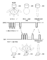
- FIG. 2 is a diagram for explaining the beam forming process.
- FIG. 14 shows an example in which the base station 400 and the terminal 450 each perform beamforming processing.
- the base station 400 corresponds to the millimeter-wave ground station 101
- the terminal 450 corresponds to the millimeter-wave on-vehicle stations 103 and 106.
- the beamforming process is mainly performed by the millimeter-wave ground station 101, and thus the base station 400 will be described here.
- the base station 400 first sweeps sectors 1 to m.
- the cycle of sweeping the 1st to m-th sectors is, for example, several msec.
- terminal 450 receives with a maximum beamwidth (360 ° directivity). Then, among the received sectors 1 to m, the sector having the highest signal strength is selected, and the result is transmitted to base station 400 (that is, the reception result is returned). For example, if the signal strength in the second sector is the highest, terminal 450 returns a reception result indicating that the signal strength is the highest in the sector.
- the time from the sweep on the base station 400 side until the reception result is returned from the terminal 450 side is, for example, 100 msec.
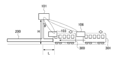
- FIG. 3 is a diagram for explaining the position estimation processing of the leading vehicle 300.
- the height of the millimeter wave ground station 101 is “H”
- the beam angle from the millimeter wave ground station 101 to the first vehicle 300 is “ ⁇ ”
- the distance from the millimeter wave ground station 101 to the first vehicle 300 is “H”. L ”.
- the height H of the millimeter-wave ground station 101 is known in advance by measurement, and the beam angle ⁇ with respect to the leading vehicle 300 can be determined by the beam forming process and the beam angle detection process.
- the distance L to the vehicle 300 can be calculated.
- the position of the second vehicle 301 can also be estimated.
- the millimeter-wave ground station 101 After estimating the position of the leading vehicle 300, the millimeter-wave ground station 101 transmits desired content data to the leading vehicle 300 in a spot manner. Upon receiving the content data transmitted from the millimeter-wave ground station 101, the millimeter-wave vehicle upper station 103 mounted on the leading vehicle 300 transmits the received content data to the vehicle mounted on the second vehicle 301 connected to the LAN. The data is transferred to the upper server 108.
- the millimeter-wave ground station 101 Prior to transmitting the content data, the millimeter-wave ground station 101 fragments the data into transmittable units. Since the continuity of the fragment of the content data is ensured by the sequence number, transmission from the first vehicle 300 to the second vehicle 301 can be performed. That is, after transmitting content data that can be transmitted to the millimeter-wave vehicle upper station 103 of the leading vehicle 300, the remaining data can be transmitted to the millimeter-wave vehicle upper station 106 of the second vehicle 301.
- the millimeter-wave ground station 101 cuts off communication with the millimeter-wave on-vehicle station 103 after transmitting enough content data to the millimeter-wave on-vehicle station 103, and is then mounted on the second vehicle 301.
- Communication with the millimeter-wave vehicle upper station 106 is started and the remaining content data is transmitted.
- the millimeter-wave on-vehicle station 106 mounted on the second vehicle 301 transfers the received content data to the on-vehicle station server 108 connected to the LAN.
- the second vehicle 301 moves from the station platform 200 to the second platform 301 when the first vehicle 300 enters the station platform 200. Until it leaves 200, the millimeter-wave ground station 101 can transmit content data. This makes it possible to lengthen the period during which the content data can be transmitted, as compared to the related art in which the content data can only be transmitted while the vehicle is stopped at the station platform 200. As a result, information can be transmitted in real time, and the amount of data that can be transmitted can be increased.
- the on-vehicle server 108 When the on-vehicle server 108 acquires all of the fragmented content data, it reconstructs the original content data.
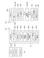
- FIG. 4 is a block diagram illustrating a schematic configuration of each of the millimeter-wave ground station 101, the content server 102, the millimeter-wave on-vehicle station 103 (106), and the on-vehicle station server 108 included in the content data transmission system 100 according to this embodiment.
- the millimeter wave ground station 101 includes an antenna 1011, a millimeter wave RF unit 1012, an internal memory 1013, a beam angle detection unit 1014, a vehicle position estimation unit 1015, an installation position information storage unit 1016, a content management unit 1017, and a terminal connection.
- a management unit 1018 and a CPU (Central Processing Unit) 1019 are provided.
- the millimeter wave RF unit 1012, the internal memory 1013, and the CPU 1019 constitute a beam forming processing unit.
- the millimeter-wave RF unit 1012 modulates the baseband signal into a 60 GHz band and transmits it, and receives a 60 GHz band millimeter wave to demodulate it into a baseband signal and output it.
- the internal memory 1013 has a ROM (Read Only Memory) storing a program for controlling the CPU 1019, and a RAM (Random Access Memory) used in the operation of the CPU 1019.
- the ROM stores a program for transmitting content data to the leading vehicle 300 and the second vehicle 301, a program for beamforming processing, and other programs required for the functions of the millimeter wave ground station 101.
- the beam angle detection unit 1014 detects an appropriate beam angle based on the result of the beam forming process.
- the vehicle position estimating unit 1015 uses the beam angle detected by the beam angle detecting unit 1014 and the installation position information of the transmitting apparatus (that is, the millimeter-wave ground station 101) to calculate the position of the leading vehicle 300 and the position of the vehicle 300 by a trigonometric function.
- the position of the vehicle 301 in both eyes is estimated.
- the installation position information storage unit 1016 stores the installation position information of the transmitting device (that is, the millimeter wave ground station 101).
- the content management unit 1017 selects content data to be transmitted to the vehicles 300 and 301 and performs fragment processing on the selected content data.
- the terminal connection management unit 1018 manages a connection between the millimeter wave vehicle upper station 103 of the vehicle 300 and the millimeter wave vehicle upper station 106 of the vehicle 301.
- the CPU 1019 controls each unit of the device according to various programs stored in the internal memory 1013.
- the content server 102 stores n pieces of content 1 to n.
- the CPU 1019 of the millimeter-wave ground station 101 downloads desired content data from the content server 102 via the LAN.
- the millimeter-wave vehicle upper station 103 (106) includes an antenna 1031, a millimeter-wave RF unit 1032, an internal memory 1033, an I / F, a power supply 1034, and a CPU 1035.
- the millimeter-wave RF unit 1032 modulates the baseband signal into a 60 GHz band and transmits the modulated signal, and receives a 60 GHz band millimeter wave to demodulate it into a baseband signal and output it.
- the internal memory 1033 has a ROM (Read Only Memory) storing a program for controlling the CPU 1035, and a RAM (Random Access Memory) used in the operation of the CPU 1035.
- the ROM stores a program for receiving the content data to the leading vehicle 300 (the second vehicle 301), a program for returning a reception result in the beam forming process of the millimeter wave ground station 101, and a LAN for storing the received content data.
- An I / F, a power supply, and the like 1034 have a LAN interface, a power supply, and the like, and perform LAN connection and supply power to each unit of the apparatus.
- the inter-vehicle connection HUB 104 (107) performs a LAN connection between the first vehicle 300 and the second vehicle 301.
- the on-board station server 108 includes a content management unit 1081 and an internal storage 1082.
- the content management unit 1081 reconstructs the fragmented content data from the millimeter-wave ground station 101 into the original content data.
- the internal storage 1082 has a large-capacity storage device such as a hard disk and a solid state drive (SSD), and stores content data.
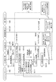
- FIG. 5 is a flowchart for explaining the operation in the content data transmission system 100 according to the present embodiment.
- the operation of the millimeter wave ground station 101 is the operation of each of the beam angle detection unit 1014, the vehicle position estimation unit 1015, the content management unit 1017, the terminal connection management unit 1018, and the CPU 1019.
- the operation of the station 101 will be described.
- the operation in the millimeter wave vehicle upper station 103 (106) the operation is mainly performed by the CPU 1035, but the operation of the CPU 1035 will be described as the operation of the millimeter wave vehicle upper station 103 (106).
- the operation is mainly performed by the content management unit 1081, but the operation of the content management unit 1081 will be described as the operation of the on-vehicle server 108.
- the millimeter-wave on-vehicle station 103 mounted on the leading vehicle 300 makes a connection request to the millimeter-wave ground station 101 when entering the station platform 200 (SB10).
- the millimeter-wave ground station 101 performs a terminal connection process by receiving a connection request from the millimeter-wave on-vehicle station 103 (SA10).
- SA11 millimeter-wave on-vehicle station 103
- the millimeter-wave ground station 101 After receiving a connection response to the millimeter-wave on-vehicle station 103, the millimeter-wave ground station 101 performs beamforming processing with the millimeter-wave on-vehicle station 103 (SA12, SB11). The millimeter-wave ground station 101 performs a beam angle detection process based on the result of performing the beamforming process with the millimeter-wave vehicle station 103 (SA13). When detecting the beam angle, the millimeter-wave ground station 101 temporarily stores the detected beam angle in the RAM of the internal memory 1013. After the beam angle detection processing, the millimeter-wave ground station 101 performs the vehicle position estimation processing to estimate the position of the leading vehicle 300. That is, the millimeter-wave ground station 101 calculates the position of the leading vehicle 300 by a trigonometric function from the installation position information stored in the installation position information storage unit 1016 and the beam angle temporarily stored in the RAM of the internal memory 1013. I do.
- the millimeter-wave ground station 101 determines whether the estimated vehicle position is within the communication range, and when determining that the vehicle position is within the communication range, requests the content server 102 to select a content (SA15).
- the communication range is a range in which the millimeter-wave ground station 101 can stably communicate with the millimeter-wave on-vehicle station 103.
- the range of the communication range may be determined by confirming a range in which communication can be performed at a predetermined speed or higher in advance, or may be determined based on the specifications of the millimeter wave ground station 101.
- the range in which the beamforming process can be performed is usually wider than the communication range.
- the content server 102 Upon receiving the content selection request from the millimeter wave ground station 101, the content server 102 responds to the content selection (SC10), and then distributes the content to the millimeter wave ground station 101 (SC11).
- SC10 content selection
- SC11 millimeter wave ground station 101
- the millimeter-wave ground station 101 performs a fragment process on the content data distributed from the content server 102 (SA16). That is, the content data distributed from the content server 102 is fragmented into distributable units.
- the millimeter-wave ground station 101 transmits the fragmented content data to the millimeter-wave vehicle upper station 103 by wireless communication using millimeter waves (SA17).
- the millimeter-wave ground station 101 After transmitting the content data to the millimeter-wave vehicle upper station 103, the millimeter-wave ground station 101 performs a terminal disconnection process (SA18), and notifies the millimeter-wave vehicle upper station 103 of the terminal disconnection (SA19). On the other hand, when the millimeter-wave ground station 101 determines that the estimated vehicle position is out of the communication range, the millimeter-wave ground station 101 performs a terminal disconnection process without acquiring content data (SA18).
- the millimeter-wave on-vehicle station 103 Upon receiving the content data transmitted from the millimeter-wave ground station 101, the millimeter-wave on-vehicle station 103 transmits the content data to the on-vehicle station server 108 mounted on the second vehicle 301 via the LAN (SB12).
- the LAN line of the first vehicle 300 and the LAN line of the second vehicle 301 are connected by inter-vehicle connection HUBs 104 and 107, and the content data is transmitted via the inter-vehicle connection HUBs 104 and 107 to the on-vehicle server. 108.
- the processing of SA12 to SA17 in the millimeter-wave ground station 101, the processing of SB11 and SB12 in the millimeter-wave vehicle upper station 103 of the leading vehicle 300, and the processing of SC10 and SC11 in the content server 102 are based on the vehicle position of the leading vehicle 300. Is repeated within the communicable range.
- the millimeter-wave ground station 101 communicates with the millimeter-wave vehicle station 106 of the second vehicle 301 in parallel with the communication of the leading vehicle 300 with the millimeter-wave vehicle station 103. Continuity is ensured by the sequence number. Therefore, data following the content data transmitted to the millimeter-wave vehicle upper station 103 is transmitted to the millimeter-wave vehicle upper station 106 of the second vehicle 301.
- the fragmented content data transmitted from the millimeter-wave ground station 101 to the millimeter-wave vehicle upper station 103 of the leading vehicle 300 and the millimeter-wave vehicle upper station 106 of the second vehicle 301 are stored in the on-vehicle station server 108. After being reconstructed.
- the beam forming process, the beam angle detecting process, and the vehicle position estimating process are performed. Since the positions of these vehicles 300 and 301 can be specified, content data can be transmitted in a spot manner. Thereby, even if there is a vehicle stopped at the adjacent station platform, stable communication can be performed without radio wave interference.
- the content data can be transmitted even when the vehicles 300 and 301 are moving, the period during which the content data can be transmitted can be made longer than before, and the information can be transmitted in real time and can be transmitted. Data capacity can be increased.
- the content data to be transmitted to the first vehicle 300 and the second vehicle 301 is fragmented into transmittable units, one content data is transmitted to the first vehicle 300 and the second vehicle 301. can do. Since the continuity of the fragment of the content data is ensured by the sequence number, when the transmission of data that can be transmitted to the leading vehicle 300 ends, the remaining data can be transmitted to the second vehicle 301.
- WiGig registered trademark
- the WiGig (registered trademark) standard uses, for example, millimeter waves in the 60 GHz band, so that radio wave interference from surroundings can be suppressed.
- the moving object is a railway vehicle, but may be an automobile, a person, or the like.
- the distance L from the millimeter-wave ground station 101 to the vehicle 300 or the like is calculated from the height H of the millimeter-wave ground station 101 and the beam angle ⁇ . If the three-dimensional position of the millimeter-wave ground station 101 is known, not only the distance L but also the accurate position of the vehicle 300 or the like may be calculated.
- the content data is transmitted in fragments, but the size of the content data can be transmitted within the time from when the leading vehicle 300 enters the communication range of the millimeter wave ground station 101 to when it exits. If it is, it does not have to be divided into fragments.
- the content data and the size of the communication area are known to the millimeter-wave ground station 101, and the speed of the leading vehicle 300 can be estimated by tracking the change in the distance L. Based on these pieces of information, the millimeter-wave ground station 101 can determine whether or not the content data can be completely transmitted within a time period from when the leading vehicle 300 enters its communication range to when it exits.
- the millimeter-wave ground station 101 estimates the positions of all the vehicles, but may estimate the positions of only some of the vehicles. In this case, the millimeter-wave ground station estimates the position of only a limited number of vehicles, such as one every few vehicles, even if all vehicles have millimeter-wave on-vehicle stations. Content data may be transmitted to the on-board station. In addition, whether to track the positions of all vehicles or only some vehicles depends on the number of millimeter-wave on-vehicle stations currently communicating with the millimeter-wave ground station and whether communication is congested. Switching may be performed in response. In this way, the load on the millimeter-wave ground station 101 is adjusted particularly when the number of vehicles managed by the millimeter-wave ground station 101 is large, such as when many trains composed of many vehicles are approaching. be able to.
- the data transmitted by the millimeter-wave ground station 101 is content data such as an advertisement image, but may be other data.
- the data transmission device and the data transmission method according to the present invention are applicable to a content data transmission device or the like that transmits content data such as an advertisement video to a moving object such as a railway car.
- REFERENCE SIGNS LIST 100 Content data transmission system 101 Millimeter-wave ground station 102 Content server 103, 106 Millimeter-wave on-vehicle station 104, 107 HUB for connection between vehicles 108 On-board server 200 Station platform 300, 301 Railway vehicle 1011, 1031 Antenna 1012, 1032 Millimeter wave RF unit 1013, 1033 Internal memory 1014 Beam angle detection unit 1015 Vehicle position estimation unit 1016 Installation position information storage unit 1017 Content management unit 1018 Terminal connection management unit 1019, 1035 CPU 1034 I / F, power supply, etc. 1081 Content management unit 1082 Internal storage
Landscapes
- Engineering & Computer Science (AREA)
- Mechanical Engineering (AREA)
- Computer Networks & Wireless Communication (AREA)
- Signal Processing (AREA)
- Remote Sensing (AREA)
- Physics & Mathematics (AREA)
- Radar, Positioning & Navigation (AREA)
- General Physics & Mathematics (AREA)
- Aviation & Aerospace Engineering (AREA)
- Life Sciences & Earth Sciences (AREA)
- Sustainable Development (AREA)
- Sustainable Energy (AREA)
- Power Engineering (AREA)
- Transportation (AREA)
- Mobile Radio Communication Systems (AREA)
- Train Traffic Observation, Control, And Security (AREA)
Abstract
データ送信装置に対応するミリ波地上局(101)は、車両(300)に設けられた端末に対応するミリ波車上局(103)との間でビームフォーミング処理を行い、その結果に基づきビーム角度を検出し、検出したビーム角度とミリ波地上局(101)の設置位置情報とから車両(300)の位置を推定し、位置推定した車両(300)に向けてスポット的にコンテンツデータを送信する。コンテンツデータを送信する際、必要に応じて送信可能な単位にフラグメント化する。また、コンテンツデータの送信を、ミリ波を用いて行う。
Description
本発明は、例えば鉄道車両に広告映像等のコンテンツデータを送信するデータ送信装置及びデータ送信方法に関する。
従来、鉄道車両内で配信される広告映像等のコンテンツデータの更新は、通常、車庫で運行時間外にハードディスク等の記憶媒体を入れ替えるか、または停車中にWiFi(登録商標)等による無線通信により入れ替えることで行っている。
WiFi(登録商標)は広域をカバーするには優れているが、隣の駅ホームに停車している鉄道車両との無線による電波干渉や複数車両とのオーバーリーチによる電波干渉で安定に通信させることが難しい。また、鉄道車両が走行しながら通信する場合は、アンテナの指向性を広域にカバーさせる必要があるが、一般的なオムニアンテナ(無指向性アンテナ)の場合、やはり周囲からの電波干渉を受けやすくなってしまう。
隣の駅ホームに停車している鉄道車両との電波干渉や複数車両との間の電波干渉を受け難くするようにしたものとして、例えば非特許文献1に記載された60GHz帯のミリ波を使用したシステムがある。このシステムは、地上装置と車上装置とから構成され、地上装置は、終端駅や折り返し駅等の停車時間が長い場所や車庫から営業線への出庫線等の特定場所に、車上装置は、車両の運転台にそれぞれ設置される。地上装置と車上装置間の通信にミリ波を用いることで、地上装置と車上装置はオーバーリーチ干渉を殆ど受けることなく安定した通信を行える。
「60GHz帯ミリ波を利用した既存システム」、2014年12月、三菱電機株式会社、p35-p39、インターネット<URL: http://www.soumu.go.jp/main_content/000331036.pdf>
しかしながら、上記非特許文献1で開示されたシステムは、鉄道車両がホームに停車している間に該車両に対してコンテンツデータの送信を行うので、情報のリアルタイムでの送信には不適格であり、また送信可能なデータ量が制限されるという課題がある。ここで、リアルタイムで送信されるべきコンテンツデータの例としては、災害警報などの緊急を要する情報や、ニュース速報などが挙げられる。
本発明は、他の移動体と電波干渉することなく安定した通信を行うことができるとともに、情報のリアルタイムでの送信が可能で、また送信可能なデータ容量の増大が図れるデータ送信装置及びデータ送信方法を提供することを目的とする。
本発明のデータ送信装置は、移動体に設けられた端末との間でビームフォーミング処理を行うビームフォーミング処理部と、前記ビームフォーミング処理の結果に基づきビーム角度を検出するビーム角度検出部と、前記ビーム角度と本送信装置の設置位置情報とから前記移動体の位置を推定する移動体位置推定部と、を備え、前記推定した移動体の位置が、前記本送信装置の通信圏内であるか否かを判定し、前記通信圏内であれば、前記移動体に向けて所望のデータを送信する。
上記構成によれば、移動体が動いているときでも該移動体の位置を特定して、該移動体に向けてスポット的にデータを送信するので、電波干渉することなく安定した通信を行うことができる。また、移動体が動いているときでもデータの送信ができることから、従来よりもデータの送信期間を長くとることができ、これにより情報のリアルタイムでの送信が可能となり、また送信可能なデータ容量の増大が図れる。
本発明のデータ送信装置の一態様として例えば、本送信装置の設置位置情報は予め記憶されている。
上記構成によれば、本送信装置の設置位置情報があり、また本送信装置から移動体に対するビーム角度を検出できるので、三角関数により本送信装置と移動体との間の距離を算出でき、この結果から移動体の位置を推定することができる。
本発明のデータ送信装置の一態様として例えば、前記所望のデータを、送信可能な単位にフラグメント化して送信する。
上記構成によれば、データを分割することで、移動体の移動量に応じた分のデータを送信することができる。
本発明のデータ送信装置の一態様として例えば、前記移動体は、所定のグループを構成する複数の移動体であり、前記グループを構成する移動体の1つについて、推定した前記移動体の位置と前記データの容量とに基づき、前記移動体の1つが前記通信圏内に滞在している間に、前記データの送信を完了させることができるか否かを判定し、前記移動体の1つが通信圏内に滞在している間に前記データの送信を完了させることができないと判定した場合、前記データをフラグメント化し、前記移動体の1つおよび前記グループを構成する他の移動体に対して、それぞれの移動体が前記通信圏内に滞在している間に、前記データの異なるフラグメントを送信する。
上記構成によれば、1つの移動体が通信圏内に滞在している間にデータの送信が完了する可能性が低い場合に、その1つの移動体と同じグループに属する複数の移動体にデータをフラグメント化して送信することができる。
本発明のデータ送信装置の一態様として例えば、前記移動体の1つが通信圏内に滞在している間に前記データの送信を完了させることができると判定した場合、前記データをフラグメント化せずに前記移動体の1つに送信する。
上記構成によれば、移動体の1つに対してデータを送信することが可能である場合にはフラグメント化を行わない。そのため、同じグループに属する他の移動体との通信の管理にかかる負担を軽減することができる。
本発明のデータ送信装置の一態様として例えば、前記移動体は鉄道車両であり、前記グループは互いに連結された前記鉄道車両の集合である。
上記構成によれば、例えば鉄道車両が複数両連結されている場合、先頭の車両が駅ホームに進入してきたときから、最後尾の車両が駅ホームを去るときまでの間、先頭の車両から順にデータを送信することができる。したがって、駅ホームに停車中でしかデータを送信することができない従来技術に比べて、データの送信期間を長くとることができる。
本発明のデータ送信装置の一態様として例えば、本送信装置はミリ波を用いて前記データを送信する。
上記構成によれば、ミリ波を用いてデータを送信することで、大容量のデータを高速に送信することができる。また、周囲からの電波干渉を低く抑えることができる。
本発明のデータ送信方法は、移動体に設けられた端末との間でビームフォーミング処理を行い、前記ビームフォーミング処理の結果に基づきビーム角度を検出し、前記ビーム角度と本送信方法を実行する装置の設置位置情報とから前記移動体の位置を推定し、前記推定した移動体の位置が、前記本送信方法を実行する装置の通信圏内であるか否か判定し、前記通信圏内であれば、前記移動体に向けて所望のデータを送信する。
上記方法によれば、移動体が動いているときでも該移動体の位置を特定して、該移動体に向けてスポット的にデータを送信するので、電波干渉することなく安定した通信を行うことができる。また、移動体が動いているときでもデータの送信ができることから、従来よりもデータの送信期間を長くとることができ、これにより情報のリアルタイムでの送信が可能となり、また送信可能なデータ容量の増大が図れる。
本発明のデータ送信装置及びデータ送信方法は、他の移動体と電波干渉することなく安定した通信を行うことができるとともに、情報のリアルタイムでの送信が可能で、また送信可能なデータ容量の増大が図れる。
以下、本発明を実施するための好適な実施の形態について、図面を参照して詳細に説明する。
図1は、本発明の一実施形態に係るコンテンツデータ送信システム100の概略構成を示すブロック図である。同図において、本実施形態に係るコンテンツデータ送信システム100は、駅ホーム200の特定場所に設置されるミリ波地上局(データ送信装置)101と、ミリ波地上局101とLAN接続され、複数のコンテンツを記憶したコンテンツサーバ102と、鉄道車両300に設置され、ミリ波地上局101と通信を行うミリ波車上局(端末)103と、鉄道車両300に設置され、ミリ波車上局103とLAN接続された車両間接続用HUB104と、鉄道車両301に設置され、ミリ波地上局101と通信を行うミリ波車上局(端末)106と、鉄道車両301に設置され、ミリ波車上局106とLAN接続された車両間接続用HUB107と、鉄道車両301に設置され、車両間接続用HUB107にLAN接続された車上局サーバ108と、を備える。
ここで、本実施形態では移動体を2両編成の鉄道車両としており、鉄道車両300は先頭車両、鉄道車両301は2両目車両である。以下、鉄道車両300,301を単に“車両”と呼ぶこととする。なお、車両の編成数に限定はなく、最後尾にあたる車両に車上局サーバ108を搭載する以外は、先頭の車両300と同様の構成となる。車上局サーバ108はLAN接続して使用することから、例えば5両編成であれば、最後尾の5両目の車両に持ってくることになる。なお、車上局サーバ108は他の車両と通信できる限り、必ずしも最後尾の車両に設置する必要はない。ただし、一般的な鉄道車両では、運転席等が設けられる先頭・最後尾の車両と、客席のみが設けられる中間の車両では構成が異なるため、先頭もしくは最後尾に車上局サーバ108を配置した方が、列車の編成の自由度は高まる。
ミリ波地上局101とコンテンツサーバ102は、双方とも固定設置されるので、これらの間のLAN接続は有線が望ましい。また、車両300,301それぞれにおけるLAN接続と、車両300と車両301間のLAN接続は有線又は無線のいずれでもよい。但し、車両300と車両301を連結したり切り離したりすることから、作業性の点で無線の方が望ましい。
ミリ波地上局101とミリ波車上局103,106との間の通信には、ミリ波を用いる無線通信が使用される。ミリ波を用いる無線通信の具体例としては、WiGig(登録商標)規格に準拠したミリ波高速通信が考えられる。ミリ波を用いる無線通信を行うことで、大容量のコンテンツデータを高速に送信することができる。なお、図1では、ミリ波地上局101と先頭の車両300のミリ波車上局103との間の通信が切断されていて、ミリ波地上局101と2両目の車両301のミリ波車上局106との間の通信が行われている状態を示している。
ミリ波地上局101は、例えばミリ波車上局106との通信において、ミリ波車上局106からの接続要求があると端末接続処理を行う。そして、接続可能となった後、ミリ波車上局106との間でビームフォーミング処理を行い、その結果に基づいて適切なビーム角度を検出する。そして、本送信装置(即ち、ミリ波地上局101)が予め記憶している設置位置情報を用いて、三角関数により本送信装置から2両目の車両301までの距離を算出し、算出した2両目の車両301までの距離から2両目の車両301の位置を推定する。そして、位置推定した2両目の車両301に向けて所望のコンテンツデータを送信する。上記ビームフォーミング処理、ビーム角度検出処理及び車両位置推定処理は、先頭の車両300に搭載されたミリ波車上局103との間においても同様に行われる。
ここで、ビームフォーミング処理について説明する。図2は、ビームフォーミング処理を説明するための図である。同図は、基地局400と端末450のそれぞれにおいてビームフォーミング処理を行っている例である。なお、基地局400はミリ波地上局101に相当し、端末450はミリ波車上局103,106に相当する。本実施形態に係るコンテンツデータ送信システム100では、ビームフォーミング処理は、主にミリ波地上局101が行うので、ここでは基地局400側について説明する。基地局400は、まず1~m番のセクタをスイープする。1~m番のセクタをスイープする周期は例えば数msecである。基地局400のセクタスイープに対し、端末450は最大ビーム幅(360°の指向性)で受信する。そして、受信した1~m番のセクタのうち、最も信号強度の大きなものを選択し、その結果を基地局400に送信する(即ち、受信結果を返信する)。例えば、2番目のセクタにおける信号強度が最も大きければ、端末450は当該セクタにおいて信号強度が最も大きかったことを示す受信結果を返信する。なお、基地局400側のスイープから端末450側から受信結果が返信されるまでの時間は、例えば100msecである。
次に、車両の位置推定処理について説明する。図3は、先頭の車両300の位置推定処理を説明するための図である。同図において、ミリ波地上局101の高さを「H」、ミリ波地上局101から先頭の車両300に対するビーム角度を「θ」、ミリ波地上局101から先頭の車両300までの距離を「L」とする。ミリ波地上局101の高さHは予め測定して分かっており、先頭の車両300に対するビーム角度θはビームフォーミング処理及びビーム角度検出処理で分かるので、三角関数よりミリ波地上局101から先頭の車両300までの距離Lを算出することができる。当然ながら同様の処理を行うことで2両目の車両301の位置も推定することができる。
ミリ波地上局101は、先頭の車両300の位置を推定した後、先頭の車両300に向けてスポット的に所望のコンテンツデータを送信する。先頭の車両300に搭載されたミリ波車上局103は、ミリ波地上局101から送信されたコンテンツデータを受信すると、受信したコンテンツデータをLAN接続された2両目の車両301に搭載された車上局サーバ108に転送する。
ミリ波地上局101は、コンテンツデータを送信するに先立ち、送信可能な単位にフラグメント化する。コンテンツデータのフラグメントはシーケンス番号で連続性が担保されるので、先頭の車両300から2両目の車両301に亘る送信が可能となる。即ち、先頭の車両300のミリ波車上局103に送信可能な分のコンテンツデータを送信した後、残りを2両目の車両301のミリ波車上局106に送信することができる。ミリ波地上局101は、ミリ波車上局103に送信可能な分のコンテンツデータを送信した後、ミリ波車上局103との間の通信を切断し、次いで2両目の車両301に搭載されたミリ波車上局106との通信を開始して残りのコンテンツデータを送信する。2両目の車両301に搭載されたミリ波車上局106は、ミリ波地上局101から送信されたコンテンツデータを受信すると、受信したコンテンツデータをLAN接続された車上局サーバ108に転送する。
先頭の車両300と2両目の車両301の位置推定を行うことと、コンテンツデータをフラグメント化することで、先頭の車両300が駅ホーム200に進入してきたときから、2両目の車両301が駅ホーム200を去るときまでの間、ミリ波地上局101は、コンテンツデータを送信することができる。これにより、駅ホーム200に停車中でしかコンテンツデータを送信できなかった従来技術と比べて、コンテンツデータを送信できる期間を長くとることができる。これにより、情報のリアルタイムでの送信が可能となるとともに、送信可能なデータ容量の増大が図れる。
車上局サーバ108は、フラグメント化されたコンテンツデータの全てを取得すると、元のコンテンツデータに再構成する。
図4は、本実施形態に係るコンテンツデータ送信システム100を構成するミリ波地上局101、コンテンツサーバ102、ミリ波車上局103(106)及び車上局サーバ108それぞれの概略構成を示すブロック図である。同図において、ミリ波地上局101は、アンテナ1011、ミリ波RF部1012、内部メモリ1013、ビーム角度検出部1014、車両位置推定部1015、設置位置情報記憶部1016、コンテンツ管理部1017、端末コネクション管理部1018及びCPU(Central Processing Unit)1019を備える。なお、ミリ波RF部1012、内部メモリ1013及びCPU1019は、ビームフォーミング処理部を構成する。
ミリ波RF部1012は、ベースバンド信号を60GHz帯に変調して送信し、また60GHz帯のミリ波を受信してベースバンド信号に復調して出力する。内部メモリ1013は、CPU1019を制御するプログラムを記憶したROM(Read Only Memory)と、CPU1019の動作において使用されるRAM(Random Access memory)と、を有する。ROMには、先頭の車両300及び2両目の車両301にコンテンツデータを送信するためのプログラム、ビームフォーミング処理用のプロラム等のミリ波地上局101の機能に必要なプログラムが記憶されている。
ビーム角度検出部1014は、ビームフォーミング処理の結果に基づき適切なビーム角度を検出する。車両位置推定部1015は、ビーム角度検出部1014で検出されたビーム角度と本送信装置(即ち、ミリ波地上局101)の設置位置情報を用いて、三角関数により先頭の車両300の位置と2両目の車両301の位置を推定する。設置位置情報記憶部1016は、本送信装置(即ち、ミリ波地上局101)の設置位置情報を記憶する。コンテンツ管理部1017は、車両300,301に送信するコンテンツデータの選択及び選択したコンテンツデータのフラグメント処理を行う。端末コネクション管理部1018は、車両300のミリ波車上局103と車両301のミリ波車上局106とのコネクションを管理する。CPU1019は、内部メモリ1013に記憶されている各種プログラムに従って装置各部を制御する。
コンテンツサーバ102は、n個のコンテンツ1~nを記憶する。ミリ波地上局101のCPU1019は、所望のコンテンツデータをLAN経由でコンテンツサーバ102からダウンロードする。
ミリ波車上局103(106)は、アンテナ1031、ミリ波RF部1032、内部メモリ1033、I/F、電源等1034及びCPU1035を備える。ミリ波RF部1032は、ベースバンド信号を60GHz帯に変調して送信し、また60GHz帯のミリ波を受信してベースバンド信号に復調して出力する。内部メモリ1033は、CPU1035を制御するプログラムを記憶したROM(Read Only Memory)と、CPU1035の動作において使用されるRAM(Random Access memory)とを有する。ROMには、先頭の車両300(2両目の車両301)にコンテンツデータを受信するためのプログラム、ミリ波地上局101のビームフォーミング処理における受信結果を返信するためのプログラム、受信したコンテンツデータをLAN経由で車上局サーバ108に転送するプログラム等のミリ波車上局103(106)の機能に必要なプログラムが記憶されている。I/F、電源等1034は、LAN用のインタフェースや電源等を有し、LAN接続や装置各部に電源の供給を行う。
車両間接続用HUB104(107)は、先頭の車両300と2両目の車両301の間でLAN接続を行う。車上局サーバ108は、コンテンツ管理部1081及び内部ストレージ1082を有する。コンテンツ管理部1081は、ミリ波地上局101からのフラグメント化されたコンテンツデータを元のコンテンツデータに再構成する。内部ストレージ1082は、例えばハードディスク、SSD(Solid State Drive)等の大容量の記憶装置を有し、コンテンツデータを記憶する。
次に、本実施形態に係るコンテンツデータ送信システム100の動作を説明する。図5は、本実施形態に係るコンテンツデータ送信システム100における動作を説明するためのフロー図である。ここで、ミリ波地上局101における動作は、ビーム角度検出部1014、車両位置推定部1015、コンテンツ管理部1017、端末コネクション管理部1018及びCPU1019それぞれの動作となるが、それぞれの動作をミリ波地上局101の動作として説明する。また、ミリ波車上局103(106)においては動作の主体がCPU1035であるが、CPU1035の動作をミリ波車上局103(106)の動作として説明する。また、車上局サーバ108においては動作の主体がコンテンツ管理部1081であるが、コンテンツ管理部1081の動作を車上局サーバ108の動作として説明する。
図5において、先頭の車両300に搭載されたミリ波車上局103は、駅ホーム200に入ってくるとミリ波地上局101に対して接続要求する(SB10)。ミリ波地上局101は、ミリ波車上局103から接続要求を受けることで端末接続処理を行う(SA10)。ミリ波地上局101は、端末接続処理が終了すると、ミリ波車上局103に対して接続応答する(SA11)。
ミリ波地上局101は、ミリ波車上局103に対して接続応答した後、ミリ波車上局103との間でビームフォーミング処理を行う(SA12,SB11)。ミリ波地上局101は、ミリ波車上局103との間でビームフォーミング処理を行った結果から、ビーム角度検出処理を行う(SA13)。ミリ波地上局101は、ビーム角度を検出すると、検出したビーム角度を内部メモリ1013のRAMに一時的に記憶する。ミリ波地上局101は、ビーム角度検出処理後、車両位置推定処理を行い、先頭車両300の位置を推定する。即ち、ミリ波地上局101は、設置位置情報記憶部1016に記憶されている設置位置情報と内部メモリ1013のRAMに一時的に記憶したビーム角度から、三角関数により先頭の車両300の位置を計算する。
次いで、ミリ波地上局101は、推定した車両位置が通信圏内かどうか判定し、通信圏内であると判断した場合、コンテンツサーバ102に対してコンテンツ選択要求する(SA15)。なお、通信圏内とは、ミリ波地上局101がミリ波車上局103と安定して通信することができる範囲である。通信圏の範囲については、予め所定の速度以上で通信できる範囲を確認することで決定してもよいし、ミリ波地上局101の仕様から決定するとしてもよい。なお、ビームフォーミング処理を行うことができる範囲は、通常は通信圏よりも広い。ビームフォーミングに要する通信量は少ないため、ミリ波地上局101とミリ波車上局103が通信することができれば、その通信速度が遅くともビームフォーミング処理は実現できるためである。コンテンツサーバ102は、ミリ波地上局101からコンテンツ選択要求を受けると、コンテンツ選択応答し(SC10)、次いでミリ波地上局101にコンテンツを配信する(SC11)。ミリ波地上局101は、コンテンツサーバ102から配信されたコンテンツデータに対してフラグメント処理する(SA16)。即ち、コンテンツサーバ102から配信されたコンテンツデータを配信可能な単位にフラグメント化する。ミリ波地上局101は、フラグメント化したコンテンツデータを、ミリ波を用いる無線通信により、ミリ波車上局103に送信する(SA17)。
ミリ波地上局101は、コンテンツデータをミリ波車上局103に送信した後、端末切断処理を行い(SA18)、ミリ波車上局103に対して端末切断通知を行う(SA19)。一方、ミリ波地上局101は、推定した車両位置が通信圏外であると判断した場合、コンテンツデータを取得することなく端末切断処理を行う(SA18)。
ミリ波車上局103は、ミリ波地上局101から送信されたコンテンツデータを受信すると、LAN経由で2両目の車両301に搭載された車上局サーバ108に送信する(SB12)。先頭の車両300のLAN回線と2両目の車両301のLAN回線は、車両間接続用HUB104,107で接続されており、これらの車両間接続用HUB104,107を介してコンテンツデータが車上局サーバ108に転送される。
ミリ波地上局101におけるSA12~SA17の処理と、先頭の車両300のミリ波車上局103におけるSB11,12の処理と、コンテンツサーバ102におけるSC10,11の処理は、先頭の車両300の車両位置が通信可能な範囲内であれば、繰り返し行われる。
ミリ波地上局101は、先頭の車両300のミリ波車上局103との通信と並行して2両目の車両301のミリ波車上局106との通信を行っており、コンテンツデータのフラグメントはシーケンス番号で連続性が担保されている。このため、ミリ波車上局103に送信されたコンテンツデータに続くデータが2両目の車両301のミリ波車上局106に送信される。
ミリ波地上局101から、先頭の車両300のミリ波車上局103及び2両目の車両301のミリ波車上局106に送信されたフラグメント化されたコンテンツデータは、車上局サーバ108に格納された後、再構成される。
このように、本実施形態に係るコンテンツデータ送信システム100によれば、ビームフォーミング処理、ビーム角度検出処理及び車両位置推定処理により、先頭の車両300と2両目の車両301が移動しているときでも、これらの車両300,301の位置を特定できるので、スポット的にコンテンツデータを送信できる。これにより、隣の駅ホームに停車している車両があったとしても電波干渉することなく安定した通信を行うことができる。また、車両300,301が動いているときでもコンテンツデータの送信ができるので、従来よりもコンテンツデータを送信できる期間を長くとることができ、情報のリアルタイムでの送信が可能となるとともに、送信可能なデータ容量の増大が図れる。
また、先頭の車両300と2両目の車両301に向けて送信するコンテンツデータを、送信可能な単位にフラグメント化するので、1つのコンテンツデータを先頭の車両300と2両目の車両301に亘って送信することができる。コンテンツデータのフラグメントはシーケンス番号で連続性が担保されるので、先頭の車両300に送信可能な分のデータ送信が終了すると、残りのデータを2両目の車両301に送信することができる。
また、コンテンツデータの送信に、WiGig(登録商標)規格に準拠する無線通信など、ミリ波を用いる無線通信を使用するので、大容量のコンテンツデータを高速に送信することができる。また、WiGig(登録商標)規格は例えば60GHz帯のミリ波を使用するので、周囲からの電波干渉を低く抑えることができる。
なお、本実施形態では、移動体を鉄道車両としたが、自動車や人物等であってもよい。
以上、本発明の一実施形態を詳細に説明したが、本発明の精神と範囲を逸脱することなく様々な変更や修正を加えることができることは当業者にとって明らかである。
上記実施の形態では、ミリ波地上局101の高さHとビーム角度θから、ミリ波地上局101から車両300等までの距離Lを算出していた。ミリ波地上局101の三次元位置が既知であるならば、距離Lのみならず車両300等の正確な位置を算出してもよい。
上記実施の形態では、コンテンツデータをフラグメントに分けて送信していたが、コンテンツデータの大きさが、先頭車両300がミリ波地上局101の通信圏に入ってから出るまでの時間内に送信可能であれば、フラグメントに分けなくともよい。ミリ波地上局101にとって、コンテンツデータと通信圏の大きさは既知であり、先頭車両300の速度は距離Lの変化を追跡することで推測できる。これらの情報に基づき、ミリ波地上局101は、先頭車両300が自身の通信圏に入ってから出るまでの時間内に、コンテンツデータを送り切ることができるか判断することができる。
上記実施の形態では、ミリ波地上局101は、全ての車両について位置を推定していたが、一部の車両のみ位置を推定するとしても良い。この場合、ミリ波地上局は、たとえ全ての車両がミリ波車上局を備えているとしても、数台おきに1台など、限られた車両についてのみ位置を推定し、その車両のミリ波車上局に対してコンテンツデータを送信しても良い。また、全ての車両の位置を追跡するか一部の車両のみを追跡するかを、ミリ波地上局が現在通信しているミリ波車上局の数や、通信が混雑しているか否かに応じて切り替えてもよい。このようにすることで、特に多くの車両から構成される列車が多数接近している場合など、ミリ波地上局101が管理する車両数が多い場合に、ミリ波地上局101の負荷を調整することができる。
上記実施の形態では、ミリ波地上局101が送信するデータは広告映像等のコンテンツデータであったが、他のデータであっても構わない。
本発明を詳細にまた特定の実施態様を参照して説明したが、本発明の精神と範囲を逸脱することなく様々な変更や修正を加えることができることは当業者にとって明らかである。
本出願は、2018年8月14日出願の日本特許出願(特願2018-152667)に基づくものであり、その内容はここに参照として援用される。
本発明に係るデータ送信装置及びデータ送信方法は、鉄道車両等の移動体に対して広告映像等のコンテンツデータを送信するコンテンツデータ送信装置等に適用可能である。
100 コンテンツデータ送信システム
101 ミリ波地上局
102 コンテンツサーバ
103,106 ミリ波車上局
104,107 車両間接続用HUB
108 車上局サーバ
200 駅ホーム
300,301 鉄道車両
1011,1031 アンテナ
1012,1032 ミリ波RF部
1013,1033 内部メモリ
1014 ビーム角度検出部
1015 車両位置推定部
1016 設置位置情報記憶部
1017 コンテンツ管理部
1018 端末コネクション管理部
1019,1035 CPU
1034 I/F、電源等
1081 コンテンツ管理部
1082 内部ストレージ
101 ミリ波地上局
102 コンテンツサーバ
103,106 ミリ波車上局
104,107 車両間接続用HUB
108 車上局サーバ
200 駅ホーム
300,301 鉄道車両
1011,1031 アンテナ
1012,1032 ミリ波RF部
1013,1033 内部メモリ
1014 ビーム角度検出部
1015 車両位置推定部
1016 設置位置情報記憶部
1017 コンテンツ管理部
1018 端末コネクション管理部
1019,1035 CPU
1034 I/F、電源等
1081 コンテンツ管理部
1082 内部ストレージ
Claims (8)
- 移動体に設けられた端末との間でビームフォーミング処理を行うビームフォーミング処理部と、
前記ビームフォーミング処理の結果に基づきビーム角度を検出するビーム角度検出部と、
前記ビーム角度と本送信装置の設置位置情報とから前記移動体の位置を推定する移動体位置推定部と、を備え、
前記推定した移動体の位置が、前記本送信装置の通信圏内であるか否か判定し、
前記通信圏内であれば、前記移動体に向けて所望のデータを送信する、
データ送信装置。 - 請求項1に記載のデータ送信装置であって、
本送信装置の設置位置情報は予め記憶されている、
データ送信装置。 - 請求項1又は請求項2に記載のデータ送信装置であって、
前記所望のデータを、送信可能な単位にフラグメント化して送信する、
データ送信装置。 - 請求項3に記載のデータ送信装置であって、
前記移動体は、所定のグループを構成する複数の移動体であり、
前記グループを構成する移動体の1つについて、推定した前記移動体の位置と前記データの容量とに基づき、前記移動体の1つが前記通信圏内に滞在している間に、前記データの送信を完了させることができるか否かを判定し、
前記移動体の1つが通信圏内に滞在している間に前記データの送信を完了させることができないと判定した場合、前記データをフラグメント化し、
前記移動体の1つおよび前記グループを構成する他の移動体に対して、それぞれの移動体が前記通信圏内に滞在している間に、前記データの異なるフラグメントを送信する、
データ送信装置。 - 請求項4に記載のデータ送信装置であって、
前記移動体の1つが通信圏内に滞在している間に前記データの送信を完了させることができると判定した場合、前記データをフラグメント化せずに前記移動体の1つに送信する、
データ送信装置。 - 請求項4又は請求項5に記載のデータ送信装置であって、
前記移動体は鉄道車両であり、前記グループは互いに連結された前記鉄道車両の集合である、
データ送信装置。 - 請求項1から請求項6のいずれか一項に記載のデータ送信装置であって、
本送信装置はミリ波を用いて前記データを送信する、
データ送信装置。 - 移動体に設けられた端末との間でビームフォーミング処理を行い、
前記ビームフォーミング処理の結果に基づきビーム角度を検出し、
前記ビーム角度と本送信方法を実行する装置の設置位置情報とから前記移動体の位置を推定し、
前記推定した移動体の位置が、前記本送信方法を実行する装置の通信圏内であるか否か判定し、
前記通信圏内であれば、前記移動体に向けて所望のデータを送信する、
データ送信方法。
Priority Applications (3)
| Application Number | Priority Date | Filing Date | Title |
|---|---|---|---|
| CN201980053129.XA CN112567786B (zh) | 2018-08-14 | 2019-05-31 | 数据发送装置和数据发送方法 |
| US17/268,236 US20210316770A1 (en) | 2018-08-14 | 2019-05-31 | Data transmitting device, and data transmitting method |
| EP19849365.2A EP3840451A4 (en) | 2018-08-14 | 2019-05-31 | DATA TRANSMISSION DEVICE, AND DATA TRANSMISSION PROCESS |
Applications Claiming Priority (2)
| Application Number | Priority Date | Filing Date | Title |
|---|---|---|---|
| JP2018152667A JP7145447B2 (ja) | 2018-08-14 | 2018-08-14 | データ送信装置及びデータ送信方法 |
| JP2018-152667 | 2018-08-14 |
Publications (1)
| Publication Number | Publication Date |
|---|---|
| WO2020035985A1 true WO2020035985A1 (ja) | 2020-02-20 |
Family
ID=69524824
Family Applications (1)
| Application Number | Title | Priority Date | Filing Date |
|---|---|---|---|
| PCT/JP2019/021873 WO2020035985A1 (ja) | 2018-08-14 | 2019-05-31 | データ送信装置及びデータ送信方法 |
Country Status (5)
| Country | Link |
|---|---|
| US (1) | US20210316770A1 (ja) |
| EP (1) | EP3840451A4 (ja) |
| JP (1) | JP7145447B2 (ja) |
| CN (1) | CN112567786B (ja) |
| WO (1) | WO2020035985A1 (ja) |
Families Citing this family (2)
| Publication number | Priority date | Publication date | Assignee | Title |
|---|---|---|---|---|
| GB2588819A (en) | 2019-11-10 | 2021-05-12 | Bluwireless Tech Ltd | Communication system and method for communication with vehicle based node |
| CN216013977U (zh) * | 2021-08-09 | 2022-03-11 | 中车长春轨道客车股份有限公司 | 一种数据传输系统和轨道车辆 |
Citations (4)
| Publication number | Priority date | Publication date | Assignee | Title |
|---|---|---|---|---|
| JPH11146464A (ja) * | 1997-09-02 | 1999-05-28 | Sumitomo Electric Ind Ltd | 地上通信装置及び車載通信装置並びに路車間データ通信システム |
| JP2014142255A (ja) * | 2013-01-24 | 2014-08-07 | Sony Corp | 情報処理装置、情報処理方法およびプログラム |
| WO2018100684A1 (ja) * | 2016-11-30 | 2018-06-07 | マクセル株式会社 | モバイル端末連携システム及びサービス情報配信方法 |
| JP2018152667A (ja) | 2017-03-10 | 2018-09-27 | キヤノン株式会社 | 画像形成装置 |
Family Cites Families (12)
| Publication number | Priority date | Publication date | Assignee | Title |
|---|---|---|---|---|
| US4914441A (en) * | 1988-08-29 | 1990-04-03 | Raytheon Company | Method of processing in a pulse doppler radar |
| JP3737474B2 (ja) * | 2002-12-05 | 2006-01-18 | 株式会社バッファロー | コンテンツの予約受取システム、アクセスポイント、データ受取システム、および、コンテンツの予約受取方法 |
| CN103095356B (zh) * | 2011-11-04 | 2015-09-23 | 上海瀚讯无线技术有限公司 | 一种波束成形方法、基站和交通运输装置 |
| KR101374350B1 (ko) * | 2012-12-04 | 2014-03-19 | 한국철도기술연구원 | 열차 위치 검출 장치 |
| JP5881896B2 (ja) * | 2013-05-10 | 2016-03-09 | 三菱電機株式会社 | 通信装置 |
| US10061027B2 (en) * | 2014-02-25 | 2018-08-28 | Adsys Controls, Inc. | Laser navigation system and method |
| US10205670B2 (en) * | 2014-09-12 | 2019-02-12 | Qualcomm Incorporated | Selective storage and deletion in mobile content delivery networks |
| US9987974B2 (en) * | 2016-06-24 | 2018-06-05 | Ford Global Technologies, Llc | Lighting system having pointer device |
| US10511091B2 (en) * | 2016-07-15 | 2019-12-17 | Qualcomm Incorporated | Dynamic beam steering for unmanned aerial vehicles |
| US10403141B2 (en) * | 2016-08-19 | 2019-09-03 | Sony Corporation | System and method for processing traffic sound data to provide driver assistance |
| JP6916609B2 (ja) * | 2016-11-21 | 2021-08-11 | パナソニック インテレクチュアル プロパティ コーポレーション オブ アメリカPanasonic Intellectual Property Corporation of America | 交差点情報配信装置及び交差点情報配信方法 |
| CN107635189B (zh) * | 2017-09-15 | 2020-03-13 | 中国联合网络通信集团有限公司 | 一种波束选择方法及装置 |
-
2018
- 2018-08-14 JP JP2018152667A patent/JP7145447B2/ja active Active
-
2019
- 2019-05-31 EP EP19849365.2A patent/EP3840451A4/en active Pending
- 2019-05-31 WO PCT/JP2019/021873 patent/WO2020035985A1/ja unknown
- 2019-05-31 US US17/268,236 patent/US20210316770A1/en active Pending
- 2019-05-31 CN CN201980053129.XA patent/CN112567786B/zh active Active
Patent Citations (4)
| Publication number | Priority date | Publication date | Assignee | Title |
|---|---|---|---|---|
| JPH11146464A (ja) * | 1997-09-02 | 1999-05-28 | Sumitomo Electric Ind Ltd | 地上通信装置及び車載通信装置並びに路車間データ通信システム |
| JP2014142255A (ja) * | 2013-01-24 | 2014-08-07 | Sony Corp | 情報処理装置、情報処理方法およびプログラム |
| WO2018100684A1 (ja) * | 2016-11-30 | 2018-06-07 | マクセル株式会社 | モバイル端末連携システム及びサービス情報配信方法 |
| JP2018152667A (ja) | 2017-03-10 | 2018-09-27 | キヤノン株式会社 | 画像形成装置 |
Non-Patent Citations (4)
| Title |
|---|
| "The Existing System Using 60 GHz Millimeter-Wave", MITSUBISHI ELECTRIC CORPORATION, December 2014 (2014-12-01), pages 35 - 39, Retrieved from the Internet <URL:http://www.soumu.go.jp/main_content/000331036,pdf> |
| ANONYMOUS: "Existing system using 60GHz millimeter-wave", INFORMATION AND COMMUNICATION COUNCIL, INFORMATION AND COMMUNICATION TECHNOLOGY SUBCOMMITTEE, LAND RADIO COMMUNICATION COMMITTEE, 60GHZ WIRELESS EQUIPMENT WORKING GROUP (2ND), vol. 60, no. 2-2-2, 2014, pages 1 - 40, XP009525710 * |
| KATTO, JIRO: "BT-2-6: An ICN use case in proactive video caching using Transportation Systems", PROCEEDINGS OF THE SOCIETY CONFERENCE OF IEICE 2015 COMMUNICATION (2), vol. 2015, no. 2, 25 August 2015 (2015-08-25), XP009525643 * |
| See also references of EP3840451A4 |
Also Published As
| Publication number | Publication date |
|---|---|
| CN112567786B (zh) | 2024-03-01 |
| EP3840451A4 (en) | 2021-10-06 |
| US20210316770A1 (en) | 2021-10-14 |
| JP2020028055A (ja) | 2020-02-20 |
| EP3840451A1 (en) | 2021-06-23 |
| JP7145447B2 (ja) | 2022-10-03 |
| CN112567786A (zh) | 2021-03-26 |
Similar Documents
| Publication | Publication Date | Title |
|---|---|---|
| US10440668B1 (en) | Vehicle platooning management and power control with LTE/5G V2X communications | |
| JP7223153B2 (ja) | チャネル負荷を予測するための方法 | |
| EP3729775B1 (en) | Pre-caching download data on access points | |
| US8874115B2 (en) | Method and system for supporting handover between macro base station and vehicular base station | |
| US10271246B2 (en) | Method for transferring a mobile network subscriber station in a handover process in a mobile network, mobile network subscriber station, and mobile network management unit for use in the method and vehicle | |
| US11700514B2 (en) | Method for a wireless communication from a first transportation vehicle to a road infrastructure station and apparatus for use in a transportation vehicle and adapted transportation vehicle | |
| CN112311846A (zh) | 用于更新车辆的环境模型的方法、计算机程序、装置、车辆和交通实体 | |
| WO2020035985A1 (ja) | データ送信装置及びデータ送信方法 | |
| EP3138334B1 (en) | Location based connections | |
| US10154393B2 (en) | Method, motor vehicle, and system for determining a transmission path | |
| JP5606283B2 (ja) | 無線装置 | |
| CN112752237B (zh) | 用于更新车辆的环境模型的方法、计算机程序、装置、车辆和交通实体 | |
| US20210168820A1 (en) | Management server and management method | |
| CN110611695B (zh) | 轨道交通机车车辆的数据传输系统及车载终端 | |
| CN109309531B (zh) | 列车及其无线通信系统和装置 | |
| CN104185236A (zh) | 一种基于多制式宽带移动通信技术的无线通信方法和系统 | |
| JP5040929B2 (ja) | 車載無線装置 |
Legal Events
| Date | Code | Title | Description |
|---|---|---|---|
| 121 | Ep: the epo has been informed by wipo that ep was designated in this application |
Ref document number: 19849365 Country of ref document: EP Kind code of ref document: A1 |
|
| NENP | Non-entry into the national phase |
Ref country code: DE |
|
| ENP | Entry into the national phase |
Ref document number: 2019849365 Country of ref document: EP Effective date: 20210315 |