WO2020031609A1 - ウェビング巻取装置 - Google Patents
ウェビング巻取装置 Download PDFInfo
- Publication number
- WO2020031609A1 WO2020031609A1 PCT/JP2019/027582 JP2019027582W WO2020031609A1 WO 2020031609 A1 WO2020031609 A1 WO 2020031609A1 JP 2019027582 W JP2019027582 W JP 2019027582W WO 2020031609 A1 WO2020031609 A1 WO 2020031609A1
- Authority
- WO
- WIPO (PCT)
- Prior art keywords
- clutch
- ratchet
- spool
- spacer
- engaged
- Prior art date
- Legal status (The legal status is an assumption and is not a legal conclusion. Google has not performed a legal analysis and makes no representation as to the accuracy of the status listed.)
- Ceased
Links
Images





Classifications
-
- B—PERFORMING OPERATIONS; TRANSPORTING
- B60—VEHICLES IN GENERAL
- B60R—VEHICLES, VEHICLE FITTINGS, OR VEHICLE PARTS, NOT OTHERWISE PROVIDED FOR
- B60R22/00—Safety belts or body harnesses in vehicles
- B60R22/28—Safety belts or body harnesses in vehicles incorporating energy-absorbing devices
-
- B—PERFORMING OPERATIONS; TRANSPORTING
- B60—VEHICLES IN GENERAL
- B60R—VEHICLES, VEHICLE FITTINGS, OR VEHICLE PARTS, NOT OTHERWISE PROVIDED FOR
- B60R22/00—Safety belts or body harnesses in vehicles
- B60R22/34—Belt retractors, e.g. reels
- B60R22/46—Reels with means to tension the belt in an emergency by forced winding up
-
- B—PERFORMING OPERATIONS; TRANSPORTING
- B60—VEHICLES IN GENERAL
- B60R—VEHICLES, VEHICLE FITTINGS, OR VEHICLE PARTS, NOT OTHERWISE PROVIDED FOR
- B60R22/00—Safety belts or body harnesses in vehicles
- B60R22/48—Control systems, alarms, or interlock systems, for the correct application of the belt or harness
Definitions
- the present invention relates to a webbing winding device.
- Japanese Patent Application Laid-Open Nos. 2010-208639 and 2014-125183 disclose a webbing take-up device in which a webbing mounted on an occupant is taken up by a spool by transmitting a rotational force of a motor to the spool. ing.
- the webbing take-up device includes a clutch that transmits the rotational force of the motor to the spool. When the clutch operates, the rotational force of the motor is transmitted to the spool.
- an object of the present invention is to provide a webbing take-up device capable of suppressing the operation of one clutch from being hindered by the other clutch.
- the webbing take-up device is configured to transmit a rotational force to the spool or to transmit a rotational force from the spool by operating the spool around which the webbing to be mounted on the occupant is taken up.
- the webbing take-up device is the webbing take-up device according to the first aspect, wherein the spool is rotated in a take-up direction so that the webbing is taken up and the webbing is drawn out. Further comprising a force limiter mechanism that is rotated in the pull-out direction at a time and allows the spool to rotate in the pull-out direction with a force limiter load or more, and the first clutch is provided so as to be integrally rotatable with the spool and is operated. The second clutch is engaged with the first clutch via the spacer by being engaged with an engaged member provided on the outer side in the rotation radial direction so that the force limiter load can be switched.
- the webbing take-up device is the webbing take-up device according to the second aspect, wherein the first clutch is displaced radially outward to be engaged with the engaged member. And a cover portion that covers the ratchet side of the clutch piece, and the spacer includes a first restricting portion that restricts movement of the ratchet toward the cover portion.
- the webbing take-up device is the webbing take-up device according to the third aspect, wherein the spacer includes a second restricting portion that restricts movement of the ratchet to a side opposite to the cover portion. I have.
- a webbing take-up device is the webbing take-up device according to any one of the first to fourth aspects, wherein the first clutch is configured such that the ratchet is engaged via the spacer.
- An engaging portion the spacer includes an intervening portion interposed between the ratchet engaging portion and the ratchet, and in a state before the engaging member is engaged with the ratchet, the interposing portion A gap is formed between the ratchet engaging portion and the ratchet, and when the engaging member is engaged with the ratchet and the ratchet is rotated, the interposed portion is deformed, and the ratchet is engaged with the ratchet. The ratchet engaging portion comes into contact with the ratchet engaging portion.
- the webbing mounted on the occupant is taken up on the spool.
- the rotational force is transmitted to the spool, or the rotational force from the spool is transmitted.
- the second clutch is operated, the rotational force is transmitted to the spool, or the rotational force is transmitted from the spool.
- a spacer is provided between the first clutch and the second clutch.
- the webbing take-up device includes a force limiter mechanism.
- the force limiter mechanism allows the spool to rotate in the pull-out direction when the load is equal to or greater than the force limiter load. Then, when the first clutch is operated and the first clutch is engaged with the engaged member, the force limiter load can be switched.
- the engaging member is engaged with the ratchet, the rotational force in the spool winding direction is transmitted to the ratchet. Thereby, the torque of the ratchet is transmitted to the spool via the first clutch, and the spool is rotated in the winding direction.
- the ratchet is engaged with the first clutch via the spacer. Thereby, the influence on the operation of the first clutch due to the interference of the ratchet with the first clutch is suppressed.
- the force limiter load can be switched.
- the rotational force in the spool winding direction is transmitted to the ratchet.
- the rotational force of the ratchet is transmitted to the spool via the ratchet engaging portion of the first clutch, and the spool is rotated in the winding direction.
- the cover portion of the first clutch covers the ratchet side of the clutch piece. Then, the movement of the ratchet toward the cover portion of the first clutch is restricted by the first restricting portion of the spacer. This suppresses the influence of the ratchet on the operation of the first clutch due to interference with the cover portion and the clutch piece of the first clutch.
- the movement of the ratchet to the side opposite to the cover portion is restricted by the second restricting portion of the spacer. This can prevent the ratchet from coming off the spacer.
- a gap is formed between the ratchet engagement portion and the ratchet by the intervening portion of the spacer.
- generation of abnormal noise due to contact between the ratchet engaging portion and the ratchet is suppressed.
- the engagement member is engaged with the ratchet and the ratchet is rotated, the interposed portion of the spacer is deformed, and the ratchet and the ratchet engagement portion come into contact. Thereby, the rotational force of the ratchet can be directly transmitted to the ratchet engaging portion. As a result, it is not necessary to give the spacer a strength corresponding to the rotational force of the ratchet, and the weight of the spacer can be reduced.
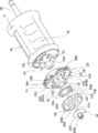
- FIG. 5 is an exploded perspective view showing the spool assembly in an exploded manner.
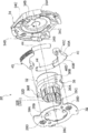
- FIG. 3 is an exploded perspective view showing a first clutch in an exploded manner.
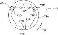
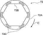
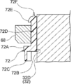
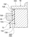
- FIG. 4 is an exploded perspective view showing the switching mechanism in an exploded manner. It is an expanded sectional view which expands and shows the end part of the axial direction one side of a spool. It is a top view showing a spacer. It is a side view which shows a spacer. It is a bottom view showing a spacer. It is a top view which shows the ratchet engaged with the ratchet engaging part of the guide part via the spacer.
- a webbing take-up device according to an embodiment of the present invention will be described with reference to FIGS. 1 to 8B.
- the webbing take-up device 10 of the present embodiment includes a frame 12, a spool 14, a webbing (not shown), a force limiter mechanism 16, a pretensioner mechanism 18, a first clutch 20, A switching mechanism 22, a pre-crash safety mechanism 24, and a winding attachment urging mechanism 26 are provided.
- the terms “axial direction”, “radial direction”, and “circumferential direction” indicate the rotational axis direction, the rotational radial direction, and the rotational circumferential direction of the spool unless otherwise specified.
- the frame 12 has a plate-shaped back plate 12A fixed to the vehicle body.
- Leg pieces 12B and 12C extend substantially at right angles from both ends in the width direction of the back plate 12A.
- a well-known lock mechanism and a pretensioner mechanism 18 are provided on the leg piece 12C side.
- a switching mechanism 22, a pre-crash safety mechanism 24, and a winding attachment mechanism 26 are provided on the leg piece 12B side.
- the spool 14 is formed in a cylindrical shape having a through hole 14A (see FIG. 2) penetrating in the axial direction, and is disposed between the leg piece 12B and the leg piece 12C of the frame 12.
- the spool 14 is rotatably supported by the frame 12 via a main torsion shaft 28, a sub torsion shaft 30, and the like, which will be described later.
- the webbing is mounted on the body of the occupant, and has a base end, which is one end in the longitudinal direction, locked to the spool 14.
- the spool 14 is rotationally urged in one winding direction (the direction of arrow C in FIG. 1 and the like) by the urging force of a mainspring spring (not shown) constituting a part of the winding attachment urging mechanism 26. .
- a mainspring spring constituting a part of the winding attachment urging mechanism 26.
- the webbing is wound on the spool 14 from the base end side.
- the spool 14 is rotated in the pulling-out direction (the direction opposite to the arrow C in FIG. 1 and the like) which is the other rotation direction.
- the force limiter mechanism 16 includes a main torsion shaft 28, a sub-torsion shaft 30, and the like.
- the main torsion shaft 28 is arranged coaxially with the spool 14.
- a part of the main torsion shaft 28 is fixed to a lock gear (not shown) constituting a part of a lock mechanism so as to be integrally rotatable with the lock gear.
- the other part of the main torsion shaft 28 is fixed to the spool 14 so as to be integrally rotatable while being arranged on the inner peripheral portion of the spool 14.
- the portion of the main torsion shaft 28 between the portion fixed to the lock gear and the portion fixed to the spool 14 is torsionally deformed so that the kinetic energy of the occupant used for pulling the webbing is absorbed. It has become.
- the sub-torsion shaft 30 is arranged coaxially with the main torsion shaft 28, and the base end side of the sub-torsion shaft 30 from the center in the longitudinal direction is inserted into the through hole 14A of the spool 14.
- the base end of the sub-torsion shaft 30 is fixed to the spool 14 so as to be able to rotate integrally with the spool 14.
- the distal end side of the sub-torsion shaft 30 from the longitudinal center portion protrudes from the spool 14 to the other axial side.
- a spline-shaped engaging portion 30A is formed at the tip of the sub-torsion shaft 30. Then, the portion between the engagement portion 30A and the portion fixed to the spool 14 in the sub-torsion shaft 30 is torsionally deformed, so that the kinetic energy of the occupant used for pulling the webbing is absorbed. ing.
- the first clutch 20 includes a sleeve 32, a clutch guide 34 as a guide, a clutch base 36, a clutch cover 38 as a cover, and a pair of clutch plates 40 as clutch pieces. , A screw 42 (see FIG. 2), and a pair of coil springs 44.
- the sleeve 32 is arranged coaxially with the sub-torsion shaft 30 (see FIG. 2).
- a through hole 32A penetrating in the axial direction is formed in the axial center of the sleeve 32, and the sub torsion shaft 30 is loosely inserted into the through hole 32A.
- a spline-shaped engaged portion 32B is formed on an inner peripheral portion of the sleeve 32, and an engaging portion 30A (see FIG. 2) of the sub-torsion shaft 30 is engaged with the engaged portion 32B. Have been. Thereby, the sleeve 32 is engaged with the sub-torsion shaft 30 so as to be integrally rotatable.
- the side of the sleeve 32 on the spool 14 side is a support portion 32C having a circular outer shape.
- the opposite side of the sleeve 32 from the spool 14 is a fitting portion as a ratchet engaging portion having a hexagonal outer shape. 32D.
- the clutch guide 34 is formed in an annular shape having a through hole 34A penetrating in the axial direction.
- the support portion 32C described above is inserted into the through hole 34A, whereby the clutch guide 34 is supported by the sleeve 32 so as to be relatively rotatable.
- a pair of coil spring housing portions 34B for housing the coil springs 44 are formed at two positions in the circumferential direction of the clutch guide 34.
- a pair of clutch plate housing portions 34C for housing the pair of clutch plates 40 are formed adjacent to the respective coil spring housing portions 34B.
- the clutch base 36 is formed integrally with the sleeve 32.
- the clutch base 36 includes an annular portion 36A protruding radially outward from the sleeve 32. Further, the clutch base 36 includes a pair of locking portions 36B protruding radially outward from the annular portion 36A. These locking portions 36B are locked to a base end of an arm portion 40A of the clutch plate 40 described later.
- the clutch cover 38 is disposed coaxially with the sleeve 32, is disposed on the opposite side of the clutch guide 34 from the spool 14, and is disposed to face the clutch guide 34.
- the clutch cover 38 is formed in an annular shape having a through hole 38A penetrating in the axial direction, and a plurality of fitting claws 38B protruding radially inward are formed on an inner peripheral portion thereof.
- the clutch cover 38 includes a spring locking portion 38C to which one end of the coil spring 44 is locked.
- the above-described clutch guide 34 is relatively rotatable with respect to the clutch cover 38 by the urging force of the coil spring 44 compressed between the spring locking portion 38C and the above-described clutch guide 34.
- the clutch plate 40 is disposed between the clutch cover 38 and the clutch guide 34.
- the clutch plate 40 has an arm portion 40A and an arc portion 40B formed at the tip of the arm portion 40A.
- a rotation shaft 40C that projects toward the clutch cover 38 and extends along the axial direction of the sub-torsion shaft 30 is formed.
- the clutch plate 40 is rotatably (tilted) supported by the clutch cover 38 by inserting the rotating shaft 40C into a hole 38D formed in the clutch cover 38. Further, flat teeth knurled teeth 40D are formed on the outer peripheral portion of the arc portion 40B (the tip portion of the clutch plate 40).
- the screw 42 includes a screw portion 42A, a winding attachment urging mechanism engaging portion 42B disposed coaxially with the screw portion 42A, and the screw portion 42A and the winding attaching urging mechanism engaging portion 42B. And a pressing portion 42C having a larger diameter than that of the pressing portion 42C.
- the screw 42A is fixed to the sub-torsion shaft 30 by being screwed to the tip of the sub-torsion shaft 30 (see FIG. 2).
- the winding attachment urging mechanism 26 (see FIG. 1) is engaged with the winding attachment urging mechanism engaging portion 42B. Thereby, the urging force of the mainspring spring forming a part of the winding attachment urging mechanism 26 is transmitted to the spool 14 via the screw 42 and the sub-torsion shaft 30.
- the clutch guide 34 has a hole 34D.
- a trigger wire 46 (see FIG. 2) is inserted into the hole 34D.
- the relative rotation of the clutch guide 34 with respect to the spool 14 and the clutch cover 38 is restricted (the clutch Guide 34 is constrained to the inoperative position).
- the switching mechanism 22 includes a case 48 formed in a box shape, a base cartridge 52 attached to the case 48 and supplied with gas generated by the gas generator 50, And a piston 54 that operates by receiving the pressure of the gas generated by 50.
- the switching mechanism 22 includes a pawl 56 whose arrangement is switched by being pressed by the piston 54, and a lock ring 58 as an engaged member whose rotation is regulated by the pawl 56.
- the pawl 56 is formed in a substantially plate shape, and includes a shaft portion 56A, and an arm portion 56B and an engaging portion 56C formed to extend radially outward of the shaft portion 56A. .
- the shaft 56A is rotatably supported by the case 48. Further, in a state where the engaging portion 56C is engaged with a notch portion 58B of the lock ring 58 described later, the arm portion 56B is arranged so as to be close to the piston 54.
- the lock ring 58 is formed in a substantially annular shape and is rotatably supported by the case 48.
- the lock ring 58 is disposed coaxially with the first clutch 20 on the outer peripheral side of the first clutch 20 (see FIG. 2).
- flat teeth knurl teeth 58A are formed on the inner peripheral portion of the lock ring 58.
- a cutout portion 58B having a substantially triangular cross section is formed on the outer peripheral portion of the lock ring 58, and the cutout portion 58B is opened radially outward of the lock ring 58.
- the pre-crash safety mechanism 24 includes a box-shaped case 60, a motor 62 attached to the case 60, and a motor 62 disposed in the case 60 and reducing the rotation of the motor 62. And a second clutch 66 (see FIG. 5) for transmitting the rotation of the motor 62 decelerated by the speed reducer 64 to the spool 14.
- the second clutch 66 includes a ratchet 68 engaged with the sleeve 32 of the first clutch 20 via a spacer 72 described later so as to be integrally rotatable with the sleeve 32, and a radial direction of the ratchet 68. And a ratchet engaging piece 70 as an engaging member provided on the outside. In FIG. 5, hatching of the cross section of each member is omitted.
- the ratchet 68 is formed in a disk shape arranged coaxially with the first clutch 20.
- a plurality of ratchet teeth 68A with which the ratchet engaging pieces 70 engage are formed on the outer peripheral portion of the ratchet 68.
- a fitting hole 68B having a hexagonal inner shape is formed in the center of the ratchet 68.
- three connection grooves 68C in which a connection portion 72D of the spacer 72 described later is disposed are formed along the axial direction.
- the three connection grooves 68C are arranged at regular intervals along the circumferential direction.
- the ratchet engagement piece 70 rotates around the ratchet 68 in the winding direction of the spool 14 when the rotation of the motor 62 is transmitted through the speed reducer 64. It is configured to be displaced to the ratchet 68 side. The rotational force of the motor 62 is transmitted to the ratchet 68 by engaging the ratchet engaging piece 70 displaced to the ratchet 68 with the ratchet teeth 68A of the ratchet 68.
- the rotational force transmitted to the ratchet 68 is transmitted to the spool 14 via the sleeve 32 and the sub-torsion shaft 30, so that the spool 14 is rotated in the winding direction, and the webbing is wound on the spool 14. It has become.
- the spacer 72 is formed using a resin material.
- the spacer 72 includes a first restricting portion 72A formed in a substantially disk shape.
- a fitting hole 72B having a hexagonal inner shape and into which the fitting portion 32D of the sleeve 32 is inserted is formed at the center of the first restriction portion 72A.
- the spacer 72 has six legs 72C protruding from the first restricting portion 72A toward the clutch base 36.
- the six legs 72C are arranged at equal intervals along the circumferential direction.
- the six legs 72C are arranged between the plurality of fitting claws 38B of the clutch cover 38, respectively.
- the tips of the six legs 72C abut on the clutch base 36.
- the spacer 72 has three connection portions 72D as interposition portions that protrude from the first restriction portion 72A in a direction opposite to the direction in which the leg portions 72C protrude. These three connection portions 72D are arranged at equal intervals along the circumferential direction.
- the thickness of the three connection portions 72D in the radial direction is set to a thickness that allows elastic deformation in the radial direction when the rotational force of the motor 62 is transmitted to the ratchet 68.
- the spacer 72 includes second restricting portions 72E that protrude radially outward from ends of the three connecting portions 72D opposite to the first restricting portion 72A.
- the axial dimension T from the second restricting portion 72E to the first restricting portion 72A is set to be slightly larger than the thickness dimension (dimension in the axial direction) of the ratchet 68.
- the end face of the second restriction part 72E on the side opposite to the first restriction part 72A is inclined radially inward toward the side opposite to the first restriction part 72A.
- the spacer 72 includes three crushing ribs 72F that protrude from ends of the three connecting portions 72D opposite to the first limiting portion 72A toward the opposite side to the first limiting portion 72A.
- the crushing rib 72F is formed in a conical shape that gradually narrows toward the opposite side to the first restricting portion 72A.
- the fitting portion 32D of the sleeve 32 is inserted into a fitting hole 72B formed at the center of the first restriction portion 72A of the spacer 72.
- the fitting portion 32D of the sleeve 32 is inserted into the fitting hole 68B formed at the center of the ratchet 68 together with the spacer 72.
- the connecting portion 72D of the spacer 72 is deformed radially inward.
- the portion of the spacer 72 including the second restriction portion 72E is reduced in diameter.
- a gap 74 is formed between the fitting part 32 ⁇ / b> D of the sleeve 32 and the ratchet 68 by the connecting part 72 ⁇ / b> D of the spacer 72.
- the webbing is pulled out from the spool 14 so that the webbing is attached to the body of the occupant of the vehicle.
- the control device determines whether there is a high possibility that the vehicle will collide, based on signals from various sensors provided in the vehicle. Then, when the control device determines that there is a high possibility that the vehicle will collide, the control device rotates the motor 62. When the rotational force of the motor 62 is transmitted to the ratchet engaging piece 70 (see FIG. 5), the ratchet engaging piece 70 is displaced toward the ratchet 68 and engages with the ratchet teeth 68A of the ratchet 68.
- the torque of the motor 62 is transmitted to the ratchet 68, and the torque transmitted to the ratchet 68 is transmitted to the spool 14 via the sleeve 32 and the sub-torsion shaft 30.
- the spool 14 is rotated in the winding direction, and the webbing is wound on the spool 14.
- the motor 62 is stopped, and the engagement between the ratchet engaging piece 70 and the ratchet teeth 68A of the ratchet 68 is released.
- the occupant's body pulls the webbing with a larger force, and the turning force of the spool 14 in the pulling-out direction based on this pulling force causes the main torsion shaft 28 to twist. If the load (deformation resistance load) is exceeded, the force limiter mechanism 16 is operated, and the torsion (deformation) of the main torsion shaft 28 allows the spool 14 to rotate in the pull-out direction at a force greater than the force limiter load.
- the spool 14 is rotated in the pulling-out direction by the torsion of the main torsion shaft 28, and the webbing is drawn from the spool 14, so that the load (burden) on the chest of the occupant due to the webbing is reduced. Further, the kinetic energy of the occupant used for pulling the webbing is absorbed by the twist of the main torsion shaft 28.
- control device determines whether or not the occupant's physique is equal to or greater than a predetermined reference value based on a signal from the physique detection means, and based on a signal from the collision detection means. It is determined whether or not has collided.
- the control device determines that the occupant's physique is equal to or larger than the predetermined reference value, the gas generator 50 of the switching mechanism 22 is not operated, and the engaging portion 56C of the pawl 56 It is engaged with the portion 58B. Therefore, the rotation of the lock ring 58 in the pull-out direction is locked (prevented), so that the rotation of the first clutch 20 in the pull-out direction is blocked.
- the load (load) on the occupant's chest due to the webbing is reduced by rotating the spool 14 in the pulling-out direction and pulling out the webbing from the spool 14 due to the twist of the main torsion shaft 28 and the sub-torsion shaft 30.
- the kinetic energy of the occupant used for pulling the webbing is absorbed by the torsion of the main torsion shaft 28 and the sub torsion shaft 30.
- the control device determines that the occupant's physique is less than a predetermined reference value based on the signal from the physique detection means, and determines that the vehicle has collided based on the signal of the collision detection means.
- the gas generator 50 is operated under the control of the control device.
- the piston 54 presses the arm portion 56B of the pawl 56 by the movement of the piston 54.
- the pawl 56 rotates about the shaft 56A, and the engagement between the engaging portion 56C of the pawl 56 and the notch 58B of the lock ring 58 is released.
- the rotation of the lock ring 58 in the pulling-out direction is allowed, and the first clutch 20 and the sub-torsion shaft 30 are allowed to rotate in the pulling-out direction together with the spool 14. Therefore, the torsion of the sub-torsion shaft 30 does not occur, and the torsion (deformation) of the main torsion shaft 28 causes the rotation of the spool 14 in the pull-out direction at a force limiter load (the torsional load of the main torsion shaft 28) or more. Permissible.
- the rotation of the sub-torsion shaft 30 in the pull-out direction is not allowed by the operation of the switching mechanism 22, so that the force limiter load is reduced by the torsion resistance of the main torsion shaft 28.
- the load value of the force limiter load is set to a high load by summing the load and the torsional load of the sub-torsion shaft 30.
- the rotation of the sub-torsion shaft 30 in the pulling-out direction is allowed by the operation of the switching mechanism 22, and the force limiter load is reduced.
- the load value of the force limiter load is adjusted according to the physique of the occupant, and the load (burden) on the occupant's chest due to the webbing can be reduced to appropriately protect the occupant.
- the ratchet 68 is engaged with the sleeve 32 of the first clutch 20 via the spacer 72.
- the clearance between the ratchet 68 and the clutch cover 38 of the first clutch 20 is ensured by the leg 72C of the spacer 72, and the movement of the ratchet 68 toward the clutch cover 38 is restricted by the first restriction of the spacer 72.
- Portion 72A Accordingly, it is possible to suppress the influence on the operation of the first clutch 20 due to the interference of the ratchet 68 with the clutch cover 38 and the clutch plate 40 (the rotation shaft 40C).
- the movement of the ratchet 68 to the side opposite to the clutch cover 38 is restricted by the second restricting portion 72E of the spacer 72. Accordingly, it is possible to prevent the ratchet 68 from coming off the spacer 72, that is, to prevent the spacer 72 from coming off from the ratchet 68.
- the fitting portion 32D of the sleeve 32 is connected by the connecting portion 72D of the spacer 72.
- a gap 74 is formed between the armature and the ratchet 68.
- the connecting portion 72D of the spacer 72 has a diameter. Deforms inward in the direction. Thereby, the ratchet 68 comes into contact with the fitting portion 32 ⁇ / b> D of the sleeve 32. Thereby, the rotational force of the ratchet 68 can be transmitted directly to the sleeve 32. As a result, it is not necessary to give the spacer 72 a strength corresponding to the rotational force of the ratchet 68, and the weight of the spacer 72 can be reduced.
- the present invention is not limited to this. That is, the contact of the ratchet 68 with a portion of the first clutch 20 that may hinder the operation of the first clutch 20 may be suppressed by the spacer 72.
- the first clutch 20 to which the rotational force of the spool 14 is transmitted by operating the switching mechanism 22 and the rotational force to the spool 14 by operating the pre-crash safety mechanism 24 is not limited to this.
- a spacer may be provided between one clutch in which the rotational force is transmitted to the spool 14 when activated, and another clutch in which the rotational force of the spool 14 is transmitted when activated.
Landscapes
- Engineering & Computer Science (AREA)
- Mechanical Engineering (AREA)
- Automation & Control Theory (AREA)
- Automotive Seat Belt Assembly (AREA)
Abstract
ウェビング巻取装置は、ウェビングが巻取られるスプールと、作動されることで、スプールへ回転力を伝達させる、或いは、スプールからの回転力を伝達させる第1クラッチと、前記第1クラッチと隣合って配置され、作動されることで、スプールへ回転力を伝達させる、或いは、スプールからの回転力を伝達させる第2クラッチと、前記第1クラッチと前記第2クラッチとの間に設けられ、前記第1クラッチ及び前記第2クラッチの一方の干渉による前記第1クラッチ及び前記第2クラッチの他方の作動への影響を抑制するスペーサと、を備える。
Description
本発明は、ウェビング巻取装置に関する。
特開2010-208639号公報及び特開2014-125183号公報には、モータの回転力がスプールに伝達されることで、乗員に装着されるウェビングがスプールに巻取られるウェビング巻取装置が開示されている。このウェビング巻取装置は、モータの回転力をスプール伝達させるクラッチを備えており、このクラッチが作動することで、モータの回転力がスプールに伝達されるようになっている。
ところで、スプールへの回転力を断接させる、或いは、スプールからの回転力を断接させる複数のクラッチを有する構成では、一方のクラッチの作動が他方のクラッチによって妨げられないようにすることが重要である。
本発明は上記事実を考慮し、一方のクラッチの作動が他方のクラッチによって妨げられることを抑制することができるウェビング巻取装置を得ることが目的である。
第1の態様に係るウェビング巻取装置は、乗員に装着されるウェビングが巻取られるスプールと、作動されることで、スプールへ回転力を伝達させる、或いは、スプールからの回転力を伝達させる第1クラッチと、前記第1クラッチと隣合って配置され、作動されることで、スプールへ回転力を伝達させる、或いは、スプールからの回転力を伝達させる第2クラッチと、前記第1クラッチと前記第2クラッチとの間に設けられ、前記第1クラッチ及び前記第2クラッチの一方の干渉による前記第1クラッチ及び前記第2クラッチの他方の作動への影響を抑制するスペーサと、を備えている。
第2の態様に係るウェビング巻取装置は、第1の態様のウェビング巻取装置において、前記スプールは、巻取方向へ回転されることで前記ウェビングが巻取られ、前記ウェビングが引出されることで引出方向へ回転され、前記スプールのフォースリミッタ荷重以上での引出方向への回転を許容するフォースリミッタ機構をさらに備え、前記第1クラッチは、前記スプールと一体回転可能に設けられ、作動されると共にその回転径方向外側に設けられた被係合部材に係合されて前記フォースリミッタ荷重が切替可能とされ、前記第2クラッチは、前記スペーサを介して前記第1クラッチに係合されることで前記第1クラッチと一体回転可能とされたラチェットと、前記ラチェットの回転径方向外側に設けられた係合部材と、を含んで構成され、前記係合部材が前記ラチェットに係合されることで、前記ラチェットへ前記スプールの巻取方向への回転力が伝達される。
第3の態様に係るウェビング巻取装置は、第2の態様のウェビング巻取装置において、前記第1クラッチは、回転径方向外側へ変位されることで前記被係合部材に係合されるクラッチ片と、前記クラッチ片の前記ラチェット側を覆うカバー部と、を含んで構成され、前記スペーサは、前記ラチェットの前記カバー部側への移動を制限する第1制限部を備えている。
第4の態様に係るウェビング巻取装置は、第3の態様のウェビング巻取装置において、前記スペーサは、前記ラチェットの前記カバー部とは反対側への移動を制限する第2制限部を備えている。
第5の態様に係るウェビング巻取装置は、第1の態様~第4の態様のいずれかのウェビング巻取装置において、前記第1クラッチは、前記ラチェットが前記スペーサを介して係合されるラチェット係合部を備え、前記スペーサは、前記ラチェット係合部と前記ラチェットとの間に介在される介在部を備え、前記係合部材が前記ラチェットに係合される前の状態では、前記介在部によって前記ラチェット係合部と前記ラチェットとの間に隙間が形成され、前記係合部材が前記ラチェットに係合されて該ラチェットが回転される際に、前記介在部が変形して、前記ラチェットと前記ラチェット係合部とが接触する。
第1の態様に係るウェビング巻取装置では、乗員に装着されるウェビングがスプールに巻取られる。そして、第1クラッチが作動されると、スプールへ回転力が伝達される、或いは、スプールからの回転力が伝達される。また、第2クラッチが作動されると、スプールへ回転力が伝達される、或いは、スプールからの回転力が伝達される。ここで、第1クラッチと第2クラッチとの間には、スペーサが設けられている。このスペーサを有することにより、第1クラッチ及び第2クラッチの一方の干渉による第1クラッチ及び第2クラッチの他方の作動への影響が抑制される。
第2の態様に係るウェビング巻取装置は、フォースリミッタ機構を備えている。このフォースリミッタ機構によって、スプールのフォースリミッタ荷重以上での引出方向への回転が許容される。そして、第1クラッチが作動されて、第1クラッチが被係合部材に係合されると、フォースリミッタ荷重が切替可能とされる。また、係合部材がラチェットに係合されることで、ラチェットへスプールの巻取方向への回転力が伝達される。これにより、ラチェットの回転力が第1クラッチを介してスプールに伝達されて、スプールが巻取方向へ回転される。ここで、ラチェットは、スペーサを介して第1クラッチに係合される。これにより、ラチェットが第1クラッチに干渉することによる第1クラッチの作動への影響が抑制される。
第3の態様に係るウェビング巻取装置では、第1クラッチのクラッチ片が回転径方向外側へ変位して被係合部材に係合されると、フォースリミッタ荷重が切替可能とされる。また、係合部材がラチェットに係合されることで、ラチェットへスプールの巻取方向への回転力が伝達される。これにより、ラチェットの回転力が第1クラッチのラチェット係合部を介してスプールに伝達されて、スプールが巻取方向へ回転される。ここで、第1クラッチのカバー部がクラッチ片のラチェット側を覆う。そして、ラチェットの第1クラッチのカバー部側への移動が、スペーサの第1制限部によって制限される。これにより、ラチェットが第1クラッチのカバー部やクラッチ片に干渉することによる第1クラッチの作動への影響が抑制される。
第4の態様に係るウェビング巻取装置では、ラチェットのカバー部とは反対側への移動がスペーサの第2制限部によって制限されている。これにより、ラチェットがスペーサから外れることを抑制することができる。
第5の態様に係るウェビング巻取装置では、係合部材がラチェットに係合される前の状態では、スペーサの介在部によってラチェット係合部とラチェットとの間に隙間が形成される。これにより、ラチェット係合部とラチェットとが接触することによる異音の発生が抑制される。また、係合部材がラチェットに係合されてラチェットが回転される際に、スペーサの介在部が変形して、ラチェットとラチェット係合部とが接触する。これにより、ラチェットの回転力をラチェット係合部にダイレクトに伝達させることができる。その結果、ラチェットの回転力に対応する強度をスペーサに持たせることが不要となり、スペーサの軽量化を図ることができる。
図1~図8Bを用いて、本発明の実施形態に係るウェビング巻取装置について説明する。
図1に示されるように、本実施形態のウェビング巻取装置10は、フレーム12と、スプール14と、図示しないウェビングと、フォースリミッタ機構16と、プリテンショナ機構18と、第1クラッチ20と、切替機構22と、プリクラッシュセーフティー機構24と、巻取付勢機構26と、を備えている。なお、以下、単に軸方向、径方向、周方向を示す場合は、特に断りのない限り、スプールの回転軸方向、回転径方向、回転周方向を示すものとする。
フレーム12は、車体に固定される板状の背板12Aを備えている。また、背板12Aの幅方向両端部からは脚片12B,12Cが略直角に延出されている。脚片12C側には、周知のロック機構及びプリテンショナ機構18が設けられている。また、脚片12B側には、切替機構22、プリクラッシュセーフティー機構24及び巻取付勢機構26が設けられている。
スプール14は、軸方向に貫通する貫通孔14A(図2参照)を有する円筒状に形成されており、フレーム12の脚片12Bと脚片12Cとの間に配置されている。スプール14は、後述するメイントーションシャフト28、サブトーションシャフト30等を介してフレーム12に回転可能に支持されている。
ウェビングは、乗員の身体に装着されるものであり、その長手方向一端部である基端部がスプール14に係止されている。スプール14は、巻取付勢機構26の一部を構成する図示しないゼンマイばねの付勢力によって、一方の回転方向である巻取方向(図1等の矢印Cの方向)へ回転付勢されている。そして、スプール14が、巻取方向へ回転されることで、ウェビングが基端側からスプール14に巻取られるようになっている。また、ウェビングがスプール14から引出されることで、スプール14が他方の回転方向である引出方向(図1等の矢印Cとは反対の方向)へ回転されるようになっている。
図2に示されるように、フォースリミッタ機構16は、メイントーションシャフト28及びサブトーションシャフト30等を含んで構成されている。
メイントーションシャフト28は、スプール14と同軸上に配置されている。このメイントーションシャフト28の一部は、ロック機構の一部を構成する図示しないロックギヤに当該ロックギヤと一体回転可能に固定されている。また、メイントーションシャフト28の他の一部は、スプール14の内周部に配置された状態で、当該スプール14と一体回転可能に固定されている。そして、メイントーションシャフト28においてロックギヤに固定された部分とスプール14に固定された部分との間の部分がねじれ変形されることで、ウェビングの引張りに供される乗員の運動エネルギが吸収されるようになっている。
サブトーションシャフト30は、メイントーションシャフト28と同軸上に配置されており、その長手方向中央部よりも基端側は、スプール14の貫通孔14Aに挿入されている。また、サブトーションシャフト30の基端部は、スプール14に当該スプール14と一体回転可能に固定されている。一方、このサブトーションシャフト30の長手方向中央部よりも先端側は、スプール14から軸方向他方側に突出されている。また、サブトーションシャフト30の先端部には、スプライン状の係合部30Aが形成されている。そして、サブトーションシャフト30において係合部30Aとスプール14に固定された部分との間の部分がねじれ変形されることで、ウェビングの引張りに供される乗員の運動エネルギが吸収されるようになっている。
図3に示されるように、第1クラッチ20は、スリーブ32と、ガイド部としてのクラッチガイド34と、クラッチベース36と、カバー部としてのクラッチカバー38と、クラッチ片としての一対のクラッチプレート40と、スクリュ42(図2参照)と、一対のコイルスプリング44と、を備えている。
スリーブ32は、サブトーションシャフト30(図2参照)と同軸上に配置されている。このスリーブ32の軸心部には、軸方向に貫通する貫通孔32Aが形成されており、この貫通孔32Aには、サブトーションシャフト30が遊挿されている。また、このスリーブ32の内周部には、スプライン状の被係合部32Bが形成されており、この被係合部32Bにサブトーションシャフト30の係合部30A(図2参照)が係合されている。これにより、スリーブ32は、サブトーションシャフト30に一体回転可能に係合されている。また、スリーブ32におけるスプール14側は、円形状の外形を有する支持部32Cとされており、スリーブ32におけるスプール14とは反対側は、六角形状の外形を有するラチェット係合部としての嵌合部32Dとされている。
クラッチガイド34は、軸方向に貫通する貫通孔34Aを有する環状に形成されている。この貫通孔34Aには、上述の支持部32Cが挿入されており、これにより、クラッチガイド34は、スリーブ32に相対回転可能に支持されている。このクラッチガイド34における周方向の二箇所の位置には、コイルスプリング44を収容する一対のコイルスプリング収容部34Bが形成されている。また、このクラッチガイド34には、一対のクラッチプレート40を収容する一対のクラッチプレート収容部34Cが各コイルスプリング収容部34Bに隣接して形成されている。
クラッチベース36は、スリーブ32と一体に形成されている。このクラッチベース36は、スリーブ32から径方向外側へ向けて突出する環状部36Aを備えている。また、クラッチベース36は、環状部36Aから径方向外側に突出する一対の係止部36Bを備えている。これらの係止部36Bは、後述するクラッチプレート40のアーム部40Aの基端部に係止されている。
クラッチカバー38は、スリーブ32と同軸上に配置されると共に、クラッチガイド34に対してスプール14とは反対側に配置され、かつクラッチガイド34と対向して配置されている。このクラッチカバー38は、軸方向に貫通する貫通孔38Aを有する環状に形成されており、その内周部には、径方向内側に突出する嵌合爪38Bが複数形成されている。そして、貫通孔38Aにスリーブ32の嵌合部32Dが挿入されると共に、複数の嵌合爪38Bが嵌合部32Dと嵌合されることにより、クラッチカバー38は、スリーブ32、ひいては、サブトーションシャフト30に一体回転可能に係合されている。また、クラッチカバー38は、コイルスプリング44の一方側の端部が係止されるスプリング係止部38Cを備えている。このスプリング係止部38Cと前述のクラッチガイド34との間で圧縮されたコイルスプリング44の付勢力によって、前述のクラッチガイド34は、クラッチカバー38に対して相対回転可能となっている。
クラッチプレート40は、クラッチカバー38とクラッチガイド34との間に配置されている。このクラッチプレート40は、アーム部40Aと、このアーム部40Aの先端部に形成された円弧部40Bと、を有している。アーム部40Aの基端部には、クラッチカバー38側に突出すると共にサブトーションシャフト30の軸方向に沿って延びる回動軸40Cが形成されている。そして、この回動軸40Cがクラッチカバー38に形成された孔部38Dに挿入されることにより、クラッチプレート40は、クラッチカバー38に回動(傾動)可能に支持されている。また、円弧部40Bの外周部(クラッチプレート40の先端部)には、平歯状のローレット歯40Dが形成されている。
図2に示されるように、スクリュ42は、ネジ部42Aと、ネジ部42Aと同軸上に配置された巻取付勢機構係合部42Bと、このネジ部42A及び巻取付勢機構係合部42Bよりも大径の押え部42Cと、を有して構成されている。ネジ部42Aがサブトーションシャフト30(図2参照)の先端部に螺合されることで、スクリュ42がサブトーションシャフト30に固定されている。巻取付勢機構係合部42Bには、巻取付勢機構26(図1参照)が係合されている。これにより、巻取付勢機構26の一部を構成するゼンマイばねの付勢力が、スクリュ42及びサブトーションシャフト30を介してスプール14に伝達されるようになっている。
図3に示されるように、前述のクラッチガイド34には、孔部34Dが形成されている。この孔部34Dには、トリガワイヤ46(図2参照)が挿入されている。トリガワイヤ46が孔部34Dに挿入された状態でかつトリガワイヤ46の一部がクラッチカバー38に当接した状態では、クラッチガイド34は、スプール14及びクラッチカバー38に対する相対回転を制限されている(クラッチガイド34が非作動位置に拘束されている)。
また、前述のように、クラッチガイド34が非作動位置に拘束された状態では、コイルスプリング44が圧縮されている。これにより、クラッチガイド34は作動位置へと回転付勢されている。さらに、この状態では、クラッチプレート40は、ローレット歯40Dがクラッチガイド34の外周部よりも内側に納まるように、クラッチプレート収容部34Cに収容される。
図4に示されるように、切替機構22は、箱状に形成されたケース48と、このケース48に取付けられると共にガスジェネレータ50が発生したガスが内部に供給されるベースカートリッジ52と、ガスジェネレータ50によって発生したガスの圧力を受けて作動するピストン54と、を備えている。また、切替機構22は、ピストン54に押圧されることによって配置の切替えがなされるパウル56と、このパウル56によって回転が規制される被係合部材としてのロックリング58と、を備えている。
パウル56は、略板状に形成されていると共に、軸部56Aと、この軸部56Aの径方向外側へ延出するように形成されたアーム部56B及び係合部56Cと、を備えている。また、軸部56Aは、ケース48に回動自在に支持されている。さらに、係合部56Cが後述するロックリング58の切欠部58Bに係合した状態では、アーム部56Bはピストン54と近接するように配置されている。
ロックリング58は、略円環状に形成されていると共に、ケース48に回転自在に支持されている。また、ロックリング58は、第1クラッチ20(図2参照)の外周側において、第1クラッチ20と同軸上に配置されている。また、ロックリング58の内周部には、平歯状のローレット歯58Aが形成されている。さらに、ロックリング58の外周部には、断面略三角形状の切欠部58Bが形成されており、この切欠部58Bはロックリング58の径方向外側へ開口されている。
図1に示されるように、プリクラッシュセーフティー機構24は、箱状に形成されたケース60と、ケース60に取付けられたモータ62と、ケース60内に配置されていると共にモータ62の回転を減速する減速機64と、減速機64で減速されたモータ62の回転をスプール14に伝達させる第2クラッチ66(図5参照)と、を備えている。
図5に示されるように、第2クラッチ66は、第1クラッチ20のスリーブ32に後述するスペーサ72を介して当該スリーブ32と一体回転可能に係合されたラチェット68と、ラチェット68の径方向外側に設けられた係合部材としてのラチェット係合片70と、を含んで構成されている。なお、図5においては、各部材の断面のハッチングを省略している。
図2及び図5に示されるように、ラチェット68は、第1クラッチ20と同軸上に配置された円板状に形成されている。このラチェット68の外周部には、ラチェット係合片70が係合する複数のラチェット歯68Aが形成されている。また、ラチェット68の中心部には、六角形状の内形を有する嵌合孔68Bが形成されている。また、嵌合孔68Bの内周部には、後述するスペーサ72の接続部72Dがその内部に配置される3つの接続溝68Cが軸方向に沿って形成されている。また、3つの接続溝68Cは周方向に沿って等間隔に配置されている。
図1及び図5に示されるように、ラチェット係合片70は、モータ62の回転が減速機64を介して伝達されることで、ラチェット68の周りをスプール14の巻取方向へ回転すると共にラチェット68側へ変位するように構成されている。そして、ラチェット68側へ変位したラチェット係合片70が、ラチェット68のラチェット歯68Aに係合することで、モータ62の回転力がラチェット68に伝達される。また、ラチェット68に伝達された回転力が、スリーブ32及びサブトーションシャフト30を介してスプール14に伝達されることで、スプール14が巻取方向へ回転されて、ウェビングがスプール14に巻取られるようになっている。
次に、スペーサ72の構成について説明する。
図5及び図6A~図6Cに示されるように、スペーサ72は、樹脂材料を用いて形成されている。このスペーサ72は、略円板状に形成された第1制限部72Aを備えている。この第1制限部72Aの中心部には、六角形状の内形を有すると共にスリーブ32の嵌合部32Dが挿入される嵌合孔72Bが形成されている。
また、スペーサ72は、第1制限部72Aからクラッチベース36側へ向けて突出する6つの脚部72Cを備えている。この6つの脚部72Cは、周方向に沿って等間隔に配置されている。また、スリーブ32の嵌合部32Dが第1制限部72Aの嵌合孔72Bに挿入された状態では、6つの脚部72Cはクラッチカバー38の複数の嵌合爪38Bの間にそれぞれ配置されると共に、6つの脚部72Cのそれぞれの先端がクラッチベース36に当接するようになっている。
また、スペーサ72は、第1制限部72Aから脚部72Cが突出する方向とは反対側へ向けて突出する介在部としての3つの接続部72Dを備えている。この3つの接続部72Dは、周方向に沿って等間隔に配置されている。また、3つの接続部72Dの径方向への厚みは、モータ62の回転力がラチェット68へ伝達された際に径方向へ弾性変形可能な厚みに設定されている。
また、スペーサ72は、3つの接続部72Dにおける第1制限部72Aとは反対側の端部から径方向外側へ向けてそれぞれ突出する第2制限部72Eを備えている。この第2制限部72Eから第1制限部72Aまでの軸方向への寸法Tは、ラチェット68の厚み寸法(軸方向への寸法)よりもやや大きな寸法に設定されている。また、第2制限部72Eにおける第1制限部72Aとは反対側の端面は、第1制限部72Aとは反対側に向かうにつれて径方向内側へ傾斜している。
また、スペーサ72は、3つの接続部72Dにおける第1制限部72Aとは反対側の端部から当該第1制限部72Aとは反対側へ向けてそれぞれ突出する3つの潰しリブ72Fを備えている。この潰しリブ72Fは、第1制限部72Aとは反対側へ向かうにつれて次第に窄まる円錐形状に形成されている。
次に、ラチェット68を第1クラッチ20のスリーブ32にスペーサ72を介して係合させる手順について説明する。
図5に示されるように、先ず、スペーサ72の第1制限部72Aの中心部に形成された嵌合孔72Bにスリーブ32の嵌合部32Dを挿入する。次に、ラチェット68の中心部に形成された嵌合孔68Bに、スリーブ32の嵌合部32Dをスペーサ72と共に挿入する。この時、スペーサ72の第2制限部72Eが、ラチェット68の嵌合孔68Bの内周面に押圧されることで、スペーサ72の接続部72Dが径方向内側へ変形する。これにより、スペーサ72において第2制限部72Eを含む部分が縮径される。その結果、スリーブ32の嵌合部32D及びスペーサ72のラチェット68の嵌合孔68Bへの挿入が、スペーサ72の第2制限部72Eによって妨げられることが抑制されている。また、スリーブ32の嵌合部32D及びスペーサ72のラチェット68の嵌合孔68Bへの挿入が完了すると、スペーサ72の接続部72Dが径方向外側へ復元する。これにより、スペーサ72において第2制限部72Eを含む部分が拡径される。この状態では、図7に示されるように、スペーサ72の第2制限部72Eとラチェット68の嵌合孔68Bの縁部とが軸方向にオーバーラップする。また、ラチェット係合片70がラチェット68に係合される前の状態では、スペーサ72の接続部72Dによってスリーブ32の嵌合部32Dとラチェット68との間に隙間74が形成されている。
次に、図5に示されるように、スクリュ42のネジ部42Aをサブトーションシャフト30の先端部に螺合させる。これにより、ラチェット68がスペーサ72と共にスクリュ42の押え部42Cとクラッチベース36との間に配置される。以上の手順を経て、ラチェット68が第1クラッチ20のスリーブ32にスペーサ72を介して係合される。
ここで、本実施形態では、図8A及び図8Bに示されるように、スクリュ42のネジ部42Aをサブトーションシャフト30の先端部に螺合させる際に、スペーサ72の潰しリブ72Fが塑性変形される(潰される)。これにより、スペーサ72がスクリュ42の押え部42Cとクラッチベース36との間でがたつくことが抑制されている。
(本実施形態の作用並びに効果)
次に、本実施形態の作用並びに効果について説明する。
次に、本実施形態の作用並びに効果について説明する。
図1及び図2に示されるように、本実施形態に係るウェビング巻取装置10では、ウェビングがスプール14から引出されることで、ウェビングが車両の乗員の身体に装着される。
ここで、図示しない制御装置は、車両に設けられた各種センサからの信号に基づいて、車両が衝突する可能性が高いか否かを判断する。そして、制御装置が、車両が衝突する可能性が高いと判断すると、制御装置はモータ62を回転させる。モータ62の回転力が、ラチェット係合片70(図5参照)に伝達されると、ラチェット係合片70がラチェット68側へ変位して当該ラチェット68のラチェット歯68Aに係合する。これにより、モータ62の回転力がラチェット68に伝達され、ラチェット68に伝達された回転力が、スリーブ32及びサブトーションシャフト30を介してスプール14に伝達される。その結果、スプール14が巻取方向へ回転されて、ウェビングがスプール14に巻取られる。これにより、車両の衝突前に、ウェビングの弛みを取除くことができる。なお、ウェビングの弛みが取除かれると、モータ62が停止されて、ラチェット係合片70とラチェット68のラチェット歯68Aとの係合が外れる。
また、ウェビングが車両の乗員の身体に装着された状態で、例えば、車両が急減速状態になり、ロック機構が作動すると、ロックギヤの引出方向への回転が阻止される。その結果、このロックギヤにメイントーションシャフト28を介して連結されたスプール14の引出方向への回転が制限されて、スプール14からのウェビングの引出しが制限される。したがって、車両前方へ移動しようとする乗員の身体がウェビングによって拘束される。
また、ロックギヤの引出方向への回転が阻止された状態で、更に大きな力で乗員の身体がウェビングを引張り、この引張力に基づく引出方向へのスプール14の回転力がメイントーションシャフト28の耐捩れ荷重(耐変形荷重)を上回ると、フォースリミッタ機構16が作動されて、メイントーションシャフト28の捩れ(変形)により、スプール14のフォースリミッタ荷重以上での引出方向への回転が許容される。
したがって、メイントーションシャフト28の捩れによりスプール14が引出方向へ回転されてスプール14からウェビングが引出されることで、ウェビングによる乗員の胸部への負荷(負担)が軽減される。またメイントーションシャフト28の捩れ分だけウェビングの引張りに供される乗員の運動エネルギが吸収される。
一方、上述のように、ロックギヤに対してスプール14が引出方向に回転されると、トリガワイヤ46が引っ張られる。これにより、トリガワイヤ46の先端部が、図3に示されたクラッチガイド34の孔部34Dから引抜かれて、スプール14及びクラッチカバー38に対するクラッチガイド34の相対回転の阻止状態が解消される。
そして、図3及び図4に示されるように、コイルスプリング44の付勢力により、クラッチガイド34が非作動位置から作動位置へと回転されると、クラッチプレート40がクラッチプレート収容部から径方向外側のロックリング58側へ回動され、クラッチプレート40のローレット歯40Dがロックリング58のローレット歯58Aと噛合う。これにより、第1クラッチ20の引出方向への回転と一体に、ロックリング58が引出方向へ回転しようとする(スプール14の回転力が第1クラッチ20を介してロックリング58に伝達される)。
また、図示しない制御装置は、体格検出手段からの信号に基づいて、乗員の体格が予め定められた基準値以上であるか否かを判定すると共に、衝突検出手段からの信号に基づいて、車両が衝突したか否かを判定している。そして、制御装置が、乗員の体格が予め定められた基準値以上であると判定した場合では、切替機構22のガスジェネレータ50が作動されないため、パウル56の係合部56Cがロックリング58の切欠部58Bに係合している。このため、ロックリング58の引出方向への回転がロック(阻止)されることで、第1クラッチ20の引出方向への回転が阻止される。
そして、第1クラッチ20のスリーブ32の引出方向への回転が阻止された状態で、更に大きな力で乗員の身体がウェビングを引張り、この引張力に基づく引出方向へのスプール14の回転力がメイントーションシャフト28の耐捩れ荷重(耐変形荷重)とサブトーションシャフト30の耐捩れ荷重(耐変形荷重)との合計を上回ると、両者の捩れ(変形)により、スプール14のフォースリミッタ荷重(メイントーションシャフト28の耐捩れ荷重とサブトーションシャフト30の耐捩れ荷重との合計)以上でのスプール14の引出方向への回転が許容される。
したがって、メイントーションシャフト28及びサブトーションシャフト30の捩れによりスプール14が引出方向へ回転されてスプール14からウェビングが引出されることで、ウェビングによる乗員の胸部への負荷(負担)が軽減されると共に、メイントーションシャフト28及びサブトーションシャフト30の捩れ分だけウェビングの引張りに供される乗員の運動エネルギが吸収される。
一方、制御装置が、体格検出手段からの信号に基づいて、乗員の体格が予め定められた基準値未満であると判定すると共に、衝突検出手段の信号に基づいて、車両が衝突したと判定した場合には、制御装置の制御によりガスジェネレータ50が作動される。これにより、ピストン54が移動することによって、ピストン54がパウル56のアーム部56Bを押圧する。その結果、パウル56が軸部56Aを軸中心として回転すると共に、パウル56の係合部56Cとロックリング58の切欠部58Bとの係合が外れる。これにより、ロックリング58の引出方向への回転が許容されて、第1クラッチ20及びサブトーションシャフト30がスプール14と共に引出方向へ回転可能にされる。このため、サブトーションシャフト30に捩れは生じないため、メイントーションシャフト28の捩れ(変形)により、スプール14のフォースリミッタ荷重(メイントーションシャフト28の耐捩れ荷重)以上での引出方向への回転が許容される。
すなわち、乗員の体格が予め定められた基準値以上である場合では、切替機構22の作用によってサブトーションシャフト30の引き出し方向への回転が許容されないので、フォースリミッタ荷重がメイントーションシャフト28の耐捩れ荷重及びサブトーションシャフト30の耐捩れ荷重との合計にされて、フォースリミッタ荷重の荷重値が高荷重にされる。一方、乗員の体格が予め定められた基準値未満であり、車両の衝突が検出された場合には、切替機構22の作用によってサブトーションシャフト30の引き出し方向への回転が許容され、フォースリミッタ荷重がメイントーションシャフト28の耐捩れ荷重にされて、フォースリミッタ荷重の荷重値が低荷重にされる。このため、乗員を体格に応じてフォースリミッタ荷重の荷重値を調整し、ウェビングによる乗員の胸部への負荷(負担)を軽減して乗員を適切に保護することができる。
ここで、図5に示されるように、本実施形態では、ラチェット68が第1クラッチ20のスリーブ32にスペーサ72を介して係合される。そして、ラチェット68と第1クラッチ20のクラッチカバー38との間のクリアランスが、スペーサ72の脚部72Cによって確保されると共に、ラチェット68のクラッチカバー38側への移動が、スペーサ72の第1制限部72Aによって制限される。これにより、ラチェット68がクラッチカバー38やクラッチプレート40(回動軸40C)に干渉することによる第1クラッチ20の作動への影響を抑制することができる。
また、本実施形態では、ラチェット68のクラッチカバー38とは反対側への移動がスペーサ72の第2制限部72Eによって制限されている。これにより、ラチェット68がスペーサ72から外れる、すなわちスペーサ72がラチェット68から外れることを抑制することができる。
さらに、本実施形態では、図5及び図7に示されるように、ラチェット係合片70がラチェット68に係合される前の状態では、スペーサ72の接続部72Dによってスリーブ32の嵌合部32Dとラチェット68との間に隙間74が形成されている。これにより、スリーブ32の嵌合部32Dとラチェット68とが接触することによる異音の発生を抑制することができる。
また、モータ62(図1参照)の回転力がラチェット係合片70を介してラチェット68に伝達されて、当該ラチェット68が巻取方向へ回転される際に、スペーサ72の接続部72Dが径方向内側等に変形する。これにより、ラチェット68がスリーブ32の嵌合部32Dに接触する。これにより、ラチェット68の回転力をスリーブ32にダイレクトに伝達させることができる。その結果、ラチェット68の回転力に対応する強度をスペーサ72に持たせることが不要となり、スペーサ72の軽量化を図ることができる。
なお、本実施形態では、ラチェット68が第1クラッチ20のクラッチカバー38やクラッチプレート40に接触することをスペーサ72によって抑制した例について説明したが、本発明はこれに限定されない。すなわち、第1クラッチ20において当該第1クラッチ20の作動を妨げる虞がある部位へのラチェット68の接触が、スペーサ72によって抑制されていればよい。
また、本実施形態では、切替機構22が作動されることでスプール14の回転力が伝達される第1クラッチ20と、プリクラッシュセーフティー機構24が作動されることでスプール14へ回転力が伝達される第2クラッチ66との間にスペーサ72を設けた例について説明したが、本発明はこれに限定されない。
例えば、作動されることでスプール14へ回転力が伝達される一のクラッチと、作動されることでスプール14の回転力が伝達される別のクラッチとの間にスペーサを設けてもよい。
日本出願2018-149132の開示はその全体が参照により本明細書に取り込まれる。
本明細書に記載された全ての文献、特許出願、及び技術規格は、個々の文献、特許出願、及び技術規格が参照により取り込まれることが具体的にかつ個々に記載された場合と同様に、本明細書中に参照により取り込まれる。
本明細書に記載された全ての文献、特許出願、及び技術規格は、個々の文献、特許出願、及び技術規格が参照により取り込まれることが具体的にかつ個々に記載された場合と同様に、本明細書中に参照により取り込まれる。
Claims (5)
- 乗員に装着されるウェビングが巻取られるスプールと、
作動されることで、スプールへ回転力を伝達させる、或いは、スプールからの回転力を伝達させる第1クラッチと、
前記第1クラッチと隣合って配置され、作動されることで、スプールへ回転力を伝達させる、或いは、スプールからの回転力を伝達させる第2クラッチと、
前記第1クラッチと前記第2クラッチとの間に設けられ、前記第1クラッチ及び前記第2クラッチの一方の干渉による前記第1クラッチ及び前記第2クラッチの他方の作動への影響を抑制するスペーサと、
を備えたウェビング巻取装置。 - 前記スプールは、巻取方向へ回転されることで前記ウェビングが巻取られ、前記ウェビングが引出されることで引出方向へ回転され、
フォースリミッタ荷重以上での前記スプールの引出方向への回転を許容するフォースリミッタ機構をさらに備え、
前記第1クラッチは、前記スプールと一体回転可能に設けられ、作動されると共にその回転径方向外側に設けられた被係合部材に係合されて前記フォースリミッタ荷重の大きさが切替可能とされ、
前記第2クラッチは、前記スペーサを介して前記第1クラッチに係合されることで前記第1クラッチと一体回転可能とされたラチェットと、前記ラチェットの回転径方向外側に設けられた係合部材と、を含んで構成され、前記係合部材が前記ラチェットに係合されることで、前記係合部材から前記ラチェットへ、前記スプールの巻取方向への回転力が伝達される請求項1記載のウェビング巻取装置。 - 前記第1クラッチは、回転径方向外側へ変位されることで前記被係合部材に係合されるクラッチ片と、前記クラッチ片の前記ラチェット側を覆うカバー部と、を含んで構成され、
前記スペーサは、前記ラチェットの前記カバー部側への移動を制限する第1制限部を備えている請求項2記載のウェビング巻取装置。 - 前記スペーサは、前記ラチェットの前記カバー部とは反対側への移動を制限する第2制限部を備えている請求項3記載のウェビング巻取装置。
- 前記第1クラッチは、前記ラチェットが前記スペーサを介して係合されるラチェット係合部を備え、
前記スペーサは、前記ラチェット係合部と前記ラチェットとの間に介在される介在部を備え、
前記係合部材が前記ラチェットに係合される前の状態では、前記介在部によって前記ラチェット係合部と前記ラチェットとの間に隙間が形成され、
前記係合部材が前記ラチェットに係合されて該ラチェットが回転される場合に、前記介在部が変形して、前記ラチェットと前記ラチェット係合部とが接触する請求項2~請求項4のいずれか1項に記載のウェビング巻取装置。
Applications Claiming Priority (2)
| Application Number | Priority Date | Filing Date | Title |
|---|---|---|---|
| JP2018-149132 | 2018-08-08 | ||
| JP2018149132A JP7201158B2 (ja) | 2018-08-08 | 2018-08-08 | ウェビング巻取装置 |
Publications (1)
| Publication Number | Publication Date |
|---|---|
| WO2020031609A1 true WO2020031609A1 (ja) | 2020-02-13 |
Family
ID=69415599
Family Applications (1)
| Application Number | Title | Priority Date | Filing Date |
|---|---|---|---|
| PCT/JP2019/027582 Ceased WO2020031609A1 (ja) | 2018-08-08 | 2019-07-11 | ウェビング巻取装置 |
Country Status (2)
| Country | Link |
|---|---|
| JP (1) | JP7201158B2 (ja) |
| WO (1) | WO2020031609A1 (ja) |
Families Citing this family (1)
| Publication number | Priority date | Publication date | Assignee | Title |
|---|---|---|---|---|
| JP7576003B2 (ja) * | 2021-06-11 | 2024-10-30 | 株式会社東海理化電機製作所 | ウェビング巻取装置 |
Citations (5)
| Publication number | Priority date | Publication date | Assignee | Title |
|---|---|---|---|---|
| JPS6099742A (ja) * | 1983-11-01 | 1985-06-03 | Nippon Soken Inc | シ−トベルト引締め装置 |
| JP2005170123A (ja) * | 2003-12-09 | 2005-06-30 | Mitsubishi Motors Corp | シートベルト装置 |
| JP2011230558A (ja) * | 2010-04-23 | 2011-11-17 | Takata Corp | シートベルトリトラクタ及びシートベルト装置 |
| JP2016164057A (ja) * | 2015-03-06 | 2016-09-08 | 株式会社東海理化電機製作所 | ウェビング巻取装置 |
| JP2017043159A (ja) * | 2015-08-25 | 2017-03-02 | 株式会社東海理化電機製作所 | ウェビング巻取装置 |
Family Cites Families (3)
| Publication number | Priority date | Publication date | Assignee | Title |
|---|---|---|---|---|
| JP5384436B2 (ja) * | 2010-06-18 | 2014-01-08 | 株式会社東海理化電機製作所 | ウエビング巻取装置 |
| JP5479240B2 (ja) * | 2010-06-23 | 2014-04-23 | 株式会社東海理化電機製作所 | ウエビング巻取装置 |
| JP6306534B2 (ja) * | 2015-04-06 | 2018-04-04 | 株式会社東海理化電機製作所 | ウェビング巻取装置 |
-
2018
- 2018-08-08 JP JP2018149132A patent/JP7201158B2/ja active Active
-
2019
- 2019-07-11 WO PCT/JP2019/027582 patent/WO2020031609A1/ja not_active Ceased
Patent Citations (5)
| Publication number | Priority date | Publication date | Assignee | Title |
|---|---|---|---|---|
| JPS6099742A (ja) * | 1983-11-01 | 1985-06-03 | Nippon Soken Inc | シ−トベルト引締め装置 |
| JP2005170123A (ja) * | 2003-12-09 | 2005-06-30 | Mitsubishi Motors Corp | シートベルト装置 |
| JP2011230558A (ja) * | 2010-04-23 | 2011-11-17 | Takata Corp | シートベルトリトラクタ及びシートベルト装置 |
| JP2016164057A (ja) * | 2015-03-06 | 2016-09-08 | 株式会社東海理化電機製作所 | ウェビング巻取装置 |
| JP2017043159A (ja) * | 2015-08-25 | 2017-03-02 | 株式会社東海理化電機製作所 | ウェビング巻取装置 |
Also Published As
| Publication number | Publication date |
|---|---|
| JP7201158B2 (ja) | 2023-01-10 |
| JP2020023271A (ja) | 2020-02-13 |
Similar Documents
| Publication | Publication Date | Title |
|---|---|---|
| JP5587142B2 (ja) | ウエビング巻取装置 | |
| JP5921405B2 (ja) | ウェビング巻取装置 | |
| JP5784563B2 (ja) | ウェビング巻取装置 | |
| JPWO2010071033A1 (ja) | シートベルト装置 | |
| JP2012001164A (ja) | ウエビング巻取装置 | |
| JP5872390B2 (ja) | ウェビング巻取装置 | |
| JP5507478B2 (ja) | ウェビング巻取装置 | |
| JP4698273B2 (ja) | シートベルト用リトラクター | |
| US20070120002A1 (en) | Webbing take-up device | |
| US6276626B1 (en) | Seat belt retractor | |
| JP5384436B2 (ja) | ウエビング巻取装置 | |
| JP5112963B2 (ja) | ウエビング巻取装置 | |
| JP7201158B2 (ja) | ウェビング巻取装置 | |
| JP5641882B2 (ja) | ウェビング巻取装置 | |
| JP2015168353A (ja) | ウェビング巻取装置 | |
| JP2009184520A (ja) | ウエビング巻取装置 | |
| JP2012020725A (ja) | ウエビング巻取装置 | |
| JP5331048B2 (ja) | ウエビング巻取装置 | |
| JP6211142B1 (ja) | ウェビング巻取装置 | |
| JP2024127327A (ja) | シートベルト用リトラクタ | |
| JP2012046113A (ja) | ウェビング巻取装置 | |
| JP5767166B2 (ja) | シートベルト用リトラクタ | |
| KR101439372B1 (ko) | 시트 벨트 리트랙터 클러치 | |
| JP2017043159A (ja) | ウェビング巻取装置 | |
| US20250136041A1 (en) | Webbing winding device |
Legal Events
| Date | Code | Title | Description |
|---|---|---|---|
| 121 | Ep: the epo has been informed by wipo that ep was designated in this application |
Ref document number: 19846391 Country of ref document: EP Kind code of ref document: A1 |
|
| NENP | Non-entry into the national phase |
Ref country code: DE |
|
| 122 | Ep: pct application non-entry in european phase |
Ref document number: 19846391 Country of ref document: EP Kind code of ref document: A1 |