WO2020031576A1 - 電池モジュールおよび電池パック - Google Patents
電池モジュールおよび電池パック Download PDFInfo
- Publication number
- WO2020031576A1 WO2020031576A1 PCT/JP2019/026733 JP2019026733W WO2020031576A1 WO 2020031576 A1 WO2020031576 A1 WO 2020031576A1 JP 2019026733 W JP2019026733 W JP 2019026733W WO 2020031576 A1 WO2020031576 A1 WO 2020031576A1
- Authority
- WO
- WIPO (PCT)
- Prior art keywords
- battery module
- lead plate
- cells
- adjacent
- battery
- Prior art date
- Legal status (The legal status is an assumption and is not a legal conclusion. Google has not performed a legal analysis and makes no representation as to the accuracy of the status listed.)
- Ceased
Links
Images



Classifications
-
- H—ELECTRICITY
- H01—ELECTRIC ELEMENTS
- H01M—PROCESSES OR MEANS, e.g. BATTERIES, FOR THE DIRECT CONVERSION OF CHEMICAL ENERGY INTO ELECTRICAL ENERGY
- H01M50/00—Constructional details or processes of manufacture of the non-active parts of electrochemical cells other than fuel cells, e.g. hybrid cells
- H01M50/50—Current conducting connections for cells or batteries
-
- H—ELECTRICITY
- H01—ELECTRIC ELEMENTS
- H01M—PROCESSES OR MEANS, e.g. BATTERIES, FOR THE DIRECT CONVERSION OF CHEMICAL ENERGY INTO ELECTRICAL ENERGY
- H01M50/00—Constructional details or processes of manufacture of the non-active parts of electrochemical cells other than fuel cells, e.g. hybrid cells
- H01M50/20—Mountings; Secondary casings or frames; Racks, modules or packs; Suspension devices; Shock absorbers; Transport or carrying devices; Holders
- H01M50/204—Racks, modules or packs for multiple batteries or multiple cells
- H01M50/207—Racks, modules or packs for multiple batteries or multiple cells characterised by their shape
- H01M50/213—Racks, modules or packs for multiple batteries or multiple cells characterised by their shape adapted for cells having curved cross-section, e.g. round or elliptic
-
- H—ELECTRICITY
- H01—ELECTRIC ELEMENTS
- H01M—PROCESSES OR MEANS, e.g. BATTERIES, FOR THE DIRECT CONVERSION OF CHEMICAL ENERGY INTO ELECTRICAL ENERGY
- H01M50/00—Constructional details or processes of manufacture of the non-active parts of electrochemical cells other than fuel cells, e.g. hybrid cells
- H01M50/20—Mountings; Secondary casings or frames; Racks, modules or packs; Suspension devices; Shock absorbers; Transport or carrying devices; Holders
- H01M50/289—Mountings; Secondary casings or frames; Racks, modules or packs; Suspension devices; Shock absorbers; Transport or carrying devices; Holders characterised by spacing elements or positioning means within frames, racks or packs
- H01M50/291—Mountings; Secondary casings or frames; Racks, modules or packs; Suspension devices; Shock absorbers; Transport or carrying devices; Holders characterised by spacing elements or positioning means within frames, racks or packs characterised by their shape
-
- Y—GENERAL TAGGING OF NEW TECHNOLOGICAL DEVELOPMENTS; GENERAL TAGGING OF CROSS-SECTIONAL TECHNOLOGIES SPANNING OVER SEVERAL SECTIONS OF THE IPC; TECHNICAL SUBJECTS COVERED BY FORMER USPC CROSS-REFERENCE ART COLLECTIONS [XRACs] AND DIGESTS
- Y02—TECHNOLOGIES OR APPLICATIONS FOR MITIGATION OR ADAPTATION AGAINST CLIMATE CHANGE
- Y02E—REDUCTION OF GREENHOUSE GAS [GHG] EMISSIONS, RELATED TO ENERGY GENERATION, TRANSMISSION OR DISTRIBUTION
- Y02E60/00—Enabling technologies; Technologies with a potential or indirect contribution to GHG emissions mitigation
- Y02E60/10—Energy storage using batteries
Definitions
- the present invention relates to a battery module formed by stacking a plurality of cylindrical cells in a state where the axial directions of the cells are substantially parallel, and a battery pack having a plurality of battery modules in a case.
- JP-A-2002-254934 discloses a battery unit in which a plurality of battery assemblies in which a plurality of cylindrical batteries are connected in series are connected in parallel.
- the present invention has been made in order to solve the above-described problem, and has a simple shape of a conductive plate and a reduced number of types of shapes of the conductive plate to improve the productivity. It is intended to provide a module and a battery pack.
- the first invention is a battery module 22 or 24 formed by stacking a plurality of cylindrical cells 26 in a state where the axial directions of the cells 26 are substantially parallel, and has the following features. .
- the unit cells 26 are linearly arranged in a first direction, and are arranged with respect to the first direction.
- the electrodes of the unit cells 26 that are linearly arranged in a second direction that is oblique and that are adjacent to each other in the first direction have different polarities and that are adjacent to each other in the second direction.
- the electrodes 26 have the same polarity, and lead plates 30c to 30f for connecting the unit cells 26 adjacent in the first direction in series and connecting the unit cells 26 adjacent in the second direction in parallel, It has 30k to 30n.
- Second feature when the battery modules 22 and 24 are viewed from the electrode side of the unit cell 26, the plurality of unit cells 26 are arranged in a first region R1 formed in a substantially rectangular shape.
- the number of the cells 26 arranged in a second region R2 formed in a substantially triangular shape at a corner in one region R1 is arranged in a position adjacent to the second region R2 in the second direction.
- the number is the same as the number of the unit cells 26 described above.
- the unit cells 26 are arranged in the second region R2, and are mutually separated in the first direction.
- the electrodes of the adjacent unit cells 26 have the same polarity.
- the lead plates 30c to 30f and 30k to 30n are formed in a linear shape substantially parallel to the first direction. And a side surface formed in a straight line substantially parallel to the second direction.
- An insulating wall 40 is provided between the adjacent lead plates 30c to 30f and 30k to 30n.
- the second invention is a battery pack 10 having a plurality of the battery modules 22 and 24 in the case 14 and has the following features.
- one battery module 22 has a positive electrode lead plate 30a connected to only the positive electrode of the adjacent cell 26 in one of the first directions and only the negative electrode of the adjacent cell 26
- the other battery module 24 disposed adjacent to one battery module 22 has a negative electrode lead plate 30h connected to the other in the first direction, and the other battery module 24 disposed adjacent to the one battery module 22 has only the positive electrode of the adjacent cell 26.
- One battery includes a positive electrode lead plate 30p connected to the other side of the first direction, and a negative electrode lead plate 30i connected only to the negative electrode of the adjacent unit cell 26 in one side of the first direction.
- the module 22 and another battery module 24 are connected in series.
- the positive electrode lead plate 30a serving as an electrode of the battery pack 10
- the negative electrode lead plate 30i is provided on the same side of the first direction.
- the productivity of the battery module can be improved.
- the productivity of the battery module can be improved.
- the productivity of the battery module can be improved.
- the productivity of the battery module can be improved.
- a short circuit between the lead plates can be prevented.
- the battery module and the adjacent battery module can be easily connected in series.
- the circuit configuration in the battery pack can be simplified.
- FIG. 1 is a perspective view of the battery pack.
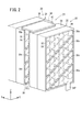
- FIG. 2 is a perspective view of the first battery module and the second battery module.
- FIG. 3 is an exploded perspective view of the first battery module and the second battery module.
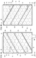
- FIG. 4A is a diagram of the first battery module as viewed from the Y axis negative direction side.
- FIG. 4B is a view of the first battery module viewed from the Y axis positive direction side.
- FIG. 5A is a view of the second battery module viewed from the Y axis negative direction side.
- FIG. 5B is a diagram of the second battery module viewed from the Y axis positive direction side.
- FIG. 6 is a schematic sectional view taken along line VI-VI in FIGS. 4A and 4B.
- FIG. 7 is a schematic diagram showing the flow of current in the first battery module and the second battery module.
- FIG. 1 is a perspective view of the battery pack 10.
- FIG. 2 is a perspective view of the first battery module 22 and the second battery module 24. 1 and 2 show an X axis, a Y axis, and a Z axis orthogonal to each other. In other drawings described below, X-axis, Y-axis, and Z-axis corresponding to X-axis, Y-axis, and Z-axis in FIGS. 1 and 2 are shown.
- the battery pack 10 includes a case 14, a first battery module 22 and a second battery module 24 housed inside the case 14.
- the case 14 includes a top case 16, a bottom case 18, and an outer case 20.
- FIG. 3 is an exploded perspective view of the first battery module 22 and the second battery module 24.
- Each of the first battery module 22 and the second battery module 24 has a plurality of cells 26, a cell holder 28 accommodating the cells 26, and lead plates 30a to 30p connecting the cells 26 to each other. .
- the cell 26 is a lithium ion secondary battery having a cylindrical appearance.
- the unit cell 26 is not limited to a lithium ion secondary battery, and may be another secondary battery such as a nickel hydride secondary battery or a nickel cadmium secondary battery.
- the cell holder 28 has a plurality of cylindrical accommodation holes 32 penetrating in the Y-axis direction. The cell 26 is accommodated in the accommodation hole 32 of the cell holder 28.
- FIG. 4A is a diagram of the first battery module 22 viewed from the Y axis negative direction side.
- FIG. 4B is a diagram of the first battery module 22 viewed from the Y axis positive direction side.
- the number of the positive electrodes of the unit cells 26 facing the Y-axis negative direction side is 24, Are arranged so that the number facing the Y axis negative direction side is 18.
- the number of the unit cells 26 in the state where the positive electrode of the unit cell 26 is directed to the Y-axis positive direction side is 18 in the state of being housed in the housing hole 32 of the first battery module 22.
- the number of the negative electrodes facing the Y-axis positive direction is 24.
- the unit cell 26 When the first battery module 22 is viewed from the negative side of the Y-axis direction or the positive side of the Y-axis, the unit cell 26 is disposed in the first region R1 formed in a substantially rectangular shape.
- the cells 26 are linearly arranged in a first direction substantially parallel to the direction of gravity (Z-axis direction), and are linearly arranged in a second direction that is oblique to the direction of gravity (Z-axis direction). It is arranged in.
- the first direction may not be a direction substantially parallel to the direction of gravity, and the second direction is not a direction oblique to the direction of gravity if it is a direction oblique to the first direction. May be.
- first region R1 regions formed by substantially triangles at corners of the first region R1 on the Z axis negative direction side and the positive direction side are referred to as second regions R2a and R2b, respectively.
- the cells 26 arranged in the second region R2a and the second region R2b have electrodes of the same polarity, respectively. It is provided so that it becomes.
- the cells 26 arranged in the second region R2a and the second region R2b are provided such that the electrodes of the cells 26 adjacent to each other in the first direction have the same polarity, and Are provided so that the electrodes of the unit cells 26 adjacent to each other in the same direction have the same polarity.
- the number of the cells 26 arranged in the second region R2a and the second region R2b is six each, and the number of the single cells 26 in the second direction is set at a position adjacent to the second region R2a or the second region R2b.
- the number is the same as the number (6) of the unit cells 26 arranged.
- the cells 26 arranged in the third region R3 are the cells 26 adjacent to each other in the first direction.
- the electrodes are provided so as to have different polarities, and the electrodes of the unit cells 26 adjacent to each other in the second direction are provided so as to have the same polarity.
- the first battery module 22 has eight lead plates 30a to 30h.
- the lead plates 30a to 30h are plate members formed of a conductive material.
- the shapes of the lead plates 30b and 30g are the same, and the shapes of the lead plates 30c to 30f are the same.
- the lead plate 30a forms a positive electrode lead plate.
- the lead plate 30a is formed in a substantially triangular shape having a straight line substantially parallel to the first direction and a straight line substantially parallel to the second direction.
- the lead plate 30a is formed with an electrode portion 34P protruding in the negative Z-axis direction with respect to the cell holder 28.
- the lead plate 30a is mounted on the negative side of the cell holder 28 in the Y-axis negative direction, and connects the positive electrodes of the cells 26 arranged in the second region R2a on the negative side of the Z-axis in parallel (FIG. 4A).
- the lead plate 30b is formed in a substantially trapezoidal shape having straight lines substantially parallel to the first direction and straight lines substantially parallel to the second direction on its sides.
- the lead plate 30b is attached to the positive side of the cell holder 28 in the Y-axis direction, connects the negative electrodes of the unit cells 26 arranged in the second region R2a in parallel, and sets the lead plate 30b at a position adjacent to the second region R2a.
- the positive electrodes of the unit cells 26 arranged in two directions are connected in parallel.
- the lead plate 30b connects the negative electrode of the cell 26 arranged in the second region R2a and the positive electrode of the cell 26 arranged in the second direction at a position adjacent to the second region R2a. Connect in series (FIG. 4B).
- the lead plate 30c is formed in a substantially parallelogram shape having a straight line substantially parallel to the first direction and a straight line substantially parallel to the second direction on its sides.
- the lead plate 30c is mounted on the negative side of the cell holder 28 in the Y-axis direction, connects the negative electrodes of the cells 26 arranged in the second direction in the third region R3 in parallel, and also in the second direction.
- the positive electrodes of the arranged cells 26 are connected in parallel.
- the lead plate 30c connects the negative electrode of the cell 26 arranged in the second direction and the positive electrode of the cell 26 arranged in the second direction in series (FIG. 4A).
- the lead plate 30d is formed in a substantially parallelogram shape having sides on a straight line substantially parallel to the first direction and a straight line substantially parallel to the second direction.
- the lead plate 30d is attached to the positive side of the cell holder 28 in the Y-axis direction, connects the negative electrodes of the cells 26 arranged in the second direction in the third region R3 in parallel, and also in the second direction.
- the positive electrodes of the arranged cells 26 are connected in parallel.
- the lead plate 30d connects the negative electrode of the cell 26 arranged in the second direction and the positive electrode of the cell 26 arranged in the second direction in series (FIG. 4B).
- the lead plate 30e is formed in a substantially parallelogram shape having a straight line substantially parallel to the first direction and a straight line substantially parallel to the second direction on its sides.
- the lead plate 30e is mounted on the negative side of the cell holder 28 in the Y-axis direction, connects the negative electrodes of the cells 26 arranged in the second direction in the third region R3 in parallel, and also in the second direction.
- the positive electrodes of the arranged cells 26 are connected in parallel.
- the lead plate 30e connects the negative electrode of the cell 26 arranged in the second direction and the positive electrode of the cell 26 arranged in the second direction in series (FIG. 4A).
- the lead plate 30f is formed in a substantially parallelogram shape having a straight line substantially parallel to the first direction and a straight line substantially parallel to the second direction on its sides.
- the lead plate 30f is mounted on the positive side of the cell holder 28 in the Y-axis direction, connects the negative electrodes of the cells 26 arranged in the second direction in the third region R3 in parallel, and also in the second direction.
- the positive electrodes of the arranged cells 26 are connected in parallel.
- the lead plate 30f connects the negative electrode of the cell 26 arranged in the second direction and the positive electrode of the cell 26 arranged in the second direction in series (FIG. 4B).
- the lead plate 30g is formed in a substantially trapezoidal shape having a straight line substantially parallel to the first direction and a straight line substantially parallel to the second direction on its sides.
- the lead plate 30g is attached to the negative side of the cell holder 28 in the Y-axis direction, connects the positive electrodes of the cells 26 arranged in the second region R2b in parallel, and sets the lead plate at a position adjacent to the second region R2b.
- the negative electrodes of the unit cells 26 arranged in two directions are connected in parallel.
- the lead plate 30g connects the positive electrode of the cell 26 arranged in the second region R2b and the negative electrode of the cell 26 arranged in the second direction at a position adjacent to the second region R2b. Connect in series (FIG. 4A).
- the lead plate 30h constitutes a negative electrode lead plate.
- the lead plate 30h is formed in a substantially triangular shape having a straight line substantially parallel to the first direction and a straight line substantially parallel to the second direction.
- the lead plate 30h is formed such that the Z-axis positive direction side is bent from the Y-axis positive direction side of the cell holder 28 along the side surface on the Z-axis positive direction side (FIG. 3).
- the lead plate 30h is attached on the Y axis positive direction side of the cell holder 28, and connects the negative electrodes of the cells 26 arranged in the second region R2b in parallel (FIG. 4B).
- FIG. 5A is a view of the second battery module 24 as viewed from the Y axis negative direction side.
- FIG. 5B is a view of the second battery module 24 viewed from the Y axis positive direction side.
- the number of the positive electrodes of the unit cells 26 facing the Y-axis negative direction side is 24, Are arranged so that the number facing the Y axis negative direction side is 18. Further, as shown in FIG. 5B, the number of the unit cells 26 which are accommodated in the accommodation holes 32 of the second battery module 24 is 18 when the positive electrodes of the unit cells 26 face the Y axis positive direction side. , The number of the negative electrodes facing the Y-axis positive direction is 24.
- the unit cell 26 is disposed in the first region R1 formed in a substantially rectangular shape.
- the cells 26 are linearly arranged in a first direction substantially parallel to the direction of gravity (Z-axis direction), and are linearly arranged in a second direction that is oblique to the direction of gravity (Z-axis direction). It is arranged in.
- regions formed in the Z-axis negative direction side and the positive direction side of the first region R1a in substantially triangular shapes are second regions R2a and R2b, respectively.
- the region excluding the second regions R2a and R2b is referred to as a third region R3.
- the cells 26 arranged in the second region R2a and the second region R2b have electrodes of the same polarity, respectively. It is provided so that it becomes.
- the cells 26 arranged in the second region R2a and the second region R2b are provided such that the electrodes of the cells 26 adjacent to each other in the first direction have the same polarity, and Are provided so that the electrodes of the unit cells 26 adjacent to each other in the same direction have the same polarity.
- the number of the cells 26 arranged in the second region R2a and the second region R2b is six each, and the number of the single cells 26 in the second direction is set at a position adjacent to the second region R2a or the second region R2b.
- the number is the same as the number (6) of the unit cells 26 arranged.
- the cells 26 arranged in the third region R3 are the cells 26 adjacent to each other in the first direction.
- the electrodes are provided so as to have different polarities, and the electrodes of the unit cells 26 adjacent to each other in the second direction are provided so as to have the same polarity.
- the second battery module 24 has eight lead plates 30i to 30p.
- the lead plates 30i to 30p are plate members formed of a conductive material.
- the shapes of the lead plates 30j and 30o are the same, and the shapes of the lead plates 30k to 30n are the same.
- the lead plate 30i constitutes a negative electrode lead plate.
- the lead plate 30i is formed in a substantially triangular shape having a straight line substantially parallel to the first direction and a straight line substantially parallel to the second direction.
- the lead plate 30i is formed with an electrode portion 34N protruding in the negative Z-axis direction with respect to the cell holder 28.
- the lead plate 30i is attached to the positive side of the cell holder 28 in the Y-axis positive direction, and connects the negative electrodes of the cells 26 arranged in the second region R2a on the negative side of the Z-axis in parallel (FIG. 5B).
- the lead plate 30j is formed in a substantially trapezoidal shape having a straight line substantially parallel to the first direction and a straight line substantially parallel to the second direction on its sides.
- the lead plate 30j is attached to the negative side of the cell holder 28 in the Y-axis direction, connects the positive electrodes of the cells 26 arranged in the second region R2a in parallel, and places the lead plate 30j at a position adjacent to the second region R2a.
- the negative electrodes of the unit cells 26 arranged in two directions are connected in parallel.
- the lead plate 30j connects the positive electrode of the cell 26 arranged in the second region R2a and the negative electrode of the cell 26 arranged in the second direction at a position adjacent to the second region R2a. Connect in series (FIG. 5A).
- the lead plate 30k is formed in a substantially parallelogram shape having a straight line substantially parallel to the first direction and a straight line substantially parallel to the second direction on its sides.
- the lead plate 30k is attached to the Y-axis positive direction side of the cell holder 28, and connects the negative electrodes of the cells 26 arranged in the second direction in the third region R3 in parallel, and also in the second direction.
- the positive electrodes of the arranged cells 26 are connected in parallel.
- the lead plate 301 connects the negative electrode of the cell 26 arranged in the second direction and the positive electrode of the cell 26 arranged in the second direction in series (FIG. 5B).
- the lead plate 30l is formed in a substantially parallelogram shape having sides on a straight line substantially parallel to the first direction and a straight line substantially parallel to the second direction.
- the lead plate 30l is attached to the Y axis negative direction side of the cell holder 28, and connects the negative electrodes of the cells 26 arranged in the second direction in parallel to the third region R3, and also in the second direction.
- the positive electrodes of the arranged cells 26 are connected in parallel.
- the lead plate 30k connects the negative electrode of the cell 26 arranged in the second direction and the positive electrode of the cell 26 arranged in the second direction in series (FIG. 5A).
- the lead plate 30m is formed in a substantially parallelogram shape having a straight line substantially parallel to the first direction and a straight line substantially parallel to the second direction on its sides.
- the lead plate 30m is attached on the Y axis positive direction side of the cell holder 28, connects the negative electrodes of the unit cells 26 arranged in the second direction in the third region R3 in parallel, and also in the second direction.
- the positive electrodes of the arranged cells 26 are connected in parallel.
- the lead plate 30m connects the negative electrode of the unit cell 26 arranged in the second direction and the positive electrode of the unit cell 26 arranged in the second direction in series (FIG. 5B).
- the lead plate 30n is formed in a substantially parallelogram shape having a straight line substantially parallel to the first direction and a straight line substantially parallel to the second direction on its sides.
- the lead plate 30n is attached on the Y axis negative direction side of the cell holder 28, connects the negative electrodes of the cells 26 arranged in the second direction in the third region R3 in parallel, and also in the second direction.
- the positive electrodes of the arranged cells 26 are connected in parallel.
- the lead plate 30n connects the negative electrode of the cell 26 arranged in the second direction and the positive electrode of the cell 26 arranged in the second direction in series (FIG. 5A).
- the lead plate 30o is formed in a substantially trapezoidal shape having straight lines substantially parallel to the first direction and straight lines substantially parallel to the second direction on its sides.
- the lead plate 30o is attached to the Y axis positive direction side of the cell holder 28, connects the negative electrodes of the cells 26 arranged in the second region R2b in parallel, and places the lead plate 30o at a position adjacent to the second region R2b.
- the positive electrodes of the unit cells 26 arranged in two directions are connected in parallel.
- the lead plate 30o connects the negative electrode of the cell 26 arranged in the second region R2b and the positive electrode of the cell 26 arranged in the second direction at a position adjacent to the second region R2b. Connect in series (FIG. 5B).
- the lead plate 30p constitutes a positive electrode lead plate.
- the lead plate 30p is formed in a substantially triangular shape having a straight line substantially parallel to the first direction and a straight line substantially parallel to the second direction.
- the lead plate 30p is formed such that the Z-axis positive direction side is bent from the Y-axis negative direction side to the Z-axis positive direction side surface of the cell holder 28 (FIG. 3).
- the lead plate 30p is attached to the negative side of the cell holder 28 in the Y-axis direction, and connects the positive electrodes of the cells 26 arranged in the second region R2b in parallel (FIG. 5A).
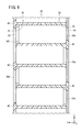
- FIG. 6 is a schematic sectional view taken along line VI-VI in FIGS. 4A and 4B.
- the unit cell 26 is not shown as a cross-sectional view.
- a common cell holder is used for the first battery module 22 and the second battery module 24.
- the cell holder 28 is formed by assembling two members, a first member 36 and a second member 38, in the Y-axis direction.
- An insulating wall 40 is formed between adjacent lead plates 30 (for example, the lead plate 30c and the lead plate 30e) attached to the cell holder 28. This prevents a short circuit between the lead plates 30. Further, the insulating wall 40 is formed so as to protrude in an inner peripheral shape of the accommodation hole 32, thereby preventing the unit cell 26 from dropping out of the accommodation hole 32.
- each of the first battery module 22 and the second battery module 24 is a single assembled battery, and the first battery module 22 and the second battery module 24 are shown in FIGS. As shown, they are connected in series by a connecting lead plate 41.
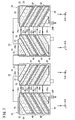
- FIG. 7 is a schematic diagram showing the flow of current in the first battery module 22 and the second battery module 24.
- the current flows through the battery pack 10 through the lead plate 30i ⁇ lead plate 30j ⁇ lead plate 30k ⁇ lead plate 30l ⁇ lead plate 30m ⁇ lead plate 30n ⁇ lead plate 30o ⁇ lead plate 30p ⁇ connection lead plate 41 ⁇ lead plate 30h ⁇
- the flow will be in the order of the lead plate 30g ⁇ the lead plate 30f ⁇ the lead plate 30e ⁇ the lead plate 30d ⁇ the lead plate 30c ⁇ the lead plate 30b ⁇ the lead plate 30a.
- both the lead plate 30a as the positive electrode lead plate of the first battery module 22 and the lead plate 30i as the negative electrode lead plate of the second battery module 24 can be arranged on the negative side of the Z axis.
- the first battery module 22 and the second battery module are configured such that a plurality of cells 26 are connected in parallel, and a plurality of cells 26 connected in parallel form a set, and the plurality of sets of cells 26 are connected in series.
- the voltage of the battery pack 10 can be increased, and the capacity can be increased.
- the first battery module 22 or the second battery module 24 is viewed from the electrode side of the unit cell 26.
- the cells 26 are linearly arranged in a first direction substantially parallel to the direction of gravity, and linearly in a second direction that is oblique to the direction of gravity. In this case, there is a problem that the shape of the lead plate connecting the individual cells 26 becomes complicated, and the productivity of the first battery module 22, the second battery module 24, and the battery pack 10 deteriorates.
- the lead plates 30c to 30f and 30k to 30n connect the unit cells 26 adjacent in the second direction in parallel, and The unit cells 26 adjacent in the direction are connected in series.
- the lead plates 30c to 30f and 30k to 30n are formed into a substantially parallelogram having sides substantially parallel to the first direction and sides substantially parallel to the second direction, and the lead plates 30c to 30f and 30k are formed. 30n can be simplified, and the productivity of the first battery module 22, the second battery module 24, and the battery pack 10 can be improved.
- the plurality of cells 26 are arranged in the first region R1 formed in a substantially rectangular shape, and the corners in the first region R1 are formed.
- the number of the cells 26 arranged in the second region R2 formed in a substantially triangular portion is the same as the number of the cells 26 arranged in the second direction at a position adjacent to the second region R2. It is.
- the cells 26 arranged in the second region R2 are connected in parallel by the lead plates 30b, 30g, 30j, and 30o, and are arranged in the second direction at a position adjacent to the second region R2.
- the unit cells 26 arranged in the direction can be connected in series.
- the lead plates 30b, 30g, 30j, and 30o are formed in a substantially trapezoidal shape having sides substantially parallel to the first direction and sides substantially parallel to the second direction, and the lead plates 30b, 30g, 30j, and 30o. Can be simplified, and the productivity of the first battery module 22, the second battery module 24, and the battery pack 10 can be improved.
- the lead plates 30a to 30p have side surfaces formed in a straight line substantially parallel to the first direction, and substantially parallel to the second direction. And a side surface formed in a parallel straight line.
- the shapes of the lead plates 30a to 30p can be simplified, and the productivity of the first battery module 22, the second battery module 24, and the battery pack 10 can be improved.
- the cell holder 28 has the insulating wall 40 between the adjacent lead plates 30a to 30p. This can prevent a short circuit between the lead plates 30a to 30p.
- the first battery module 22 moves the lead plate 30a (positive electrode lead plate) connected to only the positive electrode of the adjacent cell 26 downward in the direction of gravity (negative Z-axis direction).
- a lead plate 30h (negative electrode lead plate) connected to only the negative electrode of the adjacent cell 26 is provided above the gravity direction (positive Z-axis direction).
- the second battery module 24 adjacent to the first battery module 22 has a lead plate 30p (positive electrode lead plate) connected to only the positive electrode of the adjacent unit cell 26 above (in the positive Z-axis direction) in the direction of gravity.
- a lead plate 30i (negative electrode lead plate) connected to only the negative electrode of the adjacent unit cell 26 is provided below the gravity direction (negative Z-axis direction).
- the lead plate 30h of the first battery module 22 above the gravity direction and the lead plate 30p of the second battery module 24 are connected in series.
- the lead plate 30h (negative electrode lead plate) of the first battery module 22 and the lead plate 30p (positive electrode lead plate) of the second battery module 24 are both concentrated upward in the direction of gravity.
- the second battery module 24 can be easily connected in series by the connecting lead plate 41.
- lead plate 30a positive lead plate
- lead plate 30h negative lead plate
- lead plate 30p of first battery module 22 and second battery module 24 connected in series are provided.
- the lead plate 30i negative electrode lead plate
- the lead plate 30a positive electrode lead plate
- the lead plate 30i negative electrode lead plate
- both the lead plate 30a (positive lead plate) of the first battery module 22 and the lead plate 30i (negative lead plate) of the second battery module 24, which are electrodes of the battery pack 10 are concentrated below in the direction of gravity.
- the circuit configuration in the battery pack 10 can be simplified.
Landscapes
- Chemical & Material Sciences (AREA)
- Chemical Kinetics & Catalysis (AREA)
- Electrochemistry (AREA)
- General Chemical & Material Sciences (AREA)
- Connection Of Batteries Or Terminals (AREA)
- Battery Mounting, Suspending (AREA)
Abstract
第1電池モジュール(22)は、第1電池モジュール(22)を単電池(26)の電極側から見たときに、単電池(26)は、略平行する第1の方向に直線状に並べられるとともに、第1の方向に対して斜め方向である第2の方向に直線状に並べられ、第1の方向に互いに隣接する単電池(26)の電極は異極であって、第2の方向に互いに隣接する単電池(26)の電極は同極であり、第1の方向において隣接する単電池(26)を直列に接続し、第2の方向において隣接する単電池(26)を並列に接続するリード板(30c~30f)を有する。
Description
本発明は、円筒状の複数の単電池が、単電池の軸方向が略平行となる状態で積み重ねられて形成された電池モジュール、および、ケース内に複数の電池モジュールを有する電池パックに関する。
特開2002-254934号公報には、円筒型電池を複数本直列に接続したバッテリ組付体を複数並列に接続されているバッテリユニットが開示されている。
特開2002-254934号公報に記載の技術では、円筒型電池同士を接続する導電板が複雑な形状であって、多種類の形状の導電板が必要となるため、バッテリユニットの生産性が悪い問題がある。
本発明は、上記の問題を解決するためになされたものであり、導電板の形状を単純な形状とするとともに、導電板の形状の種類を少なくして、生産性を向上させることができる電池モジュールおよび電池パックを提供することを目的とする。
第1の発明は、円筒状の複数の単電池26が、前記単電池26の軸方向が略平行となる状態で積み重ねられて形成された電池モジュール22、24であって、以下の特徴を有する。
第1の特徴;前記電池モジュール22、24を前記単電池26の電極側から見たときに、前記単電池26は、第1の方向に直線状に並べられるとともに、前記第1の方向に対して斜め方向である第2の方向に直線状に並べられ、前記第1の方向に互いに隣接する前記単電池26の電極は異極であって、前記第2の方向に互いに隣接する前記単電池26の電極は同極であり、前記第1の方向において隣接する前記単電池26を直列に接続し、前記第2の方向において隣接する前記単電池26を並列に接続するリード板30c~30f、30k~30nを有する。
第2の特徴;前記電池モジュール22、24を前記単電池26の電極側から見たときに、複数の前記単電池26は、略長方形で形成される第1の領域R1に配置され、前記第1の領域R1内の隅部に略三角形で形成される第2の領域R2に配置された前記単電池26の本数は、前記第2の領域R2に隣接する位置に前記第2の方向に並べられている前記単電池26の本数と同数である。
第3の特徴;前記電池モジュール22、24を前記単電池26の電極側から見たときに、前記第2の領域R2に配置された前記単電池26であって、前記第1の方向に互いに隣接する前記単電池26の電極は同極である。
第4の特徴;前記電池モジュール22、24を前記単電池26の電極側から見たときに、前記リード板30c~30f、30k~30nは、前記第1の方向と略平行な直線状に形成された側面と、前記第2の方向と略平行な直線状に形成された側面とを有する。
第5の特徴;隣接する前記リード板30c~30f、30k~30nの間に絶縁壁40を有する。
第2の発明は、上記の電池モジュール22、24をケース14内に複数有する電池パック10であって、以下の特徴を有する。
第6の特徴;1つの前記電池モジュール22は、隣接する前記単電池26の正極のみと接続する正極リード板30aを前記第1の方向の一方に有するとともに、隣接する前記単電池26の負極のみと接続する負極リード板30hを前記第1の方向の他方に有し、1つの前記電池モジュール22と隣接して配置される別の前記電池モジュール24は、隣接する前記単電池26の正極のみと接続する正極リード板30pを前記第1の方向の他方に有するとともに、隣接する前記単電池26の負極のみと接続する負極リード板30iを前記第1の方向の一方に有し、1つの前記電池モジュール22と別の前記電池モジュール24とは、直列に接続されている。
第7の特徴;直列に接続された複数の前記電池モジュール22、24の前記正極リード板30a、30pおよび前記負極リード板30h、30iのうち、前記電池パック10の電極となる前記正極リード板30aおよび前記負極リード板30iを、前記第1の方向の同一方向側に設ける。
第1の発明の第1の特徴によれば、電池モジュールの生産性を向上させることができる。
第1の発明の第2の特徴によれば、電池モジュールの生産性を向上させることができる。
第1の発明の第3の特徴によれば、電池モジュールの生産性を向上させることができる。
第1の発明の第4の特徴によれば、電池モジュールの生産性を向上させることができる。
第1の発明の第5の特徴によれば、リード板同士の短絡を防ぐことができる。
第2の発明の第6の特徴によれば、電池モジュールと隣接する電池モジュールとを簡単に直列に接続することができる。
第2の発明の第7の特徴によれば、電池パック内の回路構成を単純化することができる。
上記の目的、特徴及び利点は、添付した図面を参照して説明される以下の実施の形態の説明から容易に了解されるであろう。
[電池パックの構成]
図1は電池パック10の斜視図である。図2は第1電池モジュール22および第2電池モジュール24の斜視図である。図1および図2には、互いに直交するX軸、Y軸およびZ軸が示されている。以降に説明する他の図面においても、図1および図2のX軸、Y軸およびZ軸に対応するX軸、Y軸およびZ軸が示されている。
図1は電池パック10の斜視図である。図2は第1電池モジュール22および第2電池モジュール24の斜視図である。図1および図2には、互いに直交するX軸、Y軸およびZ軸が示されている。以降に説明する他の図面においても、図1および図2のX軸、Y軸およびZ軸に対応するX軸、Y軸およびZ軸が示されている。
電池パック10は、ケース14、および、ケース14の内部に収容された第1電池モジュール22および第2電池モジュール24から構成されている。ケース14は、トップケース16、ボトムケース18、および、外装ケース20から構成されている。
[電池モジュールの構成]
図3は、第1電池モジュール22および第2電池モジュール24の分解斜視図である。第1電池モジュール22および第2電池モジュール24は、それぞれ、複数の単電池26、単電池26が収容されるセルホルダ28、および、単電池26同士を接続するリード板30a~30pを有している。
図3は、第1電池モジュール22および第2電池モジュール24の分解斜視図である。第1電池モジュール22および第2電池モジュール24は、それぞれ、複数の単電池26、単電池26が収容されるセルホルダ28、および、単電池26同士を接続するリード板30a~30pを有している。
単電池26は外観が円筒形状をしたリチウムイオン二次電池である。なお、単電池26は、リチウムイオン二次電池に限らず、ニッケル水素二次電池やニッケルカドミウム二次電池等の他の二次電池であってもよい。セルホルダ28には、Y軸方向に貫通する円筒状の複数の収容孔32が形成されている。単電池26は、セルホルダ28の収容孔32内に収容されている。
(第1電池モジュールの構成)
図4Aは、第1電池モジュール22をY軸負方向側から見た図である。図4Bは、第1電池モジュール22をY軸正方向側から見た図である。
図4Aは、第1電池モジュール22をY軸負方向側から見た図である。図4Bは、第1電池モジュール22をY軸正方向側から見た図である。
図4Aに示されるように、単電池26は、第1電池モジュール22の収容孔32に収容された状態で、単電池26の正極がY軸負方向側に向いている本数が24本、負極がY軸負方向側を向いている本数が18本となるように配置されている。また、図4Bに示されるように、単電池26は、第1電池モジュール22の収容孔32に収容された状態で、単電池26の正極がY軸正方向側に向いている本数が18本、負極がY軸正方向側を向いている本数が24本となるように配置されている。
第1電池モジュール22をY軸負方向側またはY軸正方向側から見たときに、単電池26は、略長方形で形成される第1の領域R1内に配置されている。単電池26は、重力方向(Z軸方向)に略平行する第1の方向に直線状に並べられるとともに、重力方向(Z軸方向)に対して斜めの方向である第2の方向に直線状に並べられている。
なお、第1の方向は、重力方向に略平行する方向でなくともよく、第2の方向は、第1の方向に対して斜めの方向であれば、重力方向に対して斜めの方向でなくともよい。
第1の領域R1のうち、第1の領域R1のZ軸負方向側および正方向側の隅にそれぞれ略三角形で形成される領域を第2の領域R2a、R2bとし、第1の領域R1aのうち、第2の領域R2a、R2bを除く領域を第3の領域R3とする。
第1電池モジュール22をY軸負方向側またはY軸正方向側から見たときに、第2の領域R2aおよび第2の領域R2bに配置されている単電池26は、それぞれ電極が同極となるように設けられている。換言すると、第2の領域R2aおよび第2の領域R2bに配置されている単電池26は、第1の方向に互いに隣接する単電池26の電極が同極となるように設けられるとともに、第2の方向に互いに隣接する単電池26の電極が同極となるように設けられている。
第2の領域R2aおよび第2の領域R2bに配置された単電池26の本数は、それぞれ6本であって、第2の領域R2aまたは第2の領域R2bに隣接する位置に第2の方向に並べられている単電池26の本数(6本)と同数である。
第1電池モジュール22をY軸負方向側またはY軸正方向側から見たときに、第3の領域R3に配置されている単電池26は、第1の方向に互いに隣接する単電池26の電極が異極となるように設けられるとともに、第2の方向に互いに隣接する単電池26の電極が同極となるように設けられている。
第1電池モジュール22は、8枚のリード板30a~30hを有している。リード板30a~30hは、導電性の材料により形成された板部材である。8枚のリード板30a~30hのうち、リード板30b、30gの形状は同じであり、リード板30c~30fの形状は同じである。
リード板30aは、正極リード板を構成する。リード板30aは、第1の方向と略平行な直線と第2の方向と略平行な直線とを有する略三角形状に形成されている。リード板30aは、セルホルダ28に対して、Z軸負方向側に突出する電極部34Pが形成されている。リード板30aは、セルホルダ28のY軸負方向側に取り付けられ、Z軸負方向側の第2の領域R2aに配置されている単電池26の正極を並列に接続している(図4A)。
リード板30bは、第1の方向と略平行な直線と第2の方向と略平行な直線を辺に有する略台形状に形成されている。リード板30bは、セルホルダ28のY軸正方向側に取り付けられ、第2の領域R2aに配置されている単電池26の負極を並列に接続するとともに、第2の領域R2aに隣接する位置に第2の方向に並べられている単電池26の正極を並列に接続する。さらに、リード板30bは、第2の領域R2aに配置されている単電池26の負極と、第2の領域R2aに隣接する位置に第2の方向に並べられている単電池26の正極とを直列に接続する(図4B)。
リード板30cは、第1の方向と略平行な直線と第2の方向と略平行な直線を辺に有する略平行四辺形状に形成されている。リード板30cは、セルホルダ28のY軸負方向側に取り付けられ、第3の領域R3に第2の方向に配置されている単電池26の負極を並列に接続するとともに、同じく第2の方向に配置されている単電池26の正極を並列に接続する。さらに、リード板30cは、第2の方向に配置されている単電池26の負極と、第2の方向に配置されている単電池26の正極とを直列に接続する(図4A)。
リード板30dは、第1の方向と略平行な直線と第2の方向と略平行な直線を辺に有する略平行四辺形状に形成されている。リード板30dは、セルホルダ28のY軸正方向側に取り付けられ、第3の領域R3に第2の方向に配置されている単電池26の負極を並列に接続するとともに、同じく第2の方向に配置されている単電池26の正極を並列に接続する。さらに、リード板30dは、第2の方向に配置されている単電池26の負極と、第2の方向に配置されている単電池26の正極とを直列に接続する(図4B)。
リード板30eは、第1の方向と略平行な直線と第2の方向と略平行な直線を辺に有する略平行四辺形状に形成されている。リード板30eは、セルホルダ28のY軸負方向側に取り付けられ、第3の領域R3に第2の方向に配置されている単電池26の負極を並列に接続するとともに、同じく第2の方向に配置されている単電池26の正極を並列に接続する。さらに、リード板30eは、第2の方向に配置されている単電池26の負極と、第2の方向に配置されている単電池26の正極とを直列に接続する(図4A)。
リード板30fは、第1の方向と略平行な直線と第2の方向と略平行な直線を辺に有する略平行四辺形状に形成されている。リード板30fは、セルホルダ28のY軸正方向側に取り付けられ、第3の領域R3に第2の方向に配置されている単電池26の負極を並列に接続するとともに、同じく第2の方向に配置されている単電池26の正極を並列に接続する。さらに、リード板30fは、第2の方向に配置されている単電池26の負極と、第2の方向に配置されている単電池26の正極とを直列に接続する(図4B)。
リード板30gは、第1の方向と略平行な直線と第2の方向と略平行な直線を辺に有する略台形状に形成されている。リード板30gは、セルホルダ28のY軸負方向側に取り付けられ、第2の領域R2bに配置されている単電池26の正極を並列に接続するとともに、第2の領域R2bに隣接する位置に第2の方向に並べられている単電池26の負極を並列に接続する。さらに、リード板30gは、第2の領域R2bに配置されている単電池26の正極と、第2の領域R2bに隣接する位置に第2の方向に並べられている単電池26の負極とを直列に接続する(図4A)。
リード板30hは、負極リード板を構成する。リード板30hは、第1の方向と略平行な直線と第2の方向と略平行な直線とを有する略三角形状に形成されている。リード板30hは、Z軸正方向側がセルホルダ28のY軸正方向側からZ軸正方向側の側面に沿って屈曲するように形成されている(図3)。リード板30hは、セルホルダ28のY軸正方向側に取り付けられ、第2の領域R2bに配置されている単電池26の負極を並列に接続している(図4B)。
(第2電池モジュールの構成)
図5Aは、第2電池モジュール24をY軸負方向側から見た図である。図5Bは、第2電池モジュール24をY軸正方向側から見た図である。
図5Aは、第2電池モジュール24をY軸負方向側から見た図である。図5Bは、第2電池モジュール24をY軸正方向側から見た図である。
図5Aに示されるように、単電池26は、第2電池モジュール24の収容孔32に収容された状態で、単電池26の正極がY軸負方向側に向いている本数が24本、負極がY軸負方向側を向いている本数が18本となるように配置されている。また、図5Bに示されるように、単電池26は、第2電池モジュール24の収容孔32に収容された状態で、単電池26の正極がY軸正方向側に向いている本数が18本、負極がY軸正方向側を向いている本数が24本となるように配置されている。
第2電池モジュール24をY軸負方向側またはY軸正方向側から見たときに、単電池26は、略長方形で形成される第1の領域R1内に配置されている。単電池26は、重力方向(Z軸方向)に略平行する第1の方向に直線状に並べられるとともに、重力方向(Z軸方向)に対して斜めの方向である第2の方向に直線状に並べられている。
第1の領域R1aのうち、第1の領域R1aのZ軸負方向側および正方向側の隅にそれぞれ略三角形で形成される領域を第2の領域R2a、R2bとし、第1の領域R1aのうち、第2の領域R2a、R2bを除く領域を第3の領域R3とする。
第2電池モジュール24をY軸負方向側またはY軸正方向側から見たときに、第2の領域R2aおよび第2の領域R2bに配置されている単電池26は、それぞれ電極が同極となるように設けられている。換言すると、第2の領域R2aおよび第2の領域R2bに配置されている単電池26は、第1の方向に互いに隣接する単電池26の電極が同極となるように設けられるとともに、第2の方向に互いに隣接する単電池26の電極が同極となるように設けられている。
第2の領域R2aおよび第2の領域R2bに配置された単電池26の本数は、それぞれ6本であって、第2の領域R2aまたは第2の領域R2bに隣接する位置に第2の方向に並べられている単電池26の本数(6本)と同数である。
第2電池モジュール24をY軸負方向側またはY軸正方向側から見たときに、第3の領域R3に配置されている単電池26は、第1の方向に互いに隣接する単電池26の電極が異極となるように設けられるとともに、第2の方向に互いに隣接する単電池26の電極が同極となるように設けられている。
第2電池モジュール24は、8枚のリード板30i~30pを有している。リード板30i~30pは、導電性の材料により形成された板部材である。8枚のリード板30i~30pのうち、リード板30j、30oの形状は同じであり、リード板30k~30nの形状は同じである。
リード板30iは、負極リード板を構成する。リード板30iは、第1の方向と略平行な直線と第2の方向と略平行な直線とを有する略三角形状に形成されている。リード板30iは、セルホルダ28に対して、Z軸負方向側に突出する電極部34Nが形成されている。リード板30iは、セルホルダ28のY軸正方向側に取り付けられ、Z軸負方向側の第2の領域R2aに配置されている単電池26の負極を並列に接続している(図5B)。
リード板30jは、第1の方向と略平行な直線と第2の方向と略平行な直線を辺に有する略台形状に形成されている。リード板30jは、セルホルダ28のY軸負方向側に取り付けられ、第2の領域R2aに配置されている単電池26の正極を並列に接続するとともに、第2の領域R2aに隣接する位置に第2の方向に並べられている単電池26の負極を並列に接続する。さらに、リード板30jは、第2の領域R2aに配置されている単電池26の正極と、第2の領域R2aに隣接する位置に第2の方向に並べられている単電池26の負極とを直列に接続する(図5A)。
リード板30kは、第1の方向と略平行な直線と第2の方向と略平行な直線を辺に有する略平行四辺形状に形成されている。リード板30kは、セルホルダ28のY軸正方向側に取り付けられ、第3の領域R3に第2の方向に配置されている単電池26の負極を並列に接続するとともに、同じく第2の方向に配置されている単電池26の正極を並列に接続する。さらに、リード板30lは、第2の方向に配置されている単電池26の負極と、第2の方向に配置されている単電池26の正極とを直列に接続する(図5B)。
リード板30lは、第1の方向と略平行な直線と第2の方向と略平行な直線を辺に有する略平行四辺形状に形成されている。リード板30lは、セルホルダ28のY軸負方向側に取り付けられ、第3の領域R3に第2の方向に配置されている単電池26の負極を並列に接続するとともに、同じく第2の方向に配置されている単電池26の正極を並列に接続する。さらに、リード板30kは、第2の方向に配置されている単電池26の負極と、第2の方向に配置されている単電池26の正極とを直列に接続する(図5A)。
リード板30mは、第1の方向と略平行な直線と第2の方向と略平行な直線を辺に有する略平行四辺形状に形成されている。リード板30mは、セルホルダ28のY軸正方向側に取り付けられ、第3の領域R3に第2の方向に配置されている単電池26の負極を並列に接続するとともに、同じく第2の方向に配置されている単電池26の正極を並列に接続する。さらに、リード板30mは、第2の方向に配置されている単電池26の負極と、第2の方向に配置されている単電池26の正極とを直列に接続する(図5B)。
リード板30nは、第1の方向と略平行な直線と第2の方向と略平行な直線を辺に有する略平行四辺形状に形成されている。リード板30nは、セルホルダ28のY軸負方向側に取り付けられ、第3の領域R3に第2の方向に配置されている単電池26の負極を並列に接続するとともに、同じく第2の方向に配置されている単電池26の正極を並列に接続する。さらに、リード板30nは、第2の方向に配置されている単電池26の負極と、第2の方向に配置されている単電池26の正極とを直列に接続する(図5A)。
リード板30oは、第1の方向と略平行な直線と第2の方向と略平行な直線を辺に有する略台形状に形成されている。リード板30oは、セルホルダ28のY軸正方向側に取り付けられ、第2の領域R2bに配置されている単電池26の負極を並列に接続するとともに、第2の領域R2bに隣接する位置に第2の方向に並べられている単電池26の正極を並列に接続する。さらに、リード板30oは、第2の領域R2bに配置されている単電池26の負極と、第2の領域R2bに隣接する位置に第2の方向に並べられている単電池26の正極とを直列に接続する(図5B)。
リード板30pは、正極リード板を構成する。リード板30pは、第1の方向と略平行な直線と第2の方向と略平行な直線とを有する略三角形状に形成されている。リード板30pは、Z軸正方向側がセルホルダ28のY軸負方向側からZ軸正方向側の側面に沿って屈曲するように形成されている(図3)。リード板30pは、セルホルダ28のY軸負方向側に取り付けられ、第2の領域R2bに配置されている単電池26の正極を並列に接続している(図5A)。
[セルホルダの構造]
図6は図4A、図4BにおけるVI-VI線における概略断面図である。なお、図6において、単電池26は断面図として示していない。セルホルダ28は、第1電池モジュール22と第2電池モジュール24とで共通のものが用いられる。
図6は図4A、図4BにおけるVI-VI線における概略断面図である。なお、図6において、単電池26は断面図として示していない。セルホルダ28は、第1電池モジュール22と第2電池モジュール24とで共通のものが用いられる。
セルホルダ28は、第1部材36と第2部材38の2つの部材をY軸方向に組み付けて形成されている。セルホルダ28に取り付けられる隣接するリード板30(例えば、リード板30cとリード板30e)の間には絶縁壁40が形成されている。これにより、リード板30同士の短絡を防止している。また、絶縁壁40は、収容孔32の内周型に突出して形成されている、これにより、収容孔32から単電池26が脱落することを防止している。
[電池パック内の電流の流れについて]
本実施の形態の電池パック10は、第1電池モジュール22と第2電池モジュール24のそれぞれを1つの組電池とし、第1電池モジュール22と第2電池モジュール24とが、図2、図3に示されるように連結リード板41によって直列に接続されている。
本実施の形態の電池パック10は、第1電池モジュール22と第2電池モジュール24のそれぞれを1つの組電池とし、第1電池モジュール22と第2電池モジュール24とが、図2、図3に示されるように連結リード板41によって直列に接続されている。
図7は、第1電池モジュール22および第2電池モジュール24内の電流の流れを示す模式図である。電流は、電池パック10内を、リード板30i→リード板30j→リード板30k→リード板30l→リード板30m→リード板30n→リード板30o→リード板30p→連結リード板41→リード板30h→リード板30g→リード板30f→リード板30e→リード板30d→リード板30c→リード板30b→リード板30aと流れることとなる。これにより、第1電池モジュール22の正極リード板であるリード板30aと、第2電池モジュール24の負極リード板であるリード板30iとを、ともにZ軸負方向側に配置することができる。
[作用効果]
複数の単電池26が並列に接続され、並列に接続された複数の単電池26を一組として、複数組の単電池26が直列に接続されるように第1電池モジュール22および第2電池モジュール24を構成することにより、電池パック10の電圧を高くするとともに、容量を大きくすることができる。
複数の単電池26が並列に接続され、並列に接続された複数の単電池26を一組として、複数組の単電池26が直列に接続されるように第1電池モジュール22および第2電池モジュール24を構成することにより、電池パック10の電圧を高くするとともに、容量を大きくすることができる。
第1電池モジュール22および第2電池モジュール24の小型化を図るために、本実施の形態の電池パック10では、第1電池モジュール22または第2電池モジュール24を単電池26の電極側から見たときに、単電池26は、重力方向に対して略平行する第1の方向に直線状に並べられるとともに、重力方向に対して斜め方向である第2の方向に直線状に並べられる。この場合、各単電池26を接続するリード板の形状が複雑となり、第1電池モジュール22、第2電池モジュール24および電池パック10の生産性が悪化する問題があった。
そこで、本実施の形態の第1電池モジュール22および第2電池モジュール24では、リード板30c~30f、30k~30nは、第2の方向において隣接する単電池26を並列に接続し、第1の方向において隣接する単電池26を直列に接続する。これにより、リード板30c~30f、30k~30nは、第1の方向に略平行な辺と第2の方向に略平行な辺を有する略平行四辺形状に形成され、リード板30c~30f、30k~30nの形状を単純化することができ、第1電池モジュール22、第2電池モジュール24および電池パック10の生産性を向上させることができる。
また、本実施の形態の第1電池モジュール22および第2電池モジュール24では、複数の単電池26は、略長方形で形成される第1の領域R1に配置され、第1の領域R1内の隅部に略三角形で形成される第2の領域R2に配置された単電池26の本数は、第2の領域R2に隣接する位置に第2の方向に並べられている単電池26の本数と同数である。これにより、リード板30b、30g、30j、30oによって、第2の領域R2に配置された単電池26を並列に接続するとともに、第2の領域R2に隣接する位置に第2の方向に並べられている単電池26を並列に接続し、さらに、並列に接続された第2の領域R2に配置された単電池26と、並列に接続された第2の領域R2に隣接する位置に第2の方向に並べられている単電池26とを直列に接続することができる。また、リード板30b、30g、30j、30oは、第1の方向に略平行な辺と第2の方向に略平行な辺を有する略台形状に形成され、リード板30b、30g、30j、30oの形状を単純化することができ、第1電池モジュール22、第2電池モジュール24および電池パック10の生産性を向上させることができる。
また、本実施の形態の第1電池モジュール22および第2電池モジュール24では、リード板30a~30pは、第1の方向と略平行な直線状に形成された側面と、第2の方向と略平行な直線状に形成された側面とを有する。これにより、リード板30a~30pの形状を単純化することができ、第1電池モジュール22、第2電池モジュール24および電池パック10の生産性を向上させることができる。
また、本実施の形態の第1電池モジュール22および第2電池モジュール24では、セルホルダ28は、隣接するリード板30a~30pの間に絶縁壁40を有する。これにより、リード板30a~30p同士の短絡を防ぐことができる。
また、本実施の形態の電池パック10では、第1電池モジュール22は、隣接する単電池26の正極のみと接続するリード板30a(正極リード板)を重力方向の下方(Z軸負方向側)に有するとともに、隣接する単電池26の負極のみと接続するリード板30h(負極リード板)を重力方向の上方(Z軸正方向側)に有する。さらに、第1電池モジュール22と隣接する第2電池モジュール24は、隣接する単電池26の正極のみと接続するリード板30p(正極リード板)を重力方向の上方(Z軸正方向側)に有するとともに、隣接する単電池26の負極のみと接続するリード板30i(負極リード板)を重力方向の下方(Z軸負方向側)に有する。そして、重力方向の上方にある第1電池モジュール22のリード板30hと、第2電池モジュール24のリード板30pとを直列に接続する。これにより、第1電池モジュール22のリード板30h(負極リード板)と第2電池モジュール24のリード板30p(正極リード板)がともに重力方向の上方に集約されるため、第1電池モジュール22と第2電池モジュール24とを連結リード板41によって簡単に直列に接続することができる。
また、本実施の形態の電池パック10では、直列に接続された第1電池モジュール22および第2電池モジュール24のリード板30a(正極リード板)、リード板30h(負極リード板)、リード板30p(正極リード板)およびリード板30i(負極リード板)のうち、電池パック10の電極となるリード板30a(正極リード板)およびリード板30i(負極リード板)を、重力方向の下方(Z軸負方向側)に設けた。これにより、電池パック10の電極となる第1電池モジュール22のリード板30a(正極リード板)と第2電池モジュール24のリード板30i(負極リード板)がともに重力方向の下方に集約されるため、電池パック10内の回路構成を単純化することができる。
Claims (7)
- 円筒状の複数の単電池(26)が、前記単電池(26)の軸方向が略平行となる状態で積み重ねられて形成された電池モジュール(22、24)であって、
前記電池モジュール(22、24)を前記単電池(26)の電極側から見たときに、
前記単電池(26)は、第1の方向に直線状に並べられるとともに、前記第1の方向に対して斜め方向である第2の方向に直線状に並べられ、
前記第1の方向に互いに隣接する前記単電池(26)の電極は異極であって、前記第2の方向に互いに隣接する前記単電池(26)の電極は同極であり、
前記第1の方向において隣接する前記単電池(26)を直列に接続し、前記第2の方向において隣接する前記単電池(26)を並列に接続するリード板(30c~30f、30k~30n)を有する、電池モジュール(22、24)。 - 請求項1に記載の電池モジュール(22、24)であって、
前記電池モジュール(22、24)を前記単電池(26)の電極側から見たときに、
複数の前記単電池(26)は、略長方形で形成される第1の領域(R1)に配置され、
前記第1の領域(R1)内の隅部に略三角形で形成される第2の領域(R2)に配置された前記単電池(26)の本数は、前記第2の領域(R2)に隣接する位置に前記第2の方向に並べられている前記単電池(26)の本数と同数である、電池モジュール(22、24)。 - 請求項2に記載の電池モジュール(22、24)であって、
前記電池モジュール(22、24)を前記単電池(26)の電極側から見たときに、
前記第2の領域(R2)に配置された前記単電池(26)であって、前記第1の方向に互いに隣接する前記単電池(26)の電極は同極である、電池モジュール(22、24)。 - 請求項1~3のいずれか1項に記載の電池モジュール(22、24)であって、
前記電池モジュール(22、24)を前記単電池(26)の電極側から見たときに、
前記リード板(30c~30f、30k~30n)は、前記第1の方向と略平行な直線状に形成された側面と、前記第2の方向と略平行な直線状に形成された側面とを有する、電池モジュール(22、24)。 - 請求項1~4のいずれか1項に記載の電池モジュール(22、24)であって、
隣接する前記リード板(30c~30f、30k~30n)の間に絶縁壁(40)を有する、電池モジュール(22、24)。 - 請求項1~5のいずれか1項に記載の電池モジュール(22、24)をケース(14)内に複数有する電池パック(10)であって、
1つの前記電池モジュール(22)は、隣接する前記単電池(26)の正極のみと接続する正極リード板(30a)を前記第1の方向の一方に有するとともに、隣接する前記単電池(26)の負極のみと接続する負極リード板(30h)を前記第1の方向の他方に有し、
1つの前記電池モジュール(22)と隣接して配置される別の前記電池モジュール(24)は、隣接する前記単電池(26)の正極のみと接続する正極リード板(30p)を前記第1の方向の他方に有するとともに、隣接する前記単電池(26)の負極のみと接続する負極リード板(30i)を前記第1の方向の一方に有し、
1つの前記電池モジュール(22)と別の前記電池モジュール(24)とは、直列に接続されている、電池パック(10)。 - 請求項6に記載の電池パック(10)であって、
直列に接続された複数の前記電池モジュール(22、24)の前記正極リード板(30a、30p)および前記負極リード板(30h、30i)のうち、前記電池パック(10)の電極となる前記正極リード板(30a)および前記負極リード板(30i)を、前記第1の方向の同一方向側に設ける、電池パック(10)。
Priority Applications (2)
| Application Number | Priority Date | Filing Date | Title |
|---|---|---|---|
| CN201980053304.5A CN112567569B (zh) | 2018-08-10 | 2019-07-04 | 电池模块和电池组 |
| JP2020536389A JP6997325B2 (ja) | 2018-08-10 | 2019-07-04 | 電池モジュールおよび電池パック |
Applications Claiming Priority (2)
| Application Number | Priority Date | Filing Date | Title |
|---|---|---|---|
| JP2018-151804 | 2018-08-10 | ||
| JP2018151804 | 2018-08-10 |
Publications (1)
| Publication Number | Publication Date |
|---|---|
| WO2020031576A1 true WO2020031576A1 (ja) | 2020-02-13 |
Family
ID=69415468
Family Applications (1)
| Application Number | Title | Priority Date | Filing Date |
|---|---|---|---|
| PCT/JP2019/026733 Ceased WO2020031576A1 (ja) | 2018-08-10 | 2019-07-04 | 電池モジュールおよび電池パック |
Country Status (4)
| Country | Link |
|---|---|
| JP (1) | JP6997325B2 (ja) |
| CN (1) | CN112567569B (ja) |
| TW (1) | TWI704711B (ja) |
| WO (1) | WO2020031576A1 (ja) |
Cited By (1)
| Publication number | Priority date | Publication date | Assignee | Title |
|---|---|---|---|---|
| WO2023278397A1 (en) * | 2021-06-29 | 2023-01-05 | Dana Myers | Battery pack assembly |
Citations (5)
| Publication number | Priority date | Publication date | Assignee | Title |
|---|---|---|---|---|
| JP2008097942A (ja) * | 2006-10-10 | 2008-04-24 | Sanyo Electric Co Ltd | 組電池 |
| JP2013525942A (ja) * | 2010-03-15 | 2013-06-20 | エレクトロンヴォルト, インコーポレーテッド | 相互接続モジュールシステム |
| JP2013232280A (ja) * | 2010-11-22 | 2013-11-14 | Yamaha Motor Co Ltd | 鞍乗型車両の電池パックおよび鞍乗型車両 |
| JP2016072039A (ja) * | 2014-09-29 | 2016-05-09 | 豊田合成株式会社 | バスバーモジュール |
| JP2018077933A (ja) * | 2016-11-07 | 2018-05-17 | トヨタ自動車株式会社 | 電池モジュールの製造方法 |
Family Cites Families (5)
| Publication number | Priority date | Publication date | Assignee | Title |
|---|---|---|---|---|
| JP4749774B2 (ja) * | 2005-06-16 | 2011-08-17 | 本田技研工業株式会社 | 組電池 |
| JP5496746B2 (ja) * | 2010-03-31 | 2014-05-21 | 三洋電機株式会社 | バッテリパック |
| WO2012014418A1 (ja) * | 2010-07-30 | 2012-02-02 | パナソニック株式会社 | 電池モジュール |
| JP6414139B2 (ja) * | 2016-05-24 | 2018-10-31 | トヨタ自動車株式会社 | 電池パック |
| US20190221814A1 (en) * | 2016-09-29 | 2019-07-18 | Panasonic Intellectual Property Management Co., Ltd. | Cell module |
-
2019
- 2019-07-04 CN CN201980053304.5A patent/CN112567569B/zh active Active
- 2019-07-04 JP JP2020536389A patent/JP6997325B2/ja active Active
- 2019-07-04 WO PCT/JP2019/026733 patent/WO2020031576A1/ja not_active Ceased
- 2019-08-08 TW TW108128170A patent/TWI704711B/zh active
Patent Citations (5)
| Publication number | Priority date | Publication date | Assignee | Title |
|---|---|---|---|---|
| JP2008097942A (ja) * | 2006-10-10 | 2008-04-24 | Sanyo Electric Co Ltd | 組電池 |
| JP2013525942A (ja) * | 2010-03-15 | 2013-06-20 | エレクトロンヴォルト, インコーポレーテッド | 相互接続モジュールシステム |
| JP2013232280A (ja) * | 2010-11-22 | 2013-11-14 | Yamaha Motor Co Ltd | 鞍乗型車両の電池パックおよび鞍乗型車両 |
| JP2016072039A (ja) * | 2014-09-29 | 2016-05-09 | 豊田合成株式会社 | バスバーモジュール |
| JP2018077933A (ja) * | 2016-11-07 | 2018-05-17 | トヨタ自動車株式会社 | 電池モジュールの製造方法 |
Cited By (1)
| Publication number | Priority date | Publication date | Assignee | Title |
|---|---|---|---|---|
| WO2023278397A1 (en) * | 2021-06-29 | 2023-01-05 | Dana Myers | Battery pack assembly |
Also Published As
| Publication number | Publication date |
|---|---|
| TW202015274A (zh) | 2020-04-16 |
| CN112567569B (zh) | 2023-05-16 |
| TWI704711B (zh) | 2020-09-11 |
| JP6997325B2 (ja) | 2022-01-17 |
| JPWO2020031576A1 (ja) | 2021-05-13 |
| CN112567569A (zh) | 2021-03-26 |
Similar Documents
| Publication | Publication Date | Title |
|---|---|---|
| KR20190078094A (ko) | 공간 활용성과 안전성이 향상된 원통형 전지셀 조립체 및 이를 포함하는 배터리 모듈 | |
| EP2424002B1 (en) | Battery array and battery pack having the same | |
| US20120295143A1 (en) | Electrochemical energy store and assembly of a plurality of such electrochemical energy stores | |
| CN110249444B (zh) | 电池组 | |
| JP4568067B2 (ja) | パック電池 | |
| JP5356033B2 (ja) | 中型あるいは大型サイズのバッテリパック用カートリッジ | |
| KR101782984B1 (ko) | 다방향성 연결구조를 가진 전지셀들 또는 단위모듈들을 포함하는 전지모듈 | |
| KR20180135604A (ko) | 배터리 모듈 및 이를 포함하는 배터리 팩 및 전력 저장 장치 | |
| KR20100044194A (ko) | 인터섹트하는 배터리 공동들 | |
| CN108336287A (zh) | 电池单体及电池组 | |
| JP2014203753A (ja) | 蓄電モジュール | |
| CN110767866A (zh) | 适用于模块化锂电池模组的串联端子及其制造方法 | |
| JP2015133289A (ja) | 電池モジュール及び電池モジュール用のホルダ | |
| JP2019212561A (ja) | 蓄電装置及び組電池 | |
| KR20100136107A (ko) | 배터리 팩 | |
| WO2020071394A1 (ja) | 電池モジュールおよび電池パック | |
| JP2008097942A (ja) | 組電池 | |
| EP2757613B1 (en) | Rechargeable battery pack | |
| WO2020031576A1 (ja) | 電池モジュールおよび電池パック | |
| KR20220085598A (ko) | 배터리 모듈 | |
| KR102278443B1 (ko) | 이차 전지 | |
| ES3058413T3 (es) | Batería secundaria y bloque de baterías que incluye la misma | |
| KR20140110132A (ko) | 전극리드의 위치 조절이 가능한 전지셀 | |
| JP5636893B2 (ja) | 電池 | |
| JP2019067689A (ja) | 組電池 |
Legal Events
| Date | Code | Title | Description |
|---|---|---|---|
| 121 | Ep: the epo has been informed by wipo that ep was designated in this application |
Ref document number: 19846757 Country of ref document: EP Kind code of ref document: A1 |
|
| ENP | Entry into the national phase |
Ref document number: 2020536389 Country of ref document: JP Kind code of ref document: A |
|
| NENP | Non-entry into the national phase |
Ref country code: DE |
|
| 122 | Ep: pct application non-entry in european phase |
Ref document number: 19846757 Country of ref document: EP Kind code of ref document: A1 |