WO2020031433A1 - 冷凍装置通信システム - Google Patents
冷凍装置通信システム Download PDFInfo
- Publication number
- WO2020031433A1 WO2020031433A1 PCT/JP2019/016498 JP2019016498W WO2020031433A1 WO 2020031433 A1 WO2020031433 A1 WO 2020031433A1 JP 2019016498 W JP2019016498 W JP 2019016498W WO 2020031433 A1 WO2020031433 A1 WO 2020031433A1
- Authority
- WO
- WIPO (PCT)
- Prior art keywords
- server
- wireless lan
- lan adapter
- communication
- refrigeration apparatus
- Prior art date
- Legal status (The legal status is an assumption and is not a legal conclusion. Google has not performed a legal analysis and makes no representation as to the accuracy of the status listed.)
- Ceased
Links
Images

Classifications
-
- F—MECHANICAL ENGINEERING; LIGHTING; HEATING; WEAPONS; BLASTING
- F24—HEATING; RANGES; VENTILATING
- F24F—AIR-CONDITIONING; AIR-HUMIDIFICATION; VENTILATION; USE OF AIR CURRENTS FOR SCREENING
- F24F11/00—Control or safety arrangements
- F24F11/50—Control or safety arrangements characterised by user interfaces or communication
- F24F11/56—Remote control
- F24F11/58—Remote control using Internet communication
-
- G—PHYSICS
- G06—COMPUTING OR CALCULATING; COUNTING
- G06F—ELECTRIC DIGITAL DATA PROCESSING
- G06F13/00—Interconnection of, or transfer of information or other signals between, memories, input/output devices or central processing units
-
- H—ELECTRICITY
- H04—ELECTRIC COMMUNICATION TECHNIQUE
- H04M—TELEPHONIC COMMUNICATION
- H04M11/00—Telephonic communication systems specially adapted for combination with other electrical systems
-
- H—ELECTRICITY
- H04—ELECTRIC COMMUNICATION TECHNIQUE
- H04Q—SELECTING
- H04Q9/00—Arrangements in telecontrol or telemetry systems for selectively calling a substation from a main station, in which substation desired apparatus is selected for applying a control signal thereto or for obtaining measured values therefrom
Definitions
- the present disclosure relates to a refrigeration system communication system. More specifically, the present invention relates to a refrigeration apparatus communication system capable of remotely controlling a refrigeration apparatus from a user terminal device via an electric communication line such as the Internet.
- the wireless LAN adapter determines that communication with the server has been interrupted, transmits a stop command to the refrigerator, and transmits the stop command to the refrigerator. Stop the operation of.
- the present disclosure has an object to provide a refrigeration apparatus communication system that can continue operation of a refrigeration apparatus even when communication with a server via an electric communication line is interrupted.
- the refrigeration apparatus communication system of the present disclosure includes: (1) a refrigeration apparatus, a wireless LAN adapter provided to be attached to the refrigeration apparatus, and having a function as a network communication unit of the refrigeration apparatus, a router constituting a local area network with the wireless LAN adapter, and A server capable of communicating with the router via a line, and a refrigeration apparatus communication system capable of remotely controlling the operation of the refrigeration apparatus via the electric communication line from a terminal device, When the refrigeration apparatus is remotely controlled from the server, the operation of the refrigeration apparatus is continued even after the communication between the wireless LAN adapter and the server becomes impossible.
- the refrigeration apparatus communication system of the present disclosure when the refrigeration apparatus is remotely controlled from the server, the communication line between the server and the server is interrupted for some reason, and communication between the server and the wireless LAN adapter cannot be performed. However, the refrigeration system can continue to operate.
- the wireless LAN adapter has a restart unit that restarts the wireless LAN adapter.
- the wireless LAN adapter may be restarted by the restart unit when communication with the server cannot be performed for a predetermined time.
- the restart unit of the wireless LAN adapter restarts the wireless LAN adapter when communication between the wireless LAN adapter and the server cannot be performed for a predetermined time. This restart is performed every time the predetermined time elapses.
- the wireless LAN adapter includes: A transmitting unit that periodically transmits a transmission request to the server, A receiving unit that receives a command from the server, A timer unit that counts the time from when the receiving unit does not receive the reply from the server for the transmission request transmitted from the transmitting unit for the first time, The restart unit may restart the wireless LAN adapter when the timer unit counts the predetermined time. In this case, when a predetermined time is counted by the timer unit, the restart unit restarts the wireless LAN adapter. Even when the communication line is interrupted, the refrigeration apparatus can continue operating by not instructing the refrigeration apparatus to stop operation or the like.
- the wireless LAN adapter has a function of transmitting operation information of the refrigeration system to the server, After the communication with the server is restored, the operation information that cannot be transmitted while the communication is interrupted may be transmitted to the server.
- the operation information of the refrigerating apparatus that has not been stored in the server due to the interruption of the communication line can be stored in the server by transmitting the operation information to the server by the wireless LAN adapter after the communication is restored.
- the air conditioner maintains the operation setting immediately before the communication between the wireless LAN adapter and the server is interrupted, and continues the operation. It can be. In this case, even after the communication is cut off, the wireless LAN adapter does not give an instruction to stop the operation of the refrigeration apparatus in the communication cutoff state, so that the operation of the refrigeration apparatus should be continued under the setting conditions before the communication was cut off. Can be.
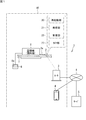
- FIG. 1 is an explanatory diagram of an embodiment of a refrigeration system communication system according to the present disclosure.
- 6 is a flowchart illustrating an operation of a restart unit of the wireless LAN adapter.
- FIG. 1 is an explanatory diagram of a refrigeration system communication system S according to an embodiment of the present disclosure.
- the refrigeration apparatus communication system S includes an air conditioner (indoor unit) 1 as a refrigeration apparatus, a wireless LAN adapter 2, a router 3, and a terminal device 4 as devices on the user 10 side.
- the refrigeration apparatus communication system S includes a server 5 that can remotely control the air conditioner 1 and remotely monitor the air conditioner 1 outside the user 10.
- the server 5 is in a state where it can communicate with the router 3 of the user 10 via the Internet 6 which is an electric communication line.
- the air conditioner 1 according to the present embodiment is a type of an air conditioner embedded in a ceiling 7 of an air conditioning room as shown in FIG.
- the remote controller 8 is connected to the air conditioner 1 via a wire, and has various operation operation functions and setting functions in addition to a display 8a for displaying various operation information and the like. Note that the remote controller 8 can also be wirelessly connected to the air conditioner 1.
- the air conditioner 1 according to the present embodiment can be remotely controlled via the server 5, and the user can use the terminal device 4 to determine the operation start time, the set temperature, and the like of the air conditioner 1 from outside the building where the air conditioner 1 is provided. Can be ordered. Further, the user can reset the set temperature with the remote control device 8 after returning to the building.
- the later (last) push priority is given to the later time setting.
- the wireless LAN adapter 2 is installed near the air conditioner 1 and is connected to a circuit board (not shown) in the air conditioner 1 via a harness 2a. Since the air conditioner 1 in the present embodiment is a ceiling embedded type, the wireless LAN adapter 2 is installed behind the ceiling.
- the wireless LAN adapter 2 connected to the air conditioner 1 has a function as a network communication unit of the air conditioner 1.
- the wireless LAN adapter 2 includes a CPU as a control unit, memories (ROM, RAM), and the like, and realizes necessary functions by executing a program (software) stored in the memory.
- the wireless LAN adapter 2 has a function as a wireless LAN access point in addition to a communication function via the air conditioner 1 and the harness 2a, and can perform network communication in the LAN.
- the wireless LAN adapter 2 includes a restart unit 20 for restarting the wireless LAN adapter 2, a transmitting unit 21, a receiving unit 22, and a timer unit 23.
- the transmission unit 21 has a function of transmitting a control data request to the server 5 periodically (for example, every eight minutes).
- the receiving unit 22 has a function of receiving a command from the server 5. Detailed operations of the restart unit 20 and the like will be described later.
- the router 3 configures a LAN (local area network) with various network devices (not shown) in the user 10 in addition to the wireless LAN adapter 2.
- the wireless LAN adapter 2 accesses the router 3 using the wireless LAN function.
- the terminal device 4 is a portable terminal device such as a tablet computer and a smartphone, and can communicate with the server 5 via the Internet 6.
- the user can remotely control the air conditioner 1 using the terminal device 4 outside a building such as a house or an office building where the air conditioner 1 is provided.
- the operation start time, operation mode (cooling operation, heating operation, dehumidification operation mode, etc.), set temperature and the like of the air conditioner at home are set by the terminal device 4, and the set information is stored in the server. 5 and the wireless LAN adapter 2 to the air conditioner 1.
- application software of a remote control system for remotely controlling the air conditioner 1 is installed, and functions such as input operation, command editing / transmission, and mail reception corresponding to the remote control system are provided. Is added to The air conditioner 1 can be remotely controlled using a web browser instead of the application software.
- the server 5 stores a wireless LAN adapter 2 attached to the air conditioner 1 to be remotely controlled, a user identification code (ID) such as a mail address of a terminal device 4 to which remote control is permitted, and a password (PW). be registered.
- ID user identification code
- PW password
- the user starts application software of the installed remote control system and inputs the ID and PW for starting remote control.
- the air conditioner 1 to be controlled is selected from the pre-registered remote control target devices, and then the contents of the control (such as the cooling or heating start time and the set temperature) are selected.
- the server 5 transmits the received command from the terminal device 4 to the wireless LAN adapter 2 as a reply to the control data request periodically transmitted from the transmission unit 21 of the wireless LAN adapter 2.
- the wireless LAN adapter 2 receives a command from the terminal device 4 transmitted from the server 5 and performs remote control of the air conditioner 1. Specifically, the wireless LAN adapter 2 transmits a command from the terminal device 4 to the control board of the air conditioner 1 via the harness 2a.
- the server 5 in the present embodiment can perform not only remote control of the air conditioner 1 but also remote monitoring of the air conditioner 1.
- the operation data set temperature, room temperature, outside temperature, etc.
- a predetermined time for example, 24 hours or 48 hours
- Displaying operating time information of the air conditioner, such as operating time, and notifying the user of the occurrence of an abnormality in the air conditioner by mail can be cited.
- the air conditioner communication system of the present embodiment when the air conditioner 1 is remotely controlled from the server 5, even after the communication between the wireless LAN adapter 2 and the server 5 is disabled, the operation of the air conditioner 1 is stopped. Let it continue.
- the interruption of communication between the wireless LAN adapter 2 and the server 5 occurs due to a failure of a device such as the wireless LAN adapter 2 or the router 3, a connection failure due to interference with another wireless device, a failure of the server, or the like.
- the location where the communication is interrupted may be between the wireless LAN adapter 2 and the router 3, between the router 3 and the server 5, and the like.
- the air conditioner 1 even if the communication line between the wireless LAN adapter 2 and the server 5 is interrupted for some reason, the air conditioner 1 continues to operate by operating the restart unit 20 of the wireless LAN adapter 2. be able to.
- the wireless LAN adapter 2 in the present embodiment does not perform control such as stopping the operation of the air conditioner 1 when the communication is interrupted. Therefore, at the time of restart described later, the air conditioner 1 can continue operating under the set conditions before the communication is cut off.
- FIG. 2 is a flowchart illustrating the operation of the restart unit 20 of the wireless LAN adapter 2.
- the server 5 receives a command for remote control of the air conditioner 1 from the user's terminal device 4 (step S1), the command is from the terminal device 4 to which remote control of the air conditioner 1 is permitted. Is confirmed by the ID or PW, control data for transmitting the contents of the command to the wireless LAN adapter 2 is generated and stored (step S2).
- the control data request is periodically transmitted to the server 5 from the transmission unit 21 of the wireless LAN adapter 2 as described above (step S10).
- step S3 the server 5 determines whether or not a control data request from the wireless LAN adapter 2 has been received. If it determines that the control data request has been received, the server 5 proceeds to step S4. It is determined whether there is control data for the wireless LAN adapter 2. When the server 5 determines in step S4 that the control data is present, the server 5 returns the control data and the date and time to the wireless LAN adapter 2 (steps S5 and S6).
- step S4 if there is no control data for the wireless LAN adapter 2 in step S4, the process proceeds to step S6, and the server 5 returns only the date and time to the wireless LAN adapter 2. If there is no control data to the wireless LAN adapter 2, it may be returned with the date and time that there is no control data.
- step S11 the control unit (not shown) of the wireless LAN adapter 2 determines whether the receiving unit 22 has received a reply from the server 5 for the control data request from the wireless LAN adapter 2, and If the reply has been received from the server 5, in step S12, the reply date and time from the server 5 is updated, and the process proceeds to step S13.
- step S13 determines in step S13 that there is control data based on a command from a user related to remote control of the air conditioner 1
- step S14 the control data is controlled in step S14.
- the data is transmitted to the air conditioner 1, which is the target device.
- step S20 the control unit mounted on the control board of the air conditioner 1 controls the operation of the air conditioner 1 according to the control data.
- step S11 when the control unit of the wireless LAN adapter 2 determines that a reply from the server 5 to the control data request from the wireless LAN adapter 2 has not been received, the control unit of the wireless LAN adapter 2 starts counting by the timer unit 23.
- step S15 it is determined whether a predetermined time has elapsed since the timer unit 23 started counting, and if it is determined that the predetermined time has elapsed, in step S16, the wireless LAN adapter 2 The restart unit operates, and the wireless LAN adapter 2 is restarted (rebooted). At this time, the wireless LAN adapter 2 does not control or instruct to stop the operation of the air conditioner 1 in response to the interruption of the communication. Therefore, the air conditioner 1 can continue operating under the set conditions before the communication is cut off.
- the predetermined time is not particularly limited, but may be, for example, 24 hours.
- step S16 Even after the restart in step S16, the wireless LAN adapter 2 periodically transmits the control data request in step S10 to the server 5. If there is no response from the server 5 to the control data request for a predetermined time, the wireless LAN adapter 2 is restarted in step S16.
- the operation of the air conditioner 1 can be continued without stopping the operation of the air conditioner 1 due to the interruption of communication with the server 5.
- the operation of the air conditioner 1 is stopped even if the communication with the server is interrupted when the air conditioner 1 is remotely controlled by the server 5. May not be desired.
- the air conditioner 1 is stopped after receiving the interruption. It is not desirable.
- the operation of the air conditioner 1 can be continued without interrupting the communication with the server 5 and the operation of the air conditioner 1 can be continued. Can be prevented from breaking down or the server going down. Further, deterioration of wine and food can be suppressed.
- the air conditioner 1 targets not only “humans” but also other animals and plants, as well as devices such as servers and PCs, beverages such as wine and ham. , Meat and other foods.
- the server 5 in the present embodiment performs not only remote control of the air conditioner 1 but also remote monitoring of the air conditioner 1.
- the contents of the remote monitoring include the display of the past operation data (set temperature, room temperature, outside temperature, etc.) of the target air conditioner 1 as a graph as described above, and the operation time information of the air conditioner such as the accumulated operation time. Is displayed.
- the wireless LAN adapter 2 has a function of transmitting various operation information of the air conditioner 1 to the server 5.
- the transmission of the operation information can be performed by the transmission unit 21 of the wireless LAN adapter 2. However, if the communication with the server 5 is interrupted, the operation information cannot be transmitted to the server 5.
- the operation information that cannot be transmitted while the communication is interrupted is stored in the storage unit of the control board of the air conditioner 1, the storage unit of the wireless LAN adapter 2, or the outdoor unit corresponding to the air conditioner 1. (Not shown), and is transmitted from the wireless LAN adapter 2 to the server 5 after the communication with the server 5 is restored.
- the operation information of the air conditioner 1 that has not been stored in the server 5 due to the interruption of the communication line can be stored in the server 5 after the communication is restored.
- the restart section 20 restarts the wireless LAN adapter.
- the wireless LAN adapter 2 does not perform control such as stopping the operation of the air conditioner 1 when the communication is interrupted at the time of the restart. Therefore, the air conditioner 1 can continue the operation while maintaining the operation setting (including the operation mode and the set temperature) immediately before the communication between the wireless LAN adapter 2 and the server 5 is cut off. In other words, the air conditioner 1 maintains the final command for the air conditioner 1. Thus, even after the communication is interrupted, the operation of the air conditioner can be continued under the setting conditions before the communication was interrupted.
- the communication with the server 5 is interrupted for some reason after a predetermined time has passed since there is no response from the server 5 for the control data request from the wireless LAN adapter 2 first.
- the wireless LAN adapter 2 is restarted.
- Information that the communication has been interrupted can be displayed on the display 8a of the terminal device 4 or the remote control device 8.
- the display of the information on the display 8a of the remote control device 8 can be performed mainly by the wireless LAN adapter 2, or can be performed mainly by the server 5.
- the air conditioner 1 is configured to continue operation even when communication with the server 5 is interrupted, but when the air conditioning load of an area to be air-conditioned by the air conditioner 1 is smaller than a predetermined value.
- the air conditioner 1 has a thermo-off function for stopping the operation of the air conditioner 1. Thereby, it is possible to save energy by operating the air conditioner 1 only when necessary.
- the ceiling-embedded indoor unit is exemplified as the air conditioner that can be remotely controlled by the server.
- the air conditioner in the present disclosure is not limited to this, and the ceiling installation type, Other types of indoor units such as a wall-mounted type and a floor-mounted type may be used.
- the wireless LAN adapter can be installed at an appropriate place such as a wall surface or inside the machine according to the type of the indoor unit.
- an air conditioner indoor unit
- the refrigeration apparatus of the present disclosure is not limited to this. And refrigerated or frozen containers.
- the temperature range of the conditioned air supplied by the refrigeration apparatus is not particularly limited, and may be, for example, 10 ° C. to 25 ° C. or ⁇ 35 ° C. to 25 ° C.
- the refrigeration apparatus in the present disclosure is intended for air conditioning of not only buildings such as houses and office buildings, but also refrigerated warehouses and frozen warehouses.
Landscapes
- Engineering & Computer Science (AREA)
- General Engineering & Computer Science (AREA)
- Theoretical Computer Science (AREA)
- Physics & Mathematics (AREA)
- Mechanical Engineering (AREA)
- Combustion & Propulsion (AREA)
- Chemical & Material Sciences (AREA)
- General Physics & Mathematics (AREA)
- Human Computer Interaction (AREA)
- Signal Processing (AREA)
- Computer Networks & Wireless Communication (AREA)
- Selective Calling Equipment (AREA)
- Air Conditioning Control Device (AREA)
- Telephonic Communication Services (AREA)
- Computer And Data Communications (AREA)
Abstract
冷凍装置1と、前記冷凍装置1に付属して設けられ、当該冷凍装置1のネットワーク通信部としての機能を有する無線LANアダプタ2と、前記無線LANアダプタ2とローカルエリアネットワークを構成するルータ3と、電気通信回線6を介して前記ルータ3と通信可能なサーバ5と、を備え、端末装置4から、前記電気通信回線6を介して前記冷凍装置1の運転を遠隔制御することができる冷凍装置通信システムS。前記冷凍装置1が前記サーバ5から遠隔制御されている場合において、前記無線LANアダプタ2とサーバ5との通信ができなくなった後も当該冷凍装置1の運転を継続させる。
Description
本開示は冷凍装置通信システムに関する。さらに詳しくは、ユーザの端末装置からインターネット等の電気通信回線を介して冷凍装置を遠隔制御することができる冷凍装置通信システムに関する。
住宅等の建物の外部から当該建物内の、冷凍装置である空調機(空気調和機)を遠隔制御することができる冷凍装置通信システムが種々提案されている(例えば、特許文献1参照)。
特許文献1に記載された冷凍装置通信システムでは、ユーザの多機能携帯電話と冷凍装置(冷凍サイクル機器)との間にメールサーバと無線LANアダプタとが配置されており、無線LANアダプタは定期的にメールサーバに送信要求を発信し、当該メールサーバからの指令があったときは、当該指令に基づいて制御対象機である冷凍装置の運転を制御する。
特許文献1に記載された冷凍装置通信システムでは、ユーザの多機能携帯電話と冷凍装置(冷凍サイクル機器)との間にメールサーバと無線LANアダプタとが配置されており、無線LANアダプタは定期的にメールサーバに送信要求を発信し、当該メールサーバからの指令があったときは、当該指令に基づいて制御対象機である冷凍装置の運転を制御する。
一方、所定時間の間、送信要求に対してメールサーバからの返信を受信しないとき、無線LANアダプタは、サーバとの通信が遮断されているとして、停止コマンドを冷凍装置に送信して当該冷凍装置の運転を停止させる。
しかし、空調の対象となる部屋ないしエリアの目的や用途によっては、冷凍装置の運転の停止を望まない場合がある。
本開示は、電気通信回線を介したサーバとの間の通信が遮断された場合でも冷凍装置の運転を継続させることができる冷凍装置通信システムを提供することを目的としている。
本開示の冷凍装置通信システムは、
(1)冷凍装置と、前記冷凍装置に付属して設けられ、当該冷凍装置のネットワーク通信部としての機能を有する無線LANアダプタと、前記無線LANアダプタとローカルエリアネットワークを構成するルータと、電気通信回線を介して前記ルータと通信可能なサーバと、を備え、端末装置から、前記電気通信回線を介して前記冷凍装置の運転を遠隔制御することができる冷凍装置通信システムであって、
前記冷凍装置が前記サーバから遠隔制御されている場合において、前記無線LANアダプタとサーバとの通信ができなくなった後も当該冷凍装置の運転を継続させる。
(1)冷凍装置と、前記冷凍装置に付属して設けられ、当該冷凍装置のネットワーク通信部としての機能を有する無線LANアダプタと、前記無線LANアダプタとローカルエリアネットワークを構成するルータと、電気通信回線を介して前記ルータと通信可能なサーバと、を備え、端末装置から、前記電気通信回線を介して前記冷凍装置の運転を遠隔制御することができる冷凍装置通信システムであって、
前記冷凍装置が前記サーバから遠隔制御されている場合において、前記無線LANアダプタとサーバとの通信ができなくなった後も当該冷凍装置の運転を継続させる。
本開示の冷凍装置通信システムでは、冷凍装置がサーバから遠隔制御されている場合に、何らかの原因でサーバとの間の通信回線が遮断され当該サーバと無線LANアダプタとの間の通信ができなくなったとしても冷凍装置は運転を継続させることができる。
(2)前記(1)の冷凍装置通信システムにおいて、前記無線LANアダプタは、当該無線LANアダプタを再起動させる再起動部を有しており、
前記サーバとの通信が所定の時間できないとき、前記再起動部により無線LANアダプタを再起動させるものとすることができる。この場合、無線LANアダプタの再起動部は当該無線LANアダプタとサーバとの間の通信が所定の時間できないときに、無線LANアダプタを再起動させる。この再起動は、前記所定の時間が経過するごとに行われる。これにより、通信回線が遮断された場合でも、冷凍装置に対し運転停止等の指示をしないことで当該冷凍装置の運転を継続させることができる。
前記サーバとの通信が所定の時間できないとき、前記再起動部により無線LANアダプタを再起動させるものとすることができる。この場合、無線LANアダプタの再起動部は当該無線LANアダプタとサーバとの間の通信が所定の時間できないときに、無線LANアダプタを再起動させる。この再起動は、前記所定の時間が経過するごとに行われる。これにより、通信回線が遮断された場合でも、冷凍装置に対し運転停止等の指示をしないことで当該冷凍装置の運転を継続させることができる。
(3)前記(2)の冷凍装置通信システムにおいて、前記無線LANアダプタは、
前記サーバに対し送信要求を定期的に発信する発信部と、
前記サーバからの指令を受信する受信部と、
前記発信部から発信された送信要求に対するサーバからの返信を前記受信部が初めて受信しないときからの時間をカウントするタイマ部と
を有しており、
前記タイマ部が前記所定の時間をカウントしたときに、前記再起動部が無線LANアダプタを再起動させるものとすることができる。この場合、タイマ部により所定の時間がカウントされると再起動部により無線LANアダプタが再起動される。通信回線が遮断された場合でも、冷凍装置に対し運転停止等の指示をしないことで当該冷凍装置は運転を継続させることができる。
前記サーバに対し送信要求を定期的に発信する発信部と、
前記サーバからの指令を受信する受信部と、
前記発信部から発信された送信要求に対するサーバからの返信を前記受信部が初めて受信しないときからの時間をカウントするタイマ部と
を有しており、
前記タイマ部が前記所定の時間をカウントしたときに、前記再起動部が無線LANアダプタを再起動させるものとすることができる。この場合、タイマ部により所定の時間がカウントされると再起動部により無線LANアダプタが再起動される。通信回線が遮断された場合でも、冷凍装置に対し運転停止等の指示をしないことで当該冷凍装置は運転を継続させることができる。
(4)前記(1)~(3)の冷凍装置通信システムにおいて、前記無線LANアダプタは、前記冷凍装置の運転情報を前記サーバに送信する機能を有しており、
サーバとの間の通信が復帰した後、通信が遮断されている間に送信不可であった運転情報を当該サーバに送信するものとすることができる。この場合、通信回線の遮断によりサーバに保存されなかった冷凍装置の運転情報は、通信復帰後に無線LANアダプタがサーバに当該運転情報を送信することでサーバに保存させることができる。
サーバとの間の通信が復帰した後、通信が遮断されている間に送信不可であった運転情報を当該サーバに送信するものとすることができる。この場合、通信回線の遮断によりサーバに保存されなかった冷凍装置の運転情報は、通信復帰後に無線LANアダプタがサーバに当該運転情報を送信することでサーバに保存させることができる。
(5)前記(1)~(4)の冷凍装置通信システムにおいて、前記空調機は、無線LANアダプタとサーバとの間の通信が遮断された直前の運転設定を維持して運転を継続させるものとすることができる。この場合、通信が遮断された後も、無線LANアダプタは通信遮断状態に対し冷凍装置の運転停止等の指示をしないため、通信が遮断される前の設定条件で冷凍装置の運転を継続させることができる。
(6)前記(1)~(5)の冷凍装置通信システムにおいて、サーバとの通信が遮断された情報を前記端末装置に送信することができる。この場合、ユーザは無線LANアダプタとサーバとの間の通信が遮断されたことを知ることができ、例えば、通信を復帰させるための処置を執ることができる。
(7)前記(1)~(6)の冷凍装置通信システムにおいて、前記冷凍装置により空調されるエリアの空調負荷が所定の値より小さいときに、当該冷凍装置の運転を停止させることが望ましい。この場合、必要なときにだけ冷凍装置を運転させることで省エネを図ることができる。
以下、添付図面を参照しつつ、本開示の冷凍装置通信システムを詳細に説明する。なお、本開示はこれらの例示に限定されるものではなく、特許請求の範囲によって示され、特許請求の範囲と均等の意味及び範囲内でのすべての変更が含まれることが意図される。
図1は、本開示の一実施形態に係る冷凍装置通信システムSの説明図である。図1に示されるように、冷凍装置通信システムSは、ユーザ10側の機器として、冷凍装置である空調機(室内機)1と、無線LANアダプタ2と、ルータ3と、端末装置4とを備えている。冷凍装置通信システムSは、ユーザ10の外部に、前記空調機1を遠隔制御するとともに当該空調機1を遠隔監視することができるサーバ5を備えている。このサーバ5は、電気通信回線であるインターネット6を介してユーザ10のルータ3と通信可能な状態である。
本実施形態における空調機1は、図1に示されるように、空調室の天井7に埋め込まれるタイプの空調機であり、リモコン装置8を備えている。リモコン装置8は、空調機1と有線接続されており、各種運転情報等を表示するディスプレイ8aの他、種々の運転操作機能及び設定機能を有する。なお、リモコン装置8は空調機1と無線接続することもできる。本実施形態における空調機1はサーバ5を介した遠隔制御が可能であり、ユーザは空調機1が配設された建物外から空調機1の運転開始時刻や設定温度等を端末装置4を用いて指令することができる。また、ユーザは、前記設定したおいた温度を建物に戻った後にリモコン装置8で再設定することができる。このように、本実施形態における空調機1の各種の運転設定は、時間的に遅い方の設定が優先される後(あと)押し優先である。
無線LANアダプタ2は、空調機1の近傍に設置され、当該空調機1内の回路基板(図示せず)とハーネス2aを介して接続されている。本実施形態における空調機1は天井埋め込み型であることから、無線LANアダプタ2は天井裏に設置されている。空調機1に接続された無線LANアダプタ2は、当該空調機1のネットワーク通信部としての機能を有する。
無線LANアダプタ2は、制御部であるCPU、メモリ(ROM,RAM)等を備えており、当該メモリに記憶されているプログラム(ソフトウェア)を実行することで、必要な機能を実現する。例えば、無線LANアダプタ2は、空調機1とハーネス2aを介しての通信機能の他、無線LANのアクセスポイントとしての機能を備えており、LANにおけるネットワーク通信を行うことができる。
無線LANアダプタ2は、当該無線LANアダプタ2を再起動させる再起動部20、発信部21、受信部22、及び、タイマ部23を有している。発信部21は、サーバ5に対して定期的に(例えば、8分毎に)制御データ要求を発信する機能を有している。受信部22は、当該サーバ5からの指令を受信する機能を有している。これら再起動部20等の詳細な作動については、後に説明をする。
ルータ3は、無線LANアダプタ2の他、ユーザ10内の図示しない種々のネットワーク機器と、LAN(ローカルエリアネットワーク)を構成する。無線LANアダプタ2は、無線LAN機能を駆使してルータ3にアクセスする。
端末装置4は、タブレットコンピュータ、スマートフォン等の携帯用の端末装置であり、インターネット6を介してサーバ5と通信可能である。ユーザは、空調機1が配設された住宅や事務所ビル等の建物外において、端末装置4を用いて当該空調機1を遠隔制御することができる。例えば、勤務先からの帰宅時に自宅の空調機の運転開始時間、運転モード(冷房運転、暖房運転、除湿運転等のモード)、設定温度等を端末装置4で設定し、当該設定した情報をサーバ5及び無線LANアダプタ2を介して空調機1に指令することができる。
端末装置4には、空調機1を遠隔制御するための遠隔制御システムのアプリケーションソフトがインストールされ、当該遠隔制御システムに対応した入力操作、コマンド編集・送信、メール受信等の機能が当該端末装置4に加えられる。なお、アプリケーションソフトに代えてウエブブラウザを用いて空調機1を遠隔制御することもできる。
初期設定において、遠隔制御の対象とする空調機1に付属の無線LANアダプタ2と、遠隔制御を許可する端末装置4のメールアドレス等のユーザ識別符号(ID)及びパスワード(PW)とがサーバ5登録される。ユーザは、遠隔制御をするときには、インストールした遠隔制御システムのアプリケーションソフトを起動させ、遠隔制御を開始するための前記ID及びPWを入力する。ついで、予め登録している遠隔制御の対象機の中から、制御する対象の空調機1を選択し、その後、制御の内容(冷房又は暖房の開始時間や設定温度等)を選択してサーバ5に送信する。
サーバ5は、受信した端末装置4からの指令を、無線LANアダプタ2の発信部21から定期的に送信される制御データ要求に対する返信として当該無線LANアダプタ2に送信する。無線LANアダプタ2は、サーバ5から送信された前記端末装置4からの指令を受けて、空調機1の遠隔制御を行う。具体的に、無線LANアダプタ2は、前記端末装置4からの指令をハーネス2aを介して空調機1の制御基板に送信する。
本実施形態におけるサーバ5は、空調機1の遠隔制御だけでなく当該空調機1の遠隔監視を行うこともできる。遠隔監視の内容としては、例えば、対象となる空調機1の過去の所定時間(例えば、24時間又は48時間)の運転データ(設定温度、室温、外気温等)をグラフで表示したり、積算運転時間等の空調機の運転時間情報を表示したり、空調機の異常発生をメールでユーザに知らせたりすることを挙げることができる。
本実施形態の空調機通信システムでは、空調機1がサーバ5から遠隔制御されている場合において、無線LANアダプタ2とサーバ5との間の通信ができなくなった後でも当該空調機1の運転を継続させる。無線LANアダプタ2とサーバ5との間の通信の遮断は、当該無線LANアダプタ2やルータ3等の機器の不具合や、他の無線機器との干渉による接続不良、サーバ側の不具合等により発生する。また、前記通信の遮断の発生個所としては、無線LANアダプタ2とルータ3との間、ルータ3とサーバ5との間等が考えられる。本実施形態では、何らかの原因で無線LANアダプタ2とサーバ5と間の通信回線が遮断されたとしても、当該無線LANアダプタ2の再起動部20を作動させることで空調機1は運転を継続させることができる。本実施形態における無線LANアダプタ2は、通信が遮断された状態に対して空調機1の運転停止等の制御を行わない。したがって、後述する再起動時において、空調機1は通信が遮断される前の設定条件で運転を継続させることができる。
図2は、無線LANアダプタ2の再起動部20の作動を説明するフローチャートである。サーバ5は、ユーザの端末装置4からの空調機1の遠隔制御の指令を受信すると(ステップS1)、当該指令が、空調機1の遠隔制御が許可された端末装置4からのものであることを前記IDやPWにより確認した後に、無線LANアダプタ2に指令の内容を伝える制御データを生成し、保存する(ステップS2)。
無線LANアダプタ2の発信部21からは、前述したようにサーバ5に対して定期的に制御データ要求が発信されている(ステップS10)。サーバ5は、ステップS3において、当該無線LANアダプタ2からの制御データ要求を受信したか否かの判断をし、当該制御データ要求を受信したと判断するとステップS4に処理を進め、当該ステップS4において、無線LANアダプタ2への制御データがあるか否かを判断する。サーバ5は、ステップS4において、この制御データがあると判断すると、当該制御データと日時とを無線LANアダプタ2に返信する(ステップS5、ステップS6)。一方、ステップS4において、無線LANアダプタ2への制御データがない場合は、ステップS6に処理を進め、サーバ5は日時だけを無線LANアダプタ2に返信する。なお、無線LANアダプタ2への制御データがない場合に、日時とともに当該制御データが「無い」ことを返信するようにしてもよい。
無線LANアダプタ2の制御部(図示せず)は、ステップS11において、当該無線LANアダプタ2からの制御データ要求に対するサーバ5からの返信を受信部22が受信したか否かを判断し、サーバ5からの返信を受信している場合は、ステップS12において、サーバ5からの返信日時を更新し、ステップS13に処理を進める。
無線LANアダプタ2の制御部は、ステップS13において空調機1の遠隔制御に係るユーザからの指令に基づく制御データがあると判断すると、ステップS14に処理を進め、当該ステップS14において前記制御データを制御対象機である空調機1に送信する。空調機1の制御基板に搭載されている制御部は、この制御データを受信すると(ステップS20)、当該制御データにしたがって空調機1の運転を制御する。
ステップS11において、無線LANアダプタ2の制御部は、当該無線LANアダプタ2からの制御データ要求に対するサーバ5からの返信を受信していないと判断すると、タイマ部23のカウントを開始させる。ステップS15において、タイマ部23がカウントを開始してから所定の時間が経過したか否かが判断され、所定の時間が経過していると判断されると、ステップS16において、無線LANアダプタ2の再起動部が作動し、当該無線LANアダプタ2は再起動(リブート)される。その際、無線LANアダプタ2は、通信の遮断に対して空調機1の運転を停止させる制御ないし指示をしない。したがって、空調機1は通信が遮断される前の設定条件で運転を継続させることができる。前記所定の時間としては、特に限定されるものではないが、例えば24時間とすることができる。
ステップS16における再起動後においても無線LANアダプタ2は、ステップS10の制御データ要求を定期的にサーバ5に送信する。そして、この制御データ要求に対してサーバ5からの返信が所定の時間ない場合は、前記ステップS16の無線LANアダプタ2の再起動が行われる。こうして、本実施形態では、従来の空調機通信システムとは異なり、サーバ5との通信遮断により空調機1の運転を停止させることはなく、当該空調機1の運転を継続させることができる。
空調の対象となる部屋ないしエリアは、その目的や用途によっては、空調機1がサーバ5により遠隔制御されている場合において当該サーバとの通信が遮断されたとしても、空調機1の運転の停止を望まない場合がある。例えば、多くのサーバが収容されているサーバルーム、温度管理が必要な食品やワイン等の貯蔵室、病室等では、通信回線が遮断されたとしても当該遮断を受けて空調機1の運転を停止させることは望ましくない。しかし、本実施形態の冷凍装置通信システムでは、サーバ5との通信遮断により空調機1の運転を停止させることはなく、当該空調機1の運転を継続させることができるので、空調の停止によりPCが故障したりサーバがダウンしたりするのを抑制することができる。また、ワインや食品の劣化を抑制することができる。なお、本明細書において、空調機1が空調の対象とするのは「ヒト」だけでなく他の動物や植物も対象としており、また、サーバやPC等の機器類、ワイン等の飲料やハム、食肉等の食品等も対象としている。
本実施形態におけるサーバ5は、空調機1の遠隔制御だけでなく当該空調機1の遠隔監視を行っている。遠隔監視の内容は、前述したような、対象となる空調機1の過去の運転データ(設定温度、室温、外気温等)のグラフでの表示や、積算運転時間等の空調機の運転時間情報の表示である。かかる遠隔監視を行うために、無線LANアダプタ2は、空調機1の種々の運転情報をサーバ5に送信する機能を有している。この運転情報の送信は、無線LANアダプタ2の発信部21により行うことができるが、サーバ5との通信が遮断すると当該運転情報をサーバ5に送信することができなくなる。本実施形態では、通信が遮断している間に送信不可であった運転情報は、空調機1の制御基板の記憶部、無線LANアダプタ2の記憶部、又は、空調機1に対応する室外機(図示せず)の記憶部に貯蔵され、サーバ5との間の通信が復帰した後、無線LANアダプタ2からサーバ5に送信される。これにより、通信回線の遮断によりサーバ5に保存されなかった空調機1の運転情報を通信復帰後にサーバ5に保存させることができる。
本実施形態では、タイマ部23により所定の時間がカウントされると再起動部20により無線LANアダプタが再起動される。無線LANアダプタ2は、かかる再起動時において通信が遮断された状態に対し空調機1の運転停止等の制御を行わない。このため、空調機1は、無線LANアダプタ2とサーバ5との通信が遮断された直前の運転設定(運転モードや設定温度等を含む)を維持して運転を継続させることができる。換言すれば、空調機1は当該空調機1に対する最終の指令を維持する。これにより、通信が遮断された後も、通信が遮断される前の設定条件で空調機の運転を継続させることができる。
本実施形態では、無線LANアダプタ2からの制御データ要求に対して最初にサーバ5からの返信がないときから所定時間経過することでサーバ5との間の通信が何らかの理由により遮断されていると判断して当該無線LANアダプタ2を再起動させている。通信が遮断されたという情報は、端末装置4やリモコン装置8のディスプレイ8aに表示させることもできる。これにより、ユーザは、無線LANアダプタ2とサーバ5との間の通信が遮断されたことを知ることができ、通信を復帰させるための処置等を執ることができる。リモコン装置8のディスプレイ8aへの前記情報の表示は、無線LANアダプタ2が主体となって行うこともできるし、また、サーバ5が主体となって行うこともできる。
本実施形態における空調機1は、サーバ5との間の通信が遮断された場合でも運転を継続させるものであるが、当該空調機1により空調されるエリアの空調負荷が所定の値より小さいときに、当該空調機1の運転を停止させるサーモオフの機能を有している。これにより、必要なときにだけ空調機1を運転させることで省エネを図ることができる。
〔その他の変形例〕
本開示は前述した実施形態に限定されるものではなく、特許請求の範囲内において種々の変更が可能である。
例えば、前述した実施形態では、サーバにより遠隔制御可能な空調機として天井埋め込み型の室内機を例示しているが、本開示における空調機はこれに限定されるのもではなく、天井設置型、壁掛け型、床置き型等、他のタイプの室内機であってもよい。この場合、無線LANアダプタは、室内機のタイプに応じて壁面や機内等、適宜の場所に設置することができる。
また、前述した実施形態では、冷凍装置として空調機(室内機)を例示しているが、本開示の冷凍装置はこれに限定されるものではなく、冷蔵倉庫、冷凍倉庫、店舗等におけるショーケース、冷蔵又は冷凍コンテナ等も含む。
本開示は前述した実施形態に限定されるものではなく、特許請求の範囲内において種々の変更が可能である。
例えば、前述した実施形態では、サーバにより遠隔制御可能な空調機として天井埋め込み型の室内機を例示しているが、本開示における空調機はこれに限定されるのもではなく、天井設置型、壁掛け型、床置き型等、他のタイプの室内機であってもよい。この場合、無線LANアダプタは、室内機のタイプに応じて壁面や機内等、適宜の場所に設置することができる。
また、前述した実施形態では、冷凍装置として空調機(室内機)を例示しているが、本開示の冷凍装置はこれに限定されるものではなく、冷蔵倉庫、冷凍倉庫、店舗等におけるショーケース、冷蔵又は冷凍コンテナ等も含む。
さらに、冷凍装置により供給される調和空気の温度範囲も特に限定されるものではなく、例えば10℃~25℃、又は-35~25℃とすることができる。換言すれば、本開示における冷凍装置は住宅や事務所ビル等の建物だけでなく、冷蔵倉庫や冷凍倉庫等の建物の空調も対象としている。
1 : 空調機(冷凍装置)
2 : 無線LANアダプタ
2a: ハーネス
3 : ルータ
4 : 端末装置
5 : サーバ
6 : インターネット(電気通信回線)
7 : 天井
8 : リモコン装置
8a: ディスプレイ
10 : ユーザ
20 : 再起動部
21 : 発信部
22 : 受信部
23 : タイマ部
S : 冷凍装置通信システム
2 : 無線LANアダプタ
2a: ハーネス
3 : ルータ
4 : 端末装置
5 : サーバ
6 : インターネット(電気通信回線)
7 : 天井
8 : リモコン装置
8a: ディスプレイ
10 : ユーザ
20 : 再起動部
21 : 発信部
22 : 受信部
23 : タイマ部
S : 冷凍装置通信システム
Claims (7)
- 冷凍装置(1)と、前記冷凍装置(1)に付属して設けられ、当該冷凍装置(1)のネットワーク通信部としての機能を有する無線LANアダプタ(2)と、前記無線LANアダプタ(2)とローカルエリアネットワークを構成するルータ(3)と、電気通信回線(6)を介して前記ルータ(3)と通信可能なサーバ(5)と、を備え、端末装置(4)から、前記電気通信回線(6)を介して前記冷凍装置(1)の運転を遠隔制御することができる冷凍装置通信システム(S)であって、
前記冷凍装置(1)が前記サーバ(5)から遠隔制御されている場合において、前記無線LANアダプタ(2)とサーバ(5)との通信ができなくなった後も当該冷凍装置(1)の運転を継続させる、冷凍装置通信システム(S)。 - 前記無線LANアダプタ(2)は、当該無線LANアダプタ(2)を再起動させる再起動部(20)を有しており、
前記サーバ(5)との通信が所定の時間できないとき、前記再起動部(20)により無線LANアダプタ(2)を再起動させる、請求項1に記載の冷凍装置通信システム(S)。 - 前記無線LANアダプタ(2)は、
前記サーバ(5)に対し送信要求を定期的に発信する発信部(21)と、
前記サーバ(5)からの指令を受信する受信部(22)と、
前記発信部(21)から発信された送信要求に対するサーバ(5)からの返信を前記受信部(22)が初めて受信しないときからの時間をカウントするタイマ部(23)と
を有しており、
前記タイマ部(23)が前記所定の時間をカウントしたときに、前記再起動部(20)が無線LANアダプタ(2)を再起動させる、請求項2に記載の冷凍装置通信システム(S)。 - 前記無線LANアダプタ(2)は、前記冷凍装置(1)の運転情報を前記サーバ(5)に送信する機能を有しており、
サーバ(5)との間の通信が復帰した後、通信が遮断されている間に送信不可であった運転情報を当該サーバ(5)に送信する、請求項1~請求項3のいずれか1項に記載の冷凍装置通信システム(S)。 - 前記冷凍装置(1)は、無線LANアダプタ(2)とサーバ(5)との間の通信が遮断された直前の運転設定を維持して運転を継続させる、請求項1~請求項4のいずれか1項に記載の冷凍装置通信システム(S)。
- サーバ(5)との通信が遮断された情報を前記端末装置(4)に送信する、請求項1~請求項5のいずれか1項に記載の冷凍装置通信システム(S)。
- 前記冷凍装置(1)により空調されるエリアの空調負荷が所定の値より小さいときに、当該冷凍装置(1)の運転を停止させる、請求項1~請求項6のいずれか1項に記載の冷凍装置通信システム(S)。
Applications Claiming Priority (2)
| Application Number | Priority Date | Filing Date | Title |
|---|---|---|---|
| JP2018-150260 | 2018-08-09 | ||
| JP2018150260 | 2018-08-09 |
Publications (1)
| Publication Number | Publication Date |
|---|---|
| WO2020031433A1 true WO2020031433A1 (ja) | 2020-02-13 |
Family
ID=69413444
Family Applications (1)
| Application Number | Title | Priority Date | Filing Date |
|---|---|---|---|
| PCT/JP2019/016498 Ceased WO2020031433A1 (ja) | 2018-08-09 | 2019-04-17 | 冷凍装置通信システム |
Country Status (2)
| Country | Link |
|---|---|
| JP (1) | JP6949899B2 (ja) |
| WO (1) | WO2020031433A1 (ja) |
Cited By (4)
| Publication number | Priority date | Publication date | Assignee | Title |
|---|---|---|---|---|
| US11936489B2 (en) | 2021-02-02 | 2024-03-19 | True Manufacturing Co., Inc. | Systems, methods, and appliances that enable regional control of refrigeration appliances |
| US12379144B2 (en) | 2022-03-10 | 2025-08-05 | True Manufacturing Co., Inc. | Ice maker and system and method for monitoring water filter of the ice maker |
| US12526682B2 (en) | 2022-07-28 | 2026-01-13 | True Manufacturing Co., Inc. | Asset management and IOT device for refrigerated appliances |
| US12613504B2 (en) | 2021-02-02 | 2026-04-28 | True Manufacturing Co., Inc. | Systems and methods for managing leased appliances |
Citations (4)
| Publication number | Priority date | Publication date | Assignee | Title |
|---|---|---|---|---|
| JP2014142099A (ja) * | 2013-01-23 | 2014-08-07 | Hitachi Appliances Inc | 空気調和機 |
| JP2014212496A (ja) * | 2013-04-22 | 2014-11-13 | 日立アプライアンス株式会社 | 冷凍サイクル機器の遠隔制御システム |
| JP2016078011A (ja) * | 2014-10-21 | 2016-05-16 | 日立工機株式会社 | 遠心機及び遠心機の運転情報収集システム |
| JP2017183905A (ja) * | 2016-03-29 | 2017-10-05 | Necプラットフォームズ株式会社 | 通信装置、通信障害復旧方法および通信障害復旧プログラム |
Family Cites Families (2)
| Publication number | Priority date | Publication date | Assignee | Title |
|---|---|---|---|---|
| JP3506487B2 (ja) * | 1994-05-20 | 2004-03-15 | 日比谷総合設備株式会社 | 病室の人体活動識別送風量制御方法及びその装置 |
| JP5279617B2 (ja) * | 2009-05-28 | 2013-09-04 | 三洋電機株式会社 | 統合管理システム、統合管理方法、統合管理装置及び統合管理プログラム |
-
2019
- 2019-04-17 WO PCT/JP2019/016498 patent/WO2020031433A1/ja not_active Ceased
- 2019-04-17 JP JP2019078346A patent/JP6949899B2/ja active Active
Patent Citations (4)
| Publication number | Priority date | Publication date | Assignee | Title |
|---|---|---|---|---|
| JP2014142099A (ja) * | 2013-01-23 | 2014-08-07 | Hitachi Appliances Inc | 空気調和機 |
| JP2014212496A (ja) * | 2013-04-22 | 2014-11-13 | 日立アプライアンス株式会社 | 冷凍サイクル機器の遠隔制御システム |
| JP2016078011A (ja) * | 2014-10-21 | 2016-05-16 | 日立工機株式会社 | 遠心機及び遠心機の運転情報収集システム |
| JP2017183905A (ja) * | 2016-03-29 | 2017-10-05 | Necプラットフォームズ株式会社 | 通信装置、通信障害復旧方法および通信障害復旧プログラム |
Cited By (7)
| Publication number | Priority date | Publication date | Assignee | Title |
|---|---|---|---|---|
| US11936489B2 (en) | 2021-02-02 | 2024-03-19 | True Manufacturing Co., Inc. | Systems, methods, and appliances that enable regional control of refrigeration appliances |
| US12613504B2 (en) | 2021-02-02 | 2026-04-28 | True Manufacturing Co., Inc. | Systems and methods for managing leased appliances |
| US12379144B2 (en) | 2022-03-10 | 2025-08-05 | True Manufacturing Co., Inc. | Ice maker and system and method for monitoring water filter of the ice maker |
| US12526682B2 (en) | 2022-07-28 | 2026-01-13 | True Manufacturing Co., Inc. | Asset management and IOT device for refrigerated appliances |
| US12532211B2 (en) | 2022-07-28 | 2026-01-20 | True Manufacturing Co., Inc. | Asset management and IOT device for refrigerated appliances |
| US12574788B2 (en) | 2022-07-28 | 2026-03-10 | True Manufacturing Co., Inc. | Asset management and IOT device for refrigerated appliances |
| US12598504B2 (en) | 2022-07-28 | 2026-04-07 | True Manufacturing Co., Inc. | Asset management and IOT device for refrigerated appliances |
Also Published As
| Publication number | Publication date |
|---|---|
| JP2020027605A (ja) | 2020-02-20 |
| JP6949899B2 (ja) | 2021-10-13 |
Similar Documents
| Publication | Publication Date | Title |
|---|---|---|
| JP6949899B2 (ja) | 冷凍装置通信システム | |
| US10670290B2 (en) | Multi air conditioner | |
| JP6044527B2 (ja) | 空調システム | |
| EP2581676B1 (en) | Air conditioning system | |
| US9546797B2 (en) | Air conditioner management device, air conditioner management system, non-transitory computer-readable recording medium and air conditioner management method | |
| JP3398676B2 (ja) | 機器の管理システム | |
| JP6051089B2 (ja) | 空調システム | |
| EP3032841B1 (en) | Indoor device, home system, control method, and program | |
| JP6251532B2 (ja) | 空調管理装置 | |
| JP2017219253A (ja) | 空気調和システム | |
| JP2017187195A (ja) | 空調制御装置、空調制御システム、空調制御方法、およびプログラム | |
| WO2015145655A1 (ja) | 空調管理システム | |
| US20100250724A1 (en) | Device for equipment apparatus, management apparatus, equipement apparatus management system, method and computer program for controlling communication between equipment apparatus and management apparatus | |
| JP4528207B2 (ja) | 集合住宅用遠隔監視制御システム | |
| US9979811B2 (en) | Controller, control system, and method for controlling control system | |
| JP5125606B2 (ja) | 空調制御システム | |
| WO2020202295A1 (ja) | 遠隔監視装置および空気調和システム | |
| JP2020009004A (ja) | 空調制御システム、集中制御装置、方法及びプログラム | |
| JP2010114835A (ja) | 設備機器の通信制御装置、管理システム及び通信制御方法 | |
| JP6599805B2 (ja) | 空調制御システム | |
| JP2019045035A (ja) | 空気調和システム | |
| JP6326527B2 (ja) | 空調管理装置 | |
| JP5139908B2 (ja) | 機器管理システム | |
| WO2020040125A1 (ja) | 空気調和機システム、空気調和機システムの制御方法、及び、空気調和機システム制御プログラム | |
| JP3821157B2 (ja) | 設備機器管理システム、管理装置、設備機器管理方法及び設備機器管理プログラム |
Legal Events
| Date | Code | Title | Description |
|---|---|---|---|
| 121 | Ep: the epo has been informed by wipo that ep was designated in this application |
Ref document number: 19848075 Country of ref document: EP Kind code of ref document: A1 |
|
| NENP | Non-entry into the national phase |
Ref country code: DE |
|
| 122 | Ep: pct application non-entry in european phase |
Ref document number: 19848075 Country of ref document: EP Kind code of ref document: A1 |