WO2020022341A1 - 熱可塑性樹脂製構造体 - Google Patents
熱可塑性樹脂製構造体 Download PDFInfo
- Publication number
- WO2020022341A1 WO2020022341A1 PCT/JP2019/028879 JP2019028879W WO2020022341A1 WO 2020022341 A1 WO2020022341 A1 WO 2020022341A1 JP 2019028879 W JP2019028879 W JP 2019028879W WO 2020022341 A1 WO2020022341 A1 WO 2020022341A1
- Authority
- WO
- WIPO (PCT)
- Prior art keywords
- thermoplastic resin
- inorganic particles
- particles
- resin structure
- mass
- Prior art date
- Legal status (The legal status is an assumption and is not a legal conclusion. Google has not performed a legal analysis and makes no representation as to the accuracy of the status listed.)
- Ceased
Links
Images
Classifications
-
- C—CHEMISTRY; METALLURGY
- C08—ORGANIC MACROMOLECULAR COMPOUNDS; THEIR PREPARATION OR CHEMICAL WORKING-UP; COMPOSITIONS BASED THEREON
- C08K—Use of inorganic or non-macromolecular organic substances as compounding ingredients
- C08K3/00—Use of inorganic substances as compounding ingredients
- C08K3/18—Oxygen-containing compounds, e.g. metal carbonyls
- C08K3/20—Oxides; Hydroxides
- C08K3/22—Oxides; Hydroxides of metals
-
- B—PERFORMING OPERATIONS; TRANSPORTING
- B29—WORKING OF PLASTICS; WORKING OF SUBSTANCES IN A PLASTIC STATE IN GENERAL
- B29C—SHAPING OR JOINING OF PLASTICS; SHAPING OF MATERIAL IN A PLASTIC STATE, NOT OTHERWISE PROVIDED FOR; AFTER-TREATMENT OF THE SHAPED PRODUCTS, e.g. REPAIRING
- B29C39/00—Shaping by casting, i.e. introducing the moulding material into a mould or between confining surfaces without significant moulding pressure; Apparatus therefor
- B29C39/22—Component parts, details or accessories; Auxiliary operations
- B29C39/24—Feeding the material into the mould
-
- C—CHEMISTRY; METALLURGY
- C08—ORGANIC MACROMOLECULAR COMPOUNDS; THEIR PREPARATION OR CHEMICAL WORKING-UP; COMPOSITIONS BASED THEREON
- C08F—MACROMOLECULAR COMPOUNDS OBTAINED BY REACTIONS ONLY INVOLVING CARBON-TO-CARBON UNSATURATED BONDS
- C08F2/00—Processes of polymerisation
- C08F2/44—Polymerisation in the presence of compounding ingredients, e.g. plasticisers, dyestuffs, fillers
-
- C—CHEMISTRY; METALLURGY
- C08—ORGANIC MACROMOLECULAR COMPOUNDS; THEIR PREPARATION OR CHEMICAL WORKING-UP; COMPOSITIONS BASED THEREON
- C08K—Use of inorganic or non-macromolecular organic substances as compounding ingredients
- C08K3/00—Use of inorganic substances as compounding ingredients
- C08K3/34—Silicon-containing compounds
- C08K3/36—Silica
-
- C—CHEMISTRY; METALLURGY
- C08—ORGANIC MACROMOLECULAR COMPOUNDS; THEIR PREPARATION OR CHEMICAL WORKING-UP; COMPOSITIONS BASED THEREON
- C08K—Use of inorganic or non-macromolecular organic substances as compounding ingredients
- C08K3/00—Use of inorganic substances as compounding ingredients
- C08K3/40—Glass
-
- C—CHEMISTRY; METALLURGY
- C08—ORGANIC MACROMOLECULAR COMPOUNDS; THEIR PREPARATION OR CHEMICAL WORKING-UP; COMPOSITIONS BASED THEREON
- C08L—COMPOSITIONS OF MACROMOLECULAR COMPOUNDS
- C08L101/00—Compositions of unspecified macromolecular compounds
-
- C—CHEMISTRY; METALLURGY
- C08—ORGANIC MACROMOLECULAR COMPOUNDS; THEIR PREPARATION OR CHEMICAL WORKING-UP; COMPOSITIONS BASED THEREON
- C08L—COMPOSITIONS OF MACROMOLECULAR COMPOUNDS
- C08L33/00—Compositions of homopolymers or copolymers of compounds having one or more unsaturated aliphatic radicals, each having only one carbon-to-carbon double bond, and only one being terminated by only one carboxyl radical, or of salts, anhydrides, esters, amides, imides or nitriles thereof; Compositions of derivatives of such polymers
- C08L33/04—Homopolymers or copolymers of esters
- C08L33/06—Homopolymers or copolymers of esters of esters containing only carbon, hydrogen and oxygen, which oxygen atoms are present only as part of the carboxyl radical
- C08L33/10—Homopolymers or copolymers of methacrylic acid esters
- C08L33/12—Homopolymers or copolymers of methyl methacrylate
-
- C—CHEMISTRY; METALLURGY
- C08—ORGANIC MACROMOLECULAR COMPOUNDS; THEIR PREPARATION OR CHEMICAL WORKING-UP; COMPOSITIONS BASED THEREON
- C08K—Use of inorganic or non-macromolecular organic substances as compounding ingredients
- C08K3/00—Use of inorganic substances as compounding ingredients
- C08K3/18—Oxygen-containing compounds, e.g. metal carbonyls
- C08K3/20—Oxides; Hydroxides
- C08K3/22—Oxides; Hydroxides of metals
- C08K2003/2227—Oxides; Hydroxides of metals of aluminium
-
- C—CHEMISTRY; METALLURGY
- C08—ORGANIC MACROMOLECULAR COMPOUNDS; THEIR PREPARATION OR CHEMICAL WORKING-UP; COMPOSITIONS BASED THEREON
- C08K—Use of inorganic or non-macromolecular organic substances as compounding ingredients
- C08K3/00—Use of inorganic substances as compounding ingredients
- C08K3/18—Oxygen-containing compounds, e.g. metal carbonyls
- C08K3/20—Oxides; Hydroxides
- C08K3/22—Oxides; Hydroxides of metals
- C08K2003/2237—Oxides; Hydroxides of metals of titanium
- C08K2003/2241—Titanium dioxide
Definitions
- the present disclosure relates to a thermoplastic resin structure.
- Thermoplastic resins are used for various applications because they can have excellent transparency, mechanical properties and moldability.
- thermoplastic resin has been attracting attention as a glass substitute in various applications, its durability, particularly its abrasion resistance is not sufficient, so that in order to improve the abrasion resistance, a sheet of silica containing polymethyl methacrylate contains silica.
- Patent Literature 1 for example, has been developed in which a sheet is coated with a thermosetting resin composition and has improved scratch resistance.
- thermoplastic resin structure is processed into various shapes depending on the application.
- the plastic body having the surface coating described in Patent Document 1 has a certain degree of abrasion resistance, wrinkles and cracks may occur in the coating during processing.
- an object of the present disclosure is to provide a thermoplastic resin structure having excellent scratch resistance and processability.
- thermoplastic resin structure satisfying the following (1) and (2).
- the content of the inorganic particles in the structure is less than 0.8 parts by mass based on 100 parts by mass of the thermoplastic resin.
- the number of inorganic particles identified by image analysis of the SEM image of the surface of the structure is N / ⁇ m 2 , the average diameter of the particles equivalent to a circle is d ⁇ m, the standard deviation is ⁇ m, and the area of the visual field is S ⁇ m 2 ,
- thermoplastic resin structure according to the above [1], wherein the area ratio of the inorganic particles is at least 2% on at least one surface of the structure.
- thermoplastic resin structure according to any one of [1] to [5], having a single-layer structure.
- a lamp cover including the thermoplastic resin structure according to any one of [1] to [6].
- thermoplastic resin structure excellent in scratch resistance and workability.
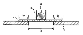
- FIG. 1 is a diagram for explaining a heating bending test.
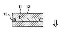
- FIG. 2 is a diagram for explaining cast polymerization.
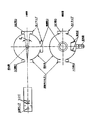
- FIG. 3 is a diagram for explaining JIS ⁇ K ⁇ 7136.
- thermoplastic resin structure of the present disclosure will be described in detail.
- thermoplastic resin structure of the present disclosure includes a thermoplastic resin.
- the thermoplastic resin may be a transparent thermoplastic resin.
- thermoplastic resin examples include (meth) acrylic resin, polycarbonate resin, polyetherimide resin, polyester resin, etc., polystyrene resin, polyethersulfone resin, fluororesin, ABS (acrylonitrile-butadiene-styrene) resin, AS (Acrylonitrile-styrene) resin, polyvinyl chloride and polyolefin resin.
- the thermoplastic resin used can be appropriately selected according to desired properties.
- the thermoplastic resin may be one kind or a mixture of two or more kinds. From the viewpoint of transparency and scratch resistance, a (meth) acrylic resin is preferable, and a methacrylic resin is more preferable. These may be used alone or in combination of two or more.
- (meth) acrylic resin includes acrylic resins and methacrylic resins.
- the methacrylic resin is a polymer having a monomer unit derived from a monomer having a methacrylic group.
- the methacrylic resin examples include a methacryl homopolymer containing only a monomer unit derived from an alkyl methacrylate having an alkyl group having 1 to 4 carbon atoms; an alkyl methacrylate having an alkyl group having 1 to 4 carbon atoms. Is from 85% by weight to less than 100% by weight and is derived from another vinyl monomer copolymerizable with a monomer unit derived from an alkyl methacrylate having an alkyl group having 1 to 4 carbon atoms. A methacrylic copolymer having more than 0% by weight and 15% by weight or less of a monomer unit to be used.
- alkyl methacrylate having an alkyl group having 1 to 4 carbon atoms is a compound represented by CH 2 CHCH (CH 3 ) COOR (R is an alkyl group having 1 to 4 carbon atoms).
- the vinyl monomer copolymerizable with the alkyl methacrylate having an alkyl group having 1 to 4 carbon atoms means that the vinyl monomer is copolymerizable with the alkyl methacrylate having an alkyl group having 1 to 4 carbon atoms and has a vinyl group. It is a monomer.
- alkyl methacrylate having an alkyl group having 1 to 4 carbon atoms examples include methyl methacrylate, ethyl methacrylate, n-propyl methacrylate, isopropyl methacrylate, n-butyl methacrylate, tert-butyl methacrylate, methacrylic acid. Sec-butyl acid and isobutyl methacrylate.
- the alkyl methacrylate having an alkyl group having 1 to 4 carbon atoms is preferably methyl methacrylate.
- the above alkyl methacrylates may be used alone or in combination of two or more.
- Examples of the vinyl monomer copolymerizable with the alkyl methacrylate having an alkyl group having 1 to 4 carbon atoms include cyclohexyl methacrylate, benzyl methacrylate, 2-ethylhexyl methacrylate, 2-hydroxyethyl methacrylate, and methacrylic acid.
- Methacrylates such as hydroxypropyl acrylate and monoglycerol methacrylate (excluding alkyl methacrylate having an alkyl group having 1 to 4 carbon atoms); methyl acrylate, ethyl acrylate, propyl acrylate, butyl acrylate, acrylic Acrylic acid esters such as 2-ethylhexyl acrylate, 2-hydroxyethyl acrylate, 2-hydroxypropyl acrylate, and monoglycerol acrylate; acrylic acid, methacrylic acid, maleic acid, itaconic acid, maleic anhydride, Unsaturated carboxylic acids such as conic acid or anhydrides thereof; nitrogen-containing monomers such as acrylamide, methacrylamide, acrylonitrile, methacrylonitrile, diacetone acrylamide, dimethylaminoethyl methacrylate; allyl glycidyl ether, glycidyl acrylate, methacryl Epoxy group-containing monomers such as
- the method for producing the methacrylic resin includes a vinyl monomer copolymerizable with an alkyl methacrylate having an alkyl group having 1 to 4 carbon atoms and, if necessary, an alkyl methacrylate having an alkyl group having 1 to 4 carbon atoms.
- the “polycarbonate resin” is a polycarbonate resin containing a structural unit derived from a dihydroxy compound.
- the polycarbonate resin that can be used as the thermoplastic resin in the present disclosure include, for example, those obtained by reacting a dihydroxy compound such as dihydric phenol or isosorbide with a carbonylating agent by an interfacial polycondensation method or a melt transesterification method. Those obtained by polymerizing a carbonate prepolymer by a solid phase transesterification method or the like; and those obtained by polymerizing a cyclic carbonate compound by a ring-opening polymerization method.
- dihydric phenol examples include hydroquinone, resorcinol, 4,4′-dihydroxydiphenyl, bis (4-hydroxyphenyl) methane, bis ⁇ (4-hydroxy-3,5-dimethyl) phenyl ⁇ methane, 1,1- Bis (4-hydroxyphenyl) ethane, 1,1-bis (4-hydroxyphenyl) -1-phenylethane, 2,2-bis (4-hydroxyphenyl) propane (commonly known as bisphenol A), 2,2-bis ⁇ (4-hydroxy-3-methyl) phenyl ⁇ propane, 2,2-bis ⁇ (4-hydroxy-3,5-dimethyl) phenyl ⁇ propane, 2,2-bis ⁇ (4-hydroxy-3,5-dibromo ) Phenyl ⁇ propane, 2,2-bis ⁇ (3-isopropyl-4-hydroxy) phenyl ⁇ propane, 2,2-bis ⁇ (4 -Hydroxy-3-phenyl) phenyl ⁇ propane, 2,2-bis (4-hydroxyphenyl)
- bisphenol A 2,2-bis ⁇ (4-hydroxy-3-methyl) phenyl ⁇ propane, 2,2-bis (4-hydroxyphenyl) butane, 2,2-bis (4 -Hydroxyphenyl) -3-methylbutane, 2,2-bis (4-hydroxyphenyl) -3,3-dimethylbutane, 2,2-bis (4-hydroxyphenyl) -4-methylpentane, 1,1-bis (4-Hydroxyphenyl) -3,3,5-trimethylcyclohexane and ⁇ , ⁇ ′-bis (4-hydroxyphenyl) -m-diisopropylbenzene are preferred.
- bisphenol A alone or bisphenol A with 1,1-bis (4-hydroxyphenyl) -3,3,5-trimethylcyclohexane, 2,2-bis ⁇ (4-hydroxy-3-methyl) phenyl It is preferably used in combination with at least one selected from the group consisting of ⁇ propane and ⁇ , ⁇ '-bis (4-hydroxyphenyl) -m-diisopropylbenzene.
- carbonylating agent examples include carbonyl halides (such as phosgene), carbonate esters (such as diphenyl carbonate), and haloformates (such as dihaloformate of dihydric phenol). These may be used alone or in combination of two or more.
- the monomer and / or polymer which is a raw material of the thermoplastic resin is obtained by mixing the monomer and / or polymer with the inorganic particles and dispersing the inorganic particles under conditions where the polymerization of the monomer and / or polymer is not started. It is sufficient that at least a part of the inorganic particles settles when the dispersion liquid is allowed to stand.
- the cup viscosity of the monomer and / or polymer that is the raw material of the thermoplastic resin of the present disclosure is preferably 0.1 seconds or more and 18 seconds or less, more preferably 0.5 seconds or more and 15 seconds or less. And more preferably 1 second or more and 13 seconds or less. If the cup viscosity of the monomer and / or polymer is less than 0.1 second, the inorganic particles settle in a short time, so when transferring the monomer and / or polymer in which the inorganic particles are dispersed from the mixing container to the polymerization container, The inorganic particles settle at the bottom of the mixing container, and a predetermined amount of the inorganic particles cannot be transferred to the polymerization container.
- cup viscosity of the monomer and / or polymer is more than 18 seconds, the inorganic particles do not settle in the polymerization vessel, and the cast plate after polymerization has poor scratch resistance.
- a monomer and / or polymer before heating used in the cast polymerization was used as a sample, and the time required for the sample to pass through a cylinder having a truncated cone shape was defined as a cup viscosity according to the following procedure.
- the cylinder having the shape of the truncated cone was made of stainless steel and had an upper surface inner diameter of 37 mm, a lower surface inner diameter of 5 mm, and a height of 65 mm.
- the thermoplastic resin structure of the present disclosure includes inorganic particles.
- the thermoplastic resin structure of the present disclosure has excellent scratch resistance by containing inorganic particles.
- the shape of the inorganic particles may be a substantially spherical shape, a rectangular parallelepiped shape, a pulverized shape having a plurality of corners, or the like.
- the shape of the inorganic particles is preferably substantially spherical, and more preferably true spherical.
- the average primary particle size of the inorganic particles used in the present disclosure is 0.01 ⁇ m or more and 10 ⁇ m or less, more preferably 0.3 ⁇ m or more and 1.5 ⁇ m or less, and still more preferably 0.3 ⁇ m or more and 1.0 ⁇ m or less.
- the average primary particle diameter can be measured by, for example, a laser diffraction type particle size distribution analyzer.
- the average particle diameter (diameter) of the inorganic particles is preferably 0.01 ⁇ m or more and 10 ⁇ m or less, more preferably 0.3 ⁇ m or more and 2 ⁇ m or less, and still more preferably 0.3 ⁇ m or less. It is 1.8 ⁇ m or less.
- the average major axis of the inorganic particles is preferably 0.01 ⁇ m or more and 10 ⁇ m or less, more preferably more than 0.3 ⁇ m and 2 ⁇ m or less.
- the “major axis” means the length of the longest part of the particle at the linear distance.
- the average major axis and the average particle diameter can be measured by reading from an image of the particles observed by a scanning electron microscope.
- the inorganic particles include at least one selected from the group consisting of silica (SiO 2 ) particles, silica composite oxide particles, alumina (Al 2 O 3 ) particles, titania (TiO 2 ) particles, and glass filler particles. No.
- the silica composite oxide is a material in which part of the silicon (Si) element in silica is replaced by another element, that is, a material in which silicon and another element form an oxide having a uniform structure.
- Means The structure of such a silica composite oxide can be analyzed by an X-ray absorption fine structure (XAFS) spectrum.
- XAFS X-ray absorption fine structure
- the other elements are not particularly limited as long as they are elements other than silicon and oxygen and can form an oxide having a uniform structure with silicon.
- the other elements include elements from Group 2 to Group 14, preferably, titanium, zirconium, aluminum, zinc, chromium, manganese, magnesium, cerium, boron, iron, indium, and tin.
- the other element is titanium, zirconium or aluminum, and more preferably titanium.
- the silica composite oxide can be a silica-titania composite oxide, a silica-zirconia composite oxide, or a silica-alumina composite oxide, preferably, a silica-titania composite oxide, or It is a silica-zirconia composite oxide, more preferably a silica-titania composite oxide.
- the content of other elements contained in the silica composite oxide particles is preferably 0.01 to 10 mol%, more preferably 0.1 to 10 mol%, based on all atoms of the silica composite oxide. 55 mol%.
- the content of other elements contained in the silica composite oxide can be measured by an ICP-AES method, a SEM-EDX method, a TEM-EDX method, or the like.
- the silica composite oxide particles preferably have a refractive index of 1.47 or more and 1.60 or less, more preferably 1.48 or more and 1.52 or less, and even more preferably 1.49 or more and 1.51 or less.
- the refractive index means a refractive index of a light beam having a wavelength of 589 nm measured at 25 ° C.
- the difference between the refractive index of the thermoplastic resin and the refractive index of the silica composite oxide particles when irradiated with light having a wavelength of 589 nm at 25 ° C. is preferably 0.03 or less, more preferably 0.02 or less, More preferably, it is 0.01 or less. Particularly preferably, both have the same refractive index.
- a molded article of the resin composition having high transparency can be obtained.
- a molded article having higher transparency can be obtained.
- the refractive index of the thermoplastic resin can be measured by a critical angle method, a V block method, a liquid immersion method, or the like. Further, the refractive index of the silica composite oxide particles can be measured by using a liquid immersion method or the like.
- the silica composite oxide particles can be obtained by a known method such as a flame melting method, a flame hydrolysis method, a sol-gel method and the like.
- glass filler examples include glass fiber, glass beads, glass powder, glass flake, and the like.
- the above glass filler preferably has a refractive index of 1.47 or more and 1.60 or less, more preferably 1.49 or more and 1.51 or less.
- the difference between the refractive index of the thermoplastic resin and the refractive index of the glass filler when irradiated with a light beam having a wavelength of 589 nm at 25 ° C. is preferably 0.03 or less, more preferably 0.02 or less, and still more preferably It is 0.01 or less. Particularly preferably, both have the same refractive index.
- the refractive index of the thermoplastic resin can be measured by a critical angle method, a V block method, a liquid immersion method, or the like. Further, the refractive index of the glass filler can be measured using a liquid immersion method or the like.
- glass filler examples include CF0093-01 (T1) (glass frit, average particle diameter: 1 ⁇ m, refractive index: 1.50), and CF0093-P5 (T4) (glass frit, average particle diameter, manufactured by Nippon Frit Co., Ltd.). : 1 ⁇ m, refractive index: 1.50) and RXFX (8901) manufactured by Nippon Sheet Glass Co., Ltd. (glass flake, average particle size: 40 ⁇ m, refractive index: 1.49), and the like.
- the thermoplastic resin structure of the present disclosure may contain an ultraviolet absorber, an antioxidant, a release agent, an antistatic agent, a flame retardant, and the like, as necessary.
- the ultraviolet absorber include a benzophenone ultraviolet absorber, a cyanoacrylate ultraviolet absorber, a benzotriazole ultraviolet absorber, a malonic ester ultraviolet absorber, and an oxalanilide ultraviolet absorber.
- examples thereof include a phenolic antioxidant, a sulfuric antioxidant, and a phosphorus-based antioxidant.
- the release agent include higher fatty acid esters, higher fatty alcohols, higher fatty acids, higher fatty acid amides, and higher fatty acid metal salts. And fatty acid derivatives.
- antistatic agent examples include conductive inorganic particles, tertiary amines, quaternary ammonium salts, cationic acrylate derivatives, and cationic vinyl ether derivatives.
- conductive inorganic particles tertiary amines, quaternary ammonium salts, cationic acrylate derivatives, and cationic vinyl ether derivatives.
- cyclic nitrogen compounds phosphorus-based flame retardants, silicon-based flame retardants, cage silses Kiokisan or partially cleaved structures thereof, and silica-based flame retardant and the like.
- the thermoplastic resin structure of the present disclosure may contain a coloring agent such as a dye or a pigment. Although the transparency is impaired by containing the coloring agent, the thermoplastic resin structure of the present disclosure has good coloring properties and can be colored in various colors.
- the coloring agent include perylene dyes, perinone dyes, pyrazolone dyes, methine dyes, coumarin dyes, quinophthalone dyes, quinoline dyes, anthraquinone dyes, anthraquinone dyes, asdrapyridone dyes, and thioindigo dyes.
- the thermoplastic resin structure of the present disclosure satisfies the following (1) and (2).
- the content of the inorganic particles in the structure is less than 0.8 part by mass based on 100 parts by mass of the thermoplastic resin.
- the number of inorganic particles identified from image analysis of the SEM image of the surface of the structure is N / ⁇ m 2 , the average circle-equivalent diameter of the particles is d ⁇ m, the standard deviation is ⁇ m, and the area of the visual field is S ⁇ m 2 .
- the content of the inorganic particles is less than 0.8 part by mass with respect to 100 parts by mass of the thermoplastic resin.
- the content of the inorganic particles is preferably 0.1 parts by mass or less, more preferably 0.03 parts by mass or less, further preferably 0.027 parts by mass or less, particularly preferably 100 parts by mass of the thermoplastic resin. It is 0.009 parts by mass or less.
- the content of the inorganic particles is preferably at least 0.0010 parts by mass, more preferably at least 0.0016 parts by mass, based on 100 parts by mass of the thermoplastic resin. Preferably it is 0.003 parts by mass or more.
- the content of the inorganic particles in the thermoplastic resin structure is preferably at least 0.0010 parts by mass or more based on 100 parts by mass of the thermoplastic resin.
- a structure having higher scratch resistance can be obtained.
- a structure having higher scratch resistance can be obtained.
- the content of the inorganic particles in the thermoplastic resin structure can be measured by ICP-AES (Inductively Coupled Plasma-Atomic Emission Spectrometry).
- ICP-AES Inductively Coupled Plasma-Atomic Emission Spectrometry
- the structure to be measured is formed into a sheet having a thickness of 3 mm, and a test piece cut into a 1 cm square is quantified by ICP-AES to determine the weight of the silicon element in the test piece.
- This quantitative value is defined as A (unit: ppm), and B (unit: ppm) represented by the following formula is defined as the silica concentration.
- B A ⁇ 60/28 (In the formula, 60 is the chemical formula weight of silica, and 28 is the atomic weight of silicon.)
- the structure to be measured is made into a sheet having a thickness of 3 mm, and a test piece cut into a 1 cm square is quantified by ICP-AES to determine the weight of the silicon element and the titanium element in the test piece. I do.
- the silicon element, the titanium element, and the oxygen element may be uniformly dispersed in some cases.
- the silica concentration and the titania concentration are respectively calculated, and the total value can be determined as the silica-titania concentration. That is, the quantitative value of the silicon element is A (unit: ppm), and B (unit: ppm) represented by the following formula is the silica concentration.
- B A ⁇ 60.1 / 28.1 (In the formula, 60 is the chemical formula weight of silica, and 28 is the atomic weight of silicon.)
- the quantitative value of the titanium element is defined as C (unit: ppm), and D (unit: ppm) represented by the following formula is defined as the titania concentration.
- D C ⁇ 79.9 / 47.9 (In the formula, 79.9 is the chemical formula weight of titania, and 47.9 is the atomic weight of titanium.)
- the area ratio of the inorganic particles on at least one surface of the thermoplastic resin structure of the present disclosure is 0.5% or more.
- the area ratio of the inorganic particles is defined by the following equation.
- d is a circle equivalent average diameter ( ⁇ m) of the inorganic particles.
- ⁇ is the standard deviation of d ( ⁇ m).
- S is the area ( ⁇ m 2 ) of the visual field of the SEM image. )
- the area ratio of the inorganic particles is preferably at least 0.8%, more preferably at least 2%, further preferably at least 3%, still more preferably at least 10%, particularly preferably at least 20%, particularly preferably at least 25%. % Or more. By increasing the area ratio of the inorganic particles, a structure having higher scratch resistance can be obtained.
- the area ratio of the inorganic particles is preferably 80% or less, more preferably 50% or less, and further preferably 30% or less. By making the area ratio of the inorganic particles smaller, a structure having higher transparency can be obtained.
- the thermoplastic resin structure of the present disclosure has an area ratio of inorganic particles of 0.5% or more, and preferably 2% or more on one surface, and an inorganic particle on a surface facing the surface.
- the area ratio of the particles is 0.1% or less, preferably 0.01% or less.
- thermoplastic resin structure of the present disclosure has high transparency because the content of the inorganic particles is small in the entire structure.
- thermoplastic resin structure of the present disclosure has high scratch resistance on at least one surface since the area ratio of the inorganic particles is 0.5% or more on at least one surface.
- thermoplastic resin structure of the present disclosure has a haze of 4% or less, preferably 3% or less, more preferably 1% or less, measured according to JIS K7136.
- the thermoplastic resin structure of the present disclosure has a ⁇ haze of less than 1.0%, preferably 0.5% or less, more preferably 0.1% or less.
- the ⁇ haze means that # 0000 steel wool is pressed at a pressure of 14 kPa against a flat surface of a structure made of a thermoplastic resin (the surface is a surface having an area ratio of inorganic particles of 0.5% or more). This is the change in haze (%) from the initial haze (%) when 11 reciprocations were rubbed at a speed of 15 cm / sec in a direction perpendicular to the fiber direction of steel wool.
- the method of measuring haze according to JIS K 7136 is as follows.
- the device consists of a stable light source, a connecting optics, an integrating sphere with an aperture and a photometer, the photometer consisting of a light receiver, a signal processing device and a display or recorder (see FIG. 3). . 3-2.
- the light source and the photometer used are a photopic standard luminous efficiency V ( ⁇ ) (defined in IEC 60050-845) whose characteristics of the combination pass through a filter and are equal to the color matching function y ( ⁇ ) according to ISO / CIE10527.
- the output of the photometer must be proportional to the incident light flux within 1% over the range of light flux used.
- the light source is to be combined with the optical system to create a parallel light beam.
- the maximum angle between any rays included in this light beam and the optical axis must not exceed 0.05 rad (3 °).
- This luminous flux must not be smeared at either opening of the integrating sphere.
- the device must be designed so that the readings are constant in the absence of the light flux.
- An integrating sphere is used to collect the transmitted light flux.
- the diameter of the integrating sphere may be any value as long as the area of the entire opening does not exceed 3.0% of the inner area of the integrating sphere.
- the diameter of the integrating sphere is desirably 150 mm or more so that a large sample can be measured. 3-6.
- the integrating sphere has an entrance aperture, an exit aperture, a compensation aperture, and a light-receiving aperture (see FIG. 3).
- the centers of the inlet and outlet openings are on the same great circle of the sphere, and the central angle of the arc on the great circle corresponding to the center between the openings is 3.14 rad ⁇ 0.03 rad (180 ⁇ 2 °).
- the angle formed by the diameter of the outlet opening with respect to the center of the inlet opening is 0.140 rad ⁇ 0.002 rad (8 ⁇ 0.1 °).
- the outlet opening and the compensating opening have the same size.
- the entrance aperture, the compensation aperture and the receiving aperture must not be on the same great circle of the integrating sphere.
- the compensating aperture is provided at a position where the central angle with the entrance aperture is within 1.57 rad (90 °). 3-7. If no sample is placed at the inlet opening, the cross section of the light beam at the outlet opening must be substantially circular and clear, concentric with the outlet opening, and an annular portion must remain around the outlet opening. The angle that the annulus makes with the center of the inlet opening is 0.023 rad ⁇ 0.002 rad (1.3 ° ⁇ 0.1 °). 3-8. A light-shielding plate is attached to the integrating sphere so that the light passing through the sample is not directly detected by the light receiver.
- the light receiver shall have a central angle of 1.57 rad ⁇ 0.26 rad (90 ° ⁇ 15 °) from the entrance aperture on the integrating sphere.
- the light traps placed at the exit and compensation apertures must either completely absorb the light in the absence of the sample or the device must be designed such that the exit and compensation apertures do not require light traps. . 3-9. It was determined by ISO772-2, the inner surface of the integrating sphere, light-shielding plate and the reference white plate (usually, which is fed from the device manufacturer.) Tristimulus values Y 10 90% or more and its variation of ⁇ 3% Must be within range.
- the test specimen holder shall fix the test specimen to the luminous flux at right angles within ⁇ 2 ° and mount the test specimen as close as possible to the integrating sphere so as to capture all transmitted light including diffused light.
- the holder shall be capable of holding a flexible test piece flat.
- the thin, flexible film is preferably sandwiched between the ends of a double ring-shaped holder or attached to the end of the holder using double-sided adhesive tape. The latter method is also used for thick specimens that cannot be mounted on a double ring holder.
- Test piece 4-1 The test piece is cut out from a film, a sheet, or a molded product by injection molding or compression molding. 4-2. Specimens shall be free of defects, dust, grease, adhesive from protective materials, scratches, debris, etc. and shall be free of visible voids and foreign matter. 4-3. The specimen is large enough to cover the entrance and compensation openings of the integrating sphere. A disk having a diameter of 50 mm or a square having a side of 50 mm is preferable. 4-4. Unless otherwise specified, three test pieces are prepared for each sample of the test material. 5. Condition adjustment 5-1.
- test specimen is conditioned by ISO 291 at a temperature (23 ⁇ 2) ° C. and a relative humidity (50 ⁇ 10)% for 40 hours or more before the test.
- test apparatus is installed in an atmosphere maintained at a temperature (23 ⁇ 2) ° C. and a relative humidity (50 ⁇ 10)%. 6.
- Procedure 6-1 The test equipment is allowed sufficient time before testing to reach thermal equilibrium.
- 6-2. Attach the test piece to the test piece holder.
- the four values ( ⁇ 1, ⁇ 2, ⁇ 3 and ⁇ 4) shown in the table below are read from the instrument.
- the thickness of the test piece is measured at three places, and is accurately measured to 0.02 mm for a sheet and 1 ⁇ m for a film.
- the above procedure is sequentially performed on three test pieces. 7.
- ⁇ 1 luminous flux of incident light
- ⁇ 2 total luminous flux transmitted through the test piece
- ⁇ 3 luminous flux scattered by the apparatus
- ⁇ 4 luminous flux diffused by the apparatus and the test piece
- Reference Total light transmittance is accurately obtained using a single beam apparatus.
- a test piece must be placed in the compensating aperture (as specified in ISO 13468-1) instead of an optical trap. This is to cancel the change in the efficiency of the integrating sphere.
- the measurement value can be corrected and obtained using a standard test piece calibrated by a double beam device.
- a standard test piece calibrated by a double beam device since there is almost no difference in the obtained haze value, it is practically sufficient to use ⁇ 1 obtained by placing an optical trap instead of a test piece in the correction aperture.
- the thickness of the thermoplastic resin structure of the present disclosure may be preferably 0.3 to 100 mm, more preferably 0.5 to 20 mm, further preferably 1 to 10 mm, and more preferably 1 to 5 mm. By setting the thickness of the thermoplastic resin structure in the above range, a structure excellent in strength and transparency can be obtained.
- the thickness of the thermoplastic resin structure of the present disclosure is 0.3 to 100 mm, more preferably 0.5 to 20 mm, still more preferably 1 to 10 mm, and more preferably 1 to 5 mm.
- the haze measured according to K7136 is 4% or less, preferably 3% or less, more preferably 1% or less.
- the thickness of the thermoplastic resin structure of the present disclosure is 1 to 5 mm, and the haze measured according to JIS K7136 is 3% or less, preferably 1% or less.
- the inorganic particles are unevenly distributed on at least one surface side of the thermoplastic resin structure.
- the inorganic particles are preferably unevenly distributed from the surface of the thermoplastic resin structure to a depth of 100 ⁇ m, more preferably to a depth of 20 ⁇ m, further preferably to a depth of 10 ⁇ m, and still more preferably to 5 ⁇ m.
- the thickness of the region where the inorganic particles are present is preferably 100 ⁇ m or less, more preferably 20 ⁇ m or less, further preferably 10 ⁇ m or less, and still more preferably 5 ⁇ m or less.
- distributed unevenly means, among the inorganic particles in the thermoplastic resin structure of the present disclosure, preferably 80% by mass or more, more preferably 90% by mass or more, still more preferably 95% by mass or more, particularly Preferably at least 98% by weight, most preferably substantially all, of the inorganic particles are present in the given range.
- the thermoplastic resin structure of the present disclosure has a single-layer structure.
- the “single-layer structure” means a structure having no interface by lamination in the layer. In the present disclosure, even when the composition of the upper part and the lower part of the layer are completely different, when the composition of both layers continuously changes in the layer, it is regarded as a single-layer structure.
- thermoplastic resin structure of the present disclosure inorganic particles are preferably unevenly distributed on one surface side.
- the inorganic particles are most present on the surface of one surface, and continuously decrease as they enter the interior (that is, as they approach the opposing surface side).
- the thermoplastic resin structure of the present disclosure has a multilayer structure. That is, the thermoplastic resin structure of the present disclosure may be a laminate.
- the “multi-layer structure” means a structure having an interface by lamination in the layer.
- thermoplastic resin structure of the present disclosure preferably has inorganic particles only in one outermost layer.
- thermoplastic resin structure of the present disclosure does not have a coating layer made of a curable resin composition. Since the thermoplastic resin structure does not have a coating layer, it is possible to prevent wrinkles from occurring during processing.
- the coating layer means a substance that gives a film-like insoluble matter when the structure is immersed in chloroform.
- the thermoplastic resin structure of the above embodiment does not produce a film-like insoluble matter when immersed in chloroform.
- the shape of the thermoplastic resin structure of the present disclosure is not particularly limited, and may be a shape according to the use.
- the shape of the thermoplastic resin structure may be a film, a sheet, a plate, a block, or the like.
- the shape of the thermoplastic resin structure is a vehicle lamp cover, a visor, a vehicle exterior material such as a front grill, a vehicle interior material such as a meter cover or a vehicle display front panel, a window or the like. It may be in the form of building materials such as sound insulation walls, furniture such as signboards and table tops, display shelves, exteriors such as carports, front panels of displays, and lighting fixture members such as covers and gloves.
- thermoplastic resin structure of the present disclosure has high scratch resistance and can have high transparency.
- a vehicle exterior material such as a vehicle lamp cover, a visor, and a front grille can be used.
- Interior materials for vehicles such as meter covers and front panels of vehicle displays, building materials such as windows and sound insulation walls, furniture such as signboards and table tops, display shelves, carports and other exterior panels, display front panels, covers and gloves It is suitably used as a lighting fixture member or the like.
- the present disclosure provides a vehicle lamp cover, a visor, a vehicle exterior material such as a front grill, a vehicle interior material such as a meter cover and a vehicle front panel, a window and a sound insulation wall, including the thermoplastic resin structure of the present disclosure.
- a vehicle lamp cover a visor
- a vehicle exterior material such as a front grill
- a vehicle interior material such as a meter cover and a vehicle front panel
- a window and a sound insulation wall including the thermoplastic resin structure of the present disclosure.
- vehicle lamp cover examples include headlights (head lamps), tail lights (tail lamps), brake lights (stop lamps), turn indicators (turn signals), fog lights (fog lamps), vehicle width lights, and reverse light covers.
- headlights head lamps
- tail lights tail lamps
- brake lights stop lamps
- turn indicators turn signals
- fog lights fog lights
- vehicle width lights and reverse light covers.
- the molded article and laminate of the present disclosure can suppress surface scratches other than scratches, for example, scratches caused by collision of particles such as sand.
- thermoplastic resin structure of the present disclosure Next, a method for manufacturing the thermoplastic resin structure of the present disclosure will be described.
- thermoplastic resin structure of the present disclosure is not particularly limited as long as the method can provide a thermoplastic resin structure satisfying the above conditions (1) and (2).
- the thermoplastic resin structure of the present disclosure may be obtained by allowing a mixture of a raw material monomer and / or a polymer and inorganic particles to stand, allowing the inorganic particles to settle on the lower surface, and then polymerizing, or Alternatively, a layer containing particles and a layer not containing inorganic particles may be separately prepared, and may be obtained by laminating these layers.
- the thermoplastic resin structure of the present disclosure is manufactured by allowing a mixture of the raw material monomer and / or polymer and the inorganic particles to stand, allowing the inorganic particles to settle on the lower surface, and then polymerizing.
- the thermoplastic resin structure of the present disclosure is manufactured using a cast polymerization method.
- a raw material is prepared by preparing two support plates, typically a glass plate and a gasket, and sandwiching the gasket between the support plates facing each other at a predetermined distance. (Hereinafter, also referred to as a “cell”).
- the distance between the support plates can be appropriately adjusted so as to obtain a structure having a desired thickness.
- the distance between the support plates can be preferably 0.3 to 100 mm, more preferably 0.5 to 20 mm, still more preferably 1 to 10 mm, more preferably 1 to 5 mm.
- the dispersion liquid can be obtained by mixing a liquid monomer and / or polymer with inorganic particles, degassing, and dispersing the inorganic particles by ultrasonic waves or the like.
- the dispersion may contain other components such as a polymerization initiator.
- the dispersion liquid obtained above is poured into a cell, and one of the support plates is placed vertically below, and the other support plate is placed vertically upward, and left standing. The standing is performed until the inorganic particles in the dispersion in the vicinity of the support plate settle to a desired density under the condition that the polymerization of the monomer and / or the polymer is not started.
- a structure made of a thermoplastic resin having excellent scratch resistance it is better to increase the inorganic particles in the dispersion near the support plate, and it is sufficient to allow the dispersion to stand until the dispersion reaches a steady state.
- the time required for production be short, and the dispersion be allowed to stand for a shorter period of time than when the dispersion reaches a steady state.
- the viscosity of the dispersion and the standing time may be selected.
- thermoplastic resin structure of the present disclosure After standing, the monomer and / or polymer is polymerized to obtain the thermoplastic resin structure of the present disclosure.
- the polymerization conditions can be appropriately set according to the raw materials used.
- thermoplastic resin structure obtained by the above method the precipitated inorganic particles are unevenly distributed on one surface side.
- a test piece obtained by cutting a sheet to be measured into 1 cm square was quantified by the ICP-AES method for the weight of the silicon element and the titanium element in the test piece.
- the quantitative value of the silicon element was defined as A (unit: ppm), and B (unit: ppm) represented by the following formula was defined as the silica concentration.
- B A ⁇ 60/28
- 60 is the chemical formula weight of silica
- 28 is the atomic weight of silicon.
- the quantitative value of the titanium element was defined as C (unit: ppm), and D (unit: ppm) represented by the following formula was defined as the titania concentration.
- the surface of the sheet to be evaluated was magnified by a scanning electron microscope at a magnification of 1000 times to obtain an enlarged image of a visual field of 130 ⁇ m ⁇ 90 ⁇ m.
- the area S ⁇ m 2 was calculated from the size of the visual field.
- the contrast of the obtained image was binarized, the number of each particle was counted, and the number N (unit: particles / ⁇ m 2 ) of inorganic particles existing per unit area was calculated.
- the radius of a circle having an area equivalent to the average of the particle areas was calculated as a circle-equivalent average diameter d (unit: ⁇ m).
- the sheet to be evaluated was cut out into a size of 70 mm ⁇ 120 mm to obtain a measurement sample.
- the width t 2 from the end 20mm of the sample 2 is placed samples 2 to ride on the plate 1, the central portion of the sample of 620g A disposable cup 4 containing a weight 3 was placed. Thereafter, the sample was heated to 110 ° C., and the sample was bent.
- the heating was stopped, and the presence or absence of wrinkles on the surface was visually checked. The absence of wrinkles means that the heat bending workability is good.
- the heating temperature is preferably 110 ° C., but in the case of other substrates, a similar evaluation can be performed by appropriately setting a different temperature and searching for a condition in which the disposable cup is lowered by 10 mm from the initial position. .
- the monomer and / or polymer before heating used in the cast polymerization was used as a sample, and the time required for the sample to pass through a cylinder having a truncated cone shape was defined as the cup viscosity according to the following procedure.
- the cylinder having the shape of the truncated cone used had an upper surface inner diameter of 37 mm, a lower surface inner diameter of 5 mm, and a height of 65 mm.
- silica particles Admafine (registered trademark) SO-C2 (average particle diameter: 0.5 ⁇ m) Admatechs Co., Ltd.
- silica particles Admafine (registered trademark) SO-C5 (average particle diameter: 1.5 ⁇ m)
- Silica-titania SiTi0849 (average particle size: 0.8 ⁇ m, refractive index: 1.49)
- Example 1 ⁇ Cast polymerization>
- 100 parts by mass of methyl methacrylate, 0.08 parts by mass of sodium di- (2-ethylhexyl) sulfosuccinate, 0.01 parts by mass of terpinolene, 0.08 parts by mass of 2,2′-azobisisobutyronitrile Were dissolved and 0.003 parts by mass of SO-C2 was added.
- the cup viscosity of methyl methacrylate was 1.6 seconds.
- silica particles were dispersed by ultrasonic waves to prepare an inorganic particle dispersion.
- This inorganic particle dispersion 11 is poured into a cell constituted by sandwiching a 3.8 mm thick vinyl chloride resin gasket 13 between two glass plates 12 as shown in FIG. Side (in the direction of the arrow in FIG. 2), the other glass plate was placed in an oven such that it was vertically above, and allowed to stand at room temperature for 30 minutes. Then, it heated according to the following conditions, and polymerized the inorganic particle dispersion liquid, and obtained the 3-mm-thick acrylic plate.
- Step 1 Heat from room temperature to 72 ° C. over 30 minutes
- Step 2 Hold at 70 ° C. for 70 minutes
- Step 3 Cool from 72 ° C. to 68 ° C. over 20 minutes
- Step 4 Hold at 68 ° C. for 60 minutes
- Step 5 Heat from 68 ° C to 120 ° C over 30 minutes
- Step 6 Hold at 120 ° C for 40 minutes
- Step 7 Cool from 120 ° C to room temperature over 75 minutes
- Table 1 shows the evaluation results of the obtained acrylic plate. The surface that was vertically below in the oven was used as the evaluation surface.
- Example 2 An acrylic plate was obtained in the same manner as in Example 1, except that 0.03 parts by mass of SO-C2 was added. Table 1 shows the evaluation results. The surface that was vertically below in the oven was used as the evaluation surface.
- methacrylic resin A in a pellet form.
- the content of monomer units derived from methyl methacrylate was 97.5% by weight
- the content of monomer units derived from methyl acrylate was 2.5% by weight
- MFR was 2 g / 10 min.
- Extruder temperature The eight heaters from the raw material inlet to the outlet were set at 200 ° C., 200 ° C., 210 ° C., 220 ° C., 230 ° C., 240 ° C., 240 ° C., and 250 ° C. from the raw material inlet side, respectively.
- Rotation speed 200 rpm
- Feeding speed of raw material 12 kg / hour
- Comparative Example 2 At the time of melt-kneading, an acrylic plate was obtained in the same manner as in Comparative Example 1, except that 1 part by mass of SO-C2 was added to 100 parts by mass of methacrylic resin A and mixed. Table 1 shows the evaluation results. In addition, the surface on the core side of the mold during the injection molding was used as the evaluation surface.
- Comparative Example 3 During the melt kneading, an acrylic plate was obtained in the same manner as in Comparative Example 1, except that SO-C2 was not added to 100 parts by mass of the methacrylic resin A. Table 1 shows the evaluation results. In addition, the surface on the core side of the mold during the injection molding was used as the evaluation surface.
- Example 3 A black acrylic plate was prepared in the same manner as in Example 2 except that the inorganic particle dispersion was obtained by adding 0.45 parts by mass of Sumiplast Black HB (black dye) manufactured by Sumika ChemteX Corporation to the inorganic particle dispersion of Example 2. I got The surface that was vertically below in the oven was used as the evaluation surface. Because of the black color, the transmitted light was small and the haze was difficult to measure. Therefore, the scratch resistance was evaluated based on the change in the specular gloss at 20 degrees. That is, the evaluation surface was rubbed eleven times with a load of 14 kPa at a speed of 15 cm / sec using # 0000 steel wool.
- Sumiplast Black HB black dye manufactured by Sumika ChemteX Corporation
- the 20-degree specular gloss of the evaluation surface before and after the abrasion test was measured, and the change ( ⁇ gloss (unit:%)) of the 20-degree specular gloss before and after the test was calculated.
- ⁇ gloss was -0.5%.
- Comparative Example 9 An acrylic plate was obtained in the same manner as in Comparative Example 8, except that 0.009 parts by mass of SiTi0849 was used instead of SO-C5. Table 3 shows the evaluation results of the obtained acrylic plates. The surface that was vertically below in the oven was used as the evaluation surface.
- Example 4 An acrylic plate was obtained in the same manner as in Comparative Example 95, except that 0.03 parts by mass of SiTi0849 was used. Table 3 shows the evaluation results of the obtained acrylic plates. The surface that was vertically below in the oven was used as the evaluation surface.
- Example 5 An acrylic plate was obtained in the same manner as in Comparative Example 9, except that 0.1 parts by mass of SiTi0849 was used. Table 3 shows the evaluation results of the obtained acrylic plates. The surface that was vertically below in the oven was used as the evaluation surface.
- Example 6 An acrylic plate was obtained in the same manner as in Comparative Example 9, except that the time for standing in the oven was changed to 20 hours. Table 3 shows the evaluation results of the obtained acrylic plates. The surface that was vertically below in the oven was used as the evaluation surface.
- the structure of the present disclosure is used in applications where transparency and scratch resistance are required, for example, a vehicle lamp cover, a visor, a vehicle exterior material such as a front grill, a vehicle interior material such as a meter cover or a vehicle display front panel, It can be suitably used for building materials such as windows and sound insulating walls, furniture such as signboards and table tops, display shelves, exteriors such as carports, front panels of displays, and lighting equipment members such as covers and gloves.
Landscapes
- Chemical & Material Sciences (AREA)
- Health & Medical Sciences (AREA)
- Chemical Kinetics & Catalysis (AREA)
- Medicinal Chemistry (AREA)
- Polymers & Plastics (AREA)
- Organic Chemistry (AREA)
- Compositions Of Macromolecular Compounds (AREA)
- Polymerisation Methods In General (AREA)
- Manufacture Of Macromolecular Shaped Articles (AREA)
Priority Applications (3)
| Application Number | Priority Date | Filing Date | Title |
|---|---|---|---|
| CN201980046828.1A CN112399995B (zh) | 2018-07-26 | 2019-07-23 | 热塑性树脂制结构体 |
| JP2020532413A JP7329514B2 (ja) | 2018-07-26 | 2019-07-23 | 熱可塑性樹脂製構造体 |
| US17/262,609 US20210284819A1 (en) | 2018-07-26 | 2019-07-23 | Thermoplastic resin structure |
Applications Claiming Priority (2)
| Application Number | Priority Date | Filing Date | Title |
|---|---|---|---|
| JP2018-140475 | 2018-07-26 | ||
| JP2018140475 | 2018-07-26 |
Publications (1)
| Publication Number | Publication Date |
|---|---|
| WO2020022341A1 true WO2020022341A1 (ja) | 2020-01-30 |
Family
ID=69181682
Family Applications (1)
| Application Number | Title | Priority Date | Filing Date |
|---|---|---|---|
| PCT/JP2019/028879 Ceased WO2020022341A1 (ja) | 2018-07-26 | 2019-07-23 | 熱可塑性樹脂製構造体 |
Country Status (4)
| Country | Link |
|---|---|
| US (1) | US20210284819A1 (enExample) |
| JP (1) | JP7329514B2 (enExample) |
| CN (1) | CN112399995B (enExample) |
| WO (1) | WO2020022341A1 (enExample) |
Cited By (1)
| Publication number | Priority date | Publication date | Assignee | Title |
|---|---|---|---|---|
| EP4282917A4 (en) * | 2021-01-20 | 2024-12-18 | Sumitomo Chemical Company, Limited | METHACRYLIC RESIN COMPOSITION |
Citations (7)
| Publication number | Priority date | Publication date | Assignee | Title |
|---|---|---|---|---|
| JPS5031595B1 (enExample) * | 1970-04-16 | 1975-10-13 | ||
| JPS59218842A (ja) * | 1983-05-27 | 1984-12-10 | 大日精化工業株式会社 | 導電性高分子成形物の製造方法 |
| JPH0228204A (ja) * | 1988-03-17 | 1990-01-30 | Kuraray Co Ltd | 硬化性樹脂組成物 |
| JPH05179054A (ja) * | 1991-12-27 | 1993-07-20 | Lion Corp | 光拡散剤及び光拡散剤を含有する樹脂組成物 |
| JPH0699442A (ja) * | 1992-09-21 | 1994-04-12 | Okura Ind Co Ltd | 天然石調斑模様を有する成形品の製法 |
| JPH09306217A (ja) * | 1996-05-10 | 1997-11-28 | Sumitomo Chem Co Ltd | 白色蛍光灯カバー用光拡散板 |
| WO2017002359A1 (ja) * | 2015-07-01 | 2017-01-05 | 株式会社クラレ | パール柄付き樹脂板とその製造方法、並びに、成形品とその製造方法 |
Family Cites Families (7)
| Publication number | Priority date | Publication date | Assignee | Title |
|---|---|---|---|---|
| JP2001174985A (ja) * | 1999-12-15 | 2001-06-29 | Sumitomo Chem Co Ltd | 顔料分散感光液、その製造方法及びそれを用いる着色画像の形成方法 |
| JP2008163124A (ja) * | 2006-12-27 | 2008-07-17 | Kuraray Co Ltd | ナノサイズの無機微粒子を含有する熱可塑性重合体組成物の製造方法 |
| CN102746633A (zh) * | 2011-04-20 | 2012-10-24 | 比亚迪股份有限公司 | 一种仪表盘面罩组合物、仪表盘面罩及其制备方法 |
| KR20160014024A (ko) * | 2013-05-30 | 2016-02-05 | 스미또모 베이크라이트 가부시키가이샤 | 소수성 무기 입자, 방열 부재용 수지 조성물 및 전자 부품 장치 |
| JP6495173B2 (ja) * | 2013-10-11 | 2019-04-03 | 三菱瓦斯化学株式会社 | 耐擦傷性ポリカーボネート樹脂積層体 |
| CN107075144B (zh) * | 2014-09-22 | 2020-11-24 | Lg化学株式会社 | 具有优异耐水性和耐溶剂性的光学膜及包括该光学膜的偏振板 |
| US10639131B2 (en) * | 2015-10-26 | 2020-05-05 | Tokuyama Dental Corporation | Resin block and process for producing the same |
-
2019
- 2019-07-23 JP JP2020532413A patent/JP7329514B2/ja active Active
- 2019-07-23 US US17/262,609 patent/US20210284819A1/en not_active Abandoned
- 2019-07-23 CN CN201980046828.1A patent/CN112399995B/zh not_active Expired - Fee Related
- 2019-07-23 WO PCT/JP2019/028879 patent/WO2020022341A1/ja not_active Ceased
Patent Citations (7)
| Publication number | Priority date | Publication date | Assignee | Title |
|---|---|---|---|---|
| JPS5031595B1 (enExample) * | 1970-04-16 | 1975-10-13 | ||
| JPS59218842A (ja) * | 1983-05-27 | 1984-12-10 | 大日精化工業株式会社 | 導電性高分子成形物の製造方法 |
| JPH0228204A (ja) * | 1988-03-17 | 1990-01-30 | Kuraray Co Ltd | 硬化性樹脂組成物 |
| JPH05179054A (ja) * | 1991-12-27 | 1993-07-20 | Lion Corp | 光拡散剤及び光拡散剤を含有する樹脂組成物 |
| JPH0699442A (ja) * | 1992-09-21 | 1994-04-12 | Okura Ind Co Ltd | 天然石調斑模様を有する成形品の製法 |
| JPH09306217A (ja) * | 1996-05-10 | 1997-11-28 | Sumitomo Chem Co Ltd | 白色蛍光灯カバー用光拡散板 |
| WO2017002359A1 (ja) * | 2015-07-01 | 2017-01-05 | 株式会社クラレ | パール柄付き樹脂板とその製造方法、並びに、成形品とその製造方法 |
Cited By (1)
| Publication number | Priority date | Publication date | Assignee | Title |
|---|---|---|---|---|
| EP4282917A4 (en) * | 2021-01-20 | 2024-12-18 | Sumitomo Chemical Company, Limited | METHACRYLIC RESIN COMPOSITION |
Also Published As
| Publication number | Publication date |
|---|---|
| CN112399995B (zh) | 2022-04-29 |
| CN112399995A (zh) | 2021-02-23 |
| JPWO2020022341A1 (ja) | 2021-08-05 |
| US20210284819A1 (en) | 2021-09-16 |
| JP7329514B2 (ja) | 2023-08-18 |
Similar Documents
| Publication | Publication Date | Title |
|---|---|---|
| KR100951290B1 (ko) | 눈부심 방지 필름용 조성물 및 이를 이용하여 제조된눈부심 방지 필름 | |
| CN102762644B (zh) | 用于防眩光膜的涂层以及包括该涂层的防眩光膜 | |
| US10288780B2 (en) | Reflective transparent screen and image projection device comprising same | |
| US20250043101A1 (en) | Resin composition | |
| TWI515393B (zh) | 白色反射薄膜 | |
| KR20200103035A (ko) | 다층체 및 LiDAR 센서를 포함하는 장치 | |
| KR101182476B1 (ko) | 눈부심 방지 코팅 조성물 및 이를 이용하여 제조된 눈부심방지 필름 | |
| US10845509B2 (en) | Low sparkle matte coats and methods of making | |
| JP4625680B2 (ja) | 光拡散性成形品 | |
| WO2019216552A1 (ko) | 눈부심 방지 필름 및 디스플레이 장치 | |
| WO2016190137A1 (ja) | 透明積層体、それを備えた透明スクリーン、およびそれを備えた映像投影システム | |
| JP7329514B2 (ja) | 熱可塑性樹脂製構造体 | |
| KR102013094B1 (ko) | 투명광 산란체, 그것을 구비한 반사형 투명 스크린, 및 그것을 구비한 영상 투영 시스템 | |
| JP4902717B2 (ja) | 積層樹脂板の製造方法 | |
| KR101285465B1 (ko) | 눈부심 방지 필름 형성용 조성물, 및 이를 이용하여 제조된 눈부심 방지 필름 | |
| TWI390296B (zh) | 光擴散板 | |
| WO2019208770A1 (ja) | 光拡散成形体、透明スクリーン用フィルム、及び、光拡散成形体の評価方法 | |
| WO2019208769A1 (ja) | 光拡散成形体、透明スクリーン用フィルム、及び、光拡散成形体の評価方法 | |
| WO2019107924A1 (ko) | 디스플레이 패널용 시인성 개선 필름 및 이를 포함하는 디스플레이 장치 |
Legal Events
| Date | Code | Title | Description |
|---|---|---|---|
| 121 | Ep: the epo has been informed by wipo that ep was designated in this application |
Ref document number: 19840088 Country of ref document: EP Kind code of ref document: A1 |
|
| ENP | Entry into the national phase |
Ref document number: 2020532413 Country of ref document: JP Kind code of ref document: A |
|
| NENP | Non-entry into the national phase |
Ref country code: DE |
|
| 122 | Ep: pct application non-entry in european phase |
Ref document number: 19840088 Country of ref document: EP Kind code of ref document: A1 |