WO2020022094A1 - コア、ステータ、及び回転電機 - Google Patents
コア、ステータ、及び回転電機 Download PDFInfo
- Publication number
- WO2020022094A1 WO2020022094A1 PCT/JP2019/027594 JP2019027594W WO2020022094A1 WO 2020022094 A1 WO2020022094 A1 WO 2020022094A1 JP 2019027594 W JP2019027594 W JP 2019027594W WO 2020022094 A1 WO2020022094 A1 WO 2020022094A1
- Authority
- WO
- WIPO (PCT)
- Prior art keywords
- connecting portion
- core
- yoke
- shape
- connection portion
- Prior art date
- Legal status (The legal status is an assumption and is not a legal conclusion. Google has not performed a legal analysis and makes no representation as to the accuracy of the status listed.)
- Ceased
Links
Images








Classifications
-
- H—ELECTRICITY
- H02—GENERATION; CONVERSION OR DISTRIBUTION OF ELECTRIC POWER
- H02K—DYNAMO-ELECTRIC MACHINES
- H02K1/00—Details of the magnetic circuit
- H02K1/06—Details of the magnetic circuit characterised by the shape, form or construction
- H02K1/12—Stationary parts of the magnetic circuit
- H02K1/18—Means for mounting or fastening magnetic stationary parts on to, or to, the stator structures
- H02K1/182—Means for mounting or fastening magnetic stationary parts on to, or to, the stator structures to stators axially facing the rotor, i.e. with axial or conical air gap
-
- H—ELECTRICITY
- H02—GENERATION; CONVERSION OR DISTRIBUTION OF ELECTRIC POWER
- H02K—DYNAMO-ELECTRIC MACHINES
- H02K1/00—Details of the magnetic circuit
- H02K1/06—Details of the magnetic circuit characterised by the shape, form or construction
- H02K1/12—Stationary parts of the magnetic circuit
- H02K1/14—Stator cores with salient poles
- H02K1/146—Stator cores with salient poles consisting of a generally annular yoke with salient poles
- H02K1/148—Sectional cores
-
- H—ELECTRICITY
- H02—GENERATION; CONVERSION OR DISTRIBUTION OF ELECTRIC POWER
- H02K—DYNAMO-ELECTRIC MACHINES
- H02K1/00—Details of the magnetic circuit
- H02K1/02—Details of the magnetic circuit characterised by the magnetic material
-
- H—ELECTRICITY
- H02—GENERATION; CONVERSION OR DISTRIBUTION OF ELECTRIC POWER
- H02K—DYNAMO-ELECTRIC MACHINES
- H02K21/00—Synchronous motors having permanent magnets; Synchronous generators having permanent magnets
- H02K21/12—Synchronous motors having permanent magnets; Synchronous generators having permanent magnets with stationary armatures and rotating magnets
- H02K21/24—Synchronous motors having permanent magnets; Synchronous generators having permanent magnets with stationary armatures and rotating magnets with magnets axially facing the armatures, e.g. hub-type cycle dynamos
-
- H—ELECTRICITY
- H02—GENERATION; CONVERSION OR DISTRIBUTION OF ELECTRIC POWER
- H02K—DYNAMO-ELECTRIC MACHINES
- H02K2213/00—Specific aspects, not otherwise provided for and not covered by codes H02K2201/00 - H02K2211/00
- H02K2213/12—Machines characterised by the modularity of some components
Definitions
- the present disclosure relates to a core, a stator, and a rotating electric machine.
- This application claims priority based on Japanese Patent Application No. 2018-141841 filed on Jul. 27, 2018, and incorporates all the contents described in the Japanese application.
- Patent Document 1 discloses an axial gap type rotating electric machine (motor / generator) in which a rotor and a stator are arranged facing each other in a direction along a rotation axis of the rotor.
- the stator used in the rotating electric machine includes an armature core (core) having a back yoke (yoke) and a plurality of teeth, and a coil arranged on each tooth.
- the yoke is an annular member.
- the teeth are block-shaped members that protrude from the yoke in the rotation axis direction of the rotor.
- the armature core of Patent Document 1 is configured by connecting separately manufactured teeth and a yoke. More specifically, the yoke and the teeth are connected by fitting a columnar convex portion provided on the teeth and a concave portion (through hole / dent) provided on the yoke. Further, in Patent Document 1, a yoke is constituted by a laminated steel sheet, and a tooth is constituted by a dust core (a dust compact).
- the core of the present disclosure is: A core provided in a rotor or a stator of an axial gap type rotating electric machine,
- the core includes a block-shaped first member and a plate-shaped second member formed of a green compact,
- the first member includes a first surface facing the second member, and a first connection portion formed on the first surface
- the second member includes a second surface facing the first surface, and a second connection portion formed on the second surface and connected to the first connection portion,
- One of the first connection portion and the second connection portion is a protrusion, the other is configured by a depression having a shape corresponding to the protrusion,
- the front shape of the first connection portion as viewed from a direction perpendicular to the first surface, and the front shape of the second connection portion as viewed from a direction perpendicular to the second surface are connected in a ring shape or a part. There is no intermittent ring shape.
- the stator of the present disclosure includes: A core of the present disclosure; And a coil disposed on each tooth of the core.
- the rotating electric machine of the present disclosure is: A rotor and a stator are axial gap type rotating electrical machines arranged in the axial direction of the rotating shaft of the rotor,
- the stator is the stator of the present disclosure.
- FIG. 1 is a top view of a stator provided in the axial gap type rotating electric machine according to the first embodiment.
- FIG. 2 is a perspective view showing a part of the stator of FIG.
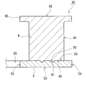
- FIG. 3 is a sectional view taken along the line III-III of FIG.
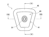
- FIG. 4 is a bottom view of the teeth provided on the stator of FIG.
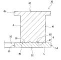
- FIG. 5A is a sectional view taken along line VV of FIG.
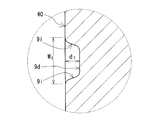
- FIG. 5B is an enlarged view of a circled portion in FIG. 5A.
- FIG. 6 is a sectional view taken along line VI-VI of FIG.
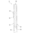
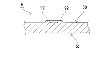
- FIG. 7 is a top view of a yoke provided in the stator of FIG.
- FIG. 8A is a sectional view taken along line VIII-VIII of FIG. FIG.
- FIG. 8B is an enlarged view of a portion circled in FIG. 8A.
- FIG. 9 is a sectional view taken along line IX-IX of FIG.
- FIG. 10 is a partial longitudinal sectional view of the axial gap type rotating electric machine according to the first embodiment.
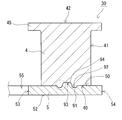
- FIG. 11 is a partial cross-sectional view illustrating a connection state between the teeth and the yoke of the rotating electric machine according to the second embodiment.
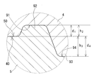
- FIG. 12A is a partial cross-sectional view illustrating a connection state between the teeth and the yoke of the rotating electric machine according to the third embodiment.
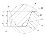
- FIG. 12B is an enlarged view of a circled portion in FIG. 12A.
- FIG. 13A is a partial cross-sectional view illustrating a connected state of the teeth and the yoke of the rotating electric machine according to the fourth embodiment.
- FIG. 13B is an enlarged view of a portion circled in FIG. 13A.
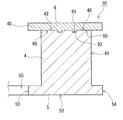
- FIG. 14 is a partial cross-sectional view illustrating a connection state between the teeth and the plate-shaped piece of the rotating electric machine according to the fifth embodiment.
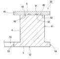
- FIG. 15 is a partial cross-sectional view illustrating a state of connection between the teeth and the plate-like piece of the rotating electric machine according to the sixth embodiment.
- One of the objects of the present disclosure is to provide a core of a green compact having high density overall and excellent productivity. Another object of the present disclosure is to provide a stator including the core. Further, another object of the present disclosure is to provide a rotating electric machine including the stator.
- the core of the present disclosure has high density overall and excellent productivity. Further, the stator of the present disclosure is excellent in magnetic properties and productivity. Further, the rotating electric machine according to the present disclosure is excellent in output characteristics and productivity.
- the teeth and the yoke may not be connected. Further, when producing a yoke having a concave portion by compression molding, it is difficult for the soft magnetic powder to spread to a portion which becomes an edge of the concave portion. Therefore, in order to manufacture a yoke having a concave portion, it is necessary to perform compression molding for forming the entire shape of the yoke and then perform compression molding for completing the concave portion. That is, a yoke having a concave portion cannot be completed by a single compression molding. In view of these problems, the present inventors have found that the above problems can be solved by setting the shapes of the concave portions and the convex portions to specific shapes.
- the core according to the embodiment includes: A core provided in a rotor or a stator of an axial gap type rotating electric machine,
- the core includes a block-shaped first member and a plate-shaped second member formed of a green compact,
- the first member includes a first surface facing the second member, and a first connection portion formed on the first surface
- the second member includes a second surface facing the first surface, and a second connection portion formed on the second surface and connected to the first connection portion,
- One of the first connection portion and the second connection portion is a protrusion, the other is configured by a depression having a shape corresponding to the protrusion,
- the front shape of the first connection portion as viewed from a direction perpendicular to the first surface, and the front shape of the second connection portion as viewed from a direction perpendicular to the second surface are connected in a ring shape or a part. There is no intermittent ring shape.
- the core has a high density as a whole.
- the reason why the locally low-density portion is not formed in the core is that the front shapes of the projections and the dents forming the first connection portion and the second connection portion have a ring shape or an intermittent ring shape ( Hereinafter, both the ring shape and the intermittent ring shape may be simply referred to as a ring shape).
- a height difference is formed between the projection and the inner and outer portions of the ring shape of the projection. The height difference makes it easier for the soft magnetic powder to flow between the protrusion and the inner and outer portions that are lower than the protrusion during compression molding.
- the depression a ring shape
- a height difference can be formed between the depression and the inner and outer portions of the ring shape of the depression.
- the height difference makes it easier for the soft magnetic powder to flow between the depression and the inner and outer portions that are higher than the depression during compression molding. If the fluidity of the soft magnetic powder in the vicinity of the protrusions and depressions is improved, a decrease in the density in the vicinity can be suppressed.
- the above core is excellent in productivity.
- the soft magnetic powder around the projections and depressions has high fluidity during the compression molding of the core, and a high-density core can be manufactured as a whole by a single compression molding.
- the fluidity of the soft magnetic powder is high, the incidence of defective products having locally low density portions is reduced.
- the first member is a tooth
- the second member may be a yoke.
- the mold for manufacturing the core can be made simple. Therefore, it is easy to make the densities of the teeth and the yoke uniform.
- a plurality of teeth provided on the core can be manufactured with one mold. Therefore, the productivity of the core can be improved.
- the first member is a tooth having a flange
- the second member may be a yoke
- the first member is an integral body of the teeth and the yoke
- the second member is a plate-shaped piece different from the yoke
- the plate-shaped piece may be arranged on an end surface of the tooth opposite to the yoke, and may include a flange portion protruding from a contour line of the end surface.
- a flange on the end surface of the tooth makes it difficult for the coil disposed on the tooth to come off the tooth.
- the plate-shaped piece including the flange portion and the teeth as separate members, the flange portion can be formed after the coil is arranged on the teeth. Therefore, the coil can be easily arranged on the core.
- the first member is a tooth
- the second member is a yoke and a separate plate-shaped piece from the yoke
- the plate-shaped piece may be arranged on an end surface of the tooth opposite to the yoke, and may include a flange portion protruding from a contour line of the end surface.
- the teeth, the yoke, and the plate-shaped member having the flange are separate configurations. With this configuration, it is possible to suppress variations in the density of each member formed of the compact.
- the front shape of the first connection portion and the front shape of the second connection portion may be non-annular.
- the depth of the depression and the height of the protrusion may be 0.5 mm or more, and may be 30% or less of the smaller thickness of the first member and the second member. it can.
- the depth of the depression and the height of the projection By setting the depth of the depression and the height of the projection to 0.5 mm or more, the connection strength between the projection and the depression can be sufficiently ensured. Further, by setting the depth of the depression and the height of the projection to 30% or less of the smaller thickness of the first member and the second member, the fluidity of the soft magnetic powder during compression molding is reduced, and The load on the mold can be suppressed.
- the width of the depression and the width of the projection may be in a range of 0.5 mm to 10 mm.
- the width of the depression and the width of the projection By setting the width of the depression and the width of the projection to 0.5 mm or more, the connection strength between the projection and the depression can be sufficiently ensured. In particular, by setting the width of the projection to 1.0 mm or more, the mechanical strength of the projection can be sufficiently ensured. Further, by setting the width of the depression and the width of the projection to 10 mm or less, a decrease in the fluidity of the soft magnetic powder during compression molding can be suppressed.
- the first connection portion may be a depression, and the second connection portion may be a protrusion.
- the second member on which the second connecting portion is formed is plate-shaped. Therefore, the mechanical strength of the entire second member can be improved by using the second connecting portion as a protrusion.
- the first connecting portion may be a protrusion
- the second connecting portion may be a depression
- the second member on which the second connecting portion is formed is plate-shaped. Therefore, by making the second connecting portion a depression, the assembling workability is improved when the first member and the second member are bonded.
- the front shape of the first connecting portion, and the front shape of the second connecting portion is a race track shape, or any shape selected from triangles, rectangles, trapezoids, and rhombuses where each vertex is rounded. A certain form can be mentioned.
- the front shapes of the first connecting portion and the second connecting portion do not become too complicated. Therefore, the mechanical strength of the first connecting portion and the second connecting portion is not easily reduced. Further, the above configuration has an advantage that a mold for manufacturing the first member and the second member can be easily manufactured.
- ⁇ 14> As one mode of the core according to the embodiment, When the area of the first surface is 100%, the area inside the outer peripheral contour line of the first connecting portion is 10% or more and 80% or less, Assuming that the area of the second surface is 100%, a form in which the area inside the outer peripheral contour line of the second connecting portion is 10% or more and 80% or less can be given.
- the area of the first surface (second surface) is the plane area of the first surface (second surface) when the first surface (second surface) is viewed from the orthogonal direction. That is, the area of the first surface (second surface) includes the area inside the outer peripheral contour of the first connection portion (second connection portion). According to the above configuration, the connection between the first member including the first connection portion and the second member including the second connection portion can be strengthened.
- the first member includes a third connection portion formed inside the ring shape of the first connection portion on the first surface
- the second member includes a fourth connecting portion formed inside the annular shape of the second connecting portion on the second surface
- the third connecting portion has a shape protruding to the opposite side of the first connecting portion from the first surface, or has a depressed shape
- the said 4th connection part can have the form provided with the shape corresponding to the said 3rd connection part.
- the first member and the second member can be connected more firmly by connecting the third connection part and the fourth connection part.
- the stator according to the embodiment includes: Any one of the above ⁇ 1> to ⁇ 15>, And a coil disposed on each tooth of the core.
- the above stator has excellent magnetic properties. This is because the core provided in the stator is the high-density core according to the embodiment. Further, the stator is excellent in productivity. This is because the core provided in the stator is a core according to the embodiment that is excellent in productivity.
- the rotating electric machine according to the embodiment includes: A rotor and a stator are axial gap type rotating electrical machines arranged in the axial direction of the rotating shaft of the rotor, This is the stator of the above item ⁇ 16>.
- the rotating electrical machine has excellent output characteristics. This is because the stator provided in the rotating electric machine is a stator having excellent magnetic characteristics. Further, the rotating electric machine is excellent in productivity. This is because the stator provided in the rotating electric machine is a stator excellent in productivity.
- the rotating electric machine 1 may be a generator or an electric motor (motor).
- the rotating electric machine 1 includes a rotor 2 and a stator 3 arranged in a housing 10.
- Rotor The rotor 2 includes a plurality of plate-shaped magnets 22 and an annular holding plate 21 that supports the magnets 22.
- the holding plate 21 is fixed to the shaft 20 and rotates together with the shaft 20.
- the magnet 22 is embedded in the holding plate 21.
- the magnets 22 are arranged at intervals in the circumferential direction of the shaft 20.
- the magnet 22 is magnetized in the rotation axis direction of the rotor 2 (axial direction of the shaft 20).
- the magnetization directions of the magnets 22 adjacent to each other in the circumferential direction of the shaft 20 are opposite to each other.
- the stator 3 includes the core 30 and the coils 31 arranged on the teeth 4 of the core 30.
- the stator 3 is arranged facing the rotor 2 in the axial direction of the shaft 20, and is fixed to the housing 10.
- a bearing 23 is arranged between the stator 3 and the shaft 20, and the stator 3 does not rotate.
- the rotating electric machine 1 of the present embodiment is characterized by the stator 3, particularly, a core 30 provided on the stator 3.
- the core 30 shown in FIGS. 1 to 3 includes the teeth 4 and the yoke 5.
- twelve teeth 4 are formed on the core 30.
- the number of the teeth 4 is not particularly limited. In the case of the axial gap type rotating electric machine 1, the number of the teeth 4 is preferably 2n (n is a natural number) in order to form a magnetic circuit via the yoke 5 with two adjacent teeth 4.
- the teeth 4 are formed as a block-shaped first member
- the yoke 5 is formed as a plate-shaped second member
- the teeth 4 and the yoke 5 are separately manufactured.
- the separately manufactured teeth 4 and yoke 5 are connected by a connecting mechanism 9 shown in FIG. Details of the coupling mechanism 9 will be described later.
- FIG. 4 In describing the teeth (first member) 4, mainly refer to FIGS. 4, 5A, 5B and 6.
- FIG. The tooth 4 of this example is a substantially trapezoidal columnar member having a flange (flange 45) at the end opposite to the yoke 5 (FIG. 3).
- the shape of the teeth 4 is not particularly limited.
- the teeth 4 may have a substantially triangular prism shape.
- the shape of the teeth 4 may be a columnar shape, a square columnar shape, or the like.
- the teeth 4 include a first surface 40, a peripheral surface 41, and an end surface 42.
- the first surface 40 is a flat surface and is a lower surface of the teeth 4 facing the yoke 5 (FIG. 3).
- the end surface 42 is the upper surface of the tooth 4 on the side opposite to the first surface 40.
- the peripheral surface 41 is a surface that connects the first surface 40 and the end surface 42.
- a first connecting portion 91 of the connecting mechanism 9 described below is formed on the first surface 40 of the tooth 4.
- the collar 45 provided on the teeth 4 may be omitted.
- the outer peripheral contour of the flange 45 in this example is substantially similar to the outer peripheral contour of the first surface 40.
- the flange portion 45 also has a role of preventing the coil 31 arranged on the teeth 4 from coming off the teeth 4.
- Teeth 4 is a green compact formed by compression molding soft magnetic powder.
- Soft magnetic powder is an aggregate of soft magnetic particles.
- the soft magnetic powder include pure iron (purity of 99% by mass or more), Fe—Si—Al alloy (Sendust), Fe—Si alloy (silicon steel), Fe—Al alloy, Fe—Ni At least one kind of powder selected from iron-based alloys such as a base alloy (Permalloy) is included.
- the soft magnetic particles preferably have an insulating coating on the surface. Since the insulating coating is formed on the surface of the soft magnetic particles, electrical insulation between the soft magnetic particles can be ensured. Therefore, iron loss of the teeth 4 due to eddy current loss can be reduced.
- the insulating coating include a phosphate coating and a silica coating.
- the average particle size of the soft magnetic particles is preferably 10 ⁇ m or more and 300 ⁇ m or less.
- the more preferable average particle size of the soft magnetic particles is 40 ⁇ m or more and 260 ⁇ m or less.
- the average particle diameter refers to the particle diameter of a particle in which the sum of the masses of particles having a small particle diameter reaches 50% of the total mass in the histogram of the particle diameters, that is, the 50% particle diameter.
- the relative density of the green compact is preferably 90% or more, and the magnetic properties of the green compact can be improved by increasing the density.
- a more preferable relative density is 93% or more.
- the relative density is a ratio (%) of the density of the green compact to the true density of the green compact (soft magnetic powder).
- the yoke 5 is an annular member.
- the yoke 5 of this example is formed of one member.
- the yoke 5 can also be configured by combining a plurality of divided pieces.
- the circular yoke 5 can be formed by joining the fan-shaped divided pieces.
- the yoke 5 includes a second surface 50, a back surface 52, an inner edge surface 53, and an outer edge surface 54.
- the second surface 50 is a surface facing the first surface 40 as shown in FIG.
- the second surface 50 is a flat surface parallel to the first surface 40. Therefore, the entire surface of the first surface 40 of the tooth 4 comes into surface contact with the second surface 50.
- the back surface 52 of the yoke 5 is the lower surface of the yoke 5 parallel to the second surface 50.
- the edge surface 53 is a surface that connects the second surface 50 and the back surface 52 inside the ring of the yoke 5. Inside the edge surface 53, a through hole 55 is formed to penetrate the shaft 20 (FIG. 10).
- the edge surface 54 is a surface that connects the second surface 50 and the back surface 52 outside the ring of the yoke 5.
- On the second surface 50 of the yoke 5, a second connecting portion 92 of the connecting mechanism 9 described later is formed.
- the yoke 5 is formed of a powder compact similarly to the teeth 4.
- the composition of the green compact forming the yoke 5 may be the same as or different from the composition of the green compact forming the teeth 4.
- the density of the yoke 5 may be the same as or different from the density of the teeth 4.
- connection mechanism 9 includes a first connection portion 91 and a second connection portion 92.
- the first connecting portion 91 is a depression formed on the first surface 40
- the second connecting portion 92 is a projection projecting from the second surface 50.
- the inner shape of the first connecting portion 91 (dent) has a shape corresponding to the outer shape of the second connecting portion 92 (projection). Therefore, by fitting the second connecting portion 92 into the first connecting portion 91, the outer peripheral surface of the second connecting portion 92 comes into surface contact with the inner peripheral surface of the first connecting portion 91. As a result, the teeth 4 and the yoke 5 are connected.
- First connecting portion The shape of the first connecting portion 91 (dent) will be described in detail with reference to FIGS. 4, 5A and 5B.
- the front shape of the first connecting portion 91 as viewed from a direction orthogonal to the first surface 40 is a ring shape.
- the front shape of the first connecting portion 91 of this example is a race track shape.
- the front shape of the first connecting portion 91 may be an annular shape or a non-annular shape including the race track shape of the present example.
- Non-annular shapes other than the racetrack shape include, for example, polygons such as triangles, rectangles (including squares), trapezoids, or rhombuses with rounded vertices, and C-shapes or U-shapes where parts of the rings are not connected. And an intermittent ring shape. If the front shape of the first connecting portion 91 is non-annular, after the teeth 4 and the yoke 5 are connected, the teeth 4 rotate on the first surface 40 (the second surface 50) with respect to the yoke 5. Can be suppressed. Unlike the example of FIG. 4, when the first connecting portion 91 is bisected into the radially inner side and the outer side of the yoke 5 (FIG.
- the paper surface sandwiching the dividing line (see the two-dot chain line in FIG.
- the upper part and the lower part may be non-linearly symmetric. In this case, the direction of the teeth 4 with respect to the yoke 5 is limited, so that the direction of the teeth 4 is not mistaken.
- the inside of the ring shape of the first connecting portion 91 (dent) is at the same height as the first surface 40. Unlike this example, the inside of the ring shape of the first connecting portion 91 may be recessed from the first surface 40, or may protrude from the first surface 40 as in a third embodiment described later.
- the number of the first connecting portions 91 in the teeth 4 is one.
- a plurality of first connecting portions 91 can be provided in one tooth 4.
- a part may be depressed and the rest may be formed as projections.
- the width of the first connecting portion 91 (dent) of the present example is gradually narrowed in the depth direction. That is, the width of the bottom surface 9d of the first connecting portion 91 is smaller than the width of the opening of the first connecting portion 91. Further, the inner wall surface 9i is inclined in a direction that expands from the bottom surface 9d toward the opening.
- the depression having such a shape contributes to improving the fluidity of the soft magnetic powder during compression molding. Of course, the depression may have a uniform width in the depth direction.
- the width of the first connecting portion 91 refers to a length in a direction orthogonal to the circumferential direction of the ring shape of the first connecting portion 91 (the thickness direction of the paper surface of FIG. 5B).
- the joint between the bottom surface 9d and the inner wall surface 9i in the first connecting portion 91 (dent) is rounded.
- the joint between the inner wall surface 9i and the first surface 40 is rounded.
- the radius of curvature of the roundness can be 0.5 mm or more and 4.0 mm or less.
- a more preferable radius of curvature is 1.0 mm or more and 3.0 mm or less.
- Width w 1 of the first connection portion 91 is preferably set to 0.5mm or more 10mm or less.
- Width w 1 is the width of the opening of the recess. By setting the width w 1 or more 0.5 mm, it can be sufficiently secured first connection portion 91 (the recess) coupling strength between the second connection portion 92 (projection). Further, by setting the width w 1 and 10mm or less, a decrease in the flowability of the soft magnetic powder at the time of compression molding can be suppressed. More preferably the width w 1 is 0.5mm or more 4mm or less, further preferable that the width w 1 is less than 1.0mm 3.0mm or less.
- the depth d 1 of the first connection portion 91 is a 0.5mm or more, and among the first and second members, 30% of the thickness of the direction thickness is small (yoke 5 in this embodiment) or less and Is preferred.
- the depth d 1 is the length of a perpendicular from the first surface 40 to the bottom surface 9d.
- the depth d 1 by a least 0.5 mm can be sufficiently secured first connection portion 91 (the recess) coupling strength between the second connection portion 92 (projection).
- the depth d 1 is set to lower than or equal to 30% of the thickness of the yoke 5, a reduction in the flowability of the soft magnetic powder at the time of compression molding can be suppressed. More preferably a depth d 1 is a 1.0mm or more, and among the first and second members, more than 25% of the thickness of the direction thickness is small.
- the size of the outer peripheral contour line (see FIG. 4) of the first connecting portion 91 on the first surface 40 can be appropriately selected.
- the area inside the outer peripheral contour line of the first connecting portion 91 can be 10% or more and 80% or less.
- the area ratio of the outer shape of the first connecting portion 91 to the first surface 40 is 10% or more and 80% or less, the connection between the teeth 4 and the yoke 5 can be strengthened.
- a more preferable area ratio is 20% or more and 70% or less.
- Second connecting portion The shape of the second connecting portion 92 (projection) will be described in detail with reference to FIGS. As described above, the second connecting portion 92 has a shape corresponding to the first connecting portion 91. Therefore, as shown in FIG. 7, the front shape of the second connecting portion 92 viewed from a direction orthogonal to the second surface 50 is the same shape and size as the front shape of the first connecting portion 91.
- the inside of the ring shape of the second connecting portion 92 is at the same height as the second surface 50. Unlike this example, the inside of the ring shape of the second connecting portion 92 may protrude from the second surface 50, or may be depressed from the second surface 50 as in a fourth embodiment described later. .
- the width of the second connecting portion 92 (projection) in this example is gradually reduced toward the top surface 9t. That is, the width of the top surface 9t of the second connecting portion 92 is smaller than the width of the root of the second connecting portion 92. Further, the outer wall surface 9o is inclined in a direction to become narrower from the base toward the top surface 9t. The projection having such a shape contributes to improving the fluidity of the soft magnetic powder during compression molding.
- the width of the second connecting portion 92 is a length orthogonal to the circumferential direction of the ring shape of the second connecting portion 92 (the thickness direction of the paper surface of FIG. 8B).
- the joint between the top surface 9t and the outer wall surface 9o and the joint between the outer wall surface 9o and the second surface 50 in the second connecting portion 92 (projection) are rounded according to the shape of the first connecting portion 91 (dent). Have been. By rounding both joints of the projections, the fluidity of the soft magnetic powder during compression molding can be improved.
- Width w 2 of the second connection portion 92 (projection) is the same as the width w 1 of the first connection portion 91 (recess) in Figure 5B. Width w 2 is the width of the root of the protrusion.
- the height h 2 of the second connection portion 92 (projection) is the same as the depth d 1 of the first connection portion 91 (recess) in Figure 5B.
- the height h 2 is the length of the perpendicular line from the extension plane of the second surface 50 to the top surface 9t.
- Limited width w 2 and height h 2 of the protrusions contribute to improvement of the mechanical strength of the protrusion. Also, limiting the width w 2 and height h 2 of the protrusions contribute to improvement of the flowability of the soft magnetic powder in the vicinity of the projection during compression molding.
- the core 30 (FIG. 1) of the embodiment hardly has a locally low density portion of the soft magnetic powder, the core 30 has a high density as a whole.
- the reason why the locally low-density portion is not formed in the core 30 is that the front shapes of the projections and depressions forming the first connecting portion 91 and the second connecting portion 92 have a ring shape or an intermittent ring shape. It is.
- the core 30 of the embodiment is excellent in productivity. This is because the fluidity of the soft magnetic powder around the projections and depressions during the compression molding of the core 30 is high, and the core 30 having a high density can be manufactured as a whole by a single compression molding. In addition, since the soft magnetic powder has high fluidity, the rate of occurrence of defective products having locally low-density portions is also reduced, which is a factor that improves the productivity of the core 30.
- the teeth 4 and the yoke 5 are separate members.
- a mold for manufacturing the core 30 can have a simple shape. As a result, it is easy to make the densities of the teeth 4 and the yoke 5 uniform. Further, a plurality of teeth 4 provided on the core 30 can be manufactured by one mold. As a result, the productivity of the core 30 can be improved.
- the second connecting portion 92 formed on the yoke 5 is a projection. Therefore, a decrease in mechanical strength of the yoke 5 due to the provision of the second connecting portion 92 can be suppressed.
- the stator 3 (FIG. 10) including the core 30 of the above embodiment has excellent magnetic properties. This is because the density of the magnetic powder of the stator 3 is high. Moreover, the stator 3 is excellent in productivity. This is because the productivity of the core 30 provided in the stator 3 is high.
- the rotating electric machine 1 including the stator 3 of the above embodiment has excellent output characteristics. This is because the magnetic characteristics of the stator 3 provided in the rotating electric machine 1 are high. Further, the rotating electric machine 1 is excellent in productivity. This is because the productivity of the stator 3 provided in the rotating electric machine 1 is high.
- the first connecting portion 91 of the tooth 4 is a projection
- the second connecting portion 92 of the yoke 5 is a depression.
- the shapes and dimensions of the protrusions and depressions can be the same as those in the first embodiment. According to the configuration of this example, the same effect as that of the first embodiment can be obtained.
- the third connecting portion 93 is a projection formed on the first surface 40 inside the ring shape of the first connecting portion 91 and protruding from the first surface 40.
- the height h 3 of the third connecting portion 93 of this embodiment is larger than the height h 2 of the second connection portion 92 (projection).
- the height h 3 of the third connection portion 93 is a length of a perpendicular from the first surface 40 to the top surface of the projection.
- a preferred range of the height h 3 is the same as the preferred range of the height h 2.
- the fourth connection portion 94 is a recess formed on the second surface 50 inside the ring shape of the second connection portion 92 and lower than the second surface 50.
- the inner shape of the fourth connecting portion 94 (dent) has a shape corresponding to the outer shape of the third connecting portion 93 (projection). Therefore, as shown in FIG. 12B, the depth d 4 of the fourth connection portion 94 of the present embodiment (recess) is the same size as the height h 3 of the third connection portion 93 (projection).
- the teeth 4 and the yoke 5 can be connected more firmly than the core 30 of the first and second embodiments.
- the third connection portion 93 of the present example is a depression formed inside the ring shape of the first connection portion 91 on the first surface 40.
- the fourth connecting portion 94 is a protrusion formed inside the ring shape of the second connecting portion 92 on the second surface 50.
- the inner shape of the third connecting portion 93 (dent) has a shape corresponding to the outer shape of the fourth connecting portion 94 (projection). Therefore, as shown in FIG. 13B, the depth d 3 of the third connecting portion 93 of this embodiment are the same as the fourth connecting portion 94 the height h 4.
- the teeth 4 of the present example are formed integrally with the yoke 5. As in the core 30 of the first to fourth embodiments, the teeth 4 and the yoke 5 may be formed separately. In this case, although the number of components constituting the core 30 increases, the density of the entire core 30 can be easily made uniform.
- the plate-shaped piece 6 is provided on the end surface 42 of the tooth 4 opposite to the yoke. This plate-shaped piece 6 is produced separately from the teeth 4 and connected to the teeth 4. That is, the teeth 4 are the first member, and the plate-like pieces 6 are the second member.
- the end surface 42 of the tooth 4 (first member) is also the first surface 40 facing the plate-like piece 6 (second member).
- the opposing surface 60 of the plate-shaped piece 6 that opposes the first surface 40 is the second surface 50.
- a first connecting portion 91 formed of a ring-shaped depression is formed on the first surface 40 of the tooth 4. Further, on the second surface 50 of the plate-shaped piece 6, a second connecting portion 92 formed of a ring-shaped projection is formed.
- the flange 45 can be formed on the tooth 4. In this case, the arrangement of the coil 31 becomes very easy.
- a core 30 different from that of the fifth embodiment will be described with reference to FIG. 15 as a configuration including the plate-shaped piece 6 disposed on the side of the tooth 4 opposite to the yoke 5.
- the first surface 40 of the tooth 4 is provided with a first connecting portion 91 formed of a ring-shaped projection.
- the second surface 50 of the plate-shaped piece 6 has a second connecting portion 92 formed of a ring-shaped depression.
- the flange 45 can be formed on the tooth 4.
- the core 30 described in the first to sixth embodiments is used for a stator. This core can also be used for a rotor.
- Reference Signs List 1 rotating electric machine 10 housing 2 rotor 20 shaft, 21 holding plate, 22 magnet, 23 bearing 3 stator 30 core, 31 coil 4 teeth (first member) 40 first surface, 41 peripheral surface, 42 end surface, 45 flange 5 yoke (second member) 50 second surface, 52 back surface, 53 inner edge surface, 54 outer edge surface, 55 through hole 6 plate-shaped piece (second member) 60 opposing surface 9 connecting mechanism 91 first connecting portion, 92 second connecting portion, 93 third connecting portion, 94 fourth connecting portion 9d bottom surface, 9i inner wall surface, 9o outer wall surface, 9t top surface
Landscapes
- Engineering & Computer Science (AREA)
- Power Engineering (AREA)
- Iron Core Of Rotating Electric Machines (AREA)
Abstract
Description
本出願は、2018年7月27日付の日本国出願の特願2018-141841に基づく優先権を主張し、前記日本国出願に記載された全ての記載内容を援用するものである。
アキシャルギャップ型の回転電機のロータ又はステータに備わるコアであって、
前記コアは、圧粉成形体で構成されるブロック状の第一部材及び板状の第二部材を備え、
前記第一部材は、前記第二部材に対向する第一面と、前記第一面に形成される第一連結部とを備え、
前記第二部材は、前記第一面に対向する第二面と、前記第二面に形成され、前記第一連結部に連結する第二連結部とを備え、
前記第一連結部及び前記第二連結部の一方が突起、他方が前記突起に対応する形状を有する窪みで構成されており、
前記第一連結部を前記第一面に直交する方向から見た正面形状、及び前記第二連結部を前記第二面に直交する方向から見た正面形状が、環形状又は一部が繋がっていない断続的な環形状である。
本開示のコアと、
前記コアに備わる各ティースに配置されるコイルとを備える。
ロータとステータとが、前記ロータの回転軸の軸方向に並ぶアキシャルギャップ型の回転電機であって、
前記ステータが本開示のステータである。
コアの磁気特性を向上させ、かつコアの生産性を向上させることが望まれている。そのためには、ヨークとティースの両方を高密度の圧粉成形体で構成することが有効と考えられる。圧粉成形体を高密度化するには、高い成形圧(面圧)で軟磁性粉末を圧縮成形する必要がある。しかし、本発明者らの検討によれば、特許文献1に記載される形状のヨークとティースでは、部分的に密度が低い部分ができ易いことが分かった。また、特許文献1に記載される形状のヨークとティースは、一度の圧縮成形で完成させられない場合があることも分かった。
本開示のコアは、全体的に高密度で、生産性に優れる。また、本開示のステータは、磁気特性と生産性に優れる。更に、本開示の回転電機は、出力特性と生産性に優れる。
本発明者らは、ブロック状のティースと板状のヨークとを各々、圧粉成形体で形成する際の問題点を検討した。その結果、ティースとヨークとを連結させる凹部と凸部が特許文献1に記載されるような単純な形状であることが問題となることが分かった。圧縮成形で凸部を有するティースを作製する場合、凸部の角となる部分に軟磁性粉末が行き渡り難く、凸部(特に凸部の角)の密度が他の部分よりも低くなり易い。凸部の密度が低いと、凸部の強度が低下し、凸部が破損し易くなる。そのため、ティースとヨークとを連結できなくなる恐れがある。また、圧縮成形で凹部を有するヨークを作製する場合、凹部の縁となる部分に軟磁性粉末が行き渡り難い。そのため、凹部を有するヨークを作製するには、ヨークの全体形状を形成する圧縮成形を行った後、更に凹部を完成させるための圧縮成形を行わなければならない。つまり、一度の圧縮成形で凹部を有するヨークを完成させることができない。これらの問題点を踏まえて本発明者らは、凹部と凸部の形状を特定の形状とすることで上記問題点を解決できることを見出した。
アキシャルギャップ型の回転電機のロータ又はステータに備わるコアであって、
前記コアは、圧粉成形体で構成されるブロック状の第一部材及び板状の第二部材を備え、
前記第一部材は、前記第二部材に対向する第一面と、前記第一面に形成される第一連結部とを備え、
前記第二部材は、前記第一面に対向する第二面と、前記第二面に形成され、前記第一連結部に連結する第二連結部とを備え、
前記第一連結部及び前記第二連結部の一方が突起、他方が前記突起に対応する形状を有する窪みで構成されており、
前記第一連結部を前記第一面に直交する方向から見た正面形状、及び前記第二連結部を前記第二面に直交する方向から見た正面形状が、環形状又は一部が繋がっていない断続的な環形状である。
前記第一部材はティースであり、
前記第二部材はヨークである形態を挙げることができる。
前記第一部材は鍔部を有するティースであり、
前記第二部材はヨークである形態を挙げることができる。
前記第一部材はティースとヨークとの一体物であり、
前記第二部材は前記ヨークとは別の板状片であり、
前記板状片は、前記ティースにおける前記ヨークとは反対側の端面に配置され、前記端面の輪郭線からはみ出す鍔部を備える形態を挙げることができる。
前記第一部材はティースであり、
前記第二部材はヨーク及び前記ヨークとは別の板状片であり、
前記板状片は、前記ティースにおける前記ヨークとは反対側の端面に配置され、前記端面の輪郭線からはみ出す鍔部を備える形態を挙げることができる。
前記第一連結部の前記正面形状、及び前記第二連結部の前記正面形状が、非円環形状である形態を挙げることができる。
前記窪みにおける底面と内壁面との繋ぎ目、及び前記内壁面と前記第一面又は第二面との繋ぎ目が丸められており、
前記突起における頂面と外壁面との繋ぎ目、及び前記外壁面と前記第一面又は第二面との繋ぎ目が丸められている形態を挙げることができる。
前記窪みの深さ、及び前記突起の高さは、0.5mm以上で、かつ前記第一部材と前記第二部材のうち、厚みが小さい方の厚みの30%以下である形態を挙げることができる。
前記窪みの幅、及び前記突起の幅は、0.5mm以上10mm以下である形態を挙げることができる。
前記窪みにおける底面と内壁面との繋ぎ目、及び前記内壁面と前記第一面又は前記第二面との繋ぎ目、並びに
前記突起における頂面と外壁面との繋ぎ目、及び前記外壁面と前記第一面又は前記第二面との繋ぎ目が丸められており、
前記各繋ぎ目の丸みの曲率半径が0.5mm以上4.0mm以下である形態を挙げることができる。
前記第一連結部は窪みで、前記第二連結部は突起である形態を挙げることができる。
前記第一連結部は突起で、前記第二連結部は窪みである形態を挙げることができる。
前記第一連結部の前記正面形状、及び前記第二連結部の前記正面形状が、レーストラック形状、又は各頂点が丸められた三角形、長方形、台形、及び菱形から選択されるいずれかの形状である形態を挙げることができる。
前記第一面の面積を100%としたとき、前記第一連結部の外周輪郭線よりも内側の面積が10%以上80%以下、
前記第二面の面積を100%としたとき、前記第二連結部の外周輪郭線よりも内側の面積が10%以上80%以下である形態を挙げることができる。
前記第一部材は、前記第一面における前記第一連結部の環形状の内側に形成される第三連結部を備え、
前記第二部材は、前記第二面における前記第二連結部の環形状の内側に形成される第四連結部を備え、
前記第三連結部は、前記第一面よりも前記第一連結部の反対側に突出する形状、又は窪んだ形状を備え、
前記第四連結部は、前記第三連結部に対応する形状を備える形態を挙げることができる。
上記<1>から<15>のいずれかのコアと、
前記コアに備わる各ティースに配置されるコイルとを備える。
ロータとステータとが、前記ロータの回転軸の軸方向に並ぶアキシャルギャップ型の回転電機であって、
上記<16>のステータである。
本開示の実施形態に係るコア、ステータ、及び回転電機の具体例を図面に基づいて説明する。図中の同一符号は同一又は相当部分を示す。なお、本発明はこれらの例示に限定されるものではなく、請求の範囲によって示され、請求の範囲と均等の意味および範囲内でのすべての変更が含まれることが意図される。
≪回転電機≫
実施形態1では、図10に示すアキシャルギャップ型の回転電機1を例にして説明を行う。回転電機1は、発電機でも良いし、電動機(モータ)でも良い。回転電機1は、ハウジング10内に配置されるロータ2とステータ3とを備える。
ロータ2は、平板状の複数の磁石22と、これら磁石22を支持する円環形状の保持板21とを備える。保持板21は、シャフト20に固定され、シャフト20と共に回転する。磁石22は保持板21に埋め込まれている。磁石22は、シャフト20の周方向に間隔をあけて配置されている。また、磁石22は、ロータ2の回転軸方向(シャフト20の軸方向)に着磁されている。シャフト20の周方向に隣り合う磁石22の磁化方向は互いに逆になっている。
ステータ3は、コア30と、コア30のティース4に配置されるコイル31とを備える。ステータ3は、シャフト20の軸方向にロータ2に対向して配置され、ハウジング10に固定されている。ステータ3とシャフト20との間には軸受23が配置されており、ステータ3は回転しない。本実施形態の回転電機1は、このステータ3、特にステータ3に備わるコア30に特徴がある。
図1~3に示すコア30は、ティース4とヨーク5とを備える。本例では、コア30に12個のティース4が形成されている。ティース4の数は特に限定されない。アキシャルギャップ型の回転電機1の場合、隣り合う2個のティース4でヨーク5を介した磁気回路を形成するため、ティース4の個数は2n(nは自然数)個とすることが好ましい。本例では、ティース4をブロック状の第一部材とし、ヨーク5を板状の第二部材とし、ティース4とヨーク5とを別個に作製する。別個に作製したティース4とヨーク5は、図3に示す連結機構9によって連結される。連結機構9の詳細は後述する。
ティース(第一部材)4の説明にあたっては、主として図4,5A,5B,6を参照する。本例のティース4は、ヨーク5(図3)とは反対側の端部にフランジ(鍔部45)を有する概略台形柱状の部材である。ティース4の形状は特に限定されない。例えば、ティース4は概略三角柱状であっても構わない。その他、ティース4の形状は、円柱状や四角柱状などでも良い。
ヨーク5の説明にあたっては主として図7,8A,8B,9を参照する。図7に示すように、ヨーク5は円環形状の部材である。本例のヨーク5は一つの部材で構成されている。ヨーク5は複数の分割片を組み合わせて構成することもできる。例えば、扇状の分割片を繋ぎ合わせて円環形状のヨーク5を形成できる。
連結機構9は、第一連結部91と第二連結部92とを備える。第一連結部91は、第一面40に形成される窪みであり、第二連結部92は、第二面50から突出する突起である。第一連結部91(窪み)の内形は、第二連結部92(突起)の外形に対応する形状となっている。そのため、第一連結部91に第二連結部92を嵌め込むことで、第一連結部91の内周面に第二連結部92の外周面が面接触する。その結果、ティース4とヨーク5とが連結される。
図4,5A,5Bに基づいて、第一連結部91(窪み)の形状を詳しく説明する。図4に示すように、第一連結部91を第一面40と直交する方向から見た正面形状は環形状になっている。本例の第一連結部91の正面形状は、レーストラック形状となっている。第一連結部91の正面形状は、円環形状であっても良いし、本例のレーストラック形状を含む非円環形状であっても良い。レーストラック形状以外の非円環形状としては、例えば各頂点が丸められた三角形、長方形(正方形を含む)、台形、又は菱形などの多角形状、環の一部が繋がっていないC字形やU字形などの断続的な環形状を挙げることができる。第一連結部91の正面形状が非円環形状であれば、ティース4とヨーク5とを連結した後、第一面40(第二面50)上で、ティース4がヨーク5に対して回転することを抑制できる。図4の例示とは異なり、第一連結部91をヨーク5(図1)の径方向の内方側と外方側に二分したとき、分割線(図4の二点鎖線参照)を挟む紙面上側の部分と下側の部分とが非線対称となっても良い。その場合、ヨーク5に対するティース4の向きが限定されるので、ティース4の向きを間違えることが無くなる。
図7,8に基づいて、第二連結部92(突起)の形状を詳しく説明する。既に述べたように、第二連結部92は、第一連結部91に対応する形状を備えている。そのため、図7に示すように、第二連結部92を第二面50と直交する方向から見た正面形状は、第一連結部91の正面形状と同じ形状・同じ大きさとなっている。
実施形態のコア30(図1)には局所的に軟磁性粉末の密度が低い箇所が殆ど無いため、コア30は全体的に高密度である。局所的に低密度な箇所がコア30に形成されないのは、第一連結部91と第二連結部92を構成する突起と窪みの正面形状が環形状又は断続的な環形状となっているからである。
実施形態2では、実施形態1とは異なるコア30を図11に基づいて説明する。図11の見方は実施形態1の図3と同じである。
実施形態3では、ティース4が第三連結部93を有し、ヨーク5が第四連結部94を有するコア30を図12A,12Bに基づいて説明する。
実施形態4では、実施形態3と異なるコア30を図13A,13Bに基づいて説明する。
実施形態5では、ティース4と、ティース4におけるヨーク5とは反対側に配置される板状片6と、を連結したコア30を図14に基づいて説明する。
ティース4におけるヨーク5とは反対側に配置される板状片6を備える構成として、実施形態6では、実施形態5とは異なるコア30を図15に基づいて説明する。
実施形態1~6で説明したコア30は、ステータに用いられるものである。このコアは、ロータに用いることもできる。
10 ハウジング
2 ロータ
20 シャフト、21 保持板、22 磁石、23 軸受
3 ステータ
30 コア、31 コイル
4 ティース(第一部材)
40 第一面、41 周面、42 端面、45 鍔部
5 ヨーク(第二部材)
50 第二面、52 裏面、53 内側の縁面、54 外側の縁面、55 貫通孔
6 板状片(第二部材)
60 対向面
9 連結機構
91 第一連結部、92 第二連結部、93 第三連結部、94 第四連結部
9d 底面、9i 内壁面、9o 外壁面、9t 頂面
Claims (17)
- アキシャルギャップ型の回転電機のロータ又はステータに備わるコアであって、
前記コアは、圧粉成形体で構成されるブロック状の第一部材及び板状の第二部材を備え、
前記第一部材は、前記第二部材に対向する第一面と、前記第一面に形成される第一連結部とを備え、
前記第二部材は、前記第一面に対向する第二面と、前記第二面に形成され、前記第一連結部に連結する第二連結部とを備え、
前記第一連結部及び前記第二連結部の一方が突起、他方が前記突起に対応する形状を有する窪みで構成されており、
前記第一連結部を前記第一面に直交する方向から見た正面形状、及び前記第二連結部を前記第二面に直交する方向から見た正面形状が、環形状又は一部が繋がっていない断続的な環形状である、
コア。 - 前記第一部材はティースであり、
前記第二部材はヨークである請求項1に記載のコア。 - 前記第一部材は鍔部を有するティースであり、
前記第二部材はヨークである請求項1に記載のコア。 - 前記第一部材はティースとヨークとの一体物であり、
前記第二部材は前記ヨークとは別の板状片であり、
前記板状片は、前記ティースにおける前記ヨークとは反対側の端面に配置され、前記端面の輪郭線からはみ出す鍔部を備える請求項1に記載のコア。 - 前記第一部材はティースであり、
前記第二部材はヨーク及び前記ヨークとは別の板状片であり、
前記板状片は、前記ティースにおける前記ヨークとは反対側の端面に配置され、前記端面の輪郭線からはみ出す鍔部を備える請求項1に記載のコア。 - 前記第一連結部の前記正面形状、及び前記第二連結部の前記正面形状が、非円環形状である請求項1から請求項5のいずれか1項に記載のコア。
- 前記窪みにおける底面と内壁面との繋ぎ目、及び前記内壁面と前記第一面又は第二面との繋ぎ目が丸められており、
前記突起における頂面と外壁面との繋ぎ目、及び前記外壁面と前記第一面又は第二面との繋ぎ目が丸められている請求項1から請求項6のいずれか1項に記載のコア。 - 前記窪みの深さ、及び前記突起の高さは、0.5mm以上で、かつ前記第一部材と前記第二部材のうち、厚みが小さい方の厚みの30%以下である請求項1から請求項7のいずれか1項に記載のコア。
- 前記窪みの幅、及び前記突起の幅は、0.5mm以上10mm以下である請求項1から請求項8のいずれか1項に記載のコア。
- 前記窪みにおける底面と内壁面との繋ぎ目、及び前記内壁面と前記第一面又は前記第二面との繋ぎ目、並びに
前記突起における頂面と外壁面との繋ぎ目、及び前記外壁面と前記第一面又は前記第二面との繋ぎ目が丸められており、
前記各繋ぎ目の丸みの曲率半径が0.5mm以上4.0mm以下である請求項1から請求項9のいずれか1項に記載のコア。 - 前記第一連結部は窪みで、前記第二連結部は突起である請求項1から請求項10のいずれか1項に記載のコア。
- 前記第一連結部は突起で、前記第二連結部は窪みである請求項1から請求項10のいずれか1項に記載のコア。
- 前記第一連結部の前記正面形状、及び前記第二連結部の前記正面形状が、レーストラック形状、又は各頂点が丸められた三角形、長方形、台形、及び菱形から選択されるいずれかの形状である請求項1から請求項12のいずれか1項に記載のコア。
- 前記第一面の面積を100%としたとき、前記第一連結部の外周輪郭線よりも内側の面積が10%以上80%以下、
前記第二面の面積を100%としたとき、前記第二連結部の外周輪郭線よりも内側の面積が10%以上80%以下である請求項1から請求項13のいずれか1項に記載のコア。 - 前記第一部材は、前記第一面における前記第一連結部の環形状の内側に形成される第三連結部を備え、
前記第二部材は、前記第二面における前記第二連結部の環形状の内側に形成される第四連結部を備え、
前記第三連結部は、前記第一面よりも前記第一連結部の反対側に突出する形状、又は窪んだ形状を備え、
前記第四連結部は、前記第三連結部に対応する形状を備える請求項1から請求項14のいずれか1項に記載のコア。 - 請求項1から請求項15のいずれか1項に記載のコアと、
前記コアに備わる各ティースに配置されるコイルとを備える、
ステータ。 - ロータとステータとが、前記ロータの回転軸の軸方向に並ぶアキシャルギャップ型の回転電機であって、
前記ステータが請求項16に記載のステータである、
回転電機。
Priority Applications (4)
| Application Number | Priority Date | Filing Date | Title |
|---|---|---|---|
| JP2020532293A JP7319274B2 (ja) | 2018-07-27 | 2019-07-11 | コア、ステータ、及び回転電機 |
| US17/258,546 US11770034B2 (en) | 2018-07-27 | 2019-07-11 | Core for, rotating electrical machine |
| CN201980044993.3A CN112385118B (zh) | 2018-07-27 | 2019-07-11 | 铁芯、定子及旋转电机 |
| DE112019003800.1T DE112019003800T5 (de) | 2018-07-27 | 2019-07-11 | Kern, stator, und rotierende elektrische maschine |
Applications Claiming Priority (2)
| Application Number | Priority Date | Filing Date | Title |
|---|---|---|---|
| JP2018-141841 | 2018-07-27 | ||
| JP2018141841 | 2018-07-27 |
Publications (1)
| Publication Number | Publication Date |
|---|---|
| WO2020022094A1 true WO2020022094A1 (ja) | 2020-01-30 |
Family
ID=69181692
Family Applications (1)
| Application Number | Title | Priority Date | Filing Date |
|---|---|---|---|
| PCT/JP2019/027594 Ceased WO2020022094A1 (ja) | 2018-07-27 | 2019-07-11 | コア、ステータ、及び回転電機 |
Country Status (5)
| Country | Link |
|---|---|
| US (1) | US11770034B2 (ja) |
| JP (1) | JP7319274B2 (ja) |
| CN (1) | CN112385118B (ja) |
| DE (1) | DE112019003800T5 (ja) |
| WO (1) | WO2020022094A1 (ja) |
Cited By (1)
| Publication number | Priority date | Publication date | Assignee | Title |
|---|---|---|---|---|
| EP4071971A1 (en) * | 2021-04-05 | 2022-10-12 | Yoshiki Hirai | Axial gap motor stator core and axial gap motor stator core manufacturing method |
Families Citing this family (1)
| Publication number | Priority date | Publication date | Assignee | Title |
|---|---|---|---|---|
| JP7195920B2 (ja) * | 2018-12-27 | 2022-12-26 | 住友電気工業株式会社 | コア、ステータ、及び回転電機 |
Citations (5)
| Publication number | Priority date | Publication date | Assignee | Title |
|---|---|---|---|---|
| JP3009745U (ja) * | 1994-09-30 | 1995-04-11 | 丸富漆器株式会社 | 飾花用具 |
| JPH07164156A (ja) * | 1993-12-15 | 1995-06-27 | Mitsubishi Materials Corp | 金属焼結部材の接合方法 |
| JP2003079120A (ja) * | 2001-09-03 | 2003-03-14 | Asmo Co Ltd | モータ用コア及び直流モータ |
| JP2011091933A (ja) * | 2009-10-22 | 2011-05-06 | Hitachi Industrial Equipment Systems Co Ltd | アキシャルギャップモータ、圧縮機、モータシステム、および発電機 |
| JP2017093707A (ja) * | 2015-11-20 | 2017-06-01 | コクヨ株式会社 | パネル支持脚 |
Family Cites Families (5)
| Publication number | Priority date | Publication date | Assignee | Title |
|---|---|---|---|---|
| JP2001112211A (ja) * | 1999-10-08 | 2001-04-20 | Sankyo Seiki Mfg Co Ltd | 小型モータ |
| FR2851088B1 (fr) * | 2003-02-12 | 2006-01-27 | Seb Sa | Stator pour moteur electrique a flux axial |
| EP2022983A3 (en) | 2006-03-27 | 2017-09-06 | Daikin Industries, Ltd. | Armature core, motor using it, and its manufacturing method |
| CN103312091B (zh) * | 2012-03-07 | 2017-12-19 | 博世汽车部件(长沙)有限公司 | 用于电动调节车辆中的活动部件的电机以及用于制造电机的方法 |
| EP4397403A3 (en) * | 2016-03-31 | 2024-10-23 | Global Life Sciences Solutions USA LLC | Magnetic mixers |
-
2019
- 2019-07-11 DE DE112019003800.1T patent/DE112019003800T5/de active Pending
- 2019-07-11 WO PCT/JP2019/027594 patent/WO2020022094A1/ja not_active Ceased
- 2019-07-11 CN CN201980044993.3A patent/CN112385118B/zh active Active
- 2019-07-11 US US17/258,546 patent/US11770034B2/en active Active
- 2019-07-11 JP JP2020532293A patent/JP7319274B2/ja active Active
Patent Citations (5)
| Publication number | Priority date | Publication date | Assignee | Title |
|---|---|---|---|---|
| JPH07164156A (ja) * | 1993-12-15 | 1995-06-27 | Mitsubishi Materials Corp | 金属焼結部材の接合方法 |
| JP3009745U (ja) * | 1994-09-30 | 1995-04-11 | 丸富漆器株式会社 | 飾花用具 |
| JP2003079120A (ja) * | 2001-09-03 | 2003-03-14 | Asmo Co Ltd | モータ用コア及び直流モータ |
| JP2011091933A (ja) * | 2009-10-22 | 2011-05-06 | Hitachi Industrial Equipment Systems Co Ltd | アキシャルギャップモータ、圧縮機、モータシステム、および発電機 |
| JP2017093707A (ja) * | 2015-11-20 | 2017-06-01 | コクヨ株式会社 | パネル支持脚 |
Cited By (1)
| Publication number | Priority date | Publication date | Assignee | Title |
|---|---|---|---|---|
| EP4071971A1 (en) * | 2021-04-05 | 2022-10-12 | Yoshiki Hirai | Axial gap motor stator core and axial gap motor stator core manufacturing method |
Also Published As
| Publication number | Publication date |
|---|---|
| CN112385118B (zh) | 2024-12-31 |
| US11770034B2 (en) | 2023-09-26 |
| JP7319274B2 (ja) | 2023-08-01 |
| CN112385118A (zh) | 2021-02-19 |
| US20210167641A1 (en) | 2021-06-03 |
| JPWO2020022094A1 (ja) | 2021-08-02 |
| DE112019003800T5 (de) | 2021-04-15 |
Similar Documents
| Publication | Publication Date | Title |
|---|---|---|
| JP6098614B2 (ja) | ロータの製造方法 | |
| JP7730734B2 (ja) | 部材、ステータコア、ステータ、及び回転電機 | |
| JP7524419B2 (ja) | コア、ステータ、及び回転電機 | |
| JP7195920B2 (ja) | コア、ステータ、及び回転電機 | |
| JP2016093021A (ja) | ロータ構造 | |
| WO2020022094A1 (ja) | コア、ステータ、及び回転電機 | |
| JP2011015592A (ja) | 分割ステータとその製造方法 | |
| JP7362656B2 (ja) | コア、ステータ、及び回転電機 | |
| JP2016116433A (ja) | クローポール型モータ、クローポール型モータの製造方法 | |
| JP7331013B2 (ja) | コア、ステータ、及び回転電機 | |
| WO2024019077A1 (ja) | コア片、ステータコア、ステータ、及び回転電機 | |
| JP2008118840A (ja) | 電動機のステータ、電動機のステータの製造方法、及び電動機 | |
| JP2006187162A (ja) | ステータおよびその製造方法 | |
| JP5387225B2 (ja) | 電機子用ヨーク及び電機子 | |
| JP2006147634A (ja) | リアクトル用コア | |
| JPS60125158A (ja) | ステッパモ−タ用ステ−タの組立て方法 | |
| WO2026053493A1 (ja) | コア片、およびアキシャルギャップ型の回転電機 |
Legal Events
| Date | Code | Title | Description |
|---|---|---|---|
| 121 | Ep: the epo has been informed by wipo that ep was designated in this application |
Ref document number: 19840975 Country of ref document: EP Kind code of ref document: A1 |
|
| ENP | Entry into the national phase |
Ref document number: 2020532293 Country of ref document: JP Kind code of ref document: A |
|
| 122 | Ep: pct application non-entry in european phase |
Ref document number: 19840975 Country of ref document: EP Kind code of ref document: A1 |
|
| WWG | Wipo information: grant in national office |
Ref document number: 201980044993.3 Country of ref document: CN |