WO2020022075A1 - 車両制御装置及びそれを用いた自動運転システム - Google Patents
車両制御装置及びそれを用いた自動運転システム Download PDFInfo
- Publication number
- WO2020022075A1 WO2020022075A1 PCT/JP2019/027449 JP2019027449W WO2020022075A1 WO 2020022075 A1 WO2020022075 A1 WO 2020022075A1 JP 2019027449 W JP2019027449 W JP 2019027449W WO 2020022075 A1 WO2020022075 A1 WO 2020022075A1
- Authority
- WO
- WIPO (PCT)
- Prior art keywords
- vehicle
- unit
- remote
- parking
- information
- Prior art date
- Legal status (The legal status is an assumption and is not a legal conclusion. Google has not performed a legal analysis and makes no representation as to the accuracy of the status listed.)
- Ceased
Links
Images



Classifications
-
- G—PHYSICS
- G08—SIGNALLING
- G08G—TRAFFIC CONTROL SYSTEMS
- G08G1/00—Traffic control systems for road vehicles
- G08G1/09—Arrangements for giving variable traffic instructions
- G08G1/0962—Arrangements for giving variable traffic instructions having an indicator mounted inside the vehicle, e.g. giving voice messages
- G08G1/0968—Systems involving transmission of navigation instructions to the vehicle
- G08G1/096805—Systems involving transmission of navigation instructions to the vehicle where the transmitted instructions are used to compute a route
- G08G1/096811—Systems involving transmission of navigation instructions to the vehicle where the transmitted instructions are used to compute a route where the route is computed offboard
-
- B—PERFORMING OPERATIONS; TRANSPORTING
- B60—VEHICLES IN GENERAL
- B60W—CONJOINT CONTROL OF VEHICLE SUB-UNITS OF DIFFERENT TYPE OR DIFFERENT FUNCTION; CONTROL SYSTEMS SPECIALLY ADAPTED FOR HYBRID VEHICLES; ROAD VEHICLE DRIVE CONTROL SYSTEMS FOR PURPOSES NOT RELATED TO THE CONTROL OF A PARTICULAR SUB-UNIT
- B60W30/00—Purposes of road vehicle drive control systems not related to the control of a particular sub-unit, e.g. of systems using conjoint control of vehicle sub-units
- B60W30/06—Automatic manoeuvring for parking
-
- B—PERFORMING OPERATIONS; TRANSPORTING
- B60—VEHICLES IN GENERAL
- B60W—CONJOINT CONTROL OF VEHICLE SUB-UNITS OF DIFFERENT TYPE OR DIFFERENT FUNCTION; CONTROL SYSTEMS SPECIALLY ADAPTED FOR HYBRID VEHICLES; ROAD VEHICLE DRIVE CONTROL SYSTEMS FOR PURPOSES NOT RELATED TO THE CONTROL OF A PARTICULAR SUB-UNIT
- B60W60/00—Drive control systems specially adapted for autonomous road vehicles
- B60W60/001—Planning or execution of driving tasks
- B60W60/0025—Planning or execution of driving tasks specially adapted for specific operations
-
- B—PERFORMING OPERATIONS; TRANSPORTING
- B62—LAND VEHICLES FOR TRAVELLING OTHERWISE THAN ON RAILS
- B62D—MOTOR VEHICLES; TRAILERS
- B62D15/00—Steering not otherwise provided for
- B62D15/02—Steering position indicators ; Steering position determination; Steering aids
- B62D15/027—Parking aids, e.g. instruction means
- B62D15/0285—Parking performed automatically
-
- G—PHYSICS
- G08—SIGNALLING
- G08G—TRAFFIC CONTROL SYSTEMS
- G08G1/00—Traffic control systems for road vehicles
- G08G1/16—Anti-collision systems
- G08G1/168—Driving aids for parking, e.g. acoustic or visual feedback on parking space
Definitions
- the present invention relates to a vehicle control device that performs vehicle control for parking a host vehicle at a final parking position by automatic driving, and an automatic driving system using the same.
- Patent Document 1 discloses a technology for automatically starting a control application when a smartphone approaches a vehicle.
- Patent Literature 1 a control application for a smartphone is activated by a trigger corresponding to position information based on GPS.
- a trigger corresponding to position information based on GPS.
- the start and end behavior of the control application must not be unstable, and when using position information such as GPS where there is a possibility of error Then, uncertain or unintended activation is also a concern.
- the present invention has been made in view of the above points, and an object of the present invention is to provide a vehicle control device that can start a control application that is safer, more reliable, and has no uncomfortable feeling, and automatic driving using the same. Is to provide a system.
- a vehicle control device that solves the above-mentioned problems includes a storage unit that stores a traveling route to a final parking position and obstacles around the storage unit, and a self-position that estimates a vehicle position based on information from an external recognition unit.
- An estimating unit, the self-position estimating unit, and a remote operation determining unit that determines that the own vehicle is capable of remote automatic parking based on the information stored in the storage unit. Comparing the information from the self-position estimating unit with the information from the storage unit, and determining that the remote automatic parking is possible on condition that it is determined that the own vehicle is on the stored route.
- the present invention by comparing the surrounding information recorded in the storage unit with the currently acquired surrounding environment, it is determined whether or not automatic driving for moving the vehicle to the final parking position is possible, and the mobile communication device is determined.
- the automatic driving control application executed in step (1) it is possible to reduce the number of user operation procedures required for executing the automatic driving, and to provide an automatic driving system that is easier to handle.
- FIG. 1 is a configuration diagram of a vehicle to which a vehicle control device according to an embodiment of the present invention is applied.
- 1 is a configuration diagram of a vehicle control device according to an embodiment of the present invention.
- FIG. 2 is a functional block diagram of the vehicle control device according to the embodiment of the present invention.
- FIG. 2 is a diagram illustrating internal functions of the vehicle control device according to the embodiment of the present invention. The figure which shows an example of the route of an automatic parking.
- FIG. 2 illustrates a structure of a mobile terminal.
- FIG. 4 is a diagram illustrating an example of operation buttons displayed on a display unit of the mobile terminal.
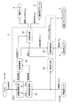
- 9 is a flowchart illustrating a process of transmitting a start trigger.
- FIG. 1 is a configuration diagram of a vehicle to which a vehicle control device according to an embodiment of the present invention is applied.
- the driver instructs forward, backward, and stop of the own vehicle with the shift lever 8, and instructs the driving force of the drive motor 1 with the accelerator pedal 6.
- the drive motor 1 may be an engine.
- the drive motor 1 can generate a driving force and a braking force irrespective of the driver's accelerator pedal operation and shift operation.
- the depression force of the brake pedal 7 is boosted by the brake booster 15, and a hydraulic pressure corresponding to the force is generated in the master cylinder 16.
- the generated hydraulic pressure is supplied to the wheel cylinders 21 to 24 via the electric hydraulic brake 2.
- the electric hydraulic brake 2 incorporates a pump driven by a motor, an electromagnetic valve, and the like, and can independently control the braking force of the four wheels (the hydraulic pressure of the wheel cylinders 21 to 24) independently of the driver's brake pedal operation.
- the electric power steering 3 generates an assist torque according to the steering torque input by the driver via the steering wheel 9, and the left and right front wheels (steered wheels) 41, 42 is steered, and the vehicle turns while the vehicle is running. Further, the electric power steering 3 generates a steering torque irrespective of a driver's steering operation, and can steer the left and right front wheels 41 and 42.
- four cameras 11 to 14 are mounted on the front, rear, left and right of the host vehicle for photographing the surroundings of the vehicle and recognizing objects around the host vehicle.
- the images of the four cameras 11 to 14 are combined and displayed on the touch panel 18 as a bird's-eye view of the vehicle and its surroundings viewed from above. The driver can park while looking at the bird's-eye view without depending on the control of the parking support.
- the vehicle control device recognizes the parking position based on the parking frame on the images of the cameras 11 to 14 and the position of another parked vehicle, and drives the drive motor 1 and the electric hydraulic brake so that the vehicle reaches the recognized parking position. 2. Control the electric power steering 3. Using the touch panel 18 on which the bird's-eye view is displayed, the driver can also instruct the parking position.
- a steering angle sensor 4 and wheel speed sensors 31 to 34 are attached to control the parking route.
- the electro-hydraulic brake 2 uses the vehicle motion detection sensor 17 for detecting longitudinal acceleration, lateral acceleration, and yaw rate, the steering angle sensor 4 and the sensor signals from the wheel speed sensors 31 to 34 to prevent the vehicle from skidding and perform anti-lock brake control.
- the signals from the steering angle sensor 4 and the wheel speed sensors 31 to 34 are shared with the control for parking assistance.
- All of the above-described electric devices are controlled by an electronic control unit (ECU) 5, and all sensor signals are also input to the electronic control unit 5.
- Each sensor signal also includes an accelerator pedal operation amount, a brake pedal operation amount, a shift position, and a steering torque, which are operation amounts of the driver.
- the function of the electronic control unit 5 may be divided, an electronic control unit may be attached to each electric device, and necessary information may be communicated between the electronic control units.
- the drive motor 1, the electric hydraulic brake 2, the wheel cylinders 21 to 24, the wheels 41 to 44, and the electronic control unit 5 constitute an automobile speed control device that automatically controls the vehicle speed.
- the electric power steering 3 and the electronic control unit 5 constitute an automatic steering control device for automatically steering the left and right front wheels 41 and 42.
- FIG. 2 is a configuration diagram of the vehicle control device of the present embodiment.
- the vehicle operation is automatically controlled by the drive motor 1, the electric hydraulic brake 2, and the electric power steering 3, but the driver's operation amount is monitored, and the driver can be overridden.
- the driver operates the brake pedal 7 during automatic driving, the operation of the host vehicle is temporarily stopped.
- the driver's brake operation is prioritized, and contact with the obstacle can be avoided.
- an automatic control stop button may be displayed on the touch panel 18 and the automatic control may be stopped by pressing the automatic control stop button.
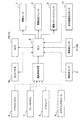
- FIG. 3 is a functional block diagram of the vehicle control device according to the present embodiment.
- the electronic control unit 5 includes a parking route calculation unit 51, a movement distance calculation unit 52, a vehicle speed calculation unit 53, a route control unit 54, a vehicle speed control unit 55, and a steering angle control unit 56.
- the parking route calculation unit 51 recognizes a parking position using images captured by the cameras 11 to 14, calculates a parking route to the parking position, and outputs the calculated parking route to the route control unit 54.
- the travel distance calculation unit 52 calculates the travel distance of the own vehicle based on the wheel speed pulses detected by the wheel speed sensors 31 to 34, and outputs the calculated travel distance to the route control unit 54.
- the route control unit 54 calculates the vehicle speed and the steering angle based on the parking route and the moving distance, and outputs the calculated vehicle speed and the steering angle to the vehicle speed control unit 55 and the steering angle control unit 56.
- the vehicle speed control unit 55 outputs a drive torque command and a hydraulic pressure command to the drive motor 1 and the electric hydraulic brake 2 to control them, and the steering angle control unit 56 receives steering angle information from the steering angle sensor 4. It obtains the steering torque command value and outputs it to the electric power steering 3.
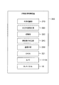
- FIG. 4 is a diagram illustrating internal functions of the vehicle control device.
- the automatic parking control device 300 is one of the internal functions of the vehicle control device, and is configured inside the electronic control unit 5.
- the automatic parking control device 300 includes an external world recognition unit 310, a self-position estimation unit 320, a storage unit 330, and a remote operation determination unit 340.
- a communication unit 350 is provided as a transmission unit that transmits the result of the remote operation determination unit 340 to the outside such as the portable terminal 200 (see FIG. 6).
- the external world recognition unit 310 is connected to the cameras 11 to 14 provided in the own vehicle, and can acquire surrounding information including an object (peripheral obstacle) around the own vehicle and a road surface pattern.
- the external world recognition unit 310 can also acquire peripheral information using a radar or a sonar other than the camera.
- the self-position estimating unit 320 estimates the own-vehicle position based on information from the external world recognizing unit 310.
- the storage unit 330 stores a traveling route to the last parking position and obstacles around the traveling route.
- the remote operation determining unit 340 performs a process of determining that the own vehicle is capable of remote automatic parking based on the self-position estimating unit 320 and the information stored in the storage unit 330.
- the remote automatic parking means that the user operates the mobile terminal 200, which is a mobile communication device, outside the vehicle to move the own vehicle to the final parking position.
- the remote operation determining unit 340 compares the information from the self-position estimating unit 320 and the information from the storage unit 330 and determines that the remote automatic parking is possible after determining that the own vehicle is on a route stored in advance. I do.
- the self-position estimating unit 320 collates the information recorded in the storage unit 330 with the peripheral information acquired from the outside world recognizing unit 310 to estimate the position of the own vehicle.
- the self-position estimating unit 320 includes a GNSS (Global Navigation Satellite System) 321 and can also detect the position information acquired by the GNSS 321 as the current position of the own vehicle. Further, the own position of the own vehicle may be calculated by combining the GNSS 321 and the comparison result.
- the touch panel 18 is provided in the vehicle interior, displays a route to a user, and displays operation buttons of the automatic driving start device.
- FIG. 5 is a diagram showing an example of an automatic parking route.
- the storage unit 330 stores at least one of a self-position on the traveling route 405 from the recording start point 403 to the final parking position 401 and surrounding information including an object (peripheral obstacle) existing around the traveling route 405 and a road surface pattern. Is recorded in advance.
- the recording start point 403 is a position where the recording of the peripheral information has started. This record is recorded in advance by a user's driving operation or the like.
- the recording start point 403 may be the automatic operation startable start point 406.
- the automatic parking control device 300 performs control for automatically driving the own vehicle along the traveling route 405 by automatic driving at least from the start point 406 at which automatic driving can be started to the final parking position 401.
- Automatic driving is performed based on information obtained by various external recognition means and the like. In the present application, the configuration and method are not limited. Automatic driving may be started by a user operation, or may be started automatically. For example, the automatic driving may be started when the remaining travel route length (remaining distance) up to the final parking position 401 becomes equal to or less than a predetermined value.
- the communication means 350 transmits the result of the determination to the mobile terminal 200 when the remote operation determination unit 340 determines that remote automatic parking is possible or impossible.
- FIG. 6 is a diagram showing a configuration of the mobile terminal 200.
- the portable terminal 200 has a notifying unit that notifies by at least one of sound vibration and display.
- a general computer including communication means such as a smartphone and a mobile phone can be used.
- the mobile terminal 200 includes a display 201, an input unit 202, a communication unit 203, a main storage device 204, an auxiliary storage device 205, and a CPU 206.
- the mobile terminal 200 has a function of communicating with the own vehicle using the communication means 203.
- the application executed on the mobile terminal 200 can transmit and receive signals to and from the own vehicle using the communication unit 203.
- the mobile terminal 200 and the host vehicle may communicate directly, or a relay device may be provided on a communication path between the mobile terminal 200 and the host vehicle. Further, communication may be performed via a communication network such as the Internet.
- the mobile terminal 200 has installed therein an application for the user to control automatic parking of the vehicle.
- the automatic parking control application can cause the own vehicle to travel to the final parking position 401 by operating the mobile terminal 200.
- the user can remotely control the start and stop of the traveling of the own vehicle, and can perform the automatic driving from outside the own vehicle.
- FIG. 7 is a diagram illustrating an example of operation buttons displayed on the display of the mobile terminal.
- the mobile terminal 200 is, for example, a smartphone and has a display 201 capable of touch input, as shown in FIG.
- the button 210 is drawn on the touch display 201, and when the user touches the button 210, the own vehicle runs automatically. Further, when the touch on the button 210 is released, the traveling of the host vehicle may be interrupted.
- the automatic parking control application is installed in the mobile terminal 200, and starts automatically when the mobile terminal 200 receives a start trigger from the automatic parking control device 300.
- the remote operation may be automatically started. Then, the user can be notified of the activation of the automatic parking control application by an arbitrary combination of speaker output, vibration output, and screen output (notification unit).
- Self-propelled parking control device 300 records in storage unit 330 when a predetermined user input is performed (S201) or when the position of the own vehicle acquired by GNSS (321) is within a predetermined area (S202). Then, the surrounding information (past external recognition information) corresponding to the position of the own vehicle is called (S203).
- the predetermined area is an area corresponding to a position at which parking is finally performed by automatic parking or a recording start point 403.
- the area is a predetermined radius from the last parking position 401.
- the present invention is not limited to this, and may be an arbitrary area corresponding to the recorded peripheral information.
- a matching process (matching process) between the peripheral information called in S203 and the peripheral information acquired from the external world recognition unit 310 is started.
- the collation is a process of determining whether the peripheral information called in S203 matches the peripheral information acquired from the external world recognition unit 310.
- the peripheral information obtained from the camera it is determined whether the image currently obtained from the camera matches the image stored in the storage unit 330 as the peripheral information.
- Information such as peripheral obstacles (for example, 407 in FIG. 5) obtained from the external recognition unit 310 is converted into point cloud data and recorded in the storage unit 330 as peripheral information.
- the determination may be made based on whether the result of converting the peripheral information acquired from to the point cloud data matches the point cloud data recorded in the storage unit 330.
- the matching condition does not need to be the case where the two match completely, but the degree of matching may be calculated, and when the matching degree is equal to or higher than the set threshold value, it may be determined that the two match. .
- the own position of the own vehicle is estimated. At this time, the calculation of the positional relationship with the obstacle, the last parking position, and the like recorded as the peripheral information is started from the peripheral information recorded in the storage unit 330 and the peripheral information acquired from the external world recognition unit 310.
- the automatic driving start device is, for example, a physical operation button provided in the vehicle interior or an operation button displayed on the touch panel 18, and is operated by the user.
- the automatic driving start device is operated by the user, automatic driving of the own vehicle is started, and the own vehicle is moved along the traveling route.
- the remaining distance (remaining distance) to the final parking position 401 is calculated in S207.
- the remaining distance is considered as a traveling distance in a traveling route from the self-position to the final parking position 401.
- a start trigger is transmitted in S209.
- the start trigger is a trigger for automatically starting the automatic parking control application of the mobile terminal 202.
- the activation trigger is transmitted when it is determined that remote automatic parking is possible on condition that the remote operation determination unit 340 determines that the own vehicle is on the stored route. That is, when the host vehicle moves toward the final parking position 401 by automatic driving and approaches the final parking position 401 by a distance that is set in advance, the activation trigger is transmitted.
- the automatic parking control application starts up, and the mobile terminal 200 enters a state where automatic parking can be performed by remote operation.
- Conditions for transmitting the activation trigger may be further added. For example, in S201 and S202, if subsequent processing has been performed irrespective of user input, a user input may be accepted, and an activation trigger may be transmitted when a predetermined user input is made.
- an end trigger is transmitted (S211).
- the termination trigger is a trigger for automatically terminating the automatic parking control application of the mobile terminal 200.
- an area based on the traveling route 405 is set, and an end trigger is transmitted when the own vehicle exits the area.
- One example of a method for setting the area is an area having a certain width around the line when the travel route 405 is a line.
- the above-mentioned control application may be activated immediately after receiving the activation trigger.
- the getting off position 402 may be set, and the control application may be activated when the vehicle stops at the getting off position.
- the control application such as the restart of the automatic parking is controlled by the user using the control application automatically started.
- the getting-off position 402 may be set when a driving operation is recorded in the storage unit 330 by the user. For example, at the time of recording, the user stops the vehicle at a position that the user wants to set as the getting-off position 402, and when user input such as operation of the touch panel 18 is performed, or when the user opens and closes the door of the vehicle, the position is changed.
- the storage unit 330 is recorded as the getting-off position 402.
- the start timing of the control application may be set based on the arrival timing at the getting off position 402.
- the start timing is set t seconds before the arrival timing.
- the control application can be started before the arrival timing, so that the user does not have to wait for the start of the control application after getting off the vehicle.
- the automatic parking control device 300 calculates the arrival timing based on the speed of the own vehicle and the distance to the getting off position 402, and transmits a control application activation trigger when the current time is t seconds before the arrival timing. .
- the activation timing is transmitted to the portable terminal 200, and the portable terminal 200 activates the control application at a timing corresponding to the received activation timing.
- a start trigger transmission position 404 may be set, and the control application may be started when the vehicle reaches the start trigger transmission position 404.
- the automatic driving start possible start point 406, the getting-off position 402, and the start trigger transmission position 404 are set as the remaining distance to the final parking position 401. Alternatively, they may be set as coordinates and areas.
- an end trigger may be transmitted. Further, when the automatic parking control device 300 detects a failure of the vehicle, the automatic parking may be stopped, and at that time, the end trigger may be transmitted. When the communication between the automatic parking control device 300 and the mobile terminal 200 is interrupted, the automatic parking control device 300 may stop the automatic parking.
- the remote operation determination unit 340 may be provided in a mobile terminal instead of the vehicle control device, or a communication network such as the Internet is used.
- the server may be provided with a remote operation determination unit 340.
- an automatic driving system including a vehicle control device that performs automatic parking control for parking the own vehicle at a final parking position, and a mobile communication device that can transmit and receive the vehicle control device.
- a configuration in which an operation determination unit is provided can be employed.
- the automatic driving system has a vehicle control device and a mobile communication device.
- the vehicle control device includes: a storage unit that stores information on the traveling route to the final parking position, information on an obstacle existing around the traveling route, and information stored in the storage unit and information on the outside world of the own vehicle. And a self-position estimating unit for estimating the own-vehicle position based on information acquired by an external-world recognizing unit for recognizing the vehicle position.
- the mobile communication device includes a remote operation determining unit that determines whether or not remote automatic parking of the own vehicle is possible based on the own vehicle position estimated by the own position estimating unit.
- a notification unit that notifies the user that remote automatic parking is possible by at least one of sound and display and a remote control for performing remote automatic parking of the vehicle.
- a processing unit that executes a process of activating the operation application.
- an automatic driving system having a vehicle control device that performs automatic parking control for parking the vehicle at the final parking position, a server that can transmit and receive the vehicle control device, and a mobile communication device that can transmit and receive the server, A configuration in which the remote operation determination unit 340 is provided can be employed.
- the automatic driving system has a vehicle control device, a server, and a mobile communication device.
- the vehicle control device includes: a storage unit that stores information on the traveling route to the final parking position, information on an obstacle existing around the traveling route, and information stored in the storage unit and information on the outside world of the own vehicle. And a self-position estimating unit for estimating the own-vehicle position based on information acquired by an external-world recognizing unit for recognizing the vehicle position.
- the server includes a remote operation determination unit that determines whether or not remote automatic parking of the own vehicle is possible based on the own vehicle position estimated by the own position estimation unit. Then, when the mobile communication device receives the determination result that the remote automatic parking is possible from the server, the mobile communication device notifies the user that the remote automatic parking is possible by at least one of sound and display. And a processing unit that executes a process of activating a remote control application for performing remote automatic parking of the vehicle.
Landscapes
- Engineering & Computer Science (AREA)
- Transportation (AREA)
- Mechanical Engineering (AREA)
- Automation & Control Theory (AREA)
- Physics & Mathematics (AREA)
- General Physics & Mathematics (AREA)
- Remote Sensing (AREA)
- Radar, Positioning & Navigation (AREA)
- Human Computer Interaction (AREA)
- Chemical & Material Sciences (AREA)
- Combustion & Propulsion (AREA)
- Control Of Driving Devices And Active Controlling Of Vehicle (AREA)
- Traffic Control Systems (AREA)
- Computing Systems (AREA)
- Mathematical Physics (AREA)
- Theoretical Computer Science (AREA)
- Aviation & Aerospace Engineering (AREA)
Abstract
より安全、確実で違和感の無い制御アプリケーションの起動方法を提供する。 記録された周辺情報と現在取得した周辺環境を照合することによって、遠隔自動駐車が可能であるかを判断し、移動体通信機器で実行される遠隔操作用アプリケーションを起動させる。
Description
本発明は、自動運転により最終駐車位置に自車両を駐車させるための車両制御を行う車両制御装置及びそれを用いた自動運転システムに関するものである。
自動運転をスマートフォンアプリケーションによって制御する車両が登場している。車両とスマートフォンを無線通信で接続し、専用のスマートフォンアプリケーションを用いることで、ユーザーは車両外から、車両を移動させることが可能となる。一方で、車両を制御するためのアプリケーションの起動手順は、ユーザーにとって煩雑なものとなる。
特許文献1には、スマートフォンが車両に近づいたとき、制御アプリケーションを自動的に起動させる技術が公開されている。
特許文献1ではGPSに基づく位置情報に応じたトリガによって、スマートフォンの制御アプリケーションを起動させている。しかし、例えば車両の走行中に、自動車と連動して行う場合では、制御アプリケーションの起動や終了の挙動は不安定であってはならず、GPSのような誤差が懸念される位置情報を用いる場合では、不確実な起動や意図せぬ起動なども懸念される。
本発明は、上記の点に鑑みてなされたものであり、その目的とするところは、より安全、確実で違和感の無い制御アプリケーションの起動を行うことができる車両制御装置及びそれを用いた自動運転システムを提供することである。
上記課題を解決する本発明の車両制御装置は、最終駐車位置までの走行経路と、その周辺障害物と、を記憶する記憶部と、外界認識部からの情報により自車位置を推定する自己位置推定部と、前記自己位置推定部と、前記記憶部に記憶された情報に基づき、自車両が遠隔自動駐車可能であることを判定する遠隔操作判定部と、を備え、前記遠隔操作判定部は、前記自己位置推定部と前記記憶部からの情報を比較して、自車両が記憶されている経路上にいると判定したことを条件に、遠隔自動駐車が可能であると判定することを特徴とする。
本発明によれば、記憶部に記録された周辺情報と現在取得した周辺環境を照合することによって、自車両を最終駐車位置まで移動させる自動運転が可能であるかを判断し、移動体通信機器で実行される自動運転制御アプリケーションを自動的に起動させることによって、自動運転を実行するために必要なユーザー操作手順を減らすことが可能となり、より扱いやすい自動運転システムを提供することが出来る。
本発明に関連する更なる特徴は、本明細書の記述、添付図面から明らかになるものである。また、上記した以外の、課題、構成及び効果は、以下の実施形態の説明により明らかにされる。
一例として、駐車動作を自動化する制御装置を搭載した車両を用いて説明する。
[車両の構成]
図1は、本発明の実施形態における車両制御装置を適用した車両の構成図である。
運転者はシフトレバー8によって自車両の前進、後退、停止を指示し、アクセルペダル6によって駆動モータ1の駆動力を指示する。駆動モータ1はエンジンとしてもよい。駆動モータ1は運転者のアクセルペダル操作、シフト操作とは無関係に駆動力、制動力を発生可能である。
図1は、本発明の実施形態における車両制御装置を適用した車両の構成図である。
運転者はシフトレバー8によって自車両の前進、後退、停止を指示し、アクセルペダル6によって駆動モータ1の駆動力を指示する。駆動モータ1はエンジンとしてもよい。駆動モータ1は運転者のアクセルペダル操作、シフト操作とは無関係に駆動力、制動力を発生可能である。
ブレーキペダル7の踏力はブレーキブースタ15によって倍力され、その力に応じた油圧がマスタシリンダ16に発生する。発生した油圧は、電動油圧ブレーキ2を介してホイルシリンダ21~24に供給される。このように、運転者はブレーキペダル7によって制動力を制御する。電動油圧ブレーキ2はモータで駆動するポンプや電磁弁等を内蔵し、運転者のブレーキペダル操作とは無関係に4輪の制動力(ホイルシリンダ21~24の油圧)を独立に制御可能である。
電動パワーステアリング3は、運転者がステアリングホイール9を介して入力した操舵トルクに応じたアシストトルクを発生し、運転者の操舵トルクと電動パワーステアリング3のアシストトルクによって左右前輪(操舵輪)41,42が操舵され、車両走行中には自車両が旋回する。また、電動パワーステアリング3は運転者のステア操作とは無関係にステアトルクを発生し、左右前輪41,42を操舵可能である。
また、車両周辺を撮影し、自車両周辺の対象物を認識する4つのカメラ11~14が自車両の前後左右に取り付けられている。4つのカメラ11~14の映像は合成され、自車両及びその周辺を上方から見下ろした俯瞰図としてタッチパネル18に表示される。運転者は駐車支援の制御によらず、この俯瞰図を見ながら駐車を行うこともできる。
車両制御装置は、カメラ11~14の映像上の駐車枠や他の駐車車両の位置に基づいて駐車位置を認識し、認識した駐車位置に自車両が到達するように駆動モータ1、電動油圧ブレーキ2、電動パワーステアリング3を制御する。俯瞰図が表示されたタッチパネル18を用いて、運転者が駐車位置を指示することも可能である。
また、駐車経路を制御するため、操舵角センサ4と車輪速センサ31~34が取り付けられている。電動油圧ブレーキ2は、前後加速度、横加速度、ヨーレートを検出する車両運動検出センサ17と操舵角センサ4と車輪速センサ31~34からのセンサ信号によって、自車両の横滑り防止やアンチロックブレーキ制御を行うが、操舵角センサ4と車輪速センサ31~34の信号は駐車支援の制御と共用される。
以上挙げた電動装置は全て電子制御ユニット(ECU)5によって制御され、各センサ信号も全て電子制御ユニット5に入力される。各センサ信号には運転者の操作量である、アクセルペダル操作量、ブレーキペダル操作量、シフト位置、操舵トルクも含まれる。また、電子制御ユニット5の機能を分割し、各電動装置に電子制御ユニットを取り付け、各電子制御ユニット間で必要な情報を通信する構成とすることもできる。
駆動モータ1、電動油圧ブレーキ2、各ホイルシリンダ21~24、各車輪41~44および電子制御ユニット5により、車速を自動的にコントロールする自動車速制御装置が構成される。また、電動パワーステアリング3、および電子制御ユニット5により、左右前輪41,42を自動的に操舵する自動操舵制御装置が構成される。
[車両制御装置の構成]
図2は、本実施形態の車両制御装置の構成図である。
自動運転中は、駆動モータ1、電動油圧ブレーキ2、電動パワーステアリング3によって自動的に車両動作が制御されるが、運転者操作量は監視されており、運転者のオーバーライドが可能である。例えば、自動運転中に運転者がブレーキペダル7を操作した場合は、自車両の動作を一時停止させる。これにより、走行経路上に障害物が進入した場合には、運転者のブレーキ操作を優先し、障害物との接触を回避できる。
図2は、本実施形態の車両制御装置の構成図である。
自動運転中は、駆動モータ1、電動油圧ブレーキ2、電動パワーステアリング3によって自動的に車両動作が制御されるが、運転者操作量は監視されており、運転者のオーバーライドが可能である。例えば、自動運転中に運転者がブレーキペダル7を操作した場合は、自車両の動作を一時停止させる。これにより、走行経路上に障害物が進入した場合には、運転者のブレーキ操作を優先し、障害物との接触を回避できる。
その後、運転者がブレーキを解除すると、自動運転による駐車動作が再開される。これにより、障害物が駐車経路から離れた場合は、自動的に駐車支援を再開できる。また、運転者がシフト位置を変更するか、運転者の操舵トルクが所定値以上になった場合は自動運転による駐車動作を中止する。これにより、運転者のシフト操作またはステア操作を優先して自車両を走行させることができる。なお、タッチパネル18に自動制御中止ボタンを表示し、この自動制御中止ボタンを押すことで自動制御を中止することもできる。
図3は、本実施形態における車両制御装置の機能ブロック図である。
電子制御ユニット5は、駐車経路算出部51と、移動距離計算部52と、車速計算部53と、経路制御部54と、車速制御部55と、操舵角制御部56を備えている。駐車経路算出部51は、カメラ11~14で撮像した画像を用いて駐車位置を認識し、駐車位置までの駐車経路を算出し、経路制御部54に出力する。移動距離計算部52は、車輪速センサ31~34により検出される車輪速パルスにより自車両の移動距離を計算し、経路制御部54に出力する。経路制御部54は、駐車経路と移動距離に基づいて車速と操舵角を算出し、車速制御部55と操舵角制御部56に出力する。車速制御部55は、駆動モータ1と電動油圧ブレーキ2に対して駆動トルク指令と液圧指令を出力してこれらを制御し、操舵角制御部56は、操舵角センサ4から操舵角の情報を取得し、ステアトルク指令値を算出して電動パワーステアリング3に出力する。
電子制御ユニット5は、駐車経路算出部51と、移動距離計算部52と、車速計算部53と、経路制御部54と、車速制御部55と、操舵角制御部56を備えている。駐車経路算出部51は、カメラ11~14で撮像した画像を用いて駐車位置を認識し、駐車位置までの駐車経路を算出し、経路制御部54に出力する。移動距離計算部52は、車輪速センサ31~34により検出される車輪速パルスにより自車両の移動距離を計算し、経路制御部54に出力する。経路制御部54は、駐車経路と移動距離に基づいて車速と操舵角を算出し、車速制御部55と操舵角制御部56に出力する。車速制御部55は、駆動モータ1と電動油圧ブレーキ2に対して駆動トルク指令と液圧指令を出力してこれらを制御し、操舵角制御部56は、操舵角センサ4から操舵角の情報を取得し、ステアトルク指令値を算出して電動パワーステアリング3に出力する。
図4は、車両制御装置の内部機能を説明する図である。
自動駐車制御装置300は、車両制御装置の内部機能の一つであり、電子制御ユニット5の内部に構成される。自動駐車制御装置300は、外界認識部310と、自己位置推定部320と、記憶部330と、遠隔操作判定部340を備える。また、遠隔操作判定部340の結果を携帯端末200(図6参照)などの外部に送信する送信部として通信手段350を備える。
自動駐車制御装置300は、車両制御装置の内部機能の一つであり、電子制御ユニット5の内部に構成される。自動駐車制御装置300は、外界認識部310と、自己位置推定部320と、記憶部330と、遠隔操作判定部340を備える。また、遠隔操作判定部340の結果を携帯端末200(図6参照)などの外部に送信する送信部として通信手段350を備える。
外界認識部310は、自車両が備えるカメラ11~14と接続されており、自車両の周辺に存在する物体(周辺障害物)や路面の模様を含む周辺情報を取得することが出来る。外界認識部310は、カメラの他にも、レーダーやソナーを用いて周辺情報を取得することもできる。
自己位置推定部320は、外界認識部310からの情報により自車位置を推定する。記憶部330は、最終駐車位置までの走行経路と、その周辺障害物とを記憶する。遠隔操作判定部340は、自己位置推定部320と、記憶部330に記憶された情報に基づき、自車両が遠隔自動駐車可能であることを判定する処理を行う。ここで、遠隔自動駐車とは、ユーザーが車外において移動体通信機器である携帯端末200を操作して、自車両を最終駐車位置に移動させることである。遠隔操作判定部340は、自己位置推定部320と記憶部330からの情報を比較して、自車両が予め記憶されている経路上にいると判定した後に、遠隔自動駐車が可能であると判定する。
自己位置推定部320は、記憶部330に記録されている情報と、外界認識部310から取得される周辺情報とを照合して、自車位置を推定する。自己位置推定部320は、GNSS(Global Navigation Satellite System)321を含み、GNSS321によって取得した位置情報を自車両の現在地として検出することもできる。また、GNSS321と前記比較結果とを組み合わせて、自車両の自己位置を算出してもよい。タッチパネル18は、車室内に設けられておりユーザーに経路を表示し、また、自動運転開始装置の操作ボタンを表示する。
図5は、自動駐車の経路の一例を示す図である。記憶部330は、記録始点403から最終駐車位置401までの走行経路405における自己位置と、走行経路405の周辺に存在する物体(周辺障害物)や路面の模様を含む周辺情報との少なくともいずれかを予め記録する。記録始点403とは、周辺情報の記録が開始された位置とする。この記録は、ユーザーの運転操作などによって事前に記録されることとする。
記録始点403から最終駐車位置401の間に自動運転開始可能始点406を設定する。記録始点403を自動運転開始可能始点406としてもよい。
自動駐車制御装置300は、少なくとも自動運転開始可能始点406から最終駐車位置401までの間、自動運転によって自車両を走行経路405に沿って自動的に走行させる制御を行う。自動運転は、各種外界認識手段などによって得られる情報を基に行われる。本願においては、その構成や手法は問わない。自動運転は、ユーザー操作によって開始してもよいし、自動的に開始してもよい。例えば、最終駐車位置401までの残りの走行経路長(残距離)が所定の値以下となった場合に自動運転を開始してもよい。
通信手段350は、遠隔操作判定部340により遠隔自動駐車が可能であると判定された場合、または、不可能であると判定された場合に、その判定結果を携帯端末200に送信する。
図6は、携帯端末200の構成を示す図である。
携帯端末200は、音振または表示の少なくとも一つにより通知する通知部を有している。携帯端末200は、スマートフォンや携帯電話など、通信手段を備えた一般的なコンピュータを用いることができる。携帯端末200は、ディスプレイ201、入力手段202、通信手段203、主記憶装置204、補助記憶装置205、CPU206を備える。
携帯端末200は、音振または表示の少なくとも一つにより通知する通知部を有している。携帯端末200は、スマートフォンや携帯電話など、通信手段を備えた一般的なコンピュータを用いることができる。携帯端末200は、ディスプレイ201、入力手段202、通信手段203、主記憶装置204、補助記憶装置205、CPU206を備える。
携帯端末200は、通信手段203を用いて自車両と通信可能な機能を有する。携帯端末200で実行されるアプリケーションは、通信手段203を用いて、自車両と信号の送受信が可能である。携帯端末200と自車両は、直接通信してもよいし、携帯端末200と自車両との通信経路に中継機器を設けてもよい。また、インターネット等の通信ネットワークを介して通信を行ってもよい。
携帯端末200には、自車両の自動駐車をユーザーが制御するためのアプリケーションがインストールされている。自動駐車制御アプリケーションは、携帯端末200の操作によって自車両を最終駐車位置401まで走行させることができる。例えば、ユーザーは、携帯端末200で自動駐車制御アプリケーションを操作することによって、自車両の走行の開始や停止を遠隔操作することができ、自車両の外から自動運転を行わせることが可能となる。
図7は、携帯端末のディスプレイに表示される操作ボタンの一例を示す図である。
図7は、携帯端末のディスプレイに表示される操作ボタンの一例を示す図である。
携帯端末200は、図7に示すように、例えばスマートフォンであり、タッチ入力が可能なディスプレイ201を有する。携帯端末200は、タッチディスプレイ201にボタン210が描画され、ユーザーがボタン210をタッチしたとき、自車両が自動的に走行する。また、ボタン210へのタッチを解途したとき、自車両の走行を中断させてもよい。
自動駐車制御アプリケーションは、携帯端末200にインストールされており、携帯端末200が自動駐車制御装置300から起動トリガを受信することによって、自動的に起動する。
また、遠隔操作判定部340の判定結果が遠隔自動駐車可能の場合に、自動的に起動してもよい。そして、スピーカ出力、振動出力、画面出力の任意の組み合わせによって、ユーザーに対して自動駐車制御アプリケーションが起動したことの通知を行うことが出来る(通知部)。
また、遠隔操作判定部340の判定結果が遠隔自動駐車可能の場合に、自動的に起動してもよい。そして、スピーカ出力、振動出力、画面出力の任意の組み合わせによって、ユーザーに対して自動駐車制御アプリケーションが起動したことの通知を行うことが出来る(通知部)。
自動駐車制御装置300の起動トリガ送信について、図8を基に処理の流れを説明する。自走駐車制御装置300は、所定のユーザー入力が行われる(S201)、或いは、GNSS(321)によって取得した自車両の位置が、所定の領域内である(S202)とき、記憶部330に記録された、自車両の位置に対応する周辺情報(過去の外界認識情報)を呼び出す(S203)。ここで、所定の領域とは、自動駐車によって最終的に駐車する位置、或いは記録始点403に応じた領域とする。例えば、最終駐車位置401から所定の半径の領域とする。当然、これに限らず、その他、記録された周辺情報に応じた任意の領域としてもよい。
S204において、S203で呼び出した周辺情報と、外界認識部310から取得される周辺情報との照合処理(マッチング処理)を開始する。ここで、照合とは、S203で呼び出した周辺情報と、外界認識部310から取得される周辺情報が一致しているかを判断する処理である。例えば、カメラから得られる周辺情報を用いる場合では、現在カメラから取得される画像が、周辺情報として記憶部330に保存された画像に一致しているかを判断する。外界認識部310から取得される周辺の障害物(例えば図5の407)などの情報を、点群データに変換して、周辺情報として記憶部330に記録し、照合処理において、外界認識部310から取得される周辺情報を点群データに変換した結果が、記憶部330に記録した点群データと一致しているかで判断してもよい。ここで、一致の条件は、完全に一致している場合とする必要はなく、一致の度合いを算出し、設定された閾値以上の一致度合いであったとき一致していると判断してもよい。
S204において、一致していると判断すると、S205において、自車両の自己位置推定を行う。このとき、記憶部330に記録された周辺情報と、外界認識部310から取得される周辺情報から、周辺情報として記録された障害物や最終駐車位置などとの位置関係の算出を開始する。
S205で自己位置の推定が完了すると、S206において、自動運転開始装置が操作されたかが判断される。自動運転開始装置は、例えば車室内に設けられている物理的な操作ボタン、或いは、タッチパネル18に表示された操作ボタンであり、ユーザーによって操作される。この自動運転開始装置がユーザーによって操作されると、自車両の自動運転が開始され、自車両は走行経路に沿って移動される。
S206の操作によって自車両の自動運転が開始されると、S207において、最終駐車位置401までの残りの距離(残距離)を算出する。ここで、残距離とは、自己位置から、最終駐車位置401までの走行経路における走行距離として考える。
そして、S208において、自己位置と最終駐車位置までの残距離が通知可能距離以下であるかを判定する。残距離が通知可能距離以下のとき、S209において、起動トリガを送信する。起動トリガとは、携帯端末202の自動駐車制御アプリケーションを自動的に起動させるためのトリガである。起動トリガは、遠隔操作判定部340により自車両が記憶されている経路上にいると判定したことを条件に遠隔自動駐車が可能であると判定された場合に送信される。つまり、自車両が自動運転により最終駐車位置401に向かって移動し、最終駐車位置401に対して予め設定された距離よりも接近した場合に、起動トリガが送信される。そして、携帯端末200では、起動トリガの受信により、自動駐車制御アプリケーションが立ち上がり、携帯端末200による遠隔操作によって自動駐車が可能な状態となる。
起動トリガの送信の為の条件をさらに加えてもよい。例えば、S201,S202において、ユーザー入力によらず、以降の処理がされていた場合、ユーザー入力を受け付け、所定ユーザー入力がされたとき起動トリガを送信するようにしてもよい。
S210において、自車両が通知可能区間内に位置しているかを判定してもよい。自車両の自車位置が通知可能区間外となったとき、終了トリガを送信する(S211)。終了トリガとは、携帯端末200の自動駐車制御アプリケーションを自動的に終了させるためのトリガである。通知可能区間の一例は、走行経路405を基準とした領域を設定し、自車両が領域から出たとき、終了トリガを送信する。前記領域の設定方法の一例は、走行経路405を線としたとき、線を中心とした一定の幅を持つ領域とする。
S212において、自車両が最終駐車位置401まで移動したか(終点に達したか)、即ち、駐車が完了したかを判断する。駐車が完了した場合、前記終了トリガを送信してもよい。
携帯端末200の制御アプリケーションを自動的に起動させるための起動トリガの送信を、記録された周辺情報と現在の周辺情報が一致している場合に行うことによって、意図しないタイミングでの起動を防ぐことが可能となる。例えば、GPSなどGNSSの位置情報のみを起動トリガ送信の条件とした場合、GNSSの誤差により意図しない場所で、制御アプリケーションが起動してしまう恐れがある。また、地下駐車場などのようにGNSSを利用できない場所では、制御アプリケーションを自動的に起動させることが出来ない。S204の照合処理を行うことによって、これらの問題を解決可能である。
S202における、GPSによる自己位置を条件にS204の照合処理を開始させることによって、自動駐車を行わない通常時において、照合処理にかかる計算負荷を抑えることが出来る。
S201における、ユーザー入力がされた場合に、照合処理を開始させることによって、ユーザーの意図しない制御アプリケーションの自動起動をしないようにすることが可能となる。
S210において、車両位置が通知可能区間外に出たとき、制御アプリケーションを自動的に終了させることによって、例えば、ユーザーの運転によって、自車両が自動駐車することが出来る領域に入ったものの、ユーザーに駐車の意思がなく、或いはなくなり、駐車位置から離れた場合に自動的に起動した制御アプリケーションを自動的に終了させることが可能となる。
上記した制御アプリケーションの起動は、起動トリガ受信後直ちに行ってもよい。或いは、降車位置402を設定し、自車両が降車位置に停車したときに、制御アプリケーションを起動させるようにしてもよい。ここで、自車両は走行経路405での自動駐車において、降車位置402まで走行すると、乗員を降車させるために一時的に停車するものとする。その後の自動駐車の再開などの制御は、自動的に起動した制御アプリケーションを用いてユーザーが制御する。
降車位置402は、ユーザーによる記憶部330への運転操作の記録時に設定されるものとしてもよい。例えば、記録時に、ユーザーが降車位置402に設定したい位置で自車両を停車させ、タッチパネル18の操作などのユーザー入力がなされたとき、或いはユーザーが自車両のドアを開閉することによって、その位置を降車位置402として記憶部330に記録させる。
降車位置402への到達タイミングを基準とした制御アプリケーションの起動タイミングを設定してもよい。起動タイミングは、到達タイミングのt秒前、というように設定する。これによって、制御アプリケーションを到達タイミングより前に起動させることが可能となるので、ユーザーは降車後、制御アプリケーションの起動を待たずに済む。
自動駐車制御装置300は、自車両の速度や降車位置402までの距離を基に、到達タイミングを算出し、現在時刻が到達タイミングのt秒前となったときに、制御アプリケーション起動トリガを送信する。或いは、起動タイミングを携帯端末200に送信し、携帯端末200は受信した起動タイミングに応じたタイミングで制御アプリケーションを起動する。前記タイミングで判断する代わりに起動トリガ送信位置404を設定し、自車両が起動トリガ送信位置404に到達したときに、制御アプリケーションを起動するようにしてもよい。自動運転開始可能始点406、降車位置402、起動トリガ送信位置404は、最終駐車位置401までの残距離として設定する。或いは、座標、領域として設定してもよい。
制御アプリケーションの起動後に、タッチパネル18や入力手段202へのユーザー操作によって、自動駐車が中止されたとき、終了トリガを送信してもよい。また、自動駐車制御装置300が、自車両の故障を検出したとき、自動駐車を中止してもよく、その際、前記終了トリガを送信してもよい。自動駐車制御装置300と携帯端末200との通信が途切れたとき、自動駐車制御装置300は自動駐車を中止してもよい。
なお、上記した実施形態では、遠隔操作判定部340を車両制御装置に設けた場合について説明したが、車両制御装置の代わりに携帯端末に設けてもよく、また、インターネットなどの通信ネットワークを使用する場合には、サーバーに遠隔操作判定部340を設けてもよい。
例えば、自車両を最終駐車位置に駐車させる自動駐車制御を行う車両制御装置と、車両制御装置と送受信可能な移動体通信機器とを有する自動運転システムとし、移動体通信機器として、携帯端末に遠隔操作判定部を設ける構成とすることができる。自動運転システムは、車両制御装置と移動体通信機器とを有する。車両制御装置は、最終駐車位置までの走行経路の情報と、走行経路の周辺に存在する障害物の情報と、を記憶する記憶部と、記憶部に記憶された情報と自車両の外界の情報を認識する外界認識部により取得した情報とに基づいて自車位置を推定する自己位置推定部と、を備える。そして、移動体通信機器は、自己位置推定部により推定した自車位置に基づき、自車両の遠隔自動駐車が可能であるか否かを判定する遠隔操作判定部と、遠隔操作判定部により遠隔自動駐車が可能であると判定された場合に、使用者に遠隔自動駐車が可能であることを音振または表示の少なくとも一つにより通知する通知部と、自車両の遠隔自動駐車を行うための遠隔操作用アプリケーションを起動する処理を実行する処理部と、を備える。
また、自車両を最終駐車位置に駐車させる自動駐車制御を行う車両制御装置と、車両制御装置と送受信可能なサーバーと、サーバーと送受信可能な移動体通信機器とを有する自動運転システムとし、サーバーに遠隔操作判定部340を設ける構成とすることができる。
自動運転システムは、車両制御装置と、サーバーと、移動体通信機器を有する。車両制御装置は、最終駐車位置までの走行経路の情報と、走行経路の周辺に存在する障害物の情報と、を記憶する記憶部と、記憶部に記憶された情報と自車両の外界の情報を認識する外界認識部により取得した情報とに基づいて自車位置を推定する自己位置推定部と、を備える。そして、サーバーは、自己位置推定部により推定した自車位置に基づき、自車両の遠隔自動駐車が可能であるか否かを判定する遠隔操作判定部を備える。それから、移動体通信機器は、サーバーから遠隔自動駐車が可能であるという判定結果を受信した場合に、使用者に遠隔自動駐車が可能であることを音振または表示の少なくとも一つにより通知する通知部と、自車両の遠隔自動駐車を行うための遠隔操作用アプリケーションを起動する処理を実行する処理部と、を備える。
自動運転システムは、車両制御装置と、サーバーと、移動体通信機器を有する。車両制御装置は、最終駐車位置までの走行経路の情報と、走行経路の周辺に存在する障害物の情報と、を記憶する記憶部と、記憶部に記憶された情報と自車両の外界の情報を認識する外界認識部により取得した情報とに基づいて自車位置を推定する自己位置推定部と、を備える。そして、サーバーは、自己位置推定部により推定した自車位置に基づき、自車両の遠隔自動駐車が可能であるか否かを判定する遠隔操作判定部を備える。それから、移動体通信機器は、サーバーから遠隔自動駐車が可能であるという判定結果を受信した場合に、使用者に遠隔自動駐車が可能であることを音振または表示の少なくとも一つにより通知する通知部と、自車両の遠隔自動駐車を行うための遠隔操作用アプリケーションを起動する処理を実行する処理部と、を備える。
以上、本発明の実施形態について詳述したが、本発明は、前記の実施形態に限定されるものではなく、特許請求の範囲に記載された本発明の精神を逸脱しない範囲で、種々の設計変更を行うことができるものである。例えば、前記した実施の形態は本発明を分かりやすく説明するために詳細に説明したものであり、必ずしも説明した全ての構成を備えるものに限定されるものではない。また、ある実施形態の構成の一部を他の実施形態の構成に置き換えることが可能であり、また、ある実施形態の構成に他の実施形態の構成を加えることも可能である。さらに、各実施形態の構成の一部について、他の構成の追加・削除・置換をすることが可能である。
1 駆動モータ
2 電動油圧ブレーキ
3 電動パワーステアリング
4 操舵角センサ
5 電子制御ユニット
6 アクセルペダル
7 ブレーキペダル
8 シフトレバー
11~14 カメラ
200 携帯端末
201 タッチディスプレイ
202 入力手段
203 通信手段
210 ボタン
300 自動駐車制御装置
310 外界認識部
320 自己位置推定部
321 GNSS
330 記憶部
350 通信手段
401 最終駐車位置
402 降車位置
403 記録始点
404 起動トリガ送信位置
405 走行経路
406 自動運転開始可能始点
407 障害物
2 電動油圧ブレーキ
3 電動パワーステアリング
4 操舵角センサ
5 電子制御ユニット
6 アクセルペダル
7 ブレーキペダル
8 シフトレバー
11~14 カメラ
200 携帯端末
201 タッチディスプレイ
202 入力手段
203 通信手段
210 ボタン
300 自動駐車制御装置
310 外界認識部
320 自己位置推定部
321 GNSS
330 記憶部
350 通信手段
401 最終駐車位置
402 降車位置
403 記録始点
404 起動トリガ送信位置
405 走行経路
406 自動運転開始可能始点
407 障害物
Claims (14)
- 最終駐車位置までの走行経路と、その周辺障害物と、を記憶する記憶部と、
外界認識部からの情報により自車位置を推定する自己位置推定部と、
前記自己位置推定部と、前記記憶部に記憶された情報に基づき、自車両が遠隔自動駐車可能であることを判定する遠隔操作判定部と、を備え、
前記遠隔操作判定部は、前記自己位置推定部と前記記憶部からの情報を比較して、前記自車両が予め記憶されている走行経路上にいると判定したことを条件に、遠隔自動駐車が可能であると判定する車両制御装置。 - 前記遠隔操作判定部が可能と判定した場合、その結果を外部に送信する通信部と、を有する請求項1に記載の車両制御装置。
- 前記自己位置推定部は、前記記憶部に記憶された情報と前記自車両の外界の情報を認識する外界情報認識部から取得した情報とを照合するマッチング処理により前記自車位置を推定することを特徴とする請求項2に記載の車両制御装置。
- 前記遠隔操作判定部は、前記自車両が前記走行経路上にいる場合に、前記遠隔自動駐車が可能であると判定することを特徴とする請求項3に記載の車両制御装置。
- 前記遠隔操作判定部は、前記自己位置推定部により前記自車位置が推定されたときに、前記遠隔自動駐車が可能であると判定することを特徴とする請求項3に記載の車両制御装置。
- 前記遠隔操作判定部は、前記自車両を自動駐車させる信号が入力されたときに、前記遠隔自動駐車が可能であると判定することを特徴とする請求項3に記載の車両制御装置。
- 前記遠隔操作判定部は、前記自己位置推定部と前記記憶部からの情報を比較して、前記自車両が予め記憶されている走行経路上から外れている場合、前記遠隔自動駐車が不可能であると判定し、
前記通信部は、前記遠隔自動駐車が不可能であることを外部へ送信することを特徴とする請求項3に記載の車両制御装置。 - 請求項2から請求項7のいずれか一項に記載の車両制御装置と、
前記車両制御装置から前記遠隔自動駐車が可能であるという判定結果を受信した場合に、音振または表示の少なくとも一つにより使用者にその状態を通知する通知部と、前記自車両の遠隔自動駐車を行うための遠隔操作用アプリケーションを起動する処理を実行する処理部とを有する移動体通信機器と、
を備えることを特徴とする自動運転システム。 - 前記遠隔操作判定部により前記遠隔自動駐車が不可能であると判定した場合に、前記通信部はその判定結果を前記移動体通信機器に送信し、
前記移動体通信機器は、前記遠隔自動駐車が不可能であるという判定結果を受信した場合に、前記処理部による前記遠隔操作用アプリケーションの処理を終了させることを特徴とする請求項8に記載の自動運転システム。 - 前記移動体通信機器は、スマートフォンであることを特徴とする請求項8または請求項9に記載の自動運転システム。
- 前記通信部は、サーバーに遠隔操作判定部による可能/不可能情報を送信し、
前記移動体通信機器は、前記サーバーを介して結果を受信することを特徴とする請求項8から請求項10のいずれか一項に記載の自動運転システム。 - 前記移動体通信機器と前記通信部との通信が途絶えたとき、前記自車両の自動運転を中止することを特徴とする請求項8から請求項11のいずれか一項に記載の自動運転システム。
- 自車両を最終駐車位置に駐車させる自動駐車制御を行う車両制御装置と、該車両制御装置と送受信可能な移動体通信機器と、を有する自動運転システムであって、
前記車両制御装置は、最終駐車位置までの走行経路の情報と、該走行経路の周辺に存在する障害物の情報と、を記憶する記憶部と、前記記憶部に記憶された情報と前記自車両の外界の情報を認識する外界認識部により取得した情報とに基づいて自車位置を推定する自己位置推定部と、を備え、
前記移動体通信機器は、前記自己位置推定部により推定した自車位置に基づき、前記自車両の遠隔自動駐車が可能であるか否かを判定する遠隔操作判定部と、該遠隔操作判定部により前記遠隔自動駐車が可能であると判定された場合に、使用者に前記遠隔自動駐車が可能であることを音振または表示の少なくとも一つにより通知する通知部と、前記自車両の遠隔自動駐車を行うための遠隔操作用アプリケーションを起動する処理を実行する処理部と、を備えることを特徴とする自動運転システム。 - 自車両を最終駐車位置に駐車させる自動駐車制御を行う車両制御装置と、該車両制御装置と送受信可能なサーバーと、該サーバーと送受信可能な移動体通信機器と、を有する自動運転システムであって、
前記車両制御装置は、最終駐車位置までの走行経路の情報と、該走行経路の周辺に存在する障害物の情報と、を記憶する記憶部と、前記記憶部に記憶された情報と前記自車両の外界の情報を認識する外界認識部により取得した情報とに基づいて自車位置を推定する自己位置推定部と、を備え、
前記サーバーは、前記自己位置推定部により推定した自車位置に基づき、前記自車両の遠隔自動駐車が可能であるか否かを判定する遠隔操作判定部を備え、
前記移動体通信機器は、前記サーバーから前記遠隔自動駐車が可能であるという判定結果を受信した場合に、使用者に前記遠隔自動駐車が可能であることを音振または表示の少なくとも一つにより通知する通知部と、前記自車両の遠隔自動駐車を行うための遠隔操作用アプリケーションを起動する処理を実行する処理部と、を備える
ことを特徴とする自動運転システム。
Priority Applications (4)
| Application Number | Priority Date | Filing Date | Title |
|---|---|---|---|
| DE112019002285.7T DE112019002285T5 (de) | 2018-07-26 | 2019-07-11 | Fahrzeugsteuervorrichtung und system für das automatische fahren unter verwendung derselben |
| CN201980031711.6A CN112424043A (zh) | 2018-07-26 | 2019-07-11 | 车辆控制装置以及使用它的自动驾驶系统 |
| JP2020532284A JPWO2020022075A1 (ja) | 2018-07-26 | 2019-07-11 | 車両制御装置及びそれを用いた自動運転システム |
| US16/973,257 US20210245734A1 (en) | 2018-07-26 | 2019-07-11 | Vehicle control device and automatic driving system using same |
Applications Claiming Priority (2)
| Application Number | Priority Date | Filing Date | Title |
|---|---|---|---|
| JP2018-140764 | 2018-07-26 | ||
| JP2018140764 | 2018-07-26 |
Publications (1)
| Publication Number | Publication Date |
|---|---|
| WO2020022075A1 true WO2020022075A1 (ja) | 2020-01-30 |
Family
ID=69181400
Family Applications (1)
| Application Number | Title | Priority Date | Filing Date |
|---|---|---|---|
| PCT/JP2019/027449 Ceased WO2020022075A1 (ja) | 2018-07-26 | 2019-07-11 | 車両制御装置及びそれを用いた自動運転システム |
Country Status (5)
| Country | Link |
|---|---|
| US (1) | US20210245734A1 (ja) |
| JP (1) | JPWO2020022075A1 (ja) |
| CN (1) | CN112424043A (ja) |
| DE (1) | DE112019002285T5 (ja) |
| WO (1) | WO2020022075A1 (ja) |
Cited By (4)
| Publication number | Priority date | Publication date | Assignee | Title |
|---|---|---|---|---|
| JP2023114501A (ja) * | 2022-02-07 | 2023-08-18 | トヨタ自動車株式会社 | リモート駐車装置 |
| KR20230174283A (ko) * | 2021-08-05 | 2023-12-27 | 미츠비시 가스 가가쿠 가부시키가이샤 | 경화성 조성물, 프리프레그, 금속박 피복 적층판 및 프린트 배선판 |
| JP2024062074A (ja) * | 2022-10-24 | 2024-05-09 | 本田技研工業株式会社 | 制御装置、制御方法、及び制御プログラム |
| WO2025062769A1 (ja) * | 2023-09-21 | 2025-03-27 | 日立Astemo株式会社 | 車両制御装置、制御方法、及び車両制御システム |
Families Citing this family (5)
| Publication number | Priority date | Publication date | Assignee | Title |
|---|---|---|---|---|
| JP6990687B2 (ja) * | 2019-06-24 | 2022-01-12 | 本田技研工業株式会社 | 駐車支援システム |
| KR102916364B1 (ko) * | 2019-10-31 | 2026-01-23 | 현대자동차주식회사 | 차량 및 차량의 제어방법 |
| JP7360484B2 (ja) * | 2022-01-24 | 2023-10-12 | 本田技研工業株式会社 | 制御装置、制御システム、制御方法、及び制御プログラム |
| KR20240032433A (ko) * | 2022-09-02 | 2024-03-12 | 현대자동차주식회사 | 차량 및 그 제어 방법 |
| DE102022133892A1 (de) * | 2022-12-19 | 2024-06-20 | Valeo Schalter Und Sensoren Gmbh | Verfahren zum Betreiben eines Fahrzeugs, bei welchem ein Teleoperator die Fahrzeugführung an ein Fahrerassistenzsystem abgibt, und Fernsteuerstation |
Citations (5)
| Publication number | Priority date | Publication date | Assignee | Title |
|---|---|---|---|---|
| JP2006321291A (ja) * | 2005-05-17 | 2006-11-30 | Fuji Heavy Ind Ltd | 車両の走行軌跡生成方法、及びそれを利用した駐車支援装置 |
| JP2013530867A (ja) * | 2010-06-09 | 2013-08-01 | ヴァレオ・シャルター・ウント・ゼンゾーレン・ゲーエムベーハー | 駐車スペースへの駐車時における自動車運転者支援方法、運転者支援装置、および自動車 |
| JP2016099953A (ja) * | 2014-11-26 | 2016-05-30 | 株式会社デンソー | 車両自動運転システム |
| JP2016186810A (ja) * | 2011-03-17 | 2016-10-27 | トヨタ モーター エンジニアリング アンド マニュファクチャリング ノース アメリカ,インコーポレイティド | 持続的記憶媒体及び車両操縦用アプリケーションシステム |
| JP2017138664A (ja) * | 2016-02-01 | 2017-08-10 | 三菱重工業株式会社 | 自動運転制御装置、車両及び自動運転制御方法 |
Family Cites Families (9)
| Publication number | Priority date | Publication date | Assignee | Title |
|---|---|---|---|---|
| JP5240316B2 (ja) * | 2010-10-26 | 2013-07-17 | 株式会社デンソー | 車両乗員非操作運転システム |
| CN103879403B (zh) * | 2011-03-16 | 2017-01-11 | 丰田自动车株式会社 | 车辆远程操作装置 |
| JP2014196009A (ja) * | 2013-03-29 | 2014-10-16 | パナソニック株式会社 | 駐車支援装置、これに用いられる携帯端末、および、プログラム |
| JP6273133B2 (ja) * | 2013-12-03 | 2018-01-31 | 新明和工業株式会社 | 機械式駐車設備の入出庫サポートシステム |
| DE102014200611A1 (de) * | 2014-01-15 | 2015-07-16 | Robert Bosch Gmbh | Verfahren zum autonomen Parken eines Fahrzeugs, Fahrerassistenzvorrichtung zur Durchführung des Verfahrens, sowie Fahrzeug mit der Fahrerassistenzvorrichtung |
| US9557741B1 (en) * | 2015-08-24 | 2017-01-31 | Ford Global Technologies, Llc | System and method for autonomous valet parking using plenoptic cameras |
| JP2017207859A (ja) * | 2016-05-17 | 2017-11-24 | 本田技研工業株式会社 | 車両制御システム、車両制御方法、および車両制御プログラム |
| JP6897068B2 (ja) * | 2016-11-22 | 2021-06-30 | 日産自動車株式会社 | 駐車支援方法及び駐車支援装置 |
| KR102331763B1 (ko) * | 2017-06-22 | 2021-11-26 | 현대자동차주식회사 | 내비게이션 장치와 연동하여 자율 주차와 자율 주행을 제어하는 장치 및 방법 |
-
2019
- 2019-07-11 DE DE112019002285.7T patent/DE112019002285T5/de not_active Withdrawn
- 2019-07-11 WO PCT/JP2019/027449 patent/WO2020022075A1/ja not_active Ceased
- 2019-07-11 JP JP2020532284A patent/JPWO2020022075A1/ja active Pending
- 2019-07-11 US US16/973,257 patent/US20210245734A1/en not_active Abandoned
- 2019-07-11 CN CN201980031711.6A patent/CN112424043A/zh active Pending
Patent Citations (5)
| Publication number | Priority date | Publication date | Assignee | Title |
|---|---|---|---|---|
| JP2006321291A (ja) * | 2005-05-17 | 2006-11-30 | Fuji Heavy Ind Ltd | 車両の走行軌跡生成方法、及びそれを利用した駐車支援装置 |
| JP2013530867A (ja) * | 2010-06-09 | 2013-08-01 | ヴァレオ・シャルター・ウント・ゼンゾーレン・ゲーエムベーハー | 駐車スペースへの駐車時における自動車運転者支援方法、運転者支援装置、および自動車 |
| JP2016186810A (ja) * | 2011-03-17 | 2016-10-27 | トヨタ モーター エンジニアリング アンド マニュファクチャリング ノース アメリカ,インコーポレイティド | 持続的記憶媒体及び車両操縦用アプリケーションシステム |
| JP2016099953A (ja) * | 2014-11-26 | 2016-05-30 | 株式会社デンソー | 車両自動運転システム |
| JP2017138664A (ja) * | 2016-02-01 | 2017-08-10 | 三菱重工業株式会社 | 自動運転制御装置、車両及び自動運転制御方法 |
Cited By (8)
| Publication number | Priority date | Publication date | Assignee | Title |
|---|---|---|---|---|
| KR20230174283A (ko) * | 2021-08-05 | 2023-12-27 | 미츠비시 가스 가가쿠 가부시키가이샤 | 경화성 조성물, 프리프레그, 금속박 피복 적층판 및 프린트 배선판 |
| KR102674714B1 (ko) | 2021-08-05 | 2024-06-13 | 미츠비시 가스 가가쿠 가부시키가이샤 | 경화성 조성물, 프리프레그, 금속박 피복 적층판 및 프린트 배선판 |
| JP2023114501A (ja) * | 2022-02-07 | 2023-08-18 | トヨタ自動車株式会社 | リモート駐車装置 |
| JP7678407B2 (ja) | 2022-02-07 | 2025-05-16 | トヨタ自動車株式会社 | リモート駐車装置 |
| JP2024062074A (ja) * | 2022-10-24 | 2024-05-09 | 本田技研工業株式会社 | 制御装置、制御方法、及び制御プログラム |
| JP7705836B2 (ja) | 2022-10-24 | 2025-07-10 | 本田技研工業株式会社 | 制御装置、制御方法、及び制御プログラム |
| US12400542B2 (en) | 2022-10-24 | 2025-08-26 | Honda Motor Co., Ltd. | Control device, control method, and control program |
| WO2025062769A1 (ja) * | 2023-09-21 | 2025-03-27 | 日立Astemo株式会社 | 車両制御装置、制御方法、及び車両制御システム |
Also Published As
| Publication number | Publication date |
|---|---|
| DE112019002285T5 (de) | 2021-02-04 |
| JPWO2020022075A1 (ja) | 2021-06-03 |
| CN112424043A (zh) | 2021-02-26 |
| US20210245734A1 (en) | 2021-08-12 |
Similar Documents
| Publication | Publication Date | Title |
|---|---|---|
| WO2020022075A1 (ja) | 車両制御装置及びそれを用いた自動運転システム | |
| KR102463740B1 (ko) | 자율주차보조장치 및 그의 주차 지원 방법 | |
| US11745731B2 (en) | Vehicle control device | |
| CN113460037A (zh) | 驻车辅助系统 | |
| US11427186B2 (en) | Parking assist system | |
| CN112124093A (zh) | 驻车辅助系统 | |
| JP7009436B2 (ja) | 車両用表示装置及び駐車支援システム | |
| CN111746510B (zh) | 车辆控制系统 | |
| JP7018048B2 (ja) | 駐車支援システム | |
| JP6960979B2 (ja) | 駐車支援システム | |
| US11480970B2 (en) | Vehicle control system | |
| US11327480B2 (en) | Vehicle control system | |
| CN112124090A (zh) | 驻车辅助系统 | |
| JP7448394B2 (ja) | 駐車支援システム | |
| JP7678407B2 (ja) | リモート駐車装置 | |
| CN113511189B (zh) | 驻车辅助系统 | |
| CN112977418B (zh) | 驻车辅助系统 | |
| JP7847166B2 (ja) | 制御装置、制御方法、及び、制御プログラム | |
| JP7041118B2 (ja) | 駐車支援システム | |
| US20250305840A1 (en) | Control device, control method, and storage medium | |
| JP7785835B2 (ja) | 制御装置 | |
| CN112124094B (zh) | 驻车辅助系统 | |
| US12370945B2 (en) | Control device, control method, and computer-readable recording medium | |
| US20250074414A1 (en) | Driving assistance device for a vehicle | |
| CN112124095B (zh) | 驻车辅助系统 |
Legal Events
| Date | Code | Title | Description |
|---|---|---|---|
| 121 | Ep: the epo has been informed by wipo that ep was designated in this application |
Ref document number: 19841211 Country of ref document: EP Kind code of ref document: A1 |
|
| ENP | Entry into the national phase |
Ref document number: 2020532284 Country of ref document: JP Kind code of ref document: A |
|
| 122 | Ep: pct application non-entry in european phase |
Ref document number: 19841211 Country of ref document: EP Kind code of ref document: A1 |