WO2020021901A1 - ガス発生器及びガス発生器の製造方法 - Google Patents
ガス発生器及びガス発生器の製造方法 Download PDFInfo
- Publication number
- WO2020021901A1 WO2020021901A1 PCT/JP2019/023494 JP2019023494W WO2020021901A1 WO 2020021901 A1 WO2020021901 A1 WO 2020021901A1 JP 2019023494 W JP2019023494 W JP 2019023494W WO 2020021901 A1 WO2020021901 A1 WO 2020021901A1
- Authority
- WO
- WIPO (PCT)
- Prior art keywords
- gas
- closing members
- gas generator
- wall surface
- housing
- Prior art date
- Legal status (The legal status is an assumption and is not a legal conclusion. Google has not performed a legal analysis and makes no representation as to the accuracy of the status listed.)
- Ceased
Links
Images




Classifications
-
- B—PERFORMING OPERATIONS; TRANSPORTING
- B60—VEHICLES IN GENERAL
- B60R—VEHICLES, VEHICLE FITTINGS, OR VEHICLE PARTS, NOT OTHERWISE PROVIDED FOR
- B60R21/00—Arrangements or fittings on vehicles for protecting or preventing injuries to occupants or pedestrians in case of accidents or other traffic risks
- B60R21/02—Occupant safety arrangements or fittings, e.g. crash pads
- B60R21/16—Inflatable occupant restraints or confinements designed to inflate upon impact or impending impact, e.g. air bags
- B60R21/26—Inflatable occupant restraints or confinements designed to inflate upon impact or impending impact, e.g. air bags characterised by the inflation fluid source or means to control inflation fluid flow
- B60R21/264—Inflatable occupant restraints or confinements designed to inflate upon impact or impending impact, e.g. air bags characterised by the inflation fluid source or means to control inflation fluid flow using instantaneous generation of gas, e.g. pyrotechnic
-
- B—PERFORMING OPERATIONS; TRANSPORTING
- B60—VEHICLES IN GENERAL
- B60R—VEHICLES, VEHICLE FITTINGS, OR VEHICLE PARTS, NOT OTHERWISE PROVIDED FOR
- B60R21/00—Arrangements or fittings on vehicles for protecting or preventing injuries to occupants or pedestrians in case of accidents or other traffic risks
- B60R21/02—Occupant safety arrangements or fittings, e.g. crash pads
- B60R21/16—Inflatable occupant restraints or confinements designed to inflate upon impact or impending impact, e.g. air bags
- B60R21/26—Inflatable occupant restraints or confinements designed to inflate upon impact or impending impact, e.g. air bags characterised by the inflation fluid source or means to control inflation fluid flow
- B60R21/264—Inflatable occupant restraints or confinements designed to inflate upon impact or impending impact, e.g. air bags characterised by the inflation fluid source or means to control inflation fluid flow using instantaneous generation of gas, e.g. pyrotechnic
- B60R21/2644—Inflatable occupant restraints or confinements designed to inflate upon impact or impending impact, e.g. air bags characterised by the inflation fluid source or means to control inflation fluid flow using instantaneous generation of gas, e.g. pyrotechnic using only solid reacting substances, e.g. pellets, powder
-
- B—PERFORMING OPERATIONS; TRANSPORTING
- B60—VEHICLES IN GENERAL
- B60R—VEHICLES, VEHICLE FITTINGS, OR VEHICLE PARTS, NOT OTHERWISE PROVIDED FOR
- B60R21/00—Arrangements or fittings on vehicles for protecting or preventing injuries to occupants or pedestrians in case of accidents or other traffic risks
- B60R21/02—Occupant safety arrangements or fittings, e.g. crash pads
- B60R21/16—Inflatable occupant restraints or confinements designed to inflate upon impact or impending impact, e.g. air bags
- B60R21/26—Inflatable occupant restraints or confinements designed to inflate upon impact or impending impact, e.g. air bags characterised by the inflation fluid source or means to control inflation fluid flow
- B60R21/261—Inflatable occupant restraints or confinements designed to inflate upon impact or impending impact, e.g. air bags characterised by the inflation fluid source or means to control inflation fluid flow with means other than bag structure to diffuse or guide inflation fluid
-
- B—PERFORMING OPERATIONS; TRANSPORTING
- B60—VEHICLES IN GENERAL
- B60R—VEHICLES, VEHICLE FITTINGS, OR VEHICLE PARTS, NOT OTHERWISE PROVIDED FOR
- B60R21/00—Arrangements or fittings on vehicles for protecting or preventing injuries to occupants or pedestrians in case of accidents or other traffic risks
- B60R21/02—Occupant safety arrangements or fittings, e.g. crash pads
- B60R21/16—Inflatable occupant restraints or confinements designed to inflate upon impact or impending impact, e.g. air bags
- B60R21/26—Inflatable occupant restraints or confinements designed to inflate upon impact or impending impact, e.g. air bags characterised by the inflation fluid source or means to control inflation fluid flow
- B60R2021/26076—Inflatable occupant restraints or confinements designed to inflate upon impact or impending impact, e.g. air bags characterised by the inflation fluid source or means to control inflation fluid flow characterised by casing
-
- B—PERFORMING OPERATIONS; TRANSPORTING
- B60—VEHICLES IN GENERAL
- B60R—VEHICLES, VEHICLE FITTINGS, OR VEHICLE PARTS, NOT OTHERWISE PROVIDED FOR
- B60R21/00—Arrangements or fittings on vehicles for protecting or preventing injuries to occupants or pedestrians in case of accidents or other traffic risks
- B60R21/02—Occupant safety arrangements or fittings, e.g. crash pads
- B60R21/16—Inflatable occupant restraints or confinements designed to inflate upon impact or impending impact, e.g. air bags
- B60R21/26—Inflatable occupant restraints or confinements designed to inflate upon impact or impending impact, e.g. air bags characterised by the inflation fluid source or means to control inflation fluid flow
- B60R21/264—Inflatable occupant restraints or confinements designed to inflate upon impact or impending impact, e.g. air bags characterised by the inflation fluid source or means to control inflation fluid flow using instantaneous generation of gas, e.g. pyrotechnic
- B60R21/2644—Inflatable occupant restraints or confinements designed to inflate upon impact or impending impact, e.g. air bags characterised by the inflation fluid source or means to control inflation fluid flow using instantaneous generation of gas, e.g. pyrotechnic using only solid reacting substances, e.g. pellets, powder
- B60R2021/2648—Inflatable occupant restraints or confinements designed to inflate upon impact or impending impact, e.g. air bags characterised by the inflation fluid source or means to control inflation fluid flow using instantaneous generation of gas, e.g. pyrotechnic using only solid reacting substances, e.g. pellets, powder comprising a plurality of combustion chambers or sub-chambers
Definitions
- the present invention relates to a gas generator that generates a combustion gas by burning a gas generating agent by explosive combustion in an igniter.
- a gas generator that supplies a combustion gas generated by burning a gas generating agent as a power source for achieving a desired operation.
- the gas generator supplies the combustion gas generated by burning the gas generating agent in the housing by the operation of the igniter to the outside through a gas outlet provided in the housing.
- the gas discharge port is closed so that the outside air containing moisture does not enter the housing from the gas discharge port to wet the gas generating agent.
- Patent Document 1 describes a gas generator in which a plurality of gas ejection ports are provided on a peripheral wall of an upper shell constituting a housing.
- the plurality of gas ejection ports are closed by a single band-shaped seal tape having a constant width.
- the seal tape is attached to the inner peripheral surface of the peripheral wall of the upper shell so as to close the gas outlet.
- the airtightness of the combustion chamber in the housing is ensured by the seal tape.
- the gas generator igniter is activated, the gas jet opening is opened by the seal tape in the portion that closes the gas jet opening ruptured due to the pressure increase inside the housing accompanying the combustion of the gas generating agent. As a result, the combustion gas is supplied to the outside.
- the plurality of gas ejection ports can be closed by a single band-shaped seal tape having a constant width. Further, the band-shaped seal tape is formed so as to have a margin in width after closing the gas ejection port. For this reason, the seal tape is stuck on the inner peripheral surface of the peripheral wall portion of the housing other than the region where the gas ejection port is formed. Of the entire area covered by the seal tape, the area of the peripheral wall portion where the gas ejection ports are not formed is larger than the opening area of all the gas ejection ports.
- the band-shaped seal tape has a larger area attached to the inner peripheral surface where the gas ejection port is not formed than the portion closing the gas ejection port, there is a possibility that the gas generating agent may be melted during combustion. It contains relatively more portions that may be melted than portions that do not. Therefore, there is a high possibility that the sealing tape melted during the combustion of the gas generating agent is released to the outside.
- the sealing tape melted and released from the gas generator is not preferable for a device using a combustion gas as a power source.
- the technology of the present disclosure closes the gas discharge port of the gas generator with a closing member and prevents the closing member from melting and discharging to the outside of the gas generator when the gas generating agent is burned.
- a gas generator according to the present disclosure includes a coating region that covers a gas outlet and a region that is joined to a wall surface that defines a combustion chamber.
- a configuration in which the gas exhaust port is closed by a closing member having a joining region formed so as to surround it is adopted. With such a configuration, it is possible to prevent the molten closing member from being released to the outside of the gas generator while closing the gas outlet.
- the gas generator according to the present disclosure is provided on a housing, a combustion chamber filled with a gas generating agent to be burned by an ignition device housed in the housing, and a wall defining the combustion chamber.
- a plurality of gas outlets for communicating the inside and the outside of the combustion chamber with each other; and a plurality of closing members closing each of the plurality of gas outlets.
- each of the plurality of closing members is a covering region covering the gas outlet and a region joining to the wall surface, and is formed to be adjacent to the covering region and to surround the covering region. And a region.
- each of the plurality of closing members is joined to the wall surface so as to have a width in a range of 1 mm or more and 5 mm or less from a peripheral edge of the corresponding gas outlet and not to interfere with another joining region. .
- the gas generator according to the present disclosure burns a gas generating agent by operating an ignition device to generate a combustion gas. Then, the gas generator supplies the combustion gas as a predetermined drive source. Here, before the ignition of the gas generator, the gas outlet is closed by a closing member so that outside air does not enter the combustion chamber. Thereby, airtightness in the combustion chamber is ensured.
- the ignition device is activated, the pressure in the combustion chamber increases due to the generation of combustion gas, the covering region of the closing member is ruptured, the outside and the inside of the combustion chamber are communicated, and the combustion gas passes through the gas discharge port, Supplied externally.
- the covering area of the closing member is cleaved in the early stage of the operation of the ignition device, the time for exposure to high temperature is shorter than the time required for melting, and there is no danger of melting.
- the joining region of the closing member remains joined to the wall surface defining the combustion chamber even after the covering region is split, and the joining region is kept at a high temperature during combustion of the gas generating agent.
- each of the joining regions of the plurality of closing members is joined to the wall surface defining the combustion chamber with a width in the range of 1 mm to 5 mm from the periphery of the corresponding gas outlet. Since the joining region is not provided wider than necessary to ensure the airtightness of the combustion chamber, the possibility that the closing member is melted can be reduced. Accordingly, the gas generator according to the present disclosure can suppress the gas blocking agent from being melted and discharged to the outside when the gas generating agent is burned, while the gas discharge port is blocked by the blocking member.
- the combustion chamber may be defined by a housing, or may be defined by an inner partition disposed in the housing. If the combustion chamber is defined by a housing, the gas outlet is provided on the wall of the housing. When the combustion chamber is defined by an inner partition arranged in the housing, the gas outlet is provided to penetrate the inner partition.
- each of the plurality of closing members may be similar to the shape of each of the plurality of gas outlets. According to such a configuration, when the closing member is arranged corresponding to the gas outlet, the positioning of the closing member can be facilitated. In addition, it is possible to maintain the joining force on the wall surface of the closing member while minimizing the area of the joining region.
- the outer shape of the closing member and the shape of the gas outlet may be circular, polygonal, elliptical, or the like.
- each of the plurality of closing members may be attached to the wall surface on the combustion chamber side.
- the joining region of the closing member is exposed to a high temperature, but the joining region is provided wider than necessary to ensure the airtightness of the combustion chamber. Therefore, it is possible to reduce the possibility that the closing member may be melted by reducing the joining region that may be melted. Further, the closing member is easily split by the shearing force, and a stable opening area can be obtained at the gas outlet after the covering region is split.
- the center position of each of the plurality of closing members may correspond to the center position of each of the plurality of gas outlets.
- each of the plurality of gas outlets is arranged along the circumferential direction of the housing, and each of the plurality of closing members is a connecting member in which the adjacent closing members are connected to each other.
- the plurality of closing members are joined to the wall surface by the joining region and the connecting member, and a width of the connecting member is larger than a width of each of the plurality of closing members. It may be small. According to such a configuration, since the closing member can be attached by the joining region and the connecting member, the closing member can be more firmly fixed.
- the width of the connecting member is smaller than the width of each of the plurality of closing members, the area of the closing member and the connecting member can be made smaller than the area of the band-shaped sealing tape, and there is a possibility that melting may occur. Since the areas of the member and the connecting member can be reduced, it is possible to prevent the closing member and the connecting member from melting and releasing to the outside when the gas generating agent burns. Furthermore, by utilizing the flexibility of the connecting member, distortion and displacement of the closing member which may occur at the time of attaching the closing member are less likely to occur, and a band-shaped sealing tape having a fixed width is used for closing the gas outlet. As compared with the case, it is possible to suppress the occurrence of wrinkles and the gap between the wall surface after the closing member is pasted.
- the plurality of closing members may be seal tapes.
- a sealing tape in which an adhesive layer is formed on one side of an aluminum foil or another metal foil may be used for the closing member.
- the technology of the present disclosure can be grasped from the aspect of the gas generator manufacturing method. That is, the technology of the present disclosure is the method for manufacturing a gas generator described above. Specifically, on a base material having one surface that can be joined to the wall surface, the plurality of closing members are independently provided, and each of the plurality of gas discharge ports provided on the wall surface is arranged. Preparing a sealing member, which is formed so as to correspond to each other, and wherein each of the plurality of closing members is bonded to the base material at a strength lower than the strength of the base material, wherein the sealing member is provided. The sealing member is attached to the wall so that each of the plurality of closing members formed on the wall corresponds to each of the plurality of gas outlets. While peeling the material, in a state where the joining region of each of the plurality of closing members is joined to the wall surface, each of the plurality of gas outlets is closed while leaving each of the plurality of closing members on the wall surface. .
- each of the plurality of gas outlets is closed by each of the plurality of closing members by attaching the one sealing member to the wall surface and then peeling the base material from the sealing member. . Accordingly, the time required for attaching the closing member can be reduced, and the step of closing the gas outlet can be completed in a short time.
- FIG. 1 It is a figure showing the schematic structure of the gas generator concerning Example 1 of this embodiment. It is a figure showing the closing member of the gas generator concerning Example 1 of this embodiment. It is a figure showing the closing member of the gas generator concerning Example 1 of this embodiment. 4 is a flowchart illustrating a method for manufacturing a gas generator according to Example 1 of the present embodiment. It is a figure showing the manufacturing method of the gas generator concerning Example 1 of this embodiment. It is a figure which shows the closure member of the gas discharge port which concerns on the modification of Example 1 of this embodiment. It is a figure showing the schematic structure of the gas generator concerning Example 2 of this embodiment.
- FIG. 1 is a sectional view in the height direction of the gas generator 1 according to the first embodiment.
- the gas generator 1 is configured to burn a gas generating agent filled in a housing 4 formed by an upper shell 2 and a lower shell 3 and discharge combustion gas.
- the gas generator 1 is a so-called dual type gas generator in which two combustion chambers are arranged vertically as described later, and a corresponding igniter and a gas generating agent are arranged in each combustion chamber.
- the upper shell 2 has a peripheral wall portion 2c and a top surface portion 2d, thereby forming a concave internal space.
- the top surface 2d has a substantially circular shape in a top view together with a bottom surface 3b of the lower shell 3 described later.
- the internal space of the upper shell 2 serves as a first combustion chamber 21 filled with a first gas generating agent 22 as described later.
- the top surface 2d is connected to one end of the peripheral wall 2c, and the other end is an opening of the upper shell 2.
- a fitting wall portion 2a and an abutting portion 2b are provided in this order from the opening.
- the radius of the inner space formed by the fitting wall portion 2a is formed larger than the radius of the inner space formed by the peripheral wall portion 2c near the top surface portion 2d, and the fitting wall portion 2a is connected to the peripheral wall portion 2c via the abutting portion 2b. ing.
- the lower shell 3 has a peripheral wall portion 3a and a bottom surface portion 3b, thereby forming a concave internal space.
- the internal space becomes the second combustion chamber 25 filled with the second gas generating agent 26.
- a bottom surface 3b is connected to one end of the peripheral wall 3a, and the other end is an opening of the lower shell 3.
- the radius of the internal space defined by the peripheral wall 3a is substantially the same as the radius of the internal space defined by the peripheral wall 2c of the upper shell 2.
- the bottom surface 3b of the lower shell 3 is provided with holes to which the first igniter 23 and the second igniter 27 are respectively fixed.
- a dividing wall 10 is arranged between the upper shell 2 and the lower shell 3.
- the dividing wall 10 includes a terminal portion 15, a dividing wall portion 14 that connects to the terminal portion 15 and divides the inside of the housing 4 into substantially upper and lower spaces, and a housing wall member (housing wall) 16 that is connected to the dividing wall portion 14 and described later. It has a peripheral wall portion 13 extending along and an end portion 12 arranged so as to partially cover the opening of the housing wall member 16. In addition, the end part 12 forms the through hole 11.
- a cylindrical housing wall member 16 is provided on the bottom surface 3b so as to surround the first igniter 23 attached to the bottom surface 3b of the lower shell 3 in the height direction.
- the upper opening of the housing wall member 16 is covered by the end 12 of the dividing wall 10. Further, a through hole 17 is provided in the housing wall member 16, and the through hole 17 communicates two spaces (the first combustion chamber 21 and the second combustion chamber 25) formed by being divided by the dividing wall 10. I do.
- the through hole 17 is closed by a closing member 37 from the side where the first igniter 23 is arranged.
- the closing member 37 is the same as the closing member 34.
- the inside of the cylindrical housing wall member 16 may be filled with a transfer charge.
- a transfer charge for example, a granular or columnar form containing nitroguanidine (34% by weight) and strontium nitrate (56% by weight) can be used.
- the through-hole 11 is closed with an aluminum tape or the like, and the mixture of the explosive and the first gas generating agent 22 is prevented.
- the gas generator 1 according to the present embodiment includes a first igniter 23 as an ignition device.
- the ignition device may be constituted only by the first igniter 23 or may be constituted by including the first igniter 23 and the transfer charge.
- the upper shell 2 is further mounted from above.
- the radius of the inner space defined by the fitting wall 2a of the upper shell 2 is formed larger than the radius of the internal space defined by the peripheral wall 2c. Until it abuts against the end 15 of the lower shell 3.
- the fitting portion and the contacting portion of the upper shell 2 and the lower shell 3 are joined by a suitable joining method (for example, welding) for preventing moisture of the gas generating agent filled therein. .
- the inner space of the housing 4 is roughly divided into two spaces vertically by the dividing wall 10.
- a first igniter 23 and a first gas generating agent 22 are arranged in a first combustion chamber 21 defined by the upper shell 2 and the dividing wall 10 in the internal space of the housing 4, and are formed by the lower shell 3 and the dividing wall 10.
- the second igniter 27 and the second gas generating agent 26 are arranged in the defined second combustion chamber 25, so that the gas generator 1 includes two first igniters 23 and the second igniter 27. It is configured as a dual type gas generator.
- the first igniter 23 and the second igniter 27 are both fixed on the bottom surface 3b of the lower shell 3, so that the first igniter 23 has a housing wall member on the side of the first igniter 23. 16.
- a space defined by the internal space of the housing wall member 16 (the inside of the housing wall member 16 and the bottom surface 3 b of the lower shell 3, and opens upward.
- the first igniter 23 is accommodated in the space, and the space above the first igniter 23 is filled with the first gas generating agent 22.
- An annular filter 32 is arranged so as to surround the first gas generating agent 22. Have been.
- the first gas generating agent 22 is filled in a state where the first gas generating agent 22 is suppressed by the urging force of the cushion 31 to the filter 32, the divided wall portion 14 and the like so as not to vibrate unnecessarily in the first combustion chamber 21.
- the combustion temperature of the first gas generating agent 22 is desirably in the range of 1000 to 1700 ° C., and includes, for example, guanidine nitrate (41% by weight), basic copper nitrate (49% by weight), a binder and additives.
- a single-hole cylindrical shape can be used.
- the internal space of the housing wall member 16 may be filled with a gas generating agent having a different composition from the first gas generating agent 22. In this case, the composition of the gas generating agent filled in the inner space of the housing wall member 16 promotes the ignition of the first gas generating agent 22, so that the combustion temperature is higher than that of the first gas generating agent 22. Can be done.
- the filter 32 is formed by stacking stainless steel flat knit wire meshes in the radial direction and compressing them in the radial and axial directions.
- the filter 32 cools the combustion gas generated by the first gas generating agent 22 and removes the combustion residue. Collect.
- a filter having a winding type structure formed by winding a wire around a mandrel in multiple layers may be employed.
- the filter 32 also collects the combustion residue of the second gas generating agent 26 charged in the second combustion chamber 25.
- the gap 33 formed between the peripheral wall 2c of the upper shell 2 and the filter 32 forms an annular gas passage around the filter 32 in a radial cross section.
- the combustion gas passes through the entire area of the filter 32, and effective use of the filter 32 and effective cooling and purification of the combustion gas are achieved.
- the combustion gas flowing through the gap 33 reaches the gas outlet 5 provided in the peripheral wall 2c.
- the gas discharge port 5 is closed from the inside of the housing by the closing member 34 before the operation of the gas generator 1.
- a plurality of gas outlets 5 are provided on the wall surface of the peripheral wall portion 2c that defines the first combustion chamber 21, and each of the plurality of gas outlets 5 is closed by each of the plurality of closing members 34. ing.
- the closing member 34 is attached to the inner wall surface of the peripheral wall 2 c of the upper shell 2 so as to close the gas outlet 5 from inside the housing 4.
- the closing member 34 is arranged so as to be exposed to the first combustion chamber 21 via the filter 32. The details of the closing member 34 will be described later.
- the second combustion chamber 25 is filled with the second gas generating agent 26 corresponding to the second igniter 27 fixed to the bottom surface 3b of the lower shell 3.
- the second gas generating agent 26 is also charged in a state where it is urged by the cushion 35 so as not to vibrate unnecessarily in the second combustion chamber 25.
- the second gas generating agent 26 has a single-hole cylindrical shape composed of guanidine nitrate (41% by weight), basic copper nitrate (49% by weight), a binder and additives. Can be used.
- a transfer charge may be filled.
- the transfer medium for example, a granular or columnar form containing nitroguanidine (34% by weight) and strontium nitrate (56% by weight) can be used.
- a predetermined member for isolating the explosive and the second gas generating agent 26 is arranged so that the explosive and the second gas generating agent 26 are not mixed.
- the gas generator 1 according to the present embodiment includes a second igniter 27 as an ignition device.
- the ignition device may be constituted only by the second igniter 27 or may be constituted by including the second igniter 27 and the transfer charge.
- the combustion chambers 21 and 25 are defined by the housing 4.
- a member having an annular inner partition may be arranged in the housing 104, and the gas generating agents 21 and 26 may be filled in the inner partition so that the combustion chambers 21 and 25 may be defined by the inner partition.
- the gas outlet is provided so as to penetrate the inner partition, and the closing member 34 is attached to the inner partition.
- the combustion of the first gas generating agent 22 by the operation of the first igniter 23 and the combustion of the second gas generating agent 26 by the operation of the second igniter 27 cause the external
- the form of release of the combustion gas into the exhaust gas can be variously adjusted. Further, the gas generator 1 can generate a relatively large amount of combustion gas and discharge it to the outside.
- FIG. 2A is a plan view showing one gas outlet 5 and one closing member 34 provided on the wall surface of the upper shell 2 that defines the first combustion chamber 21, one by one and enlarged.
- FIG. 2B is a sectional view showing the upper shell 2 and the closing member 34 extracted from the sectional view in the height direction of the gas generator 1 shown in FIG. 2A and 2B, a region surrounded by a dotted line is a gas outlet 5.
- FIG. The gas outlet 5 communicates the inside and the outside of the housing 4 and is provided to supply combustion gas to the outside of the housing when the gas generating agents 22 and 26 are burned.
- each of the plurality of gas outlets 5 is arranged along the circumferential direction of the upper shell 2.
- Each of the plurality of gas outlets 5 is formed in the same size and the same shape.
- the gas outlet 5 is formed in a circular shape.
- the gas outlet 5 may be formed in an elliptical shape or a polygonal shape. Further, each of the plurality of gas outlets 5 is arranged at an equal interval.
- each of the plurality of closing members is attached to a wall surface (inner wall surface) of the peripheral wall portion 2c on the combustion chamber 21 side.
- the closing member 34 is formed so as to surround the covering region 34a adjacent to the covering region 34a, which is a region joined to the covering region 34a covering the gas outlet 5 and the wall surface of the peripheral wall portion 2c of the upper shell 2. Bonding region 34b. 2A and 2B, a region surrounded by a dotted line is a covering region 34a, and a region outside the dotted line and surrounded by a solid line is a joining region 34b.
- the covering region 34a is a region that overlaps with the gas outlet 5 and covers the gas outlet 5.
- the joining region 34b is a portion serving as an attachment allowance when attaching the closing member 34 to the peripheral wall portion 2c. By joining the joining region 34b to the wall surface of the peripheral wall portion 2c, the entire periphery of the gas outlet 5 is sealed. Thus, the closing member 34 closes the gas outlet 5.
- the blocking member 34 is attached to prevent outside air from entering the housing 4 through the gas discharge port 5.
- the airtightness of the internal space of the housing 4 is ensured by the closing member 34.
- the entire peripheral edge of the gas outlet 5 needs to be securely sealed by the joining region 34b of the closing member 34.
- the width w1 of the joining region 34b of the closing member 34 shown in FIG. 2A is set to 1 mm or more. More specifically, the lower limit of the width w1 of the joining region 34b is set to 0.95 mm with two significant figures.
- the width w1 of the joining region 34b is a length from the peripheral edge of the gas discharge port 5 to the peripheral edge of the closing member 34. Further, the joint region 34b is a portion where the time during which the gas generating agents 22 and 26 are burned during the operation of the igniters 23 and 27 of the gas generator 1 to be exposed to a high temperature inside the housing 4 becomes longer. If the width w1 of the joint region 34b is too large to seal the entire periphery of the gas outlet 5, the portion that may be melted during the operation of the gas generator 1 is unnecessarily widened. Is not preferred. Therefore, in the present embodiment, the width w1 of the bonding region 34b is set to 5 mm or less.
- the upper limit value of the width w1 of the joining region 34b is set to 5.4 mm with two significant figures. Also, if the joining region 34b of another blocking member adjacent to the joining region 34b overlaps, the joining property of the joining region 34b is reduced, or a gap is formed at the end of the portion where the joining regions 34b overlap with each other. There is a possibility that the sealing property of the gas outlet 5 may be deteriorated. For this reason, in the present embodiment, the joint region 34b of one closing member 34 is attached so as not to overlap or contact with the joining region 34b of the other closing member 34.
- each of the plurality of closing members 34 is arranged independently of the adjacent closing member 34.
- closing member 34 for example, a seal tape in which an adhesive layer is formed on one surface of an aluminum foil having a thickness of about 50 to 100 ⁇ m is used.
- the closing member 34 may be a seal tape in which an adhesive layer is formed on one surface of a metal foil other than the aluminum foil, or an adhesive may be applied to one surface of the metal foil to apply the metal foil to the housing 4.
- the outer shape of the closing member 34 is formed in a circular shape.
- the outer shape of the closing member 34 is similar to the shape of the gas outlet 5.
- the closing member 34 is disposed so that the center thereof coincides with the gas outlet 5.
- the closing member 34 is arranged concentrically with the gas outlet 5. Therefore, the width w1 of the joining region 34b is constant along the circumferential direction of the gas outlet 5.
- the outer shape of the closing member 34 does not need to be similar to the gas outlet 5 and may be, for example, an elliptical shape or a polygonal shape.
- the width w1 of the joining region 34b does not have to be constant along the circumferential direction of the gas outlet 5 and may be 1 mm (0.95 mm) or more and 5 mm (5.4 mm or less).
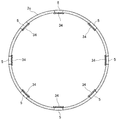
- FIG. 3 is an end view including the peripheral wall 2 c and the closing member 34 obtained by cutting the gas generator 1 in a horizontal direction (a direction orthogonal to the height direction).
- eight gas outlets 5 are arranged along the circumferential direction of the peripheral wall 2c.
- the sizes and shapes of the plurality of gas outlets 5 are all the same.
- the shape and size of each of the plurality of gas outlets 5, the number of the gas outlets 5, and the arrangement interval and arrangement pattern are variously determined in consideration of the output characteristics of the generated combustion gas. Can be changed.
- the bursting pressure of each of the closing members 34 may be made different so that each of the plurality of closing members 34 has a different tensile strength. The tensile strength of the closing member 34 can be changed depending on its thickness and forming material.
- one closing member 34 closes only one gas outlet 5.
- one closing member 34 for closing one gas outlet 5 is independent of another closing member 34 for closing the other gas outlet 5.
- the first igniter 23 operates to burn the first gas generating agent 22 in the first combustion chamber 21.
- combustion gas is generated in the first combustion chamber 21 and the pressure in the first combustion chamber 21 increases.
- the covering region 34 a of the closing member 34 closing the gas outlet 5 is torn, and the inside and the outside of the housing 4 are communicated by the gas outlet 5.
- the combustion gas generated by the first gas generating agent 22 reaches the gas outlet 5 through the filter 32 and is supplied to the outside of the gas generator 1 through the gas outlet 5.
- the closing member 34 is attached to the inner wall surface of the peripheral wall portion 2c, the closing member 34 is easily split by the shearing force, and a stable opening is formed at the gas outlet 5 after the covering region 34a is split. The area can be obtained.
- the second igniter 27 operates to burn the second gas generating agent 26 in the second combustion chamber 25.
- combustion gas is generated in the second combustion chamber 25, and the pressure in the second combustion chamber 25 increases.
- the closing member 37 closing the through hole 17 is torn, and the first combustion chamber and the second combustion chamber are communicated.
- the combustion gas generated by the second gas generating agent 26 reaches the gas outlet 5 through the through hole 17, the first combustion chamber 21 and the filter 32, and is supplied to the outside of the gas generator 1 through the gas outlet 5. Is done.
- the combustion gas is combusted by the combustion of the first gas generating agent 22 by the operation of the first igniter 23 and the combustion of the second gas generating agent 26 by the operation of the second igniter 27. Can be released to the outside.
- the operation timing of each igniter may be determined according to the output characteristics of the combustion gas required for the gas generator 1.
- the covering region 34a is split by shearing force at the early stage of the operation of the gas generator 1, leaving the joining region 34b, so that the time of exposure to high temperature is shorter than the time required for melting. There is no danger of melting.
- the joining region 34b of the closing member 34 remains attached to the inner wall surface of the peripheral wall portion 2c even after the covering region 34a is split, and during the combustion of the first gas generating agent 22 and the second gas generating agent 26, In other words, the bonding region 34b is in a high temperature state.
- the joining region 34b is not provided wider than necessary to ensure the airtightness of the internal space of the housing 4, the possibility that the closing member 34 is melted is reduced.
- the gas discharging port 5 is closed by the closing member 34, and the closing member 34 is melted when the gas generating agents 22 and 26 burn, and is discharged to the outside of the housing 4. Can be suppressed. Further, since the region of the joining region 34b of the closing member 34 is relatively small, the occurrence of wrinkles generated when the temperature changes due to the difference in the expansion rate between the housing 4 and the closing member 34 is reduced. It is possible to prevent a gap from occurring. Further, since the outer shape of the closing member 34 is similar to the shape of the gas discharge port 5, it is possible to maintain the joining force of the closing member 34 to the wall surface of the peripheral wall portion 2c while minimizing the area of the joining region 34b. it can.
- the gas generator can be used as a power source for deploying an airbag of an airbag device mounted on a vehicle or the like, for example.
- the gas generator is used as a power source of the airbag device, it is not preferable for the airbag to release the lump of the molten sealing tape to the outside together with the combustion gas.
- the member that closes the gas outlet 5 has the covering region 34a and the joining region 34b, and the joining region 34b is not provided wider than necessary. The possibility that the member 34 is melted can be reduced. Thereby, when the gas generator 1 according to the present embodiment is used as a power source of the airbag device, it is possible to suppress the release of the molten closing member into the airbag.
- the same member as the closing member 34 can be used for the closing member 37 that closes the through hole 17 that connects the first combustion chamber 21 and the second combustion chamber 25.
- a band-shaped seal tape is used to close the through-hole 17
- a portion of the seal tape that is stuck to the wall surface of the housing wall member 16 is exposed to a high temperature when the gas generating agents 22 and 26 are burned. It can be melted and released with the combustion gas towards the gas outlet 5.
- the melted sealing tape is collected by the filter 32.
- the closing member 37 is the same as the closing member 34.
- the closing member 37 includes a covering region that covers the through hole 17 and a joining region that is joined to the wall surface of the housing wall member 16 and that is formed to surround the covering region adjacent to the covering region.
- the joining area of the closing member 37 has a width of 1 mm or more and 5 mm or less from the periphery of the through hole 17 and is joined to the wall surface so as not to interfere with other joining areas. Since the joining region of the closing member 37 is not provided wider than necessary, the possibility that the closing member 37 is melted can be reduced. Thereby, the gas generator 1 according to the present embodiment can prevent the closing member 37 from melting and releasing to the outside of the housing 4 when the gas generating agents 22 and 26 burn.
- the accommodation wall member 16 has a larger curvature than the peripheral wall portion 2c of the housing 4, when the closure member 37 is attached to the accommodation wall member 16, wrinkles are easily generated in the closure member 37. Since the area of the joining region 34b is minimized, the occurrence of wrinkles can be suppressed.
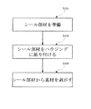
- FIG. 4 is a flowchart showing the sequence of the closing step of the gas outlet 5 by the closing member 34 in the method of manufacturing the gas generator 1 according to the present embodiment.
- the closing step in this embodiment will be described with reference to FIG.
- FIG. 5A is a perspective view showing the seal member 40.
- the seal member 40 has a base material 42 formed in a rectangular shape.
- As the base material 42 an aluminum foil having a thickness of about 50 to 100 ⁇ m is used. Note that a metal foil other than the aluminum foil may be used for the base material 42.
- the adhesive layer 44 is formed on one surface of the base material 42 (the back surface in the state shown in FIG. 5A).
- the adhesive layer 44 serves as a joining surface capable of joining the seal member 40 to the wall surface of the housing 4.
- the base material 42 has a joining surface that can be joined to the wall surface of the housing 4.
- the adhesive layer 44 is covered with a peelable release paper (not shown).
- a plurality of closing members 34 are formed on the base material 42.
- Each of the plurality of closing members 34 is independently formed so as to correspond to each of the plurality of gas outlets 5 provided on the wall surface of the peripheral wall portion 2c.
- a plurality of closing members 34 each having a diameter larger by 1 mm to 5 mm than each diameter of the gas discharge ports 5 are formed on the base material 42.
- the closing member 34 is formed by making a cut 39 that does not penetrate from the surface of the base material 42 (the surface opposite to the surface on which the adhesive layer 44 is formed) to the adhesive layer 44 shown in FIG. Is done.
- a plurality of closing members 34 are formed from one sealing member 40, and the outer shape of the closing members 34 can be defined by the cuts 39.
- each of the plurality of closing members 34 is formed to be bonded to the base 42 at a strength lower than the strength of the base 42.
- the seal member 40 on which the plurality of closing members 34 are formed is prepared (Step S101).
- step S102 following step S101, the seal member 40 is attached to the housing.
- the step of attaching the prepared seal member 40 to the wall surface of the housing 4 will be described with reference to FIG.
- FIG. 5B shows a part of the peripheral wall portion 2c and only four gas outlets 5 formed on the wall surface of the peripheral wall portion 2c for explanation.
- a plurality of closing members 34 are formed in the seal member 40 so as to correspond to the arrangement pattern of the plurality of gas outlets 5.
- the outer shape of the closing member 34 and the gas outlet 5 are both circular.
- the seal member 40 is attached to the wall surface of the peripheral wall portion 2c so that each of the plurality of closing members 34 formed on the seal member 40 corresponds to each of the plurality of gas outlets 5. wear. More specifically, after positioning the seal member 40 with respect to the wall surface of the peripheral wall portion 2c so that the center of each of the plurality of closing members 34 coincides with the center of each of the plurality of gas outlets 5, the sealing member 40 is attached to the wall.
- the outer periphery of the predetermined width of the closing member 34 formed on the base material 42 is in a state of being joined to the wall surface of the peripheral wall portion 2c.
- a region that is joined to the peripheral wall 2c of the closing member 34 is a joined region 34b.
- step S103 the base material 42 is peeled off from the seal member 40 attached to the wall surface of the peripheral wall portion 2c. Since each of the joining regions 34b of the plurality of closing members 34 formed on the base material 42 is joined to the wall surface of the peripheral wall portion 2c, each of the closing members 34 is left on the wall surface of the peripheral wall portion 2c.
- the substrate 42 is peeled off.
- Each of the plurality of closing members 34 is bonded to the base 42 at a strength lower than the strength of the base 42 by the cuts 39, and thus, for example, while pressing each of the plurality of closing members 34, By peeling the base material 42, the base material 42 can be peeled while the plurality of closing members 34 are left on the wall surface of the peripheral wall part 2c.
- FIG. 5C shows a state after the base material 42 has been peeled off.
- Each of the plurality of gas outlets 5 is closed by each of the plurality of closing members 34 remaining on the wall surface of the peripheral wall portion 2c.
- each of the plurality of closing members 34 is joined to the wall surface of the peripheral wall portion 2c while peeling the base member 42 from the sealing member 40 attached to the wall surface of the peripheral wall portion 2c.
- each of the plurality of gas discharge ports 5 is closed while leaving each of the plurality of closing members 34 on the wall surface of the peripheral wall portion 2c.
- the base material 42 is peeled off from the sealing member 40, so that each of the plurality of gas discharge ports 5 is closed by each of the plurality of closing members 34. Is done.
- the time required for attaching the closing member 34 can be reduced, and the step of closing the gas outlet 5 can be completed in a short time.
- the gas generator 1 manufactured according to the present embodiment since the joining area 34b is not provided wider than necessary to ensure the airtightness of the internal space of the housing 4, the gas generator 1 is not formed so wide that it is closed. Since the member 34 can be attached, the possibility that the closing member 34 is melted can be reduced, and the closing member 34 melts and burns out of the gas generator 1 when the gas generating agents 22 and 26 burn. Can be suppressed.
- FIG. 6A is a plan view showing two gas outlets 5 and two closing members 34 provided on the wall surface of the upper shell 2 defining the first combustion chamber 21 in an enlarged manner.
- FIG. 6B is a sectional view showing the upper shell 2 and the closing member 34 extracted from the sectional view in the height direction of the gas generator 1 shown in FIG.
- a region surrounded by a dotted line is the gas outlet 5 as in FIGS. 2A and 2B.
- connection member 36 is formed integrally with the plurality of closing members 34 using the same material as the closing member 34.
- the connection member 36 has a horizontally long rectangular shape in which the circumferential direction of the housing 4 is the longitudinal direction.
- the connecting member 36 has an adhesive layer formed on one surface, and is attached to the wall surface of the housing 4 with the adhesive layer.
- the width w2 of the connecting member 36 is smaller than the width w3 of the closing member 34.
- the width w2 of the connection member 36 is a direction substantially orthogonal to the arrangement direction of the closing member 34 and the connection member 36.
- the width w2 of the connection member 36 is the length of the connection member 36 in the lateral direction.
- the arrangement direction of the closing member 34 and the connection member 36 is the circumferential direction of the housing 4.
- the width w3 of the closing member 34 is a length in a direction substantially orthogonal to the arrangement direction of the closing member 34 and the connecting member 36.
- the outer shape of the closing member 34 has a circular shape.
- the width w3 of the member 34 is the diameter of the closing member 34.
- the width w3 when the closing member 34 has a polygonal shape is a length from one end passing through the center of the polygon to the other end.
- each of the plurality of gas outlets 5 is arranged along the circumferential direction of the housing 4, and each of the plurality of closing members 34 is adjacent to each other. Are connected by the connecting member 36 to be integrated.
- Each of the plurality of closing members 34 is connected to the wall surface of the peripheral wall 2c by the connecting region 34b and the connecting member 36.
- the gas generator 1 according to the present modification has eight gas outlets 5 and a closing member 34 as in the first embodiment. In this case, for example, four closing members 34 may be connected and integrally formed by three connecting members, and eight gas outlets 5 may be closed using two of them.
- the closing member 34 can be attached to the wall surface of the housing 4 by the joining region 34b and the connecting member 36, so that the closing member 34 is more firmly fixed to the wall surface of the housing 4. be able to. Further, according to the gas generator 1 according to the present modification, since the width of the connecting member 36 is smaller than the width of each of the plurality of closing members 34, the area of the closing member 34 and the connecting member 36 is reduced by the area of the band-shaped seal tape. Since the area of the closing member 34 and the connecting member 36 that may be melted can be reduced, the gas discharge port 5 can be closed by the closing member 34 and the closing member 34 and the connecting member 36 can be melted.
- connection member 36 It is possible to prevent the connection member 36 from being melted during the combustion of the gas generating agents 22 and 26 and being released to the outside of the gas generator 1. Further, since each of the plurality of closing members 34 is connected and integrally formed by the connecting member 36, the plurality of closing members 34 can be easily handled. Further, by utilizing the flexibility of the connecting member 36, distortion or displacement of the closing member 34 which may occur at the time of attaching the closing member 34 is hardly generated, and a band-shaped sealing tape having a certain width is used for closing the gas discharge port 5. As compared with the case of using, the occurrence of wrinkles after the closing member 34 is pasted and the generation of a gap between the closing member 34 and the wall surface of the peripheral wall portion 2c can be suppressed.
- a closing member 34 may be attached to an outer wall surface of the housing 4 to close the gas outlet 5.
- the gas generator 1 having such a configuration is used as a drive source of an airbag device, the airbag is folded near the gas outlet 5 before the gas generator 1 is operated.
- the high-temperature combustion gas may hit the outer peripheral surface of the housing 4 near the gas outlet 5.
- the joining region 34b of the closing member 34 joined to the outer peripheral surface of the peripheral wall portion 2c of the housing 4 may melt.
- the joining region 34b is not provided wider than necessary, the joining region 34b is melted.
- the gas generator 1 closes the gas discharge port 5 with the closing member 34 and suppresses the closing member 34 from melting and releasing to the outside of the gas generator 1 when the gas generating agents 22 and 26 burn. Can be.
- the gas generator 1 having such a configuration can of course apply the step of closing the gas outlet 5 shown in FIGS. 4 and 5 and the closing member 34 and the connecting member 36 shown in FIG.
- FIG. 7 is a sectional view in the height direction of the gas generator 101 in the present embodiment.
- the gas generator 101 shown in FIG. 7 only one combustion chamber 121 and one igniter 123 are housed in a housing 104 formed by welding and fixing with a flange portion having an upper shell 102 and a lower shell 103, respectively.
- a single-type gas generator As a single-type gas generator.
- the technology of the present disclosure is of course also applicable to a single type gas generator.
- An igniter 123 is arranged at the center of the internal space of the housing 104.
- the lower end of the igniter 123 is joined to the bottom of the lower shell 103, and the upper end of the igniter 123 is in contact with the top of the upper shell 102. Accordingly, an annular space surrounding the igniter 123 is formed in the internal space of the housing 104.
- the space forms a combustion chamber 121, and the combustion chamber 121 is filled with a gas generating agent 122.
- the gas generating agent 122 is filled in a state in which the gas generating agent 122 is pressed against the bottom surface of the lower shell 103, the filter 132, and the like by the urging force of the cushion 131 so as not to vibrate unnecessarily in the first combustion chamber 121.
- An annular filter 132 is arranged between the housing 4 and the gas outlet 50 formed on the wall surface of the housing 4 that defines the combustion chamber 121.
- the filter 132 may be the same as the filter 32 of the first embodiment.
- the gas generator 101 includes an igniter 123 as an ignition device.
- the ignition device may be constituted only by the igniter 123 or may be constituted by including the igniter 123 and the transfer charge.
- the gas exhaust port 50 is closed from the inside of the housing by the closing member 134 before the gas generator 101 is operated.
- the closing member 134 is attached to the inner wall surface of the upper shell 102 so as to close the gas outlet 50 from the inside of the housing 104. Since the configurations of the gas outlet 50 and the closing member 134 are the same as those of the gas outlet 5 and the closing member 34 in the first embodiment, detailed description will be omitted.
- the closing member 134 melts when the gas generating agent 122 burns and is discharged to the outside of the gas generator 101. Can be suppressed.
- the gas discharge port closing step shown in FIGS. 4 and 5 may be applied. Further, in the gas generator 101, the closing member 34 and the connecting member 36 in the modification of the first embodiment may be applied. Further, in the gas generator 101, the closing member 134 may be attached to the outer wall surface of the housing 104 to close the gas outlet 50.
- the gas generator according to the above embodiment and the modified example has a disk shape whose length in the axial direction (height direction) is shorter than the outer diameter in a top view.
- the technology of the present disclosure may be applied to a gas generator having a cylindrical shape whose outer diameter is longer than an outer diameter in a top view.
- a gas generator having a cylindrical shape a plurality of gas outlets are formed in a housing, and each of the plurality of gas outlets is arranged in a plurality in the axial direction of the housing.
- each of the plurality of gas outlets may be closed by using a plurality of the closing members of the above embodiment.
- the gas outlet may be closed by the closing step shown in FIGS. 4 and 5, or the gas outlet may be closed by the closing member 34 shown in FIG. Of course, it is good.
Landscapes
- Physics & Mathematics (AREA)
- Fluid Mechanics (AREA)
- Engineering & Computer Science (AREA)
- Mechanical Engineering (AREA)
- Air Bags (AREA)
Abstract
ガス発生器は、ハウジングと、ハウジング内に収容された点火装置により燃焼されるガス発生剤が充填された燃焼室と、燃焼室を画定する壁面に設けられ、該燃焼室の内部と外部とを連通する複数のガス排出口と、複数のガス排出口の各々を閉塞する複数の閉塞部材と、を備える。複数の閉塞部材の各々は、ガス排出口を被覆する被覆領域と、ハウジングの壁面に接合する領域であって、被覆領域に隣接して該被覆領域を囲むように形成される接合領域と、を有する。複数の閉塞部材の各々の接合領域は、対応するガス排出口の周縁から1mm以上5mm以下の範囲の幅で、且つ他の接合領域と干渉しないように、ハウジングの壁面に接合する。
Description
本発明は、点火器での火薬燃焼により、ガス発生剤を燃焼させて燃焼ガスを発生させるガス発生器に関する。
ガス発生剤を燃焼させて発生した燃焼ガスを所望の動作を実現するための動力源として供給するガス発生器が知られている。ガス発生器は、点火器の作動により、ハウジング内でガス発生剤を燃焼させて発生させた燃焼ガスをハウジングに設けられたガス排出口から外部に供給する。このような、ガス発生器においては、点火器の作動前にガス排出口から湿気を含んだ外気がハウジング内部に侵入してガス発生剤が湿らないようにガス排出口が閉塞されている。
特許文献1には、ハウジングを構成する上部シェルの周壁部に複数のガス噴出口が設けられたガス発生器が記載されている。当該ガス発生器では、複数のガス噴出口が一定幅の帯状の1枚のシールテープによって閉塞されている。シールテープは、ガス噴出口を閉塞するように上部シェルの周壁部の内周面に貼り付けられている。当該シールテープによってハウジング内の燃焼室の気密性が確保されている。また、ガス発生器の点火器の作動時には、ガス発生剤の燃焼に伴ったハウジング内部の圧力上昇に伴い、ガス噴出口を閉塞している部分のシールテープが開裂することでガス噴出口が開口して、燃焼ガスが外部に供給される。
複数のガス噴出口が、ハウジングの周壁部に並んで設けられている場合、1枚の一定幅の帯状のシールテープで複数のガス噴出口が閉塞され得る。また、帯状のシールテープは、ガス噴出口を閉塞した上で幅に余裕があるように形成されている。このため、シールテープは、ハウジングの周壁部の内周面におけるガス噴出口が形成されている領域以外にも貼り付けられている。シールテープによって覆われている全領域のうち、全てのガス噴出口の開口面積よりも、ガス噴出口が形成されていない周壁部の面積の方が広くなっている。
ガス発生器の点火器が作動してガス発生剤が燃焼すると、シールテープが高温に晒されて、当該シールテープが溶融する虞がある。シールテープの全領域のうち、実際にガス噴出口を閉塞している部分は、ガス発生器の作動初期に開裂するので、高温に晒される時間が溶融するのに必要な時間よりも短くなり溶融する虞はないが、当該シールテープの全領域のうちハウジングの周壁部に貼り付いている部分は、ガス発生器の作動時に高温に晒される時間が長くなり、溶融して燃焼ガスと共にガス発生器の外部に放出されてしまう虞がある。帯状のシールテープは、ガス噴出口を閉塞する部分よりも、ガス噴出口が形成されていない内周面に貼り付いている面積の方が広いので、ガス発生剤の燃焼時において、溶融する虞のない部分よりも溶融してしまう虞のある部分を相対的に多く含んでいる。このため、ガス発生剤の燃焼時に溶融したシールテープを外部に放出してしまう虞が高くなってしまっている。溶融してガス発生器から放出されたシールテープは、燃焼ガスを動力源とする装置にとって好ましくない。
本件開示の技術は、上記した問題に鑑み、ガス発生器のガス排出口を閉塞部材で閉塞しつつ、閉塞部材がガス発生剤の燃焼時に溶融してガス発生器の外部に放出されるのを抑制し得る技術を提供することを目的とする。
上記課題を解決するために、本件開示のガス発生器は、ガス排出口を被覆する被覆領域と、燃焼室を画定する壁面に接合する領域であって、被覆領域に隣接して該被覆領域を囲むように形成される接合領域を有する閉塞部材でガス排出口を閉塞する構成を採用した。このような構成により、ガス排出口を閉塞しつつ、ガス発生器の外部に溶融した閉塞部材が放出されるのを抑制することが可能となる。
具体的には、本件開示のガス発生器は、ハウジングと、前記ハウジング内に収容された点火装置により燃焼されるガス発生剤が充填された燃焼室と、前記燃焼室を画定する壁面に設けられ、該燃焼室の内部と外部とを連通する複数のガス排出口と、前記複数のガス排出口の各々を閉塞する複数の閉塞部材と、を備える。そして、前記複数の閉塞部材の各々は、前記ガス排出口を被覆する被覆領域と、前記壁面に接合する領域であって、前記被覆領域に隣接して該被覆領域を囲むように形成される接合領域と、を有する。さらに、前記複数の閉塞部材の各々の前記接合領域は、対応する前記ガス排出口の周縁から1mm以上5mm以下の範囲の幅で、且つ他の接合領域と干渉しないように、前記壁面に接合する。
本件開示のガス発生器は、点火装置の作動により、ガス発生剤を燃焼させて、燃焼ガスを発生する。そして、ガス発生器は、燃焼ガスを所定の駆動源として供給する。ここで、ガス発生器は、点火装置の作動前においては、燃焼室内に外気が侵入しないように、ガス排出口が閉塞部材で閉塞されている。これにより、燃焼室内の気密性が確保されている。点火装置が作動すると、燃焼ガスの発生により燃焼室内の圧力が上昇し、閉塞部材の被覆領域が開裂して、燃焼室の外部と内部とが連通され、燃焼ガスがガス排出口を通って、外部に供給される。閉塞部材の被覆領域は、点火装置の作動初期に開裂するので、高温に晒される時間が溶融するのに必要な時間よりも短くなり溶融する虞はない。一方、閉塞部材の接合領域は、被覆領域が開裂した後も、燃焼室を画定する壁面に接合したままとなり、ガス発生剤の燃焼中には、接合領域は高温状態におかれる。
そこで、本件開示のガス発生器では、複数の閉塞部材の各々の接合領域は、対応するガス排出口の周縁から1mm以上5mm以下の範囲の幅で燃焼室を画定する壁面に接合している。接合領域を燃焼室の気密性を確保するのに必要以上に広く設けていないため、閉塞部材が溶融してしまう可能性を低減することができる。これにより、本件開示のガス発生器は、ガス排出口を閉塞部材で閉塞しつつ、閉塞部材がガス発生剤の燃焼時に溶融して外部に放出されるのを抑制することができる。
燃焼室はハウジングにより画定されていてもよいし、ハウジング内に配置された内隔壁により画定されていてもよい。燃焼室がハウジングにより画定される場合にはガス排出口は当該ハウジングの壁面に設けられる。また、燃焼室がハウジング内に配置された内隔壁により画定される場合には、ガス排出口は当該内隔壁を貫通するにように設けられる。
また、上記のガス発生器において、前記複数の閉塞部材の各々の外郭形状は、前記複数のガス排出口の各々の形状と相似であってもよい。このような構成により、閉塞部材をガス排出口に対応させて配置する場合に、閉塞部材の位置決めを容易にすることができる。また、接合領域の面積を最小限にしつつ、閉塞部材の壁面に対する接合力を維持することができる。なお、閉塞部材の外郭形状及びガス排出口の形状は、円形状、多角形状、楕円形状等であってもよい。
また、上述までのガス発生器において、前記複数の閉塞部材の各々は、前記燃焼室側の前記壁面に取り付けられていてもよい。このような構成の場合、点火装置が作動してガス発生剤が燃焼すると、閉塞部材の接合領域は高温に晒されるが、接合領域を燃焼室の気密性を確保するのに必要以上に広く設けていないため、溶融する虞のある接合領域を小さくして、閉塞部材が溶融してしまう可能性を低減することができる。また、閉塞部材がせん断力により開裂しやすくなり、被覆領域が開裂した後のガス排出口において安定した開口面積を得ることができる。
また、上述までのガス発生器において、前記複数の閉塞部材の各々の中心位置は、前記複数のガス排出口の各々の中心位置と一致していてもよい。このような構成により、閉塞部材の接合領域の幅を一定にすることができ、ガス排出口の周縁全体を均一に封止することができる。
また、上述までのガス発生器において、前記複数のガス排出口の各々は、前記ハウジングの周方向に沿って配置され、前記複数の閉塞部材の各々は、隣り合う該閉塞部材同士が接続部材で接続されて一体となった状態で該複数の閉塞部材の各々が有する前記接合領域と該接続部材によって前記壁面と接合し、前記接続部材の幅は、前記複数の閉塞部材の各々の幅よりも小さくてもよい。このような構成によれば、接合領域と接続部材とにより閉塞部材を取り付けることができるため、閉塞部材をより強固に固定することができる。また、接続部材の幅が複数の閉塞部材の各々の幅よりも小さいため、閉塞部材及び接続部材の面積を帯状のシールテープの面積よりも小さくするこができ、溶融してしまう虞のある閉塞部材及び接続部材の面積を小さくすることができるので、閉塞部材及び接続部材がガス発生剤の燃焼時に溶融して外部に放出されるのを抑制することができる。さらに、接続部材の柔軟性を利用して、閉塞部材の貼り付け時に発生し得る当該閉塞部材の歪みやずれを発生し難くし、ガス排出口の閉塞に一定幅の帯状のシールテープを使用した場合と比較して、閉塞部材を貼り終えた後の皺や壁面との間の隙間の発生を抑制することができる。
また、上述までのガス発生器において、前記複数の閉塞部材は、シールテープであってもよい。例えば、閉塞部材には、アルミニウム箔やその他の金属箔の片面に粘着層が形成されたシールテープが用いられてもよい。
ここで、本件開示の技術をガス発生器の製造方法の側面から捉えることができる。すなわち、本件開示の技術は、上述までのガス発生器の製造方法である。具体的には、一方の面が前記壁面に接合可能な接合面を有する基材に、前記複数の閉塞部材が各々独立して、該壁面に設けられた前記複数のガス排出口の各々の並びに対応するように形成されるとともに、該複数の閉塞部材の各々は該基材に対して、該基材の強度よりも低い強度で結合されて形成される、シール部材を準備し、前記シール部材に形成された前記複数の閉塞部材の各々を、前記複数のガス排出口の各々に対応するように、該シール部材を前記壁面に貼り付け、前記壁面に貼り付けられた前記シール部材から前記基材を剥がしながら、前記複数の閉塞部材の各々が有する前記接合領域が該壁面に接合した状態で、該複数の閉塞部材の各々を該壁面に残して前記複数のガス排出口の各々を閉塞する。
上記ガス発生器の製造方法では、1枚のシール部材を壁面に貼り付けた後、シール部材から基材を剥がすことにより、複数のガス排出口の各々が複数の閉塞部材の各々により閉塞される。これにより、閉塞部材の取り付けにかかる時間を短縮することができ、短時間でガス排出口を閉塞する工程を終了することができる。
本件開示の技術によれば、ガス発生器のガス排出口を閉塞部材で閉塞しつつ、閉塞部材がガス発生剤の燃焼時に溶融してガス発生器の外部に放出されるのを抑制することができる。
以下に、図面を参照して本件開示の実施形態に係るガス発生器について説明する。なお、以下の実施形態の構成は例示であり、本件開示の技術はこれらの実施の形態の構成に限定されるものではない。
<実施例1>
図1は、実施例1に係るガス発生器1の高さ方向の断面図である。ガス発生器1は、上部シェル2及び下部シェル3で形成されるハウジング4内に充填されたガス発生剤を燃焼させて、燃焼ガスを放出するように構成されている。なお、ガス発生器1は、後述するように2つの燃焼室が上下に配置され、各燃焼室に、対応する点火器及びガス発生剤を配置した、いわゆるデュアルタイプのガス発生器である。ここで、上部シェル2は周壁部2cと頂面部2dを有し、これらにより凹状の内部空間を形成する。頂面部2dは、後述の下部シェル3の底面部3bとともに、上面視で概ね円形状を有している。周壁部2c及び後述の下部シェル3の周壁部3aは、それぞれ頂面部2d、底面部3bの周囲を囲み、各面部から概ね垂直に延在した環状の壁面を形成している。上部シェル2の内部空間は、後述するように第1ガス発生剤22が充填される第1燃焼室21となる。周壁部2cの一端側に頂面部2dが接続し、その他端側は上部シェル2の開口部となる。そして、周壁部2cの当該他端側には、当該開口部から順に、嵌合壁部2a、突き当て部2bが設けられている。嵌合壁部2aによる内部空間の半径は、頂面部2d寄りの周壁部2cによる内部空間の半径より大きく形成され、嵌合壁部2aは、突き当て部2bを介して周壁部2cへと繋がっている。
図1は、実施例1に係るガス発生器1の高さ方向の断面図である。ガス発生器1は、上部シェル2及び下部シェル3で形成されるハウジング4内に充填されたガス発生剤を燃焼させて、燃焼ガスを放出するように構成されている。なお、ガス発生器1は、後述するように2つの燃焼室が上下に配置され、各燃焼室に、対応する点火器及びガス発生剤を配置した、いわゆるデュアルタイプのガス発生器である。ここで、上部シェル2は周壁部2cと頂面部2dを有し、これらにより凹状の内部空間を形成する。頂面部2dは、後述の下部シェル3の底面部3bとともに、上面視で概ね円形状を有している。周壁部2c及び後述の下部シェル3の周壁部3aは、それぞれ頂面部2d、底面部3bの周囲を囲み、各面部から概ね垂直に延在した環状の壁面を形成している。上部シェル2の内部空間は、後述するように第1ガス発生剤22が充填される第1燃焼室21となる。周壁部2cの一端側に頂面部2dが接続し、その他端側は上部シェル2の開口部となる。そして、周壁部2cの当該他端側には、当該開口部から順に、嵌合壁部2a、突き当て部2bが設けられている。嵌合壁部2aによる内部空間の半径は、頂面部2d寄りの周壁部2cによる内部空間の半径より大きく形成され、嵌合壁部2aは、突き当て部2bを介して周壁部2cへと繋がっている。
また、下部シェル3は周壁部3aと底面部3bを有し、これらにより凹状の内部空間を形成する。当該内部空間は、第2ガス発生剤26が充填される第2燃焼室25となる。周壁部3aの一端側に底面部3bが接続し、その他端側は下部シェル3の開口部となる。そして、周壁部3aによる内部空間の半径は、上部シェル2の周壁部2cによる内部空間の半径と概ね同じである。下部シェル3の底面部3bには、第1点火器23と第2点火器27がそれぞれ固定される孔が設けられている。
更に、ハウジング4内には、上部シェル2と下部シェル3との間に分割壁10が配置されている。分割壁10は、終端部15と、その終端部15に繋がりハウジング4内を概ね上下の空間に分割する分割壁部14と、分割壁部14に繋がり後述する収容壁部材(収容壁)16に沿って延在する周壁部13と、収容壁部材16の開口部を一部覆うように配置される端部12を有する。なお、端部12は、貫通孔11を形成している。また、下部シェル3の底面部3bに取り付けられた第1点火器23の周囲を、その高さ方向に囲むように、筒状の収容壁部材16が底面部3bに設けられている。この収容壁部材16の上方の開口部は、上記分割壁10の端部12によって覆われている。また、収容壁部材16には貫通孔17が設けられており、貫通孔17は、分割壁10により分割されて形成される2つの空間(第1燃焼室21と第2燃焼室25)を連通する。貫通孔17は第1点火器23配置側から閉塞部材37で閉塞されている。閉塞部材37には、閉塞部材34と同じものが用いられる。
第1点火器23の周囲であって、筒状の収容壁部材16の内部には、伝火薬が充填されていてもよい。伝火薬には、例えばニトログアニジン(34重量%)、硝酸ストロンチウム(56重量%)を含む粒状や円柱状のものを用いることができる。また、伝火薬が充填される場合には、貫通孔11がアルミニウムテープ等で塞がれ、伝火薬と第1ガス発生剤22との混在が防止される。本実施例に係るガス発生器1は、点火装置として第1点火器23を備えている。点火装置は、第1点火器23のみで構成されていてもよいし、第1点火器23と伝火薬とを含んで構成されていてもよい。
そして、このように下部シェル3上に分割壁10が取り付けられた状態で、上方より上部シェル2が更に取り付けられる。上記の通り、上部シェル2の嵌合壁部2aによる内部空間の半径は、周壁部2cによる内部空間の半径より大きく形成されているため、上部シェル2は、その突き当て部2bが分割壁10の終端部15に突き当てられるまで、下部シェル3に対して嵌め込まれる。なお、ハウジング4において、上部シェル2と下部シェル3の嵌合部位や接触部位は、内部に充填されるガス発生剤の防湿等のために好適な接合方法(例えば、溶接等)により接合される。
このようにハウジング4においては、分割壁10によってその内部空間が概ね上下に2つの空間に分割されることになる。ハウジング4の内部空間のうち上部シェル2と分割壁10によって画定される第1燃焼室21には、第1点火器23、第1ガス発生剤22が配置され、下部シェル3と分割壁10によって画定される第2燃焼室25には、第2点火器27、第2ガス発生剤26が配置されることで、ガス発生器1は2つの第1点火器23、第2点火器27を備えるデュアルタイプのガス発生器として構成されている。なお、第1点火器23と第2点火器27はともに下部シェル3の底面部3b上に固定されており、そのため、第1点火器23は、第1点火器23の側方が収容壁部材16に囲まれた状態となっている。
ここで、第1燃焼室21では、収容壁部材16の内部空間(収容壁部材16の内側と、下部シェル3の底面部3bと、によって画定される空間であって、上方に開口している空間)には第1点火器23が収容され、その上方の空間に第1ガス発生剤22が充填されることになるが、その第1ガス発生剤22を取り囲むように環状のフィルタ32が配置されている。このとき第1ガス発生剤22は、第1燃焼室21内で不要に振動しないようにクッション31の付勢力によりフィルタ32、分割壁部14等に抑えつけられた状態で充填されている。第1ガス発生剤22は、比較的燃焼温度の低いガス発生剤を使用している。第1ガス発生剤22の燃焼温度は、1000~1700℃の範囲にあることが望ましく、例えば、硝酸グアニジン(41重量%)、塩基性硝酸銅(49重量%)及びバインダーや添加物からなる、単孔円柱状のものを用いることができる。なお、収容壁部材16の内部空間には、第1ガス発生剤22と組成が異なるガス発生剤が充填されてもよい。この場合、収容壁部材16の内部空間に充填されるガス発生剤の組成は、第1ガス発生剤22の着火を助長するため、燃焼温度が第1ガス発生剤22よりも高くなるように構成され得る。
なお、フィルタ32は、ステンレス鋼製平編の金網を半径方向に重ね、半径方向及び軸方向に圧縮して形成されており、第1ガス発生剤22による燃焼ガスを冷却し、その燃焼残渣を捕集する。フィルタ32として、その他に針金を心棒に多層に巻いて形成された巻線タイプの構造のものを採用してもよい。なお、フィルタ32は、第2燃焼室25に充填された第2ガス発生剤26の燃焼残渣も捕集する。また、上部シェル2の周壁部2cとフィルタ32との間に形成された間隙33により、フィルタ32の周囲に半径方向断面に環状のガス通路が形成される。この間隙33により、燃焼ガスはフィルタ32の全領域を通過し、フィルタ32の有効利用と燃焼ガスの効果的な冷却・浄化が達成される。間隙33を流れる燃焼ガスは、周壁部2cに設けられたガス排出口5に至る。また、ハウジング4内に外部より湿気を含んだ外気が侵入するのを阻止するために、ガス発生器1の作動前では、閉塞部材34によりハウジングの内部からガス排出口5が閉塞されている。本実施例において、第1燃焼室21を画定する周壁部2cの壁面に複数のガス排出口5が設けられており、複数のガス排出口5の各々が複数の閉塞部材34の各々により閉塞されている。閉塞部材34は、ハウジング4の内部からガス排出口5を閉塞するように上部シェル2の周壁部2cの内壁面に取り付けられている。また、閉塞部材34は、フィルタ32を介して第1燃焼室21に晒されて配置されている。なお、閉塞部材34の詳細について後述する。
また、第2燃焼室25では、下部シェル3の底面部3bに固定された第2点火器27に対応して、第2ガス発生剤26が充填されている。そして、第2ガス発生剤26も、第2燃焼室25内で不要に振動しないようにクッション35によって付勢された状態で充填されている。また、第2ガス発生剤26にも、第1ガス発生剤22と同様に、硝酸グアニジン(41重量%)、塩基性硝酸銅(49重量%)及びバインダーや添加物からなる、単孔円柱状のものを用いることができる。
また、第2点火器27の周囲には、伝火薬が充填されていてもよい。伝火薬には、例えばニトログアニジン(34重量%)、硝酸ストロンチウム(56重量%)を含む粒状や円柱状のものを用いることができる。また、伝火薬が充填される場合には、伝火薬と第2ガス発生剤26とが混在しないように伝火薬と第2ガス発生剤26とを隔離する所定部材が配置される。本実施例に係るガス発生器1は、点火装置として第2点火器27を備えている。点火装置は、第2点火器27のみで構成されていてもよいし、第2点火器27と伝火薬とを含んで構成されていてもよい。
本実施例では、燃焼室21、25はハウジング4により画定されている。なお、ハウジング104内に環状の内隔壁を有する部材が配置され、内隔壁内にガス発生剤21、26が充填されて燃焼室21、25は当該内隔壁で画定されてもよい。この場合、ガス排出口は当該内隔壁を貫通するにように設けられ、当該内隔壁に閉塞部材34が取り付けられる。
このような構成により、ガス発生器1では、第1点火器23の作動による第1ガス発生剤22の燃焼と、第2点火器27の作動による第2ガス発生剤26の燃焼とによって、外部への燃焼ガスの放出の形態を多様に調整することができる。また、ガス発生器1は、比較的多量の燃焼ガスを生成し、外部に放出することができる。
次に、図1を参照しつつ、図2及び図3を用いて、ガス排出口5及び閉塞部材34について詳細に説明する。図2(a)は、第1燃焼室21を画定する上部シェル2の壁面に設けられたガス排出口5及び閉塞部材34を1つずつ抜き出して拡大して示す平面図である。図2(b)は、図1に示すガス発生器1の高さ方向の断面図から上部シェル2と閉塞部材34を抜き出して示す断面図である。図2(a)、(b)において、点線で囲まれた領域がガス排出口5である。ガス排出口5は、ハウジング4の内部と外部とを連通しており、ガス発生剤22、26の燃焼時に燃焼ガスをハウジング外部に供給するために設けられている。本実施例では、複数のガス排出口5の各々は、上部シェル2の周方向に沿って配置されている。また、複数のガス排出口5の各々は、同じ大きさで且つ同じ形状で形成されている。本実施例では、ガス排出口5は、円形状に形成されている。なお、ガス排出口5は、楕円形状や多角形状に形成されていてもよい。また、複数のガス排出口5の各々は、均等な間隔を設けて配置されている。
また、図2(a)、(b)に示すように、1つのガス排出口5は、1つの閉塞部材34により閉塞されている。本実施例では、複数の閉塞部材の各々は、周壁部2cの燃焼室21側の壁面(内壁面)に取り付けられている。閉塞部材34は、ガス排出口5を被覆する被覆領域34aと、上部シェル2の周壁部2cの壁面に接合する領域であって、被覆領域34aに隣接して被覆領域34aを囲むように形成される接合領域34bとを有している。図2(a)、(b)において、点線で囲まれた領域が被覆領域34aであり、点線の外側であって実線で囲まれた領域が接合領域34bである。被覆領域34aは、ガス排出口5と重なる領域であって、ガス排出口5を被覆する部分である。接合領域34bは、閉塞部材34を周壁部2cに取り付ける際の取り付け代となる部分である。接合領域34bが周壁部2cの壁面に接合することで、ガス排出口5の周縁全体が封止される。これにより、閉塞部材34は、ガス排出口5を閉塞している。
閉塞部材34は、ガス排出口5を介してハウジング4内部に外気が侵入しないようにするために取り付けられている。閉塞部材34によってハウジング4の内部空間の気密性が確保されている。このため、閉塞部材34の接合領域34bによりガス排出口5の周縁全体が確実に封止される必要がある。接合領域34bの幅w1を狭くしすぎると、ガス排出口5の周縁全体を確実に封止することができない虞がある。このため、本実施例では、図2(a)に示す、閉塞部材34の接合領域34bの幅w1を1mm以上に設定した。より詳細には、接合領域34bの幅w1の下限値は、有効数字2桁で0.95mmに設定した。なお、接合領域34bの幅w1は、ガス排出口5の周縁から閉塞部材34の周縁までの長さである。また、接合領域34bは、ガス発生器1の点火器23、27の作動時にガス発生剤22、26が燃焼するとハウジング4内部で高温に晒される時間が長くなる部分である。接合領域34bの幅w1をガス排出口5の周縁全体を封止するのに必要な幅よりも広くしすぎると、ガス発生器1の作動時に溶融する虞のある部分を必要以上に広げることになり、好ましくない。このため、本実施例では、接合領域34bの幅w1を5mm以下に設定した。より詳細には、接合領域34bの幅w1の上限値は、有効数字2桁で5.4mmに設定した。また、接合領域34bに隣接する他の閉塞部材の接合領域34bが重なってしまうと当該接合領域34bの接合性が低下してしまったり、接合領域34b同士が重なる部分の端部に隙間が生じてしまったりして、ガス排出口5の封止性が低下してしまう虞がある。このため、本実施例では、一の閉塞部材34の接合領域34bは、他の閉塞部材34の接合領域34bと重なったり、接触したりしないように、取り付けられている。即ち、一の閉塞部材34の接合領域34bは、他の閉塞部材34の接合領域34bと干渉しないように周壁部2cの壁面に配置されている。このように、本実施例では、複数の閉塞部材34の各々は、隣り合う閉塞部材34と独立して配置されている。
閉塞部材34には、例えば、50~100μm程度の厚さのアルミニウム箔の片面に粘着層が形成されたシールテープが用いられる。なお、閉塞部材34には、アルミニウム箔以外の金属箔の片面に粘着層が形成されたシールテープが用いられてもよいし、金属箔の片面に接着剤を塗布して当該金属箔をハウジング4に貼り付けて閉塞部材34としてもよい。
本実施例では、閉塞部材34の外郭形状は、円形状に形成されている。閉塞部材34の外郭形状は、ガス排出口5の形状と相似である。また、閉塞部材34は、ガス排出口5と中心が一致するように配置されている。言い換えると、閉塞部材34は、ガス排出口5と同心円状に配置されている。このため、接合領域34bの幅w1は、ガス排出口5の周方向に沿って一定となる。接合領域34bの幅w1を一定にすることで、ガス排出口5の周縁全体を均一に封止することができる。閉塞部材34の外郭形状は、ガス排出口5と相似でなくてもよく、例えば、楕円形状や多角形状に形成されていてもよい。また、接合領域34bの幅w1は、ガス排出口5の周方向に沿って一定でなくてもよく、1mm(0.95mm)以上5mm(5.4mm以下)であればよい。
図3は、ガス発生器1を水平方向(高さ方向に直交する方向)で切断した周壁部2c及び閉塞部材34を含む端面図である。本実施例に係るガス発生器1において、複数のガス排出口5の各々は、周壁部2cの周方向に沿って8個配置されている。また、本実施例では、複数のガス排出口5の各々の大きさ及び形状は全て同じに形成されてる。なお、ガス発生器1において、複数のガス排出口5の各々の形状、大きさ、ガス排出口5の個数及び配置間隔や配置パターンは、発生させた燃焼ガスの出力特性を考慮して種々に変更することができる。また、複数の閉塞部材34の各々が異なる引張強度を有するようにして、閉塞部材34の各々の破裂圧力を異ならせてもよい。閉塞部材34の引張強度は、その厚さや形成材料により変更することができる。
また、本実施例では、図3に示すように、1つの閉塞部材34が1つのガス排出口5のみを閉塞している。このように、一のガス排出口5を閉塞する一の閉塞部材34は、他のガス排出口5を閉塞する他の閉塞部材34と独立している。
次に、図1を参照しつつ、本実施例に係るガス発生器1の動作について説明する。まず、ガス発生器1では、第1点火器23が作動して第1燃焼室21内の第1ガス発生剤22が燃焼する。これにより、第1燃焼室21内で燃焼ガスが発生して第1燃焼室21内の圧力が上昇する。第1燃焼室21内の圧力上昇によって、ガス排出口5を閉塞している閉塞部材34の被覆領域34aが開裂してガス排出口5によりハウジング4の内部と外部とが連通される。第1ガス発生剤22により生じた燃焼ガスはフィルタ32を通ってガス排出口5に達し、ガス排出口5を通ってガス発生器1の外部に供給される。本実施例では、閉塞部材34が周壁部2cの内壁面に取り付けられているので、閉塞部材34がせん断力により開裂しやすくなり、被覆領域34aが開裂した後のガス排出口5において安定した開口面積を得ることができる。
次いで、第2点火器27が作動して第2燃焼室25内の第2ガス発生剤26が燃焼する。これにより、第2燃焼室25内で燃焼ガスが発生して第2燃焼室25内の圧力が上昇する。第2燃焼室25内の圧力上昇によって、貫通孔17を閉塞している閉塞部材37が開裂して第1燃焼室と第2燃焼室とが連通される。第2ガス発生剤26により生じた燃焼ガスは、貫通孔17、第1燃焼室21及びフィルタ32を通ってガス排出口5に達し、ガス排出口5を通ってガス発生器1の外部に供給される。このように、ガス発生器1では第1点火器23の作動による第1ガス発生剤22の燃焼と、第2点火器27の作動による第2ガス発生剤26の燃焼とによって、その燃焼ガスを外部に放出することができる。なお、ガス発生器1に対して求められる燃焼ガスの出力特性に応じて、各点火器の作動タイミングは決定されてよい。
ガス発生器1の作動時には、被覆領域34aは、ガス発生器1の作動初期にせん断力により接合領域34bを残して開裂するので、高温に晒される時間が溶融するのに必要な時間よりも短くなり溶融する虞はない。一方、閉塞部材34の接合領域34bは、被覆領域34aが開裂した後も、周壁部2cの内壁面に貼り付いたままとなり、第1ガス発生剤22や第2ガス発生剤26の燃焼中には、接合領域34bは高温状態におかれる。本実施例に係るガス発生器1では、接合領域34bをハウジング4の内部空間の気密性を確保するのに必要以上に広く設けていないため、閉塞部材34が溶融してしまう可能性を低減することができる。これにより、本実施例に係るガス発生器1は、ガス排出口5を閉塞部材34で閉塞しつつ、閉塞部材34がガス発生剤22、26の燃焼時に溶融してハウジング4の外部に放出されるのを抑制することができる。また、閉塞部材34の接合領域34bの領域は相対的に小さいため、ハウジング4と閉塞部材34の膨張率の差異によって気温の変化時に生じる皺の発生を低減し、ハウジング4と閉塞部材34との間に隙間が生じるのを防ぐことができる。また、閉塞部材34の外郭形状は、ガス排出口5の形状と相似であるので、接合領域34bの面積を最小限にしつつ、閉塞部材34の周壁部2cの壁面に対する接合力を維持することができる。
一般的に、ガス発生器は、例えば、車両等に搭載されるエアバッグ装置のエアバッグを展開するための動力源として利用することができる。ガス発生器をエアバッグ装置の動力源として利用する場合、溶融したシールテープの塊が燃焼ガスとともに外部に放出されることはエアバッグとしては好ましくない。
一方、本実施例に係るガス発生器1では、ガス排出口5を閉塞する部材が被覆領域34aと接合領域34bとを有しており、接合領域34bを必要以上に広く設けていないため、閉塞部材34が溶融してしまう可能性を低減することができる。これにより、本実施例に係るガス発生器1は、エアバッグ装置の動力源として利用された場合おいて、エアバッグに溶融した閉塞部材が放出されるのを抑制することができる。
また、第1燃焼室21と第2燃焼室25を連通する貫通孔17を閉塞する閉塞部材37にも閉塞部材34と同じものを用いることができる。貫通孔17を閉塞するのに帯状のシールテープを用いると、当該シールテープのうち、収容壁部材16の壁面に貼り付いている部分は、ガス発生剤22、26の燃焼時に高温に晒されて溶融し、燃焼ガスとともにガス排出口5の方に放出され得る。溶融した当該シールテープは、フィルタ32に捕集されるが、溶融したシールテープがフィルタを通過可能な状態となると、フィルタ32を通過してガス排出口5から外部に排出されてしまう虞がある。本実施例では、閉塞部材37に閉塞部材34と同じものが用いられている。閉塞部材37は、貫通孔17を被覆する被覆領域と、収容壁部材16の壁面に接合する領域であって当該被覆領域に隣接して当該被覆領域を囲むように形成される接合領域と、を有している。閉塞部材37の接合領域は、貫通孔17の周縁から1mm以上5mm以下の範囲の幅で、且つ他の接合領域と干渉しないように、当該壁面に接合する。閉塞部材37の接合領域を必要以上に広く設けていないため、閉塞部材37が溶融してしまう可能性を低減することができる。これにより、本実施例に係るガス発生器1は、閉塞部材37がガス発生剤22、26の燃焼時に溶融してハウジング4の外部に放出されるのを抑制することができる。特に収容壁部材16は、ハウジング4の周壁部2cよりも曲率が大きいので、閉塞部材37を収容壁部材16に貼り付けた場合には閉塞部材37に皺が発生しやすいが、閉塞部材37は接合領域34bの面積を最小限にしているので、皺の発生を抑制することができる。
<製造方法>
次に、図4及び図5を用いて、本実施例に係るガス発生器1の製造方法について説明する。本実施例に係るガス発生器1は、閉塞部材34に特徴を有しているので、本実施例では、閉塞部材34でのガス排出口5の閉塞工程について説明する。
次に、図4及び図5を用いて、本実施例に係るガス発生器1の製造方法について説明する。本実施例に係るガス発生器1は、閉塞部材34に特徴を有しているので、本実施例では、閉塞部材34でのガス排出口5の閉塞工程について説明する。
図4は、本実施例に係るガス発生器1の製造方法の閉塞部材34でのガス排出口5の閉塞工程の順序を示すフローチャートである。以下、図4を参照しつつ、図5を用いて、本実施例での閉塞工程について説明する。本例では、まず、閉塞部材34を形成するためのシール部材40を準備する。図5(a)は、シール部材40を示す斜視図である。シール部材40は、長方形状に形成された基材42を有している。基材42には、厚さ50~100μm程度のアルミニウム箔が用いられる。なお、基材42には、アルミニウム箔以外の金属箔が用いられてもよい。本例では、基材42の一方の面(図5(a)に示す状態では裏面側)に粘着層44が形成される。粘着層44は、シール部材40をハウジング4の壁面に接合可能な接合面となる。このように、基材42は、ハウジング4の壁面に接合可能な接合面を有している。なお、シール部材40をガス発生器1のハウジング4に貼り付ける前段階においては、粘着層44は剥離可能な剥離紙(不図示)で覆われている。
また、基材42には、複数の閉塞部材34が形成されている。複数の閉塞部材34の各々は、独立して、周壁部2cの壁面に設けられた複数のガス排出口5の各々の並びに対応するように形成されている。具体的には、基材42には、ガス排出口5の各々の直径よりも1mm~5mmだけ直径が大きい閉塞部材34が複数形成される。例えば、閉塞部材34は、図5(a)に示す基材42の表面(粘着層44の形成面とは反対側の面)から粘着層44までは貫通しない程度の切り込み39を入れることによって形成される。1枚のシール部材40から複数の閉塞部材34が形成され、切り込み39により閉塞部材34の外郭形状を画定することができる。なお、切り込み39の一部は、粘着層44まで貫通していてもよい。切り込み39により、複数の閉塞部材34の各々は基材42に対して、基材42の強度よりも低い強度で結合されて形成される。このようにして、本実施例では、図4に示すように、複数の閉塞部材34が形成されたシール部材40を準備する(ステップS101)。
ステップS101の次のステップS102では、シール部材40をハウジングに貼り付ける。図5(b)を用いて、準備したシール部材40をハウジング4の壁面に貼り付ける工程について説明する。図5(b)は、説明のために、周壁部2cの一部と、当該周壁部2cの壁面に形成されたガス排出口5を4個だけ抜き出して示している。
本実施例では、複数のガス排出口5の配置パターンと対応するようにシール部材40に複数の閉塞部材34が形成されている。また、閉塞部材34の外郭形状及びガス排出口5はともに円形状に形成されている。シール部材40の貼り付け工程では、シール部材40に形成された複数の閉塞部材34の各々を、複数のガス排出口5の各々に対応するように、シール部材40を周壁部2cの壁面に貼り付ける。より具体的には、複数の閉塞部材34の各々の中心が複数のガス排出口5の各々の中心と一致するように、シール部材40を周壁部2cの壁面に対して位置決めした後、シール部材40が当該壁面に貼り付けられる。これにより、基材42に形成された閉塞部材34の所定幅の外周が周壁部2cの壁面に接合した状態となる。閉塞部材34の周壁部2cと接合する領域が接合領域34bである。
ステップS102の次のステップS103では、周壁部2cの壁面に貼り付けられたシール部材40から基材42を剥がす。基材42に形成された複数の閉塞部材34の接合領域34bの各々が周壁部2cの壁面に接合した状態となっているので、閉塞部材34の各々を周壁部2cの壁面に残すように、基材42を剥がす。切り込み39により、複数の閉塞部材34の各々は基材42に対して、基材42の強度よりも低い強度で結合されているので、例えば、複数の閉塞部材34の各々を押圧しながら基材42を剥がすことで、複数の閉塞部材34を周壁部2cの壁面に残したまま、基材42を剥がすことができる。図5(c)は、基材42が剥がされた後の状態を示している。周壁部2cの壁面に残った複数の閉塞部材34の各々により複数のガス排出口5の各々が閉塞されている。このように、本実施例では、周壁部2cの壁面に貼り付けられたシール部材40から基材42を剥がしながら、複数の閉塞部材34の各々が有する接合領域34bが周壁部2cの壁面に接合した状態で、複数の閉塞部材34の各々を周壁部2cの壁面に残して複数のガス排出口5の各々を閉塞する。
本実施例では、1枚のシール部材40をハウジング4に貼り付けた後、シール部材40から基材42を剥がすことにより、複数のガス排出口5の各々が複数の閉塞部材34の各々により閉塞される。これにより、閉塞部材34の取り付けにかかる時間を短縮することができ、短時間でガス排出口5を閉塞する工程を終了することができる。また、本実施例により製造されたガス発生器1によれば、接合領域34bをハウジング4の内部空間の気密性を確保するのに必要以上に広く設けていないため、に広く形成せずに閉塞部材34を取り付けることができるため、閉塞部材34が溶融してしまう可能性を低減することができ、閉塞部材34がガス発生剤22、26の燃焼時に溶融してガス発生器1の外部に放出されるのを抑制することができる。
<変形例1>
次に、ガス発生器1の変形例について図6を用いて説明する。本変形例に係るガス発生器1は、隣り合う閉塞部材34同士が接続部材36で接続されている点に特徴を有している。図6(a)は、第1燃焼室21を画定する上部シェル2の壁面に設けられたガス排出口5及び閉塞部材34を2つずつ抜き出して拡大して示す平面図である。図6(b)は、図1に示すガス発生器1の高さ方向の断面図から上部シェル2と閉塞部材34を抜き出して示す断面図である。図6(a)、(b)において、図2(a)、(b)と同様に点線で囲まれた領域がガス排出口5である。
次に、ガス発生器1の変形例について図6を用いて説明する。本変形例に係るガス発生器1は、隣り合う閉塞部材34同士が接続部材36で接続されている点に特徴を有している。図6(a)は、第1燃焼室21を画定する上部シェル2の壁面に設けられたガス排出口5及び閉塞部材34を2つずつ抜き出して拡大して示す平面図である。図6(b)は、図1に示すガス発生器1の高さ方向の断面図から上部シェル2と閉塞部材34を抜き出して示す断面図である。図6(a)、(b)において、図2(a)、(b)と同様に点線で囲まれた領域がガス排出口5である。
図6(a)に示すように、本変形例において、隣り合う閉塞部材34同士が接続部材36で接続されている。接続部材36は、閉塞部材34と同じ材料で複数の閉塞部材34と一体的に形成されている。接続部材36は、ハウジング4の周方向が長手方向となる横長の長方形状を有している。接続部材36も、閉塞部材34と同じように、一方の面に粘着層が形成されており、当該粘着層でハウジング4の壁面に貼り付けられている。接続部材36の幅w2は、閉塞部材34の幅w3よりも小さい。ここで、接続部材36の幅w2は、閉塞部材34及び接続部材36の配置方向に略直交する方向である。本例では、接続部材36の幅w2は、接続部材36の短手方向の長さである。なお、閉塞部材34及び接続部材36の配置方向は、ハウジング4の周方向である。閉塞部材34の幅w3は、閉塞部材34及び接続部材36の配置方向に略直交する方向の長さであり、本例では、閉塞部材34の外郭形状が円形状を有しているので、閉塞部材34の幅w3は、閉塞部材34の直径となる。なお、閉塞部材34が多角形状である場合の幅w3は、当該多角形の中心通る一端から他端までの長さである。
また、図6(b)に示すように、複数のガス排出口5の各々は、ハウジング4の周方向に沿って配置されており、複数の閉塞部材34の各々は、隣り合う閉塞部材34同士が接続部材36で接続されて一体となった状態になっている。複数の閉塞部材34の各々が有する接合領域34bと接続部材36によって周壁部2cの壁面と接合している。本変形例によるガス発生器1は、上記実施例1と同様に、8個のガス排出口5及び閉塞部材34を有している。この場合、例えば、4個の閉塞部材34が3個の接続部材で接続されて一体的に形成されており、それを2つ用いて8個のガス排出口5が閉塞されていてもよい。
本変形例に係るガス発生器1によれば、接合領域34bと接続部材36とにより閉塞部材34をハウジング4の壁面に取り付けることができるため、閉塞部材34をハウジング4の壁面により強固に固定することができる。また、本変形例に係るガス発生器1によれば、接続部材36の幅が複数の閉塞部材34の各々の幅よりも小さいため、閉塞部材34及び接続部材36の面積を帯状のシールテープの面積よりも小さくするこができ、溶融してしまう虞のある閉塞部材34及び接続部材36の面積を小さくすることができるので、ガス排出口5を閉塞部材34で閉塞しつつ、閉塞部材34及び接続部材36がガス発生剤22、26の燃焼時に溶融してガス発生器1の外部に放出されるのを抑制することができる。さらに、複数の閉塞部材34の各々が接続部材36で接続されて一体的に形成されているため、複数の閉塞部材34の取り扱いを容易にすることができる。さらに、接続部材36の柔軟性を利用して、閉塞部材34の貼り付け時に発生し得る閉塞部材34の歪みやずれを発生し難くし、ガス排出口5の閉塞に一定幅の帯状のシールテープを使用した場合と比較して、閉塞部材34を貼り終えた後の皺や、閉塞部材34と周壁部2cの壁面との間の隙間の発生を抑制することができる。
<変形例2>
また、ガス発生器1において、ガス排出口5を閉塞するのに、ハウジング4の外壁面に閉塞部材34が取り付けられていてもよい。このような構成のガス発生器1がエアバッグ装置の駆動源に用いられる場合、ガス発生器1の作動前では、エアバッグがガス排出口5の近傍に折りたたまれている。この場合、ガス発生器1が作動して、燃焼ガスがガス排出口5からエアバッグに供給された際に、高温の燃焼ガスがガス排出口5近傍のハウジング4の外周面に当たる可能性がある。これにより、ハウジング4の周壁部2cの外周面に接合している閉塞部材34の接合領域34bに溶融の虞があるが、接合領域34bを必要以上に広く設けていないため、接合領域34bが溶融してしまう可能性を低減することができる。ガス発生器1は、ガス排出口5を閉塞部材34で閉塞しつつ、閉塞部材34がガス発生剤22、26の燃焼時に溶融してガス発生器1の外部に放出されるのを抑制することができる。これにより、ガス発生器1は、エアバッグ装置の動力源として利用された場合おいて、エアバッグに溶融した閉塞部材が放出されるのを抑制することができる。また、このような構成のガス発生器1には、図4及び図5に示すガス排出口5の閉塞工程や図6に示す閉塞部材34及び接続部材36を勿論適用することができる。
また、ガス発生器1において、ガス排出口5を閉塞するのに、ハウジング4の外壁面に閉塞部材34が取り付けられていてもよい。このような構成のガス発生器1がエアバッグ装置の駆動源に用いられる場合、ガス発生器1の作動前では、エアバッグがガス排出口5の近傍に折りたたまれている。この場合、ガス発生器1が作動して、燃焼ガスがガス排出口5からエアバッグに供給された際に、高温の燃焼ガスがガス排出口5近傍のハウジング4の外周面に当たる可能性がある。これにより、ハウジング4の周壁部2cの外周面に接合している閉塞部材34の接合領域34bに溶融の虞があるが、接合領域34bを必要以上に広く設けていないため、接合領域34bが溶融してしまう可能性を低減することができる。ガス発生器1は、ガス排出口5を閉塞部材34で閉塞しつつ、閉塞部材34がガス発生剤22、26の燃焼時に溶融してガス発生器1の外部に放出されるのを抑制することができる。これにより、ガス発生器1は、エアバッグ装置の動力源として利用された場合おいて、エアバッグに溶融した閉塞部材が放出されるのを抑制することができる。また、このような構成のガス発生器1には、図4及び図5に示すガス排出口5の閉塞工程や図6に示す閉塞部材34及び接続部材36を勿論適用することができる。
<実施例2>
実施例2に係るガス発生器101について、図7を用いて説明する。図7は、本実施例におけるガス発生器101の高さ方向の断面図である。図7に示すガス発生器101は、上部シェル102及び下部シェル103をそれぞれが有するフランジ部で溶接固定されて形成されるハウジング104内に、燃焼室121と点火器123とが各々1つのみ収容される、シングルタイプのガス発生器として構成されている。このように、本件開示の技術は、シングルタイプのガス発生器にも勿論適用可能である。
実施例2に係るガス発生器101について、図7を用いて説明する。図7は、本実施例におけるガス発生器101の高さ方向の断面図である。図7に示すガス発生器101は、上部シェル102及び下部シェル103をそれぞれが有するフランジ部で溶接固定されて形成されるハウジング104内に、燃焼室121と点火器123とが各々1つのみ収容される、シングルタイプのガス発生器として構成されている。このように、本件開示の技術は、シングルタイプのガス発生器にも勿論適用可能である。
ハウジング104の内部空間の中心部分には、点火器123が配置されている。点火器123の下端部は下部シェル103の底面部に接合され、点火器123の上端部は上部シェル102の頂面部に当接されている。これにより、ハウジング104の内部空間には、点火器123を包囲する環状の空間が形成される。当該空間で燃焼室121が構成され、燃焼室121にガス発生剤122が充填される。ガス発生剤122は、第1燃焼室121内で不要に振動しないようにクッション131の付勢力により下部シェル103の底面部、フィルタ132等に抑えつけられた状態で充填されている。そして、燃焼室121を画定するハウジング4の壁面に形成されるガス排出口50との間には、環状のフィルタ132が配置される。フィルタ132は、前述した実施例1のフィルタ32と同様のものを用いることができる。
また、点火器123の周囲には、伝火薬が充填されていてもよい。伝火薬には、上記実施例1と同様のものを用いることができる。本実施例によるガス発生器101は、点火装置として点火器123を備えている。点火装置は、点火器123のみで構成されていてもよいし、点火器123と伝火薬とを含んで構成されていてもよい。
また、ハウジング104内に外部より湿気を含んだ外気が侵入するのを阻止するために、ガス発生器101の作動前では、閉塞部材134によりハウジングの内部からガス排出口50が閉塞されている。本実施例において、閉塞部材134は、ハウジング104の内部からガス排出口50を閉塞するように上部シェル102の内壁面に取り付けられている。ガス排出口50及び閉塞部材134の構成は、上記実施例1におけるガス排出口5及び閉塞部材34と同一であるので詳細な説明は省略する。本実施例に係るガス発生器101は、ガス排出口50を閉塞部材134で閉塞しつつ、閉塞部材134がガス発生剤122の燃焼時に溶融してガス発生器101の外部に放出されるのを抑制することができる。
なお、上記したシングルタイプのガス発生器101において、図4及び図5に示すガス排出口の閉塞工程を適用してもよい。また、ガス発生器101において、上記実施例1の変形例における閉塞部材34及び接続部材36を適用しても勿論よい。また、ガス発生器101において、ガス排出口50を閉塞するのに、ハウジング104の外壁面に閉塞部材134を取り付けても勿論よい。
なお、上記実施例及び変形例に係るガス発生器は、軸方向(高さ方向)の長さが上面視における外径よりも短いディスク形状を有するものであったが、例えば、軸方向の長さが上面視における外径よりも長いシリンダ型形状を有するガス発生器に本件開示の技術を適用してもよい。シリンダ型形状を有するガス発生器において、ハウジングには複数のガス排出口が形成されており、複数のガス排出口の各々は、ハウジングの軸方向に複数に並んで配置されている。このような構成のガス発生器においても、上記実施例の閉塞部材を複数用いて複数のガス排出口の各々を閉塞してもよい。また、このような構成のガス発生器においても、図4及び図5に示す閉塞工程によりガス排出口を閉塞しても勿論よいし、図6に示す閉塞部材34によりガス排出口を閉塞しても勿論よい。
1、101 :ガス発生器
2、102 :上部シェル
3、103 :下部シェル
4、104 :ハウジング
5、50 :ガス排出口
10 :分割壁
14 :分割壁部
16 :収容壁部材
21 :第1燃焼室
22 :第1ガス発生剤
23 :第1点火器
25 :第2燃焼室
26 :第2ガス発生剤
27 :第2点火器
31、35 :クッション
32、132 :フィルタ
34、134 :閉塞部材
36 :接続部材
2、102 :上部シェル
3、103 :下部シェル
4、104 :ハウジング
5、50 :ガス排出口
10 :分割壁
14 :分割壁部
16 :収容壁部材
21 :第1燃焼室
22 :第1ガス発生剤
23 :第1点火器
25 :第2燃焼室
26 :第2ガス発生剤
27 :第2点火器
31、35 :クッション
32、132 :フィルタ
34、134 :閉塞部材
36 :接続部材
Claims (7)
- ハウジングと、
前記ハウジング内に収容された点火装置により燃焼されるガス発生剤が充填された燃焼室と、
前記燃焼室を画定する壁面に設けられ、該燃焼室の内部と外部とを連通する複数のガス排出口と、
前記複数のガス排出口の各々を閉塞する複数の閉塞部材と、
を備え、
前記複数の閉塞部材の各々は、
前記ガス排出口を被覆する被覆領域と、
前記壁面に接合する領域であって、前記被覆領域に隣接して該被覆領域を囲むように形成される接合領域と、
を有し、
前記複数の閉塞部材の各々の前記接合領域は、対応する前記ガス排出口の周縁から1mm以上5mm以下の範囲の幅で、且つ他の接合領域と干渉しないように、前記壁面に接合する、
ガス発生器。 - 前記複数の閉塞部材の各々の外郭形状は、前記複数のガス排出口の各々の形状と相似である、
請求項1に記載のガス発生器。 - 前記複数の閉塞部材の各々は、前記燃焼室側の前記壁面に取り付けられている、
請求項1又は請求項2に記載のガス発生器。 - 前記複数の閉塞部材の各々の中心位置は、前記複数のガス排出口の各々の中心位置と一致している、
請求項1から請求項3のいずれか1項に記載のガス発生器。 - 前記複数のガス排出口の各々は、前記ハウジングの周方向に沿って配置され、
前記複数の閉塞部材の各々は、隣り合う該閉塞部材同士が接続部材で接続されて一体となった状態で該複数の閉塞部材の各々が有する前記接合領域と該接続部材によって前記壁面と接合し、
前記接続部材の幅は、前記複数の閉塞部材の各々の幅よりも小さい、
請求項1から請求項4の何れか1項に記載のガス発生器。 - 前記複数の閉塞部材は、シールテープである、
請求項1から請求項5の何れか1項に記載のガス発生器。 - 請求項1から請求項4の何れか1項に記載のガス発生器の製造方法であって、
一方の面が前記壁面に接合可能な接合面を有する基材に、前記複数の閉塞部材が各々独立して、該壁面に設けられた前記複数のガス排出口の各々の並びに対応するように形成されるとともに、該複数の閉塞部材の各々は該基材に対して、該基材の強度よりも低い強度で結合されて形成される、シール部材を準備し、
前記シール部材に形成された前記複数の閉塞部材の各々を、前記複数のガス排出口の各々に対応するように、該シール部材を前記壁面に貼り付け、
前記壁面に貼り付けられた前記シール部材から前記基材を剥がしながら、前記複数の閉塞部材の各々が有する前記接合領域が該壁面に接合した状態で、該複数の閉塞部材の各々を該壁面に残して前記複数のガス排出口の各々を閉塞する、
ガス発生器の製造方法。
Priority Applications (1)
| Application Number | Priority Date | Filing Date | Title |
|---|---|---|---|
| US17/262,445 US20210291779A1 (en) | 2018-07-24 | 2019-06-13 | Gas generator and method for manufacturing gas generator |
Applications Claiming Priority (2)
| Application Number | Priority Date | Filing Date | Title |
|---|---|---|---|
| JP2018138193A JP2020015352A (ja) | 2018-07-24 | 2018-07-24 | ガス発生器及びガス発生器の製造方法 |
| JP2018-138193 | 2018-07-24 |
Publications (1)
| Publication Number | Publication Date |
|---|---|
| WO2020021901A1 true WO2020021901A1 (ja) | 2020-01-30 |
Family
ID=69180894
Family Applications (1)
| Application Number | Title | Priority Date | Filing Date |
|---|---|---|---|
| PCT/JP2019/023494 Ceased WO2020021901A1 (ja) | 2018-07-24 | 2019-06-13 | ガス発生器及びガス発生器の製造方法 |
Country Status (3)
| Country | Link |
|---|---|
| US (1) | US20210291779A1 (ja) |
| JP (1) | JP2020015352A (ja) |
| WO (1) | WO2020021901A1 (ja) |
Citations (4)
| Publication number | Priority date | Publication date | Assignee | Title |
|---|---|---|---|---|
| JP2000335361A (ja) * | 1998-11-30 | 2000-12-05 | Daicel Chem Ind Ltd | エアバッグ用ガス発生器及びエアバッグ装置 |
| JP2002225671A (ja) * | 2001-01-31 | 2002-08-14 | Takata Corp | インフレータ及びその製造方法 |
| JP2012171362A (ja) * | 2011-02-17 | 2012-09-10 | Daicel Corp | ガス発生器用シールテープ |
| JP2013112252A (ja) * | 2011-11-30 | 2013-06-10 | Nippon Kayaku Co Ltd | ガス発生器 |
-
2018
- 2018-07-24 JP JP2018138193A patent/JP2020015352A/ja active Pending
-
2019
- 2019-06-13 WO PCT/JP2019/023494 patent/WO2020021901A1/ja not_active Ceased
- 2019-06-13 US US17/262,445 patent/US20210291779A1/en not_active Abandoned
Patent Citations (4)
| Publication number | Priority date | Publication date | Assignee | Title |
|---|---|---|---|---|
| JP2000335361A (ja) * | 1998-11-30 | 2000-12-05 | Daicel Chem Ind Ltd | エアバッグ用ガス発生器及びエアバッグ装置 |
| JP2002225671A (ja) * | 2001-01-31 | 2002-08-14 | Takata Corp | インフレータ及びその製造方法 |
| JP2012171362A (ja) * | 2011-02-17 | 2012-09-10 | Daicel Corp | ガス発生器用シールテープ |
| JP2013112252A (ja) * | 2011-11-30 | 2013-06-10 | Nippon Kayaku Co Ltd | ガス発生器 |
Also Published As
| Publication number | Publication date |
|---|---|
| US20210291779A1 (en) | 2021-09-23 |
| JP2020015352A (ja) | 2020-01-30 |
Similar Documents
| Publication | Publication Date | Title |
|---|---|---|
| CN101267968B (zh) | 气体发生器 | |
| US11230254B2 (en) | Gas generator and container | |
| JP7343354B2 (ja) | ガス発生器、及びガス発生器の組立方法 | |
| JP7257190B2 (ja) | 点火器組立体、保持部の成形方法、及びガス発生器 | |
| JP7449432B2 (ja) | ガス発生器 | |
| CN109863065A (zh) | 气体发生器 | |
| CN110914116B (zh) | 放出装置以及气体发生器 | |
| US20250076008A1 (en) | Gas generator | |
| EP2675664A1 (en) | Seal tape for gas generator | |
| JP6992233B2 (ja) | ガス発生器 | |
| US20050151357A1 (en) | Gas generator | |
| JP2020015352A (ja) | ガス発生器及びガス発生器の製造方法 | |
| JP7354033B2 (ja) | ガス発生器 | |
| JP2007018968A (ja) | 電池 | |
| JP7796592B2 (ja) | ガス発生器 | |
| US10308211B2 (en) | Support structure of closing member for gas generator and gas generator using same | |
| JPH10297418A (ja) | エアバッグ展開用ガス発生装置 | |
| JP7120536B2 (ja) | ガス発生器 | |
| WO2024005079A1 (ja) | ガス発生器及びガス発生器のガス排出方法 | |
| WO2019230503A1 (ja) | ガス発生器 | |
| US20220074717A1 (en) | Gas generator and filter for gas generator | |
| JP7795979B2 (ja) | ガス発生器及びガス発生器の製造方法 | |
| JP7211866B2 (ja) | 金属組立体及びインフレータ | |
| JP7630399B2 (ja) | ガス発生器及びガス排出方法 | |
| JP2021169293A (ja) | ガス発生器 |
Legal Events
| Date | Code | Title | Description |
|---|---|---|---|
| 121 | Ep: the epo has been informed by wipo that ep was designated in this application |
Ref document number: 19841206 Country of ref document: EP Kind code of ref document: A1 |
|
| NENP | Non-entry into the national phase |
Ref country code: DE |
|
| 122 | Ep: pct application non-entry in european phase |
Ref document number: 19841206 Country of ref document: EP Kind code of ref document: A1 |