WO2020021788A1 - 回転電機 - Google Patents
回転電機 Download PDFInfo
- Publication number
- WO2020021788A1 WO2020021788A1 PCT/JP2019/015967 JP2019015967W WO2020021788A1 WO 2020021788 A1 WO2020021788 A1 WO 2020021788A1 JP 2019015967 W JP2019015967 W JP 2019015967W WO 2020021788 A1 WO2020021788 A1 WO 2020021788A1
- Authority
- WO
- WIPO (PCT)
- Prior art keywords
- rotor
- slit
- rotor unit
- pair
- angle
- Prior art date
- Legal status (The legal status is an assumption and is not a legal conclusion. Google has not performed a legal analysis and makes no representation as to the accuracy of the status listed.)
- Ceased
Links
Images









Classifications
-
- H—ELECTRICITY
- H02—GENERATION; CONVERSION OR DISTRIBUTION OF ELECTRIC POWER
- H02K—DYNAMO-ELECTRIC MACHINES
- H02K1/00—Details of the magnetic circuit
- H02K1/06—Details of the magnetic circuit characterised by the shape, form or construction
- H02K1/22—Rotating parts of the magnetic circuit
- H02K1/27—Rotor cores with permanent magnets
- H02K1/2706—Inner rotors
- H02K1/272—Inner rotors the magnetisation axis of the magnets being perpendicular to the rotor axis
- H02K1/274—Inner rotors the magnetisation axis of the magnets being perpendicular to the rotor axis the rotor consisting of two or more circumferentially positioned magnets
- H02K1/2753—Inner rotors the magnetisation axis of the magnets being perpendicular to the rotor axis the rotor consisting of two or more circumferentially positioned magnets the rotor consisting of magnets or groups of magnets arranged with alternating polarity
- H02K1/276—Magnets embedded in the magnetic core, e.g. interior permanent magnets [IPM]
- H02K1/2766—Magnets embedded in the magnetic core, e.g. interior permanent magnets [IPM] having a flux concentration effect
-
- H—ELECTRICITY
- H02—GENERATION; CONVERSION OR DISTRIBUTION OF ELECTRIC POWER
- H02K—DYNAMO-ELECTRIC MACHINES
- H02K16/00—Machines with more than one rotor or stator
- H02K16/02—Machines with one stator and two or more rotors
-
- H—ELECTRICITY
- H02—GENERATION; CONVERSION OR DISTRIBUTION OF ELECTRIC POWER
- H02K—DYNAMO-ELECTRIC MACHINES
- H02K21/00—Synchronous motors having permanent magnets; Synchronous generators having permanent magnets
- H02K21/12—Synchronous motors having permanent magnets; Synchronous generators having permanent magnets with stationary armatures and rotating magnets
- H02K21/14—Synchronous motors having permanent magnets; Synchronous generators having permanent magnets with stationary armatures and rotating magnets with magnets rotating within the armatures
-
- H—ELECTRICITY
- H02—GENERATION; CONVERSION OR DISTRIBUTION OF ELECTRIC POWER
- H02K—DYNAMO-ELECTRIC MACHINES
- H02K29/00—Motors or generators having non-mechanical commutating devices, e.g. discharge tubes or semiconductor devices
- H02K29/03—Motors or generators having non-mechanical commutating devices, e.g. discharge tubes or semiconductor devices with a magnetic circuit specially adapted for avoiding torque ripples or self-starting problems
Definitions
- the present invention relates to a rotating electric machine including a rotor and a stator.
- a technique of skewing the magnetic center angle of the rotor by one slot angle of the stator in the rotating direction is generally used.
- the present invention has been made to solve such a problem, and an object of the present invention is to provide a rotating electric machine capable of reducing torque ripple and suppressing a reduction in output torque.
- the rotating electric machine includes an annular stator, and a rotor provided inside the stator, wherein the rotor has a plurality of rotor units stacked in an axial direction, Each of the plurality of rotor units has a pair of permanent magnets and slits arranged in one or more rows in the radial direction between the pair of permanent magnets, and the slits extend in a circumferential direction protruding in the inner diameter direction.
- torque ripple can be reduced and output torque can be suppressed from being reduced.
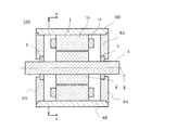
- FIG. 2 is a cross-sectional view illustrating an entire configuration of the rotating electric machine according to Embodiment 1 of the present invention.
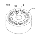
- FIG. 2 is a perspective view showing a configuration of the rotating electric machine according to Embodiment 1 of the present invention. It is AA sectional drawing of FIG.
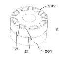
- FIG. 2 is a perspective view showing a configuration of a rotor of the rotary electric machine according to Embodiment 1 of the present invention.
- FIG. 2 is an exploded perspective view showing a configuration of one pole of a rotor of the rotary electric machine according to Embodiment 1 of the present invention.
- FIG. 6 is a partial cross-sectional view of the first rotor unit shown in FIG. FIG.
- FIG. 6 is a partial sectional view of a second rotor unit shown in FIG. 5.
- FIG. 5 is a diagram showing a graph of an analysis result of verifying torque pulsation in the rotating electric machine according to Embodiment 1 of the present invention.
- FIG. 13 is a partial cross-sectional view of a first rotor unit of the rotary electric machine according to Embodiment 2 of the present invention.
- FIG. 13 is a partial cross-sectional view of a second rotor unit of the rotary electric machine according to Embodiment 2 of the present invention.
- FIG. 11 is a diagram illustrating a flow of a magnetic flux from a stator in a first rotor unit of a rotary electric machine according to Embodiment 2 of the present invention.
- FIG. 11 is a diagram illustrating a flow of a magnetic flux from a stator in a first rotor unit of a rotary electric machine according to Embodiment 2 of the present invention.
- FIG. 13 is a diagram illustrating a flow of a magnetic flux from a stator in a second rotor unit of the rotary electric machine according to Embodiment 2 of the present invention.
- FIG. 13 is a diagram illustrating a flow of a magnetic flux from a stator in a second rotor unit of the rotary electric machine according to Embodiment 2 of the present invention.
- FIG. 13 is a partial cross-sectional view of a first rotor unit of the rotary electric machine according to Embodiment 3 of the present invention.
- FIG. 13 is a partial cross-sectional view of a second rotor unit of the rotary electric machine according to Embodiment 3 of the present invention.
- FIG. 15 is an exploded perspective view showing a configuration of one pole of a rotor of a rotary electric machine according to Embodiment 4 of the present invention.
- FIG. 15 is an exploded perspective view showing a configuration of one pole of a rotor of a rotary electric machine according to Embodiment 5 of the present invention.
- FIG. 15 is a partial cross-sectional view of a first rotor unit of a rotary electric machine according to Embodiment 6 of the present invention.
- FIG. 15 is a partial cross-sectional view of a second rotor unit of the rotary electric machine according to Embodiment 6 of the present invention.
- FIG. 13 is a sectional view taken along the line AA of FIG. 1 showing a configuration of a rotating electric machine according to Embodiment 7 of the present invention.
- FIG. 15 is a partial cross-sectional view of a first rotor unit of a rotary electric machine according to Embodiment 7 of the present invention.
- FIG. 17 is a partial cross-sectional view of a second rotor unit of the rotary electric machine according to Embodiment 7 of the present invention.
- FIG. 15 is an exploded perspective view showing a configuration of one pole of a rotor of a rotary electric machine according to Embodiment 8 of the present invention.
- FIG. 15 is an exploded perspective view showing a configuration of one pole of a rotor of a rotary electric machine according to Embodiment 8 of the present invention.
- FIG. 1 is a cross-sectional view showing the entire configuration of the rotating electric machine according to Embodiment 1 of the present invention.
- FIG. 2 is a perspective view of the rotating electric machine shown in FIG. However, FIG. 2 does not show some components such as the housings 9A and 9B and the support shaft 4 in FIG.
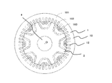
- FIG. 3 is a sectional view taken along line AA of FIG.
- the rotating electric machine 100 will be described by taking a three-phase permanent magnet type rotating electric machine of an 8-pole, 48-slot distributed winding type as an example.
- the rotating electric machine 100 includes an annular stator 1 and a columnar rotor 2 arranged inside the stator 1.
- a gap is provided between the inner peripheral surface of the stator 1 and the outer peripheral surface of the rotor 2.
- a shaft insertion hole 250 is provided in a central portion of the rotor 2.
- the support shaft insertion hole 250 is a through hole that passes through the rotor 2 in the axial direction.
- the support shaft 4 is inserted into the support shaft insertion hole 250.
- the support shaft 4 is fixed to the rotor 2.
- the stator 1 includes a stator core 10 and a stator coil 12.
- the stator core 10 is formed of an armature core.
- the stator 1 is fixed to the second housing 9B by fitting the outer peripheral surface of the stator core 10 and the inner peripheral surface of the second housing 9B.
- the first housing 9A and the second housing 9B constitute a housing as a housing of the rotating electric machine 100.
- the rotor 2 is rotatably supported by the support shaft 4 relative to the stator 1.
- the rotor 2 rotates about the support shaft 4.
- the axial centerline of the support shaft 4 is referred to as a rotation axis X.
- the stator core 10 includes an annular core back portion 101, 48 teeth 103 protruding from the core back portion 101 toward the rotor 2, and 48 slots 102 formed between the teeth 103. It is configured.
- the teeth 103 are arranged along the inner circumference of the stator core 10 at intervals in the circumferential direction.
- the teeth 103 are arranged, for example, at equal intervals.
- the stator core 10 is formed by stacking a plurality of stator core sheets of the same shape in the axial direction for the purpose of reducing eddy current.
- the stator core sheet is formed by punching out the same shape from an electromagnetic steel sheet.
- the tip of each tooth 103 of the stator core 10 faces the outer peripheral surface of the rotor 2 via a gap.
- the stator coil 12 is composed of 48 windings. Forty-eight windings are contained in slot 102. Each winding is wound around the stator core 10 in a distributed winding manner.
- the distributed winding method is a method in which a winding is wound over a plurality of teeth 103.
- the stator coil 12 is composed of 16 windings per phase. Therefore, the stator coil 12 is composed of a total of 48 windings for three phases. Forty-eight windings are connected. Each winding is connected to an inverter, which is a power converter (not shown). When a three-phase AC current is supplied from the inverter to the stator coil 12, a rotating magnetic field is generated from the stator 1 to the air gap, thereby generating torque in the rotor 2.
- FIG. 4 is an overall view of the rotor 2 according to the first embodiment.
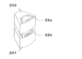
- the rotor 2 includes a first rotor unit 201 and a second rotor unit 202.
- the second rotor unit 202 is stacked on the first rotor unit 201.
- the outer dimensions of the first rotor unit 201 and the second rotor unit 202 are the same.
- the rotor 2 has eight pairs of permanent magnets 21 as described later. Each of the eight pairs of permanent magnets forms a magnetic pole. Therefore, the rotor 2 has eight magnetic poles. The central angles of the eight magnetic poles of the rotor 2 are equal. Therefore, in the first embodiment, the central angles of the eight magnetic poles are each 45 degrees.
- FIG. 5 is an exploded perspective view showing one magnetic pole portion of eight magnetic poles of rotor 2 according to the first embodiment. As shown in FIG. 5, the first rotor unit 201 and the second rotor unit 202 that constitute one magnetic pole have basically the same configuration, but differ in the configuration of slits 22a and 22b described later. I have. In the following description, corresponding components in the first rotor unit 201 and the second rotor unit 202, such as “22a” and “22b”, are represented by the same numerals followed by lowercase alphabets. .
- FIG. 6 is a view showing a cross-sectional shape of the first rotor unit 201 shown in FIG. Therefore, FIG. 6 shows one magnetic pole portion of the eight magnetic poles of the rotor 2.
- FIG. 6 shows a cross section along a plane perpendicular to the axial direction of the first rotor unit 201. Since the eight magnetic poles of the rotor 2 have the same configuration, only the configuration of one magnetic pole portion will be described below.
- the first rotor unit 201 includes, for each magnetic pole, a pair of permanent magnets 21a, a slit 22a formed between the pair of permanent magnets 21a, and a pair of flux barriers 23a. It is configured.
- the pair of permanent magnets 21a are inserted and fixed in the magnet insertion holes 24a.
- the center line of the magnetic pole formed by the pair of permanent magnets 21a is referred to as a d-axis 60.
- the pair of permanent magnets 21a are arranged in a V-shape so as to be line-symmetric with respect to the d-axis 60. Specifically, the distance between the pair of permanent magnets 21a gradually increases from the center of the rotor 2 toward the outer periphery. However, the pair of permanent magnets 21a are separated from each other and are not in contact with each other. Further, three rows of slits 22a extending in the circumferential direction are formed between the pair of permanent magnets 21a.
- Each slit 22a is a slit having an arcuate shape curved inward.
- the opening of the arc-shaped slit 22 a faces the inner peripheral surface of the stator 1.
- the three rows of slits 22a are arranged concentrically.
- Each slit 22a is formed so as to be symmetrical with respect to the d axis 60.
- Each slit 22a has a protruding inner diameter side. That is, each of the slits 22a is arranged such that both ends of the arc shape are arranged on the outer peripheral side of the rotor 2, and the center portion of the arc shape is closer to the center of the rotor 2 than both ends.
- the circumferential length of the slit 22a provided on the outermost peripheral side of the rotor 2 is the shortest, and the circumferential length of the slit 22a provided on the most central side of the rotor 2 is small.
- the length in the direction is the longest.
- the widths of the three rows of slits 22a are the same.
- a pair of flux barriers 23 a is provided on the outer peripheral portion of the rotor 2.
- Each flux barrier 23a is formed so as to be connected to the magnet insertion hole 24a of the permanent magnet 21a.
- the intersection of the cross section of the rotor 2 and the rotation axis X shown in FIG. 3 is referred to as the rotation axis center O.
- the center O of the rotation axis is not shown in FIG. 6, the angle between two straight lines connecting the outermost positions of both ends of the slit 22a and the center O of the rotation axis is defined as "arc angle”.
- the slits 22a are arranged such that the arc angles of the three rows of slits 22a are the arc angles ⁇ 1, ⁇ 2, and ⁇ 3, respectively.
- an angle between a straight line connecting the innermost positions of both ends on the outer peripheral side of the flux barrier 23a and the rotation axis center O is defined as "an angle formed by a pair of flux barriers”.
- the pair of flux barriers 23a is formed such that the angle formed by the pair of flux barriers 23a becomes ⁇ m.
- FIG. 7 is a diagram showing a cross-sectional shape of the second rotor unit 202 shown in FIG. Accordingly, FIG. 7 shows one magnetic pole portion of the eight magnetic poles of the rotor 2. FIG. 7 shows a cross section along a plane perpendicular to the axial direction of the second rotor unit 202. As shown in FIG. 7, the second rotor unit 202 includes, for each magnetic pole, a pair of permanent magnets 21b, a slit 22b formed between the pair of permanent magnets 21b, and a flux barrier 23b. ing.
- the pair of permanent magnets 21b are inserted and fixed in the magnet insertion holes 24b.
- the center line of the magnetic pole formed by the pair of permanent magnets 21b is referred to as a d-axis 60.
- the pair of permanent magnets 21b are arranged in a V-shape so as to be line-symmetric with respect to the d-axis 60. Specifically, the distance between the pair of permanent magnets 21b gradually increases from the center of the rotor 2 toward the outer periphery. However, the pair of permanent magnets 21b are separated from each other and are not in contact with each other. Two rows of slits 22b are formed between the pair of permanent magnets 21b.
- Each slit 22b is a slit having an inwardly curved arc shape.
- the opening of the lone-shaped slit 22 b faces the inner peripheral surface of the stator 1.
- the two rows of slits 22b are arranged concentrically.
- Each slit 22b is formed so as to have a line-symmetrical shape about the d-axis 60.
- each slit 22b has a protruding inner diameter side. That is, the slits 22b are arranged such that both ends of the arc shape are on the outer peripheral side of the rotor 2 and the center portion of the arc shape is closer to the center of the rotor 2 than both ends.
- the slits 22b are arranged such that both ends of the arc shape are located on the outer peripheral side of the rotor 2 and the center portion of the arc shape is located closer to the center than both ends. Also, of the two rows of slits 22b, the circumferential length of the slit 22b provided on the outermost periphery of the rotor 2 is the shortest, and the circumferential length of the slit 22b provided on the most central side of the rotor 2 is smaller. The length in the direction is the longest. However, the widths of the two rows of slits 22b are the same. Further, a pair of flux barriers 23b is provided on the outer peripheral portion of the rotor 2. Each flux barrier 23b is formed so as to be connected to the magnet insertion hole 24b of the permanent magnet 21b.
- the center of the rotation axis through which the rotation axis X of the rotor 2 passes is referred to as the rotation axis center O.
- the center O of the rotation axis is not shown, but the angle between straight lines connecting the outermost positions of both ends of the slit 22b and the center O of the rotation axis is defined as "arc angle”.
- the slits 22b are arranged such that the arc angles of the two rows of slits 22b are the arc angles ⁇ ′1 and ⁇ ′2, respectively.
- a pair of flux barriers 23b is formed so that the angle between the innermost position of both ends of the flux barrier 23b on the outer peripheral side of the rotor 2 and a straight line connecting the rotation axis center O is ⁇ m. I have.
- the arc angles ⁇ 1, ⁇ 2, ⁇ 3, ⁇ ′1, and ⁇ ′2 are defined as the distances between the straight lines connecting the outermost positions of both ends of the slits 22a and 22b and the rotation axis center O.
- the angle is not limited to this, and may be an angle between straight lines connecting the innermost positions of both ends of the slits 22a and 22b and the rotation axis center O.
- the angle ⁇ m is defined as an angle between a straight line connecting the innermost positions of both ends of the flux barriers 23a and 23b and the rotation axis center O.
- both ends of the flux barriers 23a and 23b are May be an angle between a straight line connecting the outermost position of and the rotation axis center O.
- the angle ⁇ m is defined using the positions of both ends of the flux barriers 23a and 23b.
- the present invention is not limited to this, and the angle ⁇ m is defined using the positions of both ends of the permanent magnets 21a and 21b. You may make it.
- the arc angles and the number of rows of the slits 22a and the slits 22b are different between the first rotor unit 201 and the second rotor unit 202 adjacent in the axial direction.
- the magnetic path of the first rotor unit 201 through which the magnet magnetic flux passes is different from the magnetic path of the second rotor unit 202 through which the magnet magnetic flux passes. Therefore, in the first embodiment, the magnetic fluxes of the permanent magnets 21a and 21b are different between the rotor units 201 and 202.
- the first rotor unit 201 and the second rotor unit 202 show the case where both the arc angle and the number of rows are different between the slit 22a and the slit 22b, but the present invention is not limited to this case. , And at least one of the arc angle and the number of columns may be different.
- the shapes and positions of the magnet insertion hole 24a for inserting the pair of permanent magnets 21a and the magnet insertion hole 24b for inserting the pair of permanent magnets 21b are the same in the first rotor unit 201 and the second rotor unit 202. Also, the shapes of the pair of permanent magnets 21a and 21b are the same in the first rotor unit 201 and the second rotor unit 202.
- the electromagnetic force F is proportional to the square of the air gap magnetic flux density B as shown in the following equation (1), and the magnetic flux density can be expressed as a function of the spatial harmonic order k and the time harmonic order ⁇ .
- ⁇ is a circumferential position
- t is time
- ⁇ is an angular frequency
- a (k, ⁇ ) represents the amplitude for the harmonic spatial order and the harmonic time order
- ⁇ (k, ⁇ ) represents the phase for the harmonic spatial order and the harmonic time order.
- the air gap magnetic flux density B is calculated based on the result of multiplication of the permeance of the rotor 2 and the magnetomotive force of the permanent magnets 21a and 21b.
- Permeance is a measure of the magnetoresistance.
- the amplitude and phase of the permeance harmonic component of the rotor 2 change according to the arc angles and the number of the slits 22a and 22b and the flux barriers 23a and 23b.
- the amplitude A (k, ⁇ ) of the air gap magnetic flux density and the phase ⁇ (k, ⁇ ) change.
- the torque ripple is one form of the electromagnetic force F that can be expressed by the spatial order 0 order and the time order ⁇ order. Therefore, it can be said that the amplitude and the phase are changed by being affected by the arc angles and the numbers of the slits 22a and 22b and the flux barriers 23a and 23b.
- the multiplication result of the magnetomotive force and the permeance has a large effect on the air gap magnetic flux density B. Therefore, the amplitude and phase of the torque ripple can be changed by changing the shapes of the slits 22a and 22b and the flux barriers 23a and 23b so that the magnetic path through which the magnet magnetic flux passes differs. Further, by forming the slits 22a and 22b as arc-shaped slits, it is possible to form a d-axis in which magnetic flux does not easily flow and a q-axis perpendicular to the d-axis in which magnetic flux easily flows. As a result, it plays a role in increasing reluctance torque.
- FIG. 8 shows a change in torque of the rotating electric machine 100 according to Embodiment 1 analyzed by the finite element method.
- the horizontal axis shows the electrical angle
- the vertical axis shows the torque.
- a solid line 80 indicates a torque pulsation generated in the first rotor unit 201
- a broken line 81 indicates a torque pulsation generated in the second rotor unit 202
- a dashed line 82 indicates the first rotor unit 201 and the second rotor unit.
- 4 shows torque pulsation generated in a rotor 2 combined with a rotor unit 202.
- the first rotor unit 201 and the second rotor unit 202 set the shaft length ratio so that the amplitude of the specific order of the torque pulsation is equal and the phases are reversed, so that the electrical angle of the entire rotor unit is increased.
- the torque ripple can be offset without reducing the average torque.
- the shaft length ratio is the ratio of the height of each rotor unit.
- the slit 22a and the slit 22b are described as arc-shaped slits.
- the slit 22a and the slit 22b may have a U-shape extending in the circumferential direction, and may have a shape formed by combining three or more straight lines, and may be formed by combining three or more curves. It may be shaped or consist of one arc.
- the rotor 2 has the two-stage rotor units stacked in the axial direction, that is, the first rotor unit 201 and the second rotor unit 202.
- Each of the first rotor unit 201 and the second rotor unit 202 includes a pair of permanent magnets 21a and 21b, and one or more rows of arc-shaped slits 22a and 22b provided between the pair of permanent magnets 21a and 21b, respectively. have.
- the output torque is not reduced, and the reduction of the output torque can be suppressed. Furthermore, in the first embodiment, since the magnet flux of the slit and the magnet flux of the flux barrier are taken into consideration, the reduction of the torque output due to the reduction of the magnet flux can be suppressed.
- FIG. 9 and 10 are cross-sectional views of first rotor unit 201 and second rotor unit 202 of the rotary electric machine according to Embodiment 2 of the present invention.
- 9 and 10 show one magnetic pole portion of the eight magnetic poles of the rotor 2 as in FIGS. 6 and 7 described above.
- FIG. 9 shows a cross section along a plane perpendicular to the axial direction of the first rotor unit 201.
- FIG. 10 shows a cross section along a plane perpendicular to the axial direction of the second rotor unit 202.
- the slits 22a of the first rotor unit 201 are three rows, and the slits 22b of the second rotor unit 202 are two rows.
- the slits 22c of the first rotor unit 201 are provided.
- the slits 22d of the second rotor unit 202 are each arranged in one row.
- the widths of the three rows of slits 22a and the two rows of slits 22b are all the same, but in the second embodiment, the width of the slit 22c is different from the width of the slit 22d. . Specifically, the width of the slit 22c is larger than the width of the slit 22d.
- the other configuration is the same as that of the first embodiment, and the description is omitted here.
- the first rotor unit 201 includes a pair of permanent magnets 21c, a slit 22c, and a pair of flux barriers 23c, as in the first embodiment.
- the second rotor unit 202 includes a pair of permanent magnets 21d, a slit 22d, and a pair of flux barriers 23d, as in the first embodiment. .
- the arc angle of the slit 22c of the first rotor unit 201 is ⁇ 1.
- the arc angle of the slit 22d of the second rotor unit 202 is ⁇ 2.
- the arc angle ⁇ 1 is larger than the arc angle ⁇ 2.
- the width of the slit 22c is larger than the width of the slit 22d.
- the ends of the slits 22c and 22d located on the outer periphery of the rotor 2 are referred to as "outer periphery ends".
- the edges of the outer peripheral ends of the slits 22 c and 22 d are arranged along the outer periphery of the rotor 2.
- the circumferential distance w1 indicating the width of the outer peripheral end of the slit 22c is larger than the circumferential distance w2 indicating the width of the outer peripheral end of the slit 22d.
- the width of the slit 22c is generally larger than the width of the slit 22d.
- the present invention is not limited to this, and at least the width of the outer peripheral end of the slit 22c may be larger than the width of the outer peripheral end of the slit 22d.
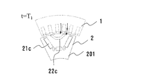
- the notation “ ⁇ ” described above the arrow indicates that the flow of the magnetic flux is blocked by the slit 22c.
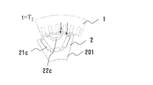
- the notation “ ⁇ ” described above the arrow indicates a state in which the flow of the magnetic flux is not completely blocked by the slit 22d.
- FIG. 11 and FIG. 12 showing the first rotor unit 201 will be compared.
- the magnetic flux from the stator 1 is greater in the slit 22c of the first rotor unit 201 than in the slit 22d of the second rotor unit 202. It can be seen that the flow of water is efficiently blocked. The reason is that the circumferential distance w1 of the outer peripheral end of the slit 22c is larger than the circumferential distance w2 of the outer peripheral end of the slit 22d. In other words, the slit efficiently blocks the flow of the magnetic flux from the stator 1 as the circumferential distance of the outer peripheral end increases.
- the timing at which the magnetic flux from the stator 1 is obstructed can be changed by changing the circumferential distance between the outer circumferential ends of the slits 22c and 22d. Therefore, in the second embodiment, the circumferential distances w1 and w2 of the outer circumferential ends of the slits 22c and 22d are set to different values. As described above, by appropriately setting the circumferential distances w1 and w2 of the outer circumferential ends of the slits 22c and 22d to appropriate values, the torque ripple generated for each of the first rotor unit 201 and the second rotor unit 202 is set. Can be appropriately adjusted.
- the circumferential distances w1 and w2 of the outer peripheral ends of the arc-shaped slits 22c and 22d are determined by the first rotor unit 201 and the second rotor unit 202 adjacent in the axial direction. Different from each other. Therefore, since the phases of the torque ripple generated for each rotor unit are different, the torque ripple can be canceled when viewed as the whole rotor 2. As a result, torque ripple can be reduced while suppressing a decrease in torque output.
- FIG. 15 and 16 are cross-sectional views of first and second rotor units 201 and 202 of the rotary electric machine according to Embodiment 3 of the present invention.
- FIGS. 15 and 16 show one magnetic pole portion of the eight magnetic poles of the rotor 2 as in FIGS. 6 and 7 described above.
- FIG. 15 shows a cross section along a plane perpendicular to the axial direction of the first rotor unit 201.
- FIG. 16 shows a cross section along a plane perpendicular to the axial direction of the second rotor unit 202.
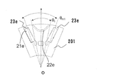
- the angle ⁇ m formed by the pair of flux barriers 23a of the first rotor unit 201 and the angle ⁇ m formed by the pair of flux barriers of the second rotor unit 202 are the same.
- the angle ⁇ m1 formed by the pair of flux barriers 23e of the first rotor unit 201 is different from the angle ⁇ m2 formed by the pair of flux barriers 23f of the second rotor unit 202.
- the slits 22a of the first rotor unit 201 are three rows, and the slits 22b of the second rotor unit 202 are two rows.
- the slits 22e and the slits 22f of the second rotor unit 202 are both arranged in one row.
- the width of the slit 22c of the first rotor unit 201 is different from the width of the slit 22d of the second rotor unit 202.
- the width of the slit 22e of the first rotor unit 201 and the width of the slit 22f of the second rotor unit 202 are the same.
- the first rotor unit 201 includes a pair of permanent magnets 21e, a slit 22e, and a pair of flux barriers 23e, as in the first embodiment.
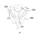
- the second rotor unit 202 includes a pair of permanent magnets 21f, a slit 22f, and a pair of flux barriers 23f.
- the angle ⁇ m1 formed by the pair of flux barriers 23e of the first rotor unit 201 and the angle ⁇ m2 formed by the pair of flux barriers 23f of the second rotor unit 202 are different.
- the arc angle ⁇ 1 of the slit 22e of the first rotor unit 201 is different from the arc angle ⁇ 2 of the slit 22f of the second rotor unit 202.
- the magnetic path of the magnetic flux passing through the outer peripheral side of the rotor 2 is different. Therefore, the manner in which the magnetic flux from the stator 1 flows differs between the first rotor unit 201 and the second rotor unit 202. As a result, pulsation of the generated torque ripple can be reduced.
- the angle ⁇ m1 formed by the pair of flux barriers 23e of the first rotor unit 201 and the angle ⁇ m2 formed by the pair of flux barriers 23f of the second rotor unit 202 are different.
- the arc angle ⁇ 1 of the slit 22e of the first rotor unit 201 is different from the arc angle ⁇ 2 of the slit 22f of the second rotor unit 202. Therefore, since the phases of the torque ripple generated for each rotor unit are different, the torque ripple can be canceled when viewed as the whole rotor 2. As a result, torque ripple can be reduced while suppressing a decrease in torque output.
- FIG. 17 is an exploded perspective view of rotor 2 according to Embodiment 4 of the present invention.
- FIG. 17 shows one magnetic pole portion of the eight magnetic poles of the rotor 2.
- rotor 2 is provided with a three-stage rotor unit. Other configurations are the same as in the first embodiment.
- the first-stage and third-stage rotor units counted from below have the same shape, and the first-stage and second-stage rotor units have the same shape. different.
- the first-stage and third-stage rotor units are configured by the second rotor unit 202 described in the first embodiment, and the second-stage rotor unit is replaced by the second embodiment.
- 1 comprises the first rotor unit 201.
- the rotor units of a plurality of stages are composed of two types, the first rotor unit 201 and the second rotor unit 202, and the first rotor unit 201 and the second rotor unit 202 are alternately stacked.
- the phase of the generated torque ripple changes according to the position of the rotating shaft of the rotor 2 in the axial direction. Specifically, the torque ripples have opposite phases at both ends of the rotation shaft of the rotor 2 and at the center. Therefore, by configuring the rotor 2 with a three-stage rotor unit and having a different configuration only in the second-stage rotor unit, the rotation axis X of the rotor 2 is oriented in a direction perpendicular to the rotation axis X. It is possible to change the mode of the vibration generated so as to bend. Therefore, by designing the rotor 2 using a three-stage rotor unit so as not to match the mode of the resonance frequency of the rotor 2, vibration and noise can be reduced.
- the rotor 2 is configured by a three-stage rotor unit. Further, the first rotor units 201 and the second rotor units 202 are alternately stacked. Accordingly, since the phases of the torque ripple generated for each rotor unit are different, the torque ripple can be offset when viewed as the entire rotor 2. Therefore, torque ripple can be reduced. In addition, since the electromagnetic force generated by each rotor unit is different, when viewed in the height direction of the rotation axis, the mode of the resonance frequency that deforms the rotation axis X can be changed, and vibration and noise can be reduced.
- the second-stage rotor unit is configured differently from the first-stage and third-stage rotor units.
- the present invention is not limited to this case, and the third-stage rotor unit may have a different configuration from the first-stage and second-stage rotor units.
- the configuration may be different from the rotor unit of the stage.
- three types of rotor units may be used, and the first-stage rotor unit, the second-stage rotor unit, and the third-stage rotor unit may all have different configurations.
- at least one of the arc angle of the slit and the number of rows of the slits may be different between at least two rotor units.
- FIG. 18 is an exploded perspective view of rotor 2 according to Embodiment 5 of the present invention.
- FIG. 18 shows one magnetic pole portion of the eight magnetic poles of the rotor 2.
- the rotor 2 is provided with a four-stage rotor unit. Other configurations are the same as in the first embodiment.
- the first-stage and third-stage rotor units counted from below have the same shape
- the second-stage and fourth-stage rotor units have the same shape.
- Shape the shapes of the first-stage and second-stage rotor units are different.
- the first-stage and third-stage rotor units are constituted by the second rotor unit 202 shown in the first embodiment
- the second-stage and fourth-stage rotor units are The first rotor unit 201 shown in the first embodiment is constituted.
- the rotor units of a plurality of stages are composed of two types, the first rotor unit 201 and the second rotor unit 202, and the first rotor unit 201 and the second rotor unit 202 are alternately stacked.
- the phase of the generated torque ripple changes according to the position of the rotating shaft of the rotor 2 in the axial direction.
- the torque ripples have opposite phases at both ends of the rotation shaft of the rotor 2 and at the center. Therefore, the rotor 2 is constituted by four-stage rotor units, and only the second-stage and fourth-stage rotor units are configured differently, so that the rotation axis of the rotor 2 is perpendicular to the rotation axis. It is possible to change the mode of the vibration generated so as to bend in an arbitrary direction. Therefore, by designing the rotor 2 using a four-stage rotor unit so as not to coincide with the mode of the resonance frequency of the rotor 2, vibration and noise can be reduced.
- the rotor 2 is configured by a four-stage rotor unit. Further, the first rotor units 201 and the second rotor units 202 are alternately stacked. Accordingly, since the phases of the torque ripple generated for each rotor unit are different, the torque ripple can be offset when viewed as the entire rotor 2. Therefore, torque ripple can be reduced. In addition, since the electromagnetic force generated by each rotor unit is different, when viewed in the height direction of the rotation axis, the mode of the resonance frequency that deforms the rotation axis X can be changed, and vibration and noise can be reduced.
- the first rotor units 201 and the second rotor units 202 are alternately stacked.
- the present invention is not limited to this case.
- the first rotor unit 201, the second rotor unit 202, the second rotor unit 202, and the first rotor unit 201 may be stacked in order from the bottom.
- three types of rotor units may be stacked in order from the bottom, such as a first rotor unit 201, a second rotor unit 202, a second rotor unit 202, and a third rotor unit.
- first rotor unit 201, the first rotor unit 201, the second rotor unit 202, and the third rotor unit may be stacked in order from the bottom.
- four types of rotor units may be used, and all of the first to fourth stage rotor units may have different configurations.
- the order of lamination may be any order.
- at least one of the arc angle of the slit and the number of rows of the slits may be different between at least two rotor units.
- FIG. 19 is a diagram showing a cross-sectional shape of first rotor unit 201 of rotor 2 according to Embodiment 6 of the present invention.
- FIG. 19 shows one magnetic pole portion of the eight magnetic poles of the rotor 2.
- FIG. 19 shows a cross section along a plane perpendicular to the axial direction of the first rotor unit 201.
- FIG. 20 shows a cross-sectional shape of second rotor unit 202 of rotor 2 according to Embodiment 6 of the present invention.
- FIG. 20 shows one magnetic pole portion of the eight magnetic poles of the rotor 2.
- FIG. 20 shows a cross section along a plane perpendicular to the axial direction of the second rotor unit 202.
- the slit 22e of the first rotor unit 201 and the slit 22f of the second rotor unit 202 are both line-symmetrical with respect to the d-axis 60.
- the slit 22g of the first rotor unit 201 and the slit 22h of the second rotor unit 202 are not both line-symmetric with respect to the d-axis 60.
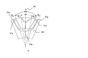
- the angle ⁇ m1 formed by the pair of flux barriers 23e of the first rotor unit 201 and the angle ⁇ m2 formed by the pair of flux barriers 23f of the second rotor unit 202 are different, and The arc angle ⁇ 1 of the slit 22e of the first rotor unit 201 and the arc angle ⁇ 2 of the slit 22f of the second rotor unit 202 were different.
- the angle ⁇ m formed by the pair of flux barriers 23g of the first rotor unit 201 and the angle ⁇ m formed by the pair of flux barriers 23h of the second rotor unit 202 are the same, and
- the arc angle ⁇ 1 of the slit 22g of the first rotor unit 201 and the arc angle ⁇ 2 of the slit 22h of the second rotor unit 202 are the same.
- the first rotor unit 201 includes a pair of permanent magnets 21g, a slit 22g, and a pair of flux barriers 23e, as in the first embodiment.
- the second rotor unit 202 includes a pair of permanent magnets 21h, a slit 22h, and a pair of flux barriers 23h.
- the slit 22g of the first rotor unit 201 is not line-symmetric with respect to the d-axis 60. Therefore, in the following description, as shown in FIG. 19, the arc angle of the slit 22g is divided into two with the d axis as the boundary line, and the arc angle on the leading side in the rotation direction is called ⁇ 11, Is called ⁇ 12. Therefore, the arc angle of the slit 22g is ⁇ 11 + ⁇ 12. At this time, the arc angle ⁇ 11 on the rotation direction leading side and the arc angle ⁇ 12 on the rotating direction return side are different.
- the slit 22h of the second rotor unit 202 is not line-symmetric with respect to the d-axis 60. Therefore, in the following description, as shown in FIG. 20, the arc angle of the slit 22h is divided into two with the d axis as a boundary line, and the arc angle on the leading side in the rotation direction is called ⁇ 21, and Is referred to as ⁇ 22. Therefore, the arc angle of the slit 22h is ⁇ 21 + ⁇ 22. At this time, the arc angle ⁇ 21 on the leading side in the rotating direction is different from the arc angle ⁇ 22 on the returning side in the rotating direction.
- the first rotor unit 201 and the second rotor unit 202 generate the first rotor unit 201 by setting the arc angle of the slit 22g and the arc angle of the slit 22h to different angles.
- the phase of the torque ripple and the phase of the torque ripple generated in the second rotor unit 202 can be changed.
- the arc angle on the rotation direction advance side and the arc angle on the rotation direction return side are set to different angles.
- the current lead angle at which the reluctance torque reaches a peak value can be shifted.
- the current advance at which the reluctance torque has a peak value can be made closer to the current advance at which the magnet torque has a peak value.
- the maximum torque can be improved.
- the rotation direction is The arc angle ⁇ 21 on the advance side and the arc angle ⁇ 22 on the return side in the rotation direction are different.
- the arc angle ⁇ 11 of the first rotor unit 201 on the rotation direction advance side is different from the arc angle ⁇ 21 of the second rotor unit 202 on the rotation direction advance side, and the arc angle ⁇ 12 on the rotation direction return side of the first rotor unit 201 is different.
- the arc angle ⁇ 22 on the rotation direction return side of the second rotor unit is different.
- the phases of the torque ripple generated for each rotor unit are different, the torque ripple can be offset when the entire rotor 2 is viewed.
- the arc angle of the slit between the rotation direction leading side and the rotation direction return side the phase of the magnet magnetic flux is unevenly distributed on the rotation direction leading side, and the phase of the reluctance magnetic flux is unevenly distributed on the rotation direction return side. it can.
- the current advance at which the magnet torque peaks and the current advance at which the reluctance torque peaks can be brought closer to each other, and the output torque can be increased.
- FIG. FIG. 21 is a plan view showing a configuration of a rotating electric machine according to Embodiment 7 of the present invention.
- the rotating electric machine 100A according to the seventh embodiment includes a stator 41 and a rotor.
- a description will be given by taking a three-phase permanent magnet type rotating electric machine of a concentrated winding type having 12 poles and 18 slots as an example of rotating electric machine 100A.
- the entire configuration of the rotating electric machine 100A according to the seventh embodiment is basically the same as that of FIG. 1, and thus the description thereof is omitted here.
- stator 41 and rotor 42 of rotating electric machine 100A is different from stator 1 and rotor 2 described in the first embodiment, although the number of poles and the number of slots are different. Therefore, the description is omitted here.
- the stator coil 12 is wound around each of the teeth 103 provided on the stator core 10 in a distributed winding manner, but in the seventh embodiment, the stator coil 12 is wound. Are wound around the teeth 103 provided on the stator core 10 in a concentrated winding manner.
- the rotor 42 is configured by stacking two stages of rotor units in the axial direction, as in the first embodiment.
- the first-stage rotor unit is referred to as a first rotor unit 203
- the second-stage rotor unit is referred to as a second rotor unit 204.
- FIG. 22 is a diagram showing a cross-sectional shape of the first rotor unit 203 of the rotor 42 according to Embodiment 7 of the present invention.
- FIG. 22 shows one magnetic pole portion of the twelve magnetic poles of the rotor 42.
- FIG. 22 shows a cross section along a plane perpendicular to the axial direction of the first rotor unit 203.
- FIG. 23 is a diagram showing a cross-sectional shape of the second rotor unit 204 of the rotor 42 according to Embodiment 7 of the present invention.
- FIG. 23 shows one magnetic pole portion of the twelve magnetic poles of the rotor 42.
- FIG. 23 shows a cross section along a plane perpendicular to the axial direction of the second rotor unit 204.
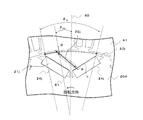
- the first rotor unit 203 includes a pair of permanent magnets 21i, a slit 22i provided between the pair of permanent magnets 21i, and a pair of flux barriers 23i.
- the pair of permanent magnets 21i are inserted and fixed in the magnet insertion holes 24i.
- the pair of permanent magnets 21i are arranged in a V-shape so as to be line-symmetric with respect to the d-axis 60.
- the slit 22i has a band shape.
- one point of the pair of permanent magnets 21i on the side of the permanent magnet 21i arranged on the rotation direction return side is defined as a point P.
- An air gap is provided between the point P and the permanent magnet 21i.
- the point P is disposed along one of the two sides in the longitudinal direction of the permanent magnet 21i that is closer to the outer peripheral side.
- a point shifted from the point P toward the rotation direction advance side and one point on the outer peripheral side of the rotor 2 is defined as a point Q.
- the slit 22i is formed along a straight line connecting the points P and Q.
- the distance in the longitudinal direction of the slit 22i is the same as the linear distance between the point P and the point Q.
- the angle formed between the straight line 61 connecting the point Q and the center O of the rotation axis and the d-axis 60 is called the deflection angle of the strip-shaped slit 22i, and is defined as the deflection angle ⁇ 31. It is desirable that the point P is located on the rotation direction return side of the d-axis 60 and the point Q is located on the rotation direction advance side of the d-axis 60. Further, as shown in FIG.
- the distance from the intersection of one side of the permanent magnet 21i on the side where the point P is disposed and the straight line connecting the point Q and the point P to the end of the permanent magnet 21i is represented by a distance L.
- the distance L is appropriately set to an arbitrary value.
- the phase of the magnet magnetic flux is unevenly distributed to the rotational direction leading side, Further, the phase of the reluctance magnetic flux can be unevenly distributed on the return side in the rotation direction.
- the current advance angle at which the magnet torque peaks and the current advance angle at which the reluctance torque peaks can be brought closer to each other, and as a result, the torque can be increased.
- the second rotor unit 204 includes a pair of permanent magnets 21j, a slit 22j provided between the pair of permanent magnets 21j, and a pair of flux barriers 23j. .
- the pair of permanent magnets 21j are inserted and fixed in the magnet insertion holes 24j.
- the pair of permanent magnets 21j are arranged in a V-shape so as to be line-symmetric with respect to the d-axis 60.
- the slit 22j has a band shape.
- one point of the pair of permanent magnets 21j on the side of the permanent magnet 21j arranged on the return side in the rotation direction is defined as a point P.
- An air gap is provided between the point P and the permanent magnet 21j.
- the point P is disposed along one of the two sides in the longitudinal direction of the permanent magnet 21i that is closer to the outer peripheral side.
- one point on the outer side of the rotor 2 on the leading side in the rotation direction from the point P is defined as a point Q.
- the slit 22j is formed along a straight line connecting the points P and Q.
- the distance in the longitudinal direction of the slit 22j is the same as the distance between the point P and the point Q.
- the angle formed by the straight line 61 connecting the point Q and the rotation axis center O and the d-axis 60 is called the deflection angle of the strip-shaped slit 22j, and is defined as the deflection angle ⁇ 32. It is desirable that the point P is located on the rotation direction return side of the d-axis 60 and the point Q is located on the rotation direction advance side of the d-axis 60. Further, as shown in FIG.
- the distance from the intersection of one side of the permanent magnet 21i on the side where the point P is disposed and the straight line connecting the point Q and the point P to the end of the permanent magnet 21i is represented by a distance L.
- the distance L is appropriately set to an arbitrary value.
- the deflection angle ⁇ 31 in FIG. 22 and the deflection angle ⁇ 32 in FIG. 23 are ⁇ 31 ⁇ ⁇ 32.
- the phase of the magnet magnetic flux is unevenly distributed toward the rotation direction advance side, Further, the phase of the reluctance magnetic flux can be unevenly distributed on the return side in the rotation direction.
- the current advance angle at which the magnet torque peaks and the current advance angle at which the reluctance torque peaks can be brought closer to each other, and as a result, the torque can be increased.
- the deflection angle ⁇ 31 in FIG. 22 and the deflection angle ⁇ 32 in FIG. 23 are ⁇ 31 ⁇ ⁇ 32.
- the magnetic path of the magnet magnetic flux changes.
- the amplitude and phase of the permeance harmonic of the rotor 42 change. Therefore, the phase of the torque ripple generated in the first rotor unit 203 and the phase of the torque ripple generated in the second rotor unit 204 can be changed. As a result, the torque ripple can be offset by the rotor 42 as a whole.
- the seventh embodiment by tilting the outer peripheral end of the slits 22i and 22j toward the rotation direction, the phase of the magnet flux is unevenly distributed toward the rotation direction advance side, and the phase of the reluctance flux is changed. It can be unevenly distributed on the return side in the rotation direction. Therefore, at the time of the power running operation, the current advance angle at which the magnet torque peaks and the current advance angle at which the reluctance torque peaks can be brought close to each other, and the output torque can be increased.
- the deflection angle ⁇ 31 of the slit 22i in the first rotor unit 203 and the deflection angle ⁇ 32 of the slit 22j in the second rotor unit 204 are set to different angles, the magnetic path of the magnet flux changes, and the permeance harmonic of the rotor 42 changes. The amplitude and phase of the wave change. Therefore, since the phase of the torque ripple generated in the first rotor unit 203 and the phase of the torque ripple generated in the second rotor unit 204 can be changed, the torque ripple can be offset as the whole rotor 42. Can be done. As a result, torque ripple can be reduced.
- the number of columns of the slits 22i and 22j is 1.
- the present invention is not limited to this, and the number of columns of the slits 22i and 22j may be any value of 2 or more.
- the number of stages of the rotor unit has been described as being two, any number of stages may be used.
- the rotor 42 is configured such that at least one of the deflection angles of the strip-shaped slits 22i and 22j and the number of rows of the slits 22i and 22j is different between rotor units adjacent in the axial direction.
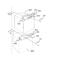
- FIG. 24 is an exploded perspective view showing one pole of a rotor showing a configuration of a rotary electric machine according to Embodiment 8 of the present invention.
- the rotor includes a first rotor unit 401 and a second rotor unit 402.
- the first rotor unit 401 has three rows of magnetic slits 43a
- the second rotor unit 402 has two rows of magnetic slits 43b, each having a different cross-sectional shape.
- the magnetic slit 43a in the first rotor unit 401 has a symmetry axis 63 for each pole.
- the magnetic slit 43b in the second rotor unit 402 has a symmetry axis 64 for each pole.
- a pair of magnets 44a, a pair of magnet insertion holes 45a, a flux barrier 46a, A slit 43a is arranged.
- a pair of magnets 44b, a pair of magnet insertion holes 45b, and a flux barrier 46b are formed so as to be line-symmetric with respect to the symmetry axis 64. And a magnetic slit 43b.
- the axis of symmetry 63 of the first rotor unit 401 is counterclockwise with respect to the axis of symmetry 64 of the second rotor unit 402 by an angle ⁇ [deg] around the rotation axis of the rotor.
- the first rotor unit 401 is shifted and disposed with respect to the second rotor unit 402 such that the first rotor unit 401 is rotated to the position rotated around.
- the first rotor unit 401 and the second rotor unit 402 are rotated and shifted to form a skewed rotor unit, and the spatial phase of the magnetomotive force itself of the magnet is changed by the first rotor unit 401 and the second rotor unit. It can be shifted between the unit 402. As a result, the phase of the torque ripple generated in each of the first rotor unit 401 and the second rotor unit 402 can be shifted, so that the torque ripple can be reduced as a whole rotor.
- the configuration shown in FIG. 25 may be used. That is, as shown in FIG. 25, when viewed from the height direction of the rotating shaft, the position of the magnet 47a of the first rotor unit 403 and the position of the magnet 47b of the second rotor unit 404 may be the same. .
- the symmetry axis of the magnetic slit 48a of the first rotor unit 403 is defined as the symmetry axis 65
- the symmetry axis of the magnetic slit 48b of the second rotor unit 404 is defined as the symmetry axis 66.
- the symmetry axis 65 is disposed at a position rotated counterclockwise by an angle ⁇ [deg] around the rotation axis of the rotor with respect to the symmetry axis 66. That is, in FIG. 25, when viewed from the height direction of the rotation axis, the symmetry axis 65 is not at the same position as the symmetry axis 66 but at a shifted position.
- the magnets 47a , 47b can be inserted through the first rotor unit 403 and the second rotor unit 404 from the height direction of the rotation shaft.
- the leakage magnetic flux between the first rotor unit 403 and the second rotor unit 404 due to the magnets 47a and 47b can be reduced.
- the axis of symmetry 65 of the magnetic slit 48a of the first rotor unit 403 and the axis of symmetry 66 of the magnetic slit 48b of the second rotor unit 404 are shifted by an angle ⁇ [deg], so that the center of the pole is shifted.
- non-magnetic regions can be localized. Accordingly, the magnet magnetic flux can be shifted between the leading side and the returning side in the rotation direction, so that the phases of the magnet magnetic fluxes of the first rotor unit 403 and the second rotor unit 404 can be shifted. As a result, it is possible to reduce the torque ripple caused by the magnet magnetic flux.
- the number of rotor units may be three or more.
- the axis of symmetry of the magnetic slit of at least one of the rotor units of the plurality of rotor units is set in a rotational direction about the axis of rotation with respect to the axis of symmetry of the magnetic slits of the other rotor units.
- the rotor units may be arranged so as to be shifted by a preset angle ⁇ [deg].
- angle ⁇ [deg] is not particularly limited, and may be appropriately set to an arbitrary angle.
- the slit 22 may be filled with a resin, a heat radiating material, or the like having a transmittance lower than the transmittance of the material constituting the first rotor unit 201 and the second rotor unit 202.
- stator core 12 stator coil
Landscapes
- Engineering & Computer Science (AREA)
- Power Engineering (AREA)
- Permanent Field Magnets Of Synchronous Machinery (AREA)
- Iron Core Of Rotating Electric Machines (AREA)
Abstract
Description
を備え、前記回転子は、軸方向に積層された複数段のロータユニットを有し、前記複数段のロータユニットのそれぞれは、一対の永久磁石と、前記一対の永久磁石間に径方向に1列以上配列されたスリットとを有し、前記スリットは、内径方向に突状の周方向に延びた弧状形状を有し、前記弧状形状の両端の位置と前記回転子の回転軸中心とを結んだ2つの直線が成す角度を、前記スリットの弧角としたとき、前記スリットの弧角および前記スリットの列数の少なくともいずれか一方が、少なくとも2つのロータユニット間で異なる。
図1は、本発明の実施の形態1に係る回転電機の全体の構成を示した断面図である。図2は、図1に示した回転電機の斜視図である。但し、図2においては、図1のハウジング9Aおよび9B、支軸4などのいくつかの構成要素については図示を省略している。図3は、図1のA-A断面図である。

図9および図10は、本発明の実施の形態2に係る回転電機の第1ロータユニット201および第2ロータユニット202の断面図である。図9および図10は、上記の図6および図7と同様に、回転子2の8個の磁極のうちの1つの磁極部分を示している。なお、図9は、第1ロータユニット201の軸方向に対して垂直な平面に沿った断面を示している。また、図10は、第2ロータユニット202の軸方向に対して垂直な平面に沿った断面を示している。
図15および図16は、本発明の実施の形態3に係る回転電機の第1ロータユニット201および第2ロータユニット202の断面図である。図15および図16は、上記の図6および図7と同様に、回転子2の8個の磁極のうちの1つの磁極部分を示している。なお、図15は、第1ロータユニット201の軸方向に対して垂直な平面に沿った断面を示している。また、図16は、第2ロータユニット202の軸方向に対して垂直な平面に沿った断面を示している。
図17は、本発明の実施の形態4に係る回転子2の分解斜視図である。図17は、回転子2の8個の磁極のうちの1つの磁極部分を示している。図17に示すように、本実施の形態4においては、回転子2は、3段のロータユニットを備えて構成されている。他の構成については、実施の形態1と同じである。
図18は、本発明の実施の形態5に係る回転子2の分解斜視図である。図18は、回転子2の8個の磁極のうちの1つの磁極部分を示している。図18に示すように、本実施の形態4においては、回転子2は、4段のロータユニットを備えて構成されている。他の構成については、実施の形態1と同じである。
図19は、本発明の実施の形態6に係る回転子2の第1ロータユニット201の断面形状を示す図である。図19は、回転子2の8個の磁極のうちの1つの磁極部分を示している。なお、図19は、第1ロータユニット201の軸方向に対して垂直な平面に沿った断面を示している。
図21は、本発明の実施の形態7に係る回転電機の構成を示した平面図である。本実施の形態7に係る回転電機100Aは、固定子41と回転子42とを備える。本実施の形態7においては、回転電機100Aとして、12極18スロットの集中巻き方式の3相の永久磁石式回転電機を例に挙げて説明する。
図24は、本発明の実施の形態8に係る回転電機の構成を示した回転子の1極分を示した分解斜視図である。回転子は、第1ロータユニット401と、第2ロータユニット402とで構成されている。第1ロータユニット401は、3列の磁気スリット43aを有し、第2ロータユニット402は2列の磁気スリット43bを有し、それぞれ異なる断面形状となっている。第1ロータユニット401における磁気スリット43aは、極毎に、対称軸63を有している。また、第2ロータユニット402における磁気スリット43bは、極毎に、対称軸64を有している。
Claims (9)
- 環状の固定子と、
前記固定子の内側に設けられた回転子と
を備え、
前記回転子は、軸方向に積層された複数段のロータユニットを有し、
前記複数段のロータユニットのそれぞれは、一対の永久磁石と、前記一対の永久磁石間に径方向に1列以上配列されたスリットとを有し、
前記スリットは、内径方向に突状の周方向に延びた弧状形状を有し、
前記弧状形状の両端の位置と前記回転子の回転軸中心とを結んだ2つの直線が成す角度を、前記スリットの弧角としたとき、
前記スリットの弧角および前記スリットの列数の少なくともいずれか一方が、少なくとも2つのロータユニット間で異なる、
回転電機。 - 前記スリットの少なくとも両端の幅は、少なくとも2つのロータユニット間で異なる、
請求項1に記載の回転電機。 - 前記複数段のロータユニットのそれぞれは、
前記一対の永久磁石が挿入される一対の磁石挿入孔と、
前記一対の磁石挿入孔に連結して設けられた一対のフラックスバリアと
をさらに有し、
前記一対のフラックスバリアの外周側端部と前記回転軸中心とをそれぞれ結んだ2つの直線が成す角度を、前記一対のフラックスバリアが成す角度としたとき、
前記一対のフラックスバリアが成す角度は、少なくとも2つのロータユニット間で異なる、
請求項1または2に記載の回転電機。 - 前記複数段のロータユニットのうち、少なくとも1つのロータユニットの前記磁気スリットの対称軸が、他のロータユニットの前記磁気スリットの対称軸に対して、前記回転軸を軸中心とする回転方向にシフトされて配置されている、
請求項1から3までのいずれか1項に記載の回転電機。 - 前記一対の磁石挿入孔の形状および位置は、前記複数段のロータユニット間で互いに同一である、
請求項1から4までのいずれか1項に記載の回転電機。 - 前記複数段のロータユニットの段数は、3以上である、
請求項1から5までのいずれか1項に記載の回転電機。 - 前記複数段のロータユニットは、第1ロータユニットと第2ロータユニットの2種類から構成され、
前記第1ロータユニットと前記第2ロータユニットとは交互に積層されている、
請求項1から6までのいずれか1項に記載の回転電機。 - 前記スリットの前記弧角を、前記一対の永久磁石が形成する磁極の中心線から2つに分けて、一方を回転方向進み側の弧角とし、他方を回転方向戻り側の弧角としたとき、
前記複数段のロータユニットのそれぞれにおいて、前記回転方向進み側の弧角と前記回転方向戻り側の弧角とは互いに異なり、
前記回転方向進み側の弧角は、少なくとも2つのロータユニット間で異なり、
前記回転方向戻り側の弧角は、少なくとも2つのロータユニット間で異なる、
請求項1から7までのいずれか1項に記載の回転電機。 - 環状の固定子と、
前記固定子の内側に設けられた回転子と
を備え、
前記回転子は、軸方向に積層された複数段のロータユニットを有し、
前記複数段のロータユニットのそれぞれは、一対の永久磁石と、前記一対の永久磁石間に設けられ、直線状に延びた1列以上の帯状形状のスリットとを有し、
前記帯状形状のスリットの第1端は、前記一対の永久磁石のうち、回転方向戻り側に配置された一方の永久磁石側に配置され、
前記帯状形状のスリットの第2端は、前記第1端の位置よりも回転方向進み側にシフトされ、且つ、前記回転子の外周側に配置され、
前記第2端と前記回転軸中心とを結ぶ直線と、前記一対の永久磁石が形成する磁極の中心線とが成す角度を、前記スリットの偏向角としたとき、
前記帯状形状のスリットの偏向角および前記スリットの列数の少なくともいずれか一方が、少なくとも2つのロータユニット間で異なる、
回転電機。
Priority Applications (4)
| Application Number | Priority Date | Filing Date | Title |
|---|---|---|---|
| US17/253,624 US11894725B2 (en) | 2018-07-25 | 2019-04-12 | Rotating electric machine |
| DE112019003718.8T DE112019003718T5 (de) | 2018-07-25 | 2019-04-12 | Rotierende elektrische maschine |
| JP2019554716A JP6651278B1 (ja) | 2018-07-25 | 2019-04-12 | 回転電機 |
| CN201980046601.7A CN112425036B (zh) | 2018-07-25 | 2019-04-12 | 旋转电机 |
Applications Claiming Priority (2)
| Application Number | Priority Date | Filing Date | Title |
|---|---|---|---|
| JP2018138934 | 2018-07-25 | ||
| JP2018-138934 | 2018-07-25 |
Publications (1)
| Publication Number | Publication Date |
|---|---|
| WO2020021788A1 true WO2020021788A1 (ja) | 2020-01-30 |
Family
ID=69181440
Family Applications (1)
| Application Number | Title | Priority Date | Filing Date |
|---|---|---|---|
| PCT/JP2019/015967 Ceased WO2020021788A1 (ja) | 2018-07-25 | 2019-04-12 | 回転電機 |
Country Status (5)
| Country | Link |
|---|---|
| US (1) | US11894725B2 (ja) |
| JP (1) | JP6651278B1 (ja) |
| CN (1) | CN112425036B (ja) |
| DE (1) | DE112019003718T5 (ja) |
| WO (1) | WO2020021788A1 (ja) |
Cited By (2)
| Publication number | Priority date | Publication date | Assignee | Title |
|---|---|---|---|---|
| WO2023074307A1 (ja) * | 2021-10-29 | 2023-05-04 | ダイキン工業株式会社 | 回転子、モータ、圧縮機および空気調和装置 |
| US11817745B2 (en) | 2020-12-09 | 2023-11-14 | Ford Global Technologies, Llc | Electric machine rotor and vehicle electric machine containing the same |
Families Citing this family (4)
| Publication number | Priority date | Publication date | Assignee | Title |
|---|---|---|---|---|
| US12132354B2 (en) * | 2020-10-01 | 2024-10-29 | Hl Mando Corporation | Electric motor having stacked different rotor segments and method for designing the same |
| DE102021202725A1 (de) | 2021-03-22 | 2022-09-22 | Zf Friedrichshafen Ag | Elektrische Antriebseinheit und Verfahren zum Herstellen einer elektrischen Antriebseinheit |
| CN116191726B (zh) * | 2022-10-14 | 2025-11-21 | 广东美芝制冷设备有限公司 | 具有磁障的电机转子、电机及压缩机 |
| CN115514125B (zh) * | 2022-11-23 | 2023-02-10 | 中山大洋电机股份有限公司 | 一种永磁辅助同步磁阻电机外转子及永磁同步电机 |
Citations (6)
| Publication number | Priority date | Publication date | Assignee | Title |
|---|---|---|---|---|
| JP2003333778A (ja) * | 2002-05-15 | 2003-11-21 | Hitachi Ltd | 永久磁石式回転電機 |
| JP2005341655A (ja) * | 2004-05-24 | 2005-12-08 | Denso Corp | 磁石埋め込み式回転電機のロータ |
| JP2013255321A (ja) * | 2012-06-06 | 2013-12-19 | Daikin Ind Ltd | 圧縮機 |
| JP2016082778A (ja) * | 2014-10-20 | 2016-05-16 | 株式会社ジェイテクト | 埋込磁石型ロータユニット、および埋込磁石型ロータユニットの製造方法 |
| JP2016220382A (ja) * | 2015-05-20 | 2016-12-22 | 株式会社日立製作所 | 回転電機のロータ、これを用いた回転電機 |
| WO2017009969A1 (ja) * | 2015-07-15 | 2017-01-19 | 三菱電機株式会社 | ロータ、電動機、圧縮機および冷凍空調機 |
Family Cites Families (7)
| Publication number | Priority date | Publication date | Assignee | Title |
|---|---|---|---|---|
| JP3051340B2 (ja) * | 1996-06-18 | 2000-06-12 | オークマ株式会社 | 同期電動機 |
| JP3722126B2 (ja) | 2003-01-31 | 2005-11-30 | 松下電器産業株式会社 | リラクタンスモータ |
| JP4712059B2 (ja) | 2008-03-12 | 2011-06-29 | 三菱電機株式会社 | 同期電動機の回転子及び圧縮機 |
| JP2013005490A (ja) * | 2011-06-13 | 2013-01-07 | Aisin Aw Co Ltd | 回転電機制御装置 |
| JP5761084B2 (ja) * | 2012-03-09 | 2015-08-12 | 株式会社デンソー | 磁気変調モータ |
| CN106410999B (zh) * | 2016-10-26 | 2018-11-30 | 珠海格力电器股份有限公司 | 一种电机转子及具有其的电机和压缩机 |
| CN107070017A (zh) * | 2017-05-24 | 2017-08-18 | 乐视汽车(北京)有限公司 | 一种电机的定子及其制造方法 |
-
2019
- 2019-04-12 US US17/253,624 patent/US11894725B2/en active Active
- 2019-04-12 WO PCT/JP2019/015967 patent/WO2020021788A1/ja not_active Ceased
- 2019-04-12 CN CN201980046601.7A patent/CN112425036B/zh active Active
- 2019-04-12 JP JP2019554716A patent/JP6651278B1/ja active Active
- 2019-04-12 DE DE112019003718.8T patent/DE112019003718T5/de active Pending
Patent Citations (6)
| Publication number | Priority date | Publication date | Assignee | Title |
|---|---|---|---|---|
| JP2003333778A (ja) * | 2002-05-15 | 2003-11-21 | Hitachi Ltd | 永久磁石式回転電機 |
| JP2005341655A (ja) * | 2004-05-24 | 2005-12-08 | Denso Corp | 磁石埋め込み式回転電機のロータ |
| JP2013255321A (ja) * | 2012-06-06 | 2013-12-19 | Daikin Ind Ltd | 圧縮機 |
| JP2016082778A (ja) * | 2014-10-20 | 2016-05-16 | 株式会社ジェイテクト | 埋込磁石型ロータユニット、および埋込磁石型ロータユニットの製造方法 |
| JP2016220382A (ja) * | 2015-05-20 | 2016-12-22 | 株式会社日立製作所 | 回転電機のロータ、これを用いた回転電機 |
| WO2017009969A1 (ja) * | 2015-07-15 | 2017-01-19 | 三菱電機株式会社 | ロータ、電動機、圧縮機および冷凍空調機 |
Cited By (2)
| Publication number | Priority date | Publication date | Assignee | Title |
|---|---|---|---|---|
| US11817745B2 (en) | 2020-12-09 | 2023-11-14 | Ford Global Technologies, Llc | Electric machine rotor and vehicle electric machine containing the same |
| WO2023074307A1 (ja) * | 2021-10-29 | 2023-05-04 | ダイキン工業株式会社 | 回転子、モータ、圧縮機および空気調和装置 |
Also Published As
| Publication number | Publication date |
|---|---|
| US20210265882A1 (en) | 2021-08-26 |
| JP6651278B1 (ja) | 2020-02-19 |
| CN112425036A (zh) | 2021-02-26 |
| CN112425036B (zh) | 2025-04-29 |
| US11894725B2 (en) | 2024-02-06 |
| DE112019003718T5 (de) | 2021-04-08 |
| JPWO2020021788A1 (ja) | 2020-08-06 |
Similar Documents
| Publication | Publication Date | Title |
|---|---|---|
| JP6651278B1 (ja) | 回転電機 | |
| CN106953440B (zh) | 旋转电机、转子铁心的制造方法 | |
| CN111149281B (zh) | 永久磁铁式旋转电机 | |
| JP6161707B2 (ja) | 同期電動機 | |
| JP5811565B2 (ja) | 回転子および永久磁石電動機 | |
| JP5813254B2 (ja) | 永久磁石式回転電機 | |
| JP5774081B2 (ja) | 回転電機 | |
| US8350435B2 (en) | Interior magnet machine with reduced cogging | |
| US20070252467A1 (en) | Interior Magnet Machine With Non-Perpendicular Slots | |
| JP2005051897A (ja) | リラクタンス型回転電機の回転子 | |
| JP2008199794A (ja) | 埋込磁石型モータ | |
| JP2010098929A (ja) | ダブルギャップモータ | |
| US11616409B2 (en) | Electric machine rotor | |
| JP5202492B2 (ja) | 永久磁石埋込型モータの回転子及び送風機及び圧縮機 | |
| KR101904952B1 (ko) | 라인기동식 동기형 릴럭턴스 전동기 및 그 회전자 | |
| US9917481B2 (en) | Synchronous reluctance machine | |
| JP4964291B2 (ja) | 永久磁石埋込型モータの回転子及び送風機及び圧縮機 | |
| JP2017079530A (ja) | シンクロナスリラクタンスモータ | |
| JP5491298B2 (ja) | ロータ、モータ、及びロータの製造方法 | |
| JP2005094901A (ja) | ブラシレスモータ | |
| JP5777869B2 (ja) | 回転電機 | |
| JP5352442B2 (ja) | 永久磁石モータ | |
| JP5006009B2 (ja) | 埋込磁石型モータ | |
| JP2017063594A (ja) | ブラシレスモータ | |
| JP6355859B1 (ja) | 回転子及び回転電機 |
Legal Events
| Date | Code | Title | Description |
|---|---|---|---|
| ENP | Entry into the national phase |
Ref document number: 2019554716 Country of ref document: JP Kind code of ref document: A |
|
| 121 | Ep: the epo has been informed by wipo that ep was designated in this application |
Ref document number: 19840381 Country of ref document: EP Kind code of ref document: A1 |
|
| 122 | Ep: pct application non-entry in european phase |
Ref document number: 19840381 Country of ref document: EP Kind code of ref document: A1 |
|
| WWG | Wipo information: grant in national office |
Ref document number: 201980046601.7 Country of ref document: CN |