US8350435B2 - Interior magnet machine with reduced cogging - Google Patents

Interior magnet machine with reduced cogging Download PDF

Info

Publication number
US8350435B2
US8350435B2 US12/718,642 US71864210A US8350435B2 US 8350435 B2 US8350435 B2 US 8350435B2 US 71864210 A US71864210 A US 71864210A US 8350435 B2 US8350435 B2 US 8350435B2
Authority
US
United States
Prior art keywords
slots
rotor
interior permanent
magnetic peripheral
magnetic
Prior art date
Legal status (The legal status is an assumption and is not a legal conclusion. Google has not performed a legal analysis and makes no representation as to the accuracy of the status listed.)
Active, expires
Application number
US12/718,642
Other versions
US20100156234A1 (en
Inventor
Keith I. Hoemann
Todd A. Walls
Current Assignee (The listed assignees may be inaccurate. Google has not performed a legal analysis and makes no representation or warranty as to the accuracy of the list.)
Copeland Scroll Compressors Lp
Original Assignee
Emerson Electric Co
Priority date (The priority date is an assumption and is not a legal conclusion. Google has not performed a legal analysis and makes no representation as to the accuracy of the date listed.)
Filing date
Publication date
Priority claimed from US11/279,872 external-priority patent/US7705502B2/en
Application filed by Emerson Electric Co filed Critical Emerson Electric Co
Priority to US12/718,642 priority Critical patent/US8350435B2/en
Assigned to EMERSON ELECTRIC CO. reassignment EMERSON ELECTRIC CO. ASSIGNMENT OF ASSIGNORS INTEREST (SEE DOCUMENT FOR DETAILS). Assignors: HOEMANN, KEITH I., WALLS, TODD A.
Publication of US20100156234A1 publication Critical patent/US20100156234A1/en
Priority to MX2011002440A priority patent/MX2011002440A/en
Priority to CN2011100524569A priority patent/CN102195378A/en
Application granted granted Critical
Publication of US8350435B2 publication Critical patent/US8350435B2/en
Assigned to HERMETIC MOTORS LP reassignment HERMETIC MOTORS LP TRANSFER AGREEMENT Assignors: EMERSON ELECTRIC CO.
Assigned to U.S. BANK TRUST COMPANY, NATIONAL ASSOCIATION, AS NOTES COLLATERAL AGENT reassignment U.S. BANK TRUST COMPANY, NATIONAL ASSOCIATION, AS NOTES COLLATERAL AGENT SECURITY INTEREST (SEE DOCUMENT FOR DETAILS). Assignors: COPELAND SCROLL COMPRESSORS LP
Assigned to ROYAL BANK OF CANADA, AS COLLATERAL AGENT reassignment ROYAL BANK OF CANADA, AS COLLATERAL AGENT SECURITY INTEREST (SEE DOCUMENT FOR DETAILS). Assignors: COPELAND SCROLL COMPRESSORS LP
Assigned to WELLS FARGO BANK, NATIONAL ASSOCIATION, AS COLLATERAL AGENT reassignment WELLS FARGO BANK, NATIONAL ASSOCIATION, AS COLLATERAL AGENT SECURITY INTEREST (SEE DOCUMENT FOR DETAILS). Assignors: COPELAND SCROLL COMPRESSORS LP
Assigned to COPELAND SCROLL COMPRESSORS LP reassignment COPELAND SCROLL COMPRESSORS LP MERGER (SEE DOCUMENT FOR DETAILS). Assignors: HERMETIC MOTORS LP
Active legal-status Critical Current
Adjusted expiration legal-status Critical

Links

Images

Classifications

    • HELECTRICITY
    • H02GENERATION; CONVERSION OR DISTRIBUTION OF ELECTRIC POWER
    • H02KDYNAMO-ELECTRIC MACHINES
    • H02K1/00Details of the magnetic circuit
    • H02K1/06Details of the magnetic circuit characterised by the shape, form or construction
    • H02K1/22Rotating parts of the magnetic circuit
    • H02K1/27Rotor cores with permanent magnets
    • H02K1/2706Inner rotors
    • H02K1/272Inner rotors the magnetisation axis of the magnets being perpendicular to the rotor axis
    • H02K1/274Inner rotors the magnetisation axis of the magnets being perpendicular to the rotor axis the rotor consisting of two or more circumferentially positioned magnets
    • H02K1/2753Inner rotors the magnetisation axis of the magnets being perpendicular to the rotor axis the rotor consisting of two or more circumferentially positioned magnets the rotor consisting of magnets or groups of magnets arranged with alternating polarity
    • H02K1/276Magnets embedded in the magnetic core, e.g. interior permanent magnets [IPM]
    • H02K1/2766Magnets embedded in the magnetic core, e.g. interior permanent magnets [IPM] having a flux concentration effect
    • HELECTRICITY
    • H02GENERATION; CONVERSION OR DISTRIBUTION OF ELECTRIC POWER
    • H02KDYNAMO-ELECTRIC MACHINES
    • H02K1/00Details of the magnetic circuit
    • H02K1/06Details of the magnetic circuit characterised by the shape, form or construction
    • H02K1/22Rotating parts of the magnetic circuit
    • H02K1/24Rotor cores with salient poles ; Variable reluctance rotors
    • H02K1/246Variable reluctance rotors
    • HELECTRICITY
    • H02GENERATION; CONVERSION OR DISTRIBUTION OF ELECTRIC POWER
    • H02KDYNAMO-ELECTRIC MACHINES
    • H02K21/00Synchronous motors having permanent magnets; Synchronous generators having permanent magnets
    • H02K21/46Motors having additional short-circuited winding for starting as an asynchronous motor

Definitions

  • the present invention generally relates to machines with permanent magnets buried in the rotor core and, in particular, slotted rotors for interior magnet machines operating with reduced cogging and improved torque production at fixed or variable frequency under electronic control.
  • Interior magnet machines have the following characteristics.
  • a trapezoidal air-gap flux distribution is usually generated by a interior magnet rotor.
  • the trapezoidal flux distribution may result in significant torque ripple.
  • the torque ripple contributes to noise and vibration in the final application. This can be minimized by selection of the correct slot and pole number or winding, but these solutions are not always practical.
  • interior magnet machines have higher average inductance than surface magnet machines.
  • the higher inductance reduces the power factor of the machine during operation, increasing the complex power (VA) required from the drive to produce a given output torque.
  • VA complex power
  • Increasing the drive volt-ampere requirement can increase the drive cost if larger power devices must be used.
  • the output torque of an interior permanent magnet machine is proportional to the back-emf and winding current when the two are in phase.
  • the winding current in a fixed bus voltage system is limited by the back-emf and machine resistance and inductance.
  • a rotor geometry that results in higher back-emf or lower inductance allows the number of turns to be adjusted to obtain minimum current draw.
  • the decrease in current may allow for the use of smaller power devices, reducing system cost.
  • Prior art solutions for interior magnet machines with power density greater than or equal to surface magnet machines include “V” magnet and spoke magnet designs. The designs can be difficult to magnetize and tend to have high cogging torque.
  • Prior art solutions for reducing the impact of a trapezoidal rotor flux distribution include machines with distributed windings. Stators with distributed windings tend to be larger than single tooth windings due to the end coils, and may not fit in the package required by some applications. Single tooth windings in which the number of electrical degrees per slot is not equal to 120 or 240 can also be used. The number of practical combinations is limited by the size of the machine.
  • Prior art solutions for reducing the cogging torque include shaping of the stator and rotor air-gap surfaces and skew. These solutions tend to reduce the power density of the machine.
  • Prior art solutions for reducing the average inductance of a interior magnet machine include adding slits to the rotor pole cap. These slits are placed perpendicular to the magnet surface in most cases.
  • FIGS. 1 , 2 , 3 , 6 , 9 , 10 , 14 , 15 , and 16 are cross sectional views of embodiments of the invention including four interior magnets, each having two angled slots per magnetic pole.
  • FIG. 1A is a graph illustrating the back emf of a motor or generator including a rotor having laminations as illustrated in FIG. 1 including angled slots 16 .
  • FIG. 1B is a graph illustrating the back emf of a motor or generator including a rotor having laminations as illustrated in FIG. 1 without angled slots 16 .
  • FIGS. 2A , 3 A, 6 A, 9 A, 10 A, 14 A, and 15 A are graphs illustrating the back emf of a motor or generator including a rotor having laminations as illustrated in FIGS. 2 , 3 , 6 , 9 , 10 , 14 , and 15 , respectively, each including angled slots.
  • FIGS. 4 , 5 , 7 , 8 , 11 , 12 , and 13 are cross sectional views of embodiments of the invention including four interior magnets, each having four angled slots per magnetic pole.
  • FIGS. 4A , 5 A, 7 A, 8 A, 11 A, 12 A, and 13 A are graphs illustrating the back emf of a motor or generator including a rotor having laminations as illustrated in FIGS. 4 , 5 , 7 , 8 , 11 , 12 , and 13 , respectively, each including angled slots.
  • FIG. 9B is a graph illustrating the cogging torque of a motor or generator including a rotor having laminations as illustrated in FIG. 9 including angled slots 172 .
  • FIG. 11B is a graph illustrating the cogging torque of a motor or generator including a rotor having laminations as illustrated in FIG. 11 including angled slots 202 .
  • FIGS. 17 and 18 are cross sectional views of embodiments of the invention including six interior magnets, each having two angled slots per magnetic pole.
  • FIGS. 19 and 20 are cross sectional views of embodiments of the invention including two interior magnets, each having two angled slots per magnetic pole.
  • FIG. 19A is a graph illustrating the flux distribution of a motor or generator including a rotor having laminations as illustrated in FIG. 19 including angled slots 364 .
  • FIG. 19B is a graph illustrating the flux density distribution of a motor or generator including a rotor having laminations as illustrated in FIG. 19 including angled slots 364 .
  • FIG. 21 is a cross sectional view of an embodiment of the invention including twelve interior magnets, arranged to produce six magnetic poles with two angled slots per pole.
  • FIG. 22 is a cross sectional view of a crown rotor lamination of the prior art without any angled slots according to the invention.
  • the crowning of the pole surface results in a non-uniform air-gap.
  • FIG. 22A is a graph illustrating the back emf of a non-uniform air-gap motor or generator including a rotor having laminations as illustrated in FIG. 22 according to the prior art without any angled slots.
  • FIG. 22B is a graph illustrating the cogging torque of a non-uniform air-gap motor or generator including a rotor having laminations as illustrated in FIG. 22 according to the prior art without any angled slots.
  • FIG. 23 is a cross sectional view of one embodiment of the invention including four interior magnets, each having two angled slots per magnetic pole and having a contiguous, non-magnetic end slot.
  • FIG. 23A illustrates the embodiment of FIG. 23 including the axes of the peripheral and end slots.
  • the invention comprises a machine having a stator and a rotor in magnetic coupling engagement with the stator, wherein the rotor has a geometry with angled slots between the magnet surface and the rotor outside diameter.
  • the invention comprises a rotor geometry with slots added between the magnet surface and the rotor outside diameter. The slots are placed at an angle and in a location that can increase the fundamental component of the rotor flux distribution. The slots may also decrease the cogging torque. A minimum of two slots per magnetic pole are added. Although any even number of slots is illustrated by the embodiments herein, those skilled in the art will recognize other configurations.
  • the addition of the slots changes the rotor flux distribution from a trapezoidal shape to a more sinusoidal distribution.
  • the fundamental component of the more sinusoidal distribution can be greater than the fundamental component of the trapezoidal distribution, and the harmonic distortion of the distribution can be reduced.
  • Appendix 1 is a mathematical construction of the invention. The first section shows the uniform (trapezoidal) rotor flux distribution without the slots. The FFT fundamental component of the flux distribution is 1.433 amplitude units. The total harmonic distortion of the distribution is 11.805%. The next section of Appendix 1 present a method for calculating the location of the slots. The method presented increases the fundamental component to 1.616 and reduces the THD to 4.263%.
  • FIGS. 1-21 show a possible implementation of the slots that match the match the mathematical model above.
  • Appendix 2 and FIGS. 19A and 19B show the rotor flux distribution for the rotor in FIG. 19 with and without the slots, as predicted by finite element analysis. The fundamental component of the flux increases by 5.6% with the slot added.
  • the FEA model also shows a significant reduction in the total harmonic distortion of the flux distribution. Note the mathematical model does not account for leakage around the slot.
  • a comparison of the mathematical model and FEA model can be made using the rotor shown in FIG. 17 .
  • This rotor has a reduced leakage path.
  • the FEA model predicts an 11.5% increase in the fundamental flux versus a 12.7% increase predicted by the mathematical model.
  • the FEA model shows improvement in the shape of the flux distribution, the magnitude of the fundamental component of the flux distribution, average inductance, back-emf fundamental component magnitude, cogging torque magnitude, average torque, and torque ripple.
  • the invention reduces the cogging torque while maintaining or increasing the back-emf and average torque production. This is a highly unusual result. Most methods used for reducing cogging torque also reduce the back-emf and average torque.
  • the higher back-emf can be taken advantage of in two ways. First, it can be used to increase the power density of the machine, by increasing the torque supplied by a fixed motor or generator size, or by reducing the size of the motor or generator to produce the same torque.
  • the number of turns could be reduced to keep the same back-emf.
  • the inductance of the machine is proportional to the square of the turns, so a substantial reduction in inductance is possible.
  • a motor or generator using the rotor shown in FIG. 1 with the slots produces 1.9% more torque than a rotor without the slots. Assuming the torque is proportional to the number of turns, reducing the number of turns by 1.9% to produce the same torque with the slots results in a 3.61% decrease in the average inductance.
  • FIGS. 1-21 illustrate various embodiments of the invention.
  • the rotor of the invention is illustrated in cross section as a lamination having slots.
  • the stack of laminations would be fitted with permanent magnets and the slots would be open (i.e., air filled) or filled with a non-magnetic material.
  • each lamination is illustrated as including the interior permanent magnets.
  • FIG. 1 is an exemplary illustration of one embodiment of a rotor according to the invention.
  • the rotor includes a cylindrical periphery 18 having a central axis of rotation 10 .
  • the cross-section of the rotor, as shown in FIG. 1 is taken perpendicular to the central axis 10 and includes the following.
  • a plurality of buried (e.g., interior) permanent magnets 14 are positioned with slots in the rotor, each magnet 14 having a longitudinal dimension which is greater than a transverse dimension (e.g., rectangular in cross section).
  • a plurality of non-magnetic slots 16 are associated with one of the magnets 14 , each slot 16 having a longitudinal dimension which is greater than a transverse dimension, wherein an axis of the longitudinal dimension of the slot is not perpendicular to an axis of the longitudinal dimension of its associated interior magnet.
  • Each slot 16 is positioned generally between the periphery 18 and one of the interior magnets 14 with which the slot 16 is associated.
  • An axis of the longitudinal direction of each magnet 14 is substantially parallel to a tangent of the periphery 18 of the cylindrical housing.
  • the slots 16 are at an angle not equal to 90 degrees relative to the axis of the longitudinal dimension of its associated interior magnet 14 .
  • FIG. 1 is a cross sectional view taken along a perpendicular to a central axis of rotation 10 of a lamination 12 of a rotor according to one embodiment of the invention.
  • Each interior magnet 14 has two associated slots 16 between the magnet 14 and a periphery 18 of the lamination wherein the longitudinal axis 20 of the slots are at an angle of less than 90 degrees relative to a longitudinal axis 22 of its associated interior magnet 14 .
  • each interior magnet 14 has optional end slots 24 .
  • the slots 16 and/or the end slots 24 may be filled with air or other non-magnetic material.
  • FIGS. 2-16 various lamination embodiments are illustrated, each having four identical quadrants as shown with regard to quadrants A, B, C and D of FIG. 1 . For simplicity, only one quadrant is described and labeled with reference characters.
  • FIG. 2 is a cross sectional view taken along a perpendicular to the central axis of rotation 10 of a lamination 30 of a rotor according to one embodiment of the invention similar to FIG. 1 .
  • the longitudinal axis 32 of the slots 34 are at a greater angle (but less than 90 degrees) relative to a longitudinal axis 36 of its associated interior magnet 38 as compared to the angle of axis 20 illustrated in FIG. 1 .
  • the slots 32 are shorter in length than the slots 16 of FIG. 1 .
  • FIG. 3 is a cross sectional view taken along a perpendicular to the axis of rotation 10 of a lamination 50 of a rotor according to one embodiment of the invention similar to FIG. 1 .
  • the longitudinal axis 52 of the slots 54 are at a lesser angle (but greater than 0 degrees and less than 90 degrees) relative to a longitudinal axis 56 of its associated interior magnet 58 as compared to the angle of axis 20 of the slots 16 illustrated in FIG. 1 .
  • the slots 54 are longer in length than the slots 16 of FIG. 1 .
  • FIG. 4 is a cross sectional view taken along a perpendicular to the axis of rotation 10 of a lamination 72 of a rotor according to one embodiment of the invention.
  • Each interior magnet 74 has four associated slots 76 and 77 between the magnet 74 and a periphery 78 of the lamination wherein the longitudinal axis 80 and 81 of the slots are at an angle of less than 90 degrees relative to a longitudinal axis 82 of its associated interior magnet 74 .
  • each interior magnet 74 has optional slotted ends 84 which may be filled with air or other non-magnetic material.
  • the two outer slots 76 form a smaller angle with the axis 82 than the two inner slots 77 and the two outer slots 76 are shorter in length than the two inner slots 77 .
  • FIG. 5 is a cross sectional view taken along a perpendicular to the axis of rotation 10 of a lamination 92 of a rotor according to one embodiment of the invention.
  • Each interior magnet 94 has four associated slots 96 and 97 between the magnet 94 and a periphery 98 of the lamination wherein the longitudinal axis 100 and 101 of the slots are at an angle of less than 90 degrees relative to a longitudinal axis 102 of its associated interior magnet 94 .
  • each interior magnet 94 has optional slotted ends 104 which may be filled with air or other non-magnetic material.
  • the two outer slots 96 form the same angle with the axis 102 than the two inner slots 97 and the two outer slots 96 are shorter in length than the two inner slots 97 .
  • FIG. 6 is a cross sectional view taken along a perpendicular to the axis of rotation 10 of a lamination 110 of a rotor according to one embodiment of the invention similar to FIG. 1 .
  • the longitudinal axis 112 of the slots 114 are at the same angle relative to a longitudinal axis 116 of its associated interior magnet 118 as compared to the angle illustrated of FIG. 1 .
  • the slots 114 are the same length as the slots 16 of FIG. 1 .
  • the longitudinal axis 113 of the slots 115 are at a lesser angle relative to a longitudinal axis 116 of its associated interior magnet 118 as compared to the angle of axis 20 of the slots 16 illustrated in FIG. 1 .
  • the slots 115 are longer in length than the slots 16 of FIG. 1 .
  • FIG. 7 is a cross sectional view taken along a perpendicular to the axis of rotation 10 of a lamination 132 of a rotor according to one embodiment of the invention. This embodiment is the same as FIG. 5 except that slots 134 have a longitudinal axis 136 which is perpendicular relative to a longitudinal axis 138 of its associated interior magnet 140 .
  • FIG. 8 is a cross sectional view taken along a perpendicular to the axis of rotation 10 of a lamination 152 of a rotor according to one embodiment of the invention. This embodiment is the same as FIG. 5 except that slots 154 have a longitudinal axis 156 which is at a lesser angle relative to a longitudinal axis 158 of its associated interior magnet 160 as compared to the angle of axis 101 of slots 97 of FIG. 5 .
  • FIG. 9 is a cross sectional view taken along a perpendicular to the axis of rotation 10 of a lamination 170 of a rotor according to one embodiment of the invention.
  • This embodiment is the same as FIG. 1 except that slots 172 are tear-shaped having one end which is wider than the other end as compared to the slots 16 of FIG. 1 .
  • the slots 172 have a longitudinal axis 174 which is at a lesser angle relative to a longitudinal axis 176 of its associated interior magnet 178 as compared to the angle of axis 20 of the slots 16 of FIG. 1 .
  • FIG. 10 is a cross sectional view taken along a perpendicular to the axis of rotation 10 of a lamination 180 of a rotor according to one embodiment of the invention. This embodiment is the same as FIG. 1 except that end slots 182 are narrower in width than the end slots 24 of FIG. 1 .
  • FIG. 11 is a cross sectional view taken along a perpendicular to the axis of rotation 10 of a lamination 200 of a rotor according to one embodiment of the invention.
  • This embodiment is the same as FIG. 4 except that slots 202 are tear-shaped having one end which is wider than the other end as compared to the slots 76 of FIG. 4 .
  • the slots 202 have a longitudinal axis 204 which is at a lesser angle relative to a longitudinal axis 206 of its associated interior magnet 208 as compared to the angle of axis 80 of the slots 76 of FIG. 4 .
  • FIG. 12 is a cross sectional view taken along a perpendicular to the axis of rotation 10 of a lamination 220 of a rotor according to one embodiment of the invention.
  • This embodiment is the same as FIG. 11 except that slots 222 have a narrower width as compared to the slots 202 of FIG. 11 .
  • the slots 222 have a longitudinal axis 224 which is at a greater angle relative to a longitudinal axis 226 of its associated interior magnet 228 as compared to the angle of axis 204 of the slots 202 of FIG. 11 .
  • FIG. 13 is a cross sectional view taken along a perpendicular to the axis of rotation 10 of a lamination 240 of a rotor according to one embodiment of the invention. This embodiment is the same as FIG. 12 except that slots 242 have a longitudinal axis 244 which is at a lesser angle relative to a longitudinal axis 246 of its associated interior magnet 248 as compared to the angle of axis 224 of the slots 222 of FIG. 12 .
  • FIG. 14 is a cross sectional view taken along a perpendicular to the axis of rotation 10 of a lamination 260 of a rotor according to one embodiment of the invention.
  • This embodiment is the same as FIG. 1 except that one of two slots 262 , namely slot 262 B, is longer and tear-shaped as compared to the slots 16 of FIG. 1 , both of which are the same shape and position.
  • the tear-shaped slot 262 B has a longer length along axis 264 B as compared to the slots 16 of FIG. 1 .
  • slot 262 B is at a lesser angle relative to a longitudinal axis 266 of its associated interior magnet 268 as compared to the angle of axis 20 of the slots 16 of FIG. 1 .
  • FIG. 15 is a cross sectional view taken along a perpendicular to the axis of rotation 10 of a lamination 280 of a rotor according to one embodiment of the invention.
  • This embodiment is the same as FIG. 1 except that both slots 282 are tear-shaped and slot 282 B is longer as compared to the slots 16 of FIG. 1 , both of which are the same shape and position.
  • the tear-shaped slot 282 B has a longer length along axis 284 B as compared to the slots 16 of FIG. 1 .
  • both tear-shaped slots 282 are at a lesser angle relative to a longitudinal axis 286 of its associated interior magnet 288 as compared to the angle of axis 20 of slots 16 of FIG. 1 .
  • FIG. 16 is a cross sectional view taken along a perpendicular to the axis of rotation 10 of a lamination 290 of a rotor according to one embodiment of the invention.
  • This embodiment is the same as FIG. 1 except that both slots 292 are connected to a slot 294 for an associated interior magnet 296 as compared to FIG. 1 wherein the slots 16 are not connected to the slots for magnets 14 .
  • both slots 292 are at a lesser angle relative to a longitudinal axis 298 of its associated interior magnet 296 as compared to the angle of axis 20 of slots 16 of FIG. 1 .
  • FIG. 17 is a cross sectional view taken along a perpendicular to the axis of rotation 10 of a lamination 300 of a rotor according to one embodiment of the invention.
  • FIG. 17 is similar to FIG. 1 except that it has six interior magnets 302 instead of the four interior magnets 14 of FIG. 1 .
  • FIG. 17 has S-shaped slots 304 instead of the slots 16 of FIG. 1 , which are generally shaped rectangular with rounded corners.
  • FIG. 18 is a cross sectional view taken along a perpendicular to the axis of rotation 10 of a lamination 340 of a rotor according to one embodiment of the invention.
  • six interior magnets 342 equally spaced about the periphery are illustrated.
  • Each magnet has a trapezoidal end slot 344 at each end.
  • Each interior magnet 342 has two associated slots 346 between the magnet 342 and a periphery 348 of the lamination 340 and wherein the longitudinal axis 350 of the slots 346 are at an angle of less than 90 degrees relative to a longitudinal axis 352 of its associated interior magnet 342 .
  • each interior magnet 342 is illustrated as having the optional end slots 344 .
  • the slots 346 and/or the end slots 344 may be filled with air or other non-magnetic material.
  • the slots 346 are not connected to one of the end slots 344 .
  • the at least part of the end slots 344 have an axis 354 which is aligned with a radius 356 of the lamination 340 .
  • FIG. 19 is a cross sectional view taken along a perpendicular to the axis of rotation 10 of a lamination 360 of a rotor according to one embodiment of the invention.
  • two parallel interior magnets 362 equally spaced within the periphery are illustrated.
  • Each interior magnet 362 has two associated slots 364 between the magnet 362 and starting cage slots 366 positioned about the periphery 368 of the lamination 360 .
  • the longitudinal axis 370 of the slots 364 are at an angle of less than 90 degrees relative to a longitudinal axis 372 of its associated interior magnet 362 .
  • the slots 364 and/or the starting cage slots 366 may be filled with air or other non-magnetic material.
  • the slots 364 are connected to and integral with one of the starting cage slots 366 .
  • FIG. 20 is a cross sectional view taken along a perpendicular to the axis of rotation 10 of a lamination 380 of a rotor according to one embodiment of the invention.
  • FIG. 20 is the same as FIG. 19 except slots 382 are not connected to any of starting cage slots 384 . Instead, in FIG. 20 , the slots 382 are independent of the cage slots 384 and are positioned between the cage slots 384 and magnets 386 .
  • FIG. 21 is a cross sectional view taken along a perpendicular to a central axis of rotation 10 of a lamination 400 of a rotor according to one embodiment of the invention.
  • the interior magnets are positioned parallel to a tangent to the periphery of the rotor lamination.
  • each interior magnet 402 R, 402 L is part of a V-shaped pair and each is at an angle relative to the tangent to the periphery.
  • each magnet 402 R, 402 L has at least one associated slot 404 R, 404 L between the magnet 402 R, 402 L and a periphery 406 of the lamination.
  • a longitudinal axis 408 R, 408 L of the slots 404 R, 404 L are at an angle of less than 90 degrees relative to a longitudinal axis 410 R, 410 L of its associated interior magnet 402 .
  • the longitudinal axis 408 R, 408 L of each slot 404 R, 404 L is not aligned with a radius 412 of the lamination 400 , although it is contemplated that the axis 408 R, 408 L and radius 412 may be aligned.
  • the slots are not aligned with a radius because the interior magnets are positioned parallel to a tangent to the periphery of the rotor lamination and the slots are paired, with each slot of a pair facing the other slot of the pair.
  • the slots form an angle of less than 90 degrees with the interior magnets. It is contemplated that the slots may face away from each other in which case the slots may be aligned with a radius of the rotor but the slots would still be at an angle of less than 90 degrees with the interior magnets.
  • FIG. 22 is an illustration of a crown rotor according to the prior art without any slots.
  • Each interior magnet 420 has an end slot 422 , as shown.
  • the end slots of FIGS. 1-18 have a slightly different shape than the end slots 422 .
  • the end slots of FIGS. 1-18 were positioned to be the same distance from the periphery as the end slots 422 to maintain the same flux leakage.
  • a stator 430 is shown in phantom, the stator being in magnetic coupling arrangement with the crown rotor.
  • FIGS. 23 and 23A are cross sectional views of one embodiment of the invention including four interior magnets, each having two angled slots per magnetic pole and having a contiguous, non-magnetic end slot.
  • the rotor 500 as illustrated comprises a plurality of laminations, each having a cylindrical periphery 502 having a central axis of rotation 504 .
  • FIGS. 23 and 23A illustrate the perspective of a cross-section taken perpendicular to the central axis of rotation 504 .
  • the rotor 500 includes plurality of interior permanent magnets 506 of rectangular cross section having a longitudinal axis along a chord of the cylindrical periphery 502 which does not intersect the axis of rotation 504 .
  • the magnets 506 may have a trapezoidal cross-section which can be accommodated by a plurality of non-magnetic end slots 508 .
  • Each interior permanent magnet has two poles 510 A, 510 B and has a longitudinal dimension 512 which is greater than a transverse dimension 514 .
  • the rotor 500 includes several features in combination.
  • a plurality of non-magnetic peripheral slots 516 , 518 , 520 and 522 , at least one non-magnetic peripheral slot associated with each pole 510 of the interior permanent magnets 506 are positioned between the cylindrical periphery 502 and its associated interior permanent magnet 506 .
  • the slots 516 , 518 , 520 and 522 vary in length and have substantially the same width and/or at least two non-magnetic peripheral slots are associated with each pole of the interior permanent magnets.
  • Each non-magnetic peripheral slot 516 , 518 , 520 and 522 is not contiguous with its associated interior permanent magnet 506 and each non-magnetic peripheral slot has a longitudinal dimension 516 L which is greater than a transverse dimension 516 T.
  • the slots 516 , 518 , 520 and 522 are oriented such that an axis of the longitudinal dimension 516 L of each non-magnetic peripheral slot is not perpendicular to an axis of the longitudinal dimension 512 of its adjacent, associated interior permanent magnet 506 .
  • the plurality of non-magnetic end slots 508 are each contiguous to and integral with each end of each pole 510 of each interior permanent magnet 506 with at least part of each non-magnetic end slot 508 aligned along a substantially central chord 524 which does not intersect the central axis of rotation 504 (i.e., chord 524 is not a radius or diameter of the rotor).
  • the end slots 508 have a chord segment 508 C having a central axis aligned along a chord of the cylindrical periphery 502 and a radial segment 508 R having a central axis generally parallel to a chord of the rotor 500 .
  • the central axis of the chord segment 508 C forms an obtuse angle with the central axis of the radial segment 508 R.
  • the chord segment 508 C has a trapezoidal cross section and its central axis, which is parallel to its parallel sides, is aligned with a longitudinal axis 526 of the rectangular magnet 506 .
  • each non-magnetic end slot 508 (e.g., the chord segment 508 C) has a central axis which is aligned with the longitudinal axis 526 of its associated buried interior permanent magnet 506 .
  • the radial segment 508 R of the non-magnetic end slot 508 has longitudinal dimension which is greater than a transverse dimension.
  • the radial segment 508 R and its corresponding radial segment 508 R′ each have a trapezoidal cross section. Segments 508 R and 508 R′ are aligned along a substantially central chord 524 which is parallel to their parallel sides. As illustrated in FIG. 23A , adjacent radial segments 508 R and 508 R′ have parallel substantially central chords 524 along their longitudinal dimension and/or opposite end segments 508 R and 508 R′ have aligned central axes along their longitudinal dimension.
  • the longitudinal dimension 512 of the magnet 506 is less than a length 528 of the non-magnetic chord slot receiving the magnet 506 in order to form the trapezoidal non-magnetic chord segment 508 C at each end of the magnet 506 . It is also contemplated that the longitudinal dimension 512 of the magnet 506 may equal the length 528 of the chord slot so that end slot would only consist of the radial segment 508 R and the end slot would not include the chord segment 508 C.
  • peripheral slots 516 , 518 , 520 and 522 and the end slots 508 are spaced substantially the same distance D from the periphery 502 .
  • the rotor 500 is configured such that the cross-section is symmetrical about a chord 530 , 532 perpendicular to the interior permanent magnets and intersecting the central axis 504 of rotation.
  • the chords 516 P, 518 P, 520 P and 522 P of the longitudinal dimension of the non-magnetic peripheral slots do not intersect the central chord 524 of rotation 504 .
  • the rotor 500 comprises a plurality of laminations, each having a cylindrical periphery 502 about a central chord 524 of rotation 504 as illustrated at least in FIGS. 23 and 23A .
  • the invention comprises a machine including a stator and the rotor 500 in magnetic coupling engagement with the stator.
  • TABLE 1 illustrates finite element modeling results regarding the back emf and cogging for the embodiments of FIGS. 1 , 2 , 3 , 4 , 5 and 22 having the slot dimensions indicated.
  • Slot 1 refers to the slots in a two slot configuration and the outer slots in a four slot configuration.
  • Slot 2 refers to the inner slots of a four slot configuration.
  • TABLE 2 illustrates finite element modeling results regarding the back emf and cogging for the embodiments of FIGS. 6 , 7 , 8 , 9 , 10 and 11 having the slot dimensions indicated.
  • Slot 1 refers to the slots in a two slot configuration and the outer slots in a four slot configuration.
  • Slot 2 refers to the inner slots of a four slot configuration.
  • TABLE 3 illustrates finite element modeling results regarding the back emf and cogging for the embodiments of FIGS. 12 , 13 , 14 and 15 having the slot dimensions indicated.
  • Slot 1 refers to the slots in a two slot configuration and the outer slots in a four slot configuration.
  • Slot 2 refers to the inner slots of a four slot configuration.
  • TABLE 4 illustrates test results regarding the back emf and cogging for the embodiments of FIGS. 1 , 9 , 11 and 22 (CROWN) having the slot dimensions indicated.
  • FIG. 1 Crown W/O FIG. 21 SLOTS FIG. 1 FIG. 2 FIG. 3 FIG. 4
  • FIG. 5 Back-EMF Fundamental V pk at 2 rpm 0.105 0.106 0.109 0.109 0.109 0.109 0.109 5th Harmonic % Fund. 0.04 2.52 1.62 1.68 1.8 1.62 1.66 7th Harmonic % Fund. 0.64 1.22 1.62 1.36 1.79 1.6 1.6 11th Harmonic % Fund. 2.65 8.53 11.38 11.47 5.93 11.31 10.43 13th Harmonic % Fund.
  • FIG. 6 FIG. 7 FIG. 8 FIG. 9 FIG. 10 FIG. 11 Back-EMF Fundamental V pk at 2 rpm 0.108 0.108 0.108 0.109 0.107 0.105 5th Harmonic % Fund. 2.24 1.79 1.68 1.62 1.73 1.91 7th Harmonic % Fund. 1.56 1.26 1.63 1.68 2.08 1.61 11th Harmonic % Fund. 1.84 9.63 9.24 9.77 8.64 6.16 13th Harmonic % Fund.
  • FIG. 9 11 Maximum V pk at 51.1 57.3 62.6 58.1 53.1 1000 rpm Fundamental V pk at 50.9 53.5 54.8 53.4 50.5 1000 rpm 5th Harmonic % Fund. 0.75 1.84 0.93 1.01 1.19 7th Harmonic % Fund. 0.42 0.76 1.18 1.23 1.1 11th Harmonic % Fund. 2.22 7.93 11.34 9.18 5.28 13th Harmonic % Fund. 0.14 1.2 3.58 1.28 1.09 THD % 0.059 0.729 1.46 0.903 0.341 Cogging Nm pk 0.086 0.281 0.037 0.034 0.031

Abstract

An interior permanent magnet machine has non-contiguous, non-magnetic radial slots between the magnets and the cylindrical periphery and the magnets have non-magnetic radial end slots.

Description

FIELD OF THE INVENTION
The present invention generally relates to machines with permanent magnets buried in the rotor core and, in particular, slotted rotors for interior magnet machines operating with reduced cogging and improved torque production at fixed or variable frequency under electronic control.
BACKGROUND OF THE INVENTION
Interior magnet machines have the following characteristics.
First, many interior magnet machines have lower power density than surface mounted magnet machines. The surface area of the magnet is usually reduced when buried, requiring a larger motor or generator to obtain the same output power. The larger size motor or generator can cause packaging or performance problems in the final application.
Second, a trapezoidal air-gap flux distribution is usually generated by a interior magnet rotor. In applications where the winding currents are sinusoidal, the trapezoidal flux distribution may result in significant torque ripple. The torque ripple contributes to noise and vibration in the final application. This can be minimized by selection of the correct slot and pole number or winding, but these solutions are not always practical.
Third, the abrupt transitions in the rotor flux distribution contribute to cogging torque. Techniques typically used to reduce cogging torque, such as skewing, result in lower power density.
Fourth, interior magnet machines have higher average inductance than surface magnet machines. The higher inductance reduces the power factor of the machine during operation, increasing the complex power (VA) required from the drive to produce a given output torque. Increasing the drive volt-ampere requirement can increase the drive cost if larger power devices must be used.
The output torque of an interior permanent magnet machine is proportional to the back-emf and winding current when the two are in phase. The winding current in a fixed bus voltage system is limited by the back-emf and machine resistance and inductance. A rotor geometry that results in higher back-emf or lower inductance allows the number of turns to be adjusted to obtain minimum current draw. The decrease in current may allow for the use of smaller power devices, reducing system cost.
Prior art solutions for interior magnet machines with power density greater than or equal to surface magnet machines include “V” magnet and spoke magnet designs. The designs can be difficult to magnetize and tend to have high cogging torque.
Prior art solutions for reducing the impact of a trapezoidal rotor flux distribution include machines with distributed windings. Stators with distributed windings tend to be larger than single tooth windings due to the end coils, and may not fit in the package required by some applications. Single tooth windings in which the number of electrical degrees per slot is not equal to 120 or 240 can also be used. The number of practical combinations is limited by the size of the machine.
Prior art solutions for reducing the cogging torque include shaping of the stator and rotor air-gap surfaces and skew. These solutions tend to reduce the power density of the machine.
Prior art solutions for reducing the average inductance of a interior magnet machine include adding slits to the rotor pole cap. These slits are placed perpendicular to the magnet surface in most cases.
SUMMARY OF THE INVENTION
Other objects and features will be in part apparent and in part pointed out hereinafter.
BRIEF DESCRIPTION OF THE DRAWINGS
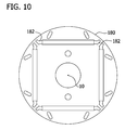
FIGS. 1, 2, 3, 6, 9, 10, 14, 15, and 16 are cross sectional views of embodiments of the invention including four interior magnets, each having two angled slots per magnetic pole.
FIG. 1A is a graph illustrating the back emf of a motor or generator including a rotor having laminations as illustrated in FIG. 1 including angled slots 16.
FIG. 1B is a graph illustrating the back emf of a motor or generator including a rotor having laminations as illustrated in FIG. 1 without angled slots 16.
FIGS. 2A, 3A, 6A, 9A, 10A, 14A, and 15A are graphs illustrating the back emf of a motor or generator including a rotor having laminations as illustrated in FIGS. 2, 3, 6, 9, 10, 14, and 15, respectively, each including angled slots.
FIGS. 4, 5, 7, 8, 11, 12, and 13 are cross sectional views of embodiments of the invention including four interior magnets, each having four angled slots per magnetic pole.
FIGS. 4A, 5A, 7A, 8A, 11A, 12A, and 13A are graphs illustrating the back emf of a motor or generator including a rotor having laminations as illustrated in FIGS. 4, 5, 7, 8, 11, 12, and 13, respectively, each including angled slots.
FIG. 9B is a graph illustrating the cogging torque of a motor or generator including a rotor having laminations as illustrated in FIG. 9 including angled slots 172.
FIG. 11B is a graph illustrating the cogging torque of a motor or generator including a rotor having laminations as illustrated in FIG. 11 including angled slots 202.
FIGS. 17 and 18 are cross sectional views of embodiments of the invention including six interior magnets, each having two angled slots per magnetic pole.
FIGS. 19 and 20 are cross sectional views of embodiments of the invention including two interior magnets, each having two angled slots per magnetic pole.
FIG. 19A is a graph illustrating the flux distribution of a motor or generator including a rotor having laminations as illustrated in FIG. 19 including angled slots 364.
FIG. 19B is a graph illustrating the flux density distribution of a motor or generator including a rotor having laminations as illustrated in FIG. 19 including angled slots 364.
FIG. 21 is a cross sectional view of an embodiment of the invention including twelve interior magnets, arranged to produce six magnetic poles with two angled slots per pole.
FIG. 22 is a cross sectional view of a crown rotor lamination of the prior art without any angled slots according to the invention. The crowning of the pole surface results in a non-uniform air-gap.
FIG. 22A is a graph illustrating the back emf of a non-uniform air-gap motor or generator including a rotor having laminations as illustrated in FIG. 22 according to the prior art without any angled slots.
FIG. 22B is a graph illustrating the cogging torque of a non-uniform air-gap motor or generator including a rotor having laminations as illustrated in FIG. 22 according to the prior art without any angled slots.
FIG. 23 is a cross sectional view of one embodiment of the invention including four interior magnets, each having two angled slots per magnetic pole and having a contiguous, non-magnetic end slot.
FIG. 23A illustrates the embodiment of FIG. 23 including the axes of the peripheral and end slots.
Corresponding reference characters indicate corresponding parts throughout the drawings.
DETAILED DESCRIPTION OF THE INVENTION
In one embodiment, the invention comprises a machine having a stator and a rotor in magnetic coupling engagement with the stator, wherein the rotor has a geometry with angled slots between the magnet surface and the rotor outside diameter. In another embodiment, the invention comprises a rotor geometry with slots added between the magnet surface and the rotor outside diameter. The slots are placed at an angle and in a location that can increase the fundamental component of the rotor flux distribution. The slots may also decrease the cogging torque. A minimum of two slots per magnetic pole are added. Although any even number of slots is illustrated by the embodiments herein, those skilled in the art will recognize other configurations.
The addition of the slots changes the rotor flux distribution from a trapezoidal shape to a more sinusoidal distribution. The fundamental component of the more sinusoidal distribution can be greater than the fundamental component of the trapezoidal distribution, and the harmonic distortion of the distribution can be reduced. Appendix 1 is a mathematical construction of the invention. The first section shows the uniform (trapezoidal) rotor flux distribution without the slots. The FFT fundamental component of the flux distribution is 1.433 amplitude units. The total harmonic distortion of the distribution is 11.805%. The next section of Appendix 1 present a method for calculating the location of the slots. The method presented increases the fundamental component to 1.616 and reduces the THD to 4.263%.
FIGS. 1-21 show a possible implementation of the slots that match the match the mathematical model above. Appendix 2 and FIGS. 19A and 19B show the rotor flux distribution for the rotor in FIG. 19 with and without the slots, as predicted by finite element analysis. The fundamental component of the flux increases by 5.6% with the slot added. The FEA model also shows a significant reduction in the total harmonic distortion of the flux distribution. Note the mathematical model does not account for leakage around the slot.
A comparison of the mathematical model and FEA model can be made using the rotor shown in FIG. 17. This rotor has a reduced leakage path. The FEA model predicts an 11.5% increase in the fundamental flux versus a 12.7% increase predicted by the mathematical model.
The FEA model shows improvement in the shape of the flux distribution, the magnitude of the fundamental component of the flux distribution, average inductance, back-emf fundamental component magnitude, cogging torque magnitude, average torque, and torque ripple.
The location and angle of the slots have not been optimized at this time. Further work is required to optimize these parameters for torque production and cogging torque reduction.
The advantages described above also apply to line start permanent magnet machines. Examples of LSPM rotors are in FIGS. 19 and 20. The angles and locations of the slots may need to be adjusted due to the presence of the cage.
The invention reduces the cogging torque while maintaining or increasing the back-emf and average torque production. This is a highly unusual result. Most methods used for reducing cogging torque also reduce the back-emf and average torque.
The higher back-emf can be taken advantage of in two ways. First, it can be used to increase the power density of the machine, by increasing the torque supplied by a fixed motor or generator size, or by reducing the size of the motor or generator to produce the same torque.
Alternatively, the number of turns could be reduced to keep the same back-emf. The inductance of the machine is proportional to the square of the turns, so a substantial reduction in inductance is possible. A motor or generator using the rotor shown in FIG. 1 with the slots produces 1.9% more torque than a rotor without the slots. Assuming the torque is proportional to the number of turns, reducing the number of turns by 1.9% to produce the same torque with the slots results in a 3.61% decrease in the average inductance.
FIGS. 1-21 illustrate various embodiments of the invention. For convenience, the rotor of the invention is illustrated in cross section as a lamination having slots. In use, the stack of laminations would be fitted with permanent magnets and the slots would be open (i.e., air filled) or filled with a non-magnetic material. For convenience, each lamination is illustrated as including the interior permanent magnets.
Thus, FIG. 1 is an exemplary illustration of one embodiment of a rotor according to the invention. The rotor includes a cylindrical periphery 18 having a central axis of rotation 10. The cross-section of the rotor, as shown in FIG. 1, is taken perpendicular to the central axis 10 and includes the following. A plurality of buried (e.g., interior) permanent magnets 14 are positioned with slots in the rotor, each magnet 14 having a longitudinal dimension which is greater than a transverse dimension (e.g., rectangular in cross section). A plurality of non-magnetic slots 16 are associated with one of the magnets 14, each slot 16 having a longitudinal dimension which is greater than a transverse dimension, wherein an axis of the longitudinal dimension of the slot is not perpendicular to an axis of the longitudinal dimension of its associated interior magnet. Each slot 16 is positioned generally between the periphery 18 and one of the interior magnets 14 with which the slot 16 is associated. Preferably, there are an even number of at least two slots 16 associated with each magnetic pole. An axis of the longitudinal direction of each magnet 14 is substantially parallel to a tangent of the periphery 18 of the cylindrical housing. In one embodiment, the slots 16 are at an angle not equal to 90 degrees relative to the axis of the longitudinal dimension of its associated interior magnet 14.
FIG. 1 is a cross sectional view taken along a perpendicular to a central axis of rotation 10 of a lamination 12 of a rotor according to one embodiment of the invention. Each interior magnet 14 has two associated slots 16 between the magnet 14 and a periphery 18 of the lamination wherein the longitudinal axis 20 of the slots are at an angle of less than 90 degrees relative to a longitudinal axis 22 of its associated interior magnet 14. In this embodiment, each interior magnet 14 has optional end slots 24. The slots 16 and/or the end slots 24 may be filled with air or other non-magnetic material.
In FIGS. 2-16, various lamination embodiments are illustrated, each having four identical quadrants as shown with regard to quadrants A, B, C and D of FIG. 1. For simplicity, only one quadrant is described and labeled with reference characters.
FIG. 2 is a cross sectional view taken along a perpendicular to the central axis of rotation 10 of a lamination 30 of a rotor according to one embodiment of the invention similar to FIG. 1. In this embodiment, the longitudinal axis 32 of the slots 34 are at a greater angle (but less than 90 degrees) relative to a longitudinal axis 36 of its associated interior magnet 38 as compared to the angle of axis 20 illustrated in FIG. 1. In this embodiment, the slots 32 are shorter in length than the slots 16 of FIG. 1.
FIG. 3 is a cross sectional view taken along a perpendicular to the axis of rotation 10 of a lamination 50 of a rotor according to one embodiment of the invention similar to FIG. 1. In this embodiment, the longitudinal axis 52 of the slots 54 are at a lesser angle (but greater than 0 degrees and less than 90 degrees) relative to a longitudinal axis 56 of its associated interior magnet 58 as compared to the angle of axis 20 of the slots 16 illustrated in FIG. 1. In this embodiment, the slots 54 are longer in length than the slots 16 of FIG. 1.
FIG. 4 is a cross sectional view taken along a perpendicular to the axis of rotation 10 of a lamination 72 of a rotor according to one embodiment of the invention. Each interior magnet 74 has four associated slots 76 and 77 between the magnet 74 and a periphery 78 of the lamination wherein the longitudinal axis 80 and 81 of the slots are at an angle of less than 90 degrees relative to a longitudinal axis 82 of its associated interior magnet 74. In this embodiment, each interior magnet 74 has optional slotted ends 84 which may be filled with air or other non-magnetic material. In this embodiment, the two outer slots 76 form a smaller angle with the axis 82 than the two inner slots 77 and the two outer slots 76 are shorter in length than the two inner slots 77.
FIG. 5 is a cross sectional view taken along a perpendicular to the axis of rotation 10 of a lamination 92 of a rotor according to one embodiment of the invention. Each interior magnet 94 has four associated slots 96 and 97 between the magnet 94 and a periphery 98 of the lamination wherein the longitudinal axis 100 and 101 of the slots are at an angle of less than 90 degrees relative to a longitudinal axis 102 of its associated interior magnet 94. In this embodiment, each interior magnet 94 has optional slotted ends 104 which may be filled with air or other non-magnetic material. In this embodiment, the two outer slots 96 form the same angle with the axis 102 than the two inner slots 97 and the two outer slots 96 are shorter in length than the two inner slots 97.
FIG. 6 is a cross sectional view taken along a perpendicular to the axis of rotation 10 of a lamination 110 of a rotor according to one embodiment of the invention similar to FIG. 1. In this embodiment, the longitudinal axis 112 of the slots 114 are at the same angle relative to a longitudinal axis 116 of its associated interior magnet 118 as compared to the angle illustrated of FIG. 1. In this embodiment, the slots 114 are the same length as the slots 16 of FIG. 1. In this embodiment, the longitudinal axis 113 of the slots 115 are at a lesser angle relative to a longitudinal axis 116 of its associated interior magnet 118 as compared to the angle of axis 20 of the slots 16 illustrated in FIG. 1. In this embodiment, the slots 115 are longer in length than the slots 16 of FIG. 1.
FIG. 7 is a cross sectional view taken along a perpendicular to the axis of rotation 10 of a lamination 132 of a rotor according to one embodiment of the invention. This embodiment is the same as FIG. 5 except that slots 134 have a longitudinal axis 136 which is perpendicular relative to a longitudinal axis 138 of its associated interior magnet 140.
FIG. 8 is a cross sectional view taken along a perpendicular to the axis of rotation 10 of a lamination 152 of a rotor according to one embodiment of the invention. This embodiment is the same as FIG. 5 except that slots 154 have a longitudinal axis 156 which is at a lesser angle relative to a longitudinal axis 158 of its associated interior magnet 160 as compared to the angle of axis 101 of slots 97 of FIG. 5.
FIG. 9 is a cross sectional view taken along a perpendicular to the axis of rotation 10 of a lamination 170 of a rotor according to one embodiment of the invention. This embodiment is the same as FIG. 1 except that slots 172 are tear-shaped having one end which is wider than the other end as compared to the slots 16 of FIG. 1. In addition, the slots 172 have a longitudinal axis 174 which is at a lesser angle relative to a longitudinal axis 176 of its associated interior magnet 178 as compared to the angle of axis 20 of the slots 16 of FIG. 1.
FIG. 10 is a cross sectional view taken along a perpendicular to the axis of rotation 10 of a lamination 180 of a rotor according to one embodiment of the invention. This embodiment is the same as FIG. 1 except that end slots 182 are narrower in width than the end slots 24 of FIG. 1.
FIG. 11 is a cross sectional view taken along a perpendicular to the axis of rotation 10 of a lamination 200 of a rotor according to one embodiment of the invention. This embodiment is the same as FIG. 4 except that slots 202 are tear-shaped having one end which is wider than the other end as compared to the slots 76 of FIG. 4. In addition, the slots 202 have a longitudinal axis 204 which is at a lesser angle relative to a longitudinal axis 206 of its associated interior magnet 208 as compared to the angle of axis 80 of the slots 76 of FIG. 4.
FIG. 12 is a cross sectional view taken along a perpendicular to the axis of rotation 10 of a lamination 220 of a rotor according to one embodiment of the invention. This embodiment is the same as FIG. 11 except that slots 222 have a narrower width as compared to the slots 202 of FIG. 11. In addition, the slots 222 have a longitudinal axis 224 which is at a greater angle relative to a longitudinal axis 226 of its associated interior magnet 228 as compared to the angle of axis 204 of the slots 202 of FIG. 11.
FIG. 13 is a cross sectional view taken along a perpendicular to the axis of rotation 10 of a lamination 240 of a rotor according to one embodiment of the invention. This embodiment is the same as FIG. 12 except that slots 242 have a longitudinal axis 244 which is at a lesser angle relative to a longitudinal axis 246 of its associated interior magnet 248 as compared to the angle of axis 224 of the slots 222 of FIG. 12.
FIG. 14 is a cross sectional view taken along a perpendicular to the axis of rotation 10 of a lamination 260 of a rotor according to one embodiment of the invention. This embodiment is the same as FIG. 1 except that one of two slots 262, namely slot 262B, is longer and tear-shaped as compared to the slots 16 of FIG. 1, both of which are the same shape and position. In addition, the tear-shaped slot 262B has a longer length along axis 264B as compared to the slots 16 of FIG. 1. In addition, slot 262B is at a lesser angle relative to a longitudinal axis 266 of its associated interior magnet 268 as compared to the angle of axis 20 of the slots 16 of FIG. 1.
FIG. 15 is a cross sectional view taken along a perpendicular to the axis of rotation 10 of a lamination 280 of a rotor according to one embodiment of the invention. This embodiment is the same as FIG. 1 except that both slots 282 are tear-shaped and slot 282B is longer as compared to the slots 16 of FIG. 1, both of which are the same shape and position. In addition, the tear-shaped slot 282B has a longer length along axis 284B as compared to the slots 16 of FIG. 1. In addition, both tear-shaped slots 282 are at a lesser angle relative to a longitudinal axis 286 of its associated interior magnet 288 as compared to the angle of axis 20 of slots 16 of FIG. 1.
FIG. 16 is a cross sectional view taken along a perpendicular to the axis of rotation 10 of a lamination 290 of a rotor according to one embodiment of the invention. This embodiment is the same as FIG. 1 except that both slots 292 are connected to a slot 294 for an associated interior magnet 296 as compared to FIG. 1 wherein the slots 16 are not connected to the slots for magnets 14. In addition, both slots 292 are at a lesser angle relative to a longitudinal axis 298 of its associated interior magnet 296 as compared to the angle of axis 20 of slots 16 of FIG. 1.
FIG. 17 is a cross sectional view taken along a perpendicular to the axis of rotation 10 of a lamination 300 of a rotor according to one embodiment of the invention. FIG. 17 is similar to FIG. 1 except that it has six interior magnets 302 instead of the four interior magnets 14 of FIG. 1. In addition, FIG. 17 has S-shaped slots 304 instead of the slots 16 of FIG. 1, which are generally shaped rectangular with rounded corners.
FIG. 18 is a cross sectional view taken along a perpendicular to the axis of rotation 10 of a lamination 340 of a rotor according to one embodiment of the invention. In FIG. 18, six interior magnets 342 equally spaced about the periphery are illustrated. Each magnet has a trapezoidal end slot 344 at each end. Each interior magnet 342 has two associated slots 346 between the magnet 342 and a periphery 348 of the lamination 340 and wherein the longitudinal axis 350 of the slots 346 are at an angle of less than 90 degrees relative to a longitudinal axis 352 of its associated interior magnet 342. In this embodiment, each interior magnet 342 is illustrated as having the optional end slots 344. The slots 346 and/or the end slots 344 may be filled with air or other non-magnetic material. In addition, as illustrated in FIG. 18, the slots 346 are not connected to one of the end slots 344. Further, in this embodiment, the at least part of the end slots 344 have an axis 354 which is aligned with a radius 356 of the lamination 340.
FIG. 19 is a cross sectional view taken along a perpendicular to the axis of rotation 10 of a lamination 360 of a rotor according to one embodiment of the invention. In FIG. 19, two parallel interior magnets 362 equally spaced within the periphery are illustrated. Each interior magnet 362 has two associated slots 364 between the magnet 362 and starting cage slots 366 positioned about the periphery 368 of the lamination 360. The longitudinal axis 370 of the slots 364 are at an angle of less than 90 degrees relative to a longitudinal axis 372 of its associated interior magnet 362. The slots 364 and/or the starting cage slots 366 may be filled with air or other non-magnetic material. In addition, as illustrated in FIG. 19, the slots 364 are connected to and integral with one of the starting cage slots 366.
FIG. 20 is a cross sectional view taken along a perpendicular to the axis of rotation 10 of a lamination 380 of a rotor according to one embodiment of the invention. FIG. 20 is the same as FIG. 19 except slots 382 are not connected to any of starting cage slots 384. Instead, in FIG. 20, the slots 382 are independent of the cage slots 384 and are positioned between the cage slots 384 and magnets 386.
FIG. 21 is a cross sectional view taken along a perpendicular to a central axis of rotation 10 of a lamination 400 of a rotor according to one embodiment of the invention. In FIGS. 1-20 above, the interior magnets are positioned parallel to a tangent to the periphery of the rotor lamination. In contrast, in the lamination 400 of FIG. 21 each interior magnet 402R, 402L is part of a V-shaped pair and each is at an angle relative to the tangent to the periphery. Further, each magnet 402R, 402L has at least one associated slot 404R, 404L between the magnet 402R, 402L and a periphery 406 of the lamination. In this embodiment, a longitudinal axis 408R, 408L of the slots 404R, 404L are at an angle of less than 90 degrees relative to a longitudinal axis 410R, 410L of its associated interior magnet 402.
In the embodiment of FIG. 21, the longitudinal axis 408R, 408L of each slot 404R, 404L is not aligned with a radius 412 of the lamination 400, although it is contemplated that the axis 408R, 408L and radius 412 may be aligned. Similarly, in FIGS. 1-20, the slots are not aligned with a radius because the interior magnets are positioned parallel to a tangent to the periphery of the rotor lamination and the slots are paired, with each slot of a pair facing the other slot of the pair. Thus, the slots form an angle of less than 90 degrees with the interior magnets. It is contemplated that the slots may face away from each other in which case the slots may be aligned with a radius of the rotor but the slots would still be at an angle of less than 90 degrees with the interior magnets.
FIG. 22 is an illustration of a crown rotor according to the prior art without any slots. Each interior magnet 420 has an end slot 422, as shown. The end slots of FIGS. 1-18 have a slightly different shape than the end slots 422. In particular, the end slots of FIGS. 1-18 were positioned to be the same distance from the periphery as the end slots 422 to maintain the same flux leakage. A stator 430 is shown in phantom, the stator being in magnetic coupling arrangement with the crown rotor.
FIGS. 23 and 23A are cross sectional views of one embodiment of the invention including four interior magnets, each having two angled slots per magnetic pole and having a contiguous, non-magnetic end slot. The rotor 500 as illustrated comprises a plurality of laminations, each having a cylindrical periphery 502 having a central axis of rotation 504. FIGS. 23 and 23A illustrate the perspective of a cross-section taken perpendicular to the central axis of rotation 504. The rotor 500 includes plurality of interior permanent magnets 506 of rectangular cross section having a longitudinal axis along a chord of the cylindrical periphery 502 which does not intersect the axis of rotation 504. It is also contemplated but not illustrated that the magnets 506 may have a trapezoidal cross-section which can be accommodated by a plurality of non-magnetic end slots 508. Each interior permanent magnet has two poles 510A, 510B and has a longitudinal dimension 512 which is greater than a transverse dimension 514.
In order to reduce cogging, increase the fundamental back-emf, and reduce the back-emf harmonic content, the rotor 500 includes several features in combination. A plurality of non-magnetic peripheral slots 516, 518, 520 and 522, at least one non-magnetic peripheral slot associated with each pole 510 of the interior permanent magnets 506, are positioned between the cylindrical periphery 502 and its associated interior permanent magnet 506. In one embodiment, the slots 516, 518, 520 and 522 vary in length and have substantially the same width and/or at least two non-magnetic peripheral slots are associated with each pole of the interior permanent magnets.
Each non-magnetic peripheral slot 516, 518, 520 and 522 is not contiguous with its associated interior permanent magnet 506 and each non-magnetic peripheral slot has a longitudinal dimension 516L which is greater than a transverse dimension 516T.
The slots 516, 518, 520 and 522 are oriented such that an axis of the longitudinal dimension 516L of each non-magnetic peripheral slot is not perpendicular to an axis of the longitudinal dimension 512 of its adjacent, associated interior permanent magnet 506. The plurality of non-magnetic end slots 508 are each contiguous to and integral with each end of each pole 510 of each interior permanent magnet 506 with at least part of each non-magnetic end slot 508 aligned along a substantially central chord 524 which does not intersect the central axis of rotation 504 (i.e., chord 524 is not a radius or diameter of the rotor). In one embodiment, the end slots 508 have a chord segment 508C having a central axis aligned along a chord of the cylindrical periphery 502 and a radial segment 508R having a central axis generally parallel to a chord of the rotor 500. The central axis of the chord segment 508C forms an obtuse angle with the central axis of the radial segment 508R. The chord segment 508C has a trapezoidal cross section and its central axis, which is parallel to its parallel sides, is aligned with a longitudinal axis 526 of the rectangular magnet 506. Thus, in one embodiment, at least part of each non-magnetic end slot 508 (e.g., the chord segment 508C) has a central axis which is aligned with the longitudinal axis 526 of its associated buried interior permanent magnet 506.
The radial segment 508R of the non-magnetic end slot 508 has longitudinal dimension which is greater than a transverse dimension. The radial segment 508R and its corresponding radial segment 508R′ each have a trapezoidal cross section. Segments 508R and 508R′ are aligned along a substantially central chord 524 which is parallel to their parallel sides. As illustrated in FIG. 23A, adjacent radial segments 508R and 508R′ have parallel substantially central chords 524 along their longitudinal dimension and/or opposite end segments 508R and 508R′ have aligned central axes along their longitudinal dimension. In one embodiment, the longitudinal dimension 512 of the magnet 506 is less than a length 528 of the non-magnetic chord slot receiving the magnet 506 in order to form the trapezoidal non-magnetic chord segment 508C at each end of the magnet 506. It is also contemplated that the longitudinal dimension 512 of the magnet 506 may equal the length 528 of the chord slot so that end slot would only consist of the radial segment 508R and the end slot would not include the chord segment 508C.
In one embodiment, the peripheral slots 516, 518, 520 and 522 and the end slots 508 are spaced substantially the same distance D from the periphery 502.
As shown in FIG. 23A, the rotor 500 is configured such that the cross-section is symmetrical about a chord 530, 532 perpendicular to the interior permanent magnets and intersecting the central axis 504 of rotation. In one embodiment, the chords 516P, 518P, 520P and 522P of the longitudinal dimension of the non-magnetic peripheral slots do not intersect the central chord 524 of rotation 504.
In one embodiment, the rotor 500 comprises a plurality of laminations, each having a cylindrical periphery 502 about a central chord 524 of rotation 504 as illustrated at least in FIGS. 23 and 23A.
In one embodiment, the invention comprises a machine including a stator and the rotor 500 in magnetic coupling engagement with the stator.
TABLE 1 illustrates finite element modeling results regarding the back emf and cogging for the embodiments of FIGS. 1, 2, 3, 4, 5 and 22 having the slot dimensions indicated. Slot 1 refers to the slots in a two slot configuration and the outer slots in a four slot configuration. Slot 2 refers to the inner slots of a four slot configuration.
TABLE 2 illustrates finite element modeling results regarding the back emf and cogging for the embodiments of FIGS. 6, 7, 8, 9, 10 and 11 having the slot dimensions indicated. Slot 1 refers to the slots in a two slot configuration and the outer slots in a four slot configuration. Slot 2 refers to the inner slots of a four slot configuration.
TABLE 3 illustrates finite element modeling results regarding the back emf and cogging for the embodiments of FIGS. 12, 13, 14 and 15 having the slot dimensions indicated. Slot 1 refers to the slots in a two slot configuration and the outer slots in a four slot configuration. Slot 2 refers to the inner slots of a four slot configuration.
TABLE 4 illustrates test results regarding the back emf and cogging for the embodiments of FIGS. 1, 9, 11 and 22 (CROWN) having the slot dimensions indicated.
TABLE 1
FIGS. 1, 2, 3, 4, 5 AND 22.
FIG. 1
Crown W/O
FIG. 21 SLOTS FIG. 1 FIG. 2 FIG. 3 FIG. 4 FIG. 5
Back-EMF
Fundamental Vpk at 2 rpm 0.105 0.106 0.109 0.109 0.109 0.109 0.109
 5th Harmonic % Fund. 0.04 2.52 1.62 1.68 1.8 1.62 1.66
 7th Harmonic % Fund. 0.64 1.22 1.62 1.36 1.79 1.6 1.6
11th Harmonic % Fund. 2.65 8.53 11.38 11.47 5.93 11.31 10.43
13th Harmonic % Fund. 0.09 0.59 3.66 2.76 3.35 3.57 2.82
THD % 0.09 0.86 1.48 1.51 0.69 1.47 1.21
Cogging Nmpk 0.085 0.377 0.085 0.377 0.208 0.083 0.06
Pole Arc edeg 158.94 158.94 158.94 158.94 158.94 158.94
Slot 1 Dimensions
Inner Tangent Arc edeg N/A N/A 111.8 111.8 111.8 111.8 111.8
Inner Radius mm N/A N/A 0.75 0.75 0.75 0.75 0.75
Outer Tangent edeg N/A N/A 87.76 97.36 78.16 87.76 87.76
Arc
Outer Radius mm N/A N/A 0.75 0.75 0.75 0.75 0.75
Slot 2 Dimensions
Inner Tangent Arc edeg N/A N/A N/A N/A N/A 40.88 53.4
Inner Radius mm N/A N/A N/A N/A N/A 0.75 0.75
Outer Tangent edeg N/A N/A N/A N/A N/A 23.36 23.36
Arc
Outer Radius mm N/A N/A N/A N/A N/A 0.75 0.75
TABLE 2
FIGS. 6, 7, 8, 9, 10 AND 11.
FIG. 6 FIG. 7 FIG. 8 FIG. 9 FIG. 10 FIG. 11
Back-EMF
Fundamental Vpk at 2 rpm 0.108 0.108 0.108 0.109 0.107 0.105
 5th Harmonic % Fund. 2.24 1.79 1.68 1.62 1.73 1.91
 7th Harmonic % Fund. 1.56 1.26 1.63 1.68 2.08 1.61
11th Harmonic % Fund. 1.84 9.63 9.24 9.77 8.64 6.16
13th Harmonic % Fund. 5.93 0.33 1.43 1.57 2.83 0.43
THD % 0.5 1.01 0.94 1.05 0.9 0.48
Cogging Nmpk 0.354 0.386 0.086 0.024 0.13 0.096
Pole Arc edeg 158.94 158.94 158.94 158.94 162 158.94
Slot 1 Dimensions
Inner Tangent Arc edeg 111.8 111.8 111.8 111.8 111.8
Inner Radius mm 0.75 0.75 0.75 0.75 0.75
Outer Tangent edeg 100.06 87.76 87.76 87.76 87.76
Arc
Outer Radius mm 0.75 0.75 1.5 0.75 1.5
Slot 2 Dimensions
Inner Tangent Arc edeg 53.4 53.4 N/A N/A 53.4
Inner Radius mm 0.75 0.75 N/A N/A 0.75
Outer Tangent edeg 23.36 18.36 N/A N/A 18.36
Arc
Outer Radius mm 0.75 0.75 N/A N/A 0.75
TABLE 3
FIGS. 12, 13, 14 AND 15.
FIG. 12 FIG. 13 FIG. 14 FIG. 15
Back-EMF
Fundamental Vpk at 2 rpm 0.107 0.105 0.107 0.104
 5th Harmonic % Fund. 1.73 1.82 2.71 2.75
 7th Harmonic % Fund. 1.62 1.6 0.95 0.63
11th Harmonic % Fund. 8.16 7.12 8.48 12.59
13th Harmonic % Fund. 1.03 0.709 5.74 1.98
THD % 0.74 0.59 1.21 1.73
Cogging Nmpk 0.068 0.082 0.295 0.232
Pole Arc edeg 158.94 158.94 158.4 158.4
Slot 1 Dimensions
Inner Tangent Arc edeg 111.8 111.8 111.8 111.8
Inner Radius mm 0.75 0.75 0.75 0.75
Outer Tangent edeg 87.76 87.76 87.76 87.76
Arc
Outer Radius mm 1.125 1.125 0.75 1.5
Slot 2 Dimensions
Inner Tangent Arc edeg 53.4 59.92 114.48 111.8
Inner Radius mm 0.75 0.75 0.75 0.75
Outer Tangent edeg 18.36 18.36 40.28 26.04
Arc
Outer Radius mm 0.75 0.75 1.5 1.5
TABLE 4
FIGS. 1, 9, 11 AND 22
FIG. 1
Crown W/O FIG.
Back-EMF FIG. 22 SLOTS FIG. 1 FIG. 9 11
Maximum Vpk at 51.1 57.3 62.6 58.1 53.1
1000 rpm
Fundamental Vpk at 50.9 53.5 54.8 53.4 50.5
1000 rpm
 5th Harmonic % Fund. 0.75 1.84 0.93 1.01 1.19
 7th Harmonic % Fund. 0.42 0.76 1.18 1.23 1.1
11th Harmonic % Fund. 2.22 7.93 11.34 9.18 5.28
13th Harmonic % Fund. 0.14 1.2 3.58 1.28 1.09
THD % 0.059 0.729 1.46 0.903 0.341
Cogging Nmpk 0.086 0.281 0.037 0.034 0.031
Having described the invention in detail, it will be apparent that modifications and variations are possible without departing from the scope of the invention defined in the appended claims.
When introducing elements of the present invention or the preferred embodiments(s) thereof, the articles “a”, “an”, “the” and “said” are intended to mean that there are one or more of the elements. The terms “comprising”, “including” and “having” are intended to be inclusive and mean that there may be additional elements other than the listed elements.
In view of the above, it will be seen that the several objects of the invention are achieved and other advantageous results attained.
As various changes could be made in the above constructions, products, and methods without departing from the scope of the invention, it is intended that all matter contained in the above description and shown in the accompanying drawings shall be interpreted as illustrative and not in a limiting sense.

Claims (21)

1. A rotor comprising:
a cylindrical periphery having a central axis of rotation;
a cross-section taken perpendicular to the central axis of rotation, said cross-section of the rotor comprising:
a plurality of interior permanent magnets, each interior permanent magnet having two poles and having a longitudinal dimension which is greater than a transverse dimension;
a plurality of non-magnetic peripheral slots, at least one non-magnetic peripheral slot associated with each pole of the interior permanent magnets, each non-magnetic peripheral slot positioned between the cylindrical periphery and its associated interior permanent magnet, wherein each non-magnetic peripheral slot is not contiguous with its associated interior permanent magnet, wherein each non-magnetic peripheral slot has a longitudinal dimension which is greater than a transverse dimension, wherein an axis of the longitudinal dimension of each non-magnetic peripheral slot is not perpendicular to an axis of the longitudinal dimension of its associated interior permanent magnet, and wherein at least one non-magnetic peripheral slot has a substantially different shape than another non-magnetic peripheral slot; and
a plurality of non-magnetic end slots, each non-magnetic end slot contiguous to and integral with each end of each pole of each interior permanent magnet, wherein at least part of each non-magnetic end slot has a central axis which is not aligned with a radius of the rotor.
2. The rotor of claim 1 wherein the non-magnetic peripheral slots associated with each interior permanent magnet pole have different lengths.
3. The rotor of claim 1 wherein at least two non-magnetic peripheral slots are associated with each pole of the interior permanent magnets.
4. The rotor of claim 1 wherein the end slots have a longitudinal dimension which is greater than a transverse dimension and wherein adjacent end slots have parallel central axes along their longitudinal dimension.
5. The rotor of claim 4 wherein opposite end slots have aligned central axes along their longitudinal dimension.
6. The rotor of claim 1 wherein the interior permanent magnets have a rectangular cross-section taken perpendicular to the central axis of rotation.
7. The rotor of claim 1 wherein the peripheral slots and the end slots are spaced substantially the same distance from the periphery.
8. The rotor of claim 1 wherein the cross-section is symmetrical about a line perpendicular to the interior permanent magnets and intersecting the central axis of rotation.
9. The rotor of claim 1 wherein the axis of the longitudinal dimension of each non-magnetic peripheral slot does not intersect the central axis of rotation.
10. A machine comprising a stator and the rotor of claim 1.
11. A rotor comprising:
a cylindrical periphery having a central axis of rotation;
a cross-section taken perpendicular to the central axis of rotation, said cross-section of the rotor comprising:
a plurality of interior permanent magnets, each interior permanent magnet having two poles and having a longitudinal dimension which is greater than a transverse dimension; and
a plurality of non-magnetic peripheral slots, at least one non-magnetic peripheral slot associated with each pole of the interior permanent magnets, each non-magnetic peripheral slot positioned between the cylindrical periphery and its associated interior permanent magnet, wherein each non-magnetic peripheral slot is not contiguous with its associated interior permanent magnet, wherein each non-magnetic peripheral slot has a longitudinal dimension, wherein an axis of the longitudinal dimension of each non-magnetic peripheral slot is not perpendicular to an axis of the longitudinal dimension of its associated interior permanent magnet, and wherein at least one non-magnetic peripheral slot has a substantially different shape than another non-magnetic peripheral slot.
12. The rotor of claim 11 wherein at least one non-magnetic peripheral slot is tear-shaped.
13. A machine comprising a stator and the rotor of claim 11.
14. A rotor comprising:
a cylindrical periphery having a central axis of rotation;
a cross-section taken perpendicular to the central axis of rotation, said cross-section of the rotor comprising:
a plurality of interior permanent magnets, each interior permanent magnet having two poles and having a longitudinal dimension which is greater than a transverse dimension; and
a plurality of non-magnetic peripheral slots, at least one non-magnetic peripheral slot associated with each pole of the interior permanent magnets, each non-magnetic peripheral slot positioned between the cylindrical periphery and its associated interior permanent magnet, wherein each non-magnetic peripheral slot is not contiguous with its associated interior permanent magnet, wherein each non-magnetic peripheral slot has a longitudinal dimension, wherein an axis of the longitudinal dimension of each non-magnetic peripheral slot is not perpendicular to an axis of the longitudinal dimension of its associated interior permanent magnet, and wherein at least one non-magnetic peripheral slot is tear-shaped.
15. The rotor of claim 14 wherein a plurality of non-magnetic peripheral slots are tear-shaped.
16. The rotor of claim 14 wherein the cross-section of the rotor includes only tear-shaped non-magnetic peripheral slots.
17. A machine comprising a stator and the rotor of claim 14.
18. A rotor comprising:
a cylindrical periphery having a central axis of rotation;
a cross-section taken perpendicular to the central axis of rotation, said cross-section of the rotor comprising:
a plurality of interior permanent magnets, each interior permanent magnet having two poles and having a longitudinal dimension which is greater than a transverse dimension; and
a plurality of non-magnetic peripheral slots, at least one non-magnetic peripheral slot associated with each pole of the interior permanent magnets, each non-magnetic peripheral slot positioned between the cylindrical periphery and its associated interior permanent magnet, wherein each non-magnetic peripheral slot is not contiguous with its associated interior permanent magnet, wherein each non-magnetic peripheral slot has a longitudinal dimension, wherein an axis of the longitudinal dimension of each non-magnetic peripheral slot is not perpendicular to an axis of the longitudinal dimension of its associated interior permanent magnet, and wherein at least one non-magnetic peripheral slot is S-shaped.
19. The rotor of claim 18 wherein a plurality of non-magnetic peripheral slots are S-shaped.
20. The rotor of claim 18 wherein the cross-section of the rotor includes only S-shaped non-magnetic peripheral slots.
21. A machine comprising a stator and the rotor of claim 18.
US12/718,642 2006-04-14 2010-03-05 Interior magnet machine with reduced cogging Active 2026-09-24 US8350435B2 (en)

Priority Applications (3)

Application Number Priority Date Filing Date Title
US12/718,642 US8350435B2 (en) 2006-04-14 2010-03-05 Interior magnet machine with reduced cogging
MX2011002440A MX2011002440A (en) 2010-03-05 2011-03-04 Interior magnet machine with reduced cogging.
CN2011100524569A CN102195378A (en) 2010-03-05 2011-03-04 Interior magnet machine with reduced cogging

Applications Claiming Priority (2)

Application Number Priority Date Filing Date Title
US11/279,872 US7705502B2 (en) 2006-04-14 2006-04-14 Interior magnet machine with non-perpendicular slots
US12/718,642 US8350435B2 (en) 2006-04-14 2010-03-05 Interior magnet machine with reduced cogging

Related Parent Applications (1)

Application Number Title Priority Date Filing Date
US11/279,872 Continuation-In-Part US7705502B2 (en) 2006-04-14 2006-04-14 Interior magnet machine with non-perpendicular slots

Publications (2)

Publication Number Publication Date
US20100156234A1 US20100156234A1 (en) 2010-06-24
US8350435B2 true US8350435B2 (en) 2013-01-08

Family

ID=42264965

Family Applications (1)

Application Number Title Priority Date Filing Date
US12/718,642 Active 2026-09-24 US8350435B2 (en) 2006-04-14 2010-03-05 Interior magnet machine with reduced cogging

Country Status (1)

Country Link
US (1) US8350435B2 (en)

Cited By (4)

* Cited by examiner, † Cited by third party
Publication number Priority date Publication date Assignee Title
US9641054B2 (en) 2013-05-17 2017-05-02 General Electric Company Segmented magnet component for electric machine and method of assembly
US10211692B2 (en) * 2016-08-11 2019-02-19 Hiwin Mikrosystems Corp. Permanent magnet motor
US10236742B2 (en) 2014-11-25 2019-03-19 Black & Decker Inc. Brushless motor for a power tool
US10328566B2 (en) 2015-10-14 2019-06-25 Black & Decker Inc. Brushless motor system for power tools

Families Citing this family (7)

* Cited by examiner, † Cited by third party
Publication number Priority date Publication date Assignee Title
EP2602912A2 (en) * 2011-12-05 2013-06-12 Samsung Electronics Co., Ltd Brushless motor
WO2013114542A1 (en) * 2012-01-30 2013-08-08 三菱電機株式会社 Rotor for permanent magnet-embedded electric motor, electric motor provided with same rotor, compressor provided with same electric motor, and air conditioner provided with same compressor
WO2014068655A1 (en) 2012-10-30 2014-05-08 三菱電機株式会社 Electric motor with embedded permanent magnet, and refrigeration and air conditioning equipment equipped with same
WO2018188755A1 (en) * 2017-04-13 2018-10-18 Abb Schweiz Ag Sheet and rotor of electric machine and method of manufacturing them
CN112436624B (en) * 2019-08-26 2022-02-11 安徽美芝精密制造有限公司 Rotor, motor, compressor and refrigeration plant
CN111030339B (en) * 2019-12-16 2022-01-28 珠海格力电器股份有限公司 Electric motor rotor and alternating-pole electric motor
US20230027862A1 (en) * 2021-07-21 2023-01-26 Abb Schweiz Ag Permanent magnet rotor with conductive flux barrier

Citations (11)

* Cited by examiner, † Cited by third party
Publication number Priority date Publication date Assignee Title
US4139790A (en) 1977-08-31 1979-02-13 Reliance Electric Company Direct axis aiding permanent magnets for a laminated synchronous motor rotor
US5672926A (en) 1995-02-21 1997-09-30 Siemens Aktiengesellschaft Hybrid-energized electric machine
JPH10285845A (en) 1997-03-31 1998-10-23 Mitsubishi Electric Corp Permanent magnet type motor and its manufacture
JPH1146464A (en) 1997-07-25 1999-02-16 Sanyo Electric Co Ltd Permanent magnet motor
US6441524B2 (en) 2000-02-25 2002-08-27 Nissan Motor Co., Ltd. Rotor for synchronous motor
JP2005027422A (en) 2003-07-02 2005-01-27 Hitachi Ltd Permanent magnet type rotating electric machine and electric compressor using the same
US20050040723A1 (en) 2002-04-15 2005-02-24 Denso Corporation Permanent-magnet rotor for an inner rotor type electric rotary machine and magnet-saving type rotor for a synchronous motor
WO2005029678A1 (en) * 2003-09-19 2005-03-31 Toshiba Carrier Corporation Permanent magnet motor
JP2005245148A (en) * 2004-02-27 2005-09-08 Mitsubishi Electric Corp Permanent magnet motor, enclosed compressor, and fan motor
US7230359B2 (en) 2002-03-22 2007-06-12 Ebm-Papst St. Georgen Gmbh & Co. Kg Electric motor with poles shaped to minimize cogging torque
US20080018190A1 (en) 2006-07-20 2008-01-24 Ryoichi Takahata Permanent magnet type electric rotary machine and compressor using the same

Patent Citations (12)

* Cited by examiner, † Cited by third party
Publication number Priority date Publication date Assignee Title
US4139790A (en) 1977-08-31 1979-02-13 Reliance Electric Company Direct axis aiding permanent magnets for a laminated synchronous motor rotor
US5672926A (en) 1995-02-21 1997-09-30 Siemens Aktiengesellschaft Hybrid-energized electric machine
JPH10285845A (en) 1997-03-31 1998-10-23 Mitsubishi Electric Corp Permanent magnet type motor and its manufacture
JPH1146464A (en) 1997-07-25 1999-02-16 Sanyo Electric Co Ltd Permanent magnet motor
US6441524B2 (en) 2000-02-25 2002-08-27 Nissan Motor Co., Ltd. Rotor for synchronous motor
US7230359B2 (en) 2002-03-22 2007-06-12 Ebm-Papst St. Georgen Gmbh & Co. Kg Electric motor with poles shaped to minimize cogging torque
US20050040723A1 (en) 2002-04-15 2005-02-24 Denso Corporation Permanent-magnet rotor for an inner rotor type electric rotary machine and magnet-saving type rotor for a synchronous motor
JP2005027422A (en) 2003-07-02 2005-01-27 Hitachi Ltd Permanent magnet type rotating electric machine and electric compressor using the same
WO2005029678A1 (en) * 2003-09-19 2005-03-31 Toshiba Carrier Corporation Permanent magnet motor
US7282827B2 (en) * 2003-09-19 2007-10-16 Kabushiki Kaisha Toshiba Permanent magnet motor
JP2005245148A (en) * 2004-02-27 2005-09-08 Mitsubishi Electric Corp Permanent magnet motor, enclosed compressor, and fan motor
US20080018190A1 (en) 2006-07-20 2008-01-24 Ryoichi Takahata Permanent magnet type electric rotary machine and compressor using the same

Cited By (9)

* Cited by examiner, † Cited by third party
Publication number Priority date Publication date Assignee Title
US9641054B2 (en) 2013-05-17 2017-05-02 General Electric Company Segmented magnet component for electric machine and method of assembly
US10236742B2 (en) 2014-11-25 2019-03-19 Black & Decker Inc. Brushless motor for a power tool
US10523081B2 (en) 2014-11-25 2019-12-31 Black & Decker Inc. Brushless motor for a power tool
US10328566B2 (en) 2015-10-14 2019-06-25 Black & Decker Inc. Brushless motor system for power tools
US10328567B2 (en) 2015-10-14 2019-06-25 Black & Decker Inc. Brushless motor system for power tools
US10500708B2 (en) 2015-10-14 2019-12-10 Black & Decker Inc. Power tool
US10786894B2 (en) 2015-10-14 2020-09-29 Black & Decker Inc. Brushless motor system for power tools
US11951603B2 (en) 2015-10-14 2024-04-09 Black & Decker Inc. Brushless motor system for power tools
US10211692B2 (en) * 2016-08-11 2019-02-19 Hiwin Mikrosystems Corp. Permanent magnet motor

Also Published As

Publication number Publication date
US20100156234A1 (en) 2010-06-24

Similar Documents

Publication Publication Date Title
US7705502B2 (en) Interior magnet machine with non-perpendicular slots
US8350435B2 (en) Interior magnet machine with reduced cogging
KR101231024B1 (en) Consequent pole permanent magnet motor
US7417346B2 (en) Permanent magnet rotating electric machine
US8102091B2 (en) Interior permanent magnet motor including rotor with unequal poles
US7327062B2 (en) Rotor for rotary electric machine
US8436504B2 (en) Stator for an electric machine
JP6903144B2 (en) Permanent magnet type rotary electric machine
US20190190331A1 (en) Rotor and permanent magnet electric motor
US20110018384A1 (en) Motor
JP4901839B2 (en) Electric motor, compressor, blower and ventilation fan
KR20080077262A (en) Dynamo-electric machine
JP2012217249A (en) Rotor and permanent magnet motor
US7535149B2 (en) Permanent-magnet excited synchronous motor
WO2014195999A1 (en) Synchronous motor
JP5419991B2 (en) Permanent magnet synchronous motor
WO2017171037A1 (en) Rotor and method for designing rotor
JP2004336999A (en) Permanent magnet motor
US20190140494A1 (en) Electric motor with low cogging torque
JP2021016205A (en) Synchronous reluctance motor
JP7101869B2 (en) Synchronous reluctance motor
CN113890295A (en) Magnetic steel array of permanent magnet double-rotor motor
KR20220048675A (en) Electric generator with consequent pole structure
CN207150280U (en) P-m rotor and magneto
JP2021136840A (en) motor

Legal Events

Date Code Title Description
AS Assignment

Owner name: EMERSON ELECTRIC CO.,MISSOURI

Free format text: ASSIGNMENT OF ASSIGNORS INTEREST;ASSIGNORS:HOEMANN, KEITH I.;WALLS, TODD A.;REEL/FRAME:024037/0637

Effective date: 20100305

Owner name: EMERSON ELECTRIC CO., MISSOURI

Free format text: ASSIGNMENT OF ASSIGNORS INTEREST;ASSIGNORS:HOEMANN, KEITH I.;WALLS, TODD A.;REEL/FRAME:024037/0637

Effective date: 20100305

STCF Information on status: patent grant

Free format text: PATENTED CASE

FPAY Fee payment

Year of fee payment: 4

MAFP Maintenance fee payment

Free format text: PAYMENT OF MAINTENANCE FEE, 8TH YEAR, LARGE ENTITY (ORIGINAL EVENT CODE: M1552); ENTITY STATUS OF PATENT OWNER: LARGE ENTITY

Year of fee payment: 8

AS Assignment

Owner name: HERMETIC MOTORS LP, MISSOURI

Free format text: TRANSFER AGREEMENT;ASSIGNOR:EMERSON ELECTRIC CO.;REEL/FRAME:063804/0682

Effective date: 20230524

AS Assignment

Owner name: U.S. BANK TRUST COMPANY, NATIONAL ASSOCIATION, AS NOTES COLLATERAL AGENT, MINNESOTA

Free format text: SECURITY INTEREST;ASSIGNOR:COPELAND SCROLL COMPRESSORS LP;REEL/FRAME:064279/0001

Effective date: 20230531

Owner name: ROYAL BANK OF CANADA, AS COLLATERAL AGENT, CANADA

Free format text: SECURITY INTEREST;ASSIGNOR:COPELAND SCROLL COMPRESSORS LP;REEL/FRAME:064278/0879

Effective date: 20230531

Owner name: WELLS FARGO BANK, NATIONAL ASSOCIATION, AS COLLATERAL AGENT, CALIFORNIA

Free format text: SECURITY INTEREST;ASSIGNOR:COPELAND SCROLL COMPRESSORS LP;REEL/FRAME:064280/0549

Effective date: 20230531