WO2020021671A1 - エレベータ装置 - Google Patents
エレベータ装置 Download PDFInfo
- Publication number
- WO2020021671A1 WO2020021671A1 PCT/JP2018/028056 JP2018028056W WO2020021671A1 WO 2020021671 A1 WO2020021671 A1 WO 2020021671A1 JP 2018028056 W JP2018028056 W JP 2018028056W WO 2020021671 A1 WO2020021671 A1 WO 2020021671A1
- Authority
- WO
- WIPO (PCT)
- Prior art keywords
- pulley
- dynamic vibration
- vibration absorber
- elevator apparatus
- spokes
- Prior art date
- Legal status (The legal status is an assumption and is not a legal conclusion. Google has not performed a legal analysis and makes no representation as to the accuracy of the status listed.)
- Ceased
Links
Images










Classifications
-
- B—PERFORMING OPERATIONS; TRANSPORTING
- B66—HOISTING; LIFTING; HAULING
- B66B—ELEVATORS; ESCALATORS OR MOVING WALKWAYS
- B66B7/00—Other common features of elevators
- B66B7/06—Arrangements of ropes or cables
-
- B—PERFORMING OPERATIONS; TRANSPORTING
- B66—HOISTING; LIFTING; HAULING
- B66B—ELEVATORS; ESCALATORS OR MOVING WALKWAYS
- B66B7/00—Other common features of elevators
- B66B7/06—Arrangements of ropes or cables
- B66B7/08—Arrangements of ropes or cables for connection to the cars or cages, e.g. couplings
-
- F—MECHANICAL ENGINEERING; LIGHTING; HEATING; WEAPONS; BLASTING
- F16—ENGINEERING ELEMENTS AND UNITS; GENERAL MEASURES FOR PRODUCING AND MAINTAINING EFFECTIVE FUNCTIONING OF MACHINES OR INSTALLATIONS; THERMAL INSULATION IN GENERAL
- F16F—SPRINGS; SHOCK-ABSORBERS; MEANS FOR DAMPING VIBRATION
- F16F15/00—Suppression of vibrations in systems; Means or arrangements for avoiding or reducing out-of-balance forces, e.g. due to motion
- F16F15/02—Suppression of vibrations of non-rotating, e.g. reciprocating systems; Suppression of vibrations of rotating systems by use of members not moving with the rotating systems
-
- F—MECHANICAL ENGINEERING; LIGHTING; HEATING; WEAPONS; BLASTING
- F16—ENGINEERING ELEMENTS AND UNITS; GENERAL MEASURES FOR PRODUCING AND MAINTAINING EFFECTIVE FUNCTIONING OF MACHINES OR INSTALLATIONS; THERMAL INSULATION IN GENERAL
- F16F—SPRINGS; SHOCK-ABSORBERS; MEANS FOR DAMPING VIBRATION
- F16F15/00—Suppression of vibrations in systems; Means or arrangements for avoiding or reducing out-of-balance forces, e.g. due to motion
- F16F15/10—Suppression of vibrations in rotating systems by making use of members moving with the system
- F16F15/12—Suppression of vibrations in rotating systems by making use of members moving with the system using elastic members or friction-damping members, e.g. between a rotating shaft and a gyratory mass mounted thereon
- F16F15/121—Suppression of vibrations in rotating systems by making use of members moving with the system using elastic members or friction-damping members, e.g. between a rotating shaft and a gyratory mass mounted thereon using springs as elastic members, e.g. metallic springs
Definitions
- the present invention relates to an elevator apparatus provided with a pulley provided with a dynamic vibration absorber capable of suppressing rotational vibration.
- the present invention has been made in order to solve the above-described problems, and has a simple configuration in which a dynamic vibration absorber capable of coping with a secular change of a reference resonance frequency to be damped of a rotating system is attached to a pulley in advance. It is an object of the present invention to obtain an elevator apparatus including a dynamic vibration absorber that does not reduce vibration damping performance.
- the elevator apparatus includes a hoistway, a hoisting means, a suspending means for suspending a counterweight arranged in the hoistway, and a counterweight that moves up and down in conjunction with the car, and a hoisting means.
- a car suspension pulley mounted on a car, each having a rotation center, a plurality of spokes extending radially from the rotation center, and an outer periphery supported by the spokes, and a counterweight.
- a counterweight suspending pulley mounted on the at least one pulley of the car suspension pulley and the counterweight suspending pulley, the fixed end being fixed to the center of rotation of the pulley at one end, Consists of a plate-like member having a free end extending in the radial direction and having elasticity in the rotation direction of the pulley, a weight is fixed at any position from the fixed end to the free end of the plate-like member, and in the rotation direction of the pulley. Vibration possible And a a dynamic vibration reducer.
- the elevator apparatus of the present invention for a plurality of dynamic vibration absorbers arranged in the pulley, a combination of different resonance frequencies can be easily set, so that the reference resonance frequency of the rotating system generated by aging with respect to the rigidity of the suspension means. Since the change can be adjusted in advance, it is possible to obtain an elevator apparatus including a dynamic vibration absorber that can stably suppress rotational vibration generated in the pulley with a simple apparatus configuration.
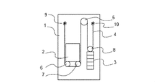
- FIG. 1 is a configuration diagram of an elevator apparatus according to a first embodiment of the present invention. It is a figure which shows the installation pulley of the dynamic vibration absorber corresponding to three types of rotational vibration modes of an elevator apparatus. It is explanatory drawing which shows the relationship between the raising / lowering position of a car and resonance frequency in three types of rotational vibration modes of an elevator apparatus. It is a block diagram of the elevator apparatus in which the return pulley exists. It is explanatory drawing which shows the structure of the pulley of an elevator apparatus. It is explanatory drawing which shows the installation state of the dynamic vibration absorber installed in the pulley of an elevator apparatus. It is a block diagram of the dynamic vibration absorber of Embodiment 1 of this invention.
- FIG. 1 is a configuration diagram of an elevator apparatus according to a first embodiment of the present invention. It is a figure which shows the installation pulley of the dynamic vibration absorber corresponding to three types of rotational vibration modes of an elevator apparatus. It is explanatory drawing which shows the relationship between the raising
- FIG. 4 is an explanatory diagram illustrating an example of fixing a leaf spring and a mounting plate of the dynamic vibration absorber according to Embodiment 1 of the present invention.
- FIG. 4 is a developed view of an example in which the leaf spring and the mounting plate of the dynamic vibration absorber according to Embodiment 1 of the present invention are integrally formed.
- FIG. 4 is a developed view of an example in which the leaf spring and the mounting plate of the dynamic vibration absorber according to Embodiment 1 of the present invention are integrally formed.
- FIG. 4 is an explanatory diagram showing an example in which the integrally formed plate spring and the mounting plate of the dynamic vibration absorber according to Embodiment 1 of the present invention are fastened to the center of rotation of the pulley.
- FIG. 4 is an explanatory diagram showing an installation state of even-numbered dynamic vibration absorbers having different resonance frequencies when the number of spokes is an even number in the pulley of the elevator apparatus according to Embodiment 1 of the present invention.
- FIG. 3 is an explanatory diagram showing an arrangement state of an adjustment mass on an outer peripheral portion for suppressing an uneven load of the pulley when the number of spokes is even in the pulley of the elevator device according to Embodiment 1 of the present invention.
- It is a block diagram of the pendulum type dynamic vibration absorber in a pulley.
- FIG. 10 is an explanatory diagram showing an installation state of odd-numbered dynamic vibration absorbers having different resonance frequencies when the number of spokes is an odd number in the pulley of the elevator apparatus according to Embodiment 2 of the present invention. It is explanatory drawing which shows the arrangement
- FIG. 10 is an explanatory diagram showing an installation state of a plurality of dynamic vibration absorbers having different resonance frequencies when the number of spokes is even in a pulley of an elevator apparatus according to Embodiment 3 of the present invention.
- FIG. 14 is an explanatory diagram showing an installation state of a plurality of dynamic vibration absorbers having different resonance frequencies when the number of spokes is an even number in a pulley of an elevator apparatus according to Embodiment 4 of the present invention. It is an explanatory view showing an installation state of a plurality of dynamic vibration absorbers having different resonance frequencies when the number of spokes is even in a pulley of an elevator apparatus according to Embodiment 5 of the present invention.
- FIG. 16 is an explanatory diagram showing an installation state of a plurality of dynamic vibration absorbers having different resonance frequencies when the number of spokes is an even number in a pulley of an elevator apparatus according to Embodiment 6 of the present invention.
- FIG. 16 is an explanatory diagram showing an installation state of a plurality of dynamic vibration absorbers having different resonance frequencies when the number of spokes is even in a pulley of an elevator apparatus according to Embodiment 7 of the present invention. It is an explanatory view showing the installation state of the dynamic vibration absorber attached to the spoke of the pulley of the elevator apparatus according to Embodiment 8 of the present invention.
- FIG. 1 is a configuration diagram of the elevator apparatus according to the first embodiment of the present invention.
- a car 2 and a counterweight 3 are installed in the hoistway 1.
- the car 2 and the counterweight 3 that moves up and down in conjunction with the car 2 are wound by suspension means 4 on pulleys such as a car suspension pulley 6, a car suspension pulley 7, and a counterweight suspension pulley 8 mounted on the car 2. It is connected by being hung.
- the suspension means 4 a plurality of ropes or a plurality of belts are used.
- a car-side cleat 9 and a counterweight-side cleat 10 are attached to both ends of the suspension means 4, respectively.
- the car 2 runs up and down the hoistway 1 by the suspension means 4 wound around the sheave 5 driven by the hoist.
- a pair of car guide rails (not shown) for guiding the elevator of the car 2 and a pair of counterweight guide rails (not shown) for guiding the lifting of the counterweight 3 are installed in the hoistway 1.
- a car buffer (not shown) for buffering the collision of the car 2 with the hoistway bottom and a counterweight buffer for buffering the collision of the counterweight 3 with the hoistway bottom are provided at the bottom of the hoistway 1.
- a vessel (not shown) is provided.
- FIG. 2 is a diagram illustrating three types of rotational vibration modes of the elevator apparatus.
- 2A shows the state of mode 1
- FIG. 2B shows the state of mode 2 on the lowest floor of the car
- FIG. 2C shows the state of mode 2 on the top floor of the car.
- the pulley on which the effect of the excitation force is greatest and the corresponding dynamic vibration absorber is to be installed is shaded.
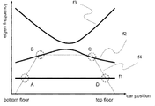
- FIG. 3 is a diagram schematically illustrating a relationship between a car position and a resonance frequency with respect to rotational vibration of the elevator apparatus.
- the vertical axis represents the rotation frequency (eigen frequency)
- the horizontal axis represents the car position (car position) on the hoistway, from the bottom floor (bottom floor) to the top floor (top floor) of the hoistway. .
- FIG. 2A shows a mode (mode) in which all the pulleys (the sheave 5, the car suspension pulleys 6, 7, and the counterweight suspension pulleys 8) rotate and vibrate in the same direction with respect to the traveling direction of the rope during the ascent and descent. 1), and the rotation frequencies of the car suspension pulleys 6 and 7 and the counterweight suspension pulley 8 are as shown by f1 in FIG. 3 and are substantially constant regardless of the car position.
- FIG. 2B shows a mode in which the car suspension pulleys 6 and 7 and the sheave 5 rotate in directions opposite to each other near the lowest floor (mode 2), and the rotational vibration of the car suspension pulleys 6 and 7 is the lowest.
- FIG. 2C shows a mode (mode 2) in which the car is in the vicinity of the top floor where the counterweight suspension pulley 8 and the sheave 5 rotate in opposite directions to each other (mode 2), and the rotational vibration of the counterweight suspension pulley 8 is the largest.
- the rotation frequency is shown on the top floor side of f2 in FIG.
- the waveform becomes a trapezoidal waveform dependent on the rotation speed as indicated by f4 in FIG.
- f4 intersects f1, f2, and f3
- resonance of the rotating system occurs, and large rotational vibration occurs in the pulley.
- the resonance frequencies A and D have the same value. Therefore, in order to reduce the most influential resonance in the above-described three types of vibration modes, as shown in FIG. 2, any one of the two car suspension pulleys 6, 7, for example, FIG.
- a dynamic vibration absorber corresponding to the resonance frequency A (equivalent to D) with f1 is set in the car suspension pulley 6 shown by hatching.
- a dynamic vibration absorber corresponding to the resonance frequency B with f2 is set in another hanging pulley, for example, a car hanging pulley 7 shown by hatching in FIG. 2B.
- a dynamic vibration absorber is set on the counterweight suspending pulley 8 shown by hatching in FIG. 2C so that the counterweight suspending pulley 8 corresponds to the resonance frequency C.
- the resonance frequencies to be damped (for example, the resonance frequencies A and D having the same value shown in FIG. Frequency B, C) is set as a reference resonance frequency, and by increasing or decreasing the frequency with respect to this reference resonance frequency, a plurality of dynamic vibration absorbers set at different resonance frequencies are arranged. Two rotational vibrations can be effectively suppressed.
- the above description of the installation mode of the dynamic vibration absorber includes the elevator apparatus using the 2: 1 roping method in which the sheave 5 is installed above the hoistway 1 shown in FIG. 1 and the sheave shown in FIG. 5 is installed at the lower part of the hoistway 1, and a car return pulley 26 and a counterweight pulley 27 are installed at the upper part of the hoistway 1.
- the dynamic vibration absorber may be installed on the car return pulley 26 or the counterweight return pulley 27.
- the installation mode of the dynamic vibration absorber in the elevator apparatus according to the present invention is similar to that of the counterweight weight pulley above the counterweight 3 in an elevator apparatus in which one car pulley 6 is installed above the car 2. Also applicable to:
- FIG. 5 shows a basic configuration of a car hanging pulley 6 which is an example of the pulley.
- the car suspension pulley 6 includes a rotation center 11 serving as a rotation center, an outer periphery 12 around which the suspension means 4 is wound, and a plurality of spokes 13 connecting the rotation center 11 and the outer periphery 12.
- An air gap 14 is provided between the spokes 13 to reduce the weight of the car suspension pulley.
- the beam material for supporting the car suspension pulley is arranged close to the car suspension pulley in the rotation axis direction, there is almost no gap between the beam material and the car suspension pulley.
- the suspension means 4 and the stopper (not shown) of the suspension means 4 are installed in the radial direction outside the outer periphery of the car suspension pulley, it is difficult to install additional members. Therefore, when the dynamic vibration absorber for suppressing the rotational vibration of the car suspension pulley is installed, it is preferable that the dynamic vibration absorber is housed in the gap 14 of the car suspension pulley in consideration of the miniaturization of the dynamic vibration absorber. The same applies to the counterweight hanging pulley.
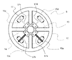
- FIG. 6 shows an installation state of an even number of dynamic vibration absorbers 15 in the car suspension pulley 6.
- the dynamic vibration absorber 15 is constituted by a weight 18 supported by a plate-like member 37, is installed in the space 14 between the spokes 13 of the car suspension pulley 6, one end of which is fixed to the rotation center portion 11, and It can vibrate with elasticity in the rotation direction.
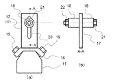
- FIG. 7 shows a configuration of the dynamic vibration absorber 15.
- FIG. 7A shows the dynamic vibration absorber fixed to the rotation center portion 11 as viewed from the side of the car suspension pulley 6, and FIG.
- FIG. 7B shows the dynamic vibration absorber as viewed from the front of the car suspension pulley 6.
- the cantilevered leaf spring 17 having elasticity is used as the plate-like member 37 of the dynamic vibration absorber 15.
- a weight 18 is attached to the free end of the leaf spring 17 extending in the radial direction.
- the mounting plate 16 is fixed to the rotation center portion 11 of the car suspension pulley 6 with bolts 19, and the fixed end of the leaf spring 17 of the dynamic vibration absorber 15 is fixed to the mounting plate 16.
- the plate spring 17 is provided with a long hole 20 in the radial direction.
- the weight 18 is fixed by the bolt 21 and the nut 22 through the elongated hole 20 of the leaf spring 17. The radial position of the weight 18 can be adjusted within the range of the elongated hole 20.
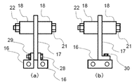
- FIG. 8 shows another example of fixing the leaf spring 17 of the dynamic vibration absorber 15 and the mounting plate 16.
- welding may be used, or as shown in FIG. 8A, a method in which the leaf spring 17 is sandwiched between the divided mounting plates 16 and fixed with bolts 28 and nuts 29. good.
- the leaf spring 17 may be bent in an L shape and fixed to the mounting plate 16 with bolts 30.
- 9 and 10 show a configuration example of a dynamic vibration absorber 15 in which a plate spring 17 and a mounting plate 16 are integrally formed by bending a plate member having elasticity.
- the same shape as the configuration example in FIG. 7 can be realized by folding the broken line of the mounting plate 16 at the mountain and folding the dashed line at the valley.
- the mounting plate 16 is provided with a plurality of screw holes 23.
- the broken line of the mounting plate 16 is folded in a mountain, and the dashed line is folded in a valley.
- FIG. 11 shows a fastening state with the rotation center portion 11.
- a plurality of screw holes 31 are provided in the mounting plate 16 portion.
- a portion where the mounting plate 16 is bent and the rotation center portion 11 is sandwiched is fastened with a bolt 32 and a nut 33.
- the leaf spring 17 is provided with an elongated hole 20, and the weight 18 is fixed by the bolt 21 and the nut 22 through the elongated hole 20 of the leaf spring 17.
- the dynamic vibration absorber 15 can be installed in the gap 14 of the pulley, and the action of the dynamic vibration absorber 15 can suppress the rotational vibration of the pulley.
- the mounting plate 16 of the dynamic vibration absorber 15 is fixed to the rotation center portion 11 of the pulley, the weight 18 is more easily installed on the outer peripheral portion 12 side, and the rotational inertia generated by the weight 18 acts greatly.
- the dynamic vibration absorber 15 can be downsized.
- the plate spring 17 used for the plate member 37 can be set to be longer in the radial direction from the rotation center portion 11, the elongated hole 20 can also be made longer in the radial direction, so that the adjustment width for adjusting the position of the weight 18 is set to be larger. It is possible to do. Thereby, the setting range of the resonance frequency of the dynamic vibration absorber can be widened.
- FIG. 12 is an explanatory diagram illustrating an installation state of a plurality of dynamic vibration absorbers having different resonance frequencies in the pulley of the elevator apparatus.
- the dynamic vibration absorber 15 in the pulley shown in FIG. 12 four dynamic vibration absorbers 15a, 15b, 15c, and 15d are arranged in one pulley.
- the installation position of the weight 18 of each dynamic vibration absorber is different.
- a plurality of dynamic vibration absorbers 15a, 15b, 15c, and 15d, in which the positions of the weights 18 are adjusted to be different from each other, are provided in advance by assuming a change in the reference resonance frequency to be damped due to the aging of the suspension means 4.
- the influence of the change in the reference resonance frequency due to the predicted aging of the suspension means 4 can be minimized.
- the circumference indicated by the broken line is the reference position of the weight corresponding to the reference resonance frequency to be damped.
- the dynamic vibration absorbers 15a and 15c arranged symmetrically with respect to the rotation center of the pulley shift the position of the weight 18 toward the rotation center, that is, the first distance 38, with respect to the reference position. For this reason, the resonance frequencies of the dynamic vibration absorbers 15a and 15c are higher than the resonance frequency of the rotating system to be damped.
- a pair of dynamic vibration absorbers 15b and 15d symmetrically arranged with respect to the center of rotation of the pulley shifts the position of the weight 18 toward the outer peripheral portion, that is, the second distance 39 with respect to the reference position. ing. For this reason, the resonance frequencies of the dynamic vibration absorbers 15b and 15d are lower than the resonance frequency of the rotating system to be damped.
- the natural frequency f (unit: Hz) of the dynamic vibration absorber 15 when one end has a weight at the other end of the leaf spring supported by the rotation center portion 11 is It is.
- EI Young's modulus
- I the second moment of area
- M the mass of the weight
- L the distance from the support point of the leaf spring 17 to the weight 18 and represents the installation position of the weight 18.
- the equation (1) the reference resonant frequency f 0 to be damped, the installation position L 0 of the weight 18, It is.
- the resonance frequency of the dynamic vibration absorber 15 can be easily set and adjusted.
- a set of dynamic vibration absorbers 15 having a resonance frequency higher than the reference resonance frequency is arranged symmetrically with respect to the center of rotation of the pulley, and another one of the resonance frequencies lower than the reference resonance frequency is provided.
- the combination of the dynamic vibration absorbers 15 provided in one pulley and having different resonance frequencies allows the reference resonance frequency of the suspension means 4 to change with time.
- a vibration suppression effect corresponding to the change can be obtained.
- no offset load of the pulley occurs. If the distance displaced from the installation position of the weight 18 symmetrically disposed with respect to the rotation center of the pulley is not the same distance, an uneven load on the pulley occurs due to the difference in the weight position.
- the plate-like member 37 of the dynamic vibration absorber 15 uses a metal plate instead of the leaf spring 17, and is supported by an elastic spring 35.
- the installation position of the weight 18 on the plate-shaped member 37 instead of the pendulum-type configuration that rotates about the fulcrum 34, it is possible to similarly install dynamic vibration absorbers having different resonance frequencies on one pulley.
- the dynamic vibration absorber 15 corresponding to the reference resonance frequency to be damped can be installed in each pulley of the elevator apparatus. Furthermore, since the installation position of the weight of the dynamic vibration absorber 15 can be adjusted without an eccentric load acting on the pulley, by installing a dynamic vibration absorber having a different resonance frequency on one pulley in advance, the vibration damping target can be adjusted. Thus, an elevator apparatus that maintains vibration suppression performance in accordance with the secular change of the reference resonance frequency is obtained.
- FIG. 15 shows a configuration example in which the number of spokes is an odd number and an odd number of dynamic vibration absorbers 15 are mounted in the pulley in the elevator apparatus according to the second embodiment of the present invention.
- the configuration of the rotation mode of the elevator apparatus according to each of the embodiments after the second embodiment and the installation mode of the dynamic vibration absorber 15 in the plurality of pulleys in the elevator apparatus are the same as those of the elevator apparatus according to the first embodiment. Therefore, the description is omitted.
- the configuration example of the dynamic vibration absorber in the pulley in FIGS. 12 and 13 is a case where the number of spokes of the pulley is even.
- the dynamic vibration absorber may be arranged symmetrically with respect to the rotation center of the pulley. it can.
- the number of spokes is odd, for example, when the number of spokes shown in FIG. 15 is five, the dynamic vibration absorbers 15a, 15b, 15c, 15d, and 15e are installed at equal intervals between the spokes. .
- the weight 18 of one dynamic vibration absorber 15d When the weight 18 of one dynamic vibration absorber 15d is installed at a position L 0 + ⁇ L from the reference position L 0 shown by the dashed circle to the outer peripheral side, it is adjacent to a position facing the rotation center of the pulley.
- the weights 18 of the dynamic vibration absorbers 15a and 15b are also installed from the outer peripheral side.
- the weight 18 is installed near the center of rotation so that an uneven load does not act on the pulley.
- the installation position of the weight 18 of each dynamic vibration absorber specifically, when the installation position of the weight of the dynamic vibration absorber 15d is set to L 0 + ⁇ L, the installation position of the weight of the dynamic vibration absorbers 15a and 15b is changed. , L 0 , and the installation position of the weight of the dynamic vibration absorbers 15c, 15e is L 0 ⁇ (1 /) ⁇ ⁇ L.
- the adjusting masses 36a, 36b, 36c, 36d, and 36e may be attached to the outer peripheral portion 12 of the pulley as shown in the configuration example of the dynamic vibration absorber in the pulley in FIG.
- the plate-like member 37 of the dynamic vibration absorber 15 uses a metal plate instead of the leaf spring 17, and is supported by an elastic spring 35. It may be replaced with a pendulum type configuration that rotates around the fulcrum 34.
- the dynamic vibration absorber in the pulley in the elevator apparatus of the second embodiment even if an odd number of dynamic vibration absorbers are installed in one pulley, the dynamic vibration absorber does not act on the pulley without an eccentric load. Since the installation position of the 15 weights can be adjusted, by installing dynamic absorbers with different resonance frequencies in one pulley in advance, the damping performance can be adjusted in accordance with the secular change of the reference resonance frequency to be damped. Is obtained.
- FIG. 17 shows the configuration of the dynamic vibration absorber 15 used in the elevator apparatus according to Embodiment 3 of the present invention
- FIG. 18 shows the installed state of the dynamic vibration absorber 15 in the pulley.
- the resonance frequency of the dynamic vibration absorber 15 is set by adjusting the installation position of the weight 18, but in the third embodiment, the resonance frequency is changed by changing the mass of the weight 18.
- the elongated hole 20 is not provided in the leaf spring 17 of the dynamic vibration absorber 15, and the weight 18 is fixed at a specific position of the leaf spring 17, that is, at the same distance from the center of rotation.
- a plurality of adjustment weights 24 for mass adjustment are arranged on the weight 18. By changing the number (or mass) of the adjustment weights 24, a desired resonance frequency can be set.
- the dynamic vibration absorbers 15a and 15c have the same weight, the dynamic vibration absorbers 15b and 15d have the same weight, and the dynamic vibration absorbers 15a and 15c have the same weight as the dynamic vibration absorbers 15b and 15d. different. That is, as in the first embodiment, in one pulley, a pair of dynamic vibration absorbers 15 having a resonance frequency higher than the reference resonance frequency are symmetrically arranged with respect to the rotation center of the pulley, and By arranging another set of dynamic vibration absorbers 15 having a resonance frequency lower than the frequency symmetrically with respect to the rotation center of the pulley, the mass of the weight 18 symmetrically arranged with respect to the rotation center of the pulley can be relatively reduced.
- the example in which the number of spokes is an even number has been described.
- the mass adjustment of each weight is performed.
- a combination of dynamic vibration absorbers having different resonance frequencies can be installed so that an unbalanced load does not act on the pulley.
- the plate-like member 37 of the dynamic vibration absorber 15 uses a metal plate instead of the leaf spring 17, and centers on a rotation fulcrum 34 supported by an elastic spring 35. May be replaced by a pendulum type configuration that rotates.
- the dynamic vibration absorber in the pulley of the elevator apparatus of the third embodiment the dynamic vibration absorber having a different resonance frequency is installed in one pulley in advance without an uneven load acting on the pulley.
- An elevator apparatus that maintains vibration damping performance in accordance with the secular change of the reference resonance frequency to be vibrated can be obtained.
- FIG. FIG. 19 shows the installation state of the dynamic vibration absorber in the pulley in the elevator apparatus according to Embodiment 4 of the present invention.
- the fourth embodiment by changing the plate thickness of the leaf spring 17 of the dynamic vibration absorber 15, the fluctuation amount of the resonance frequency of the dynamic vibration absorber 15 can be adjusted to a large extent. Further, by finely adjusting the installation position of the weight 18, the resonance frequency of the dynamic vibration absorber 15 can be set to a predetermined value.
- the leaf spring 17 of the dynamic vibration absorber 15 is provided with the elongated hole 20 so that the installation position of the weight 18 can be adjusted.
- the car suspension pulley 6 has a plurality of dynamic springs in which the thickness of the leaf spring 17 is changed with respect to a change in the reference resonance frequency to be damped, which is predicted to occur due to the aging of the suspension means 4.
- the vibration absorbers 15a, 15b, 15c, and 15d By installing the vibration absorbers 15a, 15b, 15c, and 15d, it is possible to cope with fluctuations in the resonance frequency in a wide range.
- the final frequency setting is performed by finely adjusting the position of the weight 18.
- the adjustment amount of the installation position of the weight 18 can be reduced, the influence of the inertial force acting on the pulley by the dynamic vibration absorber is small.
- a pair of dynamic vibration absorbers 15a and 15c in which the weight 18 is installed on the rotation center side is symmetrically arranged with respect to the rotation center of the pulley.
- another set of dynamic vibration absorbers 15b and 15d in which the weight 18 is installed on the outer peripheral side is symmetrically arranged with respect to the rotation center of the pulley. This can prevent an uneven load on the pulley due to the installation position of the weight 18.
- the same effect can be obtained by adjusting the mass of the weight 18 instead of adjusting the installation position of the weight 18.
- the dynamic vibration absorber in the pulley of the elevator apparatus As described above, according to the dynamic vibration absorber in the pulley of the elevator apparatus according to the fourth embodiment, the dynamic vibration absorber having a different resonance frequency is installed in one pulley in advance without applying an eccentric load to the pulley. An elevator apparatus that maintains vibration suppression performance in accordance with the secular change of the reference resonance frequency to be damped is obtained.
- FIG. 20 is an explanatory diagram illustrating an installation state of a dynamic vibration absorber in a pulley in an elevator apparatus according to Embodiment 5 of the present invention.
- the amount of change in the resonance frequency of the dynamic vibration absorber 15 is adjusted by changing the thickness of the leaf spring 17 of the dynamic vibration absorber 15. Further, no elongated hole is provided in the leaf spring 17, and the weight 18 is fixed at a specific position. A change in the reference resonance frequency to be damped due to aging can be handled by installing a plurality of dynamic vibration absorbers 15a, 15b, 15c, and 15d in which the thickness of the leaf spring 17 is changed. As shown in FIG.
- the positions of the weights 18 of the dynamic vibration absorbers 15a, 15b, 15c, and 15d are arranged on the pulley at the same distance from the rotation center of the pulley indicated by a broken line, and all the weights 18 are the same. Mass. As a result, the inertial force acting on the pulley by the dynamic vibration absorber is completely canceled, so that the eccentric load does not act on the pulley. Since the difference in mass due to the difference in thickness of the leaf spring 17 is smaller than that of the weight, it is not necessary to consider the influence of the unbalanced load acting on the pulley.
- the dynamic vibration absorbers having the thicker or thinner plate springs symmetrically with respect to the center of rotation of the pulley, but to place them adjacent to each other. May be arranged.
- the leaf springs of the dynamic vibration absorbers 15a and 15b are thicker (17a and 17b indicated by thick lines), and the leaf springs of the dynamic vibration absorbers 15c and 15d are provided. Is also permissible in a mode in which the plate thickness is smaller (17c and 17d indicated by thin lines).
- the dynamic vibration absorber in the pulley in the elevator apparatus can be arranged at an arbitrary position without considering the uneven load of the pulley caused by the change in the installation position of the weight. Can be simplified. Similarly, without uneven loads acting on the pulleys, by installing dynamic absorbers having different resonance frequencies on one pulley in advance, it is possible to respond to the secular change of the reference resonance frequency to be predicted as a vibration damping target. An elevator device that maintains vibration suppression performance is obtained.
- FIG. 21 is an explanatory diagram illustrating an installation state of a dynamic vibration absorber in a pulley in an elevator apparatus according to Embodiment 6 of the present invention.
- the dynamic vibration absorber has a pendulum type configuration that rotates around a rotation fulcrum 34 supported by an elastic spring 35, as in FIG. 14 described above.
- the installation positions of the weights 18 of the dynamic vibration absorbers 15a, 15b, 15c, and 15d are arranged on the pulley at the same distance from the rotation center of the pulley indicated by broken lines.
- the weight 18 has the same mass.
- the fluctuation amount of the resonance frequency of the dynamic vibration absorber 15 is adjusted by changing the plate thickness of the leaf spring 17 of the dynamic vibration absorber.
- the resonance frequency of the dynamic vibration absorber 15 is changed by changing the strength of the rigidity of the elastic spring 35 attached to the vibration damper 15. That is, in FIG. 21, the elastic springs 35b and 35d attached to the pair of dynamic vibration absorbers 15b and 15d arranged symmetrically with respect to the rotation center of the pulley have stronger spring constants, whereas The elastic springs 35a and 35c attached to the pair of dynamic vibration absorbers 15a and 15c have relatively weak spring constants.
- the dynamic vibration absorbers having stronger or weaker elastic springs need not necessarily be arranged symmetrically with respect to the rotation center of the pulley, and may be arranged adjacent to each other.
- the dynamic vibration absorber in the pulley in the elevator apparatus according to the sixth embodiment, can be arranged without considering the uneven load of the pulley caused by the variation of the installation position of the weight.
- the installation means can be simplified.
- dynamic absorbers having different resonance frequencies on one pulley in advance it is possible to respond to the secular change of the reference resonance frequency to be predicted as a vibration damping target. An elevator device that maintains vibration suppression performance is obtained.
- FIG. FIG. 22 is an explanatory diagram illustrating an installation state of a dynamic vibration absorber in a pulley in an elevator apparatus according to Embodiment 7 of the present invention.
- the seventh embodiment has a pendulum type configuration in which the dynamic vibration absorber rotates about a rotation fulcrum 34, as in the sixth embodiment shown in FIG.
- the weight positions of the dynamic vibration absorbers 15a, 15b, 15c, and 15d are arranged at the same distance from the rotation center of the pulley indicated by a broken line, and all the weights 18 have the same mass. I have to.
- the dynamic vibration absorber 15 has the same spring constant, and by changing the spring 35 to a position radially distant from the rotation fulcrum 34, the dynamic vibration absorber 15 The resonance frequency has been changed.
- the fixed positions of the springs of the dynamic vibration absorbers 15a and 15c are located closer to the outer periphery, and the fixed positions of the springs of the dynamic vibration absorbers 15b and 15d are located closer to the rotation center.
- the weights 18 are arranged at the same distance from the center of rotation of the pulley, the inertial force acting on the pulley is completely canceled by the dynamic vibration absorber, so that the eccentric load does not act on the pulley.
- the dynamic vibration absorber in the pulley in the elevator apparatus according to the seventh embodiment, can be arranged without considering the uneven load of the pulley caused by the change in the installation position of the weight.
- the installation means can be simplified.
- a dynamic vibration absorber having a different resonance frequency on one pulley in advance it is possible to cope with the secular change of the predicted reference resonance frequency to be damped. An elevator device that maintains vibration suppression performance can be obtained.
- FIG. 23 is an explanatory diagram illustrating an installation state of a dynamic vibration absorber in a pulley in an elevator apparatus according to Embodiment 8 of the present invention.
- the mounting mode of the dynamic vibration absorber 15 at the center of the pulley is different from the other embodiments. Since the space for attaching the dynamic vibration absorber 15 to the rotation center portion 11 of the pulley is limited, the installation may be difficult.
- an attachment plate 25 is installed at a position on the rotation center side of the spoke 13, and one end of the leaf spring 17 is fixed via the attachment plate 25. .
- the leaf spring 17 has a free end extending in the outer peripheral direction, and has elasticity in the rotation direction of the pulley.
- the weight is fixed at any position from the fixed end to the free end of the leaf spring 17, and can vibrate in the rotation direction of the pulley.
- the dynamic vibration absorber in the pulley of the elevator apparatus can also install the dynamic vibration absorber without being affected by the limited space of the rotation center portion 11 of the pulley.
- the dynamic vibration absorber in the pulley of the elevator apparatus can also install the dynamic vibration absorber without being affected by the limited space of the rotation center portion 11 of the pulley.
- by installing dynamic absorbers having different resonance frequencies on one pulley in advance it is possible to respond to the secular change of the reference resonance frequency to be predicted as a vibration damping target. An elevator device that maintains vibration suppression performance is obtained.
Landscapes
- Engineering & Computer Science (AREA)
- General Engineering & Computer Science (AREA)
- Physics & Mathematics (AREA)
- Acoustics & Sound (AREA)
- Aviation & Aerospace Engineering (AREA)
- Mechanical Engineering (AREA)
- Lift-Guide Devices, And Elevator Ropes And Cables (AREA)
- Vibration Prevention Devices (AREA)
- Cage And Drive Apparatuses For Elevators (AREA)
Abstract
本発明は、簡単な構成で制振対象とする基準共振周波数の経年変化に対応できる動吸振器を備えるエレベータ装置を提供する。 本発明のエレベータ装置は、昇降路内を昇降するかごと、かごと連動して昇降する釣合おもりと、かごと釣合おもりとを吊り下げる懸架手段と、懸架手段を巻掛け、回転中心部11と、回転中心部11から径方向に伸長する複数のスポーク13と、スポーク13によって支持される外周部12と、をそれぞれ有する、かごに搭載されるかご吊り滑車、および、釣合おもりに搭載される釣合おもり吊り滑車のうちに少なくとも一つの滑車6におけるスポーク13間に配置され、一端が滑車の回転中心部11に固定される固定端をなし、他端が径方向に伸長する自由端をなす板状部材37からなり、板状部材37の固定端から自由端に至るいずれかの位置におもり18が固定され、滑車6の回転方向に振動可能な動吸振器15とを備える。
Description
本発明は、回転振動の抑制が可能な動吸振器が設けられた滑車を備えたエレベータ装置に関する。
従来のロープ式エレベータでは、巻上機でロープを駆動する綱車と呼ばれる滑車以外に、吊り滑車と返し滑車などの滑車がロープに介在してかごを昇降させる。かごが昇降中に巻上機からの回転速度に起因した電動機のトルクリップルが発生すると、これらの滑車が共振してかごが大きく加振され、かごの縦振動として乗り心地を悪化させることがある。
これに対して、一定周波数の加振力に対しては、加振源とかごとの間に、加振力と同じ共振周波数を持つ動吸振器を滑車に設置することにより、回転振動を抑制する方法が提案されている。例えば、特許文献1では、返し滑車である頂部プーリにねじりダンパーを設置したアクティブ動吸振器を設置している。
これに対して、一定周波数の加振力に対しては、加振源とかごとの間に、加振力と同じ共振周波数を持つ動吸振器を滑車に設置することにより、回転振動を抑制する方法が提案されている。例えば、特許文献1では、返し滑車である頂部プーリにねじりダンパーを設置したアクティブ動吸振器を設置している。
このような、エレベータに用いられるアクティブ動吸振器にあっては、機器が大型化するため、取り付けスペースも大きくなる。また、かかる動吸振器は特定の回転周波数に対して効果が高いものの、ロープの経年変化で回転系の固有振動数がわずかに変化すると振動抑制効果が大幅に低減してしまう課題がある。したがって、ロープの経年変化による回転系の共振周波数の変化が判明した場合でも、対策し難いという問題があった。
また、従来のアクティブ動吸振器を返し滑車に設置する場合に、回転系の固有振動数の変化に対して、能動的に制御することで振動を抑制し続けることが可能であるものの、アクチュエータやセンサを設置する必要があり、更なる機器の大型化を招くとともに、コストが増大する問題があった。
また、従来のアクティブ動吸振器を返し滑車に設置する場合に、回転系の固有振動数の変化に対して、能動的に制御することで振動を抑制し続けることが可能であるものの、アクチュエータやセンサを設置する必要があり、更なる機器の大型化を招くとともに、コストが増大する問題があった。
本発明は、上記問題点を解決するためになされたものであり、予め回転系の制振対象となる基準共振周波数の経年変化に対応できる動吸振器を滑車に装着することにより、簡単な構成で制振性能が低減することがない動吸振器を備えるエレベータ装置を得ることを目的とする。
本発明のエレベータ装置は、昇降路内を昇降するかごと、昇降路内に配置され、かごと連動して昇降する釣合おもりと、かごと釣合おもりとを吊り下げる懸架手段と、懸架手段を巻掛け、回転中心部と、回転中心部から径方向に伸長する複数のスポークと、スポークによって支持される外周部と、をそれぞれ有する、かごに搭載されるかご吊り滑車、および、釣合おもりに搭載される釣合おもり吊り滑車と、かご吊り滑車と釣合おもり吊り滑車の少なくとも一つの滑車におけるスポーク間に配置され、一端が滑車の回転中心部に固定される固定端をなし、他端が径方向に伸長する自由端をなし滑車の回転方向に弾性を有する板状部材からなり、板状部材の固定端から自由端に至るいずれかの位置におもりが固定され、滑車の回転方向に振動可能な動吸振器とを備える。
本発明のエレベータ装置によれば、滑車内に配置される複数の動吸振器について、異なる共振周波数の組み合わせを容易に設定できるので、懸架手段の剛性に対する経年変化で生じる回転系の基準共振周波数の変化に対して事前に調整可能なため、簡単な装置構成で、滑車に生じる回転振動を安定して抑制できる動吸振器を備えるエレベータ装置が得られる。
以下、本発明を実施するための形態について、図面を参照しながら詳細に説明する。
実施の形態1.
図1は、本発明の実施の形態1にかかるエレベータ装置の構成図である。図1の綱車5を昇降路1の上部に設置した2:1ローピング方式のエレベータ装置において、昇降路1内に、かご2と釣合おもり3が設置されている。かご2とかご2と連動して昇降する釣合おもり3は、懸架手段4によって、かご2に搭載されるかご吊り滑車6、かご吊り滑車7、および釣合おもり吊り滑車8などの滑車に巻掛けられることにより、接続されている。懸架手段4として、複数本のロープまたは複数本のベルトが用いられている。懸架手段4の両端部には、それぞれかご側の綱止め9と釣合おもり側の綱止め10が取り付けられている。かご2は、巻上機に駆動された綱車5に巻きかけられた懸架手段4によって、昇降路1を上下に走行する。
図1は、本発明の実施の形態1にかかるエレベータ装置の構成図である。図1の綱車5を昇降路1の上部に設置した2:1ローピング方式のエレベータ装置において、昇降路1内に、かご2と釣合おもり3が設置されている。かご2とかご2と連動して昇降する釣合おもり3は、懸架手段4によって、かご2に搭載されるかご吊り滑車6、かご吊り滑車7、および釣合おもり吊り滑車8などの滑車に巻掛けられることにより、接続されている。懸架手段4として、複数本のロープまたは複数本のベルトが用いられている。懸架手段4の両端部には、それぞれかご側の綱止め9と釣合おもり側の綱止め10が取り付けられている。かご2は、巻上機に駆動された綱車5に巻きかけられた懸架手段4によって、昇降路1を上下に走行する。
昇降路1内には、かご2の昇降を案内する一対のかごガイドレール(図示せず)と、釣合おもり3の昇降を案内する一対の釣合おもりガイドレール(図示せず)とが設置されている。また、昇降路1の底部には、かご2の昇降路底部への衝突を緩衝するかご緩衝器(図示せず)と、釣合おもり3の昇降路底部への衝突を緩衝する釣合おもり緩衝器(図示せず)とが設置されている。
次に、エレベータ装置の回転モードに対して、かご吊り滑車、おもり吊り滑車など複数の滑車において動吸振器の設置態様について説明する。
図2は、エレベータ装置の3種類の回転振動モードを示す図である。図2の(a)はモード1、(b)はかご最下階でのモード2、(c)はかご最上階でのモード2の状態である。それぞれのモードにおいて、加振力の影響が最も大きく、対応する動吸振器を設置すべき滑車を網掛けで図示する。図3は、エレベータ装置の回転振動に対するかご位置および共振周波数の関係を模式的に表す図である。なお、図3において、縦軸は回転周波数(eigen frequency)を表し、横軸は昇降路におけるかご位置(car position、昇降路の最下階(bottom floor)から最上階(top floor))を表す。
図2は、エレベータ装置の3種類の回転振動モードを示す図である。図2の(a)はモード1、(b)はかご最下階でのモード2、(c)はかご最上階でのモード2の状態である。それぞれのモードにおいて、加振力の影響が最も大きく、対応する動吸振器を設置すべき滑車を網掛けで図示する。図3は、エレベータ装置の回転振動に対するかご位置および共振周波数の関係を模式的に表す図である。なお、図3において、縦軸は回転周波数(eigen frequency)を表し、横軸は昇降路におけるかご位置(car position、昇降路の最下階(bottom floor)から最上階(top floor))を表す。
図2(a)は、昇降途中のロープの進行方向に対して、全ての滑車(綱車5、かご吊り滑車6,7、釣合おもり吊り滑車8)が同じ方向で回転振動するモード(モード1)であり、かご吊り滑車6、7、および釣合おもり吊り滑車8の回転周波数は図3において、f1で示す通りであり、かご位置によらずほぼ一定の値となる。図2(b)は、かごが最下階近傍でかご吊り滑車6、7と綱車5が互いに逆方向に回転するモード(モード2)であり、かご吊り滑車6、7の回転振動が最も大きく、回転周波数は図3においてf2の最下階側で示す。図2(c)は、かごが最上階近傍で釣合おもり吊り滑車8と綱車5が互いに逆方向に回転するモード(モード2)であり、釣合いおもり吊り滑車8の回転振動が最も大きく、回転周波数は図3においてf2の最上階側で示す。
一方、巻上機で生じるトルクリップルの振動周波数は、回転速度に応じて変化するため、図3においてf4で示すような回転速度に依存した台形状の波形となる。このf4と、f1、f2、f3が交差する位置、すなわち、図3中の共振周波数A、B、C、Dにおいて回転系の共振が発生し、滑車に大きな回転振動が発生する。なお、共振周波数のAとDは同値である。
そこで、上述の3種類の振動モードにおける最も影響が大きい共振を低減するため、図2に示すように、2つのかご吊り滑車6、7のうち、何れか一つの吊り滑車、例えば図2(a)の網掛けで図示したかご吊り滑車6において、f1との共振周波数A(Dと同値)に対応した動吸振器を設定する。それと共に、もう一つの吊り滑車、例えば図2(b)の網掛けで図示したかご吊り滑車7において、f2との共振周波数Bに対応した動吸振器を設定する。さらに、釣合おもり吊り滑車8が共振周波数Cに対応するように、図2(c)の網掛けで図示した釣合おもり吊り滑車8に動吸振器を設定する。
そこで、上述の3種類の振動モードにおける最も影響が大きい共振を低減するため、図2に示すように、2つのかご吊り滑車6、7のうち、何れか一つの吊り滑車、例えば図2(a)の網掛けで図示したかご吊り滑車6において、f1との共振周波数A(Dと同値)に対応した動吸振器を設定する。それと共に、もう一つの吊り滑車、例えば図2(b)の網掛けで図示したかご吊り滑車7において、f2との共振周波数Bに対応した動吸振器を設定する。さらに、釣合おもり吊り滑車8が共振周波数Cに対応するように、図2(c)の網掛けで図示した釣合おもり吊り滑車8に動吸振器を設定する。
これにより、上述の3種類の振動モードにおける加振力の影響が最も大きい3つの吊り滑車において、それぞれの制振対象となる共振周波数(例えば、図3に示す同値の共振周波数AとD、共振周波数B、C)を基準共振周波数として、この基準共振周波数に対して、周波数を増加または減少するようにして、異なる共振周波数に設定される複数の動吸振器を配置することで、主要な3つの回転振動を効果的に抑制可能となる。
以上の動吸振器の設置態様についての説明は、図1に示す、綱車5を昇降路1の上部に設置した2:1ローピング方式を使用するエレベータ装置、および、図4に示す、綱車5を昇降路1の下部に設置し、昇降路1の上部にかご返し滑車26と釣合おもり返し滑車27を設置する2:1ローピングのエレベータ装置にも当てはまる。なお、図4のエレベータ装置においては、動吸振器をかご返し滑車26、または釣合おもり返し滑車27に設置しても良い。
また、本発明に係るエレベータ装置における動吸振器の設置態様は、釣合おもり3の上部の釣合おもり吊り滑車のように、かご2の上部にかご吊り滑車6を1つ設置するエレベータ装置に対しても適用できる。
また、本発明に係るエレベータ装置における動吸振器の設置態様は、釣合おもり3の上部の釣合おもり吊り滑車のように、かご2の上部にかご吊り滑車6を1つ設置するエレベータ装置に対しても適用できる。
次に、一台の滑車内における複数の動吸振器の設置態様および動吸振器の構成例を説明する。
図5に、滑車の一例であるかご吊り滑車6の基本的な構成を示す。かご吊り滑車6は、回転中心となる回転中心部11、懸架手段4が巻きかけられる外周部12、および回転中心部11と外周部12を接続する複数のスポーク13で構成される。スポーク13の間には、かご吊り滑車の軽量化のために空隙14が設けられている。
図5に、滑車の一例であるかご吊り滑車6の基本的な構成を示す。かご吊り滑車6は、回転中心となる回転中心部11、懸架手段4が巻きかけられる外周部12、および回転中心部11と外周部12を接続する複数のスポーク13で構成される。スポーク13の間には、かご吊り滑車の軽量化のために空隙14が設けられている。
かご吊り滑車の回転軸方向に、かご吊り滑車を支持するための梁材が近接して配置されているため、梁材とかご吊り滑車の間の隙間はほとんどない。また、かご吊り滑車の外周部より外側の径方向には、懸架手段4や懸架手段4の外れ止め(図示せず)が設置されるため、追加の部材を設置することは困難である。したがって、かご吊り滑車の回転振動を抑制するための動吸振器を設置する場合、動吸振器の小型化も鑑みると、かご吊り滑車の空隙14内に収納することが望ましい。釣合おもり吊り滑車も同様である。
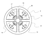
図6に、かご吊り滑車6における偶数個の動吸振器15の設置状態を示す。図6に示すように、かご吊り滑車6には、円周方向に等間隔に設けられた4個のスポーク13と、スポーク間で等間隔に4個の動吸振器15が配置されている。動吸振器15は、板状部材37で支持されたおもり18で構成されており、かご吊り滑車6のスポーク13間の空隙14内に設置され、一端が回転中心部11に固定され、滑車の回転方向に弾性を有して振動可能である。
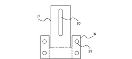
図7に、動吸振器15の構成を示す。図7(a)にかご吊り滑車6の側面からみた回転中心部11に固定されている動吸振器を示し、図7(b)にかご吊り滑車6の正面からみた動吸振器を示す。図7(a)に示すように、動吸振器15の板状部材37として、弾性を有する片持ち支持の板バネ17が用いられる。板バネ17の径方向に伸長する自由端側には、おもり18が取り付けられている。かご吊り滑車6の回転中心部11に、取付板16がボルト19で固定され、動吸振器15の板バネ17の固定端は、取付板16に固定されている。板バネ17には径方向に長穴20が設けられている。図7(b)に示すように、おもり18がボルト21とナット22によって、板バネ17の長穴20を通して固定されている。おもり18の径方向の位置は、長穴20の範囲内で調整することができる。
図7に、動吸振器15の構成を示す。図7(a)にかご吊り滑車6の側面からみた回転中心部11に固定されている動吸振器を示し、図7(b)にかご吊り滑車6の正面からみた動吸振器を示す。図7(a)に示すように、動吸振器15の板状部材37として、弾性を有する片持ち支持の板バネ17が用いられる。板バネ17の径方向に伸長する自由端側には、おもり18が取り付けられている。かご吊り滑車6の回転中心部11に、取付板16がボルト19で固定され、動吸振器15の板バネ17の固定端は、取付板16に固定されている。板バネ17には径方向に長穴20が設けられている。図7(b)に示すように、おもり18がボルト21とナット22によって、板バネ17の長穴20を通して固定されている。おもり18の径方向の位置は、長穴20の範囲内で調整することができる。
図8に、動吸振器15の板バネ17と取付板16の他の固定例を示す。板バネ17と取付板16の固定方法としては、溶接でも良いし、図8(a)に示すように、分割した取付板16で板バネ17を挟み込み、ボルト28とナット29で固定する方法でも良い。また、図8(b)に示すように、板バネ17をL字状に折り曲げて、ボルト30で取付板16に固定しても良い。
図9および図10に、弾性を有する板状部材を折り曲げることで板バネ17と取付板16を一体成形した動吸振器15の構成例を示す。板バネ17と取付板16を一体成形することで、従来の振り子構成の動吸振器に比べて、小型化できるとともに、部品点数も削減できる。
図9および図10に、弾性を有する板状部材を折り曲げることで板バネ17と取付板16を一体成形した動吸振器15の構成例を示す。板バネ17と取付板16を一体成形することで、従来の振り子構成の動吸振器に比べて、小型化できるとともに、部品点数も削減できる。
図9の動吸振器15の構成例では、取付板16部分の破線を山折り、一点鎖線を谷折りすることで、図7の構成例と同じ形状を実現できる。取付板16部分には複数のネジ穴23が設けられている。
図10の動吸振器15の構成例では、取付板16部分の破線を山折り、一点鎖線を谷折りする。回転中心部11との締結状態を図11に示す。取付板16部分には複数のネジ穴31が設けられている。図11の構成例では、取付板16を折り曲げて回転中心部11を挟み込んだ部分を、ボルト32とナット33で締結する。
図10の動吸振器15の構成例では、取付板16部分の破線を山折り、一点鎖線を谷折りする。回転中心部11との締結状態を図11に示す。取付板16部分には複数のネジ穴31が設けられている。図11の構成例では、取付板16を折り曲げて回転中心部11を挟み込んだ部分を、ボルト32とナット33で締結する。
なお、図9と図10に示す動吸振器15の構成例において、板バネ17には長穴20が設けられ、おもり18は板バネ17の長穴20を通してボルト21とナット22で固定されている。
このような動吸振器15の構成により、動吸振器15は滑車の空隙14内に設置することができ、かかる動吸振器15の作用によって、滑車の回転振動を抑制することができる。また、動吸振器15の取付板16は、滑車の回転中心部11に固定されるので、おもり18が、より外周部12側に設置されやすくなるため、おもり18で生じる回転慣性力が大きく働く結果、従来に比べて小さなおもり質量でも大きな制振効果が得られ、動吸振器15が小型化できる。さらに、板状部材37に用いられる板バネ17は、回転中心部11から径方向に長く設定できるので、長穴20も径方向に長くできるため、おもり18の位置を調整する調整幅も大きく設定することが可能となる。これにより、動吸振器の共振周波数の設定範囲を広く取ることができる。
このような動吸振器15の構成により、動吸振器15は滑車の空隙14内に設置することができ、かかる動吸振器15の作用によって、滑車の回転振動を抑制することができる。また、動吸振器15の取付板16は、滑車の回転中心部11に固定されるので、おもり18が、より外周部12側に設置されやすくなるため、おもり18で生じる回転慣性力が大きく働く結果、従来に比べて小さなおもり質量でも大きな制振効果が得られ、動吸振器15が小型化できる。さらに、板状部材37に用いられる板バネ17は、回転中心部11から径方向に長く設定できるので、長穴20も径方向に長くできるため、おもり18の位置を調整する調整幅も大きく設定することが可能となる。これにより、動吸振器の共振周波数の設定範囲を広く取ることができる。
図12は、エレベータ装置の滑車内における、共振周波数が異なる複数の動吸振器の設置状態を表す説明図である。図12に示す滑車内の動吸振器15の構成例では、1台の滑車内に4つの動吸振器15a、15b、15c、15dが配置されている。各動吸振器のおもり18の設置位置が異なっている。懸架手段4の経年変化による制振対象とする基準共振周波数の変化を予め想定して、おもり18の位置をそれぞれ異なるように調整された複数の動吸振器15a、15b、15c、15dを設置することで、予測される懸架手段4の経年変化による基準共振周波数の変化の影響を最小限に抑えることができる。
図12に示す滑車内の動吸振器15の構成例では、破線で示す円周が、制振対象とする基準共振周波数に対応するおもりの基準位置である。滑車の回転中心部に対して対称に配置された動吸振器15aと15cは、基準位置に対して、おもり18の位置を回転中心部寄り、すなわち、第1の距離38にずらしている。このため、動吸振器15aと15cの共振周波数は、制振対象とする回転系の共振周波数よりも高い値となる。一方、滑車の回転中心部に対して対称に配置された一組の動吸振器15bと15dは、基準位置に対して、おもり18の位置を外周部寄り、すなわち、第2の距離39にずらしている。このため、動吸振器15bと15dの共振周波数は、制振対象とする回転系の共振周波数よりも低い値となる。
図12に示す滑車内の動吸振器15の構成例では、破線で示す円周が、制振対象とする基準共振周波数に対応するおもりの基準位置である。滑車の回転中心部に対して対称に配置された動吸振器15aと15cは、基準位置に対して、おもり18の位置を回転中心部寄り、すなわち、第1の距離38にずらしている。このため、動吸振器15aと15cの共振周波数は、制振対象とする回転系の共振周波数よりも高い値となる。一方、滑車の回転中心部に対して対称に配置された一組の動吸振器15bと15dは、基準位置に対して、おもり18の位置を外周部寄り、すなわち、第2の距離39にずらしている。このため、動吸振器15bと15dの共振周波数は、制振対象とする回転系の共振周波数よりも低い値となる。
一端が回転中心部11に支持された板バネの他端におもりがある場合の動吸振器15の固有振動数f(単位:Hz)は、
 である。ここで,EI(Eはヤング率、Iは断面2次モーメント)は板バネ17の曲げ剛性を表し、Mはおもりの質量である。Lは板バネ17の支持点からおもり18までの距離であり、おもり18の設置位置を表す。式(1)により,制振対象とする基準共振周波数f0に対して,おもり18の設置位置L0は、
 である。懸架手段4の経年劣化により、基準共振周波数がf0から共振周波数f0+Δf(Δfは共振周波数の変化量)に変化すると、共振周波数の変化に対応するおもり18の設置位置L0+ΔL(ΔLはおもりの設置位置の移動量)は、
 である。よって,予め一台の滑車に複数の動吸振器15のおもり18の設置位置をL0からL0+ΔLの間で均等に配置すれば,懸架手段4の経年劣化に対して、動吸振器15を再調整する必要もなく,継続的に回転系の共振が抑制できる。
板バネ17に長穴20が設けられていて、長穴20に沿っておもり18の設置位置が容易に調整できるため、動吸振器15の共振周波数の設定と調整が容易である。1台の滑車内において、基準共振周波数よりも高い共振周波数の一組の動吸振器15を滑車の回転中心部に対して対称に配置すると共に、基準共振周波数よりも低い共振周波数の他の一組の動吸振器15を滑車の回転中心部に対して対称に配置することで、滑車の回転中心部に対して対称に配置するおもり18の設置位置を相対的に同じようにするため、おもり18の位置の違いによる慣性力で生じる滑車の偏荷重を防止できるとともに、一つの滑車内に設けられた共振周波数が異なる動吸振器15の組み合わせにより、懸架手段4の経年変化による基準共振周波数の変化にも対応した制振効果が得られる。
1台の滑車内において、滑車の回転中心部に対して対称に配置する2つの動吸振器15のおもりを回転中心部から同距離にずらした場合には、滑車の偏荷重は発生しない。滑車の回転中心部に対して対称に配置するおもり18の設置位置からずらした距離が同距離ではない場合は、おもり位置の違いによる滑車の偏荷重が発生する。この場合、図13に示すように、おもり位置の違いで発生する偏荷重を打ち消すため、調整質量36a、36bを滑車の外周部12に設けることにより、滑車に作用する偏荷重を完全に打ち消すことができる。
1台の滑車内において、滑車の回転中心部に対して対称に配置する2つの動吸振器15のおもりを回転中心部から同距離にずらした場合には、滑車の偏荷重は発生しない。滑車の回転中心部に対して対称に配置するおもり18の設置位置からずらした距離が同距離ではない場合は、おもり位置の違いによる滑車の偏荷重が発生する。この場合、図13に示すように、おもり位置の違いで発生する偏荷重を打ち消すため、調整質量36a、36bを滑車の外周部12に設けることにより、滑車に作用する偏荷重を完全に打ち消すことができる。
また、図14の滑車内の動吸振器の構成例に示すように、動吸振器15の板状部材37部分は板バネ17の代わりに、金属板を用い、弾性バネ35で支持された回転支点34を中心に回転する振り子式の構成に置き換えて、板状部材37におけるおもり18の設置位置を変更することにより、同様に一台の滑車に共振周波数の異なる動吸振器を設置できる。
以上、実施の形態1のエレベータ装置における滑車内の動吸振器によれば、エレベータ装置の各滑車において、それぞれの制振対象とする基準共振周波数に対応する動吸振器15を設置できる。さらに、滑車に偏荷重が作用することなく、動吸振器15のおもりの設置位置が調整可能であるため、一台の滑車に共振周波数の異なる動吸振器を予め設置することにより、制振対象とする基準共振周波数の経年変化に対応して制振性能を保つエレベータ装置が得られる。
実施の形態2.
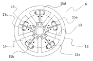
図15に本発明の実施の形態2のエレベータ装置における滑車内にスポーク数が奇数で、奇数個の動吸振器15が取り付けられる構成例を示す。図15においては、かご吊り滑車6の円周方向に等間隔に設けられた5個のスポーク13とスポーク間で等間隔に配置された5個の動吸振器15を有する。
なお、実施の形態2以降の各実施の形態に係るエレベータ装置の回転モードの構成およびエレベータ装置における複数の滑車内の動吸振器15の設置態様は、実施の形態1に係るエレベータ装置と同一であるため、説明を省略する。
図15に本発明の実施の形態2のエレベータ装置における滑車内にスポーク数が奇数で、奇数個の動吸振器15が取り付けられる構成例を示す。図15においては、かご吊り滑車6の円周方向に等間隔に設けられた5個のスポーク13とスポーク間で等間隔に配置された5個の動吸振器15を有する。
なお、実施の形態2以降の各実施の形態に係るエレベータ装置の回転モードの構成およびエレベータ装置における複数の滑車内の動吸振器15の設置態様は、実施の形態1に係るエレベータ装置と同一であるため、説明を省略する。
図12および図13の滑車内の動吸振器の構成例は、滑車のスポークの数が偶数の場合であり、この場合、動吸振器を滑車の回転中心部に対して対称に配置することができる。一方、スポークの数が奇数の場合、例えば、図15に示すスポークの数が5本の場合は、各スポーク間に等間隔に動吸振器15a、15b、15c、15d、15eが設置されている。一つの動吸振器15dのおもり18が、破線円周で示す基準位置L0から外周部側へL0+ΔLのところに設置される場合に、滑車の回転中心部に対して対向する位置に隣接する動吸振器15a、15bのおもり18も外周部側よりに設置される。一方、動吸振器15dの両側に隣接する動吸振器15c、15eは、滑車に偏荷重が作用しないように、おもり18を回転中心部側寄りに設置する。
各動吸振器のおもり18の設置位置については、具体的には、動吸振器15dのおもりの設置位置がL0+ΔLに設定された場合は、動吸振器15a、15bのおもりの設置位置を、L0、動吸振器15c、15eのおもりの設置位置を、L0-(1/2)×ΔLとする。
各動吸振器のおもり18の設置位置については、具体的には、動吸振器15dのおもりの設置位置がL0+ΔLに設定された場合は、動吸振器15a、15bのおもりの設置位置を、L0、動吸振器15c、15eのおもりの設置位置を、L0-(1/2)×ΔLとする。
これらの設置半径により、おもり位置の違いによる滑車の偏荷重を打ち消すことともに、各動吸振器の共振周波数を異なるように設定可能となる。なお、上記の設定でも,滑車に作用する偏荷重を完全に打ち消すことは困難である。完全に偏荷重を打ち消すために、図16の滑車内の動吸振器の構成例に示すように調整質量36a、36b、36c、36d、36eを滑車の外周部12に取り付けても良い。
このように、滑車のスポークの数が奇数の場合であっても、複数の動吸振器で、共振周波数が異なるように設置しつつ、動吸振器15のおもりによる慣性力によって生じる滑車の偏荷重を抑制することができる。
また、図14の滑車内の動吸振器の構成例に示すように、動吸振器15の板状部材37部分は板バネ17の代わりに、金属板を用い、弾性バネ35で支持された回転支点34を中心に回転する振り子式の構成に置き換えても良い。
また、図14の滑車内の動吸振器の構成例に示すように、動吸振器15の板状部材37部分は板バネ17の代わりに、金属板を用い、弾性バネ35で支持された回転支点34を中心に回転する振り子式の構成に置き換えても良い。
以上、実施の形態2のエレベータ装置における滑車内の動吸振器によれば、一台の滑車内に奇数の動吸振器を設置しても、滑車に偏荷重が作用することなく、動吸振器15のおもりの設置位置が調整可能であるため、一台の滑車に共振周波数の異なる動吸振器を予め設置することにより、制振対象とする基準共振周波数の経年変化に対応して制振性能を保つエレベータ装置が得られる。
実施の形態3.
図17に本発明の実施の形態3のエレベータ装置に用いられる動吸振器15の構成を示し、図18に滑車内の動吸振器15の設置状態を示す。実施の形態1と2では、おもり18の設置位置を調整することによって、動吸振器15の共振周波数を設定しているが、実施の形態3では、おもり18の質量を変更することにより共振周波数を設定する。
図17において、動吸振器15の板バネ17に長穴20は設けられておらず、板バネ17の特定の位置、すなわち回転中心部から同一距離におもり18が固定される。図17に示すように、おもり18には質量調整用の調整おもり24が複数配置される。調整おもり24の数(または質量)を変更することにより、所望の共振周波数に設定することができる。
図17に本発明の実施の形態3のエレベータ装置に用いられる動吸振器15の構成を示し、図18に滑車内の動吸振器15の設置状態を示す。実施の形態1と2では、おもり18の設置位置を調整することによって、動吸振器15の共振周波数を設定しているが、実施の形態3では、おもり18の質量を変更することにより共振周波数を設定する。
図17において、動吸振器15の板バネ17に長穴20は設けられておらず、板バネ17の特定の位置、すなわち回転中心部から同一距離におもり18が固定される。図17に示すように、おもり18には質量調整用の調整おもり24が複数配置される。調整おもり24の数(または質量)を変更することにより、所望の共振周波数に設定することができる。
懸架手段4の経年変化による制振対象とする基準共振周波数の変化に対して、調整おもり24の数(または質量)が変更できる複数の動吸振器15a、15b、15c、15dを適用することにより、対応可能となる。調整おもり24の数(または質量)を減らすことで、基準の共振周波数より高い周波数に設定される一組の動吸振器15b、15dを滑車の回転中心部に対して対称に配置すると共に、調整おもり24の数(または質量)を増やすことで、基準の共振周波数より低い周波数に設定される他の一組の動吸振器15a、15cを滑車の回転中心部に対して対称に配置する。動吸振器15a、15cはおもりの質量が同一であり、動吸振器15b、15dはおもりの質量が同一であり、かつ、動吸振器15a、15cと動吸振器15b、15dのおもりの質量とも異なる。
すなわち、実施の形態1と同様に、1台の滑車内において、基準共振周波数よりも高い共振周波数の一組の動吸振器15を滑車の回転中心部に対して対称に配置すると共に、基準共振周波数よりも低い共振周波数の他の一組の動吸振器15を滑車の回転中心部に対して対称に配置することで、滑車の回転中心部に対して対称に配置するおもり18の質量を相対的に同じように設定するため、おもり質量の違いによる慣性力で生じる滑車の偏荷重を防止できるとともに、共振周波数が異なる動吸振器15の組み合わせにより、懸架手段4の経年変化による基準共振周波数の変化にも対応した制振効果が得られる。
すなわち、実施の形態1と同様に、1台の滑車内において、基準共振周波数よりも高い共振周波数の一組の動吸振器15を滑車の回転中心部に対して対称に配置すると共に、基準共振周波数よりも低い共振周波数の他の一組の動吸振器15を滑車の回転中心部に対して対称に配置することで、滑車の回転中心部に対して対称に配置するおもり18の質量を相対的に同じように設定するため、おもり質量の違いによる慣性力で生じる滑車の偏荷重を防止できるとともに、共振周波数が異なる動吸振器15の組み合わせにより、懸架手段4の経年変化による基準共振周波数の変化にも対応した制振効果が得られる。
一方、上記の構成例では、スポークの数が偶数の例を説明したが、実施の形態2と同様に、スポークの数が奇数で奇数の動吸振器の場合においても、それぞれのおもりの質量調整を行い、滑車に偏荷重が作用しないように共振周波数の異なる動吸振器の組み合わせを設置できる。
また、実施の形態3でも、図14に示すように、動吸振器15の板状部材37部分は板バネ17の代わりに、金属板を用い、弾性バネ35で支持された回転支点34を中心に回転する振り子式の構成に置き換えても良い。
また、実施の形態3でも、図14に示すように、動吸振器15の板状部材37部分は板バネ17の代わりに、金属板を用い、弾性バネ35で支持された回転支点34を中心に回転する振り子式の構成に置き換えても良い。
以上、実施の形態3のエレベータ装置における滑車内の動吸振器によれば、滑車に偏荷重が作用することなく、一台の滑車に共振周波数の異なる動吸振器を予め設置することにより、制振対象とする基準共振周波数の経年変化に対応して制振性能を保つエレベータ装置が得られる。
実施の形態4.
図19に本発明の実施の形態4のエレベータ装置における滑車内の動吸振器の設置状態を示す。実施の形態4では、動吸振器15の板バネ17の板厚を変更することにより、動吸振器15の共振周波数の変動量が大きく調整できる。かつ、おもり18の設置位置を微調整することにより、動吸振器15の共振周波数を所定の値に設定できる。実施の形態4では、動吸振器15の板バネ17には長穴20が設けられており、おもり18の設置位置を調整可能となっている。
図19において、かご吊り滑車6には、懸架手段4の経年変化によって、生じると予測される制振対象とする基準共振周波数の変化に対して、板バネ17の板厚を変更した複数の動吸振器15a、15b、15c、15dを設置することにより、広い範囲の共振周波数の変動に対応できる。なお、最終的な周波数設定は、おもり18の位置の微調整によって実施する。実施の形態4では、おもり18の設置位置の調整量を少なくすることができるため、動吸振器により滑車に作用する慣性力の影響も小さい。
図19に本発明の実施の形態4のエレベータ装置における滑車内の動吸振器の設置状態を示す。実施の形態4では、動吸振器15の板バネ17の板厚を変更することにより、動吸振器15の共振周波数の変動量が大きく調整できる。かつ、おもり18の設置位置を微調整することにより、動吸振器15の共振周波数を所定の値に設定できる。実施の形態4では、動吸振器15の板バネ17には長穴20が設けられており、おもり18の設置位置を調整可能となっている。
図19において、かご吊り滑車6には、懸架手段4の経年変化によって、生じると予測される制振対象とする基準共振周波数の変化に対して、板バネ17の板厚を変更した複数の動吸振器15a、15b、15c、15dを設置することにより、広い範囲の共振周波数の変動に対応できる。なお、最終的な周波数設定は、おもり18の位置の微調整によって実施する。実施の形態4では、おもり18の設置位置の調整量を少なくすることができるため、動吸振器により滑車に作用する慣性力の影響も小さい。
おもり18の設置位置の調整については、実施の形態1と同様に、おもり18を回転中心部側に設置した一組の動吸振器15a、15cを滑車の回転中心部に対して対称に配置すると共に、おもり18を外周部側に設置した他の一組の動吸振器15b、15dを滑車の回転中心部に対して対称に配置する。これにより、おもり18の設置位置による滑車への偏荷重を防止できる。
また、おもり18の設置位置の調整の代わりに、実施の形態3と同様に、おもり18の質量を調整しても同様の効果が得られる。
また、おもり18の設置位置の調整の代わりに、実施の形態3と同様に、おもり18の質量を調整しても同様の効果が得られる。
以上、実施の形態4のエレベータ装置における滑車内の動吸振器によれば、滑車に偏荷重が作用することなく、一台の滑車に共振周波数の異なる動吸振器を予め設置することにより、予測される制振対象とする基準共振周波数の経年変化に対応して制振性能を保つエレベータ装置が得られる。
実施の形態5.
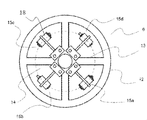
図20は、本発明の実施の形態5のエレベータ装置における滑車内の動吸振器の設置状態を表す説明図である。実施の形態5では、実施の形態4と同様に、動吸振器15の板バネ17の板厚を変更することにより、動吸振器15の共振周波数の変動量を調整している。また、板バネ17に長穴は設置されておらず、特定の位置におもり18が固定される。経年変化による制振対象とする基準共振周波数の変化に対しては、板バネ17の板厚を変更した複数の動吸振器15a、15b、15c、15dを設置することで対応可能となる。
図20に示すように、滑車に動吸振器15a、15b、15c、15dのおもり18の設置位置を破線で示す滑車の回転中心部から同一距離上に配置し、かつ、全てのおもり18を同質量にしている。これにより、動吸振器により滑車に作用する慣性力が完全に打ち消され、滑車に偏荷重が作用することはない。なお、板バネ17の厚み差による質量差はおもりに比べて微量であるため、滑車に作用する偏荷重の影響は考慮しなくて良い。
図20は、本発明の実施の形態5のエレベータ装置における滑車内の動吸振器の設置状態を表す説明図である。実施の形態5では、実施の形態4と同様に、動吸振器15の板バネ17の板厚を変更することにより、動吸振器15の共振周波数の変動量を調整している。また、板バネ17に長穴は設置されておらず、特定の位置におもり18が固定される。経年変化による制振対象とする基準共振周波数の変化に対しては、板バネ17の板厚を変更した複数の動吸振器15a、15b、15c、15dを設置することで対応可能となる。
図20に示すように、滑車に動吸振器15a、15b、15c、15dのおもり18の設置位置を破線で示す滑車の回転中心部から同一距離上に配置し、かつ、全てのおもり18を同質量にしている。これにより、動吸振器により滑車に作用する慣性力が完全に打ち消され、滑車に偏荷重が作用することはない。なお、板バネ17の厚み差による質量差はおもりに比べて微量であるため、滑車に作用する偏荷重の影響は考慮しなくて良い。
したがって、実施の形態4の場合とは異なり、板厚のより厚い、またはより薄い板バネを有する動吸振器同士を必ずしも滑車の回転中心部に対して対称に配置する必要はなく、互いに隣接させて配置しても良い。例えば、図20に示す動吸振器の配置のように、動吸振器15aと15bの板バネの板厚がより厚く(太線で表示される17aと17b)、動吸振器15cと15dの板バネの板厚がより薄い(細線で表示される17cと17d)ような態様でも許容される。
以上、実施の形態5のエレベータ装置における滑車内の動吸振器では、おもりの設置位置の変動で生じる滑車の偏荷重を配慮せずに動吸振器を任意の位置に配置できるため、動吸振器の設置手段を簡素化することができる。同様に、滑車に偏荷重が作用することなく、一台の滑車に共振周波数の異なる動吸振器を予め設置することにより、予測される制振対象とする基準共振周波数の経年変化に対応して制振性能を保つエレベータ装置が得られる。
実施の形態6.
図21は、本発明の実施の形態6のエレベータ装置における滑車内の動吸振器の設置状態を表す説明図である。動吸振器は、上述の図14と同様に、弾性バネ35で支持された回転支点34を中心に回転する振り子式の構成となっている。
実施の形態5と同様に、実施の形態6では、滑車に動吸振器15a、15b、15c、15dのおもり18の設置位置を破線で示す滑車の回転中心部から同一距離に配置し、全てのおもり18を同質量にしている。
図21は、本発明の実施の形態6のエレベータ装置における滑車内の動吸振器の設置状態を表す説明図である。動吸振器は、上述の図14と同様に、弾性バネ35で支持された回転支点34を中心に回転する振り子式の構成となっている。
実施の形態5と同様に、実施の形態6では、滑車に動吸振器15a、15b、15c、15dのおもり18の設置位置を破線で示す滑車の回転中心部から同一距離に配置し、全てのおもり18を同質量にしている。
一方、実施の形態5では、動吸振器の板バネ17の板厚を変更することにより、動吸振器15の共振周波数の変動量を調整しているが、実施の形態6では、動吸振器に取り付ける弾性バネ35の剛性の強さを変えることにより、動吸振器15の共振周波数を変更している。
すなわち、図21において、滑車の回転中心部に対して対称に配置する一組の動吸振器15b、15dに取り付ける弾性バネ35b、35dをより強いバネ定数のものとするのに対して、他の一組の動吸振器15a、15cに取り付ける弾性バネ35a、35cを相対的に弱いバネ定数のものとする。
また、全てのおもり18を滑車の回転中心部から同一距離に配置しているため、動吸振器により滑車に作用する慣性力を完全に打ち消し、滑車に偏荷重が作用することはない。したがって、弾性バネの剛性がより強い、またはより弱い動吸振器同士が必ずしも滑車の回転中心部に対して対称に配置する必要はなく、隣接に配置しても良い。
すなわち、図21において、滑車の回転中心部に対して対称に配置する一組の動吸振器15b、15dに取り付ける弾性バネ35b、35dをより強いバネ定数のものとするのに対して、他の一組の動吸振器15a、15cに取り付ける弾性バネ35a、35cを相対的に弱いバネ定数のものとする。
また、全てのおもり18を滑車の回転中心部から同一距離に配置しているため、動吸振器により滑車に作用する慣性力を完全に打ち消し、滑車に偏荷重が作用することはない。したがって、弾性バネの剛性がより強い、またはより弱い動吸振器同士が必ずしも滑車の回転中心部に対して対称に配置する必要はなく、隣接に配置しても良い。
以上、実施の形態6のエレベータ装置における滑車内の動吸振器では、おもりの設置位置の変動で生じる滑車の偏荷重を配慮せずに動吸振器を配置することができるため、動吸振器の設置手段を簡素化することができる。同様に、滑車に偏荷重が作用することなく、一台の滑車に共振周波数の異なる動吸振器を予め設置することにより、予測される制振対象とする基準共振周波数の経年変化に対応して制振性能を保つエレベータ装置が得られる。
実施の形態7.
図22は、本発明の実施の形態7のエレベータ装置における滑車内の動吸振器の設置状態を表す説明図である。実施の形態7では、図21に示す実施の形態6と同様に、動吸振器が回転支点34を中心に回転する振り子式の構成となっている。また、図21に示す実施の形態6と同様に、動吸振器15a、15b、15c、15dのおもり位置を破線で示す滑車の回転中心部から同一距離に配置し、全てのおもり18を同質量にしている。
一方、実施の形態6とは異なり、実施の形態7では、バネ35は全て同じバネ定数とし、回転支点34に対してバネ35を径方向に離れた位置に変えることにより、動吸振器15の共振周波数を変更している。
すなわち、図22において、動吸振器15a、15cのバネの固定位置をより外周部側に、動吸振器15b、15dのバネの固定位置をより回転中心部側に配置している。
また、全てのおもり18が滑車の回転中心部から同一距離に配置されているため、動吸振器により滑車に作用する慣性力が完全に打ち消され、滑車に偏荷重が作用することはない。
図22は、本発明の実施の形態7のエレベータ装置における滑車内の動吸振器の設置状態を表す説明図である。実施の形態7では、図21に示す実施の形態6と同様に、動吸振器が回転支点34を中心に回転する振り子式の構成となっている。また、図21に示す実施の形態6と同様に、動吸振器15a、15b、15c、15dのおもり位置を破線で示す滑車の回転中心部から同一距離に配置し、全てのおもり18を同質量にしている。
一方、実施の形態6とは異なり、実施の形態7では、バネ35は全て同じバネ定数とし、回転支点34に対してバネ35を径方向に離れた位置に変えることにより、動吸振器15の共振周波数を変更している。
すなわち、図22において、動吸振器15a、15cのバネの固定位置をより外周部側に、動吸振器15b、15dのバネの固定位置をより回転中心部側に配置している。
また、全てのおもり18が滑車の回転中心部から同一距離に配置されているため、動吸振器により滑車に作用する慣性力が完全に打ち消され、滑車に偏荷重が作用することはない。
以上、実施の形態7のエレベータ装置における滑車内の動吸振器では、おもりの設置位置の変動で生じる滑車の偏荷重を配慮せずに動吸振器を配置することができるため、動吸振器の設置手段を簡素化することができる。同様に、滑車に偏荷重が作用することなく、一台の滑車に共振周波数の異なる動吸振器を予め設置することにより、予測される制振対象とする基準共振周波数の経年変化に対応して制振性能を保つエレベータ装置が得られる。
実施の形態8.
図23は、本発明の実施の形態8のエレベータ装置における滑車内の動吸振器の設置状態を表す説明図である。実施の形態8では、滑車の中心部における動吸振器15の取り付け態様が、ほかの実施の形態とは異なる。滑車の回転中心部11に動吸振器15を取り付けるスペースが限られるため、設置が困難となる場合があり得る。この場合、回転中心部11に板バネ17の一端を固定する代わりに、スポーク13の回転中心部側の部位に取付板25を設置し、取付板25を介して板バネ17の一端を固定する。板バネ17は外周部方向に伸長する自由端をなし、滑車の回転方向に弾性を有する。板バネ17の固定端から自由端に至るいずれかの位置におもりが固定され、滑車の回転方向に振動できる。
図23は、本発明の実施の形態8のエレベータ装置における滑車内の動吸振器の設置状態を表す説明図である。実施の形態8では、滑車の中心部における動吸振器15の取り付け態様が、ほかの実施の形態とは異なる。滑車の回転中心部11に動吸振器15を取り付けるスペースが限られるため、設置が困難となる場合があり得る。この場合、回転中心部11に板バネ17の一端を固定する代わりに、スポーク13の回転中心部側の部位に取付板25を設置し、取付板25を介して板バネ17の一端を固定する。板バネ17は外周部方向に伸長する自由端をなし、滑車の回転方向に弾性を有する。板バネ17の固定端から自由端に至るいずれかの位置におもりが固定され、滑車の回転方向に振動できる。
以上、実施の形態8のエレベータ装置における滑車内の動吸振器によっても、限られた滑車の回転中心部11のスペースに影響を受けずに、動吸振器を設置することができる。同様に、滑車に偏荷重が作用することなく、一台の滑車に共振周波数の異なる動吸振器を予め設置することにより、予測される制振対象とする基準共振周波数の経年変化に対応して制振性能を保つエレベータ装置が得られる。
1 昇降路、2 かご、3 釣合おもり、4 懸架手段、5 綱車、6 かご吊り滑車、7 かご吊り滑車、8 釣合おもり吊り滑車、9 かご側綱止め、10 釣合おもり側綱止め、11 回転中心部、12 外周部、13 スポーク、14 空隙、15 動吸振器、16 取付板、17 板バネ、18 おもり、19 ボルト、20 長穴、21 ボルト、22 ナット、23 ネジ穴、24 調整おもり、25 取付板、26 かご返し滑車、27 釣合おもり返し滑車、28 ボルト、29 ナット、30 ボルト、31 ネジ穴、32 ボルト、33 ナット、34 回転支点、35 バネ、36 調整質量、37 板状部材、38 第1の距離、39 第2の距離
Claims (14)
- 昇降路内を昇降するかごと、
前記昇降路内に配置され、前記かごと連動して昇降する釣合おもりと、
前記かごと前記釣合おもりとを吊り下げる懸架手段と、
前記懸架手段が巻掛けられ、回転中心部と、前記回転中心部から径方向に伸長する複数のスポークと、前記スポークによって支持される外周部と、をそれぞれ有する、前記かごに搭載されるかご吊り滑車、および、前記釣合おもりに搭載される釣合おもり吊り滑車と、
前記かご吊り滑車と前記釣合おもり吊り滑車の少なくとも一つの滑車における前記スポーク間に配置され、一端が前記滑車の回転中心部に固定される固定端をなし、他端が径方向に伸長する自由端をなし前記滑車の回転方向に弾性を有する板状部材からなり、前記板状部材の固定端から自由端に至るいずれかの位置におもりが固定され、前記滑車の回転方向に振動可能な動吸振器と、
を備えるエレベータ装置。 - 前記動吸振器の前記板状部材は、片持ち支持の板バネが用いられることを特徴とする請求項1に記載のエレベータ装置。
- 前記板バネは、前記滑車の回転中心部に取り付ける取付板と一体であることを特徴とする請求項2に記載のエレベータ装置。
- 前記動吸振器は、前記板状部材の固定端の円周方向に沿った両側に弾性バネが取り付けられることを特徴とする請求項1に記載のエレベータ装置。
- 前記滑車のうち少なくとも一つが円周方向に等間隔に設けられた偶数個の前記スポークと前記スポーク間で等間隔に配置された前記動吸振器を有し、前記複数の動吸振器のうち前記回転中心部に対して対称に配置された一組の前記動吸振器の共振周波数が前記滑車の基準共振周波数に対して増加するように調整され、他の一組の前記動吸振器の共振周波数が前記基準共振周波数に対して減少するように調整されたことを特徴とする請求項1から4のいずれか1項に記載のエレベータ装置。
- 前記滑車のうち少なくとも一つが円周方向に等間隔に設けられた5以上で奇数個の前記スポークと前記スポーク間で等間隔に配置された前記動吸振器を有し、前記複数の動吸振器のうち、一つの前記動吸振器の共振周波数が前記滑車の基準共振周波数に対して増加、前記一つの前記動吸振器の円周方向の両側に隣接する2つの前記動吸振器からなる一組の前記動吸振器の共振周波数が前記基準共振周波数に対して減少、前記一つの前記動吸振器が前記回転中心部に対して対向する位置に隣接する他の2つの前記動吸振器からなる他の一組の動吸振器の共振周波数が前記基準共振周波数に対して増加するようにそれぞれ調整されたことを特徴とする請求項1から4のいずれか1項に記載のエレベータ装置。
- 前記一組の動吸振器のおもりが前記回転中心部からそれぞれ第1の距離に設置され、前記他の一組の動吸振器のおもりが前記回転中心部からそれぞれ第2の距離に設置され、前記第1の距離と前記第2の距離は異なることを特徴とする請求項5に記載のエレベータ装置。
- 前記スポーク数が5個である前記滑車における、前記スポーク間に配置される5つの前記動吸振器のうち一つの前記動吸振器の前記おもりの設置位置を、前記基準共振周波数に対する前記おもりの設置位置をL0、前記L0に対する移動量をΔLとした場合に、
前記回転中心部からL0+ΔLとし、かつ、
前記一つの前記動吸振器に隣接する2つの前記動吸振器の前記おもりの設置を前記回転中心部からL0-(1/2)×ΔLとし、
前記一つの前記動吸振器と前記回転中心部に対して対向する位置に隣接する他の2つの前記動吸振器の前記おもりの前記設置位置は前記回転中心部からL0とすることを特徴とする請求項6に記載のエレベータ装置。 - 前記滑車の外周部側に調整質量を配置することにより、滑車の偏荷重を打ち消すことを特徴とする請求項1から8のいずれか1項に記載のエレベータ装置。
- 前記滑車における複数の前記動吸振器の前記おもりが前記回転中心部から同一距離に配置され、前記一組の動吸振器のおもりの質量が同一であり、前記他の一組の動吸振器のおもりの質量が同一で、かつ、前記一組の動吸振器のおもりの質量とは異なることを特徴とする請求項5に記載のエレベータ装置。
- 前記板バネの板厚が互いに異なる動吸振器が含まれること特徴とする請求項2に記載のエレベータ装置。
- 前記弾性バネの剛性が互いに異なる動吸振器が含まれること特徴とする請求項4に記載のエレベータ装置。
- 前記滑車における複数の前記動吸振器の前記弾性バネが前記回転中心部からの固定位置を異ならせることを特徴とする請求項4に記載のエレベータ装置。
- 昇降路内を昇降するかごと、
前記昇降路内に配置され、前記かごと連動して昇降する釣合おもりと、
前記かごと前記釣合おもりとを吊り下げる懸架手段と、
前記懸架手段を巻掛け、回転中心部と、前記回転中心部から径方向に伸長する複数のスポークと、前記スポークによって支持される外周部と、をそれぞれ有する、前記かごに搭載されるかご吊り滑車、および、前記釣合おもりに搭載される釣合おもり吊り滑車と、
前記かご吊り滑車と前記釣合おもり吊り滑車の少なくとも一つの滑車における前記スポーク間に配置され、一端が前記スポークの前記回転中心部側の部位に取り付けられる固定端をなし、他端が前記外周部方向に伸長する自由端をなし前記滑車の回転方向に弾性を有する板状部材からなり、前記板状部材の固定端から自由端に至るいずれかの位置におもりが固定され、前記滑車の回転方向に振動可能な動吸振器と、
を備えるエレベータ装置。
Priority Applications (2)
| Application Number | Priority Date | Filing Date | Title |
|---|---|---|---|
| JP2019501736A JP6525369B1 (ja) | 2018-07-26 | 2018-07-26 | エレベータ装置 |
| PCT/JP2018/028056 WO2020021671A1 (ja) | 2018-07-26 | 2018-07-26 | エレベータ装置 |
Applications Claiming Priority (1)
| Application Number | Priority Date | Filing Date | Title |
|---|---|---|---|
| PCT/JP2018/028056 WO2020021671A1 (ja) | 2018-07-26 | 2018-07-26 | エレベータ装置 |
Publications (1)
| Publication Number | Publication Date |
|---|---|
| WO2020021671A1 true WO2020021671A1 (ja) | 2020-01-30 |
Family
ID=66730621
Family Applications (1)
| Application Number | Title | Priority Date | Filing Date |
|---|---|---|---|
| PCT/JP2018/028056 Ceased WO2020021671A1 (ja) | 2018-07-26 | 2018-07-26 | エレベータ装置 |
Country Status (2)
| Country | Link |
|---|---|
| JP (1) | JP6525369B1 (ja) |
| WO (1) | WO2020021671A1 (ja) |
Cited By (1)
| Publication number | Priority date | Publication date | Assignee | Title |
|---|---|---|---|---|
| CN112591585A (zh) * | 2020-11-24 | 2021-04-02 | 日立电梯(中国)有限公司 | 一种直角开门轿底架配重安装结构 |
Citations (6)
| Publication number | Priority date | Publication date | Assignee | Title |
|---|---|---|---|---|
| JPS61149635A (ja) * | 1984-12-21 | 1986-07-08 | Hitachi Ltd | 内燃機関用クランクプ−リ |
| JPS6421894U (ja) * | 1987-07-31 | 1989-02-03 | ||
| JPH07190146A (ja) * | 1993-11-26 | 1995-07-28 | Carl Freudenberg:Fa | ねじり振動止め |
| JP2001041291A (ja) * | 1999-07-26 | 2001-02-13 | Honda Motor Co Ltd | バランスウェイト取り付け構造及び取り付け方法 |
| JP2001280412A (ja) * | 2000-03-31 | 2001-10-10 | Mitsubishi Electric Corp | 回転体の動吸振装置及び同装置を用いたエレベータ |
| JP2013107755A (ja) * | 2011-11-22 | 2013-06-06 | Mitsubishi Electric Corp | エレベータ装置 |
-
2018
- 2018-07-26 JP JP2019501736A patent/JP6525369B1/ja not_active Expired - Fee Related
- 2018-07-26 WO PCT/JP2018/028056 patent/WO2020021671A1/ja not_active Ceased
Patent Citations (6)
| Publication number | Priority date | Publication date | Assignee | Title |
|---|---|---|---|---|
| JPS61149635A (ja) * | 1984-12-21 | 1986-07-08 | Hitachi Ltd | 内燃機関用クランクプ−リ |
| JPS6421894U (ja) * | 1987-07-31 | 1989-02-03 | ||
| JPH07190146A (ja) * | 1993-11-26 | 1995-07-28 | Carl Freudenberg:Fa | ねじり振動止め |
| JP2001041291A (ja) * | 1999-07-26 | 2001-02-13 | Honda Motor Co Ltd | バランスウェイト取り付け構造及び取り付け方法 |
| JP2001280412A (ja) * | 2000-03-31 | 2001-10-10 | Mitsubishi Electric Corp | 回転体の動吸振装置及び同装置を用いたエレベータ |
| JP2013107755A (ja) * | 2011-11-22 | 2013-06-06 | Mitsubishi Electric Corp | エレベータ装置 |
Cited By (1)
| Publication number | Priority date | Publication date | Assignee | Title |
|---|---|---|---|---|
| CN112591585A (zh) * | 2020-11-24 | 2021-04-02 | 日立电梯(中国)有限公司 | 一种直角开门轿底架配重安装结构 |
Also Published As
| Publication number | Publication date |
|---|---|
| JPWO2020021671A1 (ja) | 2020-08-06 |
| JP6525369B1 (ja) | 2019-06-05 |
Similar Documents
| Publication | Publication Date | Title |
|---|---|---|
| KR101835237B1 (ko) | 현수식 엘리베이터 | |
| JP2013095570A (ja) | 制振装置を備えたエレベーター | |
| JP3428042B2 (ja) | エレベータの振動防止装置 | |
| JP5636193B2 (ja) | ダブルデッキエレベーター | |
| JP2000086123A (ja) | エレベータ装置 | |
| JP6215093B2 (ja) | エレベーター及びそれに用いるコンペンプーリ | |
| JP6525369B1 (ja) | エレベータ装置 | |
| CN107021406B (zh) | 电梯装置 | |
| JP6416037B2 (ja) | エレベーター | |
| KR20060040577A (ko) | 엘리베이터용 균형 조절 기구 | |
| JP5285583B2 (ja) | エレベータ乗りかご用縦振動抑制装置 | |
| EP1604937B1 (en) | Elevator rope holding structure | |
| JP2760676B2 (ja) | 高速エレベータ | |
| JPWO2006021996A1 (ja) | エレベータ装置 | |
| JP2001247263A (ja) | エレベータの振動抑制装置 | |
| JP2001280412A (ja) | 回転体の動吸振装置及び同装置を用いたエレベータ | |
| JP6767680B2 (ja) | エレベータ用釣合い錘及びそれを備えるエレベータ | |
| CN119816464A (zh) | 用于双层电梯的行驶篮结构 | |
| JPH04144891A (ja) | エレベータ | |
| JP2003221177A (ja) | エレベーターの巻上機装置 | |
| WO2013088507A1 (ja) | アクティブ動減衰器およびエレベータの振動制御方法 | |
| EP4389673A1 (en) | Elevator car and elevator | |
| JPWO2005080250A1 (ja) | 機械室レスエレベータ | |
| JP2025070443A (ja) | エレベーター | |
| HK40119146A (zh) | 用於双层电梯的行驶篮结构 |
Legal Events
| Date | Code | Title | Description |
|---|---|---|---|
| ENP | Entry into the national phase |
Ref document number: 2019501736 Country of ref document: JP Kind code of ref document: A |
|
| 121 | Ep: the epo has been informed by wipo that ep was designated in this application |
Ref document number: 18927548 Country of ref document: EP Kind code of ref document: A1 |
|
| NENP | Non-entry into the national phase |
Ref country code: DE |
|
| 122 | Ep: pct application non-entry in european phase |
Ref document number: 18927548 Country of ref document: EP Kind code of ref document: A1 |