WO2020009006A1 - 内燃機関の可変動弁システム及びその制御装置 - Google Patents
内燃機関の可変動弁システム及びその制御装置 Download PDFInfo
- Publication number
- WO2020009006A1 WO2020009006A1 PCT/JP2019/025723 JP2019025723W WO2020009006A1 WO 2020009006 A1 WO2020009006 A1 WO 2020009006A1 JP 2019025723 W JP2019025723 W JP 2019025723W WO 2020009006 A1 WO2020009006 A1 WO 2020009006A1
- Authority
- WO
- WIPO (PCT)
- Prior art keywords
- intake
- exhaust
- valve
- variable valve
- load region
- Prior art date
- Legal status (The legal status is an assumption and is not a legal conclusion. Google has not performed a legal analysis and makes no representation as to the accuracy of the status listed.)
- Ceased
Links
Images




Classifications
-
- F—MECHANICAL ENGINEERING; LIGHTING; HEATING; WEAPONS; BLASTING
- F02—COMBUSTION ENGINES; HOT-GAS OR COMBUSTION-PRODUCT ENGINE PLANTS
- F02D—CONTROLLING COMBUSTION ENGINES
- F02D13/00—Controlling the engine output power by varying inlet or exhaust valve operating characteristics, e.g. timing
- F02D13/02—Controlling the engine output power by varying inlet or exhaust valve operating characteristics, e.g. timing during engine operation
-
- F—MECHANICAL ENGINEERING; LIGHTING; HEATING; WEAPONS; BLASTING
- F02—COMBUSTION ENGINES; HOT-GAS OR COMBUSTION-PRODUCT ENGINE PLANTS
- F02M—SUPPLYING COMBUSTION ENGINES IN GENERAL WITH COMBUSTIBLE MIXTURES OR CONSTITUENTS THEREOF
- F02M26/00—Engine-pertinent apparatus for adding exhaust gases to combustion-air, main fuel or fuel-air mixture, e.g. by exhaust gas recirculation [EGR] systems
- F02M26/01—Internal exhaust gas recirculation, i.e. wherein the residual exhaust gases are trapped in the cylinder or pushed back from the intake or the exhaust manifold into the combustion chamber without the use of additional passages
-
- Y—GENERAL TAGGING OF NEW TECHNOLOGICAL DEVELOPMENTS; GENERAL TAGGING OF CROSS-SECTIONAL TECHNOLOGIES SPANNING OVER SEVERAL SECTIONS OF THE IPC; TECHNICAL SUBJECTS COVERED BY FORMER USPC CROSS-REFERENCE ART COLLECTIONS [XRACs] AND DIGESTS
- Y02—TECHNOLOGIES OR APPLICATIONS FOR MITIGATION OR ADAPTATION AGAINST CLIMATE CHANGE
- Y02T—CLIMATE CHANGE MITIGATION TECHNOLOGIES RELATED TO TRANSPORTATION
- Y02T10/00—Road transport of goods or passengers
- Y02T10/10—Internal combustion engine [ICE] based vehicles
- Y02T10/12—Improving ICE efficiencies
Definitions
- the present invention relates to a variable valve system for an internal combustion engine, and more particularly to a variable valve system for an internal combustion engine having a variable valve mechanism for controlling the valve timing of an exhaust valve and an intake valve, and a control device therefor.
- the exhaust-side variable valve mechanism that controls the valve timing (opening and closing timing) of the exhaust valve of the internal combustion engine, or the valve timing (opening and closing timing) of the intake valve is controlled. It has been proposed to mount a variable valve system including an intake-side variable valve mechanism on an internal combustion engine.
- Non-Patent Document 1 Non-Patent Document 1
- PVO PositivePVValve Overlap
- the positive valve overlap section (PVO) By setting the positive valve overlap section (PVO) in the medium load range, fuel efficiency can be improved due to a reduction in pump loss and the like. However, if this positive valve overlap section (PVO) is set in a low load region, a part of the exhaust gas is returned to the intake system, cooled there, and re-inhaled into the cylinder. The temperature of the exhaust gas decreases accordingly, and in a low load region where the combustion quality is not good, a phenomenon occurs in which the combustion of the mixed gas deteriorates, and as a result, there is a new problem that improvement in fuel efficiency cannot be expected. appear.
- a feature of the present invention is that, in a predetermined first load region, the exhaust closing timing (EVC) at which the exhaust valve is closed by the exhaust-side variable valve mechanism is the first exhaust closing timing (EVC1) before the exhaust top dead center (TDC). ), And the intake opening timing (IVO) at which the intake valve is opened by the intake-side variable valve mechanism is set to the first intake opening timing (IVO1) after the exhaust top dead center (TDC).
- a negative valve overlap section (NVO1) is formed between the valve and the intake valve, and in a predetermined second load area exceeding the first load area, the exhaust closing timing (EVC) is set at the exhaust top dead center by the exhaust side variable valve mechanism.
- TDC is set to a second exhaust closing timing (EVC2)
- EVC2 exhaust closing timing
- IVO2 intake opening timing
- TDC exhaust top dead center
- PVO2 positive valve overlap period
- the combustion chamber in the first load region, is heated with high temperature internal EGR gas by setting the negative valve overlap section (NVO1) to improve combustion, thereby improving fuel efficiency.
- the pump loss is reduced by switching to the positive valve overlap section (PVO2) and the internal temperature is lower than the internal EGR gas in the negative overlap section (NVO1).
- FIG. 1 is an overall schematic view of a variable valve system for an internal combustion engine according to the present invention.
- FIG. 2 is a perspective view illustrating an external configuration of an intake-side variable valve mechanism and an exhaust-side variable valve mechanism.
- FIG. 3 is an explanatory diagram illustrating a relationship between a load region, valve characteristics of an intake valve and an exhaust valve, and an opening of an external EGR valve according to the first embodiment of the present invention.
- the variable valve operating system for an internal combustion engine according to the first embodiment of the present invention the relationship between the valve overlap between the exhaust valve and the intake valve from the start to the maximum load region and the valve timing between the intake valve and the exhaust valve will be described.
- FIG. 1 is an overall schematic view of a variable valve system for an internal combustion engine according to the present invention.
- FIG. 2 is a perspective view illustrating an external configuration of an intake-side variable valve mechanism and an exhaust-side variable valve mechanism.
- FIG. 3 is an explanatory diagram illustrating a relationship between a load region, valve characteristics of an intake
- FIG. 4 is an explanatory diagram illustrating a state.
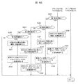
- 4 is a flowchart illustrating a first half of a control flow for executing control from a start to a maximum load region in the variable valve system for an internal combustion engine according to the first embodiment of the present invention.
- 4 is a flowchart illustrating a latter half of a control flow for executing control from a start to a maximum load region in the variable operation system of the internal combustion engine according to the first embodiment of the present invention.
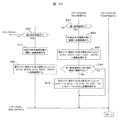
- FIG. 6 is a flowchart illustrating a control flow according to a modification of the first embodiment of the present invention.
- FIG. 8 is an explanatory diagram illustrating a relationship between a valve overlap between an exhaust valve and an intake valve from a start to a maximum load region and a valve timing between the intake valve and the exhaust valve in a modified example of the first embodiment of the present invention.
- FIG. 8 is an explanatory diagram illustrating a relationship between a load region, valve characteristics of an intake valve and an exhaust valve, and an opening of an external EGR valve according to a second embodiment of the present invention. It is a flowchart which shows the control flow of the variable operation system of the internal combustion engine which becomes 2nd Embodiment of this invention.
- FIG. 1 shows the overall configuration of a variable valve system for an internal combustion engine to which the present invention is applied.
- a piston 01 slidably provided up and down by a combustion pressure or the like in a cylinder bore formed in a cylinder block CB.
- An intake port IP and an exhaust port EP respectively formed inside the cylinder head CH, and a pair of intakes per cylinder each slidably provided in the cylinder head CH to open and close the open ends of the intake and exhaust ports IP and EP.
- a valve 4 and an exhaust valve 5 are provided.
- the piston 01 is connected to the crankshaft via the connecting rod 02 and forms a combustion chamber 04 between the crown surface 03 and the lower surface of the cylinder head CH.
- An ignition plug 05 is provided substantially at the center of the cylinder head CH.
- the intake port IP is connected to the air cleaner 50, and the intake air is supplied through the electronically controlled throttle valve 51.
- the exhaust port EP discharges exhaust gas from the tail pipe to the atmosphere via the exhaust gas purification catalyst 53.
- the downstream of the exhaust gas purification catalyst 53 and the upstream of the electronically controlled throttle valve 51 are connected by an exhaust gas recirculation passage (hereinafter, referred to as an external EGR passage) 54.
- An EGR cooler 55 for cooling the external EGR gas, and an external EGR valve 56 disposed downstream of the cooler 55 for controlling the flow rate of the external EGR gas are provided.
- the external EGR valve 56 is an electronically controlled valve driven by an electric motor, and adjusts the external EGR gas flow rate according to a control signal from the controller 52.
- the external EGR valve 56 a butterfly valve or the like is used, and the external EGR gas can be controlled from a minimum opening position where the flow rate of the external EGR gas is reduced to substantially “0” to a large opening position where a large amount of the external EGR gas flows.
- the large opening position may be an opening position at which the maximum flow rate is obtained, but is not limited to this, and may be an opening position set according to a required required flow rate.
- the external EGR valve 56 has a fail-safe function in which, when an abnormality or failure occurs, the drive signal is cut off and the external EGR valve 56 is mechanically set to the minimum opening position.
- the present embodiment is a so-called “LP-EGR system” (low pressure EGR system) in which the external EGR gas is extracted from a portion downstream of the exhaust gas purification catalyst 53 where the exhaust pressure and the exhaust temperature have decreased to some extent.
- L-EGR system low pressure EGR system
- the temperature of the external EGR gas is further lowered to prevent knocking in a high load region. I try to improve the nature. That is, since the temperature of the exhaust gas supplied from the external EGR valve 56 is low, the temperature of the whole mixed gas supplied into the combustion chamber tends to be low.
- the internal combustion engine is provided with an intake-side variable valve mechanism and an exhaust-side variable valve mechanism for controlling the opening characteristics of the intake valve 4 and the exhaust valve 5.
- an intake-side variable valve mechanism (hereinafter, referred to as an intake-side VTC mechanism) 1A, which is a “phase angle variable mechanism” that controls the central phase angle of the valve lift of the intake valve 4.
- an exhaust-side variable valve mechanism (hereinafter, referred to as an exhaust-side VTC mechanism) 1B, which is a “phase angle variable mechanism” that controls the central phase angle of the valve lift of the exhaust valve 5, is provided.
- the intake-side VTC mechanism 1A and the exhaust-side VTC mechanism 1B include phase-control hydraulic actuators 2A and 2B, and are configured to control the opening and closing timing of the intake valve 4 and the exhaust valve 5 by hydraulic pressure.
- the hydraulic pressure supply to the phase control hydraulic actuators 2A and 2B is controlled by a hydraulic control unit (not shown) based on a control signal from the controller 52.
- a hydraulic control unit not shown
- the center phase of the lift characteristic is controlled to the retard side or the advance side.
- the exhaust camshaft 10 is provided with two exhaust cams 11 per cylinder.
- the exhaust cam 11 opens and closes the exhaust valve 5.
- a sprocket mechanism 13 and an exhaust-side VTC mechanism 1B fixed to the sprocket mechanism 13 are attached, and the exhaust camshaft 10 is rotated relative to the sprocket mechanism 13 (phase conversion).
- the relative rotation position of the exhaust cam 11 is controlled.
- the sprocket mechanism 13 includes a timing sprocket 15, and is rotated by a timing belt (not shown) in synchronization with the crankshaft.
- the exhaust-side VTC mechanism 1B includes a housing 16 and a vane driven by hydraulic pressure in a space defined by a front cover 17 and a rear cover 18 fixed to both ends of the housing 16. The timing sprocket 15 and the rear cover 18 are fixed to each other, and the vane is fixed to the exhaust cam shaft 10.
- the exhaust camshaft 10 adjusts the opening / closing phase of the exhaust valve correspondingly.
- the hydraulic pressure in the housing 16 is controlled by an exhaust electromagnetic switching valve 29, and the exhaust electromagnetic switching valve 29 is driven by a controller 52.
- the intake camshaft 20 is provided with two intake cams 21 per cylinder.
- the intake cam 21 opens and closes the intake valve 4.
- a sprocket mechanism 23 and an intake-side VTC mechanism 1A fixed to the sprocket mechanism 23 are attached to one end of the intake camshaft 20, and the intake camshaft 20 is rotated relative to the sprocket mechanism 23 (phase conversion).
- the relative rotational position of the intake cam 21 is controlled.
- the sprocket mechanism 23 includes a timing sprocket 25, and is rotated by a crank shaft by a timing belt (not shown).
- the intake-side VTC mechanism 1A includes a housing 26 and a vane driven by hydraulic pressure in a space defined by a front cover 27 and a rear cover 28 fixed to both ends of the housing 26.
- the timing sprocket 25 and the rear cover 28 are fixed to each other, and the vane is fixed to the intake camshaft 20.
- the intake camshaft 20 adjusts the opening / closing phase of the intake valve correspondingly.
- the hydraulic pressure in the housing 26 is controlled by the intake electromagnetic switching valve 30, and the intake electromagnetic switching valve 30 is driven by the controller 52.
- the default position “the most retarded position” is used both when the hydraulic pressure is supplied from the hydraulic pump and when the control signal is interrupted and the hydraulic pressure is not supplied. ”.
- the default position is a position that is mechanically stable (mechanically stable position).
- a bias spring for urging the vane to the most retarded side is used, and when the operating oil pressure does not act on the vane, it is stable around this "most retarded position”. It is supposed to. Then, when the rotation speed decreases in the state of the phase angle, the hydraulic pressure decreases, and the pin locks at a phase near the “most retarded position”.
- the “most retarded position” is an opening timing of the intake valve 4 (hereinafter, referred to as an intake opening timing (IVO)) set in a “low load region” which is a “first load region” described later.
- IVO1 intake opening timing
- a certain first intake opening timing (IVO1) is reached. This is shown as valve timing in the first load region in FIG.
- the default position (the mechanically stable position) is “the most advanced angle”. The position is controlled in the vicinity.
- a bias spring that urges the vane to the advance side is used, and when the operating oil pressure does not act on the vane, the vane is stabilized near the “most advanced position”. It has become. Then, when the rotational speed decreases in this phase, the hydraulic pressure decreases, and the pin locks at a phase near the “most advanced position”.
- the “most advanced position” is a closing timing of the exhaust valve 5 (hereinafter referred to as an exhaust closing timing (EVC)) set in a “low load region” which is a “first load region” described later. Becomes the first exhaust closing timing (EVCl). This is also shown in FIG. 3 as the valve timing in the first load region.
- EDC exhaust closing timing
- control means 52 includes an output signal from a crank angle sensor for detecting the current rotational speed Ne (rpm) of the internal combustion engine from the crank angle, an intake air amount (load) from the air flow meter. ), An accelerator opening sensor, a vehicle speed sensor, a gear position sensor, an engine cooling water temperature sensor 31 for detecting the temperature of the engine body, and various information signals such as an output signal from an atmospheric humidity sensor. The state is being detected.
- the controller 52 outputs an intake VTC control signal to at least the intake side VTC mechanism 1A, outputs an exhaust VTC control signal to the exhaust side VTC mechanism 1B, and outputs an external EGR gas to the external EGR valve 56. It outputs a control signal.
- the intake-side VTC mechanism 1A and the exhaust-side VTC mechanism 1B use a hydraulic type. However, an electric type may be used, and both an electric type and a hydraulic type may be used. It can also be used.
- an internal combustion engine that forms a positive valve overlap section (PVO) by the intake-side VTC mechanism 1A and the exhaust-side VTC mechanism 1B when operating at a medium load is used.
- the exhaust-side VTC mechanism 1B sets the exhaust closing timing (EVC) of the exhaust valve 5 to a predetermined angular position (EVC1) before the exhaust top dead center (TDC) and sets the intake air.
- the side VTC mechanism 1A delays the intake opening timing (IVO) of the intake valve 4 to a predetermined angular position (IVO1) after the exhaust top dead center (TDC) to form a negative valve overlap section.
- FIG. 3 shows the valve timing of the intake valve 4 and the exhaust valve 5 and the operating state of the external EGR valve by the variable valve mechanism corresponding to the load region.
- FIG. 4 shows the variable valve mechanism corresponding to the change of the load region.
- FIG. 5 shows the valve timing of the intake valve 4 and the exhaust valve 5 and the state of change of the valve overlap.
- FIG. 5 shows the valve overlap of the intake valve 4 and the exhaust valve 5 by the variable valve mechanism corresponding to the change of the load region.
- 3 shows a change state of the EGR rate in the combustion chamber and the gas temperature in the combustion chamber.
- First Load Region (Low Load Region Including Idle) >>
- the exhaust closing timing (EVC) is advanced from the exhaust top dead center (TDC) by a predetermined angle (ED1) to the advanced side, here the most advanced position.
- EVO is set to the first exhaust opening timing (EVO1)
- the exhaust closing timing (EVC) of the exhaust valve 5 is set to the first exhaust closing timing (EVC1) before the exhaust top dead center (TDC). Is done.
- the intake opening timing (IVO) of the intake valve 4 is retarded by a predetermined angle (ID1) from the exhaust top dead center (TDC) by the intake side VTC mechanism 1A, starting from the exhaust top dead center (TDC), here to the most retarded position.
- the intake opening timing (IVO) of the intake valve 4 is set to a first intake opening timing (IVO1) after the exhaust top dead center (TDC), and the intake closing timing (IVC) of the intake valve 4 is set. Is set to the first intake closing timing (IVC1).
- the exhaust top dead center (TDC) is synonymous with the intake top dead center (TDC) in the next stroke.
- the first exhaust closing timing (EVC1) of the exhaust valve 5 is set to be advanced by a predetermined angle (ED1) before the exhaust top dead center (TDC), and the first exhaust opening timing (IVO1) of the intake valve 4 is set.
- ED1 a predetermined angle
- IVO1 the first exhaust opening timing
- NVO1 the angle of the negative valve overlap section
- the predetermined angle (ID1) and the predetermined angle (ED1) are set to substantially the same angle.
- the substantially same angle means that the exhaust-side VTC mechanism 1B and the intake-side VTC mechanism 1A are mechanically assembled. This is a concept including errors and design tolerances, and does not necessarily mean the same angle.
- the first intake opening timing of the intake valve 4 IVO1 is delayed by a predetermined angle (ID1) starting from the exhaust top dead center (TDC), and the first exhaust closing timing (EVC1) of the exhaust valve 5 is started from the exhaust top dead center (TDC).
- ID1 a predetermined angle starting from the exhaust top dead center
- EDC1 the first exhaust closing timing of the exhaust valve 5 is started from the exhaust top dead center (TDC).
- the valve is advanced by a predetermined angle (ED1), and a negative valve overlap section (NVO1) is formed between the intake valve 4 and the exhaust valve 5.
- the exhaust valve 5 is closed at a predetermined advance angle (ED1) before the piston 01 reaches the exhaust top dead center (TDC), and the exhaust valve 5 reaches the exhaust top dead center (TDC). Since the intake valve 4 is opened at a predetermined angle (ID1) on the retard side after the combustion, the high-temperature combustion gas is contained as a high-temperature internal EGR gas in the combustion chamber without being cooled. In addition, the high-temperature internal EGR gas is compressed by the piston 01 until it reaches exhaust top dead center (TDC), so that the internal EGR gas further becomes high pressure and high temperature and the combustion chamber is maintained at a high temperature.
- ED1 advance angle
- ID1 exhaust top dead center
- the high temperature combustion gas (internal EGR gas) is supplied from the end of the exhaust stroke to the early stage of the intake stroke.
- the temperature of the internal EGR gas in the combustion chamber remaining near the top dead center (TDC) of the exhaust gas can be further increased by the "contained internal EGR gas" by pressurizing with a piston.
- the internal EGR gas remaining in the combustion chamber is sufficiently heated, so that combustion in a low load region where unstable combustion is likely to occur can be improved, and fuel efficiency can be improved.
- the first exhaust valve 5 is closed.
- the pressure in the combustion chamber at the closing timing (EVC1) and the pressure in the combustion chamber at the first intake opening timing (IVO1) at which the intake valve 4 opens are substantially equal, and the pump loss in the negative valve overlap section (NVO) is obtained. Is suppressed as much as possible.
- fresh air gas is introduced through the intake valve 4.
- This fresh gas is originally introduced from the atmosphere through an air cleaner or an intake passage, and its temperature is considerably lower than that of the internal EGR.
- the low-temperature fresh gas is heated by being mixed with the high-temperature internal EGR gas sealed in the combustion chamber.
- This contained internal EGR gas is sufficiently higher than the internal EGR gas in the normal positive valve overlap section (PVO), and as a result, the gas temperature in the combustion chamber at the intake bottom dead center (BDC) is as shown in FIG. As shown by the gas temperature (T1), the combustion becomes stable even at a low load, and the fuel efficiency can be improved.
- FIG. 5 shows the EGR rate in the combustion chamber and the gas temperature in the combustion chamber (for example, the temperature at the bottom dead center (BDC) of the intake air) with respect to the change in the load condition.
- the formation of the negative valve overlap section (NVO1) enables the “containment internal EGR”, and the high-temperature combustion gas (internal EGR gas) )
- the EGR rate (R1) in the combustion chamber can be maintained at, for example, about 20% only by the internal EGR gas, and the gas temperature can be maintained high.
- the internal EGR gas burnt Since the exhaust gas is re-inhaled, the temperature of the internal EGR gas is lowered by the low-temperature intake system in the process, and the mixing of the internal EGR gas in the volume of the intake system is likely to be uneven. Therefore, the flow rate of the internal EGR gas re-introduced into each cylinder via the intake valve 4 varies between cylinders, and the combustion of the air-fuel mixture becomes more unstable as a whole.
- the mixed gas in the combustion chamber is compared with the “re-intake internal EGR” by PVO described above. Is maintained at a high temperature.
- the EGR rate of the contained internal EGR gas is determined by the valve timing (EVCl, IVOl) of the intake valve 4 and the exhaust valve 5, and the variation in the amount of the internal EGR gas due to the intake system between cylinders does not occur in principle. . That is, it is possible in principle to avoid inter-cylinder variation of the EGR gas amount generated in the internal EGR due to the positive valve overlap section (PVO), thereby further stabilizing combustion and stabilizing the engine rotation. , Fuel efficiency can be improved.
- the external EGR valve 56 since the external EGR valve 56 is controlled to be almost fully closed, the external EGR gas of a low temperature by the external EGR system is re-introduced, for example, only at a predetermined small flow rate or less. Alternatively, since it is not desirably re-introduced, the above-described effect of the “containment inside EGR” can be sufficiently obtained.
- the EGR gas is an inert gas. Regardless of the internal EGR and the external EGR, if the EGR rate is high, the engine torque decreases, and the throttle opening can be increased to obtain the same engine torque, Since pump loss during the intake stroke can be reduced, fuel efficiency can be improved.
- EGR gas is an inert gas containing almost no oxygen, and has a drawback that when the EGR rate is increased, combustion deteriorates. Therefore, it is difficult to increase the EGR rate particularly in a low load region where combustion is not stable.
- NVO1 negative valve overlap section
- the first intake closing timing (IVC1) of the intake valve 4 is retarded from the intake bottom dead center (BDC), so that the so-called late closing Miller cycle (Atkinson cycle) effects. Fuel efficiency can be improved.
- valve timing characteristics of the intake valve 4 and the exhaust valve 5 are the same in the low load region including the cranking and the idle from the stop state of the internal combustion engine. Therefore, before the internal combustion engine is stopped until the second load region is reached, the negative valve overlap section in the stopped state, the negative valve overlap section in the cranking state, the negative valve overlap section in the idle state, and The same negative valve overlap section (NVO1) as the negative valve overlap section before reaching the second load region is formed.
- EVO opening / closing timing
- the opening degree of the external EGR valve 56 is set to the same minimum opening degree until the stop state, the cranking state, the idle state, and before reaching the second load region.
- the configuration is not re-introduced.
- the intake-side VTC Control of the mechanism 1A, the exhaust-side VTC mechanism 1B, and the external EGR valve 56 can be simplified. Furthermore, in the present embodiment, when the electric control system of the intake-side VTC mechanism 1A, the exhaust-side VTC mechanism 1B, and the external EGR valve 56 fails, they are stabilized at their respective default positions, and fail-safe control is also performed. Simplified.
- the exhaust valve VTC mechanism 1B uses the exhaust valve.
- the closing timing (EVC) of the exhaust valve 5 is retarded by a predetermined angle (ED2) from the exhaust top dead center (TDC) to the retard side, here the most retarded position.
- EVO is set to the second exhaust opening timing (EVO2)
- the exhaust closing timing (EVC) of the exhaust valve 5 is set to the second exhaust closing timing (EVC2).
- the opening timing (IVO) of the intake valve 4 is advanced by a predetermined angle (ID2) from the exhaust top dead center (TDC) to the advanced side, here the most advanced position, by the intake side VTC mechanism 1A.
- the intake opening timing (IVO) of the intake valve 4 is set to the second intake opening timing (IVO2) 2
- the intake closing timing (IVC) of the intake valve 4 is set to the second intake closing timing (IVC2).
- the second exhaust closing timing (EVC2) of the exhaust valve 5 is set to the retard side by a predetermined angle (ED2) after the exhaust top dead center (TDC), and the second intake opening timing (IVO2) of the intake valve 4 is set.
- ED2 exhaust top dead center
- IVO2 second intake opening timing
- PVO2 positive valve overlap section
- the intake valve 4 is set to the most retarded position in the first load region
- the exhaust valve 5 is set to the most advanced position
- the intake valve 4 is set to the most advanced position in the second load region.
- the exhaust valve 5 is set to the most retarded position, so that the relationship of ED1 ⁇ ID1 ⁇ ED2 ⁇ ID2 is established.
- the second intake opening timing (IVO2) of the intake valve 4 is set at the exhaust top dead center (IVO2).
- TDC exhaust top dead center
- ID2 the second exhaust closing timing
- EVC2 the second exhaust closing timing of the exhaust valve 5 is set at a predetermined point starting from the exhaust top dead center (TDC).
- the valve is switched by the angle (ED2) like a switch and retarded, and a positive valve overlap section (PVO2) is formed between the intake valve 4 and the exhaust valve 5.
- the intake valve 4 is opened at a predetermined angle (ID2) on the advance side before the piston 01 reaches the exhaust top dead center (TDC), and the exhaust top dead center (TDC) Then, the exhaust valve 5 is closed at a predetermined angle (ED2) on the retard side after reaching.
- ID2 a predetermined angle
- ED2 a predetermined angle
- the combustion gas (internal EGR gas) is returned to the intake system once, and then sucked into the combustion chamber again, and the "re-intake internal EGR" Gas ".
- the internal EGR gas returned to the intake system is cooled in the intake system and then introduced into the combustion chamber, so that the gas temperature in the combustion chamber at the intake bottom dead center (BDC) becomes the temperature. The temperature falls from (T1) to the temperature (T2).
- the temperature of the mixed gas in the combustion chamber is reduced, so that knocking is suppressed, and the frequency and amount of retard control of the ignition timing can be suppressed, thereby improving and improving fuel efficiency.
- the temperature of the internal EGR gas is higher than the temperature of the external EGR gas, so that the gas temperature in the combustion chamber can be maintained at a sufficient temperature (T2) required for combustion. Therefore, deterioration of combustion can be suppressed while suppressing knocking, so that good fuel economy performance can be obtained.
- the external EGR gas having a low temperature by the external EGR system is, for example, equal to or less than a predetermined small flow rate. Is re-introduced or desirably is not re-introduced, so that the above-described effect of the "re-intake internal EGR" can be sufficiently obtained.
- the opening degree of the external EGR valve 56 is set to the same minimum opening degree over almost the entire second load region, so that the low-temperature external EGR gas by the external EGR system is not re-introduced.
- the formation of the positive valve overlap section (PVO2) causes the “re-intake internal EGR gas” to be compared with the internal EGR gas in the negative valve overlap section (NVO1). Since the low-temperature internal EGR gas is introduced into the combustion chamber, the EGR rate (R2) in the combustion chamber can be maintained at, for example, about 20% with only the re-intake internal EGR gas, and the gas temperature is required. It can be maintained at a sufficient temperature (T2).
- the EGR rate is determined by the total value of the internal EGR gas for the combustion chamber and the internal EGR gas re-inhaled.
- the EGR rate (R1) due to the “containment internal EGR gas” and the EGR rate due to the “re-intake internal EGR gas” in the positive valve overlap section (PVO2) can be made substantially the same.
- the overlap section in the positive valve overlap section (PVO2), fresh air gas is also sucked together when "re-intake internal EGR gas" is sucked, so in the case of a multi-cylinder integrated intake system, the overlap section is set to (PVO2). )> (NVO1), the EGR rates of both can be made even closer.
- the overlap section is set to (PVO2) ⁇ (NVO1), assuming that the intake ports of each cylinder are accurately separated and formed.
- an EGR rate of about 20% is maintained even when the negative valve overlap section (NVO1) shifts to the positive valve overlap section (PVO2).
- the positive valve overlap (PVO) and the negative valve overlap (NVO) are not formed between the first load region and the second load region, and the zero valve overlap (“0” VO) (Low EGR region), but since the load determination thresholds for separating the first load region and the second load region are almost the same, when FIG.
- the graph is drawn such that the EGR rate of about 20% continues, ignoring the low EGR area.
- the low EGR region may become apparent, and this will be described with reference to the control flowchart of FIG.
- the “containment internal EGR gas” in the second load region shown in FIG. 5 is a gas amount corresponding to the volume of the combustion chamber at the lift position of the piston 01 when the exhaust top dead center (TDC) is reached. This gas amount exists even in the case of “re-intake internal EGR” or in the case of “external EGR” described later.
- the total gas amount obtained by adding the “contained internal EGR gas” and the “reintake internal EGR gas” of the combustion chamber volume corresponds to the EGR gas amount in the second load region in FIG.
- the second intake closing timing (IVC2) of the intake valve 4 is set close to the intake bottom dead center (BDC).
- the intake valve 4 is advanced to just before the intake bottom dead center (BDC). The effect can further reduce the pump loss and improve the fuel efficiency.
- the temperature of the mixed gas in the combustion chamber becomes high even when the “re-intake internal EGR” is performed in the positive valve overlap section (PVO2), and knocking occurs. It will be easier. For this reason, control for increasing the concentration of the air-fuel mixture or delaying the ignition timing is executed, which leads to deterioration of fuel efficiency.
- the closing timing (EVC) of the exhaust valve 5 is advanced toward the top dead center (TDC) side of the second load region, and the exhaust opening timing (EVO) of the exhaust valve 5 is set to the third exhaust opening timing (EVO3). And the exhaust closing timing (EVC) of the exhaust valve 5 is set to the third exhaust closing timing (EVC3).
- the intake valve 4 is retarded from the exhaust top dead center (TDC) side by the intake side VTC mechanism 1A as compared with the second load region, and the intake opening timing (IVO) of the intake valve 4 is set to the third position.
- the intake opening timing (IVO3) ⁇ is set, and the intake closing timing (IVC) of the intake valve 4 is set to the third intake closing timing (IVC3).
- the third exhaust closing timing (EVC3) of the exhaust valve 5 is set to the exhaust top dead center (TDC), and the third intake opening timing (IVO3) of the intake valve 4 is also set to the exhaust top dead center (TDC). Therefore, the operating angle of the exhaust valve 5 and the operating angle of the intake valve 4 do not overlap, and the zero valve overlap (“0” VO) is formed in which the negative valve overlap section (NVO) is not formed. Thus, the operation of the “re-suction internal EGR” is stopped. Instead, the operation of the “external EGR” is executed as shown in the third load region of FIG.
- the exhaust closing timing (EVC) of the exhaust valve 5 is advanced from the second exhaust closing timing (EVC2) to the third exhaust closing timing (EVC3),
- the operation of the intake opening timing (IVO) of the intake valve 4 is delayed from the second intake opening timing (IVO2) to the third intake opening timing (IVO3).
- the external EGR gas is gradually increased, so that the gas temperature in the combustion chamber is rapidly increased by the external EGR gas. , And the gas temperature in the combustion chamber is gradually reduced, so that the combustion state including the transient performance can be stabilized.
- the gas temperature in the cylinder gradually decreases.
- the transient variation in the EGR gas flow rate between the cylinders can be suppressed, it is possible to suppress the instability of the transient performance, which is likely to occur in the process from the middle load range to the high load range.
- the EGR rate (R3) in the combustion chamber in FIG. 5 indicates the sum of the gas amount in the “containment internal EGR” and the gas amount in the “external EGR”, and this value is maintained at about 20%. From that aspect, it is possible to stabilize the transient performance when shifting to a direction where the load increases toward the high load region.
- the intake opening timing (IVO) of the intake valve 4 is shifted to the exhaust top dead center (TDC) in the third load region, and the third intake region is shifted.
- the opening timing (IVO3) is set, and the exhaust closing timing (EVC) of the exhaust valve 5 is advanced to the exhaust top dead center (TDC) to set the third exhaust closing timing (EVC3).
- the intake closing timing (IVC) of the intake valve 4 also changes from near the middle position between the intake bottom dead center (BDC) and the compression top dead center (TDC). It is shifted to the retard side until the third intake closing timing (IVC3) toward the intake bottom dead center (BDC).
- the exhaust opening timing (EVO) of the exhaust valve 5 also moves toward the intake bottom dead center (BDC) side until the third exhaust opening timing (EVO3). It has been shifted to the advanced side.
- the third exhaust closing timing (EVC3) of the exhaust valve and the third intake opening timing (IVO3) of the intake valve are set close to each other near the exhaust top dead center (TDC).
- the zero valve overlap valve (“0” VO3) is formed in the third load region, the “containment internal EGR” due to the high temperature combustion gas caused by the negative valve overlap section (NVO) is almost zero. Will not work. Further, the “re-suction internal EGR” caused by the positive valve overlap section (PVO) also hardly functions.
- the external EGR valve 56 is greatly opened to the maximum opening degree, so that a predetermined large amount of external EGR gas is introduced into the combustion chamber.
- the temperature of the external EGR gas is low, and the temperature is further lowered by the EGR cooler 55.
- the gas temperature in the cylinder into which the external EGR gas has been introduced becomes low, and abnormal combustion such as knocking is unlikely to occur in combination with the low-temperature combustion effect based on the EGR gas. Therefore, the ignition timing can be advanced, so that the combustion efficiency can be increased, and the fuel efficiency performance in the third load region can be improved.
- both the “containment internal EGR” and the “re-suction internal EGR” hardly function due to the formation of the zero valve overlap valve (“0” VO3). Since the low-temperature external EGR gas is re-introduced instead, it is understood that the gas temperature can be lowered from the gas temperature (T2) to the gas temperature (T3) as shown in FIG.
- the ignition timing can be advanced while avoiding abnormal combustion such as knocking. As a result, the combustion efficiency can be improved, and the fuel efficiency in the third load region can be improved.
- the “containment internal EGR gas” does not function, but as shown in FIG. 5, the “containment internal EGR gas” remains slightly. This means that at exhaust top dead center (TDC), the combustion gas remains in the volume between the crown surface of the piston 01 and the upper wall of the combustion chamber, and in the next intake stroke, it becomes “contained internal EGR gas”. It is to remain.
- TDC exhaust top dead center
- the intake-side VTC mechanism 1A and the exhaust-side VTC mechanism 1B can be simplified, and since the EGR rate in the combustion chamber can be maintained at the same level, the transient performance can be stabilized even when the load suddenly changes. .
- the introduction of the external EGR gas is stopped by setting the external EGR valve 56 to the minimum opening degree (fully closed), and the opening / closing timing of the intake valve 4 is further kept the same as in the third load region.
- the exhaust valve closing timing (EVC) of the exhaust valve 5 is retarded to the fourth exhaust closing timing (EVC4), and the exhaust opening timing (EVO) is similarly retarded to the fourth exhaust opening timing (EVO4).
- the valve is retarded to the bottom dead center (BDC) of the exhaust gas to form a positive valve overlap (PVO4).
- BDC bottom dead center
- PVO4 positive valve overlap
- the fourth intake opening timing (IVO4) of the intake valve 4 is set to the exhaust top dead center. (TDC), and the exhaust valve closing timing (EVC) of the exhaust valve 5 is shifted to the retard side after the exhaust top dead center (TDC) to be the fourth exhaust closing timing (EVC4).
- the intake closing timing (IVC4) of the intake valve 4 is set to the intake bottom dead center (BDC)
- the fourth exhaust opening timing (EVO4) of the exhaust valve 5 is set to the expansion bottom dead center (BDC).
- the zero valve overlap is caused by the fourth exhaust closing timing (EVC4) of the exhaust valve and the fourth intake opening timing (IVO4) of the intake valve.
- EVC4 exhaust closing timing
- IVO4 intake opening timing
- a positive valve overlap section (PVO4) is formed for "0" VO3).
- the phase angle of the positive valve overlap section gradually increases in response to the increase in load. It is adjusted in the direction. Also, as shown in FIG. 5, the opening of the external EGR valve 56 is controlled correspondingly in the range of the minimum opening by decreasing the opening, and the external EGR gas amount becomes substantially “0” in the fourth load region. ".
- the opening degree of the external EGR valve 56 is gradually reduced from the third load region to the fourth load region, and in addition, the positive valve overlap section (PVO) is also reduced to the zero valve overlap section (“0” VO3).
- PVO4 the positive valve overlap section
- the EGR rate has decreased to almost “0” due to the crown of the piston 01 at the top dead center (TDC) of the exhaust gas.
- the combustion gas between the surface and the upper wall of the combustion chamber is taken into the combustion chamber as a confined internal EGR in the next intake stroke, and this combustion gas is also drawn out to the exhaust port side by the above-mentioned scavenging effect. That's why.
- a fresh gas having a lower temperature is introduced, and the fresh gas is lower in temperature than the external EGR gas. Therefore, as shown in FIG.
- the temperature can be lowered to the temperature (T4) to improve the knock resistance.
- the introduction of the fresh gas means that the charging efficiency is increased, and the engine torque can also be increased.
- the positive valve overlap section (PVO) and the negative valve overlap section (NVO) are appropriately set according to the load area, so that the good valve overlap section (NVO) can be obtained over a wide load area.
- the fuel efficiency can be improved, and the engine torque can be increased.
- the opening and closing timings of the intake valve 4 and the exhaust valve 5 in the first load region are almost the same as the default positions of the intake-side VTC mechanism 1A and the exhaust-side VTC mechanism 1B.
- This default position is a mechanically stable position when the conversion power of the intake-side VTC mechanism 1A and the exhaust-side VTC mechanism 1B does not act.
- the opening / closing timing of the intake valve 4 and the exhaust valve 5 in the first load region from the time of stopping and the time of cranking is set to this default position. Therefore, the above-described combustion improvement effect can be obtained immediately after the cranking is performed and the combustion is started by the engine start. In particular, at the time of cooling, the cold startability can be remarkably improved by the combustion improvement effect.
- the load determination threshold is set to “L (1 ⁇ 2)” when shifting from the first load area to the second load area, and the load determination threshold is set to “L (1 ⁇ 2)” when shifting from the second load area to the first load area.
- L (1 ⁇ 2) -h the load determination threshold is set to “L (1 ⁇ 2)” when shifting from the second load area to the first load area.
- NVO1 negative valve overlap section
- PVO2 positive valve overlap section
- step S20 engine start information for starting the internal combustion engine and operating condition information of the internal combustion engine are read.
- Engine start information for starting the internal combustion engine typically includes a key-on signal or a starter start signal, and there are many signals indicating operating condition information of the internal combustion engine.
- the information includes rotational speed information, intake air amount information, water temperature information, required load information (accelerator opening), and the like, and further includes actual position information of the exhaust-side VTC mechanism 1B and the intake-side VTC mechanism 1A.
- step S21 it is determined whether an engine start condition is satisfied. This determination can be made, for example, by monitoring the starter start signal. If the starter start signal is not input, the process returns to the start and waits for the next start timing. On the other hand, when the starter start signal is input, it is determined that an engine start condition is satisfied, and the process proceeds to step S22.
- step S22 the cranking of the internal combustion engine by the starter motor is started in response to the starter start signal. Then, as soon as the cranking is started, the process proceeds to step S23.
- Step S23 At least the exhaust valve closing timing (EVC) and the intake valve opening timing (IVO) of the exhaust valve are shifted to the default position for the exhaust-side VTC mechanism 1B and the intake-side VTC mechanism 1A. Are output to the exhaust electromagnetic switching valve 29 of the exhaust-side VTC mechanism 1B and the intake electromagnetic switching valve 30 of the intake-side VTC mechanism 1A.
- EMC exhaust valve closing timing
- IVO intake valve opening timing
- the negative valve overlap section (NVO1) is reliably formed as the negative valve overlap section (NVO). As shown in FIG. 4, the negative valve overlap section (NVO1) in the stop state, the idle state, and the first load region aims at the same negative valve overlap section (NVO).
- step S24 when the conversion control signal is output to the exhaust electromagnetic switching valve 29 of the exhaust-side VTC mechanism 1B and the intake electromagnetic switching valve 30 of the intake-side VTC mechanism 1A, the process proceeds to step S24.
- Step 24 based on the actual position information of the exhaust-side VTC mechanism 1B and the intake-side VTC mechanism 1A, whether the exhaust-side VTC mechanism 1B and the intake-side VTC mechanism 1A have shifted to the default positions, It is determined whether the exhaust closing timing (EVC) of the valve 5 is set to the first exhaust closing timing (EVC1) and whether the intake opening timing (IVO) of the intake valve 4 is set to the first intake opening timing (IVO1). Is done.
- EDC exhaust closing timing
- IVO intake opening timing
- step S23 When it is determined that the exhaust valve 5 is not set to the first exhaust closing timing (EVC1) and the intake valve 4 is not set to the first intake opening timing (IVO1), the process returns to step S23 again.
- the process proceeds to step S25.
- step S25 an output control signal is supplied to the fuel injection valve and the ignition device to start the internal combustion engine in accordance with the rotation of the starter motor.
- the rotation speed of the internal combustion engine increases, and accordingly, the hydraulic pressure of the hydraulic oil of the hydraulic pump increases.
- Step S26 the engine temperature (cooling water temperature) of the internal combustion engine is detected to determine whether or not the temperature has exceeded a predetermined temperature. If the temperature does not exceed the predetermined temperature, it is determined that the engine is in the cold state, and the process returns to wait for the next start timing or executes another control flow. On the other hand, if the temperature exceeds the predetermined temperature, it is determined that the warm-up is completed from the cold state, and the operation condition information is read again and the process proceeds to step S27. It is to be noted that FIG.
- step S27 the current load state is detected from the opening of the throttle valve or the opening of the accelerator pedal to determine whether the current load is in the first load region, which is a low load region. Judge whether or not. If it is determined that the region is the first load region, the process proceeds to step S28, in which the opening of the external EGR valve 56 is converted and controlled to the minimum opening.
- step S29 in which the exhaust-side VTC mechanism 1B and the intake-side VTC mechanism 1A are driven, and the first exhaust closing timing (EVC1) of the exhaust valve in the first load region and the first intake of the intake valve are performed. Control is performed at the opening timing (IVO1) to form a negative valve overlap section (NVO1).
- step S29 When the process in step S29 is completed, the process returns to the start and waits for the next controller activation timing. On the other hand, if it is determined in step S27 that the current load is not in the first load region, the process proceeds to step S30.
- step S30 the current load state is detected from the opening of the throttle valve or the opening of the accelerator pedal, and it is determined whether the current load is in the second load region. If it is determined that the load region is the second load region, the process proceeds to step S31, in which the opening of the external EGR valve 56 is controlled to be converted to the minimum opening.
- step S32 in which the exhaust-side VTC mechanism 1B and the intake-side VTC mechanism 1A are driven, the second exhaust closing timing (EVC2) of the exhaust valve in the second load region, and the second intake of the intake valve.
- EVC2 the second exhaust closing timing of the exhaust valve in the second load region
- PVO2 a positive valve overlap section
- step S32 When the process of step S32 is completed, the process returns to the start and waits for the next controller start timing. On the other hand, if it is determined in step S30 that the current load is not in the second load region, the process proceeds to step S33.
- step S33 the current load state is detected from the opening of the throttle valve or the opening of the accelerator pedal, and it is determined whether or not the current load is in the third load region. It should be noted that this third load region is determined to include the transition load regions P and H shown in FIGS. Therefore, when it is determined that the load region is the third load region, the process proceeds to step S34. When it is further determined that the load region is the transition load region P, the opening degree of the external EGR valve 56 is adjusted so that the EGR rate shown in FIG. Is converted into an opening corresponding to the detected load.
- step S35 in which the exhaust-side VTC mechanism 1B and the intake-side VTC mechanism 1A are driven according to the detected load, and the third exhaust closing timing (EVC3) of the exhaust valve in the third load region is determined. And the third intake opening timing (IVO3) of the intake valve to form a zero valve overlap ("0" VO3).
- the load region is the transition load region H
- the opening of the external EGR valve 56 is converted and controlled to an opening corresponding to the detected load so that the EGR rate shown in FIG. 5 is obtained.
- the positive valve from the positive valve overlap section (PVO2) to the zero valve overlap (“0” VO3) is determined, as shown in FIG. 5, the positive valve from the positive valve overlap section (PVO2) to the zero valve overlap (“0” VO3).
- the intake valve 4 and the exhaust valve 5 are provided so that an overlap section (PVO) or a positive valve overlap section (PVO) from a zero valve overlap (“0” VO3) to a positive valve overlap section (PVO4) is obtained.
- the open / close timing is converted and controlled to an open / close timing corresponding to the detected load.
- step S35 When the process in step S35 is completed, the process returns to the start and waits for the next start timing. On the other hand, if it is determined in step S33 that the current load is not in the third load region, the process proceeds to step S36.
- step S36 the current load state is detected from the opening of the throttle valve or the opening of the accelerator pedal, and it is determined whether the current load is in the fourth load region. If it is determined that the load region is the fourth load region, the process proceeds to step S37, in which the opening of the external EGR valve 56 is controlled to be converted to the minimum opening.
- step S38 where the exhaust-side VTC mechanism 1B and the intake-side VTC mechanism 1A correspond to the detected load, and the fourth exhaust closing timing (EVC4) of the exhaust valve, and the fourth intake of the intake valve. Control is performed at the opening timing (IVO4).
- IVO4 opening timing
- PVO4 positive valve overlap section
- step S38 When the process in step S38 is completed, the process returns to the start and waits for the next start timing. On the other hand, if it is determined in step S36 that the current load is not in the fourth load region, the process returns to the start and waits for the next start timing.
- the exhaust closing timing at which the exhaust valve is closed by the exhaust-side variable valve mechanism is set to the first exhaust closing timing before the exhaust top dead center.
- the intake opening timing at which the intake valve is opened by the intake-side variable valve mechanism is set to the first intake opening timing after the exhaust top dead center, and a negative valve overlap section is formed between the exhaust valve and the intake valve.
- the exhaust-side variable valve mechanism sets the exhaust closing timing to the second exhaust closing timing after the exhaust top dead center, and the intake-side variable valve mechanism sets intake air.
- the opening timing is set to the second intake opening timing before the exhaust top dead center, and a positive valve overlap section is formed between the exhaust valve and the intake valve.
- the combustion chamber in the first load region, the combustion chamber is heated by the high temperature internal gas by the setting of the negative valve overlap section to improve combustion, thereby improving fuel efficiency.
- the pump loss is reduced by switching to the positive valve overlap section and fuel efficiency is improved by suppressing knocking as internal gas that is lower in temperature than the internal gas in the negative overlap section.
- the fuel efficiency can be improved over a wide load range.
- the intake closing timing (IVC) of the intake valve 4 is changed across the intake bottom dead center (BDC) as shown by the first intake closing timing (IVC1) and the second intake closing timing (IVC2). Will be.
- a zero valve overlap (“0” VO) is also formed near the intake bottom dead center (BDC), so that the EGR rate sharply decreases and the transient peak torque decreases. To rise.
- the transient peak torque suppressing means suppresses an increase in transient peak torque caused by a sudden decrease in the internal EGR amount. In addition, a sudden change in switching torque can be suppressed.
- a method of suppressing the transient peak torque it is possible to adopt a method of delaying the ignition timing, making the air-fuel ratio lean, and separating the intake valve closing timing (IVC) of the intake valve from the intake bottom dead center (BDC). it can.
- control steps S39 to S42 shown in FIG. 7 are added to suppress the transient peak torque.
- this will be briefly described with reference to FIG. The description of the same control steps as those in FIG. 6B is omitted.
- step S39 it is estimated whether or not to transition from the first load area to the second load area.
- an actual intake opening timing (IVO) of the intake valve 4 is detected by an angle sensor provided in the intake-side VTC mechanism 1A, and the detected intake opening timing (IVO) of the intake valve 4 is determined as an exhaust top dead center (IVO).
- TDC exhaust top dead center
- 0 zero valve overlap
- the determination based on this history is that the intake closing timing (IVC) of the intake valve 4 is approaching the intake bottom dead center, and the exhaust closing timing (EVC) of the exhaust valve 5 is approaching the exhaust top dead center (TDC). Can be detected.
- step S40 control is performed to retard the ignition timing by a predetermined angle in order to suppress the generation of the transient peak torque.
- the ignition timing is retarded, the generation of torque is quickly suppressed, so that the transient peak torque can be efficiently suppressed.
- the execution flag is set to "1", and the process returns to the return.
- Step S41 At the next start timing after executing the control of step S40, if it is determined in step S30 that the load state is in the second load region, the ignition timing is retarded in step S41. It is determined whether it has been performed. This determination can be made by monitoring the execution flag set in step S40. If “1” is not set in the execution flag, the process proceeds to step S31, and if “1” is set in the execution flag, the process proceeds to step S42. Steps S31 and S32 have already been described and will not be described.
- step S42 the ignition timing retard control set in step S40 is released and the control returns to the normal ignition timing control.
- step S42 the procedure moves to step S31.
- the amount of fuel directly injected into the combustion chamber is reduced to reduce the air-fuel ratio of the air-fuel mixture in the combustion chamber.
- the transient peak torque is suppressed, and the sudden change phenomenon of the transient peak torque can be suppressed. In this case, the fuel consumption performance during the transition can be improved.
- the intake closing timing (IVC) of the intake valve 4 is changed to the first intake closing timing (IVC1) in the first load region. ), It is set to be separated from the intake bottom dead center (BDC) in the direction of advancing or retarding, thereby suppressing the transient peak torque and suppressing the sudden change phenomenon of the transient peak torque.
- BDC intake bottom dead center
- the positive overlap section (PVO2) of the second load region elapses.
- the negative overlap section (NVO1) is converted to a zero valve overlap (“0” VO3).
- an intake-side VTC mechanism 1A and the exhaust-side VTC mechanism 1B are used in which the operating angle does not change as the variable valve mechanism.
- An intake-side variable operating angle mechanism whose operating angle is changed (hereinafter, referred to as an intake-side VEL mechanism) is additionally used as a valve mechanism.
- the operating angle and the phase angle of the intake valve 4 are simultaneously changed by the intake-side VEL mechanism, and the phase angle is also changed by the intake-side VTC mechanism 1A.
- the valve timings of the exhaust-side VTC mechanism 1B, the intake-side VTC mechanism 1A, and the intake-side VEL mechanism are as shown in FIG. Since the third and subsequent load regions are basically the same as those of the first embodiment, the description thereof is omitted. Therefore, hereinafter, the load region from the first load region to the second load region will be described.
- the operating angle (valve opening section) of the intake-side VEL mechanism is slightly enlarged, and the intake closing timing (IVC) of the intake valve 4 is reduced by the intake-side VTC mechanism 1A to the intake bottom dead center (BDC). And the intake closing timing (IVC1 ′) delayed to near the middle between the compression stroke and the compression top dead center (TDC).
- the opening timing (IVO1) of the intake valve 4, the first exhaust opening timing (EVO1) of the exhaust valve 5, and the first exhaust closing timing (EVC1) Are set the same.
- the operating angle of the intake-side VEL mechanism is further increased, and the intake opening timing (IVO) of the intake valve 4 is adjusted by the intake-side VTC mechanism 1A to the second position in the same manner as in the first embodiment.
- the intake angle is advanced to the intake opening timing (IVO2), and the intake closing timing (IVC) is retarded to the intake closing timing (IVC2 ') of the same degree as the intake closing timing (IVC1') in the first load region.
- the second intake opening timing (IVO2) of the intake valve 4 the second exhaust opening timing (EVO2) of the exhaust valve 5, the second exhaust closing The timing (EVC2) is set the same.
- the intake closing timing (IVC1 ') in the first load region and the intake closing timing (IVC2') in the second load region are (IVC1 ') ⁇ (IVC2')
- the charging before and after the switching is performed.
- Efficiency becomes equal, and smooth load transfer becomes possible. That is, since the first load region and the second load region are both mirror cycles on the late closing side of the intake closing timing (IVC), when the transition from the first load region to the second load region occurs, the intake closing timing is changed. Since the timing (IVC) does not straddle the intake bottom dead center (BDC) as in the first embodiment, transient torque fluctuation due to an increase in charging efficiency during transition is suppressed.
- BDC intake bottom dead center
- the exhaust VTC mechanism 1B controls the exhaust closing timing (EVC) of the exhaust valve 5 to the retard side,
- the exhaust closing timing (EVC1 ⁇ 2) is set to coincide with the exhaust top dead center (TDC).
- the operating angle of the intake valve 4 is enlarged by the intake side VEL mechanism, and the intake opening timing (IVO1 ⁇ ) is set by the intake side VTC mechanism 1A such that the intake opening timing (IVO) coincides with the exhaust top dead center (TDC). Set to 2).
- the intake closing timing (IVC1 ') is further retarded with respect to the intake closing timing (IVC1') in the first load region and the intake closing timing (IVC2 ') in the second load region. ⁇ Set to 2). Thereby, the fluctuation of the transient torque can be suppressed.
- the control flow shown in FIG. 10 particularly shows control steps from the first load region to the second load region.
- step S27 the current load state is detected from the opening of the throttle valve or the opening of the accelerator pedal, and it is determined whether or not the current load is the first load region, which is a low load region. I do.
- step S28 the opening of the external EGR valve 56 is converted and controlled to the minimum opening.
- step S43 the opening of the external EGR valve 56 is converted and controlled to the minimum opening.
- Step S43 the exhaust-side VTC mechanism 1B, the intake-side VTC mechanism 1A, and the intake-side VEL mechanism are driven, and the first exhaust closing timing (EVO1) of the exhaust valve in the first load region, the first The negative valve overlap section (NVO1) is formed by controlling the exhaust closing timing (EVC1), the first intake opening timing (IVO1) of the intake valve, and the intake closing timing (IVC1 ').
- EVC1 exhaust closing timing
- IVO1 intake opening timing
- IVC1 ' intake closing timing
- step S44 it is estimated whether or not to transition from the first load region to the second load region.
- an actual intake opening timing (IVO) of the intake valve 4 is detected by an angle sensor provided in the intake-side VTC mechanism 1A, and the detected intake opening timing (IVO) of the intake valve 4 is determined as an exhaust top dead center (IVO).
- TDC exhaust top dead center
- 0 zero valve overlap
- the determination based on the history can also be made by detecting that the exhaust closing timing (EVC) of the exhaust valve 5 is approaching the exhaust top dead center (TDC).
- EDC exhaust closing timing
- step S45 If the transition is not from the first load region to the second load region, the process returns to the return. If it is estimated that the transition from the first load region to the second load region is performed, the process proceeds to step S45.
- step S45 the exhaust-side VTC mechanism 1B, the intake-side VTC mechanism 1A, and the intake-side VEL mechanism are driven, and the exhaust valve closing timing (EVO1 ⁇ 2) and the exhaust closing timing (EVO1 ⁇ 2) of the exhaust valve in the transition region are driven.
- the process Upon completion of the process in the step S45, the process returns to the control and waits for the next controller activation timing.
- step S30 if it is determined in step S27 that the current load is not in the first load region, the process proceeds to step S30.
- Step S30 the current load state is detected from the opening of the throttle valve or the opening of the accelerator pedal, and it is determined whether the current load is in the second load region. If it is determined that the load region is the second load region, the process proceeds to step S31, in which the opening of the external EGR valve 56 is controlled to be converted to the minimum opening. When the setting of the opening degree of the external EGR valve 56 is completed, the process proceeds to step S46.
- step S46 the exhaust-side VTC mechanism 1B, the intake-side VTC mechanism 1A, and the intake-side VEL mechanism are driven, and the second exhaust closing timing (EVO2) of the exhaust valve in the second load region, the second The exhaust valve closing timing (EVC2), the second intake opening timing (IVO2) of the intake valve, and the intake closing timing (IVC2 ') are controlled to form a positive valve overlap section (PVO2).
- EVO2 exhaust closing timing
- EVC2 exhaust opening timing
- IVC2 ' intake closing timing
- the exhaust closing timing (EVC) of the exhaust valve 5 is set to the exhaust top dead center (TDC) and the exhaust closing timing (EVC1 ⁇ 2)
- the intake opening timing (IVO) of the intake valve 4 is set to the exhaust top dead center (TDC)
- the intake opening timing (IVO1 ′ ⁇ 2) so that the valve overlap is zero valve overlap (NVO1 ⁇ It approaches "0" VO2).
- the internal EGR rate temporarily decreases, so that the transient torque increases by that amount, causing torque fluctuation.
- the operating angle is expanded by the intake-side VEL mechanism to achieve the intake closing timing of the intake valve 4 (IVC1 ′ ⁇ 2).
- the intake closing timing (IVC) is retarded.
- the fresh air charging efficiency can be reduced, so that an increase in transient torque due to a temporary decrease in the internal EGR rate can be suppressed.
- the hydraulic variable phase mechanism has been described.
- the hydraulic variable phase mechanism is not limited to the hydraulic pressure, and an electric variable phase mechanism may be used, and a variable operating angle mechanism may be provided.
- a butterfly valve is shown, but a poppet valve may be used.
- the specific form and configuration of the specific variable valve mechanism and the external EGR valve are not limited as long as the gist of the present invention is satisfied.
- the present invention is not limited to the above-described embodiment, and includes various modifications.
- the above-described embodiments have been described in detail for easy understanding of the present invention, and are not necessarily limited to those having all the described configurations.
- a part of the configuration of one embodiment can be replaced with the configuration of another embodiment, and the configuration of one embodiment can be added to the configuration of another embodiment.
- variable valve system for an internal combustion engine based on the above-described embodiment, for example, the following aspects can be considered.
- the variable valve system for an internal combustion engine includes, as one mode, an exhaust-side variable valve that adjusts at least the closing timing of an exhaust valve provided in the internal combustion engine (hereinafter, referred to as “exhaust closing timing (EVC)”).
- EVC exhaust closing timing
- a first variable load valve mechanism that adjusts the opening timing of an intake valve hereinafter referred to as “intake opening timing (IVO)”
- the exhaust-side variable valve mechanism sets the exhaust-closing timing (EVC) to a first exhaust closing timing (EVC1) before the exhaust top dead center (TDC)
- the exhaust-side variable valve mechanism sets The intake opening timing (IVO) is set to a first intake opening timing (IVO1) after the exhaust top dead center (TDC), and a negative valve overlap section (NVO1) is provided between the exhaust valve and the intake valve.
- the exhaust side variable valve mechanism sets the exhaust closing timing (EVC) to a second exhaust closing timing (EVC2) after the exhaust top dead center (TDC),
- the intake valve opening timing (IVO) is set to a second intake valve opening timing (IVO2) before the exhaust top dead center (TDC) by a variable valve operating mechanism, and the exhaust valve and the intake valve overlap with a positive valve.
- a section (PVO2) is formed.
- a phase angle of the positive valve overlap section (PVO2) is equal to or larger than a phase angle of the negative valve overlap section (NVO1).
- exhaust opening timing in the first load region, the exhaust valve opening timing (hereinafter, referred to as "exhaust opening timing ( EVO)) is set to the first exhaust opening timing (EVO1) before the exhaust bottom dead center (BDC), and in the second load region, the exhaust valve is controlled by the exhaust side variable valve mechanism.
- the exhaust opening timing (EVO) is retarded to a second exhaust opening timing (EVO2) near the exhaust bottom dead center (BDC).
- the transient peak torque at the time of transition from the negative valve overlap section (NVO1) to the positive valve overlap section (PVO2), the transient peak torque The generation of the transient peak torque is suppressed by the suppression means.
- the transient peak torque suppressing means is the intake-side variable valve mechanism, and the intake-side variable valve mechanism controls the intake valve.
- the valve closing timing (hereinafter referred to as “intake intake closing timing (IVC)”) is set to a phase angle advanced or retarded from intake bottom dead center (BDC).
- the intake side variable valve mechanism controls the intake closing timing of the intake valve in the first load region (hereinafter referred to as “intake closing timing”).
- Timing (IVC)) is set to the first intake closing timing (IVC1) on the retard side beyond the intake bottom dead center (BDC), and the second intake closing timing (IVC2) in the second load region. Is also set to the second intake closing timing (IVC2) on the retard side beyond the intake bottom dead center (BDC).
- the intake side variable valve mechanism controls the intake closing timing of the intake valve in the first load region (hereinafter referred to as “intake closing timing”).
- Timing (IVC)) is set to the first intake closing timing (IVC1) on the retard side beyond the intake bottom dead center (BDC), and the second intake closing timing (IVC2) in the second load region. Is set to the second intake closing timing (IVC2) on the advance side before the intake bottom dead center (BDC).
- the first intake opening timing (IVO1) in the first load region is set at a default position (
- the first exhaust closing timing (EVC1) in the first load region substantially matches the default position (mechanical stable position) of the exhaust-side variable valve mechanism.
- the exhaust-side valve when a load reaches a third load region that is larger than the second load region, the exhaust-side valve may be compared with the second load region.
- the exhaust valve closing timing (EVC) is advanced to the exhaust top dead center (TDC) by a variable valve operating mechanism and set to a third exhaust closing timing (EVC3), and the intake side variable valve operating mechanism controls the intake air.
- the opening timing (IVO) is delayed to the exhaust top dead center (TDC) and set to the third intake opening timing (IVO3), and the negative valve overlapping section (NVO1) and the positive valve overlapping section ( A zero valve overlap (“0” VO) without PVO2) is formed, and the external EGR valve is opened to introduce the external EGR gas.
- the exhaust-side variable valve mechanism when the load area changes greatly from the first load area to the third load area, the exhaust-side variable valve mechanism is provided.
- the intake side variable valve mechanism changes the state from the negative valve overlap section (NVO1) to the zero valve overlap section (“0” VO) without passing through the positive valve overlap section (PVO2).
- the exhaust-side pressure is higher than the third load region.
- the exhaust valve closing timing (EVC) is retarded from the exhaust top dead center (TDC) by a variable valve operating mechanism and set to a fourth exhaust closing timing (EVC4), and the intake side variable valve operating mechanism controls the intake air.
- the opening timing (IVO) is set as the fourth intake opening timing (IVO4) at the exhaust top dead center (TDC), the positive valve overlap section (PVO4) is formed, and the external EGR valve is closed and the external EGR valve is closed.
- the introduction of the EGR gas is interrupted.
- a load determination threshold value for determining switching between the first load region and the second load region is determined from the first load region to the second load region.
- Hysteresis is set at the time of transition to the two load region and at the time of transition from the second load region to the first load region.
- control device of the variable valve operating system of the internal combustion engine based on the embodiment described above, for example, the following devices can be considered.
- the exhaust-side variable valve mechanism used in an internal combustion engine having an exhaust-side variable valve mechanism that changes the exhaust closing timing of an exhaust valve and an intake-side variable valve mechanism that changes the intake opening timing of an intake valve, and
- a control device for a variable valve operating system for an internal combustion engine comprising: a control unit that controls the intake-side variable valve mechanism, wherein the control unit operates when the load region of the internal combustion engine is in a predetermined first load region.
- the exhaust-side variable valve mechanism sets the exhaust closing timing (EVC) of the exhaust valve to the exhaust top dead center (EVC).
- TDC is set to a second exhaust closing timing (EVC2)
- EDC2 second exhaust closing timing
- the intake side variable valve mechanism sets the intake opening timing (IVO) of the intake valve to the second exhaust closing timing (TDC) before the exhaust top dead center (TDC).
- IVO2 intake opening timing
- PVO2 positive valve overlap section
- the control unit determines an intake closing timing (IVC) of the intake valve during a transition from the first load region to the second load region. It moves in a direction that is retarded from the intake bottom dead center (BDC).
- IVC intake closing timing
- control means sets the ignition timing during a transition from the first load region to the second load region.
- the retard control for retarding is executed.
Landscapes
- Engineering & Computer Science (AREA)
- Chemical & Material Sciences (AREA)
- Combustion & Propulsion (AREA)
- Mechanical Engineering (AREA)
- General Engineering & Computer Science (AREA)
- Output Control And Ontrol Of Special Type Engine (AREA)
- Exhaust-Gas Circulating Devices (AREA)
Abstract
第1負荷領域では、排気バルブ(5)が閉じられる排気閉時期が排気上死点前の第1排気閉時期(EVC1)に設定されると共に、吸気バルブ(4)が開かれる開時期が排気上死点後の第1吸気開時期(IVO1)に設定されて、排気バルブ(5)と吸気バルブ(4)には負バルブオーバーラップ区間(NVO)が形成され、第1負荷領域を超える第2負荷領域では排気閉時期が排気上死点後の第2排気閉時期(EVC2)に設定されると共に、吸気開時期が排気上死点前の第2吸気開時期(IVO2)に設定されて、排気バルブ(5)と吸気バルブ(4)には正バルブオーバーラップ区間(PVO)が形成される。
Description
本発明は内燃機関の可変動弁システムに係り、特に排気バルブと吸気バルブのバルブタイミングを制御する可変動弁機構を備えた内燃機関の可変動弁システム及びその制御装置に関するものである。
自動車の燃料消費量や排気ガス有害成分に関する規制が強化されており、今後もますます厳しくなる傾向にある。特に燃料消費量(以下、燃費と表記する)については、排出される二酸化炭素が地球温暖化へ与える影響が大きいことから、更なる低燃費化が要請されている。
このような背景から、最近では内燃機関の排気バルブのバルブタイミング(開時期や閉時期)を制御する排気側可変動弁機構や、あるいは吸気バルブのバルブタイミング(開時期や閉時期)を制御する吸気側可変動弁機構からなる可変動弁システムを、内燃機関に搭載することが提案されている。
そして、低燃費化を図るための1つの方法として、ポンプ損失を低減することが有効であり、例えば、自動車工学・1995年9月号「トヨタVVT-i」(非特許文献1)には、吸気側可変動弁機構を利用して、中負荷領域(=部分負荷領域)での燃費を向上するために、排気バルブの開いている作動角と吸気バルブの開いている作動角が相互に重なり合う正バルブオーバーラップ(PVO:Positive Valve Overlap)区間を設定する可変動弁システムが提案されている。
このように、中負荷領域で正バルブオーバーラップ区間(PVO)を設定すると、吸気バルブと排気バルブの両方が開いているので、ピストンが下降する時に生じるポンプ損失が低減され、この分だけ燃費を向上することができる。
自動車工学・1995年9月号「トヨタVVT-i」
このように、中負荷領域で正バルブオーバーラップ区間(PVO)を設定すると、ポンプ損失の低減などの理由により燃費を向上することができる。しかしながら、この正バルブオーバーラップ区間(PVO)を低負荷領域で設定すると、排気ガスの一部が吸気系に戻されて、そこで冷やされて、筒内に再吸入されるので、再吸入時の該排気ガスの温度はその分低下してしまい、燃焼素質が良くない低負荷域においては、混合ガスの燃焼が悪化するという現象を生じ、結果的に燃費の改善が期待できないという課題が新たに発生する。
本発明の目的は、少なくとも、低負荷領域(第1負荷領域)、及びこれより負荷が大きい中負荷領域(第2負荷領域)においても良好に燃費の向上を図ることができる内燃機関の可変動弁システム及びその制御装置を提供することにある。
本発明の特徴は、所定の第1負荷領域では、排気側可変動弁機構によって排気バルブが閉じられる排気閉時期(EVC)が排気上死点(TDC)より前の第1排気閉時期(EVC1)に設定されると共に、吸気側可変動弁機構によって吸気バルブが開かれる吸気開時期(IVO)が排気上死点(TDC)より後の第1吸気開時期(IVO1)に設定されて、排気バルブと吸気バルブには負バルブオーバーラップ区間(NVO1)が形成され、第1負荷領域を超える所定の第2負荷領域では、排気側可変動弁機構によって排気閉時期(EVC)が排気上死点(TDC)より後の第2排気閉時期(EVC2)に設定されると共に、吸気側可変動弁機構によって吸気開時期(IVO)が排気上死点(TDC)より前の第2吸気開時期(IVO2)に設定されて、排気バルブと吸気バルブには正バルブオーバーラップ区間(PVO2)が形成される、ところにある。
本発明によれば、第1負荷領域においては、負バルブオーバーラップ区間(NVO1)の設定による高温の内部EGRガスで燃焼室を高温化して燃焼を改善することで燃費を向上し、更に第1負荷領域より大きい第2負荷領域においては、正バルブオーバーラップ区間(PVO2)に切り換えて設定することで、ポンプ損失を低減すると共に、負オーバーラップ区間(NVO1)での内部EGRガスより低温の内部EGRガスとしてノック発生を抑制することで燃費を向上することができ、結果的に広い範囲の負荷領域に亘って燃費の向上を図ることができる。
以下、本発明の実施形態について図面を用いて詳細に説明するが、本発明は以下の実施形態に限定されることなく、本発明の技術的な概念の中で種々の変形例や応用例をもその範囲に含むものである。
本発明の第1の実施形態になる内燃機関の可変動弁システムについて説明するが、図1は本発明が適用される内燃機関の可変動弁システムの全体の構成を示している。
まず、内燃機関の可変動弁システムの基本構成を図1に基づいて説明すると、シリンダブロックCB内に形成されたシリンダボア内を、燃焼圧力などによって上下に摺動自在に設けられたピストン01と、シリンダヘッドCHの内部にそれぞれ形成された吸気ポートIP及び排気ポートEPと、シリンダヘッドCHに摺動自在に設けられて吸、排気ポートIP、EPの開口端を開閉する一気筒当たりそれぞれ一対の吸気バルブ4及び排気バルブ5とを備えている。
ピストン01は、クランクシャフトとコンロッド02を介して連結されていると共に、冠面03とシリンダヘッドCHの下面との間に燃焼室04を形成している。また、シリンダヘッドCHのほぼ中央には、点火栓05が設けられている。
吸気ポートIPはエアクリーナ50と接続されており、電制スロットルバルブ51を介して吸入空気が供給されている。電制スロットルバルブ51は、コントローラ(=制御手段)52によって制御されており、基本的にはアクセルペダルの踏込量に対応してその開度が制御されている。また、排気ポートEPは、排気ガス浄化触媒53を介してテールパイプから排気ガスを大気に放出している。
次に外部EGRシステムについて説明する。排気ガス浄化触媒53の下流と電制スロットルバルブ51の上流とは、排気ガス再循環通路(以下、外部EGR通路と表記する)54によって接続されており、この外部EGR通路54の途中には、外部EGRガスを冷却するEGRクーラー55と、その下流に配置された外部EGRガスの流量を制御する外部EGR弁56が設けられている。外部EGR弁56は、電動モータで駆動される電制弁であり、コントローラ52からの制御信号によって外部EGRガス流量を調整するものである。
この外部EGR弁56は、バタフライ弁などが使用され、外部EGRガスの流量をほぼ「0」まで絞った最小開度位置から、多量の外部EGRガスを流す大開度位置まで制御できるようになっている。この大開度位置は最大流量が得られる開度位置でも良いが、これに限らず必要とされる要求流量に応じて開度を設定するものであっても良い。更に、外部EGR弁56は異常や故障が発生すると、駆動信号が遮断されて機械的に最小開度位置に設定されるフェールセーフ機能を備えている。
また、本実施形態では、排気ガス浄化触媒53の後流で排気圧力及び排気温度が或る程度低下した部分から外部EGRガスを取り出す、いわゆる「LP-EGRシステム」(ロープレッシャEGRシステム)であり、外部EGRガスの温度は低めであるのに加え、外部EGR弁56の上流側にはEGRクーラー55が設けられているので、外部EGRガスの温度を更に低下させて、高負荷領域における耐ノック性を向上するようにしている。つまり、外部EGR弁56から供給される排気ガスは温度が低くなっているので、燃焼室内に供給される全体の混合ガス温度は、低くなる傾向となる。
更に、この内燃機関には、図1に示すように吸気バルブ4と排気バルブ5の開弁特性を制御する吸気側可変動弁機構、排気側可変動弁機構とが備えられている。吸気側には、吸気バルブ4のバルブリフトの中心位相角を制御する「位相角可変機構」である吸気側可変動弁機構(以下、吸気側VTC機構と表記する)1Aが設けられ、また、排気側には、排気バルブ5のバルブリフトの中心位相角を制御する「位相角可変機構」である排気側可変動弁機構(以下、排気側VTC機構と表記する)1Bが設けられている。
吸気側VTC機構1A、及び排気側VTC機構1Bは、位相制御用油圧アクチュエータ2A、2Bを備えており、油圧によって吸気バルブ4と排気バルブ5の開閉時期を制御する構成となっている。位相制御用油圧アクチュエータ2A、2Bへの油圧供給は、コントローラ52からの制御信号に基づき、図示しない油圧制御部によって制御されている。この位相制御用油圧アクチュエータ2A、2Bへの油圧制御によって、リフト特性の中心位相が遅角側、或いは進角側に制御される。
図2において、排気カム軸10には気筒あたり2個の排気カム11が設けられている。この排気カム11は、排気バルブ5を開閉するものである。また、排気カム軸10の一端には、スプロケット機構13と、これに固定された排気側VTC機構1Bが取り付けられており、排気カム軸10をスプロケット機構13に対して相対回転(位相変換)させて排気カム11の相対回転位置を制御している。
スプロケット機構13は、タイミングスプロケット15を備えており、図示しないタイミングベルトによってクランク軸に同期して回転されている。また、排気側VTC機構1Bは、ハウジング16と、このハウジング16の両端に固定されたフロントカバー17とリアカバー18によって形成された空間に油圧で駆動されるベーンが内蔵されている。タイミングスプロケット15とリアカバー18は相互に固定されており、またベーンは排気カム軸10に固定されている。
したがって、油圧によってベーンの回転位置を調整することによって、排気カム軸10がこれに対応して排気バルブの開閉位相を調整するようになっている。尚、ハウジング16内の油圧は排気電磁切換弁29によって制御され、排気電磁切換弁29はコントローラ52によって駆動されている。
同様に、吸気カム軸20には気筒あたり2個の吸気カム21が設けられている。この吸気カム21は、吸気バルブ4を開閉するものである。また、吸気カム軸20の一端には、スプロケット機構23と、これに固定された吸気側VTC機構1Aが取り付けられており、吸気カム軸20をスプロケット機構23に対して相対回転(位相変換)させて吸気カム21の相対回転位置を制御している。
スプロケット機構23は、タイミングスプロケット25を備えており、図示しないタイミングベルトによってクランク軸によって回転されている。また、吸気側VTC機構1Aは、ハウジング26と、このハウジング26の両端に固定されたフロントカバー27とリアカバー28によって形成された空間に油圧で駆動されるベーンが内蔵されている。タイミングスプロケット25とリアカバー28は相互に固定されており、またベーンは吸気カム軸20に固定されている。
したがって、油圧によってベーンの回転位置を調整することによって、吸気カム軸20がこれに対応して吸気バルブの開閉位相を調整するようになっている。尚、ハウジング26内の油圧は吸気電磁切換弁30によって制御され、吸気電磁切換弁30はコントローラ52によって駆動されている。
ここで、本実施形態の吸気側VTC機構1Aにおいては、油圧ポンプからの油圧供給が有る場合、及び制御信号が遮断されて油圧供給が無い場合の両方において、デフォルト位置である「最遅角位置」付近に制御される構成となっている。ここでデフォルト位置とは、機械的に安定する位置(機械的安定位置)のことである。位相制御用油圧アクチュエータ2Aにおいては、ベーンを最遅角側に付勢するバイアススプリングが用いられており、ベーンに作動油圧が作用しなかった場合には、この「最遅角位置」付近に安定するようになっている。そして、この位相角の状態で回転数が低下すると、油圧が低下していき、「最遅角位置」付近の位相でピンロックするように構成されている。
そして、この「最遅角位置」が、後述する「第1負荷領域」である「低負荷領域」で設定される吸気バルブ4の開時期(以下、吸気開時期(IVO)と表記する)である第1吸気開時期(IVO1)となる。これについては、図3に第1負荷領域のバルブタイミングとして示している。
また、排気側VTC機構1Bにおいては、油圧ポンプからの油圧供給が有る場合、及び制御信号が遮断されて油圧供給が無い場合の両方において、デフォルト位置(機械的安定位置)である「最進角位置」付近に制御される構成となっている。位相制御用油圧アクチュエータ2Bにおいては、ベーンを進角側に付勢するバイアススプリングが用いられており、ベーンに作動油圧が作用しなかった場合には、この「最進角位置」付近に安定するようになっている。そして、この位相の状態で回転数が低下すると、油圧が低下していき、「最進角位置」付近の位相でピンロックするように構成されている。
そして、この「最進角位置」が、後述する「第1負荷領域」である「低負荷領域」で設定される排気バルブ5の閉時期(以下、排気閉時期(EVC)と表記する)となる第1排気閉時期(EVCl)となる。これについても、図3に第1負荷領域のバルブタイミングとして示している。
図1に戻って、コントローラ(=制御手段)52は、現在の内燃機関の回転数Ne(rpm)をクランク角から検出するクランク角センサからの出力信号、エアーフローメータからの吸入空気量(負荷)の出力信号、その他、アクセル開度センサ、車速センサ、ギア位置センサ、機関本体の温度を検出する機関冷却水温センサ31、更には大気湿度センサからの出力信号などの各種情報信号から現在の機関状態を検出している。
そして、コントローラ52は、少なくとも吸気側VTC機構1Aに対して吸気VTC制御信号を出力し、排気側VTC機構1Bに対して排気VTC制御信号を出力し、更に外部EGR弁56に対して外部EGRガス制御信号を出力するものである。尚、本実施形態では、吸気側VTC機構1A、排気側VTC機構1Bは油圧式のものを使用しているが、電動式のものを使用することもでき、更には電動式と油圧式を併用して使用することもできる。
ところで、上述したように、中負荷領域で正バルブオーバーラップ区間(PVO)を設定すると、ポンプ損失の低減などの理由により燃費を向上することができる。しかしながら、この正バルブオーバーラップ区間(PVO)を低負荷領域で設定すると、排気ガスの一部が吸気系に戻されて、そこで冷やされて、筒内に再吸入されるので、再吸入時の該排気ガスの温度はその分低下してしまい、燃焼素質の良くない低負荷においては、混合ガスの燃焼が悪化するという現象を生じ、結果的に燃費の改善が期待できないという課題が新たに発生する。
本実施形態では、このような課題に対して、中負荷で運転されている場合は吸気側VTC機構1Aと排気側VTC機構1Bによって正バルブオーバーラップ区間(PVO)を形成する内燃機関を基礎として、内燃機関が低負荷領域においては、排気側VTC機構1Bによって、排気バルブ5の排気閉時期(EVC)を排気上死点(TDC)の前の所定角度位置(EVC1)に設定し、且つ吸気側VTC機構1Aによって、吸気バルブ4の吸気開時期(IVO)を排気上死点(TDC)の後の所定角度位置(IVO1)まで遅角して負バルブオーバーラップ区間を形成する構成とした。これによれば、燃焼ガスの燃焼室内への閉じ込めによる内部EGRを実行することによって燃焼室を高温化して、混合気の燃焼を安定させることができるようになる。
次に本実施形態の具体的な構成を図3~図6を用いて説明する。図3は、負荷領域に対応した可変動弁機構による吸気バルブ4と排気バルブ5のバルブタイミングと外部EGR弁の動作状態を示し、図4は、負荷領域の変化に対応した可変動弁機構による吸気バルブ4と排気バルブ5のバルブタイミングと、そのバルブオーバーラップの変化状態を示し、図5は、負荷領域の変化に対応した可変動弁機構による吸気バルブ4と排気バルブ5のバルブオーバーラップと、燃焼室内のEGR率と燃焼室内のガス温度の変化状態を示している。
≪第1負荷領域(アイドルを含む低負荷領域)≫図3において、アイドル状態を含む所定の第1負荷領域においては、図3の最下段に示すように、排気側VTC機構1Bによって排気バルブ5の排気閉時期(EVC)は、排気上死点(TDC)を起点として所定角度(ED1)だけ進角側、ここでは最進角位置まで進角されており、排気バルブ5の排気開時期(EVO)は、第1排気開時期(EVO1)に設定されると共に、排気バルブ5の排気閉時期(EVC)は、排気上死点(TDC)より前の第1排気閉時期(EVC1)に設定される。
同様に、吸気側VTC機構1Aによって吸気バルブ4の吸気開時期(IVO)は、排気上死点(TDC)を起点として所定角度(ID1)だけ遅角側、ここでは最遅角位置まで遅角されており、吸気バルブ4の吸気開時期(IVO)は、排気上死点(TDC)より後の第1吸気開時期(IVO1) に設定されると共に、吸気バルブ4の吸気閉時期(IVC)は第1吸気閉時期(IVC1)に設定される。尚、排気上死点(TDC)は、次行程の吸入上死点(TDC)と同義である。
そして、排気バルブ5の第1排気閉時期(EVC1)は、排気上死点(TDC)より前で所定角度(ED1)だけ進角側に設定され、吸気バルブ4の第1吸気開時期(IVO1)は、排気上死点(TDC)より後で所定角度(ID1)だけ遅角側に設定され、排気バルブ5の作動角と吸気バルブ4の作動角が重なり合わない、負バルブオーバーラップ区間(NVO1)が形成される構成となっている。尚、負バルブオーバーラップ区間(NVO1)の角度は、NVO1=ED1+ID1で表され、また、本実施形態ではED1≒ID1に設定されている。
ここで、所定角度(ID1)と所定角度(ED1)は略同じ角度に設定されているが、略同じ角度とは、排気側VTC機構1B、及び吸気側VTC機構1Aの組立後の機構的な誤差や設計上の公差等を含む概念であり、必ずしも同じ角度を意味するものではない。
このように、アイドル状態を含む所定の第1負荷領域においては、図4に示すように、機関停止からクランキング、アイドルを含む第1負荷領域においては、吸気バルブ4の第1吸気開時期(IVO1)は、排気上死点(TDC)を起点として所定角度(ID1)だけ遅角され、また、排気バルブ5の第1排気閉時期(EVC1)は、排気上死点(TDC)を起点として所定角度(ED1)だけ進角され、吸気バルブ4と排気バルブ5の間には、負バルブオーバーラップ区間(NVO1)が形成される。
この負オーバーラップ区間(NVO1)では、ピストン01が排気上死点(TDC)に至る前の進角側の所定角度(ED1)で排気バルブ5を閉じ、且つ排気上死点(TDC)に至った後の遅角側の所定角度(ID1)で吸気バルブ4を開くので、高温の燃焼ガスが冷やされることなく、燃焼室内に高温の内部EGRガスとして封じ込められる。加えて、高温内部EGRガスは、排気上死点(TDC)に至るまでピストン01によって圧縮されるので、更に内部EGRガスは高圧・高温となって燃焼室も高い温度に維持される。
このように、第1負荷領域である低負荷領域において、負オーバーラップ区間(NVO1)を形成することで排気行程の末期から吸気行程の初期にかけて、高温の燃焼ガス(内部EGRガス)を燃焼室内に封じ込め、しかもピストンで加圧することによる「封じ込め内部EGRガス」により、排気上死点(TDC)付近で残留している燃焼室内の内部EGRガスの温度を更に上昇させることができる。これによって、燃焼室内に残留している内部EGRガスが充分に加熱され、不安定な燃焼が生じやすい低負荷域での燃焼を改善でき、燃費性能を向上することができる。
次に、排気上死点(TDC)を過ぎると、燃焼室内の高圧の内部EGRガスによってピストン01が押し下げられるので、排気上死点(TDC)に至る前にピストン01に作用した高圧の内部EGRガスによる制動エネルギは、ピストン01の下降時に回収されてトータルでは実質的には殆ど損失にならない。
特に、排気バルブ5の進角側の所定角度(ED1)と吸気バルブ4の遅角側の所定角度(ID1)の関係は、ID1≒ED1となっているので、排気バルブ5が閉じる第1排気閉時期(EVC1)での燃焼室内の圧力と、吸気バルブ4が開く第1吸気開時期(IVO1)での燃焼室内の圧力がほぼ一致しており、負バルブオーバーラップ区間(NVO)におけるポンプ損失の発生はできる限り抑制される。
そして、更にピストン01が下がっていくと、吸気バルブ4を介して新気ガスが導入される。この新気ガスは、元々は大気からエアクリーナや吸気通路を介して導入するもので、温度は内部EGRと比較してかなり低いものである。この低温の新気ガスは、上述の燃焼室内に封じ込まれた高温の内部EGRガスと混じりあって暖められることになる。
この封じ込められた内部EGRガスは通常の正バルブオーバーラップ区間(PVO)での内部EGRガスより充分に高温であり、結果として吸気下死点(BDC)での燃焼室内のガス温度は、図5のガス温度(T1)に示すように高温となるので、低負荷であっても燃焼が安定して燃費を向上することができる。
図5には、負荷状態の変化に対する燃焼室内のEGR率と、燃焼室内のガス温度(例えば吸気下死点(BDC)での温度)を示している。上述の説明にある通り、第1負荷領域(アイドルを含む低負荷領域)においては、負バルブオーバーラップ区間(NVO1)の形成によって「封じ込め内部EGR」が可能となり、高温の燃焼ガス(内部EGRガス)を燃焼室内に封じ込め、しかもピストン01で加圧することで、燃焼室内のEGR率(R1)が、例えば、内部EGRガスだけで20%程度に維持でき、しかもガス温度を高く維持できることが理解される。
ここで、吸気バルブ4と排気バルブ5の作動角が重なりあうように同時に開く、正バルブオーバーラップ区間(PVO)による内部EGRを考えてみると、吸気系に一度掃き出した内部EGRガス(既燃排気ガス)を再吸入するので、その過程で温度の低い吸気系により内部EGRガス温度が下がってしまうことに加え、吸気系のボリューム内での内部EGRガスの混合が不均一になりやすい。このため、各気筒に吸気バルブ4を介して再導入される内部EGRガスの流量に気筒間ばらつきが発生して、全体としてみると混合気の燃焼がさらに不安定となる。
これに対して、本実施形態では負バルブオーバーラップ区間(NVO1)を形成して「封じ込め内部EGR」を実行するので、前述のPVOによる「再吸入内部EGRと比較して、燃焼室内の混合ガスは高温に維持される。
更に、封じ込められた内部EGRガスのEGR率は、吸気バルブ4と排気バルブ5のバルブタイミング(EVCl、IVOl)で決まり、吸気系に起因する内部EGRガス量の気筒間ばらつきは原理的に発生しない。すなわち、正バルブオーバーラップ区間(PVO)による内部EGRで生じていたEGRガス量の気筒間ばらつきを原理的に回避することができ、それによりさらに燃焼の安定化や機関回転の安定化を実現でき、燃費性能を向上することができる。
ここで、図3に示す通り、外部EGR弁56はほぼ全閉の状態に制御されているので、外部EGRシステムによる低い温度の外部EGRガスは、例えば所定の少量の流量以下しか再導入されないか、或いは望ましくは再導入されないので、上述した「封じ込め内部EGR」の効果を充分に得ることができる。
ここで、EGRガスは不活性ガスであり、内部EGR、外部EGRに拘らず、EGR率が高いと機関トルクが下がり、その分同じ機関トルクを得るためにスロットル開度を拡大することができ、吸気行程でのポンプ損失を低減できるので燃費を向上することができる。
また、燃焼ピーク温度が低いので冷却損失が小さく、また燃焼ガスの比熱比も向上できることから、EGR率を高めることで、燃費を向上できる余地(ポテンシャル)を有する。
周知のように、EGRガスは酸素を殆ど含まない不活性ガスであって、EGR率を高めると、燃焼が悪化してしまうという欠点を併せ有している。そのために、特に燃焼が安定しない低負荷領域においては、EGR率を高めにくい。一方、本実施形態では、負バルブオーバーラップ区間(NVO1)の形成によって、高温の内部EGRガスとして燃焼室内のガス温度を高めて燃焼安定性を向上できるので、低負荷領域においても、例えば20%といった高いEGR率を達成でき、その面からも燃費を向上できる。
次に、バルブオーバーラップの観点とは別のバルブタイミングについて考察する。図3の第1負荷領域においては、吸気バルブ4の第1吸気閉時期(IVC1)は吸気下死点(BDC)より遅角しているため、いわゆる遅閉じミラーサイクル(アトキンソンサイクル)の効果で燃費を向上することができる。
また、排気バルブ5の排気開時期(EVO1)は膨張下死点(BDC)より進角しているため、いわゆる膨張行程の末期のポンプ損失を低減することができる。低負荷領域においては、燃焼ピーク圧が低いので、膨張行程でピストン01が膨張下死点(BDC)に至る前に燃焼室内の圧力が負圧になり、その負圧によりピストン01の下降動作を抑止しようとする損失(膨張行程末期のポンプ損失)が発生しやすい。そこで、燃焼室内に負圧が発生する前に、排気バルブ5を早めに開くので、このような膨張行程末期のポンプ損失を低減して燃費を向上することができる。
再び図4に戻って、内燃機関の停止状態から、クランキング、アイドルを含む低負荷領域では、吸気バルブ4と排気バルブ5のバルブタイミング特性は同一の特性とされている。したがって、内燃機関の停止状態から第2負荷領域に至る前までは、停止状態での負バルブオーバーラップ区間、クランキング状態での負バルブオーバーラップ区間、アイドル状態での負バルブオーバーラップ区間、及び第2負荷領域に至る前までの負バルブオーバーラップ区間と、同一の負バルブオーバーラップ区間(NVO1)が形成されている。
またこれに併せて、内燃機関の停止状態から第2負荷領域に至る前までは、停止状態、クランキング状態、アイドル状態、及び第2負荷領域に至る前までの排気バルブ5の開閉時期(EVO、EVC)と、吸気バルブ4の開閉時期(IVO、IVC)も同一に設定されている。
同様に、外部EGR弁56の開度は、停止状態、クランキング状態、アイドル状態、及び第2負荷領域に至る前まで同一の最小開度とされ、外部EGRシステムによる低い温度の外部EGRガスは再導入されない構成になっている。
このように、吸気バルブ4と排気バルブ5のバルブタイミング特性、及び外部EGR弁56の開度特性を、内燃機関の停止状態から第2負荷領域に至る前まで同一とすることで、吸気側VTC機構1A、排気側VTC機構1B、及び外部EGR弁56の制御を簡素化することができる。更に、本実施例では、吸気側VTC機構1A、排気側VTC機構1B、外部EGR弁56の電気制御系が故障した際には、夫々のデフォルト位置で安定化することになり、フェールセーフ制御も簡素化される。
≪第2負荷領域(中負荷領域)≫アイドルを含む第1負荷領域では、吸気バルブ4が排気上死点(TDC)を起点として遅角側に設定され、排気バルブ5が排気上死点(TDC)を起点として進角側に設定されることによって、負バルブオーバーラップ区間(NVO1)が形成されるので、上述したように燃費性能を向上する効果が高いが、第1負荷領域を超えて更に負荷が大きくなる中負荷領域で新たな別の課題を生じる。
すなわち、第1負荷領域を超える第2負荷領域においても、負バルブオーバーラップ区間(NVO1)を形成すると、高温の内部EGRガスによって逆にノッキングが生じやすくなる環境に遷移する。このため、ノッキングが生じると点火時期を遅角してノッキングを避ける制御を行うが、点火時期を遅角すると燃焼効率が低下するので、これを補償するためには燃料が多く必要とされ結果的に燃費の悪化を生じる。
また、中負荷領域では、機関トルクが必要であるが、負バルブオーバーラップ区間(NVO1)を形成すると、ピストン01が下降動作を行う時に、吸気バルブ4と排気バルブ5とが共に閉じられているので、筒内への新気充填効率を高めにくく機関トルクを高めにくかったり、あるいは吸気行程でのポンプ損失が大きくなり、燃費の悪化を招くことになる。
これに対して、本実施形態では第1負荷領域よりも負荷が大きい中負荷領域である第2負荷領域においては、図3の第2負荷領域に示すように、排気側VTC機構1Bによって排気バルブ5の閉時期(EVC)は、排気上死点(TDC)を起点として所定角度(ED2)だけ遅角側、ここでは最遅角位置まで遅角されており、排気バルブ5の排気開時期(EVO)は第2排気開時期(EVO2)に設定されると共に、排気バルブ5の排気閉時期(EVC)は第2排気閉時期(EVC2)に設定される。
同様に、吸気側VTC機構1Aによって吸気バルブ4の開時期(IVO)は、排気上死点(TDC)を起点として所定角度(ID2)だけ進角側、ここでは最進角位置まで進角されており、吸気バルブ4の吸気開時期(IVO)は第2吸気開時期(IVO2) に設定されると共に、吸気バルブ4の吸気閉時期(IVC)は第2吸気閉時期(IVC2)に設定される。
そして、排気バルブ5の第2排気閉時期(EVC2)は、排気上死点(TDC)より後で所定角度(ED2)だけ遅角側に設定され、吸気バルブ4の第2吸気開時期(IVO2)は、排気上死点(TDC)より前で所定角度(ID2)だけ進角側に設定され、排気バルブ5の作動角と吸気バルブ4の作動角が重なり合う、正バルブオーバーラップ区間(PVO2)が形成される構成となっている。ここで、正バルブオーバーラップ区間(PVO2)の角度は、PVO1=ED2+ID2で表され、また、本実施形態ではED2≒ID2に設定されている。
尚、本実施形態では第1負荷領域では吸気バルブ4が最遅角位置に設定され、排気バルブ5が最進角位置に設定されると共に、第2負荷領域では吸気バルブ4が最進角位置に設定され、排気バルブ5が最遅角位置に設定されるので、ED1≒ID1≒ED2≒ID2の関係となっている。
この第2負荷領域においては、図4に示すように、第1負荷領域から第2負荷領域に移行する過程においては、吸気バルブ4の第2吸気開時期(IVO2)は、排気上死点(TDC)を起点として、所定角度(ID2)だけスイッチ的に切り換えられて進角され、また、排気バルブ5の第2排気閉時期(EVC2)は、排気上死点(TDC)を起点として、所定角度(ED2)だけスイッチ的に切り換えられて遅角され、吸気バルブ4と排気バルブ5の間には、正バルブオーバーラップ区間(PVO2)が形成される。
このように、負バルブオーバーラップ区間(NVO1)から正バルブオーバーラップ区間(PVO2)にスイッチ的に切り換えられるので、切り換え途中でのポンプ損失や燃焼悪化の影響を可及的に少なくすることができる。
そして、この正オーバーラップ区間(PVO2)では、ピストン01が排気上死点(TDC)に至る前の進角側の所定角度(ID2)で吸気バルブ4を開き、且つ排気上死点(TDC)に至った後の遅角側の所定角度(ED2)で排気バルブ5を閉じる。このように、正オーバーラップ区間(PVO2)においては、燃焼ガスが吸気系に戻されて冷やされ、その後で再び燃焼室内に導入される。
図5のEGR率に示してある通り、この正オーバーラップ区間(PVO2)において、燃焼ガス(内部EGRガス)は吸気系に一度戻され、その後に再び燃焼室内に吸入されて「再吸入内部EGRガス」となる。その過程で、吸気系に戻された内部EGRガスは、吸気系で冷やされて、次に燃焼室内に導入されることになるので、吸気下死点(BDC)における燃焼室内のガス温度は温度(T1)から温度(T2)まで低下する。
その結果、燃焼室内の混合ガスの温度が低くなるのでノッキングが抑制され、点火時期の遅角制御の頻度や遅角量を抑制できて燃費を改善、向上することができる。一方、正オーバーラップ区間(PVO2)では、内部EGRガスの温度は、外部EGRガスの温度よりは高いので、燃焼室内のガス温度を燃焼に必要とする充分な程度の温度(T2)に維持できるので、ノッキングを抑制しつつ燃焼の悪化も抑制できるので、良好な燃費性能を得ることができる。
ここで、図3に示す通り第2負荷領域でも、外部EGR弁56はほぼ全閉の状態に制御されているので、外部EGRシステムによる低い温度の外部EGRガスは、例えば所定の少量の流量以下しか再導入されないか、或いは望ましくは再導入されないので、上述した「再吸入内部EGR」の効果を充分に得ることができる。
外部EGR弁56の開度は、第2負荷領域のほぼ全域で同一の最小開度とされ、外部EGRシステムによる低い温度の外部EGRガスは再導入されないようになっている。図5にある通り、第2負荷領域においては、正バルブオーバーラップ区間(PVO2)の形成によって「再吸入内部EGRガス」によって、負バルブオーバーラップ区間(NVO1)での内部EGRガスに比べて、低い温度の内部EGRガスを燃焼室内に導入するので、燃焼室内のEGR率(R2)が、例えば、大部分は再吸入内部EGRガスだけで20%程度に維持でき、しかもガス温度を必要とする充分な程度の温度(T2)に維持できる。ここで、EGR率は、燃焼室分の内部EGRガスと再吸入される内部EGRガスとの合計値で決められる。
ここで、正バルブオーバーラップ区間(PVO2)の絶対位相角度を、負バルブオーバーラップ区間(NVO1)の絶対位相角度と同等(PVO2=NVO1)とすれば、負バルブオーバーラップ区間(NVO1)での「封じ込め内部EGRガス」によるEGR率(R1)と、正バルブオーバーラップ区間(PVO2)での「再吸入内部EGRガス」によるEGR率を略同程度にできる。
つまり、バルブオーバーラップ区間の前後のピストン01のリフト高さは両者で同等になるので、負バルブオーバーラップ区間(NVO1)の「封じ込め内部EGRガス」、及び正バルブオーバーラップ区間(PVO2)の「再吸入内部EGRガス」の違いはあるにせよ、EGRガス量(ピストンより上側の燃焼室容積)は同等になると考えられるからである。これによって、負バルブオーバーラップ期間(NVO1)から正バルブオーバーラップ期間(PVO2)に切り換える前後で、燃焼室内のEGR率が低下するのを抑制できる。
尚、正バルブオーバーラップ区間(PVO2)では、「再吸入内部EGRガス」を吸入する際は新気ガスも一緒に吸い込むので、多気筒一体型吸気系の場合には、オーバーラップ区間を(PVO2)>(NVO1)とすれば、両者のEGR率を一層近づけることができる。本実施形態では、各気筒の吸気ポートが正確に分離形成されている場合を想定して、オーバーラップ区間を(PVO2)≒(NVO1)としている。その結果、図5の第2負荷領域に示すように、例えば、約20%のEGR率が、負バルブオーバーラップ区間(NVO1)から正バルブオーバーラップ区間(PVO2)に移行した場合においても維持される。
尚、ここで、第1負荷領域と第2負荷領域の間には、厳密には正バルブオーバーラップ(PVO)と負バルブオーバーラップ(NVO)が形成されないゼロバルブオーバーラップ(「0」VO)となる領域(低EGR領域)が存在することになるが、第1負荷領域と第2負荷領域を切り分ける負荷判定閾値はほぼ一致しているので、定常負荷条件で図5を見た場合、この低EGR領域は無視して、約20%のEGR率が継続するようにグラフを描いている。但し、第1負荷領域から第2負荷領域への過渡時には、この低EGR領域が顕在化する場合があり、これについては図7の制御フローチャートに関連して説明する。
また、図5に示す第2負荷領域の「封じ込め内部EGRガス」は、排気上死点(TDC)に達した時のピストン01のリフト位置での燃焼室容積に対応するガス量である。このガス量は、「再吸入内部EGR」の場合や、後述する「外部EGR」の場合であっても存在する。この燃焼室容積の「封じ込め内部EGRガス」と「再吸入内部EGRガス」を加算した総和ガス量が、図5の第2負荷領域のEGRガス量と対応する。
次に、バルブオーバーラップの観点とは別のバルブタイミングについて考察する。本実施形態では、図4にある通り、排気バルブ5の第2排気開時期(EVO2)を膨張下死点(BDC)付近に近づける、ここでは膨張下死点(BDC)に設定することで、膨張仕事を増加させることができ、結果的に燃費を向上することができる。
これは、負荷の増加と共にピーク燃焼圧が増加するので、膨張行程において燃焼室内の圧力が大気圧以下(負圧)にはなり難くなるので、膨張行程末期のポンプ損失は発生し難くなり、排気バルブ5の第2排気開時期(EVO2)を膨張下死点(BDC)付近まで遅らせることで、ピストン01に充分な膨張仕事を与えることができ、結果として膨張変換効率を高めて燃費を向上することができる。
一方、吸気バルブ4の第2吸気閉時期(IVC2)は、逆に吸気下死点(BDC)付近に近づける、ここでは吸気下死点(BDC)の前まで進角させ、いわゆる早閉じミラーサイクル効果により、更にポンプ損失を低減して燃費向上を図ることができる。
≪遷移負荷領域P~第3負荷領域(高負荷領域)≫第2負荷領域では、吸気バルブ4が排気上死点(TDC)を起点として進角側に設定され、排気バルブ5が排気上死点(TDC)を起点として遅角側に設定されることによって、正バルブオーバーラップ区間(PVO2)が形成されて、上述したようにポンプ損失の低減や内部EGRガスの温度の低下によるノッキングを抑制して燃費性能を向上する効果が高いが、第2負荷領域を超えて更に負荷が大きくなる高負荷領域で新たな別の課題を生じる。
すなわち、第2負荷領域を超える第3負荷領域においては、正バルブオーバーラップ区間(PVO2)による「再吸入内部EGR」を実行しても燃焼室内の混合ガスの温度が高くなり、ノッキングが発生し易くなる。このため、混合気濃度を高めたり、或いは点火時期を遅らせたりする制御を実行するので、燃費の悪化を招くことになる。
これに対して、本実施形態では第2負荷領域よりも負荷が大きい高負荷である第3負荷領域においては、図3の第3負荷領域に示すように、排気側VTC機構1Bによって排気バルブ5の閉時期(EVC)は、第2負荷領域に比べて、排気上死点(TDC)側に進角されており、排気バルブ5の排気開時期(EVO)は第3排気開時期(EVO3)に設定されると共に、排気バルブ5の排気閉時期(EVC)は第3排気閉時期(EVC3)に設定される。
同様に、吸気側VTC機構1Aによって吸気バルブ4は、第2負荷領域に比べて、排気上死点(TDC)側から遅角されており、吸気バルブ4の吸気開時期(IVO)は第3吸気開時期(IVO3) に設定されると共に、吸気バルブ4の吸気閉時期(IVC)は第3吸気閉時期(IVC3)に設定される。
そして、排気バルブ5の第3排気閉時期(EVC3)は、排気上死点(TDC)に設定され、吸気バルブ4の第3吸気開時期(IVO3)も、排気上死点(TDC)に設定され、排気バルブ5の作動角と吸気バルブ4の作動角が重なり合わず、しかも負バルブオーバーラップ区間(NVO)が形成されないゼロバルブオーバーラップ(「0」VO)となっている。これによって、「再吸入内部EGR」の作動が停止されるが、これに代えて、図3の第3負荷領域に示すように、「外部EGR」の作動が実行される。
したがって、図4に示すように遷移負荷領域Pでは、排気バルブ5の排気閉時期(EVC)は、第2排気閉時期(EVC2)から第3排気閉時期(EVC3)へ向けて進角され、吸気バルブ4の吸気開時期(IVO)は、第2吸気開時期(IVO2)から第3吸気開時期(IVO3)へ向けて遅角されて行く動作を実行する。
同時に外部EGR弁56の動作によって、図5に示すように「外部EGR」による外部EGRガス量が増やされていく。この外部EGRガスは上述したように、EGRクーラー55等によって冷却されているので、第2負荷領域の再吸入内部EGRガスより温度が低くなっている。
そして、遷移負荷領域Pにおいては、第2負荷領域から第3負荷領域に向かって負荷が増大していく際に、外部EGRガスを漸増していくので燃焼室内のガス温度が外部EGRガスにより急激に低下するのを抑えて、燃焼室内のガス温度を緩やかに低下させていくので、過渡性能を含めて燃焼状態を安定化することができる。
このように、遷移負荷領域Pにおいては、第2負荷領域での「再吸入内部EGR」の状態から「外部EGR」の状態に緩やかに遷移できるので、気筒内のガス温度が緩やかに低下し、且つ過渡的な気筒間のEGRガス流量のばらつきを抑制できるので、中負荷領域から高負荷領域に至る過程で生じやすい、過渡性能の不安定化を抑制できるようになる。また、図5の燃焼室内EGR率(R3)は、「封じ込め内部EGR」でのガス量と「外部EGR」でのガス量の総和を示すが、この値は20%程度に維持されており、その面から高負荷領域に向けて負荷が増加する方に移行する際の過渡性能を安定化できる。
図4に示す通り、第2負荷領域と比較して、第3負荷領域では、吸気バルブ4の吸気開時期(IVO)を排気上死点(TDC)まで遅角側に移行させて第3吸気開時期(IVO3)とし、排気バルブ5の排気閉時期(EVC)を排気上死点(TDC)まで進角して、第3排気閉時期(EVC3)としている。また、吸気バルブ4の吸気開時期(IVO)の遅角に伴い、吸気バルブ4の吸気閉時期(IVC)も、吸気下死点(BDC)と圧縮上死点(TDC)の中間位置付近から吸気下死点(BDC)に向けて第3吸気閉時期(IVC3)まで遅角側に移行されている。更に、排気バルブ5の排気閉時期(EVC)の進角に伴い、排気バルブ5の排気開時期(EVO)も、吸気下死点(BDC)側に向けて第3排気開時期(EVO3)まで進角側に移行されている。
この結果、第3負荷領域においては、排気バルブの第3排気閉時期(EVC3)と吸気バルブの第3吸気開時期(IVO3)は、排気上死点(TDC)付近に互いに近接して設定されることで、負バルブオーバーラップ区間(NVO)、及び正バルブオーバーラップ区間(PVO)が殆ど存在しない、ゼロバルブオーバーラップバルブ(「0」VO3)を形成する。
このように、第3負荷領域においてはゼロバルブオーバーラップバルブ(「0」VO3)が形成されるので、負バルブオーバーラップ区間(NVO)に起因する高温の燃焼ガスによる「封じ込め内部EGR」は殆ど機能しなくなる。また、正バルブオーバーラップ区間(PVO)に起因する「再吸入内部EGR」も殆ど機能しなくなる。
更に、図4にある通り、第3負荷領域では外部EGR弁56が最大開度に大きく開かれるので、所定の多量の外部EGRガスが燃焼室内に導入されるようになる。外部EGRガスは温度が低く、更にEGRクーラー55によって更に温度が低下されている。
このため、外部EGRガスが導入された気筒内のガス温度は低くなり、EGRガスに基づく低温燃焼効果と相俟ってノッキングのような異常燃焼が発生し難くなる。したがって、点火時期を進角させることができるので燃焼効率を高めることができ、第3負荷領域での燃費性能を向上することができる。
また、図5にある通り、第3負荷領域においては、ゼロバルブオーバーラップバルブ(「0」VO3)の形成によって、「封じ込め内部EGR」や「再吸入内部EGR」の両方が殆ど機能しなくなり、これに代えて低温の外部EGRガスを再導入しているので、図5に示すようにガス温度は、ガス温度(T2)からガス温度(T3)と低くできることが理解される。
このように、第3負荷領域では外部EGRガスによってガス温度を低く抑えることができるので、ノッキングのような異常燃焼を避けながら点火時期を進角することができる。これによって、燃焼効率を高めることができ、第3負荷領域での燃費性能を向上することができる。
尚、ここで、第3負荷領域では「封じ込め内部EGR」は機能しなくなるものの、図5に示すように、「封じ込め内部EGRガス」が僅かであるが残っている。これは、排気上死点(TDC)において、ピストン01の冠面と燃焼室の上壁との間の容積分は燃焼ガスが残り、次の吸気行程において、それが「封じ込め内部EGRガス」として残るためである。
また、吸気バルブ4と排気バルブ5のバルブタイミング特性、及び外部EGR弁56の開度特性を、第3負荷領域の全域でほぼ同一とすることで、吸気側VTC機構1A、排気側VTC機構1B、及び外部EGR弁56の制御を簡素化することができるのに加え、燃焼室内のEGR率を同レベルに維持できているので、負荷が急変した場合であっても、過渡性能を安定化できる。
≪遷移負荷領域H~第4負荷領域(最大負荷領域)≫第3負荷領域においては、ゼロバルブオーバーラップバルブ(「0」VO3)の形成によって、「封じ込め内部EGR」や「再吸入内部EGR」の両方が殆ど機能しなくなり、これに代えて低温の外部EGRガスを再導入しているので、図5に示すようにガス温度は、ガス温度(T2)からガス温度(T3)と低くでき、ノッキング等の異常燃焼を避けることができる。
しかしながら、更に負荷が大きくなる最大負荷領域で新たな別の課題を生じる。すなわち、第3負荷領域では混合ガスの温度を低くしてノッキングを抑制しているが、この制御状態だと最大負荷領域で充分な機関トルクを得ることができない恐れがある。
そこで、本実施形態では、外部EGR弁56を最小開度(全閉)として、外部EGRガスの導入を停止すると共に、更に吸気バルブ4の開閉時期を第3負荷領域の場合と同じに保った状態で、排気バルブ5の排気閉時期(EVC)を遅角して第4排気閉時期(EVC4)とし、同様に排気開時期(EVO)を遅角して第4排気開時期(EVO4)に示すように排気下死点(BDC)まで遅角して正バルブオーバーラップ(PVO4)を形成している。これによって、いわゆる掃気効果を効果的に得ることができる。
図3、図4に示す通り、第3負荷領域と比較して負荷が更に大きい、最大負荷領域である第4負荷領域では、吸気バルブ4の第4吸気開時期(IVO4)を排気上死点(TDC)に設定し、排気バルブ5の排気閉時期(EVC)を排気上死点(TDC)より後の遅角側に移行されて第4排気閉時期(EVC4)としている。
また、吸気バルブ4の吸気閉時期(IVC4)を、吸気下死点(BDC)に設定し、排気バルブ5の第4排気開時期(EVO4)を膨張下死点(BDC)に設定している。
この結果、第3負荷領域から最大負荷までの遷移負荷領域Hにおいては、排気バルブの第4排気閉時期(EVC4)と吸気バルブの第4吸気開時期(IVO4)によって、ゼロバルブオーバーラップ(「0」VO3)に対して、正バルブオーバーラップ区間(PVO4)が形成されることになる。
この場合、図4に示すように第3負荷領域から第4負荷領域までの遷移負荷領域Hにおいては、負荷の増加に対応して、正バルブオーバーラップ区間(PVO)の位相角度がしだいに大きくなる方向に調整される。また、図5にある通り、外部EGR弁56の開度も、これに対応して開度が減少されて最小開度の範囲で制御され、第4負荷領域で外部EGRガス量はほぼ「0」となる。
また、第3負荷領域から第4負荷領域に向けて次第に外部EGR弁56の開度を絞っていき、加えて正バルブオーバーラップ区間(PVO)も、ゼロバルブオーバーラップ区間(「0」VO3)から正バルブオーバーラップ区間(PVO4)まで次第に増加していくので、この領域での急加速の際にも唐突に最大トルクを発生することがなく、円滑な加速が可能となる。
上述したようなバルブタイミング特性によれば、第4負荷領域において機関トルクを充分に高めることが可能となる。すなわち、図3、図4にあるように、排気バルブ5の排気閉時期(EVC)が排気上死点(BDC)より遅角されたので、排気脈動の負圧波が排気バルブ5に到来するタイミングが、正バルブオーバーラップ区間(PVO4)の近くまで遅れるようになる。
このため、負圧波によって開状態の排気バルブ5を介して燃焼室内の高温の燃焼ガスを吸い出し、そこに冷たい新気ガスが開状態の吸気バルブ4を介して燃焼室内に導入される、という掃気効果が得られる。これによって、第4負荷領域での吸気充填効率が高まるだけでなく、燃焼室内を新気ガスにより冷却するので、耐ノッキング性も向上して機関トルクの絶対値を高めることができる。
すなわち、前述の排気上死点(TDC)において、ピストン冠面と燃焼室上壁との間の容積に残った高温の燃焼ガスをも吸い出され、これによって、耐ノッキング性を向上できる。
ここで、図5で示すように遷移負荷領域Hを経由して第4最大負荷領域でEGR率がほぼ「0」まで低下しているのは、排気上死点(TDC)におけるピストン01の冠面と燃焼室の上壁との間の燃焼ガスは、次の吸気行程で封じ込め内部EGRとして燃焼室内に取り込まれるが、この燃焼ガスも上述の掃気効果により排気ポ-ト側に吸いだされるためである。
そして、上述したように温度が低い新気ガスが導入され、その新気ガスは外部EGRガスより更に低温であるので、図5に示すようにガス温度(T3)は更に新気温度並みのガス温度(T4)まで低下して、耐ノック性を高めることができる。また、この新気ガスの導入は充填効率が高くなることを意味しており、機関トルクも併せて高めることができる。
以上述べた通り、本実施形態においては、負荷領域に対応して正バルブオーバーラップ区間(PVO)と負バルブオーバーラップ区間(NVO)を適切に設定したので、広範囲の負荷領域に亘って、良好な燃費性能を得ることができ、更には機関トルクも高めることができる。
また、第1負荷領域での吸気バルブ4と排気バルブ5の開閉時期は、吸気側VTC機構1A、及び排気側VTC機構1Bの各デフォルト位置とほぼ一致している。このデフォルト位置は、吸気側VTC機構1A及び排気側VTC機構1Bの変換動力が作用しなかった場合の機械的安定位置のことである。
したがって、停止時、及びクランキング時から第1負荷領域での吸気バルブ4と排気バルブ5の開閉時期はこのデフォルト位置に設定される。このため、クランキングが行われて機関始動による燃焼直後から、上述した燃焼改善効果が得られる。特に、冷機時においては、燃焼改善効果によって、顕著に冷機始動性を向上することができる。
ところで、図4に示すように第1負荷領域と第2負荷領域を判定するための負荷判定閾値が同じに描いてあるが、実際にはヒステリシス(h)を設定することが望ましい。
図8に示しているように、負荷が増加する側へ変化する場合と、負荷が減少する側へ変化する場合とでは、負荷判定閾値を異ならせることが必要である。つまり、第1負荷領域から第2負荷領域に移行する場合では負荷判定閾値を「L(1→2)」とすると、第2負荷領域から第1負荷領域に移行する場合では負荷判定閾値を「L(1→2)-h」とする。
これにより、負バルブオーバーラップ区間(NVO1)と正バルブオーバーラップ区間(PVO2)の頻繁な切り換えを避けることができ、制御上のハンチングの抑制や、可変VTC機構1A、1Bの耐久性の向上等を図ることができる。
次に、上述した本実施形態になるバルブタイミング特性を実行するための制御フローについて説明する。尚、この制御フローはコントローラ52によって実行されるものである。図6A、図6Bに基づき内燃機関の運転を再開する場合の制御フローを説明する。尚、内燃機関の停止状態から第1負荷領域に至るまでは、排気バルブ5の開閉時期(EVO)、(EVC)、及び吸気バルブ4の開閉時期(IVO)、(IVC)は同一に設定されている。
≪ステップS20≫まず図6Aにおいて、ステップS20においては、内燃機関を始動する機関始動情報や、内燃機関の運転条件情報を読み込む。内燃機機関を始動する機関始動情報としては、代表的にはキーオン信号、或いはスタータ起動信号があり、また、内燃機関の運転条件情報を示す信号としては数多くあるが、本実施形態では、内燃機関の回転数情報、吸気量情報、水温情報、要求負荷情報(アクセル開度)等があり、更に排気側VTC機構1Bや吸気側VTC機構1Aの実位置情報等がある。このステップS20で各種情報を読み込むとステップS21に移行する。
≪ステップS21≫ステップS21においては、機関始動条件かどうかを判断する。この判断は、例えば、スタータ起動信号を監視しておけばよく、スタータ起動信号が入力されないとリターンに抜けて次の起動タイミングを待つことになる。一方、スタータ起動信号が入力されると、機関始動条件と判断してステップS22に移行する。
≪ステップS22≫ステップS22においては、スタータ起動信号を受けてスタータモータによる内燃機関のクランキングを開始する。そして、クランキングが開始されるや否やステップS23に移行する。
≪ステップS23≫ステップS23においては、排気側VTC機構1B、及び吸気側VTC機構1Aにデフォルト位置に移行するように、少なくとも排気バルブの排気閉時期(EVC)、吸気バルブの吸気開時期(IVO)の変換制御信号を排気側VTC機構1Bの排気電磁切換弁29、及び吸気側VTC機構1Aの吸気電磁切換弁30に出力する。
これは、油圧ポンプの作動油の油圧が上昇した時に、例え何らかの原因で締結ピンが締結穴から抜けて締結状態が解除されていた場合であっても、排気側VTC機構1B、及び吸気側VTC機構1Aのベーンをデフォルト位置に維持しておくための制御である。これによって、負バルブオーバーラップ区間(NVO)として負バルブオーバーラップ区間(NVO1)が確実に形成されるものである。尚、図4にある通り、停止状態、アイドル状態、及び第1負荷領域での負バルブオーバーラップ区間(NVO1)は、同一の負バルブオーバーラップ区間(NVO)を目標とするものである。
そして、変換制御信号を排気側VTC機構1Bの排気電磁切換弁29、及び吸気側VTC機構1Aの吸気電磁切換弁30に出力すると、ステップS24に移行する。
≪ステップS24≫ステップ24においては、排気側VTC機構1B、及び吸気側VTC機構1Aの実位置情報から、排気側VTC機構1B、及び吸気側VTC機構1Aがデフォルト位置に移行したか、つまり、排気バルブ5の排気閉時期(EVC)が第1排気閉時期(EVC1)に設定され、また、吸気バルブ4の吸気開時期(IVO)が第1吸気開時期(IVO1)に設定されたかどうかが判断される。
そして、排気バルブ5が第1排気閉時期(EVC1)に設定されていない、及び吸気バルブ4が第1吸気開時期(IVO1)に設定されていないと判断されると、再びステップS23に戻り、排気バルブ5が第1排気閉時期(EVC1)に設定されている、及び吸気バルブ4が第1吸気開時期(IVO1)に設定されていると判断されるとステップS25に移行する。
≪ステップS25≫ステップS25においては、スタータモータの回転に合せて内燃機関を始動するため燃料噴射弁や点火装置へ出力制御信号を供給する。これによって内燃機関の回転数が増加していき、これに伴って油圧ポンプの作動油の油圧が上昇することになる。燃料噴射弁や点火装置へ出力制御信号を供給するとステップS26に移行する。
≪ステップS26≫ステップS26においては、内燃機関の機関温度(冷却水温度)を検出して所定温度を超えたかどうかを判断する。所定温度を超えていなければ冷機状態と判断してリターンに抜けて次の起動タイミングを待つ、或いは別の制御フローを実行することになる。一方、所定温度を超えていれば冷機状態から暖機完了したと判断して、再度運転条件情報を読み込むと共にステップS27に移行する。尚、ステップ27より以降は図6Bに示している。
≪ステップS27、ステップS28、ステップS29≫ステップS27においては、スロットルバルブの開度、或いはアクセルペダルの開度から現在の負荷状態を検出し、現在の負荷が低負荷領域である第1負荷領域かどうかを判断する。第1荷領域と判断されると、ステップS28に移行して、外部EGR弁56の開度を最小開度に変換制御する。
更に、ステップS29に移行して、排気側VTC機構1B、及び吸気側VTC機構1Aを駆動して、第1負荷領域の排気バルブの第1排気閉時期(EVC1)、及び吸気バルブの第1吸気開時期(IVO1)に制御して、負バルブオーバーラップ区間(NVO1)を形成する。
ステップS29の処理を完了すると、リターンに抜けて次のコントローラの起動タイミングを待つことになる。一方、ステップS27で第1負荷領域ではないと判断されるとステップS30に移行する。
≪ステップS30、ステップS31、ステップS32≫ステップS30においては、スロットルバルブの開度、或いはアクセルペダルの開度から現在の負荷状態を検出し、現在の負荷が第2負荷領域かどうかを判断する。第2負荷領域と判断されると、ステップS31に移行して、外部EGR弁56の開度を最小開度に変換制御する。
更に、ステップS32に移行して、排気側VTC機構1B、及び吸気側VTC機構1Aを駆動して、第2負荷領域の排気バルブの第2排気閉時期(EVC2)、及び吸気バルブの第2吸気開時期(IVO2)に制御して、正バルブオーバーラップ区間(PVO2)を形成する。
ステップS32の処理を完了すると、リターンに抜けて次のコントローラの起動タイミングを待つことになる。一方、ステップS30で第2負荷領域ではないと判断されるとステップS33に移行する。
≪ステップS33、ステップS34、ステップS35≫ステップS33においては、スロットルバルブの開度、或いはアクセルペダルの開度から現在の負荷状態を検出し、現在の負荷が第3負荷領域かどうかを判断する。尚、この第3負荷領域は、図4、図5で示す遷移負荷領域P、Hを含めた判断とされている。このため、第3負荷領域と判断されるとステップS34に移行し、更に遷移負荷領域Pと判断されると、図5に示しているEGR率が得られるように、外部EGR弁56の開度を、検出された負荷に対応した開度に変換制御する。
更に、ステップS35に移行して、排気側VTC機構1B、及び吸気側VTC機構1Aを検出された負荷に対応して駆動し、第3負荷領域の排気バルブの第3排気閉時期(EVC3)、及び吸気バルブの第3吸気開時期(IVO3)に制御して、ゼロバルブオーバーラップ(「0」VO3)を形成ものである。また、遷移負荷領域Hと判断されると、図5に示しているEGR率が得られるように、外部EGR弁56の開度を、検出された負荷に対応した開度に変換制御する。
尚、遷移負荷領域P、或いは遷移負荷領域Hと判断されると、図5に示しているように、正バルブオーバーラップ区間(PVO2)からゼロバルブオーバーラップ(「0」VO3)に至る正バルブオーバーラップ区間(PVO)、或いはゼロバルブオーバーラップ(「0」VO3)から正バルブオーバーラップ区間(PVO4)に至る正バルブオーバーラップ区間(PVO)が得られるように、吸気バルブ4と排気バルブ5の開閉時期を検出された負荷に対応した開閉時期に変換制御する。
ステップS35の処理を完了すると、リターンに抜けて次の起動タイミングを待つことになる。一方、ステップS33で第3負荷領域ではないと判断されるとステップS36に移行する。
≪ステップS36、ステップS37、ステップS38≫ステップS36においては、スロットルバルブの開度、或いはアクセルペダルの開度から現在の負荷状態を検出し、現在の負荷が第4負荷領域かどうかを判断する。第4負荷領域と判断されると、ステップS37に移行して、外部EGR弁56の開度を最小開度に変換制御する。
更に、ステップS38に移行して、排気側VTC機構1B、及び吸気側VTC機構1Aによって、検出された負荷に対応して排気バルブの第4排気閉時期(EVC4)、及び吸気バルブの第4吸気開時期(IVO4)に制御する。この場合は、ゼロバルブオーバーラップ(「0」VO3)からPVO区間が大きくなる、正バルブオーバーラップ区間(PVO4)を形成する。
ステップS38の処理を完了すると、リターンに抜けて次の起動タイミングを待つことになる。一方、ステップS36で第4負荷領域ではないと判断されるとリターンに抜けて次の起動タイミングを待つことになる。
以上の通り、本実施形態によれば、所定の第1負荷領域では、排気側可変動弁機構によって排気バルブが閉じられる排気閉時期が排気上死点前の第1排気閉時期に設定されると共に、吸気側可変動弁機構によって吸気バルブが開かれる吸気開時期が排気上死点後の第1吸気開時期に設定されて、排気バルブと吸気バルブには負バルブオーバーラップ区間が形成され、第1負荷領域を超える所定の第2負荷領域では、排気側可変動弁機構によって排気閉時期が排気上死点後の第2排気閉時期に設定されると共に、吸気側可変動弁機構によって吸気開時期が排気上死点前の第2吸気開時期に設定されて、排気バルブと吸気バルブには正バルブオーバーラップ区間が形成される。
これによれば、第1負荷領域においては、負バルブオーバーラップ区間の設定による高温の内部ガスで燃焼室を高温化して燃焼を改善することで燃費を向上し、更に第1負荷領域より大きい第2負荷領域においては、正バルブオーバーラップ区間に切り換えて設定することで、ポンプ損失を低減すると共に、負オーバーラップ区間での内部ガスより低温の内部ガスとしてノック発生を抑制することで燃費を向上することができ、結果的に広い範囲の負荷領域に亘って燃費の向上を図ることができる。
ところで、負バルブオーバーラップ区間(NVO1)が形成される第1負荷領域から正バルブオーバーラップ区間(PVO2)が形成される第2負荷領域に遷移する過渡状態においては、図3、図4からわかるように、吸気バルブ4の吸気閉時期(IVC)は、第1吸気閉時期(IVC1)と第2吸気閉時期(IVC2)に示すように、吸気下死点(BDC)を跨いで変化されることになる。
このため、この変化の過程で充填効率がピークとなり、過渡ピークトルクが発生する可能性がある。また、これに加えて遷移過程で短い時間であるが、吸気下死点(BDC)付近でゼロバルブオーバーラップ(「0」VO)も形成されるので、EGR率が急減少して過渡ピークトルクが上昇する。
この対策として、過渡ピークトルク抑制手段を備えることが有利である。負バルブオーバーラップ区間(NVO1)から正バルブオーバーラップ区間(PVO2)に遷移する過渡時において、過渡ピークトルク抑制手段によって内部EGR量が急減少することにより生じる過渡ピークトルクの上昇を抑制することで、切換えトルクの急変現象を抑制することができる。過渡ピークトルク抑制方法としては、点火時期を遅角する、空燃比をリーン化する、吸気バルブの吸気閉時期(IVC)を吸気下死点(BDC)から離間させる、といった方法を採用することができる。
一つの具体例として、点火時期の遅角制御を組み合せた例を説明する。この具体例では、図7に示す制御ステップS39~S42を追加して、過渡ピークトルクを抑制する構成としている。以下、図7を用いてこれを簡単に説明する。尚、図6Bと同じ制御ステップは説明を省略する。
≪ステップS39≫ステップS39においては、第1負荷領域から第2負荷領域に遷移するかどうかを推定している。例えば、吸気側VTC機構1Aに設けた角度センサによって実際の吸気バルブ4の吸気開時期(IVO)を検出し、この検出された吸気バルブ4の吸気開時期(IVO)が、排気上死点(TDC)に近づいているか、或いはゼロバルブオーバーラップ(「0」VO)に近づいているかといった履歴の判断を行うことで、第1負荷領域から第2負荷領域に遷移するかどうかを推定している。
尚、この履歴による判断は、吸気バルブ4の吸気閉時期(IVC)が吸気下死点に近づいていることや、排気バルブ5の排気閉時期(EVC)が排気上死点(TDC)に近づいていることを検出して行うこともできる。
そして、第1負荷領域から第2負荷領域に遷移しない場合はリターンに抜け、第1負荷領域から第2負荷領域に遷移すると推定されると、ステップS40に移行する。
≪ステップS40≫ステップS40においては、過渡ピークトルクの発生を抑制するために、点火時期を所定角度だけ遅角する制御を実行する。点火時期を遅角するとトルクの発生が素早く抑制されるので、過渡ピークトルクを効率的に抑制することができる。点火時期を遅角する制御を実行すると、実行フラグに「1」を立ててリターンに抜ける。
≪ステップS41≫ステップS40の制御を実行した後の次の起動タイミングにおいて、ステップS30で負荷状態が第2負荷領域にあると判定されると、ステップS41においては、点火時期の遅角制御が実行されたかどうかを判定する。この判定は、ステップS40で立てた実行フラグを監視することで可能である。実行フラグに「1」が立っていない場合はステップS31に移行し、実行フラグに「1」が立っている場合はステップS42に移行する。尚、ステップS31、S32はすでに説明したので省略する。
≪ステップS42≫ステップS42にいては、ステップS40で設定した点火時期の遅角制御を解除して通常の点火時期の制御に復帰させる。このステップS42が完了するとステップS31に移行する。
このように、点火時期を遅角して過渡ピークトルクの発生を抑制し、過渡ピークトルクの急変現象を抑制することができる。この点火時期の遅角制御は制御応答性が非常に良く、遅れの少ないトルク抑制が可能となる。
また、負バルブオーバーラップ区間(NVO1)から正バルブオーバーラップ区間(PVO2)に遷移する過渡時において、燃焼室内に直接噴射される燃料の量を少なくして燃焼室内の混合気の空燃比を希薄側に移行して過渡ピークトルクを抑制し、過渡ピークトルクの急変現象を抑制することができる。この場合は過渡時の燃費性能を向上できる。
更に、負バルブオーバーラップ区間(NVO1)から正バルブオーバーラップ区間(PVO2)に遷移する過渡時において、吸気バルブ4の吸気閉時期(IVC)が第1負荷領域での第1吸気閉時期(IVC1)に対して、吸気下死点(BDC)より進角、或いは遅角する方向に離間するように設定して過渡ピークトルクを抑制し、過渡ピークトルクの急変現象を抑制することができる。この場合は、点火時期や空燃比を制御する場合に比べて、過渡状態の燃費性能や排気浄化性能を維持したまま過渡的ピークトルクの急変現象を抑制することができる。
ここで、本実施形態では、例えばアクセルペダルが急激に踏み込まれて、一挙に第1負荷領域から第3負荷領域に遷移する際は、第2負荷領域の正オーバーラップ区間(PVO2)を経過せずに、負オーバーラップ区間(NVO1)からゼロバルブオーバーラップ(「0」VO3)に変換される。
これにより、正オーバーラップ区間(PVO2)を経過することで生じる、吸気側VTC機構1A、及び排気側VTC機構1Bによる大きな位相角の変換動作を回避することができ、吸気側VTC機構1A、及び排気側VTC機構1Bの制御を簡素化できるだけでなく、吸気側VTC機構1A、及び排気側VTC機構1Bの変換時間を短縮でき、加速性能を向上することができる。
次に本発明の第2の実施形態について説明する。第1の実施形態では、可変動弁機構として作動角が変化しない、吸気側VTC機構1A、及び排気側VTC機構1Bを用いた例を示したが、第2の実施形態では、吸気側可変動弁機構として作動角が変化される吸気側可変作動角機構(以下、吸気側VEL機構と表記する)を追加して用いたものである。
したがって、吸気バルブ4は、吸気側VEL機構によって作動角と位相角が同時に変更されると共に、吸気側VTC機構1Aによっても位相角が変更される。
そして、排気側VTC機構1B、吸気側VTC機構1A、及び吸気側VEL機構によるバルブタイミングは図9に示す通りである。基本的には第3負荷領域以降は第1の実施形態と同じであるので、これらの説明は省略する。したがって、以下では、第1負荷領域から第2負荷領域までの負荷領域について説明する。
第1負荷領域では、吸気側VEL機構の作動角(開弁区間)をやや拡大し、且つ吸気側VTC機構1Aによって、吸気バルブ4の吸気閉時期(IVC)を、吸気下死点(BDC)と圧縮上死点(TDC)の間の中間付近まで遅らせた吸気閉時期(IVC1´)としている。この点で、第1の実施形態と異なるが、第1負荷領域に関して、吸気バルブ4の開時期(IVO1)や、排気バルブ5の第1排気開時期(EVO1)、第1排気閉時期(EVC1)は同一に設定されている。
また、第2負荷領域では、更に吸気側VEL機構の作動角を拡大し、且つ吸気側VTC機構1Aによって、吸気バルブ4の吸気開時期(IVO)を、第1の実施形態と同様に第2吸気開時期(IVO2)まで進角し、また、吸気閉時期(IVC)を、第1負荷領域の吸気閉時期(IVC1´)と同じ程度の吸気閉時期(IVC2´)まで遅角している。この点で、第1の実施形態と異なるが、第2負荷領域に関して、吸気バルブ4の第2吸気開時期(IVO2)や、排気バルブ5の第2排気開時期(EVO2)、第2排気閉時期(EVC2)は同一に設定されている。
ここで、好ましくは、第1負荷領域の吸気閉時期(IVC1´)と第2負荷領域の吸気閉時期(IVC2´)は、(IVC1´)≒(IVC2´)とすれば、切り換え前後の充填効率が同等になり、円滑な負荷移行が可能となる。すなわち、第1負荷領域、第2負荷領域が、共に吸気閉時期(IVC)の遅閉じ側のミラーサイクルとなっているので、第1負荷領域から第2負荷領域に遷移する際に、吸気閉時期(IVC)が第1の実施形態のように、吸気下死点(BDC)を跨ぐことがないので、過渡時の充填効率の上昇による過渡トルク変動が抑制される。
また、遷移領域に示しているように、第1負荷領域から第2負荷領域に遷移する時は、排気VTC機構1Bによって排気バルブ5の排気閉時期(EVC)を遅角側に制御して、排気上死点(TDC)に一致するように排気閉時期(EVC1→2)に設定する。
更に、吸気側VEL機構によって吸気バルブ4の作動角を拡大し、且つ吸気側VTC機構1Aによって、吸気開時期(IVO)を排気上死点(TDC)に一致するように吸気開時期(IVO1→2)に設定する。同時に、吸気閉時期(IVC)を、第1負荷領域の吸気閉時期(IVC1´)及び第2負荷領域の吸気閉時期(IVC2´)に対してさらに遅角して、吸気閉時期(IVC1´→2)に設定する。これによって、過渡トルクの変動を抑制することができる。
次に、上述した本実施形態になるバルブタイミング特性を実行するための制御フローについて説明する。尚、図10に示す制御フローは、特に第1負荷領域から第2負荷領域までの制御ステップを示している。
≪ステップS27、ステップS28≫ステップS27においては、スロットルバルブの開度、或いはアクセルペダルの開度から現在の負荷状態を検出し、現在の負荷が低負荷領域である第1負荷領域かどうかを判断する。第1負荷領域と判断されると、ステップS28に移行して、外部EGR弁56の開度を最小開度に変換制御する。外部EGR弁56の開度の設定が完了するとステップS43に移行する。
≪ステップS43≫ステップS43においては、排気側VTC機構1B、吸気側VTC機構1A、及び吸気側VEL機構を駆動して、第1負荷領域の排気バルブの第1排気閉時期(EVO1)、第1排気閉時期(EVC1)、及び吸気バルブの第1吸気開時期(IVO1)、吸気閉時期(IVC1´)に制御して、負バルブオーバーラップ区間(NVO1)を形成する。ステップS43の処理を完了すると、ステップS44に移行する。
≪ステップS44≫ステップS44においては、第1負荷領域から第2負荷領域に遷移するかどうかを推定している。例えば、吸気側VTC機構1Aに設けた角度センサによって実際の吸気バルブ4の吸気開時期(IVO)を検出し、この検出された吸気バルブ4の吸気開時期(IVO)が、排気上死点(TDC)に近づいているか、或いはゼロバルブオーバーラップ(「0」VO)に近づいているかといった履歴の判断を行うことで、第1負荷領域から第2負荷領域に遷移するかどうかを推定している。
尚、この履歴による判断は、排気バルブ5の排気閉時期(EVC)が排気上死点(TDC)に近づいていることを検出して行うこともできる。
第1負荷領域から第2負荷領域に遷移しない場合はリターンに抜け、第1負荷領域から第2負荷領域に遷移すると推定されるとステップS45に移行する。
≪ステップS45≫ステップS45においては、排気側VTC機構1B、吸気側VTC機構1A、及び吸気側VEL機構を駆動して、遷移領域の排気バルブの排気閉時期(EVO1→2)、排気閉時期(EVC1→2)、及び吸気バルブの吸気開時期(IVO1→2)、吸気閉時期(IVC1´→2)に制御して、バルブオーバーラップ(NVO1→「0」VO2)を形成する。ステップS45の処理を完了すると、リターンに抜けて次のコントローラの起動タイミングを待つことになる。一方、ステップS27で第1負荷領域ではないと判断されるとステップS30に移行する。
≪ステップS30、ステップS31≫ステップS30においては、スロットルバルブの開度、或いはアクセルペダルの開度から現在の負荷状態を検出し、現在の負荷が第2負荷領域かどうかを判断する。第2負荷領域と判断されると、ステップS31に移行して、外部EGR弁56の開度を最小開度に変換制御する。外部EGR弁56の開度の設定が完了するとステップS46に移行する。
≪ステップS46≫ステップS46においては、排気側VTC機構1B、吸気側VTC機構1A、及び吸気側VEL機構を駆動して、第2負荷領域の排気バルブの第2排気閉時期(EVO2)、第2排気閉時期(EVC2)、及び吸気バルブの第2吸気開時期(IVO2)、吸気閉時期(IVC2´)に制御して、正バルブオーバーラップ区間(PVO2)を形成する。ステップS46の処理を完了すると、リターンに抜けて次のコントローラの起動タイミングを待つことになる。一方、ステップS30で第1負荷領域ではないと判断されるとステップS33に移行する。これ以降は第1の実施形態と同様なので説明を省略する。
上述したように、第1負荷領域から第2負荷領域に移行する遷移領域においては、排気バルブ5の排気閉時期(EVC)を排気上死点(TDC)に設定して排気閉時期(EVC1→2)とし、吸気バルブ4の吸気開時期(IVO)を排気上死点(TDC)に設定して吸気開時期(IVO1´→2)としているので、バルブオーバーラップはゼロバルブオーバーラップ(NVO1→「0」VO2)に近づく。このため、内部EGR率が一時的に低下するので、その分だけ過渡トルクが上昇してトルク変動を生じる。
そこで、本実施形態では、吸気バルブ4の吸気開時期(IVO1→2)を維持したまま、吸気側VEL機構によって作動角を拡大して吸気バルブ4の吸気閉時期(IVC1´→2)となるように吸気閉時期(IVC)を遅角している。
これによって、新気充填効率を低下させることができるので、内部EGR率の一時的な低下による過渡トルクの上昇を抑制することが可能となる。このように、本実施形態では、第1負荷領域から第2負荷領域に遷移するときの過渡トルクの変動を抑制することができる。
以上説明した実施形態においては、油圧式の可変位相機構を示したが、油圧に限らず電動式の可変位相機構を使用することもでき、また、可変作動角機構を併設することも可能である。更に、外部EGR弁の構造としてはバタフライ弁を示したが、ポペット弁であっても差し支えない。本発明の主旨を満足するものであれば、具体的な可変動弁機構や外部EGR弁の具体的形態や構成は限定されない。
尚、本発明は上記した実施形態に限定されるものではなく、様々な変形例が含まれる。例えば、上記した実施形態は本発明を分かりやすく説明するために詳細に説明したものであり、必ずしも説明した全ての構成を備えるものに限定されるものではない。また、ある実施形態の構成の一部を他の実施形態の構成に置き換えることが可能であり、また、ある実施形態の構成に他の実施形態の構成を加えることも可能である。また、各実施形態の構成の一部について、他の構成の追加・削除・置換をすることが可能である。
以上説明した実施形態に基づく内燃機関の可変動弁システムとしては、例えば以下に述べる態様のものが考えられる。
内燃機関の可変動弁システムは、その一態様として、少なくとも、内燃機関に設けられた排気バルブの閉時期(以下、「排気閉時期(EVC)」と表記する)を調整する排気側可変動弁機構と、前記内燃機関に設けられた吸気バルブの開時期(以下、「吸気開時期(IVO)」と表記する)を調整する吸気側可変動弁機構とを有し、所定の第1負荷領域では、前記排気側可変動弁機構によって前記排気閉時期(EVC)が排気上死点(TDC)より前の第1排気閉時期(EVC1)に設定されると共に、前記吸気側可変動弁機構によって前記吸気開時期(IVO)が前記排気上死点(TDC)より後の第1吸気開時期(IVO1)に設定されて、前記排気バルブと前記吸気バルブには負バルブオーバーラップ区間(NVO1)が形成され、前記第1負荷領域を超える所定の第2負荷領域では、前記排気側可変動弁機構によって前記排気閉時期(EVC)が前記排気上死点(TDC)より後の第2排気閉時期(EVC2)に設定されると共に、前記吸気側可変動弁機構によって前記吸気開時期(IVO)が前記排気上死点(TDC)より前の第2吸気開時期(IVO2)に設定されて、前記排気バルブと前記吸気バルブには正バルブオーバーラップ区間(PVO2)が形成される。
前記内燃機関の可変動弁システムの好ましい態様において、前記正バルブオーバーラップ区間(PVO2)の位相角は、前記負バルブオーバーラップ区間(NVO1)の位相角と同じか、或いはこれより大きい。
別の好ましい態様では、前記内燃機関の可変動弁システムの態様のいずれかにおいて、前記第1負荷領域では、前記排気側可変動弁機構によって前記排気バルブの開時期(以下、「排気開時期(EVO)」と表記する)が排気下死点(BDC)より前の第1排気開時期(EVO1)に設定されると共に、前記第2負荷領域では、前記排気側可変動弁機構によって前記排気バルブの前記排気開時期(EVO)が前記排気下死点(BDC)の付近の第2排気開時期(EVO2)に遅角される。
別の好ましい態様では、前記内燃機関の可変動弁システムの態様のいずれかにおいて、前記負バルブオーバーラップ区間(NVO1)から前記正バルブオーバーラップ区間(PVO2)へ遷移する過渡時では、過渡ピークトルク抑制手段によって過渡ピークトルクの発生が抑制される。
別の好ましい態様では、前記内燃機関の可変動弁システムの態様のいずれかにおいて、前記過渡ピークトルク抑制手段は前記吸気側可変動弁機構であって、前記吸気側可変動弁機構によって、前記吸気バルブの閉時期(以下、「吸気閉時期(IVC)と表記する)が、吸気下死点(BDC)より進角、或いは遅角された位相角に設定される。
別の好ましい態様では、前記内燃機関の可変動弁システムの態様のいずれかにおいて、前記吸気側可変動弁機構によって、前記第1負荷領域での前記吸気バルブの吸気閉時期(以下、「吸気閉時期(IVC)と表記する)が吸気下死点(BDC)を超えた遅角側の第1吸気閉時期(IVC1)に設定され、且つ第2負荷領域での第2吸気閉時期(IVC2)も前記吸気下死点(BDC)を越えた遅角側の第2吸気閉時期(IVC2)に設定される。
別の好ましい態様では、前記内燃機関の可変動弁システムの態様のいずれかにおいて、前記吸気側可変動弁機構によって、前記第1負荷領域での前記吸気バルブの吸気閉時期(以下、「吸気閉時期(IVC)と表記する)が吸気下死点(BDC)を超えた遅角側の第1吸気閉時期(IVC1)に設定され、且つ第2負荷領域での第2吸気閉時期(IVC2)は前記吸気下死点(BDC)より前の進角側の第2吸気閉時期(IVC2)に設定される。
別の好ましい態様では、前記内燃機関の可変動弁システムの態様のいずれかにおいて、前記第1負荷領域での前記第1吸気開時期(IVO1)は、前記吸気側可変動弁機構のデフォルト位置(機械的安定位置)と略一致し、前記第1負荷領域での前記第1排気閉時期(EVC1)は、前記排気側可変動弁機構のデフォルト位置(機械的安定位置)と略一致する。
別の好ましい態様では、前記内燃機関の可変動弁システムの態様のいずれかにおいて、負荷が前記第2負荷領域より大きい第3負荷領域に達すると、前記第2負荷領域に比べて、前記排気側可変動弁機構によって前記排気閉時期(EVC)が前記排気上死点(TDC)まで進角されて第3排気閉時期(EVC3)に設定されると共に、前記吸気側可変動弁機構によって前記吸気開時期(IVO)が前記排気上死点(TDC)まで遅角されて第3吸気開時期(IVO3)に設定されて、前記負バルブオーバーラップ区間(NVO1)、及び前記正バルブオーバーラップ区間(PVO2)が存在しないゼロバルブオーバーラップ(「0」VO)が形成され、更に外部EGR弁が開かれて外部EGRガスが導入される。
別の好ましい態様では、前記内燃機関の可変動弁システムの態様のいずれかにおいて、前記第1負荷領域から前記第3負荷領域に負荷領域が大きく変化した場合は、前記排気側可変動弁機構と前記吸気側可変動弁機構によって、前記正バルブオーバーラップ区間(PVO2)を経過せずに、前記負バルブオーバーラップ区間(NVO1)から前記ゼロバルブオーバーラップ(「0」VO)に遷移される。
別の好ましい態様では、前記内燃機関の可変動弁システムの態様のいずれかにおいて、負荷が前記第3負荷領域より大きい第4負荷領域に達すると、前記第3負荷領域に比べて、前記排気側可変動弁機構によって前記排気閉時期(EVC)が前記排気上死点(TDC)より遅角されて第4排気閉時期(EVC4)に設定されると共に、前記吸気側可変動弁機構によって前記吸気開時期(IVO)が前記排気上死点(TDC)に第4吸気開時期(IVO4)として設定されて、前記正バルブオーバーラップ区間(PVO4)が形成され、更に外部EGR弁が閉じられて外部EGRガスの導入が中断される。
別の好ましい態様では、前記内燃機関の可変動弁システムの態様のいずれかにおいて、前記第1負荷領域と前記第2負荷領域の切り換えを判定する負荷判定閾値は、前記第1負荷領域から前記第2負荷領域に遷移する時と、前記第2負荷領域から前記第1負荷領域に遷移する時とでは、ヒステリシスが設定されている。
また、以上説明した実施形態に基づく内燃機関の可変動弁システムの制御装置としては、例えば以下に述べる態様のものが考えられる。
排気バルブの排気閉時期を変化させる排気側可変動弁機構と、吸気バルブの吸気開時期を変化させる吸気側可変動弁機構とを有する内燃機関に使用され、前記排気側可変動弁機構、及び前記吸気側可変動弁機構を制御する制御手段を備えた内燃機関の可変動弁システムの制御装置であって、前記制御手段は、前記内燃機関の負荷領域が所定の第1負荷領域の状態では、前記排気側可変動弁機構によって前記排気バルブの排気閉時期(EVC)を排気上死点(TDC)より前の第1排気閉時期(EVC1)に設定し、且つ前記吸気側可変動弁機構によって前記吸気バルブの吸気開時期(IVO)を前記排気上死点(TDC)より後の第1吸気開時期(IVO1)に設定して、前記排気バルブと前記吸気バルブに負バルブオーバーラップ区間(NVO1)を形成し、更に、前記内燃機関の負荷領域が前記第1負荷領域よりも大きい第2負荷領域の状態では、前記排気側可変動弁機構によって前記排気バルブの排気閉時期(EVC)を前記排気上死点(TDC)より後の第2排気閉時期(EVC2)に設定し、且つ前記吸気側可変動弁機構によって前記吸気バルブの吸気開時期(IVO)を前記排気上死点(TDC)より前の第2吸気開時期(IVO2)に設定して、前記排気バルブと前記吸気バルブに正バルブオーバーラップ区間(PVO2)を形成する。
前記内燃機関の可変動弁システムの制御装置の好ましい態様において、前記制御手段は、前記第1負荷領域から前記第2負荷領域へ遷移する過渡時において、前記吸気バルブの吸気閉時期(IVC)を吸気下死点(BDC)より遅角する方向に移動する。
別の好ましい態様では、前記内燃機関の可変動弁システムの制御装置の態様のいずれかにおいて、前記制御手段は、前記第1負荷領域から前記第2負荷領域へ遷移する過渡時において、点火時期を遅角する遅角制御を実行する。
Claims (15)
- 少なくとも、内燃機関に設けられた排気バルブの閉時期(以下、「排気閉時期(EVC)」と表記する)を調整する排気側可変動弁機構と、内燃機関に設けられた吸気バルブの開時期(以下、「吸気開時期(IVO)」と表記する)を調整する吸気側可変動弁機構とを有し、
所定の第1負荷領域では、前記排気側可変動弁機構によって前記排気閉時期(EVC)が排気上死点(TDC)より前の第1排気閉時期(EVC1)に設定されると共に、前記吸気側可変動弁機構によって前記吸気開時期(IVO)が前記排気上死点(TDC)より後の第1吸気開時期(IVO1)に設定されて、前記排気バルブと前記吸気バルブには負バルブオーバーラップ区間(NVO1)が形成され、
前記第1負荷領域を超える所定の第2負荷領域では、前記排気側可変動弁機構によって前記排気閉時期(EVC)が前記排気上死点(TDC)より後の第2排気閉時期(EVC2)に設定されると共に、前記吸気側可変動弁機構によって前記吸気開時期(IVO)が前記排気上死点(TDC)より前の第2吸気開時期(IVO2)に設定されて、前記排気バルブと前記吸気バルブには正バルブオーバーラップ区間(PVO2)が形成されることを特徴とする内燃機関の可変動弁システム。 - 請求項1に記載の内燃機関の可変動弁システムにおいて、
前記正バルブオーバーラップ区間(PVO2)の位相角は、前記負バルブオーバーラップ区間(NVO1)の位相角と同じか、或いはこれより大きいことを特徴とする内燃機関の可変動弁システム。 - 請求項1に記載の内燃機関の可変動弁システムにおいて、
前記第1負荷領域では、前記排気側可変動弁機構によって前記排気バルブの開時期(以下、「排気開時期(EVO)」と表記する)が排気下死点(BDC)より前の第1排気開時期(EVO1)に設定されると共に、
前記第2負荷領域では、前記排気側可変動弁機構によって前記排気バルブの前記排気開時期(EVO)が前記排気下死点(BDC)の付近の第2排気開時期(EVO2)に遅角されることを特徴とする内燃機関の可変動弁システム。 - 請求項1に記載の内燃機関の可変動弁システムにおいて、
前記負バルブオーバーラップ区間(NVO1)から前記正バルブオーバーラップ区間(PVO2)へ遷移する過渡時では、過渡ピークトルク抑制手段によって過渡ピークトルクの発生が抑制されることを特徴とする内燃機関の可変動弁システム。 - 請求項4に記載の内燃機関の可変動弁システムにおいて、
前記過渡ピークトルク抑制手段は前記吸気側可変動弁機構であって、
前記吸気側可変動弁機構によって、前記吸気バルブの閉時期(以下、「吸気閉時期(IVC)と表記する)が、吸気下死点(BDC)より進角、或いは遅角された位相角に設定されることを特徴とする内燃機関の可変動弁システム。 - 請求項1に記載の内燃機関の可変動弁システムにおいて、
前記吸気側可変動弁機構によって、前記第1負荷領域での前記吸気バルブの吸気閉時期(以下、「吸気閉時期(IVC)と表記する)が吸気下死点(BDC)を超えた遅角側の第1吸気閉時期(IVC1)に設定され、且つ第2負荷領域での第2吸気閉時期(IVC2)も前記吸気下死点(BDC)を越えた遅角側の第2吸気閉時期(IVC2)に設定されることを特徴とする内燃機関の可変動弁システム。 - 請求項1に記載の内燃機関の可変動弁システムにおいて、
前記吸気側可変動弁機構によって、前記第1負荷領域での前記吸気バルブの吸気閉時期(以下、「吸気閉時期(IVC)と表記する)が吸気下死点(BDC)を超えた遅角側の第1吸気閉時期(IVC1)に設定され、且つ第2負荷領域での第2吸気閉時期(IVC2)は前記吸気下死点(BDC)より前の進角側の第2吸気閉時期(IVC2)に設定されることを特徴とする内燃機関の可変動弁システム。 - 請求項1に記載の内燃機関の可変動弁システムにおいて、
前記第1負荷領域での前記第1吸気開時期(IVO1)は、前記吸気側可変動弁機構のデフォルト位置(機械的安定位置)と略一致し、前記第1負荷領域での前記第1排気閉時期(EVC1)は、前記排気側可変動弁機構のデフォルト位置(機械的安定位置)と略一致することを特徴とする内燃機関の可変動弁システム。 - 請求項1に記載の内燃機関の可変動弁システムにおいて、
負荷が前記第2負荷領域より大きい第3負荷領域に達すると、
前記第2負荷領域に比べて、前記排気側可変動弁機構によって前記排気閉時期(EVC)が前記排気上死点(TDC)まで進角されて第3排気閉時期(EVC3)に設定されると共に、前記吸気側可変動弁機構によって前記吸気開時期(IVO)が前記排気上死点(TDC)まで遅角されて第3吸気開時期(IVO3)に設定されて、前記負バルブオーバーラップ区間(NVO1)、及び前記正バルブオーバーラップ区間(PVO2)が存在しないゼロバルブオーバーラップ(「0」VO)が形成され、更に外部EGR弁が開かれて外部EGRガスが導入されることを特徴とする内燃機関の可変動弁システム。 - 請求項9に記載の内燃機関の可変動弁システムにおいて、
前記第1負荷領域から前記第3負荷領域に負荷領域が大きく変化した場合は、前記排気側可変動弁機構と前記吸気側可変動弁機構によって、前記正バルブオーバーラップ区間(PVO2)を経過せずに、
前記負バルブオーバーラップ区間(NVO1)から前記ゼロバルブオーバーラップ(「0」VO)に遷移されることを特徴とする内燃機関の可変動弁システム。 - 請求項9、或いは請求項10に記載の内燃機関の可変動弁システムにおいて、
負荷が前記第3負荷領域より大きい第4負荷領域に達すると、
前記第3負荷領域に比べて、前記排気側可変動弁機構によって前記排気閉時期(EVC)が前記排気上死点(TDC)より遅角されて第4排気閉時期(EVC4)に設定されると共に、前記吸気側可変動弁機構によって前記吸気開時期(IVO)が前記排気上死点(TDC)に第4吸気開時期(IVO4)として設定されて、前記正バルブオーバーラップ区間(PVO4)が形成され、更に外部EGR弁が閉じられて外部EGRガスの導入が中断されることを特徴とする内燃機関の可変動弁システム。 - 請求項1に記載の内燃機関の可変動弁システムにおいて、
前記第1負荷領域と前記第2負荷領域の切り換えを判定する負荷判定閾値は、前記第1負荷領域から前記第2負荷領域に遷移する時と、前記第2負荷領域から前記第1負荷領域に遷移する時とでは、ヒステリシスが設定されていることを特徴とする内燃機関の可変動弁システム。 - 排気バルブの排気閉時期を変化させる排気側可変動弁機構と、吸気バルブの吸気開時期を変化させる吸気側可変動弁機構とを有する内燃機関に使用され、前記排気側可変動弁機構、及び前記吸気側可変動弁機構を制御する制御手段を備えた内燃機関の可変動弁システムの制御装置であって、
前記制御手段は、内燃機関の負荷領域が所定の第1負荷領域の状態では、前記排気側可変動弁機構によって前記排気バルブの排気閉時期(EVC)を排気上死点(TDC)より前の第1排気閉時期(EVC1)に設定し、且つ前記吸気側可変動弁機構によって前記吸気バルブの吸気開時期(IVO)を前記排気上死点(TDC)より後の第1吸気開時期(IVO1)に設定して、前記排気バルブと前記吸気バルブに負バルブオーバーラップ区間(NVO1)を形成し、
更に、内燃機関の負荷領域が前記第1負荷領域よりも大きい第2負荷領域の状態では、前記排気側可変動弁機構によって前記排気バルブの排気閉時期(EVC)を前記排気上死点(TDC)より後の第2排気閉時期(EVC2)に設定し、且つ前記吸気側可変動弁機構によって前記吸気バルブの吸気開時期(IVO)を前記排気上死点(TDC)より前の第2吸気開時期(IVO2)に設定して、前記排気バルブと前記吸気バルブに正バルブオーバーラップ区間(PVO2)を形成することを特徴とする内燃機関の可変動弁システムの制御装置。 - 請求項13に記載の内燃機関の可変動弁システムの制御装置であって、
前記制御手段は、前記第1負荷領域から前記第2負荷領域へ遷移する過渡時において、前記吸気バルブの吸気閉時期(IVC)を吸気下死点(BDC)より遅角する方向に移動することを特徴とする内燃機関の可変動弁システムの制御装置。 - 請求項13に記載の内燃機関の可変動弁システムの制御装置であって、
前記制御手段は、前記第1負荷領域から前記第2負荷領域へ遷移する過渡時において、点火時期を遅角する遅角制御を実行することを特徴とする内燃機関の可変動弁システムの制御装置。
Applications Claiming Priority (2)
| Application Number | Priority Date | Filing Date | Title |
|---|---|---|---|
| JP2018-127710 | 2018-07-04 | ||
| JP2018127710A JP2020007927A (ja) | 2018-07-04 | 2018-07-04 | 内燃機関の可変動弁システム及びその制御装置 |
Publications (1)
| Publication Number | Publication Date |
|---|---|
| WO2020009006A1 true WO2020009006A1 (ja) | 2020-01-09 |
Family
ID=69060988
Family Applications (1)
| Application Number | Title | Priority Date | Filing Date |
|---|---|---|---|
| PCT/JP2019/025723 Ceased WO2020009006A1 (ja) | 2018-07-04 | 2019-06-27 | 内燃機関の可変動弁システム及びその制御装置 |
Country Status (2)
| Country | Link |
|---|---|
| JP (1) | JP2020007927A (ja) |
| WO (1) | WO2020009006A1 (ja) |
Citations (3)
| Publication number | Priority date | Publication date | Assignee | Title |
|---|---|---|---|---|
| JP2001164979A (ja) * | 1999-12-14 | 2001-06-19 | Nissan Motor Co Ltd | 圧縮自己着火式ガソリン内燃機関 |
| JP2016104970A (ja) * | 2014-12-01 | 2016-06-09 | 日立オートモティブシステムズ株式会社 | 内燃機関の可変動弁装置 |
| JP2018096311A (ja) * | 2016-12-15 | 2018-06-21 | スズキ株式会社 | 内燃機関の制御装置 |
Family Cites Families (3)
| Publication number | Priority date | Publication date | Assignee | Title |
|---|---|---|---|---|
| JP4363459B2 (ja) * | 2007-05-21 | 2009-11-11 | トヨタ自動車株式会社 | 可変バルブタイミング機構の制御装置 |
| JP2009057901A (ja) * | 2007-08-31 | 2009-03-19 | Toyota Motor Corp | 内燃機関の制御装置 |
| JP6258766B2 (ja) * | 2014-04-23 | 2018-01-10 | 日立オートモティブシステムズ株式会社 | 内燃機関の可変動弁装置 |
-
2018
- 2018-07-04 JP JP2018127710A patent/JP2020007927A/ja active Pending
-
2019
- 2019-06-27 WO PCT/JP2019/025723 patent/WO2020009006A1/ja not_active Ceased
Patent Citations (3)
| Publication number | Priority date | Publication date | Assignee | Title |
|---|---|---|---|---|
| JP2001164979A (ja) * | 1999-12-14 | 2001-06-19 | Nissan Motor Co Ltd | 圧縮自己着火式ガソリン内燃機関 |
| JP2016104970A (ja) * | 2014-12-01 | 2016-06-09 | 日立オートモティブシステムズ株式会社 | 内燃機関の可変動弁装置 |
| JP2018096311A (ja) * | 2016-12-15 | 2018-06-21 | スズキ株式会社 | 内燃機関の制御装置 |
Also Published As
| Publication number | Publication date |
|---|---|
| JP2020007927A (ja) | 2020-01-16 |
Similar Documents
| Publication | Publication Date | Title |
|---|---|---|
| US6405694B2 (en) | Variable valve timing control device for internal combustion engine | |
| JP4144251B2 (ja) | 内燃機関における排気環流の制御 | |
| US9695770B2 (en) | Control device of spark-ignition engine | |
| JP4893718B2 (ja) | 内燃機関の制御方法および内燃機関の制御装置 | |
| US7647159B2 (en) | Control method and control apparatus for internal combustion engine | |
| WO2019035312A1 (ja) | 内燃機関の可変動作システム及びその制御装置 | |
| JP5428473B2 (ja) | 内燃機関を制御する方法及び装置 | |
| JP4124224B2 (ja) | 4サイクル予混合圧縮自着火式内燃機関の制御装置 | |
| JP6131840B2 (ja) | 圧縮着火式エンジンの制御装置 | |
| JP2010144558A (ja) | エンジンの制御方法および制御装置 | |
| JP2009228674A (ja) | 内燃機関の制御方法および内燃機関の制御システム | |
| JP2012188949A (ja) | ガソリンエンジン | |
| JP2000073803A (ja) | 筒内噴射ガソリンエンジン | |
| JP5907013B2 (ja) | 火花点火式直噴エンジン | |
| US10337427B2 (en) | Control device of compression self-ignition engine | |
| JP4831040B2 (ja) | ガソリンエンジンの制御装置 | |
| JP2009216035A (ja) | 内燃機関の制御装置 | |
| JP4419800B2 (ja) | エンジン始動装置 | |
| WO2018211853A1 (ja) | 内燃機関の可変動作システム及びその制御装置 | |
| JP6738716B2 (ja) | 内燃機関の制御装置 | |
| WO2020009006A1 (ja) | 内燃機関の可変動弁システム及びその制御装置 | |
| JP3800881B2 (ja) | 直噴火花点火式内燃機関の制御装置 | |
| WO2018159298A1 (ja) | 内燃機関の可変動弁システム及び可変動弁機構のコントロール装置 | |
| JP2010159683A (ja) | 内燃機関 | |
| JP2018096311A (ja) | 内燃機関の制御装置 |
Legal Events
| Date | Code | Title | Description |
|---|---|---|---|
| 121 | Ep: the epo has been informed by wipo that ep was designated in this application |
Ref document number: 19830541 Country of ref document: EP Kind code of ref document: A1 |
|
| NENP | Non-entry into the national phase |
Ref country code: DE |
|
| 122 | Ep: pct application non-entry in european phase |
Ref document number: 19830541 Country of ref document: EP Kind code of ref document: A1 |