WO2020008841A1 - ガラス物品の製造方法 - Google Patents
ガラス物品の製造方法 Download PDFInfo
- Publication number
- WO2020008841A1 WO2020008841A1 PCT/JP2019/023753 JP2019023753W WO2020008841A1 WO 2020008841 A1 WO2020008841 A1 WO 2020008841A1 JP 2019023753 W JP2019023753 W JP 2019023753W WO 2020008841 A1 WO2020008841 A1 WO 2020008841A1
- Authority
- WO
- WIPO (PCT)
- Prior art keywords
- molten glass
- transfer device
- melting furnace
- glass
- melting
- Prior art date
- Legal status (The legal status is an assumption and is not a legal conclusion. Google has not performed a legal analysis and makes no representation as to the accuracy of the status listed.)
- Ceased
Links
Images




Classifications
-
- C—CHEMISTRY; METALLURGY
- C03—GLASS; MINERAL OR SLAG WOOL
- C03B—MANUFACTURE, SHAPING, OR SUPPLEMENTARY PROCESSES
- C03B5/00—Melting in furnaces; Furnaces so far as specially adapted for glass manufacture
- C03B5/16—Special features of the melting process; Auxiliary means specially adapted for glass-melting furnaces
Definitions
- the present invention relates to a method for manufacturing a glass article, and more particularly, to a method for manufacturing a glass article having an exchange step of exchanging a transfer device for transferring molten glass flowing out of a melting furnace to a forming means.
- the molten glass that has flowed out of the melting furnace is supplied to a forming apparatus by a transfer device.
- the transfer device has a transfer container for transferring the molten glass.
- the melting furnace plays a role of heating and melting the glass raw material and sending the molten glass to a transfer device.
- Patent Document 1 discloses a transfer device including a melting furnace and a plurality of transfer containers.
- a fining pipe, a stirring pot, a cooling pipe, a pot, and the like are listed in order from the upstream side.
- the transfer channel including these transfer containers at least a portion that comes into contact with the molten glass during operation is generally formed of a member made of thin platinum or a platinum alloy.
- the transfer device when the transfer device is deteriorated over time or broken down, the transfer device is repaired and exchanged with the repaired transfer device or with a new transfer device.
- the transfer device is temporarily removed from the melting furnace, and after a lapse of a predetermined period, a repaired or new transfer device is attached to the melting furnace.
- the melting furnace includes, for example, a refractory such as zirconia, and a plate material made of a thin noble metal (for example, platinum or a platinum alloy) is attached to an appropriate position on an inner wall surface.
- a refractory such as zirconia
- a plate material made of a thin noble metal for example, platinum or a platinum alloy
- the needle-shaped butters adhered to the both side walls have the respective molten glass.
- the sheet glass obtained by fusing these molten glasses at the lower end of the molded body has a state in which needle-like butterflies enter a portion corresponding to a joint surface at the time of fusing.
- the needle-like bumps are defects and may cause fatal problems such as defective products.
- the needle-shaped butter is stuck to the wall surface of the molded body, it is not possible to eliminate a product defect or the like due to the needle-shaped butter after a long period of time (for example, about one or two months).
- the present invention is to prevent unreasonable foreign matter from being mixed into the molten glass to be supplied to the forming means during the period from the exchange of the transfer device to the restart, and from the start of the restart. It is an object to be able to manufacture a high quality glass article.
- the present invention was devised to solve the above problems, a melting step of heating and melting a glass raw material in a melting furnace to generate a molten glass, and a transfer step of transferring the molten glass generated in the melting furnace by a transfer device, Forming a molten glass supplied from the transfer device into a predetermined shape by a forming unit, wherein the transferring step and the forming step are interrupted, and the melting furnace is stopped.
- the method has an exchange step of exchanging the transfer device, and in the exchange step, attaching the transfer device to the melting furnace and before starting the forming step. It is characterized in that a preparatory process for discharging the molten glass in the transfer device to the outside while flowing the molten glass from the furnace into the transfer device is performed.
- the heating by the melting furnace is not stopped until the transfer device is attached to the melting furnace in the process of replacing the transfer device, so that the glass is not solidified in the melting furnace. You will be holding glass.
- the transfer device is attached to the melting furnace, the preparatory process is performed, so that the molten glass flows from the melting furnace into the transfer device.
- the molten glass flows through the transfer device and is discharged outside from the transfer device before being supplied to the forming means. This operation is performed until, for example, the entire amount of the molten glass including platinum and the like generated in the melting furnace is completely discharged to the outside through the transfer device.
- the concentration of undesired foreign substances such as needle-like butter in the molten glass supplied from the melting furnace to the forming means through the transfer device can be reduced.
- the molten glass may be discharged to the outside from the drain hole opened in the inner bottom surface of the stirring pot provided in the transfer device when the preparation process is performed.
- the molten glass in the stirring pot is lower than the temperature of the molten glass in the melting furnace or the fining tank, the molten glass can be discharged to the outside at a suitable flow rate, and the discharged molten glass can be discharged. Handling of glass becomes easy.
- the transfer device includes a plurality of the stirring pots and discharges the molten glass to the outside through drain holes respectively opened on the inner bottom surfaces of all the stirring pots during the preparation process.
- the transfer device includes a fining tank disposed upstream of the stirring pot, and a gate disposed between the fining tank and the stirring pot. It is preferable that the flow rate of the molten glass is adjusted by changing an opening degree of the flow path of the transfer device by a gate.
- the flow rate of the molten glass discharged from the transfer device to the outside can be adjusted by changing the temperature of the molten glass in the melting furnace, the refining tank, and the stirring pot, respectively. If the difference between the temperature and the temperature during operation is large, it takes time to adjust the temperature of the molten glass after the completion of the preparation process. Therefore, there is a limit to the flow rate adjustment based on the temperature of the molten glass.
- the flow rate of the molten glass is adjusted by changing the degree of opening of the flow path at the gate, so that the temperature of the molten glass in the melting furnace or the refining tank is maintained at a desired temperature, and the method is simplified. It is possible to adjust the flow rate.
- the upper layer portion of the molten glass of the melting furnace so as to be discharged outside by an overflow device provided in the melting furnace. Is also good.
- the molten glass in the melting furnace may be in a cooked state.
- the overflow device since the upper portion of the molten glass in the melting furnace is discharged to the outside by the overflow device, the molten glass flows. This makes it difficult for the molten glass to be cooked in the melting furnace, thereby suppressing an increase in the concentration of platinum or the like.
- the glass material should be replenished to the melting furnace as appropriate to keep the liquid level of the molten glass in the melting furnace constant. Is preferred.
- the molten glass of the melting furnace is discharged from the transfer device to the outside while flowing into the transfer device from below an overflow portion of the overflow device. Is preferred.
- the total amount W1 (kg) of the molten glass discharged from the inside of the transfer device in the preparation process to the outside is determined by the melting in the exchange process.
- the ratio (W1 / W2) to the total amount W2 (kg) of the molten glass held in the furnace is preferably 1 or more.
- the total amount W1 (kg) of the molten glass discharged from the inside of the transfer device to the outside in the preparation processing is equal to the total amount of the melting glass in the exchange process. It is preferable that the ratio (W1 / W3) to the total amount W3 (kg) of the molten glass held in the melting space located at the most downstream position is 1 or more.
- the present invention it is possible to reduce the concentration of unjustified foreign matter in the molten glass to be supplied to the forming means between the time when the transfer device is replaced and the time when the re-operation is performed. It becomes possible to manufacture high-quality glass articles.
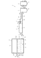
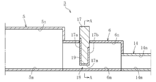
- FIG. 5 is a longitudinal sectional front view taken along line AA of FIG. 4. It is a longitudinal side view which shows the state of the principal part which is performing the preparation process in the manufacturing method of the glass article which concerns on embodiment of this invention.
- FIG. 1 illustrates a manufacturing apparatus for performing the method for manufacturing a glass article according to the present invention.
- the manufacturing apparatus 1 is roughly divided into a melting furnace 2 provided at an upstream end for heating and melting a glass material, and a molten glass Gm flowing out of the melting furnace 2 to a molding means 4.
- the apparatus includes a transfer device 3 and forming means 4 for forming the molten glass Gm supplied from the transfer device 3 into a band-shaped plate glass Gp.
- the melting furnace 2 generates the molten glass Gm by heating and melting the glass raw material, and continuously sends a predetermined amount of the molten glass Gm to the transfer device 3 while storing a large volume of the molten glass Gm.
- the transfer device 3 includes a refining tank 5, an additional tank 6 attached to the refining tank 5, a plurality of (two in the example in the figure) stirring pots 7, 8, and a cooling pipe 9 in order from the upstream side as transfer containers. , A pot 10.
- Each of these transfer containers 5 to 10 has an inlet into which the molten glass Gm flows, and an outlet through which the molten glass Gm flows out.
- the fining tank 5 is for removing bubbles in the molten glass
- an attached tank 6 is connected downstream of the fining tank 5.
- a first stirring pot 7 on the upstream side and a second stirring pot 8 on the downstream side for homogenizing the molten glass Gm are disposed downstream of the attachment tank 6.
- the stirring pots 7 and 8 accommodate stirring blades (stirrers) 7x and 8x that rotate around the axis.
- a cooling pipe 9 is arranged adjacently, and on the downstream side of the cooling pipe 9, a pot 10 is arranged adjacently as a volume part for mainly adjusting the viscosity of the molten glass Gm. Have been.
- the downstream side of the cooling pipe 9 is inclined upward.
- the forming means 4 has a formed body 11 for forming the molten glass Gm by the overflow down draw method, and a large-diameter introduction pipe 12 for guiding the molten glass Gm to the formed body 11.
- the molten glass Gm is supplied to the introduction pipe 12 from the pot 10 of the transfer device 3.
- FIG. 2 is an enlarged vertical sectional view schematically showing the melting furnace 2 and the transfer device 3 during operation.
- the melting furnace 2 supplies molten glass Gm at about 1700 ° C. by charging a glass material into an internal space surrounded by a bottom wall 2c, a side wall 2d, and an upper wall 2e. Generate.
- the bottom wall 2c and the side wall 2d include a zirconia-based refractory.
- a thin plate made of a noble metal for example, platinum or a platinum alloy
- the glass material is continuously replenished and charged into the melting furnace 2, so that the liquid level of the molten glass Gm in the melting furnace 2 is maintained substantially constant.
- the outlet 2b of the melting furnace 2 is formed below the side wall (downstream side wall) 2d.
- the outlet 2 b communicates with the inlet 5 a of the fining tank 5 via the upstream connection pipe 13.
- the outlet 5b of the fining tank 5 overlaps and communicates with the inlet 6a of the attached tank 6.
- the outlet 6b of the attachment tank 6 communicates with the inlet 7a of the first stirring pot 7 via the intermediate connection pipe 14.
- the inflow port 7a of the first stirring pot 7 is provided on the upper part of the peripheral wall.
- the outlet 7b of the first stirring pot 7 communicates with the inlet 8a of the second stirring pot 8 via the downstream connection pipe 15.
- An outlet 7b of the first stirring pot 7 is provided at a lower portion of the peripheral wall, and an inlet 8a of the second stirring pot 8 is provided at an upper portion of the peripheral wall.
- These stirring pots 7, 8 are arranged at the same height.
- the downstream connection pipe 15 has a downstream side inclined upward.
- the outlet 8b of the second stirring pot 8 overlaps and communicates with the inlet 9a of the cooling pipe 9.
- the outlet 8b of the second stirring pot 8 is provided at a lower portion of the peripheral wall.
- the downstream side of the cooling pipe 9 is inclined upward.
- the outlet 9b of the cooling pipe 9 overlaps and communicates with the inlet 10a of the pot 10.
- the pot 10 has an upper large diameter portion 10x and a lower small diameter portion 10y.
- the inlet 10a of the pot 10 is provided on the peripheral wall of the large diameter portion 10x, and the outlet 10b is provided at the lower end of the small diameter portion 10y.
- the small diameter portion 10y of the pot 10 is inserted into the introduction pipe 12 of the forming means 4. The lower end of the small diameter portion 10y is immersed in the molten glass Gm in the introduction pipe 12.
- the transfer channel composed of the transfer containers 5 to 10 and the connection pipes 13 to 15 at least a portion (in this embodiment, the entire inner surface of the transfer channel) in contact with the molten glass Gm has a thin wall thickness of platinum or platinum. It is formed of a member made of a platinum alloy. The periphery of those members is covered with a refractory (not shown).
- the transfer flow path is electrically heated so that the temperature of each transfer container 5 to 10 and each of the connection pipes 13 to 15 can be adjusted.
- the method for producing a glass article according to the present invention includes a melting step of generating molten glass Gm in the melting furnace 2 and a transfer step of transferring the molten glass Gm flowing out of the melting furnace 2 to the forming means 4 by the transfer device 3. And a forming step of forming the molten glass Gm supplied from the transfer device 3 into a predetermined shape by the forming means 4. Further, this manufacturing method includes an exchange step of exchanging the transfer device 3 while interrupting the transfer step and the forming step and holding the molten glass Gm in the melting furnace 2. Then, a preparation process is performed after the transfer device 3 is attached to the melting furnace 2 in the exchange process and before the molding process is started.
- FIG. 3 illustrates a state in which the transfer device 3 is detached (separated) from the melting furnace 2 in the replacement process.
- This replacement step is for performing a repair work on the transfer device 3.
- the molding device 4 is detached from the transfer device 3, but the molding device 4 may be attached to the transfer device 3.
- the replacement step only the transfer device 3 may be replaced, or the molding device 4 may be replaced together with the transfer device 3.
- the outflow port 2 b of the melting furnace 2 is closed by a blocking plate 16.
- the temperature of the molten glass Gm in the melting furnace 2 is maintained at a high temperature of, for example, about 1700 ° C. because the melting furnace 2 is continuously heated as in the operation. Therefore, platinum, zirconia, and the like are in a state in which the middle portion Gm1 and the lower portion Gm2 of the molten glass Gm in the melting furnace 2 are melted.
- a duct 2f is attached to a side wall (upstream side wall) 2d of the melting furnace 2, and the melting furnace 2 includes an overflow device constituted by the duct 2f.
- the upper layer portion Gm3 (cross-hatched portion) of the molten glass Gm in the melting furnace 2 is discharged outside through the duct 2f. Since the glass material is appropriately replenished into the melting furnace 2, the liquid level of the molten glass Gm in the melting furnace 2 is kept constant (for example, the liquid level during operation). By performing such a process, the molten glass Gm in the melting furnace 2 flows. This makes it difficult for the molten glass Gm to be cooked in the melting furnace 2 and suppresses an increase in the concentration of platinum, zirconia, or the like.
- a gate 17 for opening and closing the flow path and changing the degree of opening of the flow path is inserted into the attachment tank 6. More specifically, as shown in FIGS. 4 and 5, a gap 18 is provided between the lower surface 6 m of the attachment tank 6 and the bottom 16 m of the gate 17. The gap 18 is a flow path (a narrowed flow path) through which the molten glass Gm flows.
- the gate 17 is moved up and down by an elevating mechanism (not shown) to open and close the flow path and change the degree of opening of the flow path, thereby adjusting the flow rate of the molten glass Gm flowing toward the downstream side.
- a thin plate material 19 made of platinum or a platinum alloy is adhered to the front surface portion 17a and the back surface portion 17b, the side surface portions 17c, and the bottom surface portion 17m of the refractory forming the gate 17.
- the gate 17 has a U-shape from both sides 17c to the bottom 17m.
- the refining tank 5 has a pipe shape.
- the attachment tank 6 has a pipe shape, but only a portion where the gate 17 is inserted has a U shape as shown in FIG.
- the passage area of the fining tank 5 is larger than the passage area of the attachment tank 6, and the passage area of the attachment tank 6 is larger than the passage area of the intermediate connection pipe 14.
- the lowest part of the lower surface 5m of the fining tank 5, the lowest part of the lower part 6m of the attachment tank 6, and the lower part of the lower part 14m of the intermediate connection pipe 14 are at the same height position.
- the uppermost portion of the upper surface portion 5n of the refining tank 5 is higher than the uppermost portion of the upper surface portion 6n of the additional tank 6, and the uppermost portion of the upper surface portion 6n of the additional tank 6 is the highest of the upper surface portion 14n of the intermediate connection pipe 14. Higher than the top.
- FIG. 6 illustrates a state in which the transfer device 3 after the renovation work is attached to the melting furnace 2 and a preparation process is being performed.
- the preparation process is performed during the middle of the replacement process and before the molding device 4 is attached to the transfer device 3 and the molding process starts. If the molding device 4 is attached to the transfer device 3 at this time, the preparation process is executed from the end of the replacement process to the start of the molding process.
- the upper layer portion Gm of the molten glass Gm is not discharged to the outside by the overflow device described above, but may be performed.
- the molten glass Gm that has flowed out of the lower outlet 2b of the melting furnace 2 continues to flow into the transfer device 3.
- the molten glass Gm (especially the middle layer portion Gm1 and the lower layer portion Gm2) has a high concentration of platinum or the like which causes the occurrence of needle-like bumps.
- the molten glass Gm flows and flows from the upstream connection pipe 13 of the transfer device 3 to the second stirring pot 8, and settles in a retained state.
- the liquid level of the molten glass Gm in the second stirring pot 8 is lower than the inlet 9a of the cooling pipe 9, and the molten glass Gm does not flow into the cooling pipe 9.
- the liquid level of the molten glass Gm in the second stirring pot 8 may be higher than the inlet 9 a of the cooling pipe 9 so that the molten glass Gm flows into the cooling pipe 9. In the latter case, the liquid level of the molten glass Gm in the second stirring pot 8 is set lower than the outlet 9 b of the cooling pipe 9.
- the flow rate of the molten glass Gm flowing into the first and second stirring pots 7 and 8 is adjusted by the gate 17.
- the drain holes 7g and 8g of the first and second stirring pots 7 and 8 are all open to the atmosphere. Therefore, the molten glass Gm in the first and second stirring pots 7 and 8 is continuously discharged downward through the drain holes 7g and 8g.
- the flow passage area of the drain hole 7g of the first stirring pot 7 is smaller than the flow passage area of each of the inlet 7a and the outlet 7b of the first stirring pot 7.
- the flow passage area of the drain hole 8g of the second stirring pot 8 is also smaller than the flow passage area of each of the inlet 8a and the outlet 8b of the second stirring pot 8.
- This preparation process is performed until the concentration of platinum or the like contained in the molten glass Gm in the melting furnace 2 and the transfer device 3 is reduced to a level that does not cause a problem in the manufactured glass article.
- the total amount W1 (kg) of the molten glass Gm discharged from the inside of the transfer device 3 to the outside in the preparation process is equal to the total amount W2 (kg) of the molten glass Gm held in the melting furnace 2 in the replacement process.
- W1 / W2 can be, for example, 0.5 or more, and preferably 1 or more.
- W1 / W2 is preferably set to 1.5 or less.
- the melting furnace 2 of the present embodiment is a single melter having one melting space
- the melting furnace 2 may be a multi-melter in which a plurality of melting spaces are connected.
- the total amount of the molten glass Gm held in the lowermost melting space in the exchange process is W3 (Kg)
- W1 / W3 is preferably 1 or more.
- W1 / W3 is preferably set to 1.5 or less.
- the forming means 4 is attached to the transfer device 3, and the drain holes 7 g of the first and second stirring pots 7 and 8 are formed. , 8 g are closed.
- the gate 17 is detached from the attachment tank 6, and an opening for inserting and removing the gate 17 is covered with a lid member 20 made of platinum or a platinum alloy.
- the present invention is not limited to the above embodiment, and various variations are possible as exemplified below.
- the molten glass Gm is discharged from the drain holes 7g and 8g of the first and second stirring pots 7 and 8 when performing the preparation process.
- the glass Gm may be discharged.
- the gate 17 is provided in the attachment tank 6, but the flow rate may be adjusted only by adjusting the temperature of the molten glass Gm without using the gate 17.
- the location of the gate 17 may be another location as long as it is a flow path between the fining tank 5 and the first stirring pot 7.
- the gate 17 is used as a member for adjusting the flow rate of the molten glass Gm flowing through the transfer device.
- an inlet is provided on the peripheral wall and the bottom is provided.
- a structure having a container having an outlet on a wall and having a plunger for adjusting the amount of molten glass flowing out from the outlet (this structure itself is well known) is adopted, and the plunger is used as a member for adjusting the flow rate. May be used.
- the forming means 4 is for forming the band-shaped plate glass Gp, but may be for forming into another shape corresponding to the glass article.
Landscapes
- Chemical & Material Sciences (AREA)
- Engineering & Computer Science (AREA)
- Materials Engineering (AREA)
- Organic Chemistry (AREA)
- Glass Melting And Manufacturing (AREA)
Abstract
溶融ガラスGmを生成する溶融工程と、複数の移送容器5~9を含む移送装置3によって溶融ガラスGmを成形手段4まで移送する移送工程と、溶融ガラスGmを成形手段4によって所定形状に成形する成形工程と、溶融炉2に溶融ガラスGmを保有させた状態で移送装置3を交換する交換工程とを備え、交換工程で溶融炉2に移送装置3を取り付けてから成形工程を開始するまでの間に、溶融炉2から移送装置3に溶融ガラスGmを流入させつつ移送装置3から溶融ガラスGmを外部に排出させる準備処理を実行する。
Description
本発明は、ガラス物品の製造方法に係り、詳しくは、溶融炉から流出した溶融ガラスを成形手段まで移送するための移送装置を交換する交換工程を備えたガラス物品の製造方法に関する。
周知のように、ガラス物品を製造する際には、溶融炉から流出した溶融ガラスを移送装置によって成形装置に供給することが行われる。移送装置は、溶融ガラスを移送するための移送容器を有する。溶融炉は、ガラス原料を加熱溶融して移送装置に溶融ガラスを送る役割を果たす。
一例として、特許文献1には、溶融炉と、複数の移送容器を含む移送装置が開示されている。この移送容器としては、上流側から順に、清澄パイプ、攪拌ポット、冷却パイプ、及びポットなどが挙げられている。これらの移送容器を含む移送流路は、通例、稼働時に少なくとも溶融ガラスと接触する部位が、薄肉の白金または白金合金からなる部材で形成されている。
ところで、移送装置に経年劣化や故障等が生じた場合には、その移送装置の改修工事を行って改修後の移送装置と交換したり或いは新品の移送装置と交換したりすることが行われる。この際には、移送装置を一旦溶融炉から取り外し、所定期間の経過後に、改修後または新品の移送装置を溶融炉に取り付けているのが実情である。
この移送装置の交換時に、該移送装置が取り外された溶融炉を、加熱を止めてそのまま放置した場合には、溶融炉内の溶融ガラスが固形化(半固形化を含む)する。そのため、再稼働時に、固形化したガラスを溶融ガラスにするための昇温処理が長引くと共に、その昇温のための手間や労苦が増大するという問題が生じる。
この問題に対しては、移送装置が取り外された後、その交換が完了するまでの間に、溶融炉を加熱したままの状態に維持して、溶融炉に溶融ガラスを保有させておくことが考えられる。しかしながら、溶融炉を加熱したままの状態に維持しておくと、溶融炉内の溶融ガラスが炊き込まれる。溶融炉は、例えば、ジルコニア系などの耐火物を含み、その内壁面の適所に、薄肉の貴金属(例えば白金または白金合金)からなる板材が貼り付けられている。
そのため、溶融炉内では、炊き込まれた溶融ガラスに白金やジルコニアなどが溶け込む。この溶融ガラスが、再稼働時に移送装置を流れる際には、攪拌ポットで攪拌作用を受けることなどに起因して、貴金属等からなる針状の異物(以下、針状ブツという)が発生する。さらに、この溶融ガラスが、例えばオーバーフローダウンドロー法を実行する成形手段の成形体に供給された際には、成形体の壁面に針状ブツが付着する。
このような状態で、溶融炉から移送装置を通じて成形手段に供給される溶融ガラスが、成形体の両側壁面をそれぞれ流下する際には、両側壁面に付着していた針状ブツがそれぞれの溶融ガラスの接触面に転移する。そして、これらの溶融ガラスが成形体の下端で融合して得られる板ガラスには、融合の際の合わせ面に相当する部位に針状ブツが入り込んだ状態になる。この針状ブツは、欠陥であり、製品不良等の致命的な問題を招くおそれがある。しかも、針状ブツは、成形体の壁面にこびり付いた状態になるため、長期間(例えば1か月または2か月程度)を経なければ針状ブツによる製品不良等をなくすことができない。
以上の観点から、本発明は、移送装置の交換から再稼働が行われるまでの間に、成形手段に供給されるべき溶融ガラスに不当な異物が混入されないようにして、再稼働の開始時から高品位のガラス物品を製造できるようにすることを課題とする。
上記課題を解決するために創案された本発明は、溶融炉でガラス原料を加熱溶融して溶融ガラスを生成する溶融工程と、前記溶融炉で生成した溶融ガラスを移送装置によって移送する移送工程と、前記移送装置から供給された溶融ガラスを成形手段によって所定形状に成形する成形工程と、を備えたガラス物品の製造方法であって、前記移送工程及び前記成形工程を中断して、前記溶融炉に溶融ガラスを保有させた状態で、前記移送装置を交換する交換工程を有し、前記交換工程で前記溶融炉に前記移送装置を取り付けてから前記成形工程を開始するまでの間に、前記溶融炉から前記移送装置に溶融ガラスを流入させつつ該移送装置内の溶融ガラスを外部に排出させる準備処理を実行することに特徴づけられる。
このような方法によれば、移送装置の交換工程で溶融炉に移送装置を取り付けるまでの間は、溶融炉による加熱が停止されないことによって、溶融炉内では、ガラスが固形化されずに、溶融ガラスを保有した状態になる。そして、溶融炉に移送装置を取り付けた場合には、準備処理が実行されることで、溶融炉から移送装置に溶融ガラスが流入する。この溶融ガラスは、移送装置を流れ、成形手段に供給される前に移送装置から外部に排出される。この動作は、例えば、溶融炉で生成された白金等を含む溶融ガラスの全量が、完全に移送装置を通じて外部に排出されるまで行われる。そのため、成形工程の開始時には、溶融炉から移送装置を通じて成形手段に供給される溶融ガラスに、針状ブツ等の不当な異物の濃度を低下させることができる。これにより、再稼働の開始時から成形手段を通じて製造されるガラス物品に、不当な異物が入り込むのを低減できる。その結果、製品不良等の発生を未然に防止することができる。
前述の方法において、前記準備処理の実行時に、前記移送装置が備える攪拌ポットの内底面に開口するドレン孔から溶融ガラスを外部に排出させるようにしてもよい。
このようにすれば、攪拌ポットでの溶融ガラスの温度は溶融炉や清澄槽での溶融ガラスの温度よりも低いため、好適な流量で溶融ガラスを外部に排出させることができ、排出された溶融ガラスの取り扱いが容易となる。
この場合、前記移送装置は前記攪拌ポットを複数備え、前記準備処理の実行時に、全ての攪拌ポットの内底面にそれぞれ開口するドレン孔から溶融ガラスを外部に排出させることが好ましい。
このようにすれば、溶融炉で生成された白金等を含む溶融ガラスの全量を移送装置から排出させるまでの時間が短くなる。これにより、移送装置から排出される溶融ガラスの流量調整を適正に行いながら、溶融ガラスの排出を効率良く行うことができる。
前述の方法において、前記移送装置は、前記撹拌ポットより上流側に配置される清澄槽と、前記清澄槽と前記撹拌ポットの間に配置されるゲートとを備え、前記準備工程の実行時に、前記ゲートによって前記移送装置の流路の開度を変更することによって前記溶融ガラスの流量を調整することが好ましい。
ここで、熔融炉や清澄槽、撹拌ポット内の溶融ガラスの温度をそれぞれ変更することによって移送装置内から外部に排出する溶融ガラスの流量を調整することもできるが、準備処理の溶融ガラスの温度と操業時の温度との乖離が大きいと、準備処理の完了後に溶融ガラスの温度調整に時間を要する。このため、溶融ガラスの温度による流量調整には限界がある。ここでの方法では、ゲートで流路の開度を変更することによって溶融ガラスの流量を調整することから、熔融炉や清澄槽内の溶融ガラスの温度を所望の温度に維持した状態で、簡便に流量調整をすることが可能になる。
以上の方法において、前記交換工程を開始してから前記準備処理を開始するまでの間に、前記溶融炉の溶融ガラスの上層部分を、前記溶融炉が備えるオーバーフロー装置によって外部に排出させるようにしてもよい。
ここで、交換工程を開始してから準備処理を開始するまでの間は、溶融炉から移送装置が取り外されているため、溶融炉内の溶融ガラスが炊き込まれた状態になり得る。しかし、ここでの方法では、溶融炉の溶融ガラスの上層部分がオーバーフロー装置によって外部に排出されるため、溶融ガラスに流動が生じる。これにより、溶融炉内で溶融ガラスが炊き込まれ難くなって、白金等の濃度の上昇を抑えることができる。なお、溶融炉から溶融ガラスの上層部分を外部に排出させる際には、溶融炉にガラス原料を適宜補充して、溶融炉内での溶融ガラスの液面高さを一定に維持しておくことが好ましい。
以上の方法において、前記準備処理の実行時に、前記溶融炉の溶融ガラスを、前記オーバーフロー装置によるオーバーフロー部位よりも下側から前記移送装置に流入させつつ該移送装置から外部に排出させるようにすることが好ましい。
ここで、前述のようにオーバーフロー装置によって溶融炉から溶融ガラスの上層部分を溢れ出させても、溶融ガラスの中層部分や下層部分には、白金やジルコニア等の異物が残ったままの状態になり得る。しかし、ここでの方法では、準備処理の実行時に、溶融炉のオーバーフロー部位よりも下側から溶融ガラスを移送装置に流入させつつ外部に排出させるようにしている。これにより、白金等の異物が残留し得る溶融ガラスの中層部分と下層部分とを、移送装置に流入させた後、外部に排出させることができる。
以上の方法において、前記溶融炉が溶融空間を一つ備えるシングルメルターである場合、前記準備処理で前記移送装置内から外部に排出する溶融ガラスの総量W1(kg)は、前記交換工程で前記溶融炉に保有された溶融ガラスの全量W2(kg)に対する比(W1/W2)で、1以上であることが好ましい。また、溶融炉が複数の溶融空間が連なるマルチメルターである場合、前記準備処理で前記移送装置内から外部に排出する溶融ガラスの総量W1(kg)は、前記交換工程で前記複数の溶融空間の内で最下流に位置する溶融空間に保有された溶融ガラスの全量W3(kg)に対する比(W1/W3)で、1以上であることが好ましい。
このようにすれば、溶融炉に溜められていた溶融ガラスの大部分が、移送装置から外部に排出される。これにより、溶融炉に溜められていて白金等の濃度が上昇した溶融ガラスが、成形手段に供給されるのを防止できる。
本発明によれば、移送装置の交換から再稼働が行われるまでの間に、成形手段に供給されるべき溶融ガラスの不当な異物の濃度を低下させることができ、再稼働の開始時から高品位のガラス物品を製造することが可能になる。
以下、本発明の実施形態に係るガラス物品の製造方法について添付図面を参照しつつ説明する。
図1は、本発明に係るガラス物品の製造方法を実施するための製造装置を例示している。同図に示すように、この製造装置1は、大別すると、上流端に配備されてガラス原料を加熱溶融する溶融炉2と、溶融炉2から流出した溶融ガラスGmを成形手段4まで移送する移送装置3と、移送装置3から供給される溶融ガラスGmを帯状の板ガラスGpに成形する成形手段4とを備える。
溶融炉2は、ガラス原料を加熱溶融することによって溶融ガラスGmを生成し、大容量の溶融ガラスGmを溜めながら、移送装置3に所定量の溶融ガラスGmを送り続ける。
移送装置3は、移送容器として上流側から順に、清澄槽5と、清澄槽5に付設された付設槽6と、複数(図例では2個)の攪拌ポット7、8と、冷却パイプ9と、ポット10とを有する。これらの移送容器5~10はそれぞれ、溶融ガラスGmが流入する流入口と、溶融ガラスGmが流出する流出口とを備えている。
詳述すると、清澄槽5は、溶融ガラス中の気泡を除去するもので、清澄槽5の下流側には、付設槽6が接続されている。付設槽6の下流側には、溶融ガラスGmを均質化させる上流側の第1攪拌ポット7と下流側の第2攪拌ポット8とが配設されている。製造装置1の稼働時における各攪拌ポット7、8には、軸心廻りに回転する攪拌羽根(スターラー)7x、8xがそれぞれ収容されている。第2攪拌ポット8の下流側には、冷却パイプ9が隣接して配置され、冷却パイプ9の下流側には、溶融ガラスGmの粘度調整を主として行う容積部としてのポット10が隣接して配置されている。冷却パイプ9は、下流側が上方に向かって傾斜している。
成形手段4は、オーバーフローダウンドロー法により溶融ガラスGmを成形する成形体11と、成形体11に溶融ガラスGmを導く大径の導入パイプ12とを有する。導入パイプ12には、移送装置3のポット10から溶融ガラスGmが供給されるようになっている。
図2は、稼働時における溶融炉2及び移送装置3を簡略的に示す拡大縦断面図である。
同図に示すように、溶融炉2は、底壁部2cと側壁部2dと上壁部2eとで囲まれた内部空間に、ガラス原料を投入することで、1700℃程度の溶融ガラスGmを生成する。底壁部2cと側壁部2dとは、ジルコニア系の耐火物を含む。溶融炉2の側壁部2dのうちで流出口2b及びその周辺には、貴金属(例えば白金または白金合金)からなる薄肉の板材が貼り付けられている(図示なし)。溶融炉2からは、移送装置3に単位時間当たり一定量の溶融ガラスGmが連続的に送給される。溶融炉2には、ガラス原料が連続的に補充して投入されることで、溶融炉2内の溶融ガラスGmの液面高さは略一定に維持される。
溶融炉2の流出口2bは、その側壁部(下流側の側壁部)2dの下部に形成されている。この流出口2bは、上流側接続パイプ13を介して、清澄槽5の流入口5aに連通している。清澄槽5の流出口5bは、付設槽6の流入口6aと重なり合って連通している。付設槽6の流出口6bは、中間接続パイプ14を介して、第1攪拌ポット7の流入口7aに連通している。第1攪拌ポット7の流入口7aは、その周壁の上部に設けられている。第1攪拌ポット7の流出口7bは、下流側接続パイプ15を介して、第2攪拌ポット8の流入口8aに連通している。第1攪拌ポット7の流出口7bは、その周壁の下部に設けられ、第2攪拌ポット8の流入口8aは、その周壁の上部に設けられている。これらの攪拌ポット7、8は、同一高さに配置されている。下流側接続パイプ15は、下流側が上方に向かって傾斜している。第2攪拌ポット8の流出口8bは、冷却パイプ9の流入口9aと重なり合って連通している。第2攪拌ポット8の流出口8bは、その周壁の下部に設けられている。冷却パイプ9は、下流側が上方に向かって傾斜している。冷却パイプ9の流出口9bは、ポット10の流入口10aと重なり合って連通している。ポット10は、上方の大径部10xと下方の小径部10yとを有する。ポット10の流入口10aは、大径部10xの周壁に設けられ、流出口10bは、小径部10yの下端に設けられている。ポット10の小径部10yは、成形手段4の導入パイプ12に挿入されている。小径部10yの下端部は、導入パイプ12内の溶融ガラスGm中に浸漬している。
上記の各移送容器5~10及び各接続パイプ13~15で構成される移送流路は、少なくとも溶融ガラスGmと接触する部位(この実施形態では移送流路の内面全域)が、薄肉の白金または白金合金からなる部材で形成されている。それらの部材の周囲は、図外の耐火物で覆われている。移送流路は、通電加熱されており、各移送容器5~10及び各接続パイプ13~15ごとに温度調整することが可能になっている。
以上の構成を備えた製造装置1は、次に示すような工程を実行する。すなわち、本発明に係るガラス物品の製造方法は、溶融炉2で溶融ガラスGmを生成する溶融工程と、溶融炉2から流出した溶融ガラスGmを移送装置3によって成形手段4まで移送する移送工程と、移送装置3から供給された溶融ガラスGmを成形手段4によって所定形状に成形する成形工程とを備える。さらに、この製造方法は、移送工程および成形工程を中断して、溶融炉2に溶融ガラスGmを保有させた状態で、移送装置3を交換する交換工程を備える。そして、交換工程で溶融炉2に移送装置3を取り付けてから、成形工程を開始するまでの間に、準備処理が実行される。
図3は、交換工程で、溶融炉2から移送装置3が取り外されている(切り離されている)状態を例示している。この交換工程は、移送装置3の改修工事を行うためのものである。なお、この実施形態では、移送装置3から成形手段4が取り外されているが、移送装置3に成形手段4が取り付けられていてもよい。また、交換工程では、移送装置3のみを交換してもよく、移送装置3と共に成形手段4を交換してもよい。
同図に示すように、溶融炉2の流出口2bは、遮断板16で閉鎖されている。溶融炉2は、稼働時と同様に加熱され続けているため、溶融炉2内の溶融ガラスGmの温度は、例えば1700℃程度の高温に維持されている。そのため、溶融炉2内の溶融ガラスGmの中層部分Gm1と下層部分Gm2とには、白金やジルコニア等が溶け込んだ状態にある。
溶融炉2の側壁(上流側の側壁)2dには、ダクト2fが装着されており、溶融炉2は、ダクト2fによって構成されるオーバーフロー装置を備える。溶融炉2内の溶融ガラスGmの上層部分Gm3(クロスハッチングを付した部分)は、ダクト2fを通じて外部に排出される。溶融炉2には、ガラス原料が適宜補充されるため、溶融炉2内での溶融ガラスGmの液面高さは一定(例えば操業時の液面高さ)に維持される。このような処理が行われることによって、溶融炉2内の溶融ガラスGmに流動が生じる。これにより、溶融炉2内で溶融ガラスGmが炊き込まれ難くなって、白金やジルコニア等の濃度の上昇が抑えられる。
移送装置3は、各移送容器5~10及び各接続パイプ13~15の全てが空の状態になっている。これらのうち、第1、第2攪拌ポット7、8からは、攪拌羽根7x、8xが抜き取られている。付設槽6には、流路を開閉及び流路の開度を変更するためのゲート17が挿入されている。詳述すると、図4及び図5に示すように、付設槽6の下面部6mと、ゲート17の底面部16mとの間には、隙間18が設けられている。この隙間18は、溶融ガラスGmが流れる流路(狭くされた流路)である。ゲート17は、図外の昇降機構によって上下動することによって、流路を開閉及び流路の開度を変更し、下流側に向かって流れる溶融ガラスGmの流量調整を行う。ゲート17を形成している耐火物の表面部17a及び裏面部17bと、両側面部17cと、底面部17mとには、白金または白金合金からなる薄肉の板材19が貼り付けられている。ゲート17は、両側面部17cから底面部17mにかけてU字形状をなす。
清澄槽5は、パイプ形状をなす。付設槽6は、パイプ形状をなすが、ゲート17が挿入される部位のみが図5に示すようにU字形状をなす。清澄槽5の流路面積は、付設槽6の流路面積よりも大きく、付設槽6の流路面積は、中間接続パイプ14の流路面積よりも大きい。詳しくは、清澄槽5の下面部5mの最低部と、付設槽6の下面部6mの最低部と、中間接続パイプ14の下面部14mの最低部とは、同一高さ位置にある。そして、清澄槽5の上面部5nの最上部は、付設槽6の上面部6nの最上部よりも高く、付設槽6の上面部6nの最上部は、中間接続パイプ14の上面部14nの最上部よりも高い。
図6は、改修工事を終えた移送装置3を溶融炉2に取り付けて、準備処理を実行している状態を例示している。この実施形態では、準備処理は、交換工程の途中から、移送装置3に成形手段4が取り付けられて成形工程が開始するまでの間に実行される。なお、この時点で移送装置3に成形手段4が取り付けられている場合には、準備処理は、交換工程の終了時から成形工程が開始するまでの間に実行される。また、この実施形態では、準備処理を実行している間は、既述のオーバーフロー装置によって溶融ガラスGmの上層部分Gmを外部へ排出することを行っていないが、行ってもよい。
同図に示すように、溶融炉2の下部の流出口2bから流出した溶融ガラスGmは、移送装置3に流入し続ける。この溶融ガラスGm(特に中層部分Gm1と下層部分Gm2)には、針状ブツの発生原因となる白金等の濃度が高い。そして、図示のように、この溶融ガラスGmは、移送装置3の上流側接続パイプ13から第2攪拌ポット8までの部位で流動しつつ保有された状態に落ち着く。なお、本実施形態の準備処理では、第2攪拌ポット8の溶融ガラスGmの液面高さが冷却パイプ9の流入口9aよりも低く、溶融ガラスGmが冷却パイプ9に流入していないが、第2攪拌ポット8の溶融ガラスGmの液面高さを冷却パイプ9の流入口9aよりも高くし、溶融ガラスGmを冷却パイプ9に流入させてもよい。後者の場合、第2攪拌ポット8の溶融ガラスGmの液面高さは、冷却パイプ9の流出口9bよりも低くする。
準備処理では、ゲート17によって第1、第2攪拌ポット7、8に流入する溶融ガラスGmの流量が調整される。第1、第2攪拌ポット7、8のドレン孔7g、8gは、何れも大気に開放されている。そのため、第1、第2攪拌ポット7、8内の溶融ガラスGmは、ドレン孔7g、8gを通じて下方に排出され続ける。
第1攪拌ポット7のドレン孔7gの流路面積は、第1攪拌ポット7の流入口7a及び流出口7bのそれぞれの流路面積よりも小さい。また、第2攪拌ポット8のドレン孔8gの流路面積も、第2攪拌ポット8の流入口8a及び流出口8bのそれぞれの流路面積よりも小さい。これにより、第1、第2攪拌ポット7、8のドレン孔7g、8gから排出される溶融ガラスGmの流量がより好適となる。さらに、二個の攪拌ポット7,8のドレン孔7g、8gから同時に溶融ガラスGmが排出されるため、その排出に要する時間が短縮される。
この準備処理は、溶融炉2及び移送装置3内の溶融ガラスGmに含まれる白金等の濃度が、製造されたガラス物品で問題とならない程度まで低下するまで行われる。本実施形態では、準備処理で移送装置3内から外部に排出する溶融ガラスGmの総量W1(kg)は、交換工程で溶融炉2に保有された溶融ガラスGmの全量W2(kg)と等しい。これにより、溶融炉2に溜まっていて針状ブツの発生要因となる白金等の濃度が上昇した溶融ガラスGmの大部分が、移送装置3を通じて外部に排出される。その結果、溶融炉2及び移送装置3には、針状ブツの発生要因となる白金等の濃度が上昇した溶融ガラスGmがほとんど残存していない状態になる。溶融炉2及び移送装置3内の溶融ガラスGmに含まれる白金等の濃度を低下させる観点では、W1/W2は、例えば0.5以上にすることができ、1以上とすることが好ましい。一方、溶融ガラスGmの排出による製造コストの増大を防止する観点から、W1/W2は1.5以下とすることが好ましい。
本実施形態の溶融炉2は、溶融空間を一つ備えるシングルメルターであるが、溶融炉2は、複数の溶融空間が連なるマルチメルターであってもよい。マルチメルターである場合、溶融炉2及び移送装置3内の溶融ガラスGmに含まれる白金等の濃度を低下させる観点では、交換工程で最下流の溶融空間に保有された溶融ガラスGmの全量をW3(kg)とすれば、W1/W3を1以上とすることが好ましい。一方、溶融ガラスGmの排出による製造コストの増大を防止する観点から、W1/W3は1.5以下とすることが好ましい。
この後、移送工程及び成形工程を開始する際には、図1及び図2に示すように、成形手段4が移送装置3に取り付けられ、第1、第2攪拌ポット7、8のドレン孔7g、8gが閉鎖される。また、この際には、付設槽6からゲート17が取り外され、このゲート17を挿脱するための開口部は、白金または白金合金からなる蓋部材20で覆われる。
また、移送工程及び成形工程を開始する際に溶融炉2及び移送装置3内に存在する溶融ガラスGmは、針状ブツの発生要因となる白金等の濃度が低下されている。これにより、成形工程の開始時から製造装置1によって製造されるガラス板に針状ブツ等が入り込むのを低減でき、製品不良等の発生を未然に防止することができる。
本発明は、上記実施形態に限定されるものではなく、以下に例示するように種々のバリエーションが可能である。
上記実施形態では、準備処理を実行する際に、第1、第2攪拌ポット7、8のドレン孔7g、8gから溶融ガラスGmを排出させるようにしたが、移送装置3の他の部位から溶融ガラスGmを排出させるようにしてもよい。
上記実施形態では、2個の攪拌ポット7、8を有する場合を例示したが、3個以上の攪拌ポットを有する場合であっても、同様にして本発明を適用することができる。この場合には、準備処理を実行する際に3個以上の攪拌ポットの全てのドレン孔から溶融ガラスGmを排出させることが好ましい。
上記実施形態では、ゲート17を付設槽6に配設したが、ゲート17を用いることなく、溶融ガラスGmの温度調整のみで流量調整を行ってもよい。また、ゲート17の配設箇所は、清澄槽5と第1攪拌ポット7との間の流路であれば、他の箇所であってもよい。
上記実施形態では、移送装置を流れる溶融ガラスGmの流量調整用の部材としてゲート17を用いたが、例えば清澄槽5と第1攪拌ポット7との間に、周壁に流入口を有し且つ底壁に流出口を有する容器を配設し、流出口からの溶融ガラスの流出量を調整するプランジャを備えた構成(この構成自体は周知である)を採用して、プランジャを流量調整用の部材として用いてもよい。
上記実施形態では、成形手段4が、帯状の板ガラスGpを成形するものであるが、ガラス物品に対応した他の形状に成形するものであってもよい。
1 製造装置
2 溶融炉
2b 流出口
2f ダクト(オーバーフロー装置)
3 移送装置
4 成形手段
5 清澄槽
6 付設槽
7 攪拌ポット
7g ドレン孔
8 攪拌ポット
8g ドレン孔
9 冷却パイプ
11 成形体
2 溶融炉
2b 流出口
2f ダクト(オーバーフロー装置)
3 移送装置
4 成形手段
5 清澄槽
6 付設槽
7 攪拌ポット
7g ドレン孔
8 攪拌ポット
8g ドレン孔
9 冷却パイプ
11 成形体
Claims (8)
- 溶融炉でガラス原料を加熱溶融して溶融ガラスを生成する溶融工程と、前記溶融炉で生成した溶融ガラスを移送装置によって成形手段まで移送する移送工程と、前記移送装置から供給された溶融ガラスを前記成形手段によって所定形状に成形する成形工程と、を備えたガラス物品の製造方法であって、
前記移送工程及び前記成形工程を中断して、前記溶融炉に溶融ガラスを保有させた状態で、前記移送装置を交換する交換工程を有し、
前記交換工程で前記溶融炉に前記移送装置を取り付けてから前記成形工程を開始するまでの間に、前記溶融炉から前記移送装置に溶融ガラスを流入させつつ該移送装置内の溶融ガラスを外部に排出させる準備処理を実行することを特徴とするガラス物品の製造方法。 - 前記準備処理の実行時に、前記移送装置が備える攪拌ポットの内底面に開口するドレン孔から溶融ガラスを外部に排出させることを特徴とする請求項1に記載のガラス物品の製造方法。
- 前記移送装置は前記攪拌ポットを複数備え、前記準備処理の実行時に、全ての攪拌ポットの内底面にそれぞれ開口するドレン孔から溶融ガラスを外部に排出させることを特徴とする請求項2に記載のガラス物品の製造方法。
- 前記移送装置は、前記撹拌ポットより上流側に配置される清澄槽と、前記清澄槽と前記撹拌ポットの間に配置されるゲートとを備え、
前記準備工程の実行時に、前記ゲートによって前記移送装置の流路の開度を変更することによって前記溶融ガラスの流量を調整することを特徴とする請求項3に記載のガラス物品の製造方法。 - 前記交換工程を開始してから前記準備処理を開始するまでの間に、前記溶融炉の溶融ガラスの上層部分を、前記溶融炉が備えるオーバーフロー装置によって外部に排出させることを特徴とする請求項1~4の何れかに記載のガラス物品の製造方法。
- 前記準備処理の実行時に、前記溶融炉の溶融ガラスを、前記オーバーフロー装置によるオーバーフロー部位よりも下側から前記移送装置に流入させることを特徴とする請求項5に記載のガラス物品の製造方法。
- 前記溶融炉は、溶融空間を一つ備えるシングルメルターであり、
前記準備処理で前記移送装置内から外部に排出する溶融ガラスの総量W1(kg)は、前記交換工程で前記溶融炉に保有された溶融ガラスの全量W2(kg)に対する比(W1/W2)で、1以上であることを特徴とする請求項1~6の何れかに記載のガラス物品の
製造方法。 - 前記溶融炉は、複数の溶融空間が連なるマルチメルターであり、
前記準備処理で前記移送装置内から外部に排出する溶融ガラスの総量W1(kg)は、前記交換工程で前記複数の溶融空間の内で最下流に位置する溶融空間に保有された溶融ガラスの全量W3(kg)に対する比(W1/W3)で、1以上であることを特徴とする請求項1~6の何れかに記載のガラス物品の製造方法。
Applications Claiming Priority (2)
| Application Number | Priority Date | Filing Date | Title |
|---|---|---|---|
| JP2018127550A JP7063153B2 (ja) | 2018-07-04 | 2018-07-04 | ガラス物品の製造方法 |
| JP2018-127550 | 2018-07-04 |
Publications (1)
| Publication Number | Publication Date |
|---|---|
| WO2020008841A1 true WO2020008841A1 (ja) | 2020-01-09 |
Family
ID=69059558
Family Applications (1)
| Application Number | Title | Priority Date | Filing Date |
|---|---|---|---|
| PCT/JP2019/023753 Ceased WO2020008841A1 (ja) | 2018-07-04 | 2019-06-14 | ガラス物品の製造方法 |
Country Status (2)
| Country | Link |
|---|---|
| JP (1) | JP7063153B2 (ja) |
| WO (1) | WO2020008841A1 (ja) |
Cited By (1)
| Publication number | Priority date | Publication date | Assignee | Title |
|---|---|---|---|---|
| CN115380011A (zh) * | 2020-04-14 | 2022-11-22 | 日本电气硝子株式会社 | 玻璃物品的制造方法以及玻璃物品的制造装置 |
Families Citing this family (1)
| Publication number | Priority date | Publication date | Assignee | Title |
|---|---|---|---|---|
| CN114057389A (zh) * | 2021-12-17 | 2022-02-18 | 江苏正威新材料股份有限公司 | 一种点供式池窑拉丝装置及其工艺方法 |
Citations (3)
| Publication number | Priority date | Publication date | Assignee | Title |
|---|---|---|---|---|
| JPH11130445A (ja) * | 1997-10-31 | 1999-05-18 | Canon Inc | ガラス流出方法および装置 |
| WO2011010624A1 (ja) * | 2009-07-24 | 2011-01-27 | 旭硝子株式会社 | ガラス製造装置及びガラス製造方法 |
| WO2013073059A1 (ja) * | 2011-11-18 | 2013-05-23 | AvanStrate株式会社 | ガラスの製造方法、および、攪拌装置 |
Family Cites Families (1)
| Publication number | Priority date | Publication date | Assignee | Title |
|---|---|---|---|---|
| JP2014094843A (ja) * | 2012-11-07 | 2014-05-22 | Nippon Electric Glass Co Ltd | 溶融ガラス移送装置 |
-
2018
- 2018-07-04 JP JP2018127550A patent/JP7063153B2/ja active Active
-
2019
- 2019-06-14 WO PCT/JP2019/023753 patent/WO2020008841A1/ja not_active Ceased
Patent Citations (3)
| Publication number | Priority date | Publication date | Assignee | Title |
|---|---|---|---|---|
| JPH11130445A (ja) * | 1997-10-31 | 1999-05-18 | Canon Inc | ガラス流出方法および装置 |
| WO2011010624A1 (ja) * | 2009-07-24 | 2011-01-27 | 旭硝子株式会社 | ガラス製造装置及びガラス製造方法 |
| WO2013073059A1 (ja) * | 2011-11-18 | 2013-05-23 | AvanStrate株式会社 | ガラスの製造方法、および、攪拌装置 |
Cited By (2)
| Publication number | Priority date | Publication date | Assignee | Title |
|---|---|---|---|---|
| CN115380011A (zh) * | 2020-04-14 | 2022-11-22 | 日本电气硝子株式会社 | 玻璃物品的制造方法以及玻璃物品的制造装置 |
| CN115380011B (zh) * | 2020-04-14 | 2024-07-12 | 日本电气硝子株式会社 | 玻璃物品的制造方法以及玻璃物品的制造装置 |
Also Published As
| Publication number | Publication date |
|---|---|
| JP2020007174A (ja) | 2020-01-16 |
| JP7063153B2 (ja) | 2022-05-09 |
Similar Documents
| Publication | Publication Date | Title |
|---|---|---|
| TWI388519B (zh) | 等管材料除氣 | |
| JPWO2020009143A1 (ja) | ガラス物品の製造方法、製造装置及びガラス基板 | |
| KR101306065B1 (ko) | 용융 유리 공급 장치 및 유리 성형품의 제조 방법 | |
| JP5520309B2 (ja) | 停滞している溶融材料の流動化 | |
| JP7063153B2 (ja) | ガラス物品の製造方法 | |
| CN115124219B (zh) | 一种消除玻璃缺陷的方法 | |
| JP7138843B2 (ja) | ガラス物品の製造方法 | |
| CN106145614A (zh) | 玻璃液的料道装置 | |
| CN112135800B (zh) | 玻璃物品的制造方法 | |
| CN101045601B (zh) | 熔解装置 | |
| JP4793581B2 (ja) | 溶融ガラス供給装置及びガラス成形品の製造方法 | |
| JP2007204357A (ja) | 溶融ガラス供給装置及びガラス成形品の製造方法 | |
| JPH11130445A (ja) | ガラス流出方法および装置 | |
| JP4148341B2 (ja) | ガラスの溶解方法、その溶解装置およびガラス成形品の製造方法 | |
| JP2026026699A (ja) | ガラス物品の製造方法及びガラス物品の製造装置 | |
| WO2023100688A1 (ja) | ガラス物品の製造方法 | |
| JP4811791B2 (ja) | 溶融ガラス供給装置及びガラス成形品の製造方法 | |
| WO2024038740A1 (ja) | ガラス物品の製造方法及びガラス物品の製造装置 | |
| JP2021195289A (ja) | ガラス物品の製造方法 | |
| JPH08188423A (ja) | ガラス溶融供給方法および装置 | |
| WO2024219246A1 (ja) | 清澄装置、ガラス物品の製造方法、及び管状部材 | |
| JP4385638B2 (ja) | 連続鋳造方法 | |
| JP2025144012A (ja) | 減圧脱泡装置及びガラス製造装置 | |
| JP2003073130A (ja) | ガラス溶融炉の流出装置 | |
| JP2010235446A (ja) | ガラス成形品の製造方法 |
Legal Events
| Date | Code | Title | Description |
|---|---|---|---|
| 121 | Ep: the epo has been informed by wipo that ep was designated in this application |
Ref document number: 19830525 Country of ref document: EP Kind code of ref document: A1 |
|
| NENP | Non-entry into the national phase |
Ref country code: DE |
|
| 122 | Ep: pct application non-entry in european phase |
Ref document number: 19830525 Country of ref document: EP Kind code of ref document: A1 |