WO2020008602A1 - 垂直多関節ロボットおよび作業装置 - Google Patents
垂直多関節ロボットおよび作業装置 Download PDFInfo
- Publication number
- WO2020008602A1 WO2020008602A1 PCT/JP2018/025570 JP2018025570W WO2020008602A1 WO 2020008602 A1 WO2020008602 A1 WO 2020008602A1 JP 2018025570 W JP2018025570 W JP 2018025570W WO 2020008602 A1 WO2020008602 A1 WO 2020008602A1
- Authority
- WO
- WIPO (PCT)
- Prior art keywords
- tool
- articulated robot
- arm
- vertical articulated
- attached
- Prior art date
- Legal status (The legal status is an assumption and is not a legal conclusion. Google has not performed a legal analysis and makes no representation as to the accuracy of the status listed.)
- Ceased
Links
Images



Classifications
-
- B—PERFORMING OPERATIONS; TRANSPORTING
- B25—HAND TOOLS; PORTABLE POWER-DRIVEN TOOLS; MANIPULATORS
- B25J—MANIPULATORS; CHAMBERS PROVIDED WITH MANIPULATION DEVICES
- B25J15/00—Gripping heads and other end effectors
-
- B—PERFORMING OPERATIONS; TRANSPORTING
- B25—HAND TOOLS; PORTABLE POWER-DRIVEN TOOLS; MANIPULATORS
- B25J—MANIPULATORS; CHAMBERS PROVIDED WITH MANIPULATION DEVICES
- B25J9/00—Program-controlled manipulators
- B25J9/06—Program-controlled manipulators characterised by multi-articulated arms
Definitions
- This specification discloses a vertical articulated robot and a working device.
- a horizontal articulated robot provided with a plurality of arms that rotate horizontally has been known.
- a first arm rotatably provided on a base
- a second arm rotatably provided on the first arm
- a second arm penetrating vertically There is disclosed a horizontal articulated robot having a main shaft provided so as to be rotatable and vertically movably supported, and a tool (such as a hand for conveying an object to be conveyed) attached to a lower end of the main shaft.
- the height in the vertical direction during use (at least one of the vertical distance from the workpiece and the vertical position based on the arm to which the tool is attached) differs depending on the tool. Therefore, when a plurality of tools having different heights in use are attached to the lower end of the spindle, the height in use of one tool may be inappropriate. Such a problem can also occur in a vertical articulated robot having a plurality of arms that pivot vertically.
- the present disclosure has a main object to provide a vertical articulated robot suitable for mounting two tools having at least one of a tool height and a height at the time of use thereof different from each other.
- the present disclosure employs the following means to achieve the above-described main object.
- the vertical articulated robot of the present disclosure A base, A plurality of arms including a proximal arm attached to the base and a distal arm opposite to the proximal arm, wherein adjacent arms are vertically rotatably connected to each other, A first tool holding portion disposed on a longitudinal end surface of the tip arm and to which a first tool for performing an operation on a workpiece is attached; A second tool holding portion disposed on a longitudinal side surface of the tip arm, to which a second tool for performing an operation on a workpiece is attached;
- the gist is to provide
- the first tool holding unit is disposed on the longitudinal end surface of the distal arm
- the second tool holding unit is disposed on the longitudinal side surface of the distal arm.
- the one with the lower height when used is attached to the first tool holding portion as the first tool, and the one with the higher height when used is the second tool.
- the vertical articulated robot can be made suitable for mounting two tools having different tool heights and / or different heights during use.
- the term “vertical” is not limited to a completely vertical one, but it is sufficient if the vertical is substantially vertical.
- the “first tool” and the “second tool” may perform operations on the same work, or may perform operations on different works.
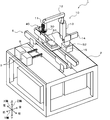
- FIG. 1 is a schematic configuration diagram of a working device 1.
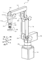
- FIG. 2 is a schematic configuration diagram of a working robot in which a first tool unit is attached to a distal arm.
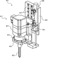
- FIG. 2 is a schematic configuration diagram of a second tool unit 40.
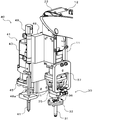
- FIG. 4 is a partially enlarged view of the work robot 10 in which first and second tool units 30 and 40 are attached to a distal arm 11 as viewed from the front.
- FIG. 4 is a partially enlarged view of the working robot 10 in which first and second tool units 30 and 40 are attached to a distal arm 11 as viewed from the rear.
- FIG. 9 is an explanatory diagram illustrating a moving range of a second tool.
- FIG. 2 is a block diagram illustrating an electrical connection relationship of the working device 1. It is a schematic structure figure of the 2nd tool unit 140 of a modification.
- FIG. 1 is a schematic configuration diagram of the working device 1.
- FIG. 2 is a schematic configuration diagram of the working robot 10 in which the first tool unit 30 is attached to the distal arm 11.
- FIG. 3 is a schematic configuration diagram of the second tool unit 40.
- FIG. 4 is a partially enlarged view of the working robot 10 in which the first and second tool units 30 and 40 are attached to the distal arm 11 as viewed from the front.
- FIG. 5 is a partially enlarged view of the working robot 10 in which the first and second tool units 30 and 40 are attached to the distal arm 11 as viewed from the rear.
- FIG. 6 is an explanatory diagram illustrating a moving range of the second tool.
- FIG. 7 is a block diagram illustrating an electrical connection relationship of the working device 1. 1 and 2, the left-right direction is the X direction, the front-rear direction is the Y direction, and the up-down direction is the Z direction.
- the working device 1 of the embodiment performs a predetermined work on a workpiece using a vertical articulated robot.
- the work device 1 includes a pedestal 2, a supply device 3, a transfer device 5, a work robot 10, and a control device 50 (see FIG. 7) for controlling the whole.
- the working device 1 is configured as, for example, a fastening device that picks up a bolt and fastens the picked-up bolt to a member to be fastened to fasten the fastening member and the member to be fastened.
- a fastening device that picks up a bolt and fastens the picked-up bolt to a member to be fastened to fasten the fastening member and the member to be fastened.
- the supply device 3 is a screw feeder that arranges a large number of male screws B placed in a hopper separately with their screw heads facing upward and supplies the aligned male screws B one by one.
- the transport device 5 is a belt conveyor device, and transports the member S2 having a screw hole on the upper surface thereof in a state where the member S2 is overlapped with the fastening member S1.
- the transport device 5 is installed at the center of the pedestal 2 in the Y direction so as to extend in the X direction.
- the supply device 3 is installed on the pedestal 2 in front of the transport device 5.
- the working robot 10 is a vertical articulated robot.
- the work robot 10 is installed on the pedestal 2 on the side opposite to the supply device 3 with the transfer device 5 interposed therebetween.
- the work robot 10 includes a plurality of arms (a distal arm 11, intermediate arms 12, 13 and a proximal arm 14) connected in series, a base 15, a plurality of joints 21 to 25, and And motors 21a to 25a for driving the joints 21 to 25 (see FIG. 7), and encoders 21b to 25b for detecting the rotation angles of the joints 21 to 25 (see FIG. 7).
- the base arm 14 is attached to the base 15 via a joint 25 so as to be horizontally pivotable.
- the distal arm 11, the intermediate arms 12, 13 and the proximal arm 14 are vertically rotatably connected via corresponding joints 22 to 24, respectively.
- the distal arm 11 has a joint (also referred to as a wrist) 21 rotatable around an axis along the longitudinal direction at a longitudinal distal end portion.
- Two tool units (a first tool unit 30 and a second tool unit 40) are attached to the tip arm 11 as end effector devices.
- the first tool unit 30 is disposed on the longitudinal end surface (end surface) of the end arm 11, as shown in FIG.
- the first tool unit 30 includes a first tool 31 and a first tool holder 35 fixed to the wrist 21 of the distal arm 11.
- the first tool 31 is a suction nozzle in the present embodiment, and has a cylindrical nozzle body 32 and a flange 33 extending radially from an upper end of the nozzle body 32.
- the nozzle body 32 is supplied with a negative pressure from a negative pressure source (not shown) at its tip, and sucks a male screw B as a workpiece by the negative pressure.
- the first tool holding portion 35 has a flange portion 36 at a tip portion (a lower end portion in the figure).
- the first tool 31 is held by the first tool holding portion 35 by being fixed with screws or the like in a state where the flange portion 33 abuts against the flange portion 36 of the first tool holding portion 35.
- the first tool 31 is held so that the tip of the nozzle body 32 faces downward (directly downward) when the tip arm 11 points downward (directly downward). Further, the first tool 31 (nozzle main body 32) rotates together with the first tool holding unit 35 by the rotation of the wrist 21 because the first tool holding unit 35 is attached to the wrist 21 of the distal end arm 11.
- the second tool unit 40 is disposed on the front side surface 11 s of the longitudinal side surfaces of the distal end arm 11 as shown in FIG. 4.
- the second tool unit 40 includes a second tool 41, a second tool holding unit 45, a second tool lifting / lowering device 48, and a unit mounting member 49.
- a plurality of screw holes 11h are formed in a side surface 11s of the distal end arm 11 of the work robot 10.
- the second tool unit 40 is attached to the side surface 11 s of the distal arm 11 by fastening the plate-shaped unit mounting member 49 with a male screw inserted into the screw hole 11 h in a state where the unit mounting member 49 is addressed to the mounting surface of the distal arm 11. .
- the second tool 41 is a screw tightening tool (electric screwdriver) in the present embodiment, and includes a driver main body 42 and a motor 43 that drives the driver main body 42 to rotate.
- the motor 43 has a flange 44 extending radially from the lower end.
- the motor 43 is held by the second tool holding portion 45 by being tightened with a screw or the like in a state where the flange portion 44 is addressed to the second tool holding portion 45. Since the second tool 41 has the motor 43, the height is higher than the first tool 31.
- the second tool 41 is held by the second tool holding portion 45 such that the tip of the driver main body 42 faces downward (directly downward) when the distal arm 11 faces downward (directly downward). .
- the second tool 41 is held so as to be parallel to the first tool 31.
- the second tool holder 45 is fixed to the slider 46.
- Two guide rails 47 extending parallel to each other along the longitudinal direction of the distal arm 11 are formed on the surface of the unit mounting member 49 opposite to the surface on the distal arm 11 side.
- the slider 46 is supported movably along the guide rail 47.
- the second tool lifting / lowering device 48 is fixed to the unit mounting member 49.
- the second tool lifting / lowering device 48 includes a cylinder body, a piston that slides in the cylinder body, a piston rod 48a connected to the piston, and an air chamber formed by the cylinder body and the piston. It is configured as an air cylinder having a port capable of supplying and discharging pressure.
- the slider 46 is fixed directly or indirectly to the tip of the piston rod 48a of the second tool lifting / lowering device 48.
- the second tool lifting / lowering device 48 can raise / lower the slider 46 by moving the piston rod 48a back and forth by air pressure supplied / discharged via an electromagnetic valve (not shown).
- the second tool 41 moves up and down together with the second tool holder 45 as the slider 46 moves up and down.
- the second tool lifting / lowering device 48 includes a retracted position (see FIG. 6A) where the tip position of the second tool 41 is higher than the tip position of the first tool 31.
- the second tool 41 (the second tool holding portion 45) can be moved up and down between an advanced position (see FIG. 6B) in which the tip position of the second tool 41 is lower than the tip position of the first tool 31. is there. Accordingly, when performing work using the first tool 31, the work robot 10 moves the second tool 41 to the retracted position so that the object (the supply device 3 or the like) below the first tool 31 is moved. Can be prevented from coming into contact with the second tool 41. Further, when performing work using the second tool 41, the work robot 10 moves the second tool 41 to the advanced position, thereby moving the object (the transfer device 5 or the transfer object 5) below the second tool 41. ) Can be prevented from contacting the first tool 31.
- the control device 50 is configured as a microprocessor mainly including a CPU.
- the control device 50 includes, in addition to the CPU, a ROM for storing a processing program, a RAM as a work memory, and an input / output port. As shown in FIG. 7, detection signals from encoders 21b to 25b that detect the rotation angles of the joints 21 to 25 are input to the control device 50 through input ports.
- the supply device 3 the motors 21a to 25a for driving the joints 21 to 25, an electromagnetic valve for controlling the supply and discharge of negative pressure from the negative pressure source to the first tool (suction nozzle) 31, Driving signals to a motor 43 and a solenoid valve for controlling the supply and discharge of air pressure to and from a second tool lifting / lowering device (air cylinder) 48 are output via an output port.
- the operation of the working device 1 configured as described above will be described.
- a screw insertion operation of picking up the male screw B and inserting it into the screw hole of the workpiece S2 and a screw tightening operation of tightening the male screw B will be described.
- the screw insertion operation is performed using a first tool (suction nozzle) 31, and the screw tightening operation is performed using a second tool (electric driver) 41.
- the control device 50 first controls the second tool lifting / lowering device so that the second tool 41 moves to the retracted position.
- the control device 50 controls the motors 21a to 25a of the work robot 10 so that the tip of the first tool 31 (the nozzle body 32) comes into contact with the screw head of the male screw B supplied from the supply device 3.
- the solenoid valve is controlled so that a negative pressure is supplied to the tip of the nozzle body 32.
- the control device 50 controls the motors 21a to 25a of the work robot 10 so that the sucked male screw B is inserted into the screw hole of the workpiece S2 conveyed to the conveyance device 5, and controls the nozzle body 32.
- the solenoid valve is controlled so that the suction of the male screw B is released, and the screw insertion operation is completed.
- the control device 50 When performing the screw tightening operation, the control device 50 first controls the second tool lifting / lowering device so that the second tool 41 moves to the advanced position. Next, the control device 50 controls the motors 21a to 21c of the work robot 10 so that the distal end of the driver main body 42 is engaged with the screw head of the male screw B inserted into the screw hole of the workpiece S2 by the screw insertion operation. 25a is controlled. Then, the control device 50 controls the motor 43 so that the male screw B is rotated to fasten the workpiece S2, and the screw tightening operation is completed.
- the base 15 corresponds to a base
- the base arm 14 corresponds to a base arm
- the distal arm 11 corresponds to a distal arm
- the distal arm 11, intermediate arms 12, 13 and the proximal arm 14 are plural.
- the first tool 31 corresponds to the first tool
- the first tool holding portion 35 corresponds to the first tool holding portion
- the second tool 41 corresponds to the second tool
- the second tool holding portion corresponds to a second tool holding part.
- the second tool lifting / lowering device 48 corresponds to a second tool moving mechanism.
- the control device 50 corresponds to the control device.
- the work robot 10 holds the suction nozzle as the first tool 31 in the first tool holding unit 35, but is not limited to this.
- the first tool may be a mechanical chuck that holds the work with a narrow pressure in the first tool holding unit 35 or a magnet tool (an electromagnet or a permanent magnet) that holds a magnetic work with a magnetic force.
- the first tool is not limited to a holding tool for holding a work, and may be any other type of tool as long as the work can be performed on the work.
- the work robot 10 holds the screw tightening tool (electric screwdriver) as the second tool 41 in the second tool holding unit 45, but is not limited thereto.
- the second tool may be a dispenser that discharges a viscous fluid such as an adhesive, a solder paste, or a brazing material.
- FIG. 8 is a schematic configuration diagram of a second tool unit 140 according to a modification. Note that the configurations of the second tool holding portion 45, the second tool lifting / lowering device 48, the second tool mounting member 49, and the like are the same as those of the second tool unit 40 of the present embodiment, and a description thereof will be omitted.
- the second tool 141 is configured as a dispenser that discharges a viscous fluid as illustrated.
- the dispenser has a cylindrical storage portion 143 for storing a viscous fluid, and a discharge nozzle 142 having a discharge port at the lower end communicating with the storage portion 143.
- An inlet 143 a into which a pressure (positive pressure or negative pressure) is introduced from a pressure source (not shown) is provided at an upper end of the housing portion 143.
- a positive pressure is introduced into the introduction port 143a, the viscous fluid in the storage section 143 is pushed downward, and the viscous fluid is discharged from the discharge nozzle 142.
- the second tool 141 (dispenser) includes the storage portion 143, the height is higher than that of the first tool 31. Therefore, by attaching the second tool 141 having a high height to the second tool holding portion 45, the portion of the second tool 141 protruding from the longitudinal end surface of the distal arm 11 can be reduced. The second tool 141 can be moved up and down by the second tool elevating device 48.
- the work robot 10 moves the second tool 141 to the retreat position above the tip end position of the first tool 31, and thereby the work robot 10 It is possible to prevent the second tool 141 from contacting an object located below.
- the work robot 10 moves the second tool 141 to an advanced position below the distal end position of the first tool 31, so that the work robot 10 It is possible to prevent the first tool 31 from contacting an object below.
- the second tool holding portion 45 is provided on the front side surface 11 s among the four side surfaces of the distal end arm 11.
- the second tool holding portion 45 is provided on any of the left, right, and rear side surfaces. May be provided.
- the tip arm 11 is provided with the two tool holding portions (the first tool holding portion 35 and the second tool holding portion 45) each capable of holding a tool.
- the above-described tool holding unit may be provided.
- one of the three or more tool holding portions (first tool holding portion) is provided on the distal end surface of the distal arm 11 in the longitudinal direction, and the remaining tool holding portions are provided on the four side surfaces of the distal arm 11. (Front, left, right, rear).
- the second tool lifting / lowering device 48 is configured by an air cylinder, but may be configured by any other actuator as long as the second tool can be raised and lowered.
- the second tool lifting / lowering device may be a ball screw mechanism.
- the ball screw mechanism includes, for example, a ball screw extending along the longitudinal direction of the distal end arm 11, a motor for rotating and driving the ball screw, a ball screw nut screwed into the ball screw, and a ball screw nut. And a slider fixed to the slider.
- the second tool holding part is fixed to the slider.
- the ball screw mechanism can raise and lower the second tool holding unit along with the second tool along the longitudinal direction of the tip arm 11 by rotating the ball screw with a motor.
- the second tool lifting / lowering device may be a linear motor.
- the linear motor includes, for example, a shaft in which the axial direction faces the longitudinal direction of the tip arm 11 and a plurality of permanent magnets are arranged along the axial direction, and a coil arranged so as to go around the shaft.
- a slider The plurality of permanent magnets are arranged such that the magnetic poles of two adjacent permanent magnets have opposite directions.
- the linear motor generates a thrust on the slider by the action of the magnetic force generated from the permanent magnet and the current flowing through the coil.
- the second tool holding part is fixed to the slider. Therefore, the linear motor can raise and lower the second tool holding unit along with the second tool along the longitudinal direction of the distal arm 11 by controlling the current flowing through the coil.
- the vertical articulated robot (work robot 10) of the present disclosure includes a base (15), a base arm (14) attached to the base, and a base arm (14) on the opposite side to the base arm.
- a plurality of arms (11 to 14) including a tip arm (11), and adjacent arms are vertically rotatably connected to each other; and a plurality of arms (11 to 14) are disposed on the tip surface in the longitudinal direction of the tip arm, and work on a workpiece.
- the lower one of the two tools having different heights is attached to the first tool holding portion (35) as the first tool (31), and the higher one is the second tool.
- the second tool (41) By attaching the second tool (41) to the second tool holding portion (45), the portion of the second tool that protrudes from the longitudinal end surface of the distal arm can be reduced.
- problems such as the higher tool (second tool) coming into contact with another object below the distal arm are less likely to occur.
- the one with the lower height when used is attached to the first tool holding portion as the first tool, and the one with the higher height when used is the second tool.
- the vertical articulated robot can be made suitable for mounting two tools having different tool heights and / or different heights during use.
- the second tool holding unit (45) moves the second tool (41) along the longitudinal direction of the distal end arm (11) by using a second tool moving mechanism (the second tool moving mechanism).
- a second tool moving device 48 wherein the second tool moving mechanism is located at a position closer to the longitudinal end of the distal arm than the position of the first tool (31) held by the first tool holding portion (35).
- the second tool may be movable between a position where the second tool is retracted and a position where the second tool protrudes from the position of the first tool toward the longitudinal end of the distal arm.
- the articulated robot when performing the work using the first tool, moves the second tool to the retracted position, so that the second tool comes into contact with an object below the first tool. Can be prevented. Also, when performing an operation using the second tool, the articulated robot prevents the first tool from contacting an object below the second tool by moving the second tool to the advanced position. can do.
- the first tool may hold a male screw as the work, and the second tool may rotate the male screw to tighten the screw. Since the screw tightening tool includes the motor, the height is likely to be higher than the first tool.
- the first tool holding portion provided on the longitudinal end surface of the tip arm and the second tool holding portion provided on the longitudinal side surface of the tip arm respectively have a holding tool (suction nozzle) and a screw. Suitable for attaching a fastening tool (electric screwdriver).
- the first tool may hold the work, and the second tool may discharge a viscous fluid.
- the discharge tool includes the storage section that stores the viscous fluid, the height is likely to be higher than the first tool.
- the first tool holding portion provided on the longitudinal end surface of the tip arm and the second tool holding portion provided on the longitudinal side surface of the tip arm respectively have a holding tool and a discharge tool (dispenser). Suitable for mounting.
- the present disclosure is not limited to the form of the vertical articulated robot, and may be a form of a working device including a vertical articulated robot and a control device that controls the robot.
- the present disclosure is applicable to the vertical articulated robot manufacturing industry and the like.
Landscapes
- Engineering & Computer Science (AREA)
- Robotics (AREA)
- Mechanical Engineering (AREA)
- Manipulator (AREA)
Abstract
垂直多関節ロボットは、基台と、基台に取り付けられた基端アームと基端アームとは反対側の先端アームとを含み、隣接するアーム同士が互いに垂直旋回可能に接続された複数のアームと、先端アームの長手方向先端面に配設されワークに対して作業を行なう第1ツールが取り付けられる第1ツール保持部と、先端アームの長手方向側面に配設されワークに対して作業を行なう第2ツールが取り付けられる第2ツール保持部と、を備える。
Description
本明細書は、垂直多関節ロボットおよび作業装置について開示する。
従来より、水平旋回する複数のアームを備えた水平多関節ロボットが知られている。例えば、特許文献1には、基台に回動可能に設けられた第1のアームと、第1のアームに回動可能に設けられた第2のアームと、第2のアームを上下に貫通するように設けられ回転かつ上下移動可能に支持された主軸とを備え、主軸の下端部にツール(被搬送物を搬送するハンドなど)が取り付けられた水平多関節ロボットが開示されている。
特許文献1記載の水平多関節ロボットには、ツールが取り付けられる箇所が1箇所しか存在しない。これに対して、複数のツールを取り付け可能にして、水平多関節ロボットによる作業効率を向上させたいという要望があった。この要望に対応するため、特許文献1記載の水平多関節ロボットにおいて、第2のアームに主軸を複数設け、複数の主軸の下端部の各々にツールを取り付けることが考えられる。しかし、ツールによって上下方向の高さが異なる場合があった。そして、高さの異なる複数のツールをいずれも主軸の下端部すなわち第2のアームの下方に取り付けると、例えば第2のアームを移動させる際に高さの高いツールが第2のアームの下方の他の物体に接触してしまうなどの不具合が生じる場合があった。また、ツールによって使用時の上下方向の高さ(ワークとの上下方向の距離と、ツールを取り付けるアームを基準とした上下方向の位置と、の少なくとも一方)が異なる場合があった。そのため、使用時の高さが異なる複数のツールをいずれも主軸の下端部に取り付けると、一方のツールの使用時の高さが不適切になる場合があった。こうした問題は、垂直旋回する複数のアームを備えた垂直多関節ロボットにおいても同様に生じうる。
本開示は、ツールの高さとその使用時の高さとの少なくとも一方が互いに異なる2つのツールの取り付けに適した垂直多関節ロボットを提供することを主目的とする。
本開示は、上述の主目的を達成するために以下の手段を採った。
本開示の垂直多関節ロボットは、
基台と、
前記基台に取り付けられた基端アームと該基端アームとは反対側の先端アームとを含み、隣接するアーム同士が互いに垂直旋回可能に接続された複数のアームと、
前記先端アームの長手方向先端面に配設され、ワークに対して作業を行なう第1ツールが取り付けられる第1ツール保持部と、
前記先端アームの長手方向側面に配設され、ワークに対して作業を行なう第2ツールが取り付けられる第2ツール保持部と、
を備えることを要旨とする。
基台と、
前記基台に取り付けられた基端アームと該基端アームとは反対側の先端アームとを含み、隣接するアーム同士が互いに垂直旋回可能に接続された複数のアームと、
前記先端アームの長手方向先端面に配設され、ワークに対して作業を行なう第1ツールが取り付けられる第1ツール保持部と、
前記先端アームの長手方向側面に配設され、ワークに対して作業を行なう第2ツールが取り付けられる第2ツール保持部と、
を備えることを要旨とする。
この本開示の垂直多関節ロボットは、第1ツール保持部を、先端アームの長手方向先端面に配設し、第2ツール保持部を、先端アームの長手方向側面に配設する。このため、高さの異なる2つのツールのうち高さの低い方を第1ツールとして第1ツール保持部に取り付け、高さの高い方を第2ツールとして第2ツール保持部に取り付けることで、第2ツールが先端アームの長手方向先端面から突出する部分を少なくすることができる。この結果、複数のアームを移動させる際に、高さの高い方のツール(第2ツール)が先端アームの下方の他の物体に接触してしまうなどの不具合が生じにくくなる。また、互いに使用時の高さの異なる2つのツールのうち使用時の高さの低い方を第1ツールとして第1ツール保持部に取り付け、使用時の高さの高い方を第2ツールとして第2ツール保持部に取り付けることで、第2ツールの使用時の高さを適切な状態にしやすくなる。これらの結果、垂直多関節ロボットを、ツールの高さとその使用時の高さとの少なくとも一方が互いに異なる2つのツールの取り付けに適したものにすることができる。ここで、「垂直」は、完全な垂直であるものに限られず、概ね垂直であれば足りる。また、「第1ツール」と「第2ツール」は、同じワークに対して作業を行なうものであってもよいし、異なるワークに対してそれぞれ作業を行なうものであってもよい。
次に、本開示を実施するための形態について図面を参照しながら説明する。図1は、作業装置1の概略構成図である。図2は、第1ツールユニット30が先端アーム11に取り付けられた作業ロボット10の概略構成図である。図3は、第2ツールユニット40の概略構成図である。図4は、第1および第2ツールユニット30,40が先端アーム11に取り付けられた作業ロボット10を前方から見た部分拡大図である。図5は、第1および第2ツールユニット30,40が先端アーム11に取り付けられた作業ロボット10を後方から見た部分拡大図である。図6は、第2ツールの移動範囲を説明する説明図である。図7は、作業装置1の電気的な接続関係を示すブロック図である。なお、図1および図2中、左右方向がX方向であり、前後方向がY方向であり、上下方向がZ方向である。
実施形態の作業装置1は、垂直多関節ロボットを用いてワークに対して所定の作業を行なうものである。作業装置1は、台座2と、供給装置3と、搬送装置5と、作業ロボット10と、全体を制御する制御装置50(図7参照)と、を備える。作業装置1は、例えば、ボルトをピックアップし、ピックアップしたボルトを被締結部材に締め付けることで締結部材と被締結部材とを締結する締結装置として構成される。以下、作業装置1を締結装置として用いた場合を例として説明する。
供給装置3は、ホッパにバラ置きされた多数の雄ねじBをねじ頭を上にして整列させると共に、整列させた雄ねじBを1つずつ供給するねじフィーダである。搬送装置5は、ベルトコンベア装置であり、ねじ穴を上面に有する被締結部材S2を締結部材S1と重ね合わせた状態で搬送する。搬送装置5は、台座2のY方向における中央部にX方向に延在するように設置される。また、供給装置3は、台座2における搬送装置5の前方に設置される。
作業ロボット10は、垂直多関節ロボットである。作業ロボット10は、台座2における搬送装置5を挟んで供給装置3とは反対側に設置される。作業ロボット10は、図2に示すように、直列に連結される複数のアーム(先端アーム11,中間アーム12,13,基端アーム14)と、基台15と、複数の関節21~25と、各関節21~25を駆動するモータ21a~25a(図7参照)と、各関節21~25の回転角度を検出するエンコーダ21b~25b(図7参照)とを備える。基端アーム14は、関節25を介して基台15に水平旋回可能に取り付けられている。先端アーム11と中間アーム12,13と基端アーム14とは、それぞれ対応する関節22~24を介して垂直旋回可能に連結されている。先端アーム11は、長手方向先端部に長手方向に沿った軸回りに回転可能な関節(手首とも称する)21を有する。
また、先端アーム11には、エンドエフェクタ装置として、2つのツールユニット(第1ツールユニット30および第2ツールユニット40)が取り付けられている。
第1ツールユニット30は、図2に示すように、先端アーム11の長手方向先端面(先端面)に配設される。この第1ツールユニット30は、図5に示すように、第1ツール31と、先端アーム11の手首21に固定される第1ツール保持部35とを備える。第1ツール31は、図5に示すように、本実施形態では、吸着ノズルであり、円筒状のノズル本体32と、ノズル本体32の上端から径方向に延在するフランジ部33とを有する。ノズル本体32は、先端部に図示しない負圧源からの負圧が供給されており、当該負圧によりワークとしての雄ねじBを吸着する。第1ツール保持部35は、先端部(図中、下端部)にフランジ部36を有する。第1ツール31は、フランジ部33が第1ツール保持部35のフランジ部36に突き合わされた状態でねじ等により固定されることで、第1ツール保持部35に保持される。そして、第1ツール31は、先端アーム11が下方(真下)を向くときにノズル本体32の先端部が下方(真下)を向くように保持される。また、第1ツール31(ノズル本体32)は、第1ツール保持部35が先端アーム11の手首21に取り付けられているから、手首21の回転により第1ツール保持部35と共に回転する。
第2ツールユニット40は、図4に示すように、先端アーム11の長手方向側面のうち前方側の側面11sに配設される。この第2ツールユニット40は、図3および図4に示すように、第2ツール41と、第2ツール保持部45と、第2ツール昇降装置48と、ユニット取付部材49とを備える。作業ロボット10の先端アーム11の側面11sには、図2に示すように、複数のねじ孔11hが形成されている。第2ツールユニット40は、板状のユニット取付部材49が先端アーム11の取付面に宛がわれた状態でねじ孔11hに挿通した雄ねじにより締め付けられることで、先端アーム11の側面11sに取り付けられる。第2ツール41は、図3に示すように、本実施形態では、ねじ締めツール(電動ドライバ)であり、ドライバ本体42と、ドライバ本体42を回転駆動するモータ43とを有する。モータ43は、下端部から径方向に延在するフランジ部44を有する。モータ43は、フランジ部44が第2ツール保持部45に宛がわれた状態でねじ等により締め付けられることで、第2ツール保持部45に保持される。第2ツール41は、モータ43を有しているから、第1ツール31に比して、高さが高くなっている。第2ツール41は、図5に示すように、先端アーム11が下方(真下)を向くときにドライバ本体42の先端部が下方(真下)を向くように第2ツール保持部45に保持される。すなわち、第2ツール41は、第1ツール31と平行となるように保持される。第2ツール保持部45は、スライダ46に固定されている。ユニット取付部材49の先端アーム11側の面とは反対側の面には、先端アーム11の長手方向に沿って互いに平行に延在する2本のガイドレール47が形成されている。スライダ46は、ガイドレール47に沿って移動自在に支持されている。第2ツール昇降装置48は、ユニット取付部材49に固定されている。第2ツール昇降装置48は、本実施形態では、シリンダ本体と、シリンダ本体内を摺動するピストンと、ピストンに連結されるピストンロッド48aと、シリンダ本体とピストンとで区画される作動室にエア圧を給排可能なポートとを有するエアシリンダとして構成される。第2ツール昇降装置48のピストンロッド48aの先端部には、スライダ46が直接または間接に固定されている。第2ツール昇降装置48は、図示しない電磁弁を介して給排されるエア圧によってピストンロッド48aを進退させることで、スライダ46を昇降させることができる。第2ツール41は、スライダ46の昇降に伴って、第2ツール保持部45と共に昇降する。
ここで、第2ツール昇降装置48は、図6に示すように、第2ツール41の先端位置が第1ツール31の先端位置よりも上方となる退避位置(図6(a)参照)と、第2ツール41の先端位置が第1ツール31の先端位置よりも下方となる進出位置(図6(b)参照)との間で第2ツール41(第2ツール保持部45)を昇降可能である。これにより、作業ロボット10は、第1ツール31を用いて作業を行なう際には、第2ツール41を退避位置に移動させることで、第1ツール31の下方にある物体(供給装置3など)に第2ツール41が接触するのを防止することができる。また、作業ロボット10は、第2ツール41を用いて作業を行なう際には、第2ツール41を進出位置に移動させることで、第2ツール41の下方にある物体(搬送装置5や搬送物など)に第1ツール31が接触するのを防止することができる。
制御装置50は、CPUを中心としたマイクロプロセッサとして構成されている。制御装置50は、CPUの他に、処理プログラムを記憶するROMやワークメモリとしてのRAM、入出力ポートを備える。図7に示すように、制御装置50には、各関節21~25の回転角度を検出するエンコーダ21b~25bからの検出信号などが入力ポートを介して入力されている。また、制御装置50からは、供給装置3や、関節21~25を駆動するモータ21a~25a、負圧源から第1ツール(吸着ノズル)31への負圧の給排を制御する電磁弁、モータ43、第2ツール昇降装置(エアシリンダ)48へのエア圧の給排を制御する電磁弁などへの駆動信号が出力ポートを介して出力されている。
次に、こうして構成された作業装置1の動作について説明する。特に、雄ねじBをピックアップして被締結物S2のねじ孔に挿入するねじ挿入動作と、雄ねじBを締め付けるねじ締め動作とを説明する。ねじ挿入動作は、第1ツール(吸着ノズル)31を用いて行なわれ、ねじ締め動作は、第2ツール(電動ドライバ)41を用いて行なわれる。制御装置50は、ねじ挿入動作を行なう場合、まず、第2ツール41が退避位置に移動するよう第2ツール昇降装置を制御する。次に、制御装置50は、供給装置3から供給される雄ねじBのねじ頭に第1ツール31(ノズル本体32)の先端部が接触するように作業ロボット10の各モータ21a~25aを制御すると共に、ノズル本体32の先端部に負圧が供給されるよう電磁弁を制御する。これにより、雄ねじBは、負圧によってノズル本体32に吸着される。そして、制御装置50は、吸着した雄ねじBが搬送装置5に搬送された被締結物S2のねじ孔に挿入されるように作業ロボット10の各モータ21a~25aを制御すると共に、ノズル本体32による雄ねじBの吸着が解除されるように電磁弁を制御して、ねじ挿入動作が完了する。
また、制御装置50は、ねじ締め動作を行なう場合、まず、第2ツール41が進出位置に移動するよう第2ツール昇降装置を制御する。次に、制御装置50は、ねじ挿入動作によって被締結物S2のねじ孔に挿入された雄ねじBのねじ頭にドライバ本体42の先端部が係合されるように作業ロボット10の各モータ21a~25aを制御する。そして、制御装置50は、雄ねじBを回転させて被締結物S2が締結されるようモータ43を制御して、ねじ締め動作が完了する。
ここで、実施形態の主要な要素と請求の範囲に記載した本開示の主要な要素との対応関係について説明する。即ち、基台15が基台に相当し、基端アーム14が基端アームに相当し、先端アーム11が先端アームに相当し、先端アーム11,中間アーム12,13および基端アーム14が複数のアームに相当し、第1ツール31が第1ツールに相当し、第1ツール保持部35が第1ツール保持部に相当し、第2ツール41が第2ツールに相当し、第2ツール保持部45が第2ツール保持部に相当する。また、第2ツール昇降装置48が第2ツール移動機構に相当する。また、制御装置50が制御装置に相当する。
なお、本開示は上述した実施形態に何ら限定されることはなく、本開示の技術的範囲に属する限り種々の態様で実施し得ることはいうまでもない。
例えば、上述した実施形態では、作業ロボット10は、第1ツール保持部35に第1ツール31として吸着ノズルを保持するものとしたが、これに限定されるものではない。例えば、第1ツールは、第1ツール保持部35に狭圧力によりワークを保持するメカニカルチャックや、磁力により磁性体のワークを保持する磁石ツール(電磁石や永久磁石)であってもよい。また、第1ツールは、ワークを保持する保持用ツールに限られず、ワークに対して作業が可能であれば、他の如何なる種類のツールであってもよい。
また、上述した実施形態では、作業ロボット10は、第2ツール保持部45に第2ツール41としてねじ締めツール(電動ドライバ)を保持するものとしたが、これに限定されるものではない。例えば、第2ツールは、接着材やはんだペースト、ろう材などの粘性流体を吐出するディスペンサであってもよい。図8は、変形例の第2ツールユニット140の概略構成図である。なお、第2ツール保持部45や第2ツール昇降装置48、第2ツール取付部材49等の構成は、本実施形態の第2ツールユニット40と同一であるから、それらの説明は省略する。第2ツール141は、図示するように、粘性流体を吐出するディスペンサとして構成される。ディスペンサは、粘性流体を収容する筒状の収容部143と、収容部143と連通する吐出口を下端に有する吐出ノズル142とを有する。収容部143の上端部には、図示しない圧力源から圧力(正圧または負圧)が導入される導入口143aが設けられている。導入口143aに正圧が導入されると、収容部143の粘性流体が下方へ押し出されるため、吐出ノズル142から粘性流体が吐出される。一方、導入口143aに負圧が導入されると、吐出ノズル142の粘性流体が収容部143に引き込まれるため、吐出ノズル142からの粘性流体の吐出が抑制される。第2ツール141(ディスペンサ)は、収容部143を備えるから、第1ツール31に比して高さが高い。したがって、高さの高い第2ツール141を第2ツール保持部45に取り付けることで、第2ツール141が先端アーム11の長手方向先端面から突出する部分を少なくすることができる。また、第2ツール141は、第2ツール昇降装置48によって昇降可能である。したがって、作業ロボット10は、第1ツール31を用いて作業を行なう際には、第2ツール141を第1ツール31の先端位置よりも上方の退避位置に移動させることで、第1ツール31の下方にある物体に第2ツール141が接触するのを防止することができる。また、作業ロボット10は、第2ツール141を用いて作業を行なう際には、第2ツール141を第1ツール31の先端位置よりも下方の進出位置に移動させることで、第2ツール141の下方にある物体に第1ツール31が接触するのを防止することができる。
また、上述した実施形態では、第2ツール保持部45は、先端アーム11の4つの側面のうち前方の側面11sに設けられるものとしたが、左方、右方、後方のいずれかの側面に設けられてもよい。
また、上述した実施形態では、先端アーム11には、それぞれツールを保持可能な2つのツール保持部(第1ツール保持部35,第2ツール保持部45)が設けられるものとしたが、3つ以上のツール保持部が設けられてもよい。この場合、3つ以上のツール保持部のうちの1つ(第1ツール保持部)は、先端アーム11の長手方向先端面に設けられ、残りのツール保持部は、先端アーム11の4つの側面(前方、左方、右方、後方)のうちいずれかに設けられてもよい。
また、上述した実施形態では、第2ツール昇降装置48は、エアシリンダで構成されたが、第2ツールを昇降可能であれば、他の如何なるアクチュエータで構成されてもよい。例えば、第2ツール昇降装置は、ボールねじ機構であってもよい。ボールねじ機構は、図示しないが、例えば、先端アーム11の長手方向に沿って延在するボールねじと、ボールねじを回転駆動するモータと、ボールねじに螺合するボールねじナットと、ボールねじナットに固定されたスライダと、を備える。スライダには第2ツール保持部が固定される。ボールねじ機構は、モータによりボールねじを回転駆動させることで、第2ツール保持部を第2ツールと共に先端アーム11の長手方向に沿って昇降させることができる。また、第2ツール昇降装置は、リニアモータであってもよい。リニアモータは、図示しないが、例えば、軸方向が先端アーム11の長手方向を向くと共に複数の永久磁石が軸方向に沿って配置されたシャフトと、シャフトを周回するように配置されたコイルを含むスライダと、を備える。複数の永久磁石は、隣り合う2つの永久磁石の磁極の向きが逆向きとなるように配置される。リニアモータは、永久磁石から発生する磁力とコイルに流れる電流との作用によりスライダに推力を発生させる。スライダには第2ツール保持部が固定される。したがって、リニアモータは、コイルに流れる電流を制御することにより、第2ツール保持部を第2ツールと共に先端アーム11の長手方向に沿って昇降させることができる。
以上説明したように、本開示の垂直多関節ロボット(作業ロボット10)は、基台(15)と、前記基台に取り付けられた基端アーム(14)と該基端アームとは反対側の先端アーム(11)とを含み、隣接するアーム同士が互いに垂直旋回可能に接続された複数のアーム(11~14)と、前記先端アームの長手方向先端面に配設され、ワークに対して作業を行なう第1ツール(31)が取り付けられる第1ツール保持部(35)と、前記先端アームの長手方向側面に配設され、ワークに対して作業を行なう第2ツール(41)が取り付けられる第2ツール保持部(45)と、を備えることを要旨とする。
この本開示の垂直多関節ロボットでは、高さの異なる2つのツールのうち高さの低い方を第1ツール(31)として第1ツール保持部(35)に取り付け、高さの高い方を第2ツール(41)として第2ツール保持部(45)に取り付けることで、第2ツールが先端アームの長手方向先端面から突出する部分を少なくすることができる。この結果、複数のアームを移動させる際に、高さの高い方のツール(第2ツール)が先端アームの下方の他の物体に接触してしまうなどの不具合が生じにくくなる。また、互いに使用時の高さの異なる2つのツールのうち使用時の高さの低い方を第1ツールとして第1ツール保持部に取り付け、使用時の高さの高い方を第2ツールとして第2ツール保持部に取り付けることで、第2ツールの使用時の高さを適切な状態にしやすくなる。これらの結果、垂直多関節ロボットを、ツールの高さとその使用時の高さとの少なくとも一方が互いに異なる2つのツールの取り付けに適したものにすることができる。
こうした本開示の垂直多関節ロボットにおいて、前記第2ツール保持部(45)は、前記第2ツール(41)を前記先端アーム(11)の長手方向に沿って移動させる第2ツール移動機構(第2ツール昇降装置48)を備え、前記第2ツール移動機構は、前記第1ツール保持部(35)により保持された前記第1ツール(31)の位置よりも前記先端アームの長手方向基端側に引き込まれた位置と、前記第1ツールの位置よりも前記先端アームの長手方向先端側に突き出た位置との間で、前記第2ツールを移動可能であるものとしてもよい。こうすれば、多関節ロボットは、第1ツールを用いて作業を行なう際には、第2ツールを退避位置に移動させることで、第1ツールの下方にある物体に第2ツールが接触するのを防止することができる。また、多関節ロボットは、第2ツールを用いて作業を行なう際には、第2ツールを進出位置に移動させることで、第2ツールの下方にある物体に第1ツールが接触するのを防止することができる。
また、本開示の垂直多関節ロボットにおいて、前記第1ツール保持部(35)に保持された第1ツール(31)と、前記第2ツール保持部(45)に保持され、前記第1ツールとは異なる作業を行なう第2ツール(41)と、を備えるものとしてもよい。この場合、前記第1ツールは、前記ワークとしての雄ねじを保持し、前記第2ツールは、前記雄ねじを回転させてねじ締めを行なうものとしてもよい。ねじ締めツールは、モータを備えるため、第1ツールに比して高さが高くなりやすい。このため、先端アームの長手方向先端面に配設された第1ツール保持部と先端アームの長手方向側面に配設された第2ツール保持部とには、それぞれ保持ツール(吸着ノズル)とねじ締めツール(電動ドライバ)の取り付けに適している。或いは、前記第1ツールは、前記ワークを保持し、前記第2ツールは、粘性流体を吐出するものとしてもよい。吐出ツール(ディスペンサ)は、粘性流体を収容する収容部を備えるため、第1ツールに比して高さが高くなりやすい。このため、先端アームの長手方向先端面に配設された第1ツール保持部と先端アームの長手方向側面に配設された第2ツール保持部とには、それぞれ保持ツールと吐出ツール(ディスペンサ)の取り付けに適している。
また、本開示は、垂直多関節ロボットの形態に限られず、垂直多関節ロボットと、これを制御する制御装置とを備える作業装置の形態としてもよい。
本開示は、垂直多関節ロボットの製造産業などに利用可能である。
1 作業装置、2 台座、3 供給装置、5 搬送装置、10 作業ロボット、11 先端アーム、11s 側面、11h ねじ孔、12,13 中間アーム、14 基端アーム、15 基台、21~25 関節、21a~25a モータ、21b~25b エンコーダ、30 第1ツールユニット、31 第1ツール、32 ノズル本体、33,44 フランジ部、35 第1ツール保持部、36 フランジ部、40,140 第2ツールユニット、41 第2ツール、42 ドライバ本体、43 モータ、45 第2ツール保持部、46 スライダ、47 ガイドレール、48 第2ツール昇降装置、49 第2ツール取付部材、50 制御装置、141 第2ツール、142 吐出ノズル、143 収容部、143a 導入口。
Claims (6)
- 基台と、
前記基台に取り付けられた基端アームと該基端アームとは反対側の先端アームとを含み、隣接するアーム同士が互いに垂直旋回可能に接続された複数のアームと、
前記先端アームの長手方向先端面に配設され、ワークに対して作業を行なう第1ツールが取り付けられる第1ツール保持部と、
前記先端アームの長手方向側面に配設され、ワークに対して作業を行なう第2ツールが取り付けられる第2ツール保持部と、
を備える垂直多関節ロボット。 - 請求項1に記載の垂直多関節ロボットであって、
前記第2ツール保持部は、前記第2ツールを前記先端アームの長手方向に沿って移動させる第2ツール移動機構を備え、
前記第2ツール移動機構は、前記第1ツール保持部により保持された前記第1ツールの位置よりも前記先端アームの長手方向基端側に引き込まれた位置と、前記第1ツールの位置よりも前記先端アームの長手方向先端側に突き出た位置との間で、前記第2ツールを移動可能である、
垂直多関節ロボット。 - 請求項1または2に記載の垂直多関節ロボットであって、
前記第1ツール保持部に保持された第1ツールと、
前記第2ツール保持部に保持され、前記第1ツールとは異なる作業を行なう第2ツールと、
を備える垂直多関節ロボット。 - 請求項3に記載の垂直多関節ロボットであって、
前記第1ツールは、前記ワークとしての雄ねじを保持し、
前記第2ツールは、前記雄ねじを回転させてねじ締めを行なう、
垂直多関節ロボット。 - 請求項3に記載の垂直多関節ロボットであって、
前記第1ツールは、前記ワークを保持し、
前記第2ツールは、粘性流体を吐出する、
垂直多関節ロボット。 - 請求項1ないし5いずれか1項に記載の垂直多関節ロボットと、
前記垂直多関節ロボットを制御する制御装置と、
を備え、
前記制御装置によって前記垂直多関節ロボットを制御することにより前記ワークに対して所定の作業を行なう、
作業装置。
Priority Applications (3)
| Application Number | Priority Date | Filing Date | Title |
|---|---|---|---|
| JP2020528635A JP7108030B2 (ja) | 2018-07-05 | 2018-07-05 | 垂直多関節ロボットおよび作業装置 |
| PCT/JP2018/025570 WO2020008602A1 (ja) | 2018-07-05 | 2018-07-05 | 垂直多関節ロボットおよび作業装置 |
| CN201880094271.4A CN112218742A (zh) | 2018-07-05 | 2018-07-05 | 垂直多关节机器人及作业装置 |
Applications Claiming Priority (1)
| Application Number | Priority Date | Filing Date | Title |
|---|---|---|---|
| PCT/JP2018/025570 WO2020008602A1 (ja) | 2018-07-05 | 2018-07-05 | 垂直多関節ロボットおよび作業装置 |
Publications (1)
| Publication Number | Publication Date |
|---|---|
| WO2020008602A1 true WO2020008602A1 (ja) | 2020-01-09 |
Family
ID=69060042
Family Applications (1)
| Application Number | Title | Priority Date | Filing Date |
|---|---|---|---|
| PCT/JP2018/025570 Ceased WO2020008602A1 (ja) | 2018-07-05 | 2018-07-05 | 垂直多関節ロボットおよび作業装置 |
Country Status (3)
| Country | Link |
|---|---|
| JP (1) | JP7108030B2 (ja) |
| CN (1) | CN112218742A (ja) |
| WO (1) | WO2020008602A1 (ja) |
Cited By (1)
| Publication number | Priority date | Publication date | Assignee | Title |
|---|---|---|---|---|
| WO2024180630A1 (ja) * | 2023-02-27 | 2024-09-06 | 株式会社Fuji | 作業装置及び保持ユニット |
Citations (5)
| Publication number | Priority date | Publication date | Assignee | Title |
|---|---|---|---|---|
| JP2012140024A (ja) * | 2010-12-28 | 2012-07-26 | Honda Motor Co Ltd | 車体のドア開け方法及び装置 |
| JP2012161773A (ja) * | 2011-02-09 | 2012-08-30 | Fanuc Ltd | マスキング治具を用いたマスキング装置 |
| JP2013169605A (ja) * | 2012-02-17 | 2013-09-02 | Fanuc Ltd | ロボットを用いた物品組付け装置 |
| JP2015085435A (ja) * | 2013-10-30 | 2015-05-07 | Thk株式会社 | 作業装置 |
| JP2017222001A (ja) * | 2016-06-15 | 2017-12-21 | セイコーエプソン株式会社 | ロボット、制御装置およびロボットシステム |
Family Cites Families (14)
| Publication number | Priority date | Publication date | Assignee | Title |
|---|---|---|---|---|
| JP4116126B2 (ja) * | 1997-12-15 | 2008-07-09 | 株式会社イシダ | 商品処理システム |
| JP4721844B2 (ja) * | 2005-09-22 | 2011-07-13 | 株式会社牧野フライス製作所 | 複合加工機 |
| JP2008049459A (ja) * | 2006-08-28 | 2008-03-06 | Toshiba Corp | マニピュレータ制御システム、マニピュレータ制御方法およびプログラム |
| JP2011011691A (ja) * | 2009-07-03 | 2011-01-20 | Honda Motor Co Ltd | インストルメントパネルの取付装置及び取付方法 |
| CN103619530B (zh) * | 2011-07-07 | 2016-01-13 | 株式会社安川电机 | 末端执行器和机器人 |
| CN102975011A (zh) * | 2012-11-23 | 2013-03-20 | 大连运明自动化技术有限公司 | 真空吸取式高速智能自动螺钉紧固机构 |
| WO2016020973A1 (ja) * | 2014-08-04 | 2016-02-11 | 株式会社安川電機 | ロボットシステム |
| JP6396219B2 (ja) * | 2015-01-06 | 2018-09-26 | 株式会社ソフトサービス | チップ部品実装方法及び実装装置 |
| CN105414943B (zh) * | 2015-12-02 | 2018-06-01 | 深圳创维-Rgb电子有限公司 | 自动装配螺钉的设备和自动化组装系统 |
| CN205484912U (zh) * | 2016-02-20 | 2016-08-17 | 武汉微动机器人科技有限公司 | 一种光纤插芯自动更换系统 |
| CN106313089A (zh) * | 2016-10-21 | 2017-01-11 | 苏州哈工海渡工业机器人有限公司 | 一种工业机器人复合夹具 |
| CN107471233A (zh) * | 2017-09-06 | 2017-12-15 | 广东遂联智能装备制造有限公司 | 一种机器人用一体化多工位的磨盘装配体 |
| CN207358536U (zh) * | 2017-10-19 | 2018-05-15 | 苏州市璟硕自动化设备有限公司 | 用于锁螺丝机的夹爪机构 |
| CN107791268A (zh) * | 2017-11-30 | 2018-03-13 | 嘉孚朗机器人设备(苏州)有限公司 | 点胶吸盘机械手 |
-
2018
- 2018-07-05 CN CN201880094271.4A patent/CN112218742A/zh active Pending
- 2018-07-05 WO PCT/JP2018/025570 patent/WO2020008602A1/ja not_active Ceased
- 2018-07-05 JP JP2020528635A patent/JP7108030B2/ja active Active
Patent Citations (5)
| Publication number | Priority date | Publication date | Assignee | Title |
|---|---|---|---|---|
| JP2012140024A (ja) * | 2010-12-28 | 2012-07-26 | Honda Motor Co Ltd | 車体のドア開け方法及び装置 |
| JP2012161773A (ja) * | 2011-02-09 | 2012-08-30 | Fanuc Ltd | マスキング治具を用いたマスキング装置 |
| JP2013169605A (ja) * | 2012-02-17 | 2013-09-02 | Fanuc Ltd | ロボットを用いた物品組付け装置 |
| JP2015085435A (ja) * | 2013-10-30 | 2015-05-07 | Thk株式会社 | 作業装置 |
| JP2017222001A (ja) * | 2016-06-15 | 2017-12-21 | セイコーエプソン株式会社 | ロボット、制御装置およびロボットシステム |
Cited By (1)
| Publication number | Priority date | Publication date | Assignee | Title |
|---|---|---|---|---|
| WO2024180630A1 (ja) * | 2023-02-27 | 2024-09-06 | 株式会社Fuji | 作業装置及び保持ユニット |
Also Published As
| Publication number | Publication date |
|---|---|
| CN112218742A (zh) | 2021-01-12 |
| JP7108030B2 (ja) | 2022-07-27 |
| JPWO2020008602A1 (ja) | 2021-06-24 |
Similar Documents
| Publication | Publication Date | Title |
|---|---|---|
| CN214722073U (zh) | 螺丝供应装置及锁螺丝机器人 | |
| CN109531125B (zh) | 一种立体式自动锁螺丝机 | |
| CN213795149U (zh) | 螺丝供料装置及螺丝锁紧机器人 | |
| KR102058508B1 (ko) | 파이프 서포트 행거 조립장치 | |
| KR20160119065A (ko) | 로봇 핸드, 로봇, 및 로봇 셀 | |
| KR20150059486A (ko) | 리스폿 지그 | |
| CN110540038A (zh) | 一种遥控器检测设备上料自动翻转机构 | |
| CN106585102B (zh) | 具有旋转工作台的印制电路喷墨打印设备及喷墨打印系统 | |
| CN111805191A (zh) | 一种岛式结构的产品装配设备 | |
| CN115241781A (zh) | 一种控制柜或电气柜背板装配生产线及其装配工艺 | |
| JP3494886B2 (ja) | 曲げ加工装置 | |
| CN217142938U (zh) | 一种双通道自动锁螺丝机 | |
| JP5091334B2 (ja) | ヘッドノズルユニット、電子部品実装装置及び電子部品実装方法 | |
| JP7108030B2 (ja) | 垂直多関節ロボットおよび作業装置 | |
| US8244387B2 (en) | Operation control method, operating device, and circuit-board working apparatus | |
| CN209424941U (zh) | 转盘式钻孔攻牙一体机 | |
| CN108974923B (zh) | 螺母上料机构以及紧固件自动加工设备 | |
| JPH0453634A (ja) | ボルト自動供給仮締装置 | |
| KR101536775B1 (ko) | 수직형 공작기계의 가공 거리 증대 장치 | |
| CN212734855U (zh) | 一种岛式结构的产品装配设备 | |
| CN210125734U (zh) | 加工装置 | |
| CN211728256U (zh) | 自动钻孔攻牙设备 | |
| CN211225305U (zh) | 一种遥控器检测设备上料自动翻转机构 | |
| CN212823813U (zh) | 螺钉拧紧设备 | |
| TWM613632U (zh) | 加工機附加自動取放料裝置 |
Legal Events
| Date | Code | Title | Description |
|---|---|---|---|
| 121 | Ep: the epo has been informed by wipo that ep was designated in this application |
Ref document number: 18925289 Country of ref document: EP Kind code of ref document: A1 |
|
| ENP | Entry into the national phase |
Ref document number: 2020528635 Country of ref document: JP Kind code of ref document: A |
|
| NENP | Non-entry into the national phase |
Ref country code: DE |
|
| 122 | Ep: pct application non-entry in european phase |
Ref document number: 18925289 Country of ref document: EP Kind code of ref document: A1 |