WO2020004240A1 - 車両の制動制御装置 - Google Patents
車両の制動制御装置 Download PDFInfo
- Publication number
- WO2020004240A1 WO2020004240A1 PCT/JP2019/024628 JP2019024628W WO2020004240A1 WO 2020004240 A1 WO2020004240 A1 WO 2020004240A1 JP 2019024628 W JP2019024628 W JP 2019024628W WO 2020004240 A1 WO2020004240 A1 WO 2020004240A1
- Authority
- WO
- WIPO (PCT)
- Prior art keywords
- hydraulic pressure
- pressure
- target
- amount
- flow rate
- Prior art date
- Legal status (The legal status is an assumption and is not a legal conclusion. Google has not performed a legal analysis and makes no representation as to the accuracy of the status listed.)
- Ceased
Links
Images


Classifications
-
- B—PERFORMING OPERATIONS; TRANSPORTING
- B60—VEHICLES IN GENERAL
- B60T—VEHICLE BRAKE CONTROL SYSTEMS OR PARTS THEREOF; BRAKE CONTROL SYSTEMS OR PARTS THEREOF, IN GENERAL; ARRANGEMENT OF BRAKING ELEMENTS ON VEHICLES IN GENERAL; PORTABLE DEVICES FOR PREVENTING UNWANTED MOVEMENT OF VEHICLES; VEHICLE MODIFICATIONS TO FACILITATE COOLING OF BRAKES
- B60T13/00—Transmitting braking action from initiating means to ultimate brake actuator with power assistance or drive; Brake systems incorporating such transmitting means, e.g. air-pressure brake systems
- B60T13/10—Transmitting braking action from initiating means to ultimate brake actuator with power assistance or drive; Brake systems incorporating such transmitting means, e.g. air-pressure brake systems with fluid assistance, drive, or release
- B60T13/12—Transmitting braking action from initiating means to ultimate brake actuator with power assistance or drive; Brake systems incorporating such transmitting means, e.g. air-pressure brake systems with fluid assistance, drive, or release the fluid being liquid
- B60T13/16—Transmitting braking action from initiating means to ultimate brake actuator with power assistance or drive; Brake systems incorporating such transmitting means, e.g. air-pressure brake systems with fluid assistance, drive, or release the fluid being liquid using pumps directly, i.e. without interposition of accumulators or reservoirs
- B60T13/20—Transmitting braking action from initiating means to ultimate brake actuator with power assistance or drive; Brake systems incorporating such transmitting means, e.g. air-pressure brake systems with fluid assistance, drive, or release the fluid being liquid using pumps directly, i.e. without interposition of accumulators or reservoirs with control of pump driving means
-
- B—PERFORMING OPERATIONS; TRANSPORTING
- B60—VEHICLES IN GENERAL
- B60T—VEHICLE BRAKE CONTROL SYSTEMS OR PARTS THEREOF; BRAKE CONTROL SYSTEMS OR PARTS THEREOF, IN GENERAL; ARRANGEMENT OF BRAKING ELEMENTS ON VEHICLES IN GENERAL; PORTABLE DEVICES FOR PREVENTING UNWANTED MOVEMENT OF VEHICLES; VEHICLE MODIFICATIONS TO FACILITATE COOLING OF BRAKES
- B60T13/00—Transmitting braking action from initiating means to ultimate brake actuator with power assistance or drive; Brake systems incorporating such transmitting means, e.g. air-pressure brake systems
- B60T13/10—Transmitting braking action from initiating means to ultimate brake actuator with power assistance or drive; Brake systems incorporating such transmitting means, e.g. air-pressure brake systems with fluid assistance, drive, or release
- B60T13/66—Electrical control in fluid-pressure brake systems
- B60T13/662—Electrical control in fluid-pressure brake systems characterised by specified functions of the control system components
-
- B—PERFORMING OPERATIONS; TRANSPORTING
- B60—VEHICLES IN GENERAL
- B60T—VEHICLE BRAKE CONTROL SYSTEMS OR PARTS THEREOF; BRAKE CONTROL SYSTEMS OR PARTS THEREOF, IN GENERAL; ARRANGEMENT OF BRAKING ELEMENTS ON VEHICLES IN GENERAL; PORTABLE DEVICES FOR PREVENTING UNWANTED MOVEMENT OF VEHICLES; VEHICLE MODIFICATIONS TO FACILITATE COOLING OF BRAKES
- B60T13/00—Transmitting braking action from initiating means to ultimate brake actuator with power assistance or drive; Brake systems incorporating such transmitting means, e.g. air-pressure brake systems
- B60T13/10—Transmitting braking action from initiating means to ultimate brake actuator with power assistance or drive; Brake systems incorporating such transmitting means, e.g. air-pressure brake systems with fluid assistance, drive, or release
- B60T13/12—Transmitting braking action from initiating means to ultimate brake actuator with power assistance or drive; Brake systems incorporating such transmitting means, e.g. air-pressure brake systems with fluid assistance, drive, or release the fluid being liquid
- B60T13/14—Transmitting braking action from initiating means to ultimate brake actuator with power assistance or drive; Brake systems incorporating such transmitting means, e.g. air-pressure brake systems with fluid assistance, drive, or release the fluid being liquid using accumulators or reservoirs fed by pumps
- B60T13/142—Systems with master cylinder
- B60T13/145—Master cylinder integrated or hydraulically coupled with booster
- B60T13/146—Part of the system directly actuated by booster pressure
-
- B—PERFORMING OPERATIONS; TRANSPORTING
- B60—VEHICLES IN GENERAL
- B60T—VEHICLE BRAKE CONTROL SYSTEMS OR PARTS THEREOF; BRAKE CONTROL SYSTEMS OR PARTS THEREOF, IN GENERAL; ARRANGEMENT OF BRAKING ELEMENTS ON VEHICLES IN GENERAL; PORTABLE DEVICES FOR PREVENTING UNWANTED MOVEMENT OF VEHICLES; VEHICLE MODIFICATIONS TO FACILITATE COOLING OF BRAKES
- B60T13/00—Transmitting braking action from initiating means to ultimate brake actuator with power assistance or drive; Brake systems incorporating such transmitting means, e.g. air-pressure brake systems
- B60T13/10—Transmitting braking action from initiating means to ultimate brake actuator with power assistance or drive; Brake systems incorporating such transmitting means, e.g. air-pressure brake systems with fluid assistance, drive, or release
- B60T13/58—Combined or convertible systems
- B60T13/585—Combined or convertible systems comprising friction brakes and retarders
- B60T13/586—Combined or convertible systems comprising friction brakes and retarders the retarders being of the electric type
-
- B—PERFORMING OPERATIONS; TRANSPORTING
- B60—VEHICLES IN GENERAL
- B60T—VEHICLE BRAKE CONTROL SYSTEMS OR PARTS THEREOF; BRAKE CONTROL SYSTEMS OR PARTS THEREOF, IN GENERAL; ARRANGEMENT OF BRAKING ELEMENTS ON VEHICLES IN GENERAL; PORTABLE DEVICES FOR PREVENTING UNWANTED MOVEMENT OF VEHICLES; VEHICLE MODIFICATIONS TO FACILITATE COOLING OF BRAKES
- B60T13/00—Transmitting braking action from initiating means to ultimate brake actuator with power assistance or drive; Brake systems incorporating such transmitting means, e.g. air-pressure brake systems
- B60T13/10—Transmitting braking action from initiating means to ultimate brake actuator with power assistance or drive; Brake systems incorporating such transmitting means, e.g. air-pressure brake systems with fluid assistance, drive, or release
- B60T13/66—Electrical control in fluid-pressure brake systems
- B60T13/68—Electrical control in fluid-pressure brake systems by electrically-controlled valves
- B60T13/686—Electrical control in fluid-pressure brake systems by electrically-controlled valves in hydraulic systems or parts thereof
-
- B—PERFORMING OPERATIONS; TRANSPORTING
- B60—VEHICLES IN GENERAL
- B60T—VEHICLE BRAKE CONTROL SYSTEMS OR PARTS THEREOF; BRAKE CONTROL SYSTEMS OR PARTS THEREOF, IN GENERAL; ARRANGEMENT OF BRAKING ELEMENTS ON VEHICLES IN GENERAL; PORTABLE DEVICES FOR PREVENTING UNWANTED MOVEMENT OF VEHICLES; VEHICLE MODIFICATIONS TO FACILITATE COOLING OF BRAKES
- B60T7/00—Brake-action initiating means
- B60T7/02—Brake-action initiating means for personal initiation
- B60T7/04—Brake-action initiating means for personal initiation foot actuated
- B60T7/042—Brake-action initiating means for personal initiation foot actuated by electrical means, e.g. using travel or force sensors
-
- B—PERFORMING OPERATIONS; TRANSPORTING
- B60—VEHICLES IN GENERAL
- B60T—VEHICLE BRAKE CONTROL SYSTEMS OR PARTS THEREOF; BRAKE CONTROL SYSTEMS OR PARTS THEREOF, IN GENERAL; ARRANGEMENT OF BRAKING ELEMENTS ON VEHICLES IN GENERAL; PORTABLE DEVICES FOR PREVENTING UNWANTED MOVEMENT OF VEHICLES; VEHICLE MODIFICATIONS TO FACILITATE COOLING OF BRAKES
- B60T8/00—Arrangements for adjusting wheel-braking force to meet varying vehicular or ground-surface conditions, e.g. limiting or varying distribution of braking force
- B60T8/17—Using electrical or electronic regulation means to control braking
-
- B—PERFORMING OPERATIONS; TRANSPORTING
- B60—VEHICLES IN GENERAL
- B60T—VEHICLE BRAKE CONTROL SYSTEMS OR PARTS THEREOF; BRAKE CONTROL SYSTEMS OR PARTS THEREOF, IN GENERAL; ARRANGEMENT OF BRAKING ELEMENTS ON VEHICLES IN GENERAL; PORTABLE DEVICES FOR PREVENTING UNWANTED MOVEMENT OF VEHICLES; VEHICLE MODIFICATIONS TO FACILITATE COOLING OF BRAKES
- B60T13/00—Transmitting braking action from initiating means to ultimate brake actuator with power assistance or drive; Brake systems incorporating such transmitting means, e.g. air-pressure brake systems
- B60T13/10—Transmitting braking action from initiating means to ultimate brake actuator with power assistance or drive; Brake systems incorporating such transmitting means, e.g. air-pressure brake systems with fluid assistance, drive, or release
- B60T13/12—Transmitting braking action from initiating means to ultimate brake actuator with power assistance or drive; Brake systems incorporating such transmitting means, e.g. air-pressure brake systems with fluid assistance, drive, or release the fluid being liquid
- B60T13/16—Transmitting braking action from initiating means to ultimate brake actuator with power assistance or drive; Brake systems incorporating such transmitting means, e.g. air-pressure brake systems with fluid assistance, drive, or release the fluid being liquid using pumps directly, i.e. without interposition of accumulators or reservoirs
- B60T13/161—Systems with master cylinder
-
- B—PERFORMING OPERATIONS; TRANSPORTING
- B60—VEHICLES IN GENERAL
- B60T—VEHICLE BRAKE CONTROL SYSTEMS OR PARTS THEREOF; BRAKE CONTROL SYSTEMS OR PARTS THEREOF, IN GENERAL; ARRANGEMENT OF BRAKING ELEMENTS ON VEHICLES IN GENERAL; PORTABLE DEVICES FOR PREVENTING UNWANTED MOVEMENT OF VEHICLES; VEHICLE MODIFICATIONS TO FACILITATE COOLING OF BRAKES
- B60T2270/00—Further aspects of brake control systems not otherwise provided for
- B60T2270/60—Regenerative braking
- B60T2270/604—Merging friction therewith; Adjusting their repartition
Definitions
- the present invention relates to a vehicle braking control device.
- Patent Literature 1 discloses "Vehicle brake hydraulic pressure in which a controller controls the operation of a hydraulic pressure control unit provided between a hydraulic pressure supply source and a wheel brake so that the hydraulic pressure of a wheel brake becomes a target hydraulic pressure.
- the controller is set by the target wheel brake pressure setting means 30 for the purpose of achieving both control accuracy and responsiveness of the hydraulic pressure control of the wheel brake by adopting the concept of flow control in the control device.
- Target fluid amount calculating means 31 for obtaining a target fluid amount of the wheel brake based on the target hydraulic pressure
- actual fluid amount calculating means 32 for obtaining an actual fluid amount of the wheel brake based on the hydraulic pressure detected by the brake fluid pressure detecting means
- a target flow rate calculating unit 34 for obtaining a target flow rate of the wheel brakes based on the target liquid amount obtained by the target liquid amount calculating means 31 and the actual liquid amount obtained by the actual liquid amount calculating means 32. Mutotomoni, controls the operation of the hydraulic pressure control unit based on the target flow rate obtained by the target flow rate calculation unit 34 "that has been described.
- the target liquid amount calculating means 31 and the actual liquid amount calculating means 32 increase the flow rate as the hydraulic pressure increases according to a preset map (see FIG. 3).
- the fluid amount is calculated according to the fluid pressure.
- a feedforward term is obtained by differentiating the target liquid amount, and a feedback term is calculated from a liquid amount difference obtained by subtracting the actual liquid amount from the target liquid amount.
- the target flow rate is calculated by adding the feed forward term and the feedback term, and the control mode is determined based on the target flow rate.
- the solenoid valve the regulator valve 7, the inlet valve 9, or the outlet valve 14
- the electric motor are controlled.
- the device disclosed in Patent Literature 2 includes an electric pump and an electromagnetic valve, and a pressure adjusting unit that adjusts a hydraulic pressure of a pressure adjusting fluid passage between the electric pump and the electromagnetic valve, and a hydraulic pressure of the pressure adjusting fluid passage. And a controller that controls the electric pump and the solenoid valve based on the detection value of the hydraulic pressure sensor. Then, the controller calculates the target hydraulic pressure and the target rotation speed based on the operation amount of the braking operation member, controls the electric pump so that the rotation speed of the electric pump approaches the target rotation speed, and sets the detection value to the target value.
- the electromagnetic valve is controlled so as to approach the hydraulic pressure. That is, in this device, a return path including an electric pump is formed, and the return path is regulated by the solenoid valve UC to regulate the pressure. However, further improvement (particularly, power saving) is required. ing.
- JP 2008-296704 A Japanese Patent Application No. 2017-138693
- An object of the present invention is to provide a vehicle brake control device that can achieve power saving.
- the vehicle braking control device adjusts the hydraulic pressure (Pw) of the wheel cylinder (CW) in accordance with the operation amount (Ba) of the braking operation member (BP) of the vehicle.
- DC and a pressure control valve (UA, UB, UC), and a liquid in a pressure control fluid path (HC) between the electric pump (DC) and the pressure control valve (UA, UB, UC).
- Pressure regulating units (YA, YC) for adjusting pressures (Pa, Pb, Pc) "and” Controller (ECU) for controlling the electric pump (DC) and the pressure regulating valves (UA, UB, UC) " And.
- the controller calculates an operation speed equivalent amount (dB, dF, dP) based on the operation amount (Ba), and calculates the operation speed equivalent amount (dB, dB).
- dF, dP calculates a target rotation speed (Nt), and adjust the electric pump (DC) so that the actual rotation speed (Na) of the electric pump (DC) approaches the target rotation speed (Nt). It is configured to control.
- the rotation speed of the electric pump DC is increased only when the brake hydraulic pressure Pw needs to be increased, so that power saving of the brake control device SC can be achieved.
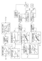
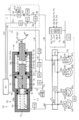
- FIG. 1 is an overall configuration diagram for describing a first embodiment of a vehicle braking control device SC according to the present invention. It is a functional block diagram for explaining the 1st example of processing of pressure regulation control corresponding to a 1st embodiment.
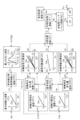
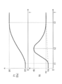
- FIG. 4 is an overall configuration diagram for explaining a second embodiment of the vehicle braking control device SC according to the present invention. It is a functional block diagram for explaining the 2nd processing example (especially the drive processing of electric motor MC) of pressure regulation control corresponding to a 2nd embodiment. It is a functional block diagram for explaining the drive processing of the 1st and 2nd pressure regulating valves UB and UC of the 2nd processing example. It is a time series diagram for demonstrating an effect
- each symbol represents a generic term for each of the four wheels. For example, “WH” represents each wheel, and “CW” represents each wheel cylinder.
- the suffixes “1” and “2” added to the end of the symbol relating to the diagonal type braking system are comprehensive symbols indicating which of the two braking systems it is related to. Specifically, “1” indicates the first system, and “2” indicates the second system. For example, in two master cylinder fluid paths, the first master cylinder valve VM1 and the second master cylinder valve VM2 are described. Further, the suffixes “1” and “2” at the end of the symbol may be omitted. When the suffixes “1” and “2” are omitted, each symbol represents a general term for two braking systems. For example, “VM” represents a master cylinder valve of each braking system.
- the side closer to the reservoir RV (the side farther from the wheel cylinder CW) is called “upper”, and the side closer to the wheel cylinder CW (the side farther from the reservoir RV) is called “lower”.
- the side near the discharge section of the fluid pump HP is called “upstream side”, and the side away from the discharge section is called “downstream side”.
- a first embodiment of the braking control device SC according to the present invention will be described with reference to the overall configuration diagram of FIG.
- a so-called diagonal type also referred to as “X type”
- the fluid path is a path for moving the brake fluid BF that is the working liquid of the brake control device SC, and corresponds to a brake pipe, a fluid unit flow path, a hose, and the like.
- a front-back type fluid path may be adopted as the two-system fluid path.
- the vehicle is a hybrid vehicle equipped with a driving electric motor GN or an electric vehicle.
- the electric motor GN for driving also functions as a generator (generator) for energy regeneration.
- the vehicle includes a braking operation member BP, a wheel cylinder CW, a reservoir RV, a master cylinder CM, a lower fluid unit YL, and a wheel speed sensor VW.
- the braking operation member (for example, a brake pedal) BP is a member operated by the driver to decelerate the vehicle.
- the braking operation member BP By operating the braking operation member BP, the braking torque of the wheel WH is adjusted, and a braking force is generated on the wheel WH.
- a rotating member for example, a brake disk
- a brake caliper is arranged so as to sandwich rotating member KT.
- the brake caliper is provided with a wheel cylinder CW.
- a friction member for example, a brake pad
- a braking torque is generated on the wheel WH by the frictional force generated at this time.
- the reservoir (atmospheric pressure reservoir) RV is a tank for the working liquid, in which the brake fluid BF is stored.
- the master cylinder CM is mechanically connected to the braking operation member BP via a brake rod or the like.
- a tandem type master cylinder is used as the master cylinder CM.
- First and second master cylinder fluid paths HM1 and HM2 are connected to the master cylinder CM.
- Wheel cylinder fluid passages HWi to HWl are connected to wheel cylinders CWi to CWl.
- the master cylinder fluid passage HM is branched into a wheel cylinder fluid passage HW at a portion Bw in the lower fluid unit YL. Therefore, the first master cylinder chamber Rm1 is connected to the wheel cylinders CWi and CWl, and the second master cylinder chamber Rm2 is connected to the wheel cylinders CWj and CWk.
- the lower fluid unit YL is a known fluid unit for executing anti-skid control, vehicle stabilization control, and the like.
- the lower fluid unit YL is configured to include an electric pump and a plurality of solenoid valves. These are controlled by the lower controller ECL.
- Each wheel WH is provided with a wheel speed sensor VW so as to detect the wheel speed Vw.
- the signal of the wheel speed Vw is used for anti-skid control or the like that suppresses the tendency of the wheel WH to lock.
- Each wheel speed Vw detected by the wheel speed sensor VW is input to the lower controller ECL.
- the controller ECL calculates the vehicle body speed Vx based on the wheel speed Vw.
- the braking control device SC includes an operation amount sensor BA, a stroke simulator SS, a simulator valve VS, a master cylinder valve VM, a pressure adjustment unit YA, and an upper controller ECU.
- An operation amount sensor BA is provided so as to detect an operation amount Ba of the braking operation member (brake pedal) BP by the driver.
- a master cylinder pressure sensor PQ that detects the pressure Pm of the master cylinder CM
- an operation displacement sensor SP that detects an operation displacement Sp of the braking operation member BP
- an operation force Fp of the braking operation member BP At least one of the operation force sensors FP to be detected is employed. That is, as the braking operation amount Ba, the operation amount sensor BA determines the hydraulic pressure (master cylinder hydraulic pressure) Pm in the master cylinder CM, the operation displacement Sp of the braking operation member BP, and the operation force Fp of the braking operation member BP. Is detected.
- a stroke simulator (simply referred to as “simulator”) SS is provided to generate an operating force Fp on the braking operation member BP.
- a piston and an elastic body (for example, a compression spring) are provided inside the simulator SS.
- the brake fluid BF is moved from the master cylinder CM to the simulator SS, and the piston is pushed by the flowing brake fluid BF.
- a force is applied to the piston in a direction in which the brake fluid BF is prevented from flowing into the piston.
- An operating force Fp when the braking operation member BP is operated is formed by the elastic body.
- a simulator valve VS is provided between the master cylinder chamber Rm and the simulator SS.
- the simulator valve VS is a two-position solenoid valve (also referred to as an “on / off valve”) having an open position (communication state) and a closed position (cutoff state).
- a normally closed solenoid valve is employed as the simulator valve VS.
- the simulator valve VS is controlled by a drive signal Vs from the controller ECU.
- the braking control device SC When the braking control device SC is started, the simulator valve VS is set to the open position, and the master cylinder CM and the simulator SS are brought into a communication state.
- the operation characteristics of the braking operation member BP (the relationship between the operation displacement Sp and the operation force Fp) are formed by the simulator SS.
- the simulator valve VS can be omitted.
- the first and second master cylinder valves VM1 and VM2 are provided in the first and second master cylinder fluid passages HM1 and HM2 (between the master cylinder CM and the lower fluid unit YL).
- the master cylinder valve VM is a two-position solenoid valve (on / off valve) having an open position (communication state) and a closed position (cutoff state).
- a normally-open solenoid valve is employed as the master cylinder valve VM.
- Master cylinder valve VM is controlled by drive signal Vm from controller ECU.
- the master cylinder valve VM When the brake control device SC is started (when the start switch is turned on), the master cylinder valve VM is set to the closed position, and the master cylinder CM and the wheel cylinder CW are cut off (disconnected state).
- the braking hydraulic pressure Pw is controlled by the pressure adjusting unit YA.
- the pressure regulating unit YA includes an electric pump DC, a check valve GC, a pressure regulating valve UA, a regulated hydraulic pressure sensor PA, and a separation valve VC.
- the electric pump DC is constituted by the electric motor MC and the fluid pump HP.
- the electric motor MC and the fluid pump HP are fixed so that the electric motor MC and the fluid pump HP rotate integrally.
- the electric pump DC (particularly, the electric motor MC) is a power source for increasing the brake hydraulic pressure Pw.
- the electric motor MC is controlled by the upper controller ECU. For example, a three-phase brushless motor is employed as the electric motor MC.
- a reservoir fluid passage HV is connected to a suction port of the fluid pump HP. Further, a pressure regulating fluid passage HC is connected to a discharge port of the fluid pump HP.
- the brake fluid BF is sucked in from the reservoir fluid passage HV through the suction port, and is discharged from the discharge outlet to the pressure regulating fluid passage HC.
- a gear pump is employed as the fluid pump HP.
- a check valve GC (also referred to as a “check valve”) is interposed in the pressure regulating fluid path HC.
- a check valve GC is provided near the discharge part of the fluid pump HP.
- the check valve GC allows the brake fluid BF to move from the reservoir fluid passage HV to the pressure regulating fluid passage HC, but to move from the pressure regulating fluid passage HC to the reservoir fluid passage HV (ie, the braking fluid). Backflow of the liquid BF) is prevented.
- the pressure regulating valve UA is connected to the pressure regulating fluid passage HC and the reservoir fluid passage HV.
- the pressure regulating valve UA is a linear solenoid valve (also referred to as a “proportional valve” or a “differential pressure valve”) in which an opening amount (lift amount) is continuously controlled based on an energized state (for example, supply current). It is.
- a normally-open solenoid valve is employed as the pressure regulating valve UA.
- the pressure regulating valve UA is controlled by the upper controller ECU based on the drive signal Ua.
- the brake fluid BF recirculates in the order of “HV ⁇ HP ⁇ GC ⁇ UA ⁇ HV” as shown by the broken line arrow (A). That is, in the pressure adjusting unit YA, a return path of the brake fluid BF (a fluid path in which the flow of the brake fluid BF returns to the original flow) including the fluid pump HP, the check valve GC, and the pressure regulator valve UA is formed. I have.
- the pressure regulating valve UA can be connected to the reservoir RV via a second reservoir fluid passage HX different from the first reservoir fluid passage HV.
- the return path (A) of the brake fluid BF includes the reservoir RV, and is in the order of “HV ⁇ HP ⁇ GC ⁇ UA ⁇ HX ⁇ RV ⁇ HV”.
- the hydraulic pressure (adjusted hydraulic pressure) Pa in the pressure adjusting fluid passage HC is low and substantially “0 (atmospheric pressure)”.
- the regulated hydraulic pressure Pa is increased. That is, the adjustment hydraulic pressure Pa is adjusted by the orifice effect of the pressure adjustment valve UA.
- An adjustment hydraulic pressure sensor PA is provided in the pressure adjustment fluid passage HC (particularly, between the check valve GC and the pressure adjustment valve UA) so as to detect the adjustment hydraulic pressure Pa.
- the detected adjusted hydraulic pressure Pa is input to the controller ECU.
- the pressure regulating fluid passage HC is connected to the first and second master cylinder fluid passages HM1 and HM2 via the first and second introduction fluid passages HD1 and HD2.
- an introduction fluid passage is provided between a portion Bc of the pressure regulation fluid passage HC between the pressure regulating valve UA and the check valve GC and a portion Bw of the master cylinder fluid passage HM below the master cylinder valve VM.
- HD is connected.
- a separation valve VC is provided in the introduction fluid path HD.
- the separation valve VC is a two-position solenoid valve (on / off valve) having an open position and a closed position.
- a normally closed solenoid valve is employed as the separation valve VC.
- the separation valve VC is controlled by a drive signal Vc from the controller ECU.
- the separation valve VC is set to the open position. Therefore, when the brake control device SC operates, the master cylinder valve VM is in the closed position, and thus the adjustment hydraulic pressure Pa is introduced (supplied) from the pressure adjustment unit YA to the wheel cylinder CW. That is, the same adjusted hydraulic pressure Pa is supplied to the wheel cylinders CWi to CWl.
- This control is referred to as “same pressure regulation”.
- the upper controller also referred to as “upper electronic control unit” ECU includes an electric circuit board on which the microprocessor MP and the drive circuit DR are mounted, and a control algorithm programmed in the microprocessor MP.
- the electric motor MC and various solenoid valves VM, VS, VC, and UA are controlled by the controller ECU based on the braking operation amount Ba, the vehicle body speed Vx, and the adjusted hydraulic pressure Pa.
- drive signals Vm, Vs, Vc, and Ua for controlling various solenoid valves VM, VS, VC, and UA are calculated based on a control algorithm in the microprocessor MP.
- a drive signal Mc for controlling the electric motor MC is calculated. Then, based on these drive signals Vm, Vs, Vc, Ua, Mc, the solenoid valves VM, VS, VC, UA, and the electric motor MC are driven.
- the controller ECU is connected to another controller (electronic control unit) via a vehicle-mounted communication bus BS.
- the regenerative amount Rg is transmitted from the controller ECU to the driving controller ECD so as to execute cooperative control of friction braking and regenerative braking (so-called regenerative cooperative control).
- the “regenerative amount Rg” is a state quantity (including Fg and Fx) representing the magnitude of the regenerative braking force generated by the driving motor GN.
- the vehicle speed Vx calculated by the lower controller ECL is transmitted to the upper controller ECU via the communication bus BS.
- the controller ECU is provided with a drive circuit DR for driving the solenoid valves VM, VS, VC, UA, and the electric motor MC.
- a bridge circuit is formed by switching elements (power semiconductor devices such as MOS-FETs and IGBTs) so as to drive the electric motor MC.
- the energization state of each switching element is controlled based on the motor drive signal Mc, and the output of the electric motor MC is controlled.
- their excitation states are controlled based on the drive signals Vm, Vs, Vc, Ua so as to drive the solenoid valves VM, VS, VC, UA.
- the pressure regulation control is drive control of the electric motor MC and the pressure regulation valve UA for controlling the regulated hydraulic pressure Pa.
- the control algorithm is programmed in the upper controller ECU.
- the pressure regulation control processing includes a required braking force calculation block FD, a maximum regenerative force calculation block FX, a target friction braking force calculation block FM, a target hydraulic pressure calculation block PT, a reference flow rate calculation block QO, a hydraulic pressure change amount calculation block DP, and an adjustment.
- the required braking force Fd is calculated based on the operation amount Ba and the calculation map Zfd.
- the required braking force Fd is a target value of the total braking force F acting on the vehicle, and is a braking force obtained by adding “the friction braking force Fm by the braking control device SC” and “the regenerative braking force Fg by the generator GN”.
- the required braking force Fd is determined to be “0” according to the calculation map Zfd when the operation amount Ba is in the range from “0” to the predetermined value bo, and when the operation amount Ba is equal to or more than the predetermined value bo, the operation amount Ba increases. Accordingly, the calculation is performed so as to monotonously increase from “0”.
- the maximum value of the regenerative braking force (referred to as “maximum regenerative power”) Fx is calculated based on the vehicle speed Vx and the calculation map Zfx.
- the regeneration amount of the generator GN is limited by the rating of the power transistor (IGBT or the like) of the drive controller ECD and the charge acceptability of the battery.
- the regeneration amount of the generator GN is controlled to a predetermined power (electric energy per unit time). Since the electric power (power) is constant, the regenerative torque around the wheel shaft by the generator GN is inversely proportional to the rotation speed of the wheel WH (that is, the vehicle speed Vx). Also, when the rotation speed Ng of the generator GN decreases, the regeneration amount decreases. Furthermore, an upper limit is provided for the amount of regeneration.
- the maximum regenerative power Fx in a range where the vehicle speed Vx is equal to or more than “0” and lower than the first predetermined speed vo, the maximum regenerative power Fx is set to increase as the vehicle speed Vx increases. .
- the maximum regenerative force Fx is determined to be the upper limit value fx.
- the maximum regenerative force Fx is set to decrease as the vehicle speed Vx increases.
- the relationship between the vehicle speed Vx and the maximum regenerative power Fx is represented by a hyperbola (that is, the regenerative power is constant).
- the predetermined values vo and vp are constants set in advance.
- the rotation speed Ng of the generator GN may be employed instead of the vehicle body speed Vx.
- the target friction braking force Fm is calculated based on the required braking force Fd and the maximum regenerative force Fx.
- the target friction braking force Fm is a target value of the braking force to be achieved by friction braking.
- a regeneration amount Rg is calculated based on the regenerative braking force Fg.
- the regeneration amount Rg is a target value of the regeneration amount of the generator GN.
- the regeneration amount Rg is transmitted from the upper controller ECU to the drive controller ECD via the communication bus BS.
- the target hydraulic pressure Pt is calculated based on the target frictional braking force Fm and the calculation map Zpt.
- the target hydraulic pressure Pt is a target value of the adjusted hydraulic pressure Pa adjusted by the pressure adjusting unit YA.
- the target hydraulic pressure Pt is determined according to the calculation map Zpt such that the target hydraulic pressure Fm monotonically increases from “0” as the target friction braking force Fm increases from “0”. That is, the target friction pressure Ft is determined by converting the target friction braking force Fm into a hydraulic pressure.
- the reference flow rate Qo is calculated based on the target hydraulic pressure Pt and the calculation map Zqo.
- the reference flow rate Qo is a target value of the discharge amount (flow rate) of the electric pump DC (that is, the fluid pump HP), which is the minimum necessary for adjusting the fluid pressure by the orifice effect of the pressure regulating valve UA.
- the reference flow rate Qo is determined according to the calculation map Zqo so as to monotonously increase from the predetermined flow rate qo as the target hydraulic pressure Pt increases from “0”. This is based on the fact that the higher the hydraulic pressure, the greater the internal leakage of the fluid pump HP.
- the predetermined flow rate qo is a preset constant.
- the hydraulic pressure change amount dP is calculated based on the target hydraulic pressure Pt.
- the hydraulic pressure change amount dP is a state amount (referred to as “operation speed equivalent amount”) corresponding to the operation speed dB of the braking operation member BP.
- the target hydraulic pressure Pt is differentiated with respect to time to determine the hydraulic pressure change amount dP.
- the hydraulic pressure change amount dP is calculated so as to increase as the operation speed dB of the brake operation member BP (the time change amount of the operation amount Ba) increases.
- the adjustment flow rate Qh is calculated based on the hydraulic pressure change amount dP, the target hydraulic pressure Pt, and the calculation map Zqh.
- the adjustment flow rate Qh is a target value of the discharge flow rate of the electric pump DC required to increase the adjustment hydraulic pressure Pa.
- the adjusted flow rate Qh is calculated to be “0” when the fluid pressure change amount dP is equal to or less than “0” according to the calculation map Zqh, and monotonically increases from “0” as the fluid pressure change amount dP increases from “0”. To be determined.
- the adjustment flow rate Qh is determined so as to increase as the target hydraulic pressure Pt decreases, and to decrease as the target hydraulic pressure Pt increases.
- the adjusted hydraulic pressure Pa (resulting in the brake hydraulic pressure Pw) is based on an increase according to the rigidity (non-linear spring constant) of the brake caliper, friction material and the like. That is, when the adjustment hydraulic pressure Pa is low, a large amount of flow is required, but when the adjustment hydraulic pressure Pa is high, the flow rate is not so required. Therefore, the adjustment flow rate Qh is determined to be larger as the target hydraulic pressure Pt is smaller.
- the target flow rate Qt is calculated based on the reference flow rate Qo and the adjusted flow rate Qh.
- the target rotation speed calculation block NT the target rotation speed Nt is calculated based on the target flow rate Qt.
- the target rotation speed Nt is a target value of the rotation speed of the electric pump DC (particularly, the electric motor MC).
- the target flow rate Qt is converted and calculated into the target rotation speed Nt.
- the actual rotation speed calculation block NA the actual rotation speed Na is calculated based on the actual rotation angle Ka (the value detected by the rotation angle sensor KA). Specifically, the actual rotation angle Ka is differentiated with respect to time to determine the actual rotation speed Na.
- the rotation speed feedback control of the electric motor MC is executed based on the target rotation speed Nt and the actual rotation speed Na. That is, the drive signal Mc is determined such that the actual rotation speed Na approaches and matches the target rotation speed Nt.
- the switching element of the drive circuit DR is driven based on the drive signal Mc, and the electric motor MC is controlled.
- the hydraulic pressure change amount dP (operation speed equivalent amount) corresponds to the operation of the brake operation member BP.
- the hydraulic pressure change amount dP becomes larger than “0” (that is, “dP> 0”).
- the hydraulic pressure change amount dP becomes smaller than “0” (that is, “dP ⁇ 0”).
- the adjustment flow rate Qh is determined to increase as the hydraulic pressure change amount dP increases (the increasing gradient of the adjustment hydraulic pressure Pa increases).
- the target rotation speed Nt increases as the hydraulic pressure change amount dP increases.
- the reference flow rate Qo is sufficient for the flow rate of the brake fluid BF (discharge flow rate of the electric pump DC). The same applies to the case where the adjustment hydraulic pressure Pa is reduced. Therefore, when the fluid pressure change amount dP is equal to or less than “0”, the adjustment flow rate Qh is calculated to be “0”. Therefore, when the operation of the brake operation member BP is increased or decreased after the operation is increased, the increased target rotation speed Nt is decreased.
- the hydraulic pressure change amount dP corresponding to the operation of the braking operation member BP is calculated, the rotation speed (rotation speed) of the electric pump DC (particularly, the electric motor MC) is determined, and the electric pump DC (particularly, the fluid pump HP) is set. Since the unnecessary flow rate is not discharged, the power consumption of the braking control device SC can be reduced. Further, when a sudden increase in the brake fluid pressure Pw is required (for example, when the brake operating member BP is suddenly operated), the rotation speed Na of the electric motor MC is rapidly increased, and a sufficient fluid amount (braking) is supplied to the wheel cylinder CW. Liquid BF). Therefore, the boost response of the brake fluid pressure Pw is improved, the time delay in the feedback control based on the deviation hP is reduced, and the pressure regulation accuracy of the brake fluid pressure Pw is ensured.
- the adjustment flow rate Qh was calculated based on the hydraulic pressure change amount dP.
- the target hydraulic pressure Pt is calculated according to the operation amount Ba or the target friction braking force Fm
- the time differential value (operation speed) dB of the operation amount Ba or the time differential value of the target friction braking force Fm is calculated.
- the adjustment flow rate Qh can be calculated based on the value (braking force change amount) dF. That is, at least one of the hydraulic pressure change amount dP, the operation speed dB, and the friction braking force change amount dF corresponds to the “operation speed equivalent amount”.
- the operation speed equivalent amount is a state amount representing an increase or decrease of the operation amount Ba of the braking operation member BP. That is, “when the operation speed equivalent amount is larger than zero” indicates an increase in the operation, “when the operation speed equivalent amount is zero” holds the operation, and “when the operation speed equivalent amount is smaller than zero”. The decrease in operations is represented respectively.
- the required energization amount Is is calculated based on the target hydraulic pressure Pt, the target flow rate Qt, and the calculation map Zis.
- the required energization amount Is is a target value of the energization amount (current) supplied to the pressure regulating valve UA.
- the required energization amount Is is determined in accordance with the calculation map Zis so as to increase monotonically from "0" to "upwardly convex" as the target hydraulic pressure Pt increases from "0". Further, the required energization amount Is is determined to be larger as the target flow rate Qt is smaller, and to be smaller as the target flow rate Qt is larger, in accordance with the calculation map Zis. Since the pressure regulating valve UA is a normally open type, the required flow amount Is is calculated to be smaller as the target flow rate Qt is larger, and the opening amount of the pressure regulating valve UA is increased.
- the compensation energization amount Ih is calculated based on the deviation hP between the target hydraulic pressure Pt and the adjustment hydraulic pressure Pa, and the arithmetic map Zih.
- the compensation energization amount Ih is a target value of the energization amount (current) supplied to the pressure regulating valve UA so that the adjustment hydraulic pressure Pa matches the target hydraulic pressure Pt.
- the adjusted hydraulic pressure Pa the value detected by the adjusted hydraulic pressure sensor PA
- the compensation energization amount Ih is determined to increase as the hydraulic pressure deviation hP increases.
- the hydraulic pressure deviation hP is within the range from the predetermined value “ ⁇ po” to the predetermined value po, the compensation energization amount Ih is determined to be “0”.
- the predetermined value po is a preset positive constant.
- the target energization amount It is calculated based on the required energization amount Is and the compensation energization amount Ih.
- energization amount feedback control of the pressure regulating valve UA is executed based on the target energization amount It and the actual energization amount Ia. That is, the drive signal Ua is determined so that the actual energization amount Ia approaches and matches the target energization amount It.
- the actual energization amount Ia is detected by an energization amount sensor IA provided in the drive circuit DR. Then, the drive circuit DR is driven based on the drive signal Ua, and the pressure regulating valve UA is controlled. As a result, the adjustment hydraulic pressure Pa is controlled so as to approach and match the target hydraulic pressure Pt.
- the electric motor MC is stopped at the time of holding or returning the brake operation member BP, further power saving is achieved.
- ⁇ Second embodiment of braking control device SC> A second embodiment of the braking control device SC according to the present invention will be described with reference to the overall configuration diagram of FIG.
- a so-called front-rear type is used as the two-system fluid path.
- the same pressure adjustment is performed in which the adjustment hydraulic pressure Pa is supplied to the four wheel cylinders CW.
- the front wheel cylinder CWf and the rear wheel cylinder CWr are separately provided. Controlled. This control is referred to as “independent pressure regulation”.
- each symbol represents a generic term for each of the four wheels.
- the suffixes “f” and “r” added to the end of the symbols related to the front and rear brake systems are comprehensive symbols indicating which system of the front and rear wheels, and “f” is the front wheel system. , “R” indicate a rear wheel system.
- the suffixes “1” and “2” added to the end of the symbol related to the diagonal type braking system are comprehensive symbols indicating which system it is, and “1” is the first system. , “2” indicate the second system.
- the suffixes “f”, “r”, “1”, “2” at the end of the symbol can be omitted. In this case, each symbol represents a general term for each of the two braking systems.
- the side farther from the wheel cylinder CW is called “upper”, and the side closer to the wheel cylinder CW is called “lower”.
- the side closer to the discharge part of the fluid pump HP is “upstream side”, and the side farther away is “downstream side”.
- the braking control device SC includes an upper fluid unit YU.
- the upper fluid unit YU is controlled by the upper controller ECU.
- the vehicle is provided with a lower fluid unit YL controlled by a lower controller ECL.
- the upper controller ECU and the lower controller ECL are connected via a communication bus BS so that signals (sensor detection values, calculation values, etc.) are shared.
- the generator GN is provided on the front wheel WHf.
- the upper fluid unit YU in the second embodiment includes an operation amount sensor BA, a master unit YM, a pressure adjustment unit YC, and a regenerative cooperation unit YK.
- An operation amount sensor BA is provided so as to detect an operation amount Ba of the braking operation member (brake pedal) BP by the driver.
- An operation displacement sensor SP that detects an operation displacement Sp of the brake operation member BP is provided as the operation amount sensor BA.
- An operating force sensor FP is provided to detect the operating force Fp of the braking operation member BP.
- a simulator hydraulic pressure sensor PS is provided as the operation amount sensor BA so as to detect a hydraulic pressure (simulator hydraulic pressure) Ps in the stroke simulator SS.
- An input hydraulic pressure sensor PN is provided to detect a hydraulic pressure (input hydraulic pressure) Pn in the input chamber Rn of the regenerative cooperation unit YK.
- the operation amount sensor BA is a generic name of the above-described operation displacement sensor SP and the like.
- the braking operation amount Ba at least one of the operation displacement Sp, the operation force Fp, the simulator hydraulic pressure Ps, and the input hydraulic pressure Pn is adopted. Is done.
- the detected braking operation amount Ba is input to the upper controller ECU.
- the master cylinder hydraulic pressure Pm does not correspond to the operation amount Ba.
- the master unit YM adjusts the hydraulic pressure (front wheel brake hydraulic pressure) Pwf in the front wheel cylinder CWf via the master cylinder chamber Rm.
- the master unit YM includes a master cylinder CM, a master piston PM, and a master elastic body SM.
- the master cylinder CM is a stepped cylinder member having a bottom (that is, having a small diameter portion and a large diameter portion).
- a single type is used as the master cylinder CM.
- Master piston PM is a piston member inserted inside master cylinder CM, and has a flange portion (flange) Tm. Master cylinder CM and master piston PM are sealed with a seal SL.
- the master piston PM is movable in conjunction with the operation of the braking operation member BP.
- the inside of the master cylinder CM is partitioned into three hydraulic chambers Rm, Rs, and Ro by the master piston PM.
- the master piston PM can move smoothly along the central axis Jm of the master cylinder CM.
- the master cylinder chamber (also simply referred to as “master chamber”) Rm is a hydraulic chamber partitioned by the “small-diameter inner peripheral portion and small-diameter bottom portion of the master cylinder CM” and the end of the master piston PM.
- a servo hydraulic chamber (simply referred to as a “servo chamber”) Rs and a reaction force hydraulic chamber (simply referred to as a “reaction force chamber”) Ro are formed by a flange portion Tm of the master piston PM. It is divided into.
- the servo chamber Rs is a hydraulic chamber partitioned by “the large-diameter inner peripheral portion and the large-diameter bottom portion of the master cylinder CM” and the collar portion Tm of the master piston PM.
- the master chamber Rm and the servo chamber Rs are arranged to face each other with the collar Tm interposed therebetween.
- the front chamber pressure adjusting fluid passage HF is connected to the servo chamber Rs, and the adjusting hydraulic pressure Pc is introduced from the pressure adjusting unit YC.
- the reaction chamber Ro is a hydraulic chamber partitioned by a large-diameter inner peripheral portion of the master cylinder CM, a stepped portion, and a flange portion Tm of the master piston PM.
- the reaction chamber Ro is sandwiched between the master hydraulic chamber Rm and the servo hydraulic chamber Rs in the direction of the central axis Jm, and is located therebetween. Therefore, when the volume of the servo chamber Rs is increased, the volume of the reaction chamber Ro is reduced. Conversely, when the servo chamber volume is reduced, the reaction chamber volume is increased.
- a simulator fluid passage HS is connected to the reaction force chamber Ro. The amount of the brake fluid BF in the upper fluid unit YU is adjusted by the reaction force chamber Ro.
- a master elastic body (for example, a compression spring) SM is provided between the end of the master piston PM and the small diameter bottom of the master cylinder CM.
- the master elastic body SM presses the master piston PM against the large-diameter bottom portion of the master cylinder CM in the direction of the center axis Jm of the master cylinder CM.
- the master piston PM is in contact with the large-diameter bottom of the master cylinder CM.
- the position of the master piston PM in this state is referred to as “the initial position of the master unit YM”.
- a through hole is provided in the master cylinder CM, and is connected to the reservoir RV via the supply fluid passage HU.
- the master piston PM When the master piston PM is at the initial position, the master chamber Rm is communicated with the reservoir RV via the through hole and the supply fluid path HU.
- the master chamber Rm generates an urging force Fb (referred to as “retracting force”) in the retreating direction Hb along the central axis Jm by its internal pressure (“master cylinder pressure”, also referred to as “master pressure”) Pm. Assigned to master piston PM.
- the servo chamber Rs applies an urging force Fa (referred to as “forward force”) in the forward direction Ha, which opposes the backward force Fb, to the master piston PM by its internal pressure (that is, the introduced adjusted hydraulic pressure Pc).
- a master cylinder pressure sensor PQ is provided to detect master pressure Pm.
- the master cylinder fluid pressure sensor PQ can be provided in the master cylinder fluid passage HM.
- master cylinder hydraulic pressure sensor PQ may be included in lower fluid unit YL.
- the pressure adjustment unit YC includes an electric pump DC, a check valve GC, first and second pressure adjustment valves UB, UC, and first and second adjustment hydraulic pressure sensors PB, PC.
- the fluid pressure (front wheel brake fluid pressure) Pwf of the front wheel cylinder CWf and the fluid pressure (rear wheel brake fluid pressure) Pwr of the rear wheel cylinder CWr are independently and individually adjusted by the pressure regulating unit YC ( That is, the above independent pressure regulation).
- brake fluid pressure Pwf of front wheel WHf provided with generator GN is independently adjusted within a range equal to or less than brake fluid pressure Pwr of rear wheel WHr not provided with generator GN.
- the electric pump DC is composed of an electric motor MC and a fluid pump HP, which rotate integrally.
- the suction port is connected to the first reservoir fluid path HV
- the discharge port is connected to one end of the pressure regulating fluid path HC.
- a check valve GC is provided in the pressure regulating fluid path HC.
- the other end of the pressure regulating fluid path HC is connected to the second reservoir fluid path HX via the second pressure regulating valve UC.
- the first and second reservoir fluid paths HV, HX are connected to a reservoir RV.
- Two pressure regulating valves UB and UC are provided in series in the pressure regulating fluid path HC.
- the pressure regulating fluid passage HC is provided with a first pressure regulating valve UB
- the other end of the pressure regulating fluid passage HC is provided with a second pressure regulating valve UC.
- the end of the second reservoir fluid passage HX is connected to the second pressure regulating valve UC. That is, in the recirculation path (A), the first pressure regulating valve UB is arranged on the upstream side, and the second pressure regulating valve UC is arranged on the downstream side.
- the first and second pressure regulating valves UB and UC are linear type solenoid valves (valve opening amounts are continuously controlled based on the energized state (for example, supply current)). Proportional valve, differential pressure valve).
- the first and second pressure regulating valves UB, UC are controlled by the controller ECU based on the drive signals Ub, Uc.
- normally-open solenoid valves are employed as the first and second pressure regulating valves UB and UC.
- a return (A) of the brake fluid BF is formed, such as “HV ⁇ HP ⁇ GC ⁇ UB ⁇ UC ⁇ HX ⁇ RV ⁇ HV”. That is, the return path (A) of the brake fluid BF includes the fluid pump HP, the first and second pressure regulating valves UB and UC, and the reservoir RV. In addition, as shown in the first embodiment, the second pressure regulating valve UC may be connected to the first reservoir fluid passage HV. In this case, the return path (A) is in the order of “HV ⁇ HP ⁇ GC ⁇ UB ⁇ UC ⁇ HV”.
- the fluid pressures (regulated fluid pressures) Pb and Pc in the pressure regulating fluid passage HC are: Both are approximately “0 (atmospheric pressure)”.
- the fluid pressure upstream of the first pressure regulating valve UB for example, The fluid pressure (first regulated fluid pressure) Pb) between the fluid pump HP and the first pressure regulating valve UB is increased from “0”.
- the hydraulic pressure upstream of the second pressure regulating valve UC in the pressure regulating fluid passage HC is increased from “0”.
- the second regulated hydraulic pressure Pc regulated by the second regulated pressure valve UC is equal to the first regulated hydraulic pressure Pb. It is as follows.
- the first pressure adjustment valve UB adjusts the first adjustment fluid pressure Pb
- the second pressure adjustment valve UC reduces the first adjustment fluid pressure Pb to adjust the second adjustment fluid pressure Pc.
- the second pressure adjustment valve UC adjusts the second adjustment hydraulic pressure Pc so as to increase from “0 (atmospheric pressure)”
- the first pressure adjustment valve UB adjusts the first adjustment hydraulic pressure Pb to the second adjustment hydraulic pressure Pb. It is adjusted to increase from the adjusted hydraulic pressure Pc.
- first and second adjustment hydraulic pressure sensors PB and PC are provided to detect the first and second adjustment hydraulic pressures Pb and Pc. Since the specifications of the master unit YM (pressure receiving area of the master piston PM, etc.) are known, a mass cylinder hydraulic pressure sensor PQ may be used instead of the second adjustment hydraulic pressure sensor PC. That is, the second adjustment hydraulic pressure sensor PC can be omitted.
- the pressure regulating fluid passage HC is branched to a rear wheel pressure regulating fluid passage HR at a portion Bh between the fluid pump HP and the first pressure regulating valve UB.
- the rear wheel pressure adjusting fluid passage HR is connected to the rear wheel cylinder CWr via the lower fluid unit YL. Therefore, the first adjusted hydraulic pressure Pb is directly introduced (supplied) to the rear wheel hole cylinder CWr.
- the pressure regulating fluid path HC is branched into a front wheel pressure regulating fluid path HF at a portion Bg between the first pressure regulating valve UB and the second pressure regulating valve UC.
- the front wheel pressure adjusting fluid passage HF is connected to the servo chamber Rs.
- the second adjusted hydraulic pressure Pc is introduced (supplied) to the servo chamber Rs. Since the master cylinder CM is connected to the front wheel cylinder CWf via the lower fluid unit YL, the second adjusted hydraulic pressure Pc is indirectly introduced to the front wheel cylinder CWf via the master cylinder CM. You.
- the first adjustment hydraulic pressure Pb (the hydraulic pressure between the fluid pump HP and the first pressure regulating valve UB) and the second adjustment hydraulic pressure Pc (the The hydraulic pressure between the first pressure regulating valve UB and the second pressure regulating valve UC) is adjusted independently and separately.
- the regenerative cooperative control is executed in consideration of the front-rear distribution of the braking force, so that the deceleration and stability of the vehicle can be ensured, and the regenerative energy can be maximized.
- the regenerative cooperation unit YK By the regenerative cooperative unit YK, cooperative control of friction braking and regenerative braking (referred to as “regenerative cooperative control”) is achieved. For example, a state where the braking operation member BP is operated by the regenerative cooperation unit YK but the braking hydraulic pressure Pw is not generated may be formed.
- the regenerative cooperation unit YK includes an input cylinder CN, an input piston PK, an input elastic body SN, a first on-off valve VA, a second on-off valve VB, a stroke simulator SS, a simulator hydraulic pressure sensor PS, and an input hydraulic pressure sensor PN. Be composed.
- the input cylinder CN is a cylinder member having a bottom fixed to the master cylinder CM.
- the input piston PK is a piston member inserted inside the input cylinder CN.
- the input piston PK is mechanically connected to the braking operation member BP via a clevis (U-shaped link) so as to interlock with the braking operation member BP.
- the input piston PK is provided with a flange (flange) Tn.
- An input elastic body (for example, a compression spring) SN is provided between the mounting surface of the input cylinder CN to the master cylinder CM and the collar portion Tn of the input piston PK.
- the input elastic body SN presses the collar portion Tn of the input piston PK against the bottom of the input cylinder CN in the direction of the central axis Jm.
- a gap Ks between the end face Mq of the master piston PM and the end face Mg of the input piston PK is set to a predetermined distance ks (referred to as an “initial gap”) inside the input cylinder CN.
- the master piston PM and the input piston It is separated from PK by a predetermined distance ks.
- the predetermined distance ks corresponds to the maximum value of the regeneration amount Rg.
- the input chamber Rn of the regenerative cooperation unit YK and the reaction force chamber Ro of the master unit YM are connected by the simulator fluid path HS.
- a first on-off valve VA is provided in the simulator fluid path HS.
- the first on-off valve VA is a normally closed solenoid valve having an open position and a closed position.
- a third reservoir fluid passage HT is connected to a portion Bs of the simulator fluid passage HS between the first opening / closing valve VA and the reaction force chamber Ro.
- a second on-off valve VB is provided in the third reservoir fluid passage HT.
- the second on-off valve VB is a normally-open solenoid valve having an open position and a closed position.
- the first and second on-off valves VA and VB are two-position solenoid valves (on / off valves) having an open position (communication state) and a closed position (cutoff state).
- the first and second on-off valves VA and VB are controlled by the upper controller ECU based on the drive signals Va and Vb.
- the brake control device SC When the brake control device SC is activated, energization of the first and second on-off valves VA and VB is started. Then, the first on-off valve VA is in the open position, and the second on-off valve VB is in the closed position.
- the simulator SS is connected to the simulator fluid path HS at a portion Bo between the first on-off valve VA and the reaction force chamber Ro.
- the input chamber Rn of the regenerative cooperation unit YK is connected to the simulator SS by the simulator fluid path HS.
- the first on-off valve VA is set to the open position
- the second on-off valve VB is set to the closed position.
- the flow path to the reservoir RV is shut off in the third reservoir fluid passage HT, so that the brake fluid BF is moved from the input chamber Rn of the input cylinder CN into the simulator SS.
- an operation force Fp when the brake operation member BP is operated is generated.
- the third reservoir fluid passage HT is connected to the reservoir RV. Part of the third reservoir fluid passage HT can be shared with the first and second reservoir fluid passages HV, HX. However, it is desirable that the first and second reservoir fluid passages HV, HX and the third reservoir fluid passage HT are separately connected to the reservoir RV.
- the fluid pump HP sucks the brake fluid BF from the reservoir RV via the first reservoir fluid passage HV. At this time, bubbles may be mixed in the first reservoir fluid passage HV. For this reason, the third reservoir fluid path HT is directly connected to the reservoir RV so as to prevent air bubbles from entering the input cylinder CN and the like.
- a simulator fluid pressure sensor PS is provided in the simulator fluid path HS between the first on-off valve VA and the reaction force chamber Ro so as to detect a fluid pressure (referred to as “simulator fluid pressure”) Ps in the simulator SS.
- An input hydraulic pressure sensor PN is provided in the simulator fluid path HS between the first on-off valve VA and the input chamber Rn so as to detect a hydraulic pressure (referred to as “input hydraulic pressure”) Pn in the input chamber Rn.
- the simulator hydraulic pressure sensor PS and the input hydraulic pressure sensor PN are one of the above-described braking operation amount sensors BA.
- the detected hydraulic pressures Ps and Pn are input to the upper controller ECU as the braking operation amount Ba.
- the upper motor controller MC controls the electric motor MC and the solenoid valves VA, VB, UB, and UC by the upper controller ECU to control the braking operation amount Ba (Sp, Fp, Ps, Pn), the vehicle speed Vx, and the adjusted hydraulic pressure (detected value) Pb. , Pc.
- the upper controller ECU calculates drive signals Va, Vb, Ub, and Uc for controlling various solenoid valves VA, VB, UB, and UC.
- a drive signal Mc for controlling the electric motor MC is calculated. Then, based on the drive signals Va, Vb, Ub, Uc, Mc, the solenoid valves VA, VB, UB, UC and the electric motor MC are driven.
- the master cylinder hydraulic pressure Pm may be employed instead of the second adjustment hydraulic pressure Pc.
- the required braking force calculation block FD and the maximum regenerative force calculation block FX are the same as in the first processing example.
- the required braking force Fd (the target value of the total braking force F) is calculated based on the operation amount Ba and the calculation map Zfd.
- the required braking force Fd is determined to be “0” when the operation amount Ba is in the range from “0” to the predetermined value bo.
- the required braking force Fd becomes “0” as the operation amount Ba increases. Is calculated to increase monotonically from.
- the maximum regenerative power (maximum regenerative braking force that can be generated) Fx is calculated based on the vehicle speed Vx (or the generator rotational speed Ng) and the calculation map Zfx.
- Vx or the generator rotational speed Ng
- Zfx the maximum regenerative force
- the front and rear wheel target frictional braking force calculation block FFR calculates front wheel and rear wheel target frictional braking forces Fmf and Fmr based on the required braking force Fd and the maximum regenerative force Fx.
- the front and rear wheel target friction braking forces Fmf and Fmr are target values of the front and rear wheel target friction braking forces Fmf and Fmr.
- a distribution ratio of the braking force (particularly, a ratio of the rear wheel braking force to the entire braking force F, which is referred to as a “rear wheel ratio Hr”) is set.
- the rear wheel ratio Hr can be determined as a preset constant (predetermined value) hr.
- the rear wheel ratio Hr can be determined based on at least one of the turning amount Ta, the vehicle speed Vx, and the required braking force Fd.
- the turning state amount Ta is a variable representing the turning state of the vehicle, and corresponds to, for example, a yaw rate and a lateral acceleration.
- the required braking force Fd is equal to or less than the maximum regenerative force Fx based on the required braking force Fd and the maximum regenerative force Fx. Is done. That is, it is determined whether or not the braking force Fd requested by the driver can be achieved only by the regenerative braking force.
- the target regenerative braking force Fg is determined to be equal to the required braking force Fd, and the target friction braking forces Fmf and Fmr of the front and rear wheels are calculated to “0” (that is, “0”).
- the target regenerative braking force Fg, the supplemental braking force Fh, and the rear wheel reference force Fs are calculated.
- the rear wheel reference force Fs is calculated based on the required braking force Fd and the rear wheel ratio Hr.
- the regeneration amount Rg is a target value of the regeneration amount of the generator GN.
- the regeneration amount Rg is transmitted from the upper controller ECU to the drive controller ECD via the communication bus BS.
- the front wheel target hydraulic pressure Ptf is calculated based on the front wheel target friction braking force Fmf and the calculation map Zpf.
- the front wheel target hydraulic pressure Ptf is a target value of the second adjustment hydraulic pressure Pc adjusted by the pressure adjustment unit YC.
- the front wheel target hydraulic pressure Ptf is determined in accordance with the calculation map Zpf so that the front wheel target frictional braking force Fmf monotonically increases from “0” as the front wheel target frictional braking force Fmf increases from “0”.
- the rear wheel target hydraulic pressure Ptr is calculated based on the rear wheel target frictional braking force Fmr and the calculation map Zpr.
- the rear wheel target hydraulic pressure Ptr is a target value of the first adjusted hydraulic pressure Pb adjusted by the pressure adjusting unit YC.
- the rear wheel target hydraulic pressure Ptr is determined according to the calculation map Zpr such that the rear wheel target frictional braking force Fmr monotonically increases from “0" as the rear wheel target friction braking force Fmr increases from "0".
- a front wheel hydraulic pressure change amount dPf (corresponding to “operation speed equivalent amount”) is calculated based on the front wheel target hydraulic pressure Ptf.
- the front wheel target hydraulic pressure Ptf is differentiated with respect to time to determine the front wheel hydraulic pressure change amount dPf.
- the front wheel hydraulic pressure change amount dPf is calculated so as to increase as the operation speed dB of the brake operation member BP (the time change amount of the operation amount Ba) increases.
- a rear wheel hydraulic pressure change amount dPr (corresponding to “operation speed equivalent amount”) is calculated based on the rear wheel target hydraulic pressure Ptr.
- the rear wheel target hydraulic pressure Ptr is differentiated with respect to time, and the rear wheel hydraulic pressure change amount dPr is determined.
- the rear wheel hydraulic pressure change amount dPr is calculated so as to increase as the operation speed dB of the brake operation member BP (the time change amount of the operation amount Ba) increases.
- the reference flow rate calculation block QO the reference flow rate Qo is calculated based on the reference hydraulic pressure Px and the calculation map Zqo.
- the reference flow rate Qo is a target value of the discharge amount (flow rate) of the electric pump DC, which is the minimum necessary for adjusting the fluid pressure by the orifice effect of the first and second pressure regulating valves UB and UC.
- the reference flow rate Qo is calculated by monotonically increasing from the predetermined flow rate qo as the reference hydraulic pressure Px increases from "0" according to the calculation map Zqo.
- the predetermined flow rate qo is a preset constant.
- the front wheel adjustment flow rate Qf is calculated based on the front wheel hydraulic pressure change amount dPf, the front wheel target hydraulic pressure Ptf, and the calculation map Zqf.
- the front wheel adjustment flow rate Qf is calculated to be “0” according to the calculation map Zqf when the front wheel hydraulic pressure change amount dPf is “0” or less, and becomes “0” as the front wheel hydraulic pressure change amount dPf increases from “0”. Is determined to increase monotonically from.
- the rear wheel adjustment flow rate calculation block QR calculates the rear wheel adjustment flow rate Qr based on the rear wheel hydraulic pressure change amount dPr, the rear wheel target hydraulic pressure Ptr, and the calculation map Zqr.
- the rear wheel adjustment flow rate Qr is calculated to be “0” when the rear wheel hydraulic pressure change amount dPr is “0” or less according to the calculation map Zqr, and as the rear wheel hydraulic pressure change amount dPr increases from “0”, It is determined to increase monotonically from “0”.
- dPr 0 (when the braking operation member BP is held)” or “dPr ⁇ 0 (when the braking operation member BP is returned)”
- the rear wheel adjustment flow rate Qr is set to “0”.
- the front and rear wheel adjustment flow rates Qf and Qr are determined to be larger as the front and rear wheel target hydraulic pressures Ptf and Ptr are smaller. It is determined to be smaller as the hydraulic pressures Ptf and Ptr are larger.
- the front and rear wheel brake hydraulic pressures Pwf and Pwr are based on an increase according to the rigidity (non-linear spring constant) of the brake caliper, friction material and the like. That is, when the front and rear brake hydraulic pressures Pwf and Pwr are low, a large amount of flow is required, but when the front and rear brake hydraulic pressures Pwf and Pwr are high, the flow is not so required. .
- the target flow rate Qt is calculated based on the reference flow rate Qo and the front and rear wheel adjustment flow rates Qf and Qr.
- the target rotation speed calculation block NT, the actual rotation speed calculation block NA, and the rotation speed feedback control block NC are the same as those in the first embodiment.
- the target rotation speed calculation block NT the target flow rate Qt is converted and calculated into a target rotation speed Nt.
- the actual rotation speed calculation block NA the actual rotation speed Na is calculated based on the actual rotation angle Ka.
- the rotation speed feedback control block NC the rotation speed feedback control of the electric motor MC is executed such that the actual rotation speed Na of the electric pump DC approaches and matches the target rotation speed Nt.
- the switching element of the drive circuit DR is driven based on the drive signal Mc, and the electric motor MC is controlled.
- the sum of the front wheel and rear wheel adjustment flow rates Qf and Qr (“Qf + Qr”, referred to as “total flow”)) Is calculated to be larger than “0”.
- the larger the front wheel and rear wheel hydraulic pressure change amounts dPf and dPr are (for example, when the braking operation member BP is suddenly operated and a rapid pressure increase is required), the more the total flow rate of the front wheel and rear wheel adjustment flow rates Qf and Qr (Qf + Qr ) Is determined to be large, and the target rotational speed Nt is calculated to be large.
- the target rotation speed Nt of the electric pump DC (the actual rotation speed Na) is increased in accordance with the pressure increase gradient of the brake hydraulic pressure Pw, and the discharge flow rate is increased.
- the electric pump DC As for the discharge flow rate, the reference flow rate Qo is sufficient. In these cases, the total flow rate (Qf + Qr) is calculated to be “0”, and the increased target rotational speed Nt is decreased.
- the electric pump DC (particularly, the fluid pump HP) does not discharge an unnecessary flow rate, and the discharge flow rate of the electric pump DC is increased only when necessary. Therefore, the brake control device SC can save power while ensuring the boost response of the brake fluid pressure Pw.
- the front wheel and rear wheel target hydraulic pressures Ptf and Ptr are calculated according to the operation amount Ba or the front wheel and rear wheel target friction braking forces Fmf and Fmr. For this reason, based on the time differential value (operation speed) dB of the operation amount Ba or the time differential value (braking force change amount) dFf, dFr of the front wheel and rear wheel target friction braking force Fmf, Fmr, the front wheel and the rear wheel are determined.
- Adjusted flow rates Qf, Qr (resulting in total flow rate “Qf + Qr”) can be calculated. That is, at least one of the operation speed dB, the front wheel / rear wheel braking force change amount dFf, dFr, and the front wheel / rear wheel hydraulic pressure change amount dPf, dPr is adopted as the “operation speed equivalent amount”. You.
- both the front wheel and rear wheel hydraulic pressure change amounts dPf and dPr are equal to or less than “0” (that is, when the braking operation member BP is held or returned)
- the target flow rate Qt is set to the reference flow rate Qo. It was decided. Since the pressure regulating unit YC is provided with the check valve GC, when the first and second pressure regulating valves UB, UC are completely closed, the regulated hydraulic pressures Pb, Pc can be kept constant. Further, if the pressure regulating valves UB, UC are slightly opened, the regulated hydraulic pressures Pb, Pc can be gradually reduced.
- the processing includes a target differential pressure calculation block ST, an actual differential pressure calculation block SA, “first and second required flow rate calculation blocks QB and QC”, “first and second required energization amount calculation blocks ISB and ISC”, “ First and second compensation energization amount calculation blocks IHB and IHC ",” first and second target energization amount calculation blocks ITB and ITC ", and” first and second energization amount feedback control blocks CB and CC ". It consists of.
- the target differential pressure St is calculated based on the front wheel target hydraulic pressure Ptf and the rear wheel target hydraulic pressure Ptr.
- the actual differential pressure calculation block SA the actual differential pressure Sa is calculated based on the first adjusted hydraulic pressure Pb and the second adjusted hydraulic pressure Pc.
- the actual differential pressure Sa is an actual hydraulic pressure difference between the first adjusted hydraulic pressure Pb and the second adjusted hydraulic pressure Pc corresponding to the target differential pressure St.
- Pc the detection value of the second adjustment hydraulic pressure sensor PC
- Pb the detection value of the first adjustment hydraulic pressure sensor PB
- the first required flow rate calculation block QB calculates the first required flow rate Qb based on the reference flow rate Qo and the front wheel adjustment flow rate Qf.
- the first required flow rate Qb is a target value of a flow rate required for the first pressure regulating valve UB.
- the rear wheel adjustment flow rate Qr is supplied to the rear wheel cylinder CWr
- the first required flow rate Qb including the front wheel adjustment flow rate Qf is supplied to the first pressure regulating valve UB.
- the second required flow rate Qc is calculated based on the reference flow rate Qo.
- the second required flow rate Qc is a target value of a flow rate required for the second pressure regulating valve UC.
- the first required energization amount Isb is calculated based on the target differential pressure St, the first required flow rate Qb, and the calculation map Zisb.
- the first required energization amount Isb is a target value of the energization amount (current) supplied to the first pressure regulating valve UB.
- the first required energization amount Isb is determined so that the target differential pressure St monotonically increases with a characteristic of “0” to “convex upward” as the target differential pressure St increases from “0”.
- the first required energization amount Isb is determined to be larger as the first required flow rate Qb is smaller, and is set to be smaller as the first required flow rate Qb is larger, according to the calculation map Zisb. Since the first pressure regulating valve UB is a normally-open type, the first required flow rate Isb is calculated to be smaller as the first required flow rate Qb is larger, and the opening amount of the first pressure regulating valve UB is increased.
- the second required energization amount Isc is calculated based on the front wheel target hydraulic pressure Ptf, the second required flow rate Qc, and the calculation map Zisc.
- the second required energization amount Isc is a target value of the energization amount (current) supplied to the second pressure regulating valve UC.
- the second required energization amount Isc is determined in accordance with the calculation map Zisc so as to monotonically increase from “0” to “convex upward” as the front wheel target hydraulic pressure Ptf increases from “0”.
- the second required energization amount Isc is determined to be larger as the second required flow rate Qc is smaller, and is determined to be smaller as the second required flow rate Qc is larger.
- the first compensation energization amount Ihb is calculated based on the deviation hS between the target differential pressure St and the actual differential pressure Sa, and the operation map Zihb.
- the first compensation energization amount Ihb is a target value of the energization amount (current) supplied to the first pressure regulating valve UB to make the actual differential pressure Sa equal to the target differential pressure St.
- the first compensation energization amount Ihb is determined to increase as the differential pressure deviation hS increases. Is done. Further, when the deviation hS is in a range from the predetermined value “ ⁇ pp” to the predetermined value pp, the first compensation energization amount Ihb is determined to be “0”.
- the second compensation energization amount Ihc is calculated based on the deviation hPf between the front wheel target hydraulic pressure Ptf and the second adjustment hydraulic pressure Pc, and the arithmetic map Zihc.
- the second compensation energization amount Ihc is a target value of the energization amount (current) supplied to the second pressure regulating valve UC to make the second adjustment hydraulic pressure Pc equal to the front wheel target hydraulic pressure Ptf.
- the second compensation energization amount Ihc is determined to increase as the deviation hPf increases.
- the second compensation energization amount Ihc is determined to be “0”.
- the predetermined value pq is a positive constant set in advance.
- the first target energization amount Itb is calculated based on the first required energization amount Isb and the first compensation energization amount Ihb.
- the first target energization amount Itb is a target value of the energization amount (current) supplied to the first pressure regulating valve UB.
- the second target energization amount Itc is calculated based on the second required energization amount Isc and the second compensation energization amount Ihc.
- the second target energization amount Itc is a target value of the energization amount (current) supplied to the second pressure regulating valve UC.
- energization amount feedback control of the first pressure regulating valve UB is executed based on the first target energization amount Itb and the first actual energization amount Ib. That is, the drive signal Ub is determined such that the first actual energization amount Ib approaches and matches the first target energization amount Itb.
- the first actual energization amount Ib is detected by a first actual energization amount sensor IB provided in the drive circuit DR. Then, the drive circuit DR is driven based on the drive signal Ub, and the first pressure regulating valve UB is controlled.
- the second actual energization amount Ic approaches and matches the second target energization amount Itc based on the second target energization amount Itc and the second actual energization amount Ic. In this way, the feedback control of the energization amount of the second pressure regulating valve UC is performed.
- the second actual energization amount Ic is detected by a second actual energization amount sensor IC provided in the drive circuit DR, and is based on the drive signal Uc calculated by the second energization amount feedback control block CC. Is driven, and the second pressure regulating valve UC is controlled.
- the first and second adjusted hydraulic pressures Pb, Pc approach the rear wheel and front wheel target hydraulic pressures Ptr, Ptf, and are finally controlled to be equal.
- the friction braking force Fmr of the rear wheel WHr is increased by the first adjustment hydraulic pressure Pb corresponding to a shortage of the regenerative braking force Fg with respect to the required braking force Fd (that is, “Fd ⁇ Fx”).
- Pb a shortage of the regenerative braking force Fg with respect to the required braking force Fd
- the second adjustment hydraulic pressure Pc starts increasing from “0”.
- the friction braking force Fmf of the front wheel WHf increases. Therefore, the front-rear distribution ratios Hf, Hr are maintained at the desired values hf, hr while the regenerative braking force Fg maintains the maximum value Fx.
- the front wheel hydraulic pressure Pwf and the rear wheel hydraulic pressure Pwr are individually adjusted by the first and second adjusted hydraulic pressures Pb and Pc.
- regenerable energy is sufficiently ensured, and the braking force is appropriately distributed before and after, so that deceleration and directional stability of the vehicle can be ensured.
- the first and second pressure regulating valves UB and UC are arranged in series in the recirculation path (A), even if the first regulated hydraulic pressure Pb on the upstream side is kept constant, When the second adjustment hydraulic pressure Pc on the downstream side is changed (increased), the first adjustment hydraulic pressure Pb changes due to hydraulic interference. For example, the situation may occur during a switching operation of the regenerative cooperative control.
- the drive of the first and second pressure regulating valves UB and UC is controlled based on the required flow rates (first and second required flow rates) Qb and Qc. That is, control is performed in consideration of the flow rates Qb and Qc to be flowed through the first and second pressure regulating valves UB and UC.
- the valve opening amount is controlled. For this reason, mutual interference is suppressed in the fluid pressure control, and pressure regulation accuracy can be improved.
- the increase gradient (time change amount) is large and the hydraulic pressure change amount dP (operation speed equivalent amount) is determined to be large, so that the target rotation speed Nt is rapidly increased.
- the increasing gradient is decreased, so that the hydraulic pressure change amount dP is gradually decreased. Therefore, from time point t2, target rotation speed Nt is gradually reduced from value nb.
- the combination of the tandem type master cylinder CM and the pressure adjusting unit YA is illustrated, and in the second embodiment, the combination of the single type master cylinder CM and the pressure adjusting unit YC is illustrated.
- the master unit YM having the tandem type master cylinder CM and the pressure regulation unit YA can be combined.
- the adjusted hydraulic pressure Pa is supplied to the servo chamber Rs.
- a pressure control unit YC is combined with a tandem type master cylinder CM employing a front-rear type fluid passage. Then, the first adjusted hydraulic pressure Pb is supplied to the rear wheel cylinder CWr, and the second adjusted hydraulic pressure Pc is supplied to the front wheel cylinder CWf.
- the generator GN is provided on the front wheel WHf, but may be provided on the rear wheel WHr.
- the braking control device SC can be applied to a vehicle having a general internal combustion engine without the generator GN. In this case, since the regenerative braking by the generator GN is not generated, the regenerative cooperative control is not executed in the braking control device SC. That is, the vehicle is decelerated only by the friction braking force.
Landscapes
- Engineering & Computer Science (AREA)
- Transportation (AREA)
- Mechanical Engineering (AREA)
- Regulating Braking Force (AREA)
- Braking Systems And Boosters (AREA)
Abstract
制動制御装置は、制動操作部材の操作量に応じて、ホイールシリンダの液圧を調整するものであり、「電動ポンプ、及び、調圧弁にて構成され、電動ポンプと調圧弁との間の調圧流体路の液圧を調整する調圧ユニット」と、「電動ポンプ、及び、調圧弁を制御するコントローラ」と、を備える。コントローラは、操作量に基づいて操作速度相当量を演算し、操作速度相当量に基づいて目標回転数を演算し、電動ポンプの実際の回転数が目標回転数に近づくように電動ポンプを制御する。例えば、コントローラは、操作速度相当量がゼロよりも大きい場合には、操作速度相当量の増加に従って目標回転数を増加し、操作速度相当量がゼロ以下である場合には、目標回転数を減少する。
Description
本発明は、車両の制動制御装置に関する。
特許文献1には、「液圧供給源および車輪ブレーキ間に介設される液圧制御ユニットの作動を、車輪ブレーキの液圧が目標液圧となるようにコントローラで制御する車両用ブレーキ液圧制御装置において、流量制御の概念を取り入れるようにして車輪ブレーキの液圧制御の制御精度および応答性を両立させる」ことを目的には、「コントローラは、目標車輪ブレーキ圧設定手段30で設定される目標液圧に基づいて車輪ブレーキの目標液量を求める目標液量演算手段31と、ブレーキ液圧検出手段で検出された液圧に基づいて車輪ブレーキの実液量を求める実液量演算手段32と、目標液量演算手段31で得られた目標液量ならびに実液量演算手段32で得られた実液量に基づいて車輪ブレーキの目標流量を求める目標流量演算部34とを含むとともに、目標流量演算部34で得られた目標流量に基づいて液圧制御ユニットの作動を制御する」ことが記載されている。
具体的には、特許文献1では、目標液量演算手段31、及び、実液量演算手段32は、予め設定されたマップ(図3を参照)に従って、液圧が大きいほど、流量が大きくなるよう、液圧に応じて液量を演算する。目標液量を微分してフィードフォワード項を求めるとともに、目標液量から実液量を減算して得られた液量差からフィードバック項を演算する。そして、フィードフォワード項とフィードバック項を加算して、目標流量を演算し、該目標流量によって制御モードを定める。制御モードに基づいて、電磁弁(レギュレータ弁7、入口弁9、もしくは、出口弁14)、及び、電気モータが制御される。
特許文献1の装置では、「液圧」が「流量」に換算され、「流量」に基づいて、制動制御装置が制御される。しかし、制動制御装置の最終的な制御目標は液圧である。このため、液圧に基づく制御の方が、流量に基づく制御よりも、制御精度は高い。そこで、出願人は、特許文献2に記載されるような制動制御装置を開発している。
特許文献2の装置は、電動ポンプ、及び、電磁弁にて構成され、電動ポンプと電磁弁との間の調圧流体路の液圧を調整する調圧ユニットと、調圧流体路の液圧を検出する液圧センサと、液圧センサの検出値に基づいて、電動ポンプ、及び、電磁弁を制御するコントローラと、を備える。そして、コントローラは、制動操作部材の操作量に基づいて目標液圧、及び、目標回転数を演算し、電動ポンプの回転数が目標回転数に近づくように電動ポンプを制御し、検出値が目標液圧に近づくように電磁弁を制御するよう構成されている。つまり、該装置では、電動ポンプを含む還流路が形成され、この還流路が、電磁弁UCにて絞られることで調圧が行われるが、更なる改良(特に、省電力化)が求められている。
本発明の目的は、車両の制動制御装置において、省電力化が図られ得るものを提供することである。
本発明に係る車両の制動制御装置は、車両の制動操作部材(BP)の操作量(Ba)に応じて、ホイールシリンダ(CW)の液圧(Pw)を調整するものであり、「電動ポンプ(DC)、及び、調圧弁(UA、UB、UC)にて構成され、前記電動ポンプ(DC)と前記調圧弁(UA、UB、UC)との間の調圧流体路(HC)の液圧(Pa、Pb、Pc)を調整する調圧ユニット(YA、YC)」と、「前記電動ポンプ(DC)、及び、前記調圧弁(UA、UB、UC)を制御するコントローラ(ECU)」と、を備える。
本発明に係る車両の制動制御装置では、前記コントローラ(ECU)は、前記操作量(Ba)に基づいて操作速度相当量(dB、dF、dP)を演算し、前記操作速度相当量(dB、dF、dP)に基づいて目標回転数(Nt)を演算し、前記電動ポンプ(DC)の実際の回転数(Na)が前記目標回転数(Nt)に近づくように前記電動ポンプ(DC)を制御するよう構成されている。
上記構成によれば、制動液圧Pwの増加が必要な場合に限って、電動ポンプDCの回転数が増加されるため、制動制御装置SCの省電化が達成され得る。
<構成部材等の記号、及び、記号末尾の添字>
以下の説明において、「ECU」等の如く、同一記号を付された構成部材、演算処理、信号、特性、及び、値は、同一機能のものである。各車輪に係る記号末尾に付された添字「i」~「l」は、それが何れの車輪に関するものであるかを示す包括記号である。具体的には、「i」は右前輪、「j」は左前輪、「k」は右後輪、「l」は左後輪を示す。例えば、4つの各ホイールシリンダにおいて、右前輪ホイールシリンダCWi、左前輪ホイールシリンダCWj、右後輪ホイールシリンダCWk、及び、左後輪ホイールシリンダCWlと表記される。更に、記号末尾の添字「i」~「l」は、省略され得る。添字「i」~「l」が省略された場合には、各記号は、4つの各車輪の総称を表す。例えば、「WH」は各車輪、「CW」は各ホイールシリンダを表す。
以下の説明において、「ECU」等の如く、同一記号を付された構成部材、演算処理、信号、特性、及び、値は、同一機能のものである。各車輪に係る記号末尾に付された添字「i」~「l」は、それが何れの車輪に関するものであるかを示す包括記号である。具体的には、「i」は右前輪、「j」は左前輪、「k」は右後輪、「l」は左後輪を示す。例えば、4つの各ホイールシリンダにおいて、右前輪ホイールシリンダCWi、左前輪ホイールシリンダCWj、右後輪ホイールシリンダCWk、及び、左後輪ホイールシリンダCWlと表記される。更に、記号末尾の添字「i」~「l」は、省略され得る。添字「i」~「l」が省略された場合には、各記号は、4つの各車輪の総称を表す。例えば、「WH」は各車輪、「CW」は各ホイールシリンダを表す。
ダイアゴナル型の制動系統に係る記号の末尾に付された添字「1」、「2」は、2つの制動系統において、それが何れの系統に関するものであるかを示す包括記号である。具体的には、「1」は第1系統、「2」は第2系統を示す。例えば、2つのマスタシリンダ流体路において、第1マスタシリンダ弁VM1、及び、第2マスタシリンダ弁VM2と表記される。更に、記号末尾の添字「1」、「2」は省略され得る。添字「1」、「2」が省略された場合には、各記号は、2つの各制動系統の総称を表す。例えば、「VM」は、各制動系統のマスタシリンダ弁を表す。
前後型の制動系統に係る記号の末尾に付された添字「f」、「r」は、それが前後輪の何れの系統に関するものであるかを示す包括記号である。具体的には、「f」は前輪系統、「r」は後輪系統を示す。例えば、各車輪のホイールシリンダCWにおいて、前輪ホイールシリンダCWf(=CWi、CWj)、及び、後輪ホイールシリンダCWr(=CWk、CWl)と表記される。更に、記号末尾の添字「f」、「r」は省略され得る。添字「f」、「r」が省略された場合には、各記号は、2つの各制動系統の総称を表す。例えば、「CW」は、前後の制動系統におけるホイールシリンダを表す。
流体路において、リザーバRVに近い側(ホイールシリンダCWから遠い側)が「上部」と称呼され、ホイールシリンダCWに近い側(リザーバRVから遠い側)が「下部」と称呼される。また、制動液BFの還流(A)において、流体ポンプHPの吐出部に近い側が「上流側」と称呼され、該吐出部から離れた側が「下流側」と称呼される。
<制動制御装置SCの第1実施形態>
図1の全体構成図を参照して、本発明に係る制動制御装置SCの第1の実施形態について説明する。第1の実施形態では、2系統の流体路として、所謂、ダイアゴナル型(「X型」ともいう)のものが採用されている。ここで、流体路は、制動制御装置SCの作動液体である制動液BFを移動するための経路であり、制動配管、流体ユニットの流路、ホース等が該当する。なお、2系統流体路として、所謂、前後型のものが採用されてもよい。
図1の全体構成図を参照して、本発明に係る制動制御装置SCの第1の実施形態について説明する。第1の実施形態では、2系統の流体路として、所謂、ダイアゴナル型(「X型」ともいう)のものが採用されている。ここで、流体路は、制動制御装置SCの作動液体である制動液BFを移動するための経路であり、制動配管、流体ユニットの流路、ホース等が該当する。なお、2系統流体路として、所謂、前後型のものが採用されてもよい。
車両は、駆動用の電気モータGNを備えたハイブリッド車両、又は、電気自動車である。駆動用の電気モータGNは、エネルギ回生用のジェネレータ(発電機)としても機能する。例えば、ジェネレータGNは、前輪WHi、WHj(=WHf)に備えられる。車両には、制動操作部材BP、ホイールシリンダCW、リザーバRV、マスタシリンダCM、下部流体ユニットYL、及び、車輪速度センサVWが備えられる。
制動操作部材(例えば、ブレーキペダル)BPは、運転者が車両を減速するために操作する部材である。制動操作部材BPが操作されることによって、車輪WHの制動トルクが調整され、車輪WHに制動力が発生される。具体的には、車両の車輪WHには、回転部材(例えば、ブレーキディスク)KTが固定される。そして、回転部材KTを挟み込むようにブレーキキャリパが配置される。
ブレーキキャリパには、ホイールシリンダCWが設けられている。ホイールシリンダCW内の制動液BFの圧力(制動液圧)Pwが増加されることによって、摩擦部材(例えば、ブレーキパッド)が、回転部材KTに押し付けられる。回転部材KTと車輪WHとは、一体的に回転するよう固定されているため、このときに生じる摩擦力によって、車輪WHに制動トルク(摩擦制動力)が発生される。
リザーバ(大気圧リザーバ)RVは、作動液体用のタンクであり、その内部に制動液BFが貯蔵されている。マスタシリンダCMは、制動操作部材BPに、ブレーキロッド等を介して、機械的に接続されている。マスタシリンダCMとして、タンデム型のものが採用されている。制動操作部材BPが操作されていない場合には、マスタシリンダCMとリザーバRVとは連通状態にある。制動操作部材BPが操作されると、マスタシリンダCM内のピストンPRが押され、前進する。これによって、マスタシリンダCMの内壁と第1、第2マスタピストンPR1、PR2とによって形成された、第1、第2マスタシリンダ室Rm1、Rm2は、リザーバRVから遮断される。制動操作部材BPの操作が増加されると、マスタシリンダ室Rmの体積は減少し、制動液BFは、マスタシリンダCMから圧送される。
マスタシリンダCMには、第1、第2マスタシリンダ流体路HM1、HM2が接続される。ホイールシリンダCWi~CWlには、ホイールシリンダ流体路HWi~HWlが接続される。マスタシリンダ流体路HMは、下部流体ユニットYL内の部位Bwにて、ホイールシリンダ流体路HWに分岐される。従って、第1マスタシリンダ室Rm1がホイールシリンダCWi、CWlに接続され、第2マスタシリンダ室Rm2がホイールシリンダCWj、CWkに接続される。
下部流体ユニットYLは、アンチスキッド制御、車両安定化制御、等を実行するための公知の流体ユニットである。下部流体ユニットYLは、電動ポンプ、及び、複数の電磁弁を含んで構成される。これらは、下部コントローラECLによって制御される。
各車輪WHには、車輪速度Vwを検出するよう、車輪速度センサVWが備えられる。車輪速度Vwの信号は、車輪WHのロック傾向を抑制するアンチスキッド制御等に採用される。車輪速度センサVWによって検出された各車輪速度Vwは、下部コントローラECLに入力される。コントローラECLでは、車輪速度Vwに基づいて、車体速度Vxが演算される。
≪制動制御装置SC≫
制動制御装置SCは、操作量センサBA、ストロークシミュレータSS、シミュレータ弁VS、マスタシリンダ弁VM、調圧ユニットYA、及び、上部コントローラECUにて構成される。
制動制御装置SCは、操作量センサBA、ストロークシミュレータSS、シミュレータ弁VS、マスタシリンダ弁VM、調圧ユニットYA、及び、上部コントローラECUにて構成される。
運転者による制動操作部材(ブレーキペダル)BPの操作量Baを検出するよう、操作量センサBAが設けられる。制動操作量センサBAとして、マスタシリンダCMの圧力Pmを検出するマスタシリンダ液圧センサPQ、制動操作部材BPの操作変位Spを検出する操作変位センサSP、及び、制動操作部材BPの操作力Fpを検出する操作力センサFPのうちの少なくとも1つが採用される。つまり、操作量センサBAによって、制動操作量Baとして、マスタシリンダCM内の液圧(マスタシリンダ液圧)Pm、制動操作部材BPの操作変位Sp、及び、制動操作部材BPの操作力Fpのうちの少なくとも1つが検出される。
ストロークシミュレータ(単に、「シミュレータ」ともいう)SSが、制動操作部材BPに操作力Fpを発生させるために設けられる。シミュレータSSの内部には、ピストン、及び、弾性体(例えば、圧縮ばね)が備えられる。マスタシリンダCMから制動液BFがシミュレータSSに移動され、流入する制動液BFによりピストンが押される。ピストンには、弾性体によって制動液BFの流入を阻止する方向に力が加えられる。弾性体によって、制動操作部材BPが操作される場合の操作力Fpが形成される。
マスタシリンダ室RmとシミュレータSSとの間には、シミュレータ弁VSが設けられる。シミュレータ弁VSは、開位置(連通状態)と閉位置(遮断状態)とを有する2位置の電磁弁(「オン・オフ弁」ともいう)である。シミュレータ弁VSには、常閉型の電磁弁が採用される。シミュレータ弁VSは、コントローラECUからの駆動信号Vsによって制御される。制動制御装置SCが起動されると、シミュレータ弁VSが開位置にされ、マスタシリンダCMとシミュレータSSとは連通状態にされる。制動操作部材BPの操作特性(操作変位Spと操作力Fpとの関係)は、シミュレータSSによって形成される。なお、マスタシリンダ室Rmの容積が十分に大きい場合には、シミュレータ弁VSは省略され得る。
第1、第2マスタシリンダ流体路HM1、HM2の途中(マスタシリンダCMと下部流体ユニットYLとの間)に、第1、第2マスタシリンダ弁VM1、VM2が設けられる。マスタシリンダ弁VMは、開位置(連通状態)と閉位置(遮断状態)とを有する2位置の電磁弁(オン・オフ弁)である。マスタシリンダ弁VMには、常開型の電磁弁が採用される。マスタシリンダ弁VMは、コントローラECUからの駆動信号Vmによって制御される。制動制御装置SCの起動時(起動スイッチがオンされた場合)に、マスタシリンダ弁VMは閉位置にされ、マスタシリンダCMとホイールシリンダCWとは遮断状態(非連通状態)にされる。制動液圧Pwは、調圧ユニットYAによって制御される。
[調圧ユニットYA]
調圧ユニットYAは、電動ポンプDC、逆止弁GC、調圧弁UA、調整液圧センサPA、及び、分離弁VCを備えている。
調圧ユニットYAは、電動ポンプDC、逆止弁GC、調圧弁UA、調整液圧センサPA、及び、分離弁VCを備えている。
電動ポンプDCは、電気モータMC、及び、流体ポンプHPによって構成される。電動ポンプDCでは、電気モータMCと流体ポンプHPとが一体となって回転するよう、電気モータMCと流体ポンプHPとが固定されている。電動ポンプDC(特に、電気モータMC)は、制動液圧Pwを増加するための動力源である。電気モータMCは、上部コントローラECUによって制御される。例えば、電気モータMCとして、3相ブラシレスモータが採用される。
流体ポンプHPの吸込口には、リザーバ流体路HVが接続されている。また、流体ポンプHPの吐出口には、調圧流体路HCが接続されている。電動ポンプDC(特に、流体ポンプHP)の駆動によって、制動液BFが、リザーバ流体路HVから、吸込口を通して吸入され、吐出口から調圧流体路HCに排出される。例えば、流体ポンプHPとしてギヤポンプが採用される。
調圧流体路HCには、逆止弁GC(「チェック弁」ともいう)が介装される。例えば、流体ポンプHPの吐出部の近くに、逆止弁GCが設けられる。逆止弁GCによって、制動液BFは、リザーバ流体路HVから調圧流体路HCに向けては移動可能であるが、調圧流体路HCからリザーバ流体路HVに向けての移動(即ち、制動液BFの逆流)が阻止される。
調圧弁UAは、調圧流体路HC、及び、リザーバ流体路HVに接続される。調圧弁UAは、通電状態(例えば、供給電流)に基づいて開弁量(リフト量)が連続的に制御されるリニア型の電磁弁(「比例弁」、又は、「差圧弁」ともいう)である。調圧弁UAとして、常開型の電磁弁が採用される。調圧弁UAは、駆動信号Uaに基づいて、上部コントローラECUによって制御される。
電動ポンプDCが作動している場合には、制動液BFは、破線矢印(A)で示すように、「HV→HP→GC→UA→HV」の順で還流している。つまり、調圧ユニットYAでは、流体ポンプHP、逆止弁GC、調圧弁UAを含む、制動液BFの還流路(制動液BFの流れが、再び元の流れに戻る流体路)が形成されている。
調圧弁UAは、第1リザーバ流体路HVとは異なる、第2リザーバ流体路HXを介して、リザーバRVに接続され得る。この場合、制動液BFの還流路(A)は、リザーバRVを含み、「HV→HP→GC→UA→HX→RV→HV」の順となる。
調圧弁UAが全開状態にある場合(常開型であるため、非通電時)、調圧流体路HC内の液圧(調整液圧)Paは低く、略「0(大気圧)」である。調圧弁UAへの通電量が増加され、調圧弁UAによって還流路(A)が絞られると、調整液圧Paは増加される。即ち、調圧弁UAのオリフィス効果によって調整液圧Paの調整が行われる。調整液圧Paを検出するよう、調圧流体路HC(特に、逆止弁GCと調圧弁UAとの間)に調整液圧センサPAが設けられる。検出された調整液圧Paは、コントローラECUに入力される。
調圧流体路HCは、第1、第2導入流体路HD1、HD2を介して、第1、第2マスタシリンダ流体路HM1、HM2に接続される。具体的には、調圧流体路HCにおける調圧弁UAと逆止弁GCとの間の部位Bcと、マスタシリンダ流体路HMにおけるマスタシリンダ弁VMの下部の部位Bwとの間に、導入流体路HDが接続される。導入流体路HDの途中には、分離弁VCが設けられる。分離弁VCは、開位置と閉位置とを有する2位置の電磁弁(オン・オフ弁)である。分離弁VCには、常閉型の電磁弁が採用される。分離弁VCは、コントローラECUからの駆動信号Vcによって制御される。制動制御装置SCの起動時には、分離弁VCは開位置にされる。従って、制動制御装置SCが作動する場合には、マスタシリンダ弁VMは閉位置にされているため、調圧ユニットYAからホイールシリンダCWに、調整液圧Paが導入(供給)される。つまり、ホイールシリンダCWi~CWlには、同一の調整液圧Paが供給される。該制御は、「同一調圧」と称呼される。
上部コントローラ(「上部電子制御ユニット」ともいう)ECUは、マイクロプロセッサMP、及び、駆動回路DRが実装された電気回路基板と、マイクロプロセッサMPにプログラムされた制御アルゴリズムにて構成されている。コントローラECUによって、制動操作量Ba、車体速度Vx、及び、調整液圧Paに基づいて、電気モータMC、及び、各種電磁弁VM、VS、VC、UAが制御される。具体的には、マイクロプロセッサMP内の制御アルゴリズムに基づいて、各種電磁弁VM、VS、VC、UAを制御するための駆動信号Vm、Vs、Vc、Uaが演算される。同様に、電気モータMCを制御するための駆動信号Mcが演算される。そして、これらの駆動信号Vm、Vs、Vc、Ua、Mcに基づいて、電磁弁VM、VS、VC、UA、及び、電気モータMCが駆動される。
コントローラECUは、車載通信バスBSを介して、他のコントローラ(電子制御ユニット)とネットワーク接続されている。コントローラECUからは、摩擦制動と回生制動との協調制御(所謂、回生協調制御)を実行するよう、駆動用のコントローラECDに回生量Rgが送信される。「回生量Rg」は、駆動用モータGNによって発生される回生制動力の大きさを表す状態量(Fg、Fxを含む)である。また、下部コントローラECLにて演算された車体速度Vxが、通信バスBSを介して、上部コントローラECUに送信される。
コントローラECUには、電磁弁VM、VS、VC、UA、及び、電気モータMCを駆動するよう、駆動回路DRが備えられる。駆動回路DRには、電気モータMCを駆動するよう、スイッチング素子(MOS-FET、IGBT等のパワー半導体デバイス)によってブリッジ回路が形成される。モータ駆動信号Mcに基づいて、各スイッチング素子の通電状態が制御され、電気モータMCの出力が制御される。また、駆動回路DRでは、電磁弁VM、VS、VC、UAを駆動するよう、駆動信号Vm、Vs、Vc、Uaに基づいて、それらの励磁状態が制御される。
<調圧制御の第1処理例>
図2の機能ブロック図を参照して、第1の実施形態に対応した調圧制御の第1処理例について説明する。調圧制御は、調整液圧Paを制御するための、電気モータMC、及び、調圧弁UAの駆動制御である。該制御のアルゴリズムは、上部コントローラECU内にプログラムされている。
図2の機能ブロック図を参照して、第1の実施形態に対応した調圧制御の第1処理例について説明する。調圧制御は、調整液圧Paを制御するための、電気モータMC、及び、調圧弁UAの駆動制御である。該制御のアルゴリズムは、上部コントローラECU内にプログラムされている。
調圧制御処理は、要求制動力演算ブロックFD、最大回生力演算ブロックFX、目標摩擦制動力演算ブロックFM、目標液圧演算ブロックPT、基準流量演算ブロックQO、液圧変化量演算ブロックDP、調整流量演算ブロックQH、目標流量演算ブロックQT、目標回転数演算ブロックNT、実回転数演算ブロックNA、回転数フィードバック制御ブロックNC、要求通電量演算ブロックIS、補償通電量演算ブロックIH、目標通電量演算ブロックIT、及び、通電量フィードバック制御ブロックCAを含んで構成される。
要求制動力演算ブロックFDでは、操作量Ba、及び、演算マップZfdに基づいて、要求制動力Fdが演算される。要求制動力Fdは、車両に作用する総制動力Fの目標値であり、「制動制御装置SCによる摩擦制動力Fm」と「ジェネレータGNによる回生制動力Fg」とを合わせた制動力である。要求制動力Fdは、演算マップZfdに従って、操作量Baが「0」から所定値boの範囲では、「0」に決定され、操作量Baが所定値bo以上では、操作量Baが増加するに伴い、「0」から単調増加するよう演算される。
最大回生力演算ブロックFXでは、車体速度Vx、及び、演算マップZfxに基づいて、回生制動力の最大値(「最大回生力」という)Fxが演算される。ジェネレータGNの回生量は、駆動コントローラECDのパワートランジスタ(IGBT等)の定格、及び、バッテリの充電受入性によって制限される。例えば、ジェネレータGNの回生量は、所定の電力(単位時間当りの電気エネルギ)に制御される。電力(仕事率)が一定であるため、ジェネレータGNによる車輪軸まわりの回生トルクは、車輪WHの回転数(つまり、車体速度Vx)に反比例する。また、ジェネレータGNの回転数Ngが低下すると、回生量は減少する。更に、回生量には、上限値が設けられる。
最大回生力Fx用の演算マップZfxでは、車体速度Vxが、「0」以上、第1所定速度vo未満の範囲では、車体速度Vxの増加に従って、最大回生力Fxが増加するように設定される。また、車体速度Vxが、第1所定速度vo以上、第2所定速度vp未満の範囲では、最大回生力Fxは、上限値fxに決定される。そして、車体速度Vxが、第2所定速度vp以上では、車体速度Vxが増加するに従って、最大回生力Fxが減少するように設定されている。例えば、最大回生力Fxの減少特性(「Vx≧vp」の特性)では、車体速度Vxと最大回生力Fxとの関係は双曲線で表される(即ち、回生電力が一定)。ここで、各所定値vo、vpは予め設定された定数である。なお、演算マップZfxでは、車体速度Vxに代えて、ジェネレータGNの回転数Ngが採用され得る。
目標摩擦制動力演算ブロックFMでは、要求制動力Fd、及び、最大回生力Fxに基づいて、目標摩擦制動力Fmが演算される。目標摩擦制動力Fmは、摩擦制動によって達成されるべき制動力の目標値である。目標摩擦制動力演算ブロックFMでは、「要求制動力Fdが、最大回生力Fx以下であるか、否か」が判定される。つまり、運転者によって要求されている制動力Fdが、回生制動力Fgのみによって達成可能か、否かが判定される。「Fd≦Fx」の場合には、要求制動力Fdが回生制動力Fgに決定され、目標摩擦制動力Fmが「0」に決定される(即ち、「Fg=Fd、Fm=0」)。この場合、車両減速には、摩擦制動が採用されず、回生制動のみによって、要求制動力Fdが達成される。一方、「Fd>Fx」の場合には、回生制動力Fgが最大回生力Fxに決定され、目標摩擦制動力Fmが、要求制動力Fdから最大回生力Fxが減算されて決定される(即ち、「Fg=Fx、Fm=Fd-Fx」)。つまり、要求制動力Fdにおいて、回生制動力Fg(=Fx)では不足する分が、目標摩擦制動力Fmによって補われる。また、目標摩擦制動力演算ブロックFMでは、回生制動力Fgに基づいて、回生量Rgが演算される。回生量Rgは、ジェネレータGNの回生量の目標値である。回生量Rgは、通信バスBSを介して、上部コントローラECUから駆動コントローラECDに送信される。
目標液圧演算ブロックPTでは、目標摩擦制動力Fm、及び、演算マップZptに基づいて、目標液圧Ptが演算される。目標液圧Ptは、調圧ユニットYAによって調節される調整液圧Paの目標値である。目標液圧Ptは、演算マップZptに従って、目標摩擦制動力Fmが「0」から増加するに伴い、「0」から単調増加するように決定される。つまり、目標摩擦制動力Fmが液圧に換算されて、目標液圧Ptが決定される。
基準流量演算ブロックQOでは、目標液圧Pt、及び、演算マップZqoに基づいて、基準流量Qoが演算される。基準流量Qoは、調圧弁UAのオリフィス効果によって、液圧が調整されるために最低限必要な、電動ポンプDC(即ち、流体ポンプHP)の吐出量(流量)の目標値である。基準流量Qoは、演算マップZqoに従って、目標液圧Ptが「0」から増加するに伴い、所定流量qoから単調増加するように決定される。これは、液圧が高くなるほど、流体ポンプHPの内部漏れが大きくなることに基づく。なお、所定流量qoは予め設定された定数である。
液圧変化量演算ブロックDPでは、目標液圧Ptに基づいて、液圧変化量dPが演算される。液圧変化量dPは、制動操作部材BPの操作速度dBに対応した状態量(「操作速度相当量」という)である。具体的には、目標液圧Ptが時間微分されて、液圧変化量dPが決定される。液圧変化量dPは、制動操作部材BPの操作速度dB(操作量Baの時間変化量)の増加に従って、大きくなるよう演算される。
調整流量演算ブロックQHでは、液圧変化量dP、目標液圧Pt、及び、演算マップZqhに基づいて、調整流量Qhが演算される。調整流量Qhは、調整液圧Paを増加させるために必要な、電動ポンプDCの吐出流量の目標値である。調整流量Qhは、演算マップZqhに従って、液圧変化量dPが「0」以下では、「0」に演算され、液圧変化量dPが「0」から増加するに伴い、「0」から単調増加するように決定される。液圧変化量dPが大きいほど、ホイールシリンダCWに多量の制動液BFが供給されるよう、調整流量Qhが大きく決定される。つまり、制動操作部材BPが保持されている場合(即ち、「dP=0」)、又は、制動操作部材BPが戻されている場合(即ち、「dP<0」)には、「Qh=0」に決定される。
また、調整流量Qhは、演算マップZqhに従って、目標液圧Ptが小さいほど、大きくなるように決定され、目標液圧Ptが大きいほど、小さくなるように決定される。調整液圧Pa(結果、制動液圧Pw)は、ブレーキキャリパ、摩擦材等の剛性(非線形ばね定数)に応じて、増加することに基づく。つまり、調整液圧Paが低い場合には、多量の流量が必要であるが、調整液圧Paが高い場合には、流量は然程必要とされない。従って、目標液圧Ptが小さいほど、調整流量Qhが大きくなるように決定される。
目標流量演算ブロックQTでは、基準流量Qo、及び、調整流量Qhに基づいて、目標流量Qtが演算される。目標流量Qtは、電動ポンプDC(即ち、流体ポンプHP)の吐出流量の目標値である。具体的には、基準流量Qoと調整流量Qhとが合算されて、目標流量Qtが決定される(即ち、「Qt=Qo+Qh」)。目標回転数演算ブロックNTでは、目標流量Qtに基づいて、目標回転数Ntが演算される。目標回転数Ntは、電動ポンプDC(特に、電気モータMC)の回転数の目標値である。流体ポンプHPの1回転当りの吐出量は既知であるため、目標流量Qtが目標回転数Ntに変換演算される。実回転数演算ブロックNAでは、実際の回転角Ka(回転角センサKAの検出値)に基づいて、実際の回転数Naが演算される。具体的には、実回転角Kaが時間微分されて、実回転数Naが決定される。
回転数フィードバック制御ブロックNCでは、目標回転数Nt、及び、実回転数Naに基づいて、電気モータMCの回転数フィードバック制御が実行される。つまり、実際の回転数Naが、目標回転数Ntに近づき、一致するように、駆動信号Mcが決定される。駆動信号Mcに基づいて、駆動回路DRのスイッチング素子が駆動され、電気モータMCが制御される。
液圧変化量dP(操作速度相当量)は、制動操作部材BPの操作に対応する。制動操作量Baが増加され、調整液圧Paの増加が必要な場合には、液圧変化量dPは「0」よりも大きくなる(即ち、「dP>0」)。制動操作部材BPが保持される場合(即ち、「Ba=0」)には、液圧変化量dPは「0」になる(即ち、「dP=0」)。また、操作量Baが減少される場合には、液圧変化量dPは「0」よりも小さくなる(即ち、「dP<0」)。
液圧変化量dPが「0」よりも大きい場合には、調整流量Qhが「0」よりも大きくなるように演算される。そして、液圧変化量dPが大きいほど(調整液圧Paの増加勾配が大であるほど)、調整流量Qhが大きくなるように決定される。結果、「dP>0」では、液圧変化量dPの増加に従って、目標回転数Ntが増加される。一方、調整液圧Paが一定に維持される場合には、制動液BFの流量(電動ポンプDCの吐出流量)は、基準流量Qoで十分である。また、調整液圧Paが減少される場合も同様である。このため、液圧変化量dPが「0」以下である場合には、調整流量Qhは「0」に演算される。従って、制動操作部材BPの操作が増加された後に、保持、又は、減少された場合には、増加されていた目標回転数Ntが減少される。
制動操作部材BPの操作に対応する液圧変化量dPが演算され、電動ポンプDC(特に、電気モータMC)の回転数(回転速度)が決定され、電動ポンプDC(特に、流体ポンプHP)が不必要な流量を吐出しないため、制動制御装置SCが省電力化され得る。更に、制動液圧Pwの急増が必要な場合(例えば、制動操作部材BPが急操作された場合)には、電気モータMCの回転数Naが急増され、ホイールシリンダCWに十分な液量(制動液BFの体積)が供給される。このため、制動液圧Pwの昇圧応答性が向上されるとともに、偏差hPに基づくフィードバック制御における時間遅れが低減され、制動液圧Pwの調圧精度が確保される。
上記の説明では、調整流量Qhが液圧変化量dPに基づいて演算された。しかし、目標液圧Ptは、操作量Ba、又は、目標摩擦制動力Fmに応じて演算されるため、操作量Baの時間微分値(操作速度)dB、又は、目標摩擦制動力Fmの時間微分値(制動力変化量)dFに基づいて、調整流量Qhが演算され得る。つまり、液圧変化量dP、操作速度dB、及び、摩擦制動力変化量dFのうちの少なくとも1つが、「操作速度相当量」に対応する。操作速度相当量は、制動操作部材BPの操作量Baの増減を表す状態量である。即ち、「操作速度相当量がゼロよりも大きい場合」が操作の増加、「操作速度相当量がゼロである場合」が操作の保持、及び、「操作速度相当量がゼロよりも小さい場合」が操作の減少を、夫々表す。
要求通電量演算ブロックISでは、目標液圧Pt、目標流量Qt、及び、演算マップZisに基づいて、要求通電量Isが演算される。要求通電量Isは、調圧弁UAに供給される通電量(電流)の目標値である。要求通電量Isは、演算マップZisに従って、目標液圧Ptが「0」から増加するに伴い、「0」から「上に凸」の特性で単調増加するように決定される。また、要求通電量Isは、演算マップZisに従って、目標流量Qtが小さいほど、大きくなるように決定され、目標流量Qtが大きいほど、小さくなるように決定される。調圧弁UAは常開型であるため、目標流量Qtが大きいほど、要求通電量Isが小さくなるように演算され、調圧弁UAの開弁量が増加される。
補償通電量演算ブロックIHでは、目標液圧Ptと調整液圧Paとの偏差hP、及び、演算マップZihに基づいて、補償通電量Ihが演算される。補償通電量Ihは、調整液圧Paが目標液圧Ptに一致させるための、調圧弁UAへ供給される通電量(電流)の目標値である。先ず、目標液圧Ptから調整液圧Pa(調整液圧センサPAの検出値)が減算されて、液圧偏差hPが演算される(即ち、「hP=Pt-Pa」)。そして、補償通電量Ihは、偏差hPが所定値「-po」以下の場合、及び、偏差hPが所定値po以上の場合には、液圧偏差hPの増加に従って、増加するように決定される。また、液圧偏差hPが所定値「-po」から所定値poまでの範囲では、補償通電量Ihは「0」に決定される。ここで、所定値poは予め設定された正の定数である。
目標通電量演算ブロックITでは、要求通電量Is、及び、補償通電量Ihに基づいて、目標通電量Itが演算される。目標通電量Itは、調圧弁UAに供給される通電量(電流)の最終的な目標値である。具体的には、要求通電量Isと補償通電量Ihとが合算されて、目標通電量Itが演算される(即ち、「It=Is+Ih」)。
通電量フィードバック制御ブロックCAでは、目標通電量It、及び、実際の通電量Iaに基づいて、調圧弁UAの通電量フィードバック制御が実行される。つまり、実通電量Iaが、目標通電量Itに近づき、一致するように、駆動信号Uaが決定される。ここで、実通電量Iaは、駆動回路DRに設けられた通電量センサIAによって検出される。そして、駆動信号Uaに基づいて、駆動回路DRが駆動され、調圧弁UAが制御される。結果、調整液圧Paが、目標液圧Ptに近づき、一致するように制御される。
上記の説明では、液圧変化量dP(操作速度相当量)が「0」以下の場合(即ち、制動操作部材BPは保持、又は、戻される場合)には、目標流量Qtが基準流量Qoに決定された。調圧ユニットYAには、逆止弁GCが設けられているため、調圧弁UAが完全に閉じられると、調整液圧Paが一定に保たれ得る。また、調圧弁UAが、僅かに開かれれば、調整液圧Paは徐々に減少され得る。このため、「dP≦0」の場合には、「Qo=0」にされ、目標流量Qtが「0」に決定される。結果、電動ポンプDC(=MC)の回転が停止され得る(即ち、「Nt=0」)。制動操作部材BPの保持時、又は、戻し時に、電気モータMCが停止状態にされることにより、更に、省電力化が図られる。なお、電気モータMCが停止されている状態から、制動液圧Pwが増加される場合には、目標流量Qtは、調整流量Qhに決定され得る(即ち、「Qt=Qh」)。
<制動制御装置SCの第2実施形態>
図3の全体構成図を参照して、本発明に係る制動制御装置SCの第2の実施形態について説明する。第2の実施形態では、2系統流体路として、所謂、前後型のものが採用されている。第1の実施形態では、4つのホイールシリンダCWに調整液圧Paが供給される同一調圧であったが、第2の実施形態では、前輪ホイールシリンダCWfと後輪ホイールシリンダCWrとが個別に制御される。該制御は、「独立調圧」を称呼される。
図3の全体構成図を参照して、本発明に係る制動制御装置SCの第2の実施形態について説明する。第2の実施形態では、2系統流体路として、所謂、前後型のものが採用されている。第1の実施形態では、4つのホイールシリンダCWに調整液圧Paが供給される同一調圧であったが、第2の実施形態では、前輪ホイールシリンダCWfと後輪ホイールシリンダCWrとが個別に制御される。該制御は、「独立調圧」を称呼される。
上記同様、同一記号を付された構成部材、演算処理、信号、特性、及び、値は、同一機能のものである。各車輪に係る記号末尾に付された添字「i」~「l」は、それが何れの車輪に関するものであるかを示す包括記号である。具体的には、「i」は右前輪、「j」は左前輪、「k」は右後輪、「l」は左後輪を示す。記号末尾の添字「i」~「l」は、省略され得る。この場合には、各記号は、4つの各車輪の総称を表す。前後型の制動系統に係る記号の末尾に付された添字「f」、「r」は、それが前後輪の何れの系統に関するものであるかを示す包括記号であり、「f」は前輪系統、「r」は後輪系統を示す。また、ダイアゴナル型の制動系統に係る記号の末尾に付された添字「1」、「2」は、それが何れの系統に関するものであるかを示す包括記号であり、「1」は第1系統、「2」は第2系統を示す。記号末尾の添字「f」、「r」、「1」、「2」は省略され得る。この場合には、各記号は、2つの各制動系統の総称を表す。また、流体路において、ホイールシリンダCWから遠い側が「上部」、ホイールシリンダCWに近い側が「下部」と称呼される。還流路(A)において、流体ポンプHPの吐出部に近い側が「上流側」、遠い側が「下流側」とされる。
≪制動制御装置SC≫
第2の実施形態に係る制動制御装置SCは、上部流体ユニットYUを含んで構成される。上部流体ユニットYUは上部コントローラECUによって制御される。第1の実施形態と同様に、第2の実施形態でも、車両には、下部コントローラECLによって制御される下部流体ユニットYLが設けられる。上部コントローラECUと下部コントローラECLとは、各信号(センサ検出値、演算値、等)が共有されるよう、通信バスBSを介して接続されている。
第2の実施形態に係る制動制御装置SCは、上部流体ユニットYUを含んで構成される。上部流体ユニットYUは上部コントローラECUによって制御される。第1の実施形態と同様に、第2の実施形態でも、車両には、下部コントローラECLによって制御される下部流体ユニットYLが設けられる。上部コントローラECUと下部コントローラECLとは、各信号(センサ検出値、演算値、等)が共有されるよう、通信バスBSを介して接続されている。
第2の実施形態でも、ジェネレータGNは前輪WHfに備えられる。第2の実施形態での上部流体ユニットYUは、操作量センサBA、マスタユニットYM、調圧ユニットYC、及び、回生協調ユニットYKにて構成される。
運転者による制動操作部材(ブレーキペダル)BPの操作量Baを検出するよう、操作量センサBAが設けられる。操作量センサBAとして、制動操作部材BPの操作変位Spを検出する操作変位センサSPが設けられる。制動操作部材BPの操作力Fpを検出するよう、操作力センサFPが設けられる。また、操作量センサBAとして、ストロークシミュレータSS内の液圧(シミュレータ液圧)Psを検出するよう、シミュレータ液圧センサPSが設けられる。回生協調ユニットYKの入力室Rn内の液圧(入力液圧)Pnを検出するよう、入力液圧センサPNが設けられる。操作量センサBAは、上述の操作変位センサSP等の総称であり、制動操作量Baとして、操作変位Sp、操作力Fp、シミュレータ液圧Ps、及び、入力液圧Pnのうちの少なくとも1つが採用される。検出された制動操作量Baは、上部コントローラECUに入力される。なお、第2の実施形態では、マスタシリンダ液圧Pmは、操作量Baには該当しない。
[マスタユニットYM]
マスタユニットYMによって、マスタシリンダ室Rmを介して、前輪ホイールシリンダCWf内の液圧(前輪制動液圧)Pwfが調整される。マスタユニットYMは、マスタシリンダCM、及び、マスタピストンPM、及び、マスタ弾性体SMを含んで構成される。
マスタユニットYMによって、マスタシリンダ室Rmを介して、前輪ホイールシリンダCWf内の液圧(前輪制動液圧)Pwfが調整される。マスタユニットYMは、マスタシリンダCM、及び、マスタピストンPM、及び、マスタ弾性体SMを含んで構成される。
マスタシリンダCMは、底部を有する段付きのシリンダ部材である(即ち、小径部と大径部とを有する)。マスタシリンダCMとして、シングル型のものが採用されている。マスタピストンPMは、マスタシリンダCMの内部に挿入されたピストン部材であり、つば部(フランジ)Tmを有する。マスタシリンダCMとマスタピストンPMとは、シールSLにて封止されている。マスタピストンPMは、制動操作部材BPの操作に連動して移動可能である。マスタシリンダCMの内部は、マスタピストンPMによって、3つの液圧室Rm、Rs、Roに区画されている。マスタピストンPMは、マスタシリンダCMの中心軸Jmに沿って、滑らかに移動可能である。
マスタシリンダ室(単に、「マスタ室」ともいう)Rmは、「マスタシリンダCMの小径内周部、小径底部」、及び、マスタピストンPMの端部によって区画された液圧室である。マスタ室Rmには、マスタシリンダ流体路HMが接続され、下部流体ユニットYLを介して、最終的には、前輪ホイールシリンダCWf(=CWi、CWj)に接続される。
マスタシリンダCMの内部は、マスタピストンPMのつば部Tmによって、サーボ液圧室(単に、「サーボ室」ともいう)Rsと反力液圧室(単に、「反力室」ともいう)Roとに仕切られている。サーボ室Rsは、「マスタシリンダCMの大径内周部、大径底部」、及び、マスタピストンPMのつば部Tmによって区画された液圧室である。マスタ室Rmとサーボ室Rsとは、つば部Tmを挟んで、相対するように配置される。サーボ室Rsには、前輪調圧流体路HFが接続され、調圧ユニットYCから調整液圧Pcが導入される。
反力室Roは、マスタシリンダCMの大径内周部、段付部、及び、マスタピストンPMのつば部Tmによって区画された液圧室である。反力室Roは、中心軸Jmの方向において、マスタ液圧室Rmとサーボ液圧室Rsとに挟まれ、それらの間に位置する。従って、サーボ室Rsの体積が増加される場合に、反力室Roの体積が減少される。逆に、サーボ室体積が減少される場合には、反力室体積が増加される。反力室Roには、シミュレータ流体路HSが接続される。反力室Roによって、上部流体ユニットYU内の制動液BFの液量が調節される。
マスタピストンPMの端部とマスタシリンダCMの小径底部との間には、マスタ弾性体(例えば、圧縮ばね)SMが設けられる。マスタ弾性体SMは、マスタシリンダCMの中心軸Jmの方向に、マスタピストンPMをマスタシリンダCMの大径底部に対して押し付けている。非制動時には、マスタピストンPMは、マスタシリンダCMの大径底部に当接している。この状態でのマスタピストンPMの位置が、「マスタユニットYMの初期位置」と称呼される。
マスタシリンダCMには貫通孔が設けられ、補給流体路HUを介して、リザーバRVに接続される。マスタピストンPMが初期位置にある場合には、貫通孔、及び、補給流体路HUを介して、マスタ室Rmは、リザーバRVと連通状態にされる。
マスタ室Rmは、その内圧(「マスタシリンダ液圧」であり、「マスタ液圧」ともいう)Pmによって、中心軸Jmに沿った後退方向Hbの付勢力Fb(「後退力」という)を、マスタピストンPMに対して付与する。サーボ室Rsは、その内圧(即ち、導入された調整液圧Pc)によって、後退力Fbに対向する前進方向Haの付勢力Fa(「前進力」という)を、マスタピストンPMに付与する。つまり、マスタピストンPMにおいて、サーボ室Rs内の液圧Pcによる前進力Faとマスタ室Rm内の液圧(マスタ液圧)Pmによる後退力Fbとは、中心軸Jmの方向で互いに対抗し(向き合い)、静的には均衡している。マスタ液圧Pmを検出するよう、マスタシリンダ液圧センサPQが設けられる。例えば、マスタシリンダ液圧センサPQは、マスタシリンダ流体路HMに設けられ得る。また、マスタシリンダ液圧センサPQは、下部流体ユニットYLに含まれていてもよい。
[調圧ユニットYC]
調圧ユニットYCは、電動ポンプDC、逆止弁GC、第1、第2調圧弁UB、UC、及び、第1、第2調整液圧センサPB、PCを備えている。調圧ユニットYCによって、前輪ホイールシリンダCWfの液圧(前輪制動液圧)Pwfと後輪ホイールシリンダCWrの液圧(後輪制動液圧)Pwrとが、独立、且つ、個別に調節される(即ち、上記の独立調圧)。具体的には、ジェネレータGNが備えられる前輪WHfの制動液圧Pwfが、ジェネレータGNが備えられない後輪WHrの制動液圧Pwr以下の範囲で独立に調整される。
調圧ユニットYCは、電動ポンプDC、逆止弁GC、第1、第2調圧弁UB、UC、及び、第1、第2調整液圧センサPB、PCを備えている。調圧ユニットYCによって、前輪ホイールシリンダCWfの液圧(前輪制動液圧)Pwfと後輪ホイールシリンダCWrの液圧(後輪制動液圧)Pwrとが、独立、且つ、個別に調節される(即ち、上記の独立調圧)。具体的には、ジェネレータGNが備えられる前輪WHfの制動液圧Pwfが、ジェネレータGNが備えられない後輪WHrの制動液圧Pwr以下の範囲で独立に調整される。
電動ポンプDCは、電気モータMC、及び、流体ポンプHPによって構成され、それらが一体となって回転する。流体ポンプHPにおいて、吸込口は、第1リザーバ流体路HVに接続され、吐出口は、調圧流体路HCの一方の端部に接続される。調圧流体路HCには、逆止弁GCが設けられる。調圧流体路HCの他方の端部は、第2調圧弁UCを介して、第2リザーバ流体路HXに接続される。第1、第2リザーバ流体路HV、HXは、リザーバRVに接続される。
調圧流体路HCには、2つの調圧弁UB、UCが直列に設けられる。具体的には、調圧流体路HCには、第1調圧弁UBが設けられ、調圧流体路HCの他方の端部には、第2調圧弁UCが設けられる。第2調圧弁UCには、第2リザーバ流体路HXの端部が接続される。つまり、還流路(A)において、第1調圧弁UBが上流側に、第2調圧弁UCが下流側に配置される。第1、第2調圧弁UB、UCは、調圧弁UAと同様に、通電状態(例えば、供給電流)に基づいて開弁量(リフト量)が連続的に制御されるリニア型の電磁弁(比例弁、差圧弁)である。第1、第2調圧弁UB、UCは、駆動信号Ub、Ucに基づいて、コントローラECUによって制御される。第1、第2調圧弁UB、UCとして、常開型の電磁弁が採用される。
電動ポンプDCが駆動されると、「HV→HP→GC→UB→UC→HX→RV→HV」ような、制動液BFの還流(A)が形成される。即ち、制動液BFの還流路(A)には、流体ポンプHP、第1、第2調圧弁UB、UC、及び、リザーバRVが含まれている。なお、第1の実施形態で示したように、第2調圧弁UCが第1リザーバ流体路HVに接続されてもよい。この場合、還流路(A)は、「HV→HP→GC→UB→UC→HV」の順となる。
第1、第2調圧弁UB、UCが全開状態にある場合(これらは常開型であるため、非通電時)、調圧流体路HC内の液圧(調整液圧)Pb、Pcは、共に、略「0(大気圧)」である。上流側の第1調圧弁UBへの通電量が増加され、調圧弁UBによって還流(A)が絞られると、調圧流体路HCにおいて、第1調圧弁UBの上流側の液圧(例えば、流体ポンプHPと第1調圧弁UBと間の液圧(第1調整液圧)Pb)が、「0」から増加される。また、下流側の第2調圧弁UCへの通電量が増加され、調圧弁UCによって還流(A)が絞られると、調圧流体路HCにおいて、第2調圧弁UCの上流側の液圧(例えば、第1調圧弁UBと第2調圧弁UCと間の液圧(第2調整液圧)Pc)が、「0」から増加される。
第1、第2調圧弁UB、UCは、調圧流体路HCに対して直列に配置されるため、第2調圧弁UCによって調整される第2調整液圧Pcは、第1調整液圧Pb以下である。第1調圧弁UBによって、第1調整液圧Pbが調整され、第2調圧弁UCによって、第1調整液圧Pbから減少されて、第2調整液圧Pcが調整される。換言すれば、第2調圧弁UCによって、第2調整液圧Pcが、「0(大気圧)」から増加するよう調整され、第1調圧弁UBによって、第1調整液圧Pbが、第2調整液圧Pcから増加するよう調整される。調圧ユニットYCでは、第1、第2調整液圧Pb、Pcを検出するよう、第1、第2調整液圧センサPB、PCが設けられる。なお、マスタユニットYMの諸元(マスタピストンPMの受圧面積等)は既知であるため、第2調整液圧センサPCに代えて、マスシリンダ液圧センサPQが用いられてもよい。つまり、第2調整液圧センサPCは、省略され得る。
調圧流体路HCは、流体ポンプHPと第1調圧弁UBとの間の部位Bhにて、後輪調圧流体路HRに分岐される。後輪調圧流体路HRは、下部流体ユニットYLを介して、後輪ホイールシリンダCWrに接続される。従って、第1調整液圧Pbは、後輪ホールシリンダCWrに、直接、導入(供給)される。また、調圧流体路HCは、第1調圧弁UBと第2調圧弁UCとの間の部位Bgにて、前輪調圧流体路HFに分岐される。前輪調圧流体路HFは、サーボ室Rsに接続される。従って、第2調整液圧Pcは、サーボ室Rsに導入(供給)される。マスタシリンダCMは、下部流体ユニットYLを介して、前輪ホイールシリンダCWfに接続されているため、第2調整液圧Pcは、マスタシリンダCMを介して、前輪ホイールシリンダCWfに、間接的に導入される。
第2の実施形態では、「Pb≧Pc」の範囲で、第1調整液圧Pb(流体ポンプHPと第1調圧弁UBとの間の液圧)、及び、第2調整液圧Pc(第1調圧弁UBと第2調圧弁UCとの間の液圧)が、独立、且つ、別々に調整される。これにより、制動力の前後配分が考慮された上で、回生協調制御が実行されるため、車両の減速性、安定性が確保されるとともに、回生エネルギが最大化され得る。
[回生協調ユニットYK]
回生協調ユニットYKによって、摩擦制動と回生制動との協調制御(「回生協調制御」という)が達成される。例えば、回生協調ユニットYKによって、制動操作部材BPは操作されているが、制動液圧Pwが発生しない状態が形成され得る。回生協調ユニットYKは、入力シリンダCN、入力ピストンPK、入力弾性体SN、第1開閉弁VA、第2開閉弁VB、ストロークシミュレータSS、シミュレータ液圧センサPS、及び、入力液圧センサPNにて構成される。
回生協調ユニットYKによって、摩擦制動と回生制動との協調制御(「回生協調制御」という)が達成される。例えば、回生協調ユニットYKによって、制動操作部材BPは操作されているが、制動液圧Pwが発生しない状態が形成され得る。回生協調ユニットYKは、入力シリンダCN、入力ピストンPK、入力弾性体SN、第1開閉弁VA、第2開閉弁VB、ストロークシミュレータSS、シミュレータ液圧センサPS、及び、入力液圧センサPNにて構成される。
入力シリンダCNは、マスタシリンダCMに固定された、底部を有するシリンダ部材である。入力ピストンPKは、入力シリンダCNの内部に挿入されたピストン部材である。入力ピストンPKは、制動操作部材BPに連動するよう、クレビス(U字リンク)を介して、制動操作部材BPに機械的に接続されている。入力ピストンPKには、つば部(フランジ)Tnが設けられる。入力シリンダCNのマスタシリンダCMへの取付面と、入力ピストンPKのつば部Tnとの間には、入力弾性体(例えば、圧縮ばね)SNが設けられる。入力弾性体SNは、中心軸Jmの方向に、入力ピストンPKのつば部Tnを入力シリンダCNの底部に対して押し付けている。
非制動時には、マスタピストンPMの段付部がマスタシリンダCMの大径底部に当接し、入力ピストンPKのつば部Tnが入力シリンダCNの底部に当接している。非制動時には、入力シリンダCNの内部にて、マスタピストンPMの端面Mqと入力ピストンPKの端面Mgとの隙間Ksは、所定距離ks(「初期隙間」という)にされている。即ち、ピストンPM、PKが最も後退方向Hb(前進方向Haとは反対方向)の位置(各ピストンの「初期位置」という)にある場合(即ち、非制動時)に、マスタピストンPMと入力ピストンPKとは、所定距離ksだけ離れている。ここで、所定距離ksは、回生量Rgの最大値に対応している。回生協調制御が実行される場合には、隙間(「離間変位」ともいう)Ksは、調整液圧Pcによって制御(調節)される。
制動操作部材BPが、「Ba=0」の状態から踏み込まれると、入力ピストンPKは、その初期位置から、前進方向Ha(制動液圧Pwが増加する方向)に移動される。このとき、調整液圧Pcが「0」のままであれば、マスタピストンPMは初期位置のままなので、入力ピストンPKの前進に伴い、隙間Ks(端面Mgと端面Mqとの間の距離)は、徐々に減少する。一方、調整液圧Pcが「0」から増加されると、マスタピストンPMは、その初期位置から、前進方向Haに移動される。このため、隙間Ksは、調整液圧Pcによって、「0≦Ks≦ks」の範囲で制動操作量Baとは独立して調整可能である。つまり、調整液圧Pcが調整されることにより、入力ピストンPKとマスタピストンPMとの隙間Ksが調節され、回生協調制御が達成される。
回生協調ユニットYKの入力室Rnと、マスタユニットYMの反力室Roとが、シミュレータ流体路HSにて接続される。シミュレータ流体路HSには、第1開閉弁VAが設けられる。第1開閉弁VAは、開位置、及び、閉位置を有する常閉型電磁弁である。シミュレータ流体路HSの第1開閉弁VAと反力室Roとの間の部位Bsに、第3リザーバ流体路HTが接続される。第3リザーバ流体路HTには、第2開閉弁VBが設けられる。第2開閉弁VBは、開位置、及び、閉位置を有する常開型電磁弁である。第1、第2開閉弁VA、VBは、開位置(連通状態)と閉位置(遮断状態)とを有する2位置の電磁弁(オン・オフ弁)である。第1、第2開閉弁VA、VBは、駆動信号Va、Vbに基づいて、上部コントローラECUによって制御される。制動制御装置SCの起動時に、第1、第2開閉弁VA、VBへの通電が開始される。そして、第1開閉弁VAが開位置、第2開閉弁VBが閉位置にされる。
シミュレータSSが、第1開閉弁VAと反力室Roとの間の部位Boにて、シミュレータ流体路HSに接続される。換言すれば、回生協調ユニットYKの入力室Rnは、シミュレータ流体路HSによって、シミュレータSSに接続される。回生協調制御時には、第1開閉弁VAが開位置にされ、第2開閉弁VBが閉位置にされる。第2開閉弁VBが閉位置によって、第3リザーバ流体路HTにおいて、リザーバRVへの流路は遮断されるため、制動液BFが、入力シリンダCNの入力室RnからシミュレータSS内に移動される。シミュレータSSのピストンには、弾性体にて、制動液BFの流入を阻止する力が加えられるため、制動操作部材BPが操作される場合の操作力Fpが発生される。
第3リザーバ流体路HTは、リザーバRVに接続される。第3リザーバ流体路HTは、その一部を第1、第2リザーバ流体路HV、HXと共用することができる。しかし、第1、第2リザーバ流体路HV、HXと第3リザーバ流体路HTとは、別々にリザーバRVに接続されることが望ましい。流体ポンプHPは、第1リザーバ流体路HVを介して、リザーバRVから制動液BFを吸引するが、このとき、第1リザーバ流体路HVには、気泡が混じることが生じ得る。このため、入力シリンダCN等に、気泡が混入することを回避するよう、第3リザーバ流体路HTは、直接、リザーバRVに接続される。
第1開閉弁VAと反力室Roとの間のシミュレータ流体路HSには、シミュレータSS内の液圧(「シミュレータ液圧」という)Psを検出するよう、シミュレータ液圧センサPSが設けられる。また、第1開閉弁VAと入力室Rnとの間のシミュレータ流体路HSには、入力室Rn内の液圧(「入力液圧」という)Pnを検出するよう、入力液圧センサPNが設けられる。シミュレータ液圧センサPS、及び、入力液圧センサPNは、上述した制動操作量センサBAの1つである。検出された液圧Ps、Pnは、制動操作量Baとして、上部コントローラECUに入力される。なお、第1、第2開閉弁VA、VBに通電が行われている場合には「Ps=Pn」であるため、シミュレータ液圧センサPS、及び、入力液圧センサPNのうちの何れか一方は省略可能である。
電気モータMC、及び、電磁弁VA、VB、UB、UCは、上部コントローラECUによって、制動操作量Ba(Sp、Fp、Ps、Pn)、車体速度Vx、及び、調整液圧(検出値)Pb、Pcに基づいて制御される。具体的には、上部コントローラECUでは、各種電磁弁VA、VB、UB、UCを制御するための駆動信号Va、Vb、Ub、Ucが演算される。同様に、電気モータMCを制御するための駆動信号Mcが演算される。そして、駆動信号Va、Vb、Ub、Uc、Mcに基づいて、電磁弁VA、VB、UB、UC、及び、電気モータMCが駆動される。なお、第2調整液圧Pcに代えて、マスタシリンダ液圧Pmが採用されてもよい。
<調圧制御の第2処理例(電気モータMCの駆動処理)>
図4の機能ブロック図を参照して、第2の実施形態に対応した調圧制御の第2処理例(特に、電気モータMCの駆動処理)について説明する。第1の処理例では、4つのホイールシリンダCWの全てに、同一の調整液圧Paが供給される「同一調圧」であった。第2処理例では、前輪ホイールシリンダCWfの液圧Pwfと後輪ホイールシリンダCWrの液圧Pwrとが個別に制御される「独立調圧」である。
図4の機能ブロック図を参照して、第2の実施形態に対応した調圧制御の第2処理例(特に、電気モータMCの駆動処理)について説明する。第1の処理例では、4つのホイールシリンダCWの全てに、同一の調整液圧Paが供給される「同一調圧」であった。第2処理例では、前輪ホイールシリンダCWfの液圧Pwfと後輪ホイールシリンダCWrの液圧Pwrとが個別に制御される「独立調圧」である。
第2の調圧制御処理には、要求制動力演算ブロックFD、最大回生力演算ブロックFX、前後輪目標摩擦制動力演算ブロックFFR、「前輪、後輪目標液圧演算ブロックPTF、PTR」、「前輪、後輪液圧変化量演算ブロックDPF、DPR」、基準液圧演算ブロックPX、基準流量演算ブロックQO、「前輪、後輪調整流量演算ブロックQF、QR」、目標流量演算ブロックQT、目標回転数演算ブロックNT、実回転数演算ブロックNA、及び、回転数フィードバック制御ブロックNCが含まれる。要求制動力演算ブロックFD、及び、最大回生力演算ブロックFXは第1の処理例と同じである。
要求制動力演算ブロックFDでは、操作量Ba、及び、演算マップZfdに基づいて、要求制動力Fd(総制動力Fの目標値)が演算される。要求制動力Fdは、操作量Baが「0」から所定値boの範囲では、「0」に決定され、操作量Baが所定値bo以上では、操作量Baが増加するに伴い、「0」から単調増加するよう演算される。
最大回生力演算ブロックFXでは、車体速度Vx(又は、ジェネレータ回転数Ng)、及び、演算マップZfxに基づいて、最大回生力(発生可能な最大回生制動力)Fxが演算される。最大回生力Fxは、「0≦Vx<vo(所定速度)」の場合には、車体速度Vxの増加に従って、最大回生力Fxが増加するように演算される。「vo≦Vx<vp(所定速度)」の場合には、最大回生力Fxは上限値fxに決定される。「Vx≧vp」の場合には、車体速度Vxが増加するに従って、最大回生力Fxが減少するように演算されている。
前後輪目標摩擦制動力演算ブロックFFRでは、要求制動力Fd、及び、最大回生力Fxに基づいて、前輪、後輪目標摩擦制動力Fmf、Fmrが演算される。前輪、後輪目標摩擦制動力Fmf、Fmrは、前後輪の目標摩擦制動力Fmf、Fmrの目標値である。先ず、前後輪目標摩擦制動力演算ブロックFFRでは、制動力の配分比率(特に、制動力全体Fに対する後輪制動力の比率であり、「後輪比率Hr」という)が設定される、例えば、後輪比率Hrは、予め設定された定数(所定値)hrとして決定され得る。また、後輪比率Hrは、旋回状態量Ta、車体速度Vx、及び、要求制動力Fdのうちの少なくとも1つに基づいて決定され得る。ここで、旋回状態量Taが、車両の旋回状態を表す変数であり、例えば、ヨーレイト、横加速度が相当する。
次に、前後輪目標摩擦制動力演算ブロックFFRでは、要求制動力Fd、及び、最大回生力Fxに基づいて、「要求制動力Fdが、最大回生力Fx以下であるか、否か」が判定される。つまり、運転者によって要求されている制動力Fdが、回生制動力のみによって達成可能か、否かが判定される。「Fd≦Fx」の場合には、目標回生制動力Fgが、要求制動力Fdに一致するように決定され、前後輪の目標摩擦制動力Fmf、Fmrが、「0」に演算される(即ち、「Fg=Fd、Fmf=Fmr=0」)。つまり、回生制動力Fgが、最大回生力Fxに達していない場合(「Fg<Fx」の場合)には、車両減速には、摩擦制動が採用されず、回生制動のみによって、要求制動力Fdが達成される。
一方、「Fd>Fx」の場合には、目標回生制動力Fg、補完制動力Fh、及び、後輪基準力Fsが演算される。回生制動力Fgは、最大回生力Fxに基づいて演算される。具体的には、回生制動力Fgが、最大回生力Fxに一致するように演算される。つまり、回生制動力Fgが、最大回生力Fxに達した場合(「Fg≧Fx」の場合)には、「Fg=Fx」が演算され、回生エネルギが最大化される。後輪基準力Fsは、要求制動力Fd、及び、後輪比率Hrに基づいて演算される。後輪基準力Fsは、要求制動力Fdに対して制動力の前後比率(即ち、後輪比率Hr)が考慮された値であり、後輪比率Hrを達成するために基準とされる。具体的には、要求制動力Fdに後輪比率Hrが乗算されて、後輪基準力Fsが演算される(即ち、「Fs=Hr×Fd」)。また、補完制動力Fhが、要求制動力Fd、及び、最大回生力Fxに基づいて演算される。補完制動力Fhは、要求制動力Fdを達成するために、摩擦制動によって補完されるべき制動力である。具体的には、要求制動力Fdから最大回生力Fxが減算されて、補完制動力Fhが演算される(即ち、「Fh=Fd-Fx」)。
そして、補完制動力Fhと後輪基準力Fsとが比較され、「補完制動力Fhが後輪基準力Fs以下であるか、否か」が判定される。「Fh≦Fs」である場合には、前輪目標摩擦制動力Fmfが「0」に決定され、後輪目標摩擦制動力Fmrは、補完制動力Fhに一致するよう演算される(即ち、「Fmf=0、Fmr=Fh」)。つまり、補完制動力Fhが後輪基準力Fs以下である場合には、前輪WHfには摩擦制動力が発生されず、回生制動力Fgのみが作用される。そして、要求制動力Fdが満足されるように、後輪WHrには、摩擦制動力が発生される。
一方、「Fh>Fs」である場合には、後輪目標摩擦制動力Fmrが後輪基準力Fsに一致するよう演算されるとともに、前輪目標摩擦制動力Fmfが、補完制動力Fhから後輪基準力Fsを減じた値(「前輪指示力」という)Fcに一致するよう演算される(即ち、「Fmf=Fc=Fh-Fs、Fmr=Fs」)。補完制動力Fhが後輪基準力Fsよりも大きい場合には、後輪目標摩擦制動力Fmrは、後輪比率Hrが考慮された後輪基準力Fsにされ、要求制動力Fdに対して不足する分(=Fc)が、前輪目標摩擦制動力Fmfとして決定される。なお、前後輪目標摩擦制動力演算ブロックFFRでは、回生制動力Fgに基づいて、回生量Rgが演算される。回生量Rgは、ジェネレータGNの回生量の目標値である。回生量Rgは、通信バスBSを介して、上部コントローラECUから駆動コントローラECDに送信される。
前輪目標液圧演算ブロックPTFでは、前輪目標摩擦制動力Fmf、及び、演算マップZpfに基づいて、前輪目標液圧Ptfが演算される。前輪目標液圧Ptfは、調圧ユニットYCによって調節される第2調整液圧Pcの目標値である。前輪目標液圧Ptfは、演算マップZpfに従って、前輪目標摩擦制動力Fmfが「0」から増加するに伴い、「0」から単調増加するように決定される。同様に、後輪目標液圧演算ブロックPTRでは、後輪目標摩擦制動力Fmr、及び、演算マップZprに基づいて、後輪目標液圧Ptrが演算される。後輪目標液圧Ptrは、調圧ユニットYCによって調節される第1調整液圧Pbの目標値である。後輪目標液圧Ptrは、演算マップZprに従って、後輪目標摩擦制動力Fmrが「0」から増加するに伴い、「0」から単調増加するように決定される。
前輪液圧変化量演算ブロックDPFでは、前輪目標液圧Ptfに基づいて、前輪液圧変化量dPf(「操作速度相当量」に対応)が演算される。具体的には、前輪目標液圧Ptfが時間微分されて、前輪液圧変化量dPfが決定される。前輪液圧変化量dPfは、制動操作部材BPの操作速度dB(操作量Baの時間変化量)の増加に従って、大きくなるよう演算される。同様に、後輪液圧変化量演算ブロックDPRでは、後輪目標液圧Ptrに基づいて、後輪液圧変化量dPr(「操作速度相当量」に対応)が演算される。つまり、後輪目標液圧Ptrが時間微分されて、後輪液圧変化量dPrが決定される。後輪液圧変化量dPrは、制動操作部材BPの操作速度dB(操作量Baの時間変化量)の増加に従って、大きくなるよう演算される。
基準液圧演算ブロックPXでは、後輪目標液圧Ptrが基準液圧Pxに決定される(即ち、「Px=Ptr」)。第1調圧弁UBが第2調圧弁UCよりも上流側に配置されているため「Ptf>Ptr」にされることはない。基準流量演算ブロックQOでは、基準液圧Px、及び、演算マップZqoに基づいて、基準流量Qoが演算される。基準流量Qoは、第1、第2調圧弁UB、UCのオリフィス効果によって、液圧が調整されるために最低限必要な、電動ポンプDCの吐出量(流量)の目標値である。流体ポンプHPの内部漏れを補償するよう、演算マップZqoに従って、基準流量Qoは、基準液圧Pxが「0」から増加するに伴い、所定流量qoから単調増加されて演算される。なお、所定流量qoは予め設定された定数である。
前輪調整流量演算ブロックQFでは、前輪液圧変化量dPf、前輪目標液圧Ptf、及び、演算マップZqfに基づいて、前輪調整流量Qfが演算される。前輪調整流量Qfは、前輪制動液圧Pwf(=第2調整液圧Pc)を増加させるために必要な、電動ポンプDCの吐出流量の目標値である。つまり、前輪調整流量Qfは、前輪ホイールシリンダCWfに流入されるべき流量(単位時間当りの体積)の目標値である。前輪調整流量Qfは、演算マップZqfに従って、前輪液圧変化量dPfが「0」以下では、「0」に演算され、前輪液圧変化量dPfが「0」から増加するに伴い、「0」から単調増加するように決定される。前輪液圧変化量dPfが大きいほど、前輪ホイールシリンダCWfに多量の制動液BFが供給されるよう、前輪調整流量Qfが大きく決定される。つまり、「dPf=0(制動操作部材BPの保持時)」、又は、「dPf<0(制動操作部材BPの戻し時)」には、前輪調整流量Qfは「0」にされる。
同様に、後輪調整流量演算ブロックQRでは、後輪液圧変化量dPr、後輪目標液圧Ptr、及び、演算マップZqrに基づいて、後輪調整流量Qrが演算される。後輪調整流量Qrは、後輪制動液圧Pwr(=第1調整液圧Pb)を増加させるために必要な、電動ポンプDCの吐出流量の目標値である。つまり、後輪調整流量Qrは、後輪ホイールシリンダCWrに流入されるべき流量(単位時間当りの体積)の目標値である。後輪調整流量Qrは、演算マップZqrに従って、後輪液圧変化量dPrが「0」以下では、「0」に演算され、後輪液圧変化量dPrが「0」から増加するに伴い、「0」から単調増加するように決定される。「dPr=0(制動操作部材BPの保持時)」、又は、「dPr<0(制動操作部材BPの戻し時)」には、後輪調整流量Qrは「0」にされる。
前輪、後輪調整流量演算ブロックQF、QRでは、前輪、後輪調整流量Qf、Qrは、前輪、後輪目標液圧Ptf、Ptrが小さいほど、大きくなるように決定され、前輪、後輪目標液圧Ptf、Ptrが大きいほど、小さくなるように決定される。前輪、後輪制動液圧Pwf、Pwrは、ブレーキキャリパ、摩擦材等の剛性(非線形ばね定数)に応じて、増加することに基づく。つまり、前輪、後輪制動液圧Pwf、Pwrが低い場合には、多量の流量が必要であるが、前輪、後輪制動液圧Pwf、Pwrが高い場合には、流量は然程必要とされない。
目標流量演算ブロックQTでは、基準流量Qo、及び、前輪、後輪調整流量Qf、Qrに基づいて、目標流量Qtが演算される。目標流量Qtは、電動ポンプDC(即ち、流体ポンプHP)の吐出流量の目標値である。具体的には、基準流量Qo、及び、前輪、後輪調整流量Qf、Qrが合算されて、目標流量Qtが決定される(即ち、「Qt=Qo+Qf+Qr」)。
目標回転数演算ブロックNT、実回転数演算ブロックNA、及び、回転数フィードバック制御ブロックNCは第1実施形態と同じである。目標回転数演算ブロックNTでは、目標流量Qtが目標回転数Ntに変換演算される。実回転数演算ブロックNAでは、実際の回転角Kaに基づいて、実回転数Naが演算される。回転数フィードバック制御ブロックNCでは、電動ポンプDCの実際の回転数Naが、目標回転数Ntに近づき、一致するように、電気モータMCの回転数フィードバック制御が実行される。駆動信号Mcに基づいて、駆動回路DRのスイッチング素子が駆動され、電気モータMCが制御される。
前輪、後輪液圧変化量dPf、dPrのうちの少なくとも1つが「0」より大きい場合に、前輪、後輪調整流量Qf、Qrの和(「Qf+Qr」であり、「合計流量」という」)が「0」よりも大きくなるように演算される。そして、前輪、後輪液圧変化量dPf、dPrが大きいほど(例えば、制動操作部材BPが急操作され、急増圧が必要な場合)、前輪、後輪調整流量Qf、Qrの合計流量(Qf+Qr)が大きくなるように決定され、目標回転数Ntが大きく演算される。つまり、制動液圧Pwの増圧勾配に応じて、電動ポンプDCの目標回転数Nt(結果、実際の回転数Na)が増加され、その吐出流量が増加される。一方、「第1、第2調整液圧Pb、Pcが一定に維持される場合」、及び、「第1、第2調整液圧Pb、Pcが減少される場合」には、電動ポンプDCの吐出流量は、基準流量Qoで十分である。これらの場合には、合計流量(Qf+Qr)が「0」に演算され、増加されていた目標回転数Ntが減少される。
電動ポンプDC(特に、流体ポンプHP)が不必要な流量を吐出せず、必要な場合に限って、電動ポンプDCの吐出流量が増加される。このため、制動液圧Pwの昇圧応答性が確保された上で、制動制御装置SCが省電力化され得る。なお、前輪、後輪目標液圧Ptf、Ptrは、操作量Ba、又は、前輪、後輪目標摩擦制動力Fmf、Fmrに応じて演算される。このため、操作量Baの時間微分値(操作速度)dB、又は、前輪、後輪目標摩擦制動力Fmf、Fmrの時間微分値(制動力変化量)dFf、dFrに基づいて、前輪、後輪調整流量Qf、Qr(結果、合計流量「Qf+Qr」)が演算され得る。つまり、「操作速度相当量」として、操作速度dB、「前輪、後輪制動力変化量dFf、dFr」、及び、「前輪、後輪液圧変化量dPf、dPrのうちの少なくとも1つが採用される。
上記説明では、前輪、後輪液圧変化量dPf、dPr、共に、「0」以下の場合(即ち、制動操作部材BPが保持、又は、戻される場合)には、目標流量Qtが基準流量Qoに決定された。調圧ユニットYCには、逆止弁GCが設けられているため、第1、第2調圧弁UB、UCが完全に閉じられると、調整液圧Pb、Pcが一定に保たれ得る。また、調圧弁UB、UCが、僅かに開かれれば、調整液圧Pb、Pcは徐々に減少され得る。第1の実施形態と同様に、前輪、後輪液圧変化量dPf、dPr(操作速度相当量)が、共に、「0」以下の場合(即ち、制動操作部材BPが保持、又は、戻される場合)には、基準流量Qoが「0」にされ、目標流量Qtが「0」に演算され得る。そして、「Nt=0」が演算され、電動ポンプDC(=MC)の回転が停止される。逆止弁GC、及び、第1、第2調圧弁UB、UCによって、調整液圧Pb、Pcの保持、又は、減少が可能であることに基づく。従って、制動操作部材BPの保持時、又は、戻し時に、電気モータMCが停止状態にされ、更なる省電力が達成され得る。なお、電気モータMCが停止されている状態から、制動液圧Pwが増加される場合には、目標流量Qtは、前輪、後輪調整流量Qf、Qrの和(合計流量)に決定され得る(即ち、「Qt=Qf+Qr」)。
<第2処理例の第1、第2調圧弁UB、UCの駆動処理>
図5の機能ブロック図を参照して、第2処理例における第1、第2調圧弁UB、UCの駆動処理について説明する。該処理は、目標差圧演算ブロックST、実差圧演算ブロックSA、「第1、第2要求流量演算ブロックQB、QC」、「第1、第2要求通電量演算ブロックISB、ISC」、「第1、第2補償通電量演算ブロックIHB、IHC」、「第1、第2目標通電量演算ブロックITB、ITC」、及び、「第1、第2通電量フィードバック制御ブロックCB、CC」を含んで構成される。
図5の機能ブロック図を参照して、第2処理例における第1、第2調圧弁UB、UCの駆動処理について説明する。該処理は、目標差圧演算ブロックST、実差圧演算ブロックSA、「第1、第2要求流量演算ブロックQB、QC」、「第1、第2要求通電量演算ブロックISB、ISC」、「第1、第2補償通電量演算ブロックIHB、IHC」、「第1、第2目標通電量演算ブロックITB、ITC」、及び、「第1、第2通電量フィードバック制御ブロックCB、CC」を含んで構成される。
目標差圧演算ブロックSTでは、前輪目標液圧Ptf、及び、後輪目標液圧Ptrに基づいて、目標差圧Stが演算される。目標差圧Stは、第1調整液圧Pbと第2調整液圧Pcとの液圧差の目標値である。具体的には、後輪目標液圧Ptrから前輪目標液圧Ptfが減算されて、目標差圧Stが決定される(即ち、「St=Ptr-Ptf」)。実差圧演算ブロックSAでは、第1調整液圧Pb、及び、第2調整液圧Pcに基づいて、実際の差圧Saが演算される。実差圧Saは、目標差圧Stに対応した、第1調整液圧Pbと第2調整液圧Pcとの実際の液圧差である。実差圧Saは、第1調整液圧Pb(第1調整液圧センサPBの検出値)から第2調整液圧Pc(第2調整液圧センサPCの検出値)が減算されて決定される(即ち、「Sa=Pb-Pc」)。なお、第2調整液圧センサPCに代えてマスタシリンダ液圧センサPQが採用される場合には、「Sa=Pb-Pm」が演算される。
第1要求流量演算ブロックQBでは、基準流量Qo、及び、前輪調整流量Qfに基づいて、第1要求流量Qbが演算される。第1要求流量Qbは、第1調圧弁UBに必要な流量の目標値である。具体的には、基準流量Qo、及び、前輪調整流量Qfが合算されて、第1要求流量Qb(第1調圧弁UBを通過する流量の目標値)が演算される(即ち、「Qb=Qo+Qf」)。つまり、後輪ホイールシリンダCWrには、後輪調整流量Qrが供給され、第1調圧弁UBには、前輪調整流量Qfを含む第1要求流量Qbが流される。
同様に、第2要求流量演算ブロックQCでは、基準流量Qoに基づいて、第2要求流量Qcが演算される。第2要求流量Qcは、第2調圧弁UCに必要な流量の目標値である。具体的には、基準流量Qoが、第2要求流量Qc(第2調圧弁UCを通過する流量の目標値)として、そのまま決定される(即ち、「Qc=Qo」)。つまり、サーボ室Rsには、前輪調整流量Qfが供給され、第2調圧弁UCには、第2要求流量Qc(=Qo)が流される。
第1要求通電量演算ブロックISBでは、目標差圧St、第1要求流量Qb、及び、演算マップZisbに基づいて、第1要求通電量Isbが演算される。第1要求通電量Isbは、第1調圧弁UBに供給される通電量(電流)の目標値である。第1要求通電量Isbは、演算マップZisbに従って、目標差圧Stが「0」から増加するに伴い、「0」から「上に凸」の特性で単調増加するように決定される。また、第1要求通電量Isbは、演算マップZisbに従って、第1要求流量Qbが小さいほど、大きくなるように決定され、第1要求流量Qbが大きいほど、小さくなるように決定される。第1調圧弁UBは常開型であるため、第1要求流量Qbが大きいほど、第1要求通電量Isbが小さくなるように演算され、第1調圧弁UBの開弁量が増加される。
同様に、第2要求通電量演算ブロックISCでは、前輪目標液圧Ptf、第2要求流量Qc、及び、演算マップZiscに基づいて、第2要求通電量Iscが演算される。第2要求通電量Iscは、第2調圧弁UCに供給される通電量(電流)の目標値である。第2要求通電量Iscは、演算マップZiscに従って、前輪目標液圧Ptfが「0」から増加するに伴い、「0」から「上に凸」の特性で単調増加するように決定される。第1調圧弁UBと同様に、第2要求通電量Iscは、第2要求流量Qcが小さいほど、大きくなるように決定され、第2要求流量Qcが大きいほど、小さくなるように決定される。
第1補償通電量演算ブロックIHBでは、目標差圧Stと実差圧Saとの偏差hS、及び、演算マップZihbに基づいて、第1補償通電量Ihbが演算される。第1補償通電量Ihbは、実際の差圧Saを目標差圧Stに一致させるための、第1調圧弁UBへ供給される通電量(電流)の目標値である。目標差圧Stから実差圧Saが減算されて、差圧偏差hSが演算される(即ち、「hS=St-Sa」)。そして、第1補償通電量Ihbは、偏差hSが所定値「-pp」以下の場合、及び、偏差hSが所定値pp以上の場合には、差圧偏差hSの増加に従って、増加するように決定される。また、偏差hSが所定値「-pp」から所定値ppまでの範囲では、第1補償通電量Ihbは「0」に決定される。ここで、所定値ppは予め設定された正の定数である。なお、差圧偏差hSは、目標差圧Stから第1調整液圧Pb(第1調整液圧センサPBの検出値)を減算して決定されてもよい(即ち、「hS=St-Pb」)。
同様に、第2補償通電量演算ブロックIHCでは、前輪目標液圧Ptfと第2調整液圧Pcとの偏差hPf、及び、演算マップZihcに基づいて、第2補償通電量Ihcが演算される。第2補償通電量Ihcは、第2調整液圧Pcを前輪目標液圧Ptfに一致させるための、第2調圧弁UCへ供給される通電量(電流)の目標値である。前輪目標液圧Ptfから第2調整液圧Pc(第2調整液圧センサPCの検出値)が減算されて、液圧偏差hPfが演算される(即ち、「hPf=Ptf-Pc」)。そして、第2補償通電量Ihcは、偏差hPfが所定値「-pq」以下の場合、及び、偏差hPfが所定値pq以上の場合には、偏差hPfの増加に従って、増加するように決定される。また、液圧偏差hPfが所定値「-pq」から所定値pqまでの範囲では、第2補償通電量Ihcは「0」に決定される。ここで、所定値pqは予め設定された正の定数である。
第1目標通電量演算ブロックITBでは、第1要求通電量Isb、及び、第1補償通電量Ihbに基づいて、第1目標通電量Itbが演算される。第1目標通電量Itbは、第1調圧弁UBに供給される通電量(電流)の目標値である。具体的には、第1要求通電量Isbと第1補償通電量Ihbとが合算されて、第1目標通電量Itbが演算される(即ち、「Itb=Isb+Ihb」)。同様に、第2目標通電量演算ブロックITCでは、第2要求通電量Isc、及び、第2補償通電量Ihcに基づいて、第2目標通電量Itcが演算される。第2目標通電量Itcは、第2調圧弁UCに供給される通電量(電流)の目標値である。第2目標通電量Itcは、第2要求通電量Iscと第2補償通電量Ihcとが合算されて決定される(即ち、「Itc=Isc+Ihc」)。
第1通電量フィードバック制御ブロックCBでは、第1目標通電量Itb、及び、第1実通電量Ibに基づいて、第1調圧弁UBの通電量フィードバック制御が実行される。つまり、第1実通電量Ibが、第1目標通電量Itbに近づき、一致するように、駆動信号Ubが決定される。ここで、第1実通電量Ibは、駆動回路DRに設けられた第1実通電量センサIBによって検出される。そして、駆動信号Ubに基づいて、駆動回路DRが駆動され、第1調圧弁UBが制御される。同様に、第2通電量フィードバック制御ブロックCCでは、第2目標通電量Itc、及び、第2実通電量Icに基づいて、第2実通電量Icが第2目標通電量Itcに近づき、一致するように、第2調圧弁UCの通電量フィードバック制御が実行される。なお、第2実通電量Icは、駆動回路DRに設けられた第2実通電量センサICによって検出され、第2通電量フィードバック制御ブロックCCで演算された駆動信号Ucに基づいて、駆動回路DRが駆動され、第2調圧弁UCが制御される。結果、第1、第2調整液圧Pb、Pcが、後輪、前輪目標液圧Ptr、Ptfに近づき、最終的には、一致するように制御される。
第2の処理例では、操作量Baに応じた要求制動力Fdが、ジェネレータGNによって発生可能な回生制動力(最大回生力)Fx以下である場合には、「Pb=Pc=0」に制御され、摩擦制動力Fmは発生されない。操作量Baが増加され、回生制動力Fgが最大回生力Fxを超えると、回生制動力Fgでは、要求制動力Fdが達成され得なくなる。この場合、要求制動力Fdに対する回生制動力Fgの不足分(即ち、「Fd-Fx」)に相当する第1調整液圧Pbによって、後輪WHrの摩擦制動力Fmrが増加される。このとき、「Pc=0」のままであり、前輪WHfには回生制動力のみが付与され、摩擦制動力Fmfは発生されない。総制動力Fに対する前輪制動力の比率(前輪比率)Hf(=1-Hr)は、後輪WHrの摩擦制動力Fmrが順次増加されると、100%から、徐々に減少される。操作量Baが、更に増加され、前輪比率Hfが、予め設定された所定比率(定数)hf(=1-hr)に達すると、第2調整液圧Pcが「0」から増加開始される。第2調整液圧Pcの増加に伴い、前輪WHfの摩擦制動力Fmfが増加される。このため、回生制動力Fgが、その最大値Fxを維持したまま、前後配分比率Hf、Hrが、所望の値hf、hrに維持される。
換言すれば、第1、第2調整液圧Pb、Pcによって、前輪液圧Pwf、及び、後輪液圧Pwrが、個別に調整される。具体的には、操作量Baの増加に従って、「ジェネレータGNによる前輪WHfの回生制動力Fgのみ」→「(前輪WHfの回生制動力Fg)+(第1調整液圧Pbによる後輪WHrの摩擦制動力)」→「(前輪WHfの回生制動力Fg)+(第2調整液圧Pcによる前輪WHfの摩擦制動力)+(後輪WHrの摩擦制動力)」の順で制動力の発生状態が遷移される。これにより、回生可能なエネルギが十分に確保されるとともに、制動力の前後配分が適正にされるため、車両の減速性、方向安定性が確保され得る。
第2の実施形態では、第1、第2調圧弁UB、UCが、還流路(A)に直列に配置されるため、上流側の第1調整液圧Pbが一定に維持されようとしても、下流側の第2調整液圧Pcが変化(増加)された場合には、液圧干渉によって第1調整液圧Pbは変化する。例えば、該状況は、回生協調制御のすり替え作動時に発生し得る。第2の処理例では、第1、第2調圧弁UB、UCは、それらに要求される流量(第1、第2要求流量)Qb、Qcに基づいて駆動制御される。つまり、第1、第2調圧弁UB、UCに、流されるべき流量Qb、Qcが考慮された制御が実行される。特に、上流側の第1調圧弁UBでは、その下流側で、前輪制動液圧Pwfを増加するために要求される前輪調整流量(サーボ室Rsに供給されるべき流量)Qfに基づいて、その開弁量が制御される。このため、液圧制御において相互干渉が抑制され、調圧精度が向上され得る。
<制動制御装置SCの作用・効果>
図6の時系列線図を参照して、制動制御装置SCの作用・効果について説明する。線図は、第1の実施形態に対応し、運転者が制動操作部材BPを保持している状態から、操作量Baを増加し、再び、保持する状況が想定されている。
図6の時系列線図を参照して、制動制御装置SCの作用・効果について説明する。線図は、第1の実施形態に対応し、運転者が制動操作部材BPを保持している状態から、操作量Baを増加し、再び、保持する状況が想定されている。
時点t1までは、操作量Baが一定であるため、目標液圧Ptは、値paに維持されている。液圧変化量(操作速度相当量)dPは「0」であるため、電気モータMCが基準流量Qoを供給するよう、目標回転数Ntは、値naに維持される。或いは、操作量Baが一定で、「dP=0」であるため、「Qo=0」にされ、電気モータMCが停止されてもよい(即ち、「Nt=0」)。時点t1から、操作量Baが増加され、目標液圧Ptが増加する。これに伴い、液圧変化量dPが「0」から増加されるため、調整流量Qhが「0」から増加される。つまり、「dP>0」の場合には、目標流量Qt(=Qo+Qh)が増加されるため、目標回転数Ntが増加される。調整流量Qhに対応する制動液BFの流量(単位時間に移動される体積)は、ホイールシリンダCWに供給され、調整液圧Pa(=Pw)が増加される。
操作量Baの増加初期には、その増加勾配(時間変化量)が大きく、液圧変化量dP(操作速度相当量)が大に決定されるため、目標回転数Ntは急増される。そして、操作量Baの増加後期には、その増加勾配は減少されるため、液圧変化量dPが徐々に減少される。このため、時点t2からは、目標回転数Ntが、値nbから徐々に減少される。時点t3にて、操作量Baが一定に保持される。「dP=0」が演算されるため、目標回転数Ntは、値ncに維持される。つまり、制動操作部材BPの操作が一定に維持されている状態(非制動時を含む)から、操作量Baが増加されると、電動ポンプ回転数Nt、Naは増加される。その後、制動液圧Pwを一定状態に維持するよう、制動操作部材BPの操作が保持されると、電動ポンプ回転数Nt、Naは減少される。
制動液圧Pwの増加が必要な場合に限って、電動ポンプDCの回転数Nt、Naが増加されるため、制動制御装置SCの省電化が達成され得る。また、操作速度相当量(液圧変化量)dPが大きいほど、電動ポンプDCの回転数Nt、Naが大きくされる。このため、制動操作部材BPが急操作された場合でも、ホイールシリンダCWに十分な液量(制動液BFの体積)が供給され、制動液圧Pwは急増され、その応答性が確保される。加えて、偏差hP(又は、hPf、hS)に基づく液圧フィードバック制御における時間遅れが抑制されるため、制動液圧Pwの調圧精度が向上される。
<他の実施形態>
以下、他の実施形態について説明する。他の実施形態においても、上記同様の効果(昇圧応答性の確保と装置の省電力化)を奏する。
以下、他の実施形態について説明する。他の実施形態においても、上記同様の効果(昇圧応答性の確保と装置の省電力化)を奏する。
第1の実施形態では、タンデム型マスタシリンダCMと調圧ユニットYAとの組み合わせが、第2の実施形態では、シングル型マスタシリンダCMと調圧ユニットYCとの組み合わせが、例示された。これらの構成は、組み合わせが可能である。同一調圧においては、タンデム型マスタシリンダCMを有するマスタユニットYMと調圧ユニットYAとが組み合わされ得る。該構成では、サーボ室Rsに調整液圧Paが供給される。独立調圧においては、前後型流体路が採用されたタンデム型マスタシリンダCMに、調圧ユニットYCが組み合わされる。そして、後輪ホイールシリンダCWrに第1調整液圧Pbが供給され、前輪ホイールシリンダCWfに第2調整液圧Pcが供給される。
上記実施形態では、前輪WHfにジェネレータGNが備えられたが、後輪WHrに備えられてもよい。また、ジェネレータGNを持たない一般的な内燃機関を有する車両にも、制動制御装置SCが適用され得る。この場合、ジェネレータGNによる回生ブレーキは発生されないため、制動制御装置SCにおいて、回生協調制御は実行されない。つまり、車両は、摩擦制動力のみによって減速される。
Claims (2)
- 車両の制動操作部材の操作量に応じて、ホイールシリンダの液圧を調整する車両の制動制御装置であって、
電動ポンプ、及び、調圧弁にて構成され、
前記電動ポンプと前記調圧弁との間の調圧流体路の液圧を調整する調圧ユニットと、
前記電動ポンプ、及び、前記調圧弁を制御するコントローラと、
を備え、
前記コントローラは、
前記操作量に基づいて操作速度相当量を演算し、
前記操作速度相当量に基づいて目標回転数を演算し、
前記電動ポンプの実際の回転数が前記目標回転数に近づくように前記電動ポンプを制御するよう構成された、車両の制動制御装置。 - 請求項1に記載の車両の制動制御装置において、
前記コントローラは、
前記操作速度相当量がゼロよりも大きい場合には、前記操作速度相当量の増加に従って前記目標回転数を増加し、
前記操作速度相当量がゼロ以下である場合には、前記目標回転数を減少する、車両の制動制御装置。
Priority Applications (2)
| Application Number | Priority Date | Filing Date | Title |
|---|---|---|---|
| CN201980043291.3A CN112384423A (zh) | 2018-06-25 | 2019-06-21 | 车辆的制动控制装置 |
| US17/057,716 US12179720B2 (en) | 2018-06-25 | 2019-06-21 | Brake control device for vehicle |
Applications Claiming Priority (2)
| Application Number | Priority Date | Filing Date | Title |
|---|---|---|---|
| JP2018-119953 | 2018-06-25 | ||
| JP2018119953A JP7070145B2 (ja) | 2018-06-25 | 2018-06-25 | 車両の制動制御装置 |
Publications (1)
| Publication Number | Publication Date |
|---|---|
| WO2020004240A1 true WO2020004240A1 (ja) | 2020-01-02 |
Family
ID=68986875
Family Applications (1)
| Application Number | Title | Priority Date | Filing Date |
|---|---|---|---|
| PCT/JP2019/024628 Ceased WO2020004240A1 (ja) | 2018-06-25 | 2019-06-21 | 車両の制動制御装置 |
Country Status (4)
| Country | Link |
|---|---|
| US (1) | US12179720B2 (ja) |
| JP (1) | JP7070145B2 (ja) |
| CN (1) | CN112384423A (ja) |
| WO (1) | WO2020004240A1 (ja) |
Cited By (1)
| Publication number | Priority date | Publication date | Assignee | Title |
|---|---|---|---|---|
| WO2025070659A1 (ja) * | 2023-09-29 | 2025-04-03 | 株式会社アドヴィックス | 制動システム |
Families Citing this family (5)
| Publication number | Priority date | Publication date | Assignee | Title |
|---|---|---|---|---|
| JP6699622B2 (ja) * | 2017-05-29 | 2020-05-27 | 株式会社アドヴィックス | 車両の制動制御装置 |
| JP6935710B2 (ja) * | 2017-09-26 | 2021-09-15 | 株式会社アドヴィックス | 車両の制動制御装置 |
| JP7040316B2 (ja) * | 2018-06-25 | 2022-03-23 | 株式会社アドヴィックス | 車両の制動制御装置 |
| JP7070145B2 (ja) * | 2018-06-25 | 2022-05-18 | 株式会社アドヴィックス | 車両の制動制御装置 |
| JP7146167B2 (ja) * | 2018-06-26 | 2022-10-04 | 株式会社アドヴィックス | 車両の制動制御装置 |
Citations (3)
| Publication number | Priority date | Publication date | Assignee | Title |
|---|---|---|---|---|
| JP2008296704A (ja) * | 2007-05-30 | 2008-12-11 | Honda Motor Co Ltd | 車両用ブレーキ液圧制御装置 |
| JP2019001225A (ja) * | 2017-06-13 | 2019-01-10 | 株式会社アドヴィックス | 車両の制動制御装置 |
| JP2019018695A (ja) * | 2017-07-18 | 2019-02-07 | 株式会社アドヴィックス | 車両の制動制御装置 |
Family Cites Families (13)
| Publication number | Priority date | Publication date | Assignee | Title |
|---|---|---|---|---|
| US7360360B2 (en) * | 2005-03-31 | 2008-04-22 | Nissin Kogyo Co., Ltd. | Vehicle braking device |
| CN100572155C (zh) * | 2006-03-10 | 2009-12-23 | 日产自动车株式会社 | 车辆的制动装置 |
| JP5074794B2 (ja) * | 2007-03-17 | 2012-11-14 | 日立オートモティブシステムズ株式会社 | ブレーキ制御装置 |
| JP4949934B2 (ja) * | 2007-06-04 | 2012-06-13 | 本田技研工業株式会社 | 車両用ブレーキ液圧制御装置 |
| JP5320380B2 (ja) * | 2010-12-20 | 2013-10-23 | 本田技研工業株式会社 | 車両用ブレーキ装置 |
| JP5699041B2 (ja) | 2011-06-15 | 2015-04-08 | 日立オートモティブシステムズ株式会社 | ブレーキ制御装置 |
| JP5849030B2 (ja) * | 2012-08-23 | 2016-01-27 | 日立オートモティブシステムズ株式会社 | ブレーキ制御装置 |
| JP2015202725A (ja) | 2014-04-11 | 2015-11-16 | 株式会社デンソー | 車両用ブレーキ装置 |
| US20180178773A1 (en) * | 2016-12-27 | 2018-06-28 | Robert Bosch Gmbh | Vehicle brake system and method of operating |
| US10189456B2 (en) * | 2016-12-27 | 2019-01-29 | Robert Bosch Gmbh | Vehicle brake system and method of operating |
| JP7070145B2 (ja) * | 2018-06-25 | 2022-05-18 | 株式会社アドヴィックス | 車両の制動制御装置 |
| JP7040316B2 (ja) * | 2018-06-25 | 2022-03-23 | 株式会社アドヴィックス | 車両の制動制御装置 |
| JP7146167B2 (ja) * | 2018-06-26 | 2022-10-04 | 株式会社アドヴィックス | 車両の制動制御装置 |
-
2018
- 2018-06-25 JP JP2018119953A patent/JP7070145B2/ja active Active
-
2019
- 2019-06-21 US US17/057,716 patent/US12179720B2/en active Active
- 2019-06-21 CN CN201980043291.3A patent/CN112384423A/zh active Pending
- 2019-06-21 WO PCT/JP2019/024628 patent/WO2020004240A1/ja not_active Ceased
Patent Citations (3)
| Publication number | Priority date | Publication date | Assignee | Title |
|---|---|---|---|---|
| JP2008296704A (ja) * | 2007-05-30 | 2008-12-11 | Honda Motor Co Ltd | 車両用ブレーキ液圧制御装置 |
| JP2019001225A (ja) * | 2017-06-13 | 2019-01-10 | 株式会社アドヴィックス | 車両の制動制御装置 |
| JP2019018695A (ja) * | 2017-07-18 | 2019-02-07 | 株式会社アドヴィックス | 車両の制動制御装置 |
Cited By (1)
| Publication number | Priority date | Publication date | Assignee | Title |
|---|---|---|---|---|
| WO2025070659A1 (ja) * | 2023-09-29 | 2025-04-03 | 株式会社アドヴィックス | 制動システム |
Also Published As
| Publication number | Publication date |
|---|---|
| US12179720B2 (en) | 2024-12-31 |
| CN112384423A (zh) | 2021-02-19 |
| US20210197779A1 (en) | 2021-07-01 |
| JP7070145B2 (ja) | 2022-05-18 |
| JP2020001438A (ja) | 2020-01-09 |
Similar Documents
| Publication | Publication Date | Title |
|---|---|---|
| JP7040316B2 (ja) | 車両の制動制御装置 | |
| JP7070145B2 (ja) | 車両の制動制御装置 | |
| JP7247490B2 (ja) | 車両の制動制御装置 | |
| US11299135B2 (en) | Vehicle brake control device | |
| US11718181B2 (en) | Braking control device for vehicle | |
| WO2019156034A1 (ja) | 車両の制動制御装置 | |
| US11807215B2 (en) | Brake control device for vehicles | |
| JP7823437B2 (ja) | 車両の制動制御装置 | |
| WO2023171811A1 (ja) | 車両の制動制御装置 | |
| WO2023171813A1 (ja) | 車両の制動制御装置 | |
| JP2020090131A (ja) | 車両の制動制御装置 | |
| WO2019017385A1 (ja) | 車両の制動制御装置 | |
| WO2023171812A1 (ja) | 車両の制動制御装置 | |
| JP7070001B2 (ja) | 車両の制動制御装置 | |
| JP2020032833A (ja) | 車両の制動制御装置 | |
| JP7091797B2 (ja) | 車両の制動制御装置 | |
| JP2023110713A (ja) | 車両の制動制御装置 | |
| JP2020083229A (ja) | 車両の制動制御装置 |
Legal Events
| Date | Code | Title | Description |
|---|---|---|---|
| 121 | Ep: the epo has been informed by wipo that ep was designated in this application |
Ref document number: 19824709 Country of ref document: EP Kind code of ref document: A1 |
|
| NENP | Non-entry into the national phase |
Ref country code: DE |
|
| 122 | Ep: pct application non-entry in european phase |
Ref document number: 19824709 Country of ref document: EP Kind code of ref document: A1 |