WO2020004181A1 - 光学窓の清浄化装置、エンジンおよびその光学窓の清浄化方法 - Google Patents
光学窓の清浄化装置、エンジンおよびその光学窓の清浄化方法 Download PDFInfo
- Publication number
- WO2020004181A1 WO2020004181A1 PCT/JP2019/024314 JP2019024314W WO2020004181A1 WO 2020004181 A1 WO2020004181 A1 WO 2020004181A1 JP 2019024314 W JP2019024314 W JP 2019024314W WO 2020004181 A1 WO2020004181 A1 WO 2020004181A1
- Authority
- WO
- WIPO (PCT)
- Prior art keywords
- optical window
- electrode
- combustion chamber
- laser
- engine
- Prior art date
- Legal status (The legal status is an assumption and is not a legal conclusion. Google has not performed a legal analysis and makes no representation as to the accuracy of the status listed.)
- Ceased
Links
Images


Classifications
-
- H—ELECTRICITY
- H05—ELECTRIC TECHNIQUES NOT OTHERWISE PROVIDED FOR
- H05H—PLASMA TECHNIQUE; PRODUCTION OF ACCELERATED ELECTRICALLY-CHARGED PARTICLES OR OF NEUTRONS; PRODUCTION OR ACCELERATION OF NEUTRAL MOLECULAR OR ATOMIC BEAMS
- H05H1/00—Generating plasma; Handling plasma
- H05H1/24—Generating plasma
- H05H1/2406—Generating plasma using dielectric barrier discharges, i.e. with a dielectric interposed between the electrodes
-
- B—PERFORMING OPERATIONS; TRANSPORTING
- B08—CLEANING
- B08B—CLEANING IN GENERAL; PREVENTION OF FOULING IN GENERAL
- B08B7/00—Cleaning by methods not provided for in a single other subclass or a single group in this subclass
- B08B7/0035—Cleaning by methods not provided for in a single other subclass or a single group in this subclass by radiant energy, e.g. UV, laser, light beam or the like
- B08B7/0042—Cleaning by methods not provided for in a single other subclass or a single group in this subclass by radiant energy, e.g. UV, laser, light beam or the like by laser
-
- F—MECHANICAL ENGINEERING; LIGHTING; HEATING; WEAPONS; BLASTING
- F02—COMBUSTION ENGINES; HOT-GAS OR COMBUSTION-PRODUCT ENGINE PLANTS
- F02B—INTERNAL-COMBUSTION PISTON ENGINES; COMBUSTION ENGINES IN GENERAL
- F02B23/00—Other engines characterised by special shape or construction of combustion chambers to improve operation
- F02B23/08—Other engines characterised by special shape or construction of combustion chambers to improve operation with positive ignition
-
- F—MECHANICAL ENGINEERING; LIGHTING; HEATING; WEAPONS; BLASTING
- F02—COMBUSTION ENGINES; HOT-GAS OR COMBUSTION-PRODUCT ENGINE PLANTS
- F02P—IGNITION, OTHER THAN COMPRESSION IGNITION, FOR INTERNAL-COMBUSTION ENGINES; TESTING OF IGNITION TIMING IN COMPRESSION-IGNITION ENGINES
- F02P23/00—Other ignition
- F02P23/04—Other physical ignition means, e.g. using laser rays
-
- H—ELECTRICITY
- H05—ELECTRIC TECHNIQUES NOT OTHERWISE PROVIDED FOR
- H05H—PLASMA TECHNIQUE; PRODUCTION OF ACCELERATED ELECTRICALLY-CHARGED PARTICLES OR OF NEUTRONS; PRODUCTION OR ACCELERATION OF NEUTRAL MOLECULAR OR ATOMIC BEAMS
- H05H1/00—Generating plasma; Handling plasma
- H05H1/24—Generating plasma
- H05H1/2406—Generating plasma using dielectric barrier discharges, i.e. with a dielectric interposed between the electrodes
- H05H1/2418—Generating plasma using dielectric barrier discharges, i.e. with a dielectric interposed between the electrodes the electrodes being embedded in the dielectric
-
- Y—GENERAL TAGGING OF NEW TECHNOLOGICAL DEVELOPMENTS; GENERAL TAGGING OF CROSS-SECTIONAL TECHNOLOGIES SPANNING OVER SEVERAL SECTIONS OF THE IPC; TECHNICAL SUBJECTS COVERED BY FORMER USPC CROSS-REFERENCE ART COLLECTIONS [XRACs] AND DIGESTS
- Y02—TECHNOLOGIES OR APPLICATIONS FOR MITIGATION OR ADAPTATION AGAINST CLIMATE CHANGE
- Y02T—CLIMATE CHANGE MITIGATION TECHNOLOGIES RELATED TO TRANSPORTATION
- Y02T10/00—Road transport of goods or passengers
- Y02T10/10—Internal combustion engine [ICE] based vehicles
- Y02T10/12—Improving ICE efficiencies
Definitions
- the present invention relates to a technology for cleaning an optical window of an apparatus, and particularly to a technology for cleaning an optical window of an engine ignited by a laser.
- the present invention solves the above-described problems, and provides a new and useful apparatus, engine, and cleaning method for cleaning an optical window.
- an apparatus for cleaning a surface of an optical window wherein the first electrode is provided inside the optical window and is covered with a dielectric material forming the optical window.
- a second electrode provided around the optical window and exposed on a surface of at least one side of the optical window, a power supply electrically connected between the first electrode and the second electrode, A control unit that controls the power supply that applies a high-frequency or pulsed voltage between the first electrode and the second electrode to generate a dielectric barrier discharge along the surface of the optical window.
- control unit controls the power supply so as to generate a dielectric barrier discharge along the surface of the optical window by applying a high frequency or pulsed voltage between the first electrode and the second electrode.
- an engine for igniting an air-fuel mixture in a combustion chamber by a laser comprising: a laser source; and an optical window made of a dielectric material for introducing a laser from the laser source into the combustion chamber.
- the dielectric barrier discharge is generated by the device, and the surface of the optical window for introducing the laser by the radicals and induced airflow generated thereby can be removed from the surface on the combustion chamber side.
- mixing by the laser can be performed.
- Gas ignition can be performed stably, and stable operation of the engine becomes possible.
- a method for cleaning the surface of an optical window for introducing the laser of an engine in which an air-fuel mixture in a combustion chamber is ignited by a laser by the apparatus for cleaning a surface of an optical window according to the above aspect. And applying a high-frequency or pulse-like voltage between the first electrode and the second electrode during an exhaust stroke during operation of the engine to cause a dielectric along the surface of the optical window.
- the method is provided, comprising controlling the power supply to generate a body barrier discharge.
- the radicals and the induced airflow generated by the dielectric barrier discharge during the operation of the engine cause the optical window to be in the combustion chamber side. Soil on the surface can be removed, and an intermediate chemical species that affects combustion generated by the dielectric barrier discharge can be discharged to allow stable engine operation.
- FIG. 1 is a diagram illustrating a schematic configuration of an engine according to an embodiment of the present invention.
- BRIEF DESCRIPTION OF THE DRAWINGS It is a figure for demonstrating the structure of the cleaning device which concerns on embodiment of this invention, Comprising: (a) sectional drawing which shows schematic structure of a laser spark plug, and (b) the figure seen from the combustion chamber side. It is a figure for showing the composition of the cleaning device concerning other embodiments of the present invention, and shows the optical window part of the laser spark plug in an enlarged scale (a) sectional view and (b) seen from the combustion chamber side.
- FIG. It is a figure for showing the composition of the cleaning device concerning other embodiments of the present invention, and shows the optical window part of the laser spark plug in an enlarged scale (a) sectional view and (b) seen from the combustion chamber side.
- FIG. It is the figure which looked at (a) sectional drawing and (b) from the combustion chamber side of the dielectric barrier discharge plug used for the effect confirmation experiment.
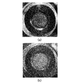
- (A)-(c) are photographs showing a change in contamination on the surface of a dielectric member corresponding to an optical window in an effect confirmation experiment.
- (A) and (b) are photographs showing a change in stain on the surface of a dielectric member corresponding to an optical window in an experiment for confirming the effect on simulated particulate stain.
- FIG. 1 is a diagram showing a schematic configuration of an engine according to an embodiment of the present invention.
- an engine 10 has an intake port 20, an exhaust port 21, a laser spark plug 30 in a cylinder head section 11, and a laser source 40 of a pulse laser introduced into the laser spark plug 30. It has a high-frequency power supply 50 for supplying a high-frequency high-frequency signal to a cleaning device (described later) for the laser spark plug 30, and a control unit 60 for controlling the laser source 40 and the high-frequency power supply 50.
- the intake port 20 is provided in the cylinder head 11, and the intake pipe 24 is connected thereto.
- a vaporizer (not shown) that vaporizes fuel and mixes it with air to form a mixture is connected to the intake pipe 24.
- the exhaust port 21 is provided in the cylinder head 11 and is connected to an exhaust pipe 25.
- the air-fuel mixture is supplied to the combustion chamber 12 from the intake port 20 by opening the intake valve 22 and lowering the piston 13 via the intake pipe 24.
- the air-fuel mixture is compressed by the rise of the piston 13, and combustion occurs by laser ignition.
- soot soot
- gas such as hydrocarbons, acids, aldehydes, phenols, etc.
- water vapor particulate matter generated by combustion from the exhaust port 21 by opening the exhaust valve 23 and raising the piston 13 Substances are exhausted.
- soot and particulate matter adhere to the inner wall facing the combustion chamber 12 and the optical window of the laser spark plug 30.
- the engine 10 may form the air-fuel mixture using a port injection method of injecting fuel into the intake pipe 24 instead of the carburetor, and use a direct injection method of injecting fuel into the combustion chamber 12.
- a mixture may be formed in the combustion chamber 12.
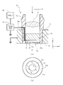
- FIG. 2 is a diagram showing a configuration of the cleaning device according to the embodiment of the present invention, and is a (a) sectional view and (b) a diagram viewed from the combustion chamber side showing a schematic configuration of a laser spark plug. .
- FIG. 2 some of the elements shown in FIG. 1 are omitted for convenience of illustration.
- the laser spark plug 30 is disposed on the cylinder head portion 11, and inside the support fitting 34, a condensing portion 31 for condensing the pulse laser from the laser source 40, An optical window 32 that is exposed to the combustion chamber 12 and separates the light condensing part 31 from the combustion chamber 12 and transmits the condensed pulsed laser.
- a pulse laser is supplied from a laser source 40, is condensed by a condensing unit 31, and is transmitted through an optical window 32 to ignite an air-fuel mixture in the combustion chamber 12.
- the emission timing of the pulse laser is controlled by a control unit 60 connected to the laser source 40 so as to be able to perform signal communication.
- the control unit 60 controls the ignition timing by acquiring information on the crank angle from the crank angle detection unit 61 of the crank 14 interlocked with the piston 13, for example.
- the laser source 40 can use, for example, a YAG laser, but is not particularly limited. Note that the condensing unit 31 may be provided on the laser source 40 side.
- a first electrode 33 is provided in a portion near the surface 32a on the combustion chamber 12 side inside the optical window 32.
- a second electrode 34a is provided so as to be exposed to the combustion chamber 12.
- the second electrode 34a is a portion exposed to the combustion chamber 12 side of the support fitting 34 of the laser spark plug 30.
- the laser spark plug 30 has a shape of a rotating body with respect to an axis extending in the vertical direction of the drawing (parallel to the z direction shown).
- the optical window 32 is formed of a material that transmits the pulse laser and has dielectric properties. Since the temperature of the optical window 32 in the engine 10 rises due to the combustion of the air-fuel mixture, it is preferable that the optical window 32 also has heat resistance. For example, sapphire can be used.
- the optical window 32 has a thickness (z direction) of, for example, 10 mm, and a diameter (xy plane) of, for example, 10 mm.
- the optical window 32 is held by a support bracket.
- the optical window 32 may be composed of two members so as to sandwich the first electrode 33 from above and below in the z direction. For example, a material that is difficult to be molded so that the first electrode 33 is embedded in the optical window 32 can be preferably applied to a case where sapphire is used for the optical window 32, for example.
- the first electrode 33 is formed of a material that transmits a pulse laser and has conductivity.
- the first electrode 33 is a material called a transparent conductive film, and includes indium oxide (InO 2 ), tin oxide (SnO 2 ), and zinc oxide.
- InO 2 indium oxide
- SnO 2 tin oxide
- ZnO zinc oxide
- the first electrode 33 has, for example, a disk shape, a thickness (z direction) of, for example, 1 ⁇ m to 500 ⁇ m, and a diameter (xy plane) of, for example, 3 mm to 30 mm, which is smaller than that of the optical window 32. Preferably, it is formed small.
- the first electrode 33 is disposed at a distance in the range of, for example, 50 ⁇ m to 3000 ⁇ m from the surface 32 a of the optical window 32 on the combustion chamber 12 side, and is covered with the dielectric material of the optical window 32 so as not to be exposed to the combustion chamber 12. Is formed. It is preferable to use sapphire as a dielectric material of the optical window 32 of the combustion chamber 12 covering the first electrode 33.
- the first electrode 33 is preferably arranged at the center of the optical window 32 on a plane perpendicular to the axis on which the pulse laser enters.
- the second electrode 34a is an annular portion exposed on the combustion chamber side of the support fitting 34 of the laser spark plug 30, and is made of a metal material, particularly a material having good heat resistance, such as stainless steel or carbon steel. Can be used.
- the inner diameter of the second electrode 34a is, for example, 3 mm to 30 mm, and is selected according to the diameter of the optical window 32.
- the second electrode 34a is electrically connected to the high-frequency power supply 50. However, since the second electrode 34a is in contact with and electrically connected to the cylinder head 11, the second electrode 34a is grounded via the engine block. It is preferable to configure.
- a wiring 36 is connected to the first electrode 33, and is electrically connected to an external high-frequency power supply 50 through the optical window and the wiring hole 34b of the support bracket.
- the first electrode 33 is electrically connected to the high-frequency power supply 50
- the second electrode 34a is connected to ground (not shown) via the cylinder head 11, for example, and the high-frequency power supply 50 is also grounded (not shown).
- the high-frequency power supply 50 is not particularly limited as long as it can supply a high-frequency or pulsed high-voltage signal.
- the high voltage signal is high frequency or pulsed, and the frequency is preferably set to 0.05 kHz to 1000 kHz from a practical viewpoint in consideration of the power supply device cost, and the voltage is set to 0.1 kV to 100 kV.
- the high voltage signal of the high frequency power supply 50 is controlled by the control unit 60 and applied between the first electrode 33 and the second electrode 34a, so that the surface 32a of the optical window 32 near the first electrode 33 on the combustion chamber 12 side.
- a dielectric barrier discharge PL (Dielectric Barrier Discharge) is generated between the first electrode 34a and the second electrode 34a.
- the wiring hole 34b may be filled with an insulating material.
- the cleaning device is provided inside the optical window 32 for introducing the pulse laser, and the first electrode 33 covered with the dielectric material forming the optical window 32, A second electrode a provided on the periphery and exposed to the surface on the combustion chamber 12 side; and a high-frequency power supply 50 electrically connected between the first electrode 33 and the second electrode a.
- a high frequency or pulsed voltage is applied between the second electrode 34a and the surface 32a close to the first electrode 33 by applying a high frequency or pulsed voltage from the high frequency power supply 50 to the second electrode 34a.
- a dielectric barrier discharge PL is generated along the line (hereinafter, this process is also referred to as “cleaning process”).
- the gas in the combustion chamber 12 is ionized by this dielectric barrier discharge PL, radicals are generated, and an induced airflow is generated.
- the radicals react with the dirt on the surface 32a of the optical window 32, for example, react with deposits or carbon and vaporize, and diffuse into the combustion chamber 12 by the induced airflow, and particulate dirt such as inorganic particles are generated from the surface 32a by the induced airflow. It scatters to 12. Thereby, the surface 32a of the optical window 32 is cleaned. Further, since the first electrode 33 is formed of a material that transmits the pulse laser, a decrease in the pulse laser intensity can be suppressed.
- the cleaning process of the optical window 32 can be performed when the engine is stopped, that is, when the engine is not operating, for example, before the engine is started, after the stopped engine is stopped, or when the engine is operating. be able to.
- the inorganic particles can be removed by an airflow induced by one dielectric barrier discharge having a time width of 100 milliseconds. . For this reason, it can be performed when the engine is stopped, and a cleaning process for removing inorganic particles during operation of the engine is possible. When the cleaning is performed during the operation of the engine, it is preferable to perform the cleaning process during the exhaust stroke, as described below.
- the cleaning process in the exhaust stroke during the operation of the engine, and more preferably to repeatedly perform the cleaning process a plurality of times.
- a dielectric barrier discharge while the piston moves from the bottom dead center to the top dead center in the exhaust stroke of the engine, the surface of the optical window can be cleaned during the operation of the engine.
- Intermediate chemical species that affect the combustion generated by the discharge are discharged and remain in the combustion chamber 12 during the intake stroke, so that the adverse effects of combustion in the compression stroke and the combustion stroke can be reduced or prevented.
- the laser spark plug 30 is disposed so as not to protrude into the combustion chamber 12 and is further mounted on the surface of the cylinder head portion on the combustion chamber side in a flash mount manner. Thereby, the disturbance of the flow of the air-fuel mixture due to the shape of the laser spark plug 30 exposed to the combustion chamber 12 side can be reduced.
- a high-frequency or pulsed voltage is applied between the first electrode 33 and the second electrode 34 a by the high-frequency power supply 50, and the dielectric barrier discharge PL is generated along the surface 32 a of the optical window 32. Then, radicals and induced airflow are generated by the dielectric barrier discharge PL, and the surface and the surface 32a can be removed and cleaned by the radicals and induced airflow.
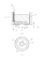
- FIG. 3 is a diagram showing a configuration of a cleaning apparatus according to another embodiment of the present invention, in which (a) a cross-sectional view and (b) a combustion chamber in which an optical window portion of a laser spark plug is enlarged. It is the figure seen from the side.
- the laser spark plug 130 has a structure in which the first electrode 133 is provided inside the optical window 32 such that the first electrode 133 has a plane perpendicular to the axis on which the laser is incident (xy plane).
- the central portion 133a has a shape closer to the surface 32a of the optical window 32 than the surrounding portion 133b.
- the region facing the central portion 133 a of the first electrode 133 and the peripheral portion 133 b of the first electrode 133 on the surface 32 a of the optical window 32 becomes more uniform, the dielectric barrier discharge PL is more uniformly generated from the peripheral portion to the central portion of the surface 32a of the optical window 32, and not only the peripheral portion of the surface 32a but also the central portion. Dirt is easily removed.
- the first electrode 133 is different from the first electrode 33 shown in FIG. 2 in that the shape is different, and the other configuration is the same, for example. Are the same as those in the above-described embodiment, and the description is omitted.
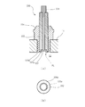
- FIG. 4 is a diagram showing a configuration of a cleaning apparatus according to another embodiment of the present invention, in which (a) a cross-sectional view and (b) a combustion chamber showing an optical window portion of a laser spark plug in an enlarged manner. It is the figure seen from the side.
- the laser spark plug 230 includes a first electrode 233 at a central portion inside the optical window 32 and a third electrode disposed so as to surround the first electrode 233. 235 are provided.
- the third electrode 235 is not electrically connected to the first electrode 233 and the second electrode 34a and is in an electrically floating state.
- the third electrode 235 When a high frequency or pulsed voltage is applied between the first electrode 233 and the second electrode 34a by the high frequency power supply 50 shown in FIGS. 1 and 2, the third electrode 235 is connected to the first electrode 233 and the second electrode 34a. Have an electrostatic interaction between them. At this time, the electrically floating third electrode 235 plays a role as a buried electrode when the dielectric barrier discharge grows from the second electrode 34a toward the center, but the dielectric barrier discharge PL is large. Since the dielectric barrier discharge PL is electrically floating when developed, the effect of inducing a discharge is smaller than that of the first electrode, so that the dielectric barrier discharge PL extends from the peripheral portion to the central portion of the surface 32a of the optical window 32. Occur.
- the diameter of the first electrode 233 can be smaller than the diameter of the first electrode 33 of the embodiment shown in FIG.
- the dielectric barrier discharge PL easily spreads to the center of the surface 32a of the optical window 32, and the center can be easily removed.
- a dielectric barrier discharge was generated by using a dielectric barrier discharge plug (hereinafter, also referred to as a “DBD plug”) to adhere simulated dirt to the surface on the combustion chamber side.
- DBD plug dielectric barrier discharge plug
- FIG. 5 is a (a) sectional view and (b) a view from the combustion chamber side of the dielectric barrier discharge plug used in the effect confirmation experiment.
- the DBD plug 330 includes a center electrode 333a corresponding to a first electrode, an annular electrode 334a corresponding to a second electrode, and an optical A dielectric member 332 corresponding to the window 32, and applying a high-frequency voltage between the center electrode 333a and the annular electrode 334a to apply a dielectric barrier discharge to the surface of the dielectric member 332 exposed to the combustion chamber. Raised.
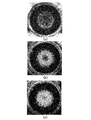
- FIGS. 6A to 6C are photographs showing a change in stain on the surface of the dielectric member corresponding to the optical window in the effect confirmation experiment.
- the DBD plug 330 is attached to the cylinder head of the engine, and the conventional engine is operated by the spark plug, and the surface of the dielectric member 332 (the surface of the optical window 32).
- FIG. 6A shows a state in which soot-like dirt is accumulated in the area (corresponding to 32a).
- the blackest part of the outer ring is the annular electrode 334a, and the inside is the surface of the dielectric member 332.
- FIG. 6B shows a state after applying a high-voltage high-frequency signal having a voltage of 10 kV and a frequency of 15 kHz for 15 seconds between the center electrode 333a and the annular electrode 334a of the DBD plug 330.
- the peripheral portion of the surface of the dielectric member 332, that is, the portion near the annular electrode 334a is white, and it can be seen that the soot-like dirt on the portion is removed.
- FIGS. 7A and 7B are photographs showing a change in contamination on the surface of a dielectric member corresponding to an optical window in an experiment for confirming an effect on simulated particulate contamination.
- the colored porous silica (average particle size: several ⁇ m) is used as a simulated dirt of particulate dirt in the combustion chamber to form the dielectric member 332 of the DBD plug 330. Attached to the surface. This state is shown in FIG.
- the blackest part of the outer ring is the toroidal electrode 334a, the inside of which is the surface of the dielectric member 332, and the surface is coated with black porous silica.
- FIG. 7B shows a state after applying a high-frequency high-frequency signal having a voltage of 10 kV and a frequency of 15 kHz for 100 msec between the center electrode 333a and the annular electrode 334a of the DBD plug 330. According to this, it can be seen that the entire porous silica on the surface of the dielectric member 332 has been removed.
- the laser spark plugs 30, 130, and 230 shown in FIGS. 2 to 4 may incorporate a small laser source, and may omit the condenser 31.
- the present invention can be applied to a gas engine in addition to the gasoline engine described above. Further, the present invention is applied to a semiconductor manufacturing apparatus for introducing a laser or light of a specific wavelength into a chamber and a semiconductor device inspection apparatus.
- a laser annealing apparatus that irradiates an object by introducing a laser to anneal the object, or an apparatus that irradiates an object to be measured in a chamber with an external laser to measure a depth, a thickness, and the like. Needless to say, it can be applied to
Landscapes
- Engineering & Computer Science (AREA)
- Physics & Mathematics (AREA)
- Optics & Photonics (AREA)
- Plasma & Fusion (AREA)
- General Engineering & Computer Science (AREA)
- Chemical & Material Sciences (AREA)
- Combustion & Propulsion (AREA)
- Mechanical Engineering (AREA)
- Spectroscopy & Molecular Physics (AREA)
- Combustion Methods Of Internal-Combustion Engines (AREA)
- Lasers (AREA)
- Plasma Technology (AREA)
- Exhaust Gas After Treatment (AREA)
- Ignition Installations For Internal Combustion Engines (AREA)
Abstract
本開示では、光学窓32の表面を清浄化する装置であって、光学窓の内部に設けられ、光学窓を形成する誘電性材料に覆われる第1の電極33と、光学窓の周囲に設けられ、光学窓の少なくとも一方の側の表面に露出する第2の電極34aと、第1の電極と第2の電極との間に電気的に接続された電源50と、を備え、第1の電極と第2の電極との間に電源により高周波あるいはパルス状の電圧を印加して、光学窓の表面32aに沿って誘電体バリア放電を発生させるように電源50を制御する制御部60と、を備える装置が提供される。
Description
本発明は、装置の光学窓の清浄化技術に関し、特にレーザにより点火するエンジンの光学窓の清浄化に関する技術に関する。
エンジンは、従来、スパークプラグの火花によって混合気を着火して燃焼させることで運転されているが、レーザによる着火も可能であることが実証されてきた。しかし、レーザを燃焼室に導入するレンズや光学窓がエンジンの燃焼による生成物で汚れ、レーザが十分な強度で燃焼室内に届かないため点火できないという主要な問題がある。光学窓の材料を選択して光学窓の温度を高めたり、光学窓の表面にレーザパルスを照射して清浄化する等の対策が検討されている(例えば、非特許文献1参照。)。
S. Gupta, et al. "lens/window-fouling mitigation in laser ignited reciprocating", OPTICS and PHOTONICS International Congress 2018, LIC5‐6, Yokohama, Japan, 2018, April 25-27
本発明は、上述した問題を解決するもので、新規で有用な光学窓の清浄化を行う装置、エンジンおよび清浄化方法を提供する。
本発明の一態様によれば、光学窓の表面を清浄化する装置であって、上記光学窓の内部に設けられ、該光学窓を形成する誘電性材料に覆われる第1の電極と、上記光学窓の周囲に設けられ、該光学窓の少なくとも一方の側の表面に露出する第2の電極と、上記第1の電極と第2の電極との間に電気的に接続された電源と、上記第1の電極と上記第2の電極との間に高周波あるいはパルス状の電圧を印加して、上記光学窓の上記表面に沿って誘電体バリア放電を発生させる上記電源を制御する制御部と、を備える上記装置が提供される。
上記態様によれば、第1の電極と第2の電極との間に高周波あるいはパルス状の電圧を印加して、光学窓の表面に沿って誘電体バリア放電を発生させるように電源を制御部することで、誘電体バリア放電によってラジカルおよび誘起気流が発生し、ラジカルおよび誘起気流によって光学窓の表面の汚れを除去して清浄化することができる。
本発明の他の態様によれば、レーザによって燃焼室内の混合気の着火を行うエンジンであって、レーザ源と、そのレーザ源からレーザを上記燃焼室内に導入する誘電性材料からなる光学窓と、上記態様の光学窓の表面を清浄化する装置と、を備える、上記エンジンが提供される。
上記態様によれば、上記装置によって誘電体バリア放電を発生させ、それによって発生するラジカルおよび誘起気流によってレーザを導入する光学窓の燃焼室側の表面の汚れを除去でき、その結果、レーザによる混合気の点火を安定して行うことができ、エンジンの安定した運転が可能となる。
本発明のその他の態様によれば、レーザによって燃焼室内の混合気の着火を行うエンジンの上記レーザを導入する光学窓の表面を上記態様の光学窓の表面を清浄化する装置によって清浄化する方法であって、上記エンジンの動作時の排気行程中に上記第1の電極と上記第2の電極との間に高周波あるいはパルス状の電圧を印加して、上記光学窓の上記表面に沿って誘電体バリア放電を発生させるように上記電源を制御するステップを含む、上記方法が提供される。
上記態様によれば、エンジンの排気行程中に誘電体バリア放電を発生するように制御することで、エンジンの動作中に誘電体バリア放電によって発生するラジカルおよび誘起気流によって光学窓の燃焼室側の表面の汚れを除去でき、誘電体バリア放電に伴って発生する燃焼に影響を与える中間化学種を排出して安定したエンジンの運転が可能となる。
以下、図面に基づいて本発明の一実施形態を説明する。なお、図面間において共通する要素については同じ符号を付し、その要素の詳細な説明の繰り返しを省略する。
図1は、本発明の一実施形態に係るエンジンの概略構成を示す図である。
図1を参照するに、エンジン10は、シリンダヘッド部11に吸気ポート20と排気ポート21とレーザ点火プラグ30とを有し、さらに、レーザ点火プラグ30に導入されるパルスレーザのレーザ源40とレーザ点火プラグ30の清浄化装置(後述する)に高圧高周波信号を供給する高周波電源50とレーザ源40および高周波電源50を制御する制御部60とを有している。
シリンダヘッド部11において、吸気ポート20はシリンダヘッド部11に設けられ吸気管24が接続される。吸気管24には、燃料を気化して空気と混合し、混合気を形成する気化器(不図示)が接続される。排気ポート21はシリンダヘッド部11に設けられ排気管25が接続される。混合気は、吸気管24を介して吸気バルブ22の開動作およびピストン13の下降により吸気ポート20から燃焼室12に供給される。混合気はピストン13の上昇により圧縮され、レーザ点火により燃焼が発生する。燃焼後は、排気バルブ23の開動作およびピストン13の上昇により排気ポート21から燃焼によって生成されたすす(煤)や、炭化水素類、酸類、アルデヒド類、フェノール類等のガス、水蒸気、粒子状物質等が排気される。この際、燃焼室12に面する内壁やレーザ点火プラグ30の光学窓にすすや粒子状物質が付着する。
なお、エンジン10は、気化器の代わりに吸気管24内に燃料を噴射するポート噴射法を用いて混合気を形成してもよく、燃焼室12内に燃料を噴射する直噴法を用いて燃焼室12内で混合気を形成してもよい。
図2は、本発明の実施形態に係る清浄化装置の構成を示すための図であり、レーザ点火プラグの概略構成を示す(a)断面図および(b)燃焼室側から見た図である。なお、図2では、図1に示されている要素の一部を図示の便宜のため省略している。
図2を図1と合わせて参照するに、レーザ点火プラグ30は、シリンダヘッド部11に配置され、支持金具34の内部に、レーザ源40からのパルスレーザを集光する集光部31と、燃焼室12に露出して集光部31を燃焼室12から隔離し、集光されたパルスレーザを透過する光学窓32とを有する。レーザ源40からパルスレーザが供給され集光部31で集光され光学窓32を透過したパルスレーザが燃焼室12内の混合気を点火する。パルスレーザの出射タイミングは、レーザ源40に信号通信可能に接続される制御部60によって制御される。制御部60は、例えば、ピストン13と連動するクランク14のクランク角検出部61からのクランク角の情報を取得して点火タイミングを制御する。レーザ源40は、例えば、YAGレーザを用いることができるが特に限定されない。なお、集光部31はレーザ源40側に設けてもよい。
光学窓32には、その内部で、燃焼室12側の表面32aに近い部分に第1電極33が設けられる。光学窓32の周囲には、第2電極34aが燃焼室12に露出して設けられる。第2電極34aは、本実施形態ではレーザ点火プラグ30の支持金具34の燃焼室12側に露出する部分である。レーザ点火プラグ30は、紙面の上下方向に延びる(図示するz方向に平行な)軸線に対して回転体の形状を有する。
光学窓32は、パルスレーザを透過すると共に誘電性を有する材料から形成されている。光学窓32は、エンジン10においては、混合気の燃焼により温度が上昇するため、耐熱性も有することが好ましく、例えば、サファイアを用いることができる。光学窓32は、厚さ(z方向)が例えば10mmであり、直径(x-y平面)が例えば10mmである。光学窓32は支持金具に保持される。光学窓32は、第1電極33をz方向の上下から第1電極33を挟むように2つの部材から構成してもよい。例えば、光学窓32に第1電極33を埋め込むように成形し難い材料の場合、例えば光学窓32にサファイアを用いた場合に好ましく適用できる。
第1電極33は、パルスレーザを透過すると共に導電性を有する材料から形成されており、例えば、透明導電膜と称する材料であり、酸化インジウム(InO2)、酸化スズ(SnO2)および酸化亜鉛(ZnO)の少なくとも一つを主成分とする材料、あるいはそれらの混合材料を用いることができ、例えば、ITO(スズをドープしたInO2)、AZO(アルミニウム(Al)をドープしたZnO)、IZO(登録商標)(InO2-ZnO)、GZO(ガリウム(Ga)をドープしたZnO)、ATO(アンチモン(Sb)をドープしたSnO2))などを用いることができる。第1電極33は、例えば円盤状の形状を有し、厚さ(z方向)は例えば、1μm~500μmであり、直径(x-y平面)は、例えば3mm~30mmであり光学窓32よりも小さく形成されることが好ましい。第1電極33は、光学窓32の燃焼室12側の表面32aから例えば50μm~3000μmの範囲の距離に配置されており、燃焼室12に露出しないように光学窓32の誘電性材料により覆うように形成されている。この第1電極33を覆う燃焼室12の光学窓32の誘電性材料にサファイアを用いることが好ましい。第1電極33は、パルスレーザが入光する軸に対して垂直な面において光学窓32の中央部に配置されることが好ましい。
第2電極34aは、本実施形態では、レーザ点火プラグ30の支持金具34の燃焼室側に露出する円環状部分であり、金属材料、特に耐熱性の良好な材料、例えば、ステンレス鋼、炭素鋼を用いることができる。第2電極34aは、内径は例えば3mm~30mmであり光学窓32の直径に応じて選択される。第2電極34aは、高周波電源50に電気的に接続されるが、第2電極34aは、シリンダヘッド部11に接触して電気的に接続されているので、エンジンブロックを介して接地されるように構成することが好ましい。
第1電極33には、配線36が接続され、光学窓および支持金具の配線用孔34bを通じて外部の高周波電源50と電気的に接続される。これにより、第1電極33は高周波電源50に電気的に接続され、第2電極34aは、例えば、シリンダヘッド部11を介してアース(不図示)に接続されており、高周波電源50もアース(不図示)に接続されている。高周波電源50は、高周波あるいはパルス状の高電圧信号を供給可能な電源であれば特に限定されない。この高電圧信号は、高周波あるいはパルス状であり、周波数が、電源の装置コストを考慮した実用的な観点から、0.05kHz~1000kHzに設定されることが好ましく、電圧が0.1kV~100kVに設定されることが好ましい。制御部60により高周波電源50の高電圧信号を制御して第1電極33と第2電極34aとの間に印加して、第1電極33に近接する光学窓32の燃焼室12側の表面32aと第2電極34aとの間に誘電体バリア放電PL(Dielectric Barrier Discharge)が発生する。なお、配線用孔34bは、絶縁材料により充填されてもよい。
このように、本実施形態に係る清浄化装置は、パルスレーザを導入する光学窓32の内部に設けられ、光学窓32を形成する誘電性材料に覆われる第1電極33と、光学窓32の周囲に設けられ燃焼室12側の表面に露出する第2電極34aと、第1電極33と第2電極34aとの間に電気的に接続された高周波電源50を含み、第1電極33と第2電極34aとの間に高周波電源50によって高周波あるいはパルス状の電圧を印加して、燃焼室12に露出している第2電極34aと第1電極33に近い表面32aとの間に、表面32aに沿って誘電体バリア放電PLを発生させる(この処理を以下、「清浄化処理」とも称する)。この誘電体バリア放電PLによって、燃焼室12内の気体がイオン化され、ラジカルが発生し、誘起気流が発生する。ラジカルが光学窓32の表面32aの汚れ、例えば、デポジットやカーボンと反応して気化して誘起気流により燃焼室12に拡散し、無機粒子等の粒子状の汚れが誘起気流によって表面32aから燃焼室12に飛散する。それによって光学窓32の表面32aが清浄化される。また、第1電極33は、パルスレーザを透過する材料から形成されているので、パルスレーザ強度の低下を抑制することができる。
光学窓32の清浄化処理は、エンジン停止時、つまりエンジンが動作していない時、例えば、エンジンの始動前、動作していたエンジンの停止後に行うことができ、あるいは、エンジンの動作時にも行うことができる。
光学窓32の表面32aに付着した無機粒子を除去する場合は、後述する効果確認実験により明らかになるが、100ミリ秒の時間幅の1回の誘電体バリア放電による誘起気流により除去可能である。このことから、エンジン停止時に行うことができ、また、エンジン動作時に無機粒子を除去する清浄化処理が可能である。エンジン動作時に行う場合は、下記に説明するように、排気行程中に清浄化処理を行うことが好ましい。
光学窓32の表面32aに付着したデポジットやカーボンを除去する場合は、後述する効果確認実験により、無機粒子の場合よりも除去しにくいことが明らかになった。このことから、エンジン停止時に比較的長い時間連続して清浄化処理を行うことが好ましい。
また、エンジン動作時の排気行程において清浄化処理を行い、さらに好ましくは繰り返し複数回清浄化処理を行うことがさらに好ましい。エンジンの排気行程におけるピストンが下死点から上死点への移動中に誘電体バリア放電を行うことで光学窓の表面の清浄化をエンジン動作中に行うことができ、その上、誘電体バリア放電に伴って発生する燃焼に影響を与える中間化学種が排出され、吸気行程に燃焼室12内に残存して圧縮行程および燃焼行程における燃焼の悪影響を低減あるいは防止することができる。
レーザ点火プラグ30は、燃焼室12に突出しないように、さらにはシリンダヘッド部の燃焼室側の表面にフラッシュマウント化されて配置されることが好ましい。これにより、レーザ点火プラグ30の燃焼室12側に露出する形状による混合気の流れの乱れを低減できる。
本実施形態によれば、第1電極33と第2電極34aとの間に高周波電源50によって高周波あるいはパルス状の電圧を印加して、光学窓32の表面32aに沿って誘電体バリア放電PLを発生させ、この誘電体バリア放電PLによってラジカルおよび誘起気流が発生されてラジカルおよび誘起気流によって表面32aの汚れを除去して清浄化することができる。
図3は、本発明の他の実施形態に係る清浄化装置の構成を示すための図であり、レーザ点火プラグの光学窓の部分を拡大して示す(a)断面図および(b)燃焼室側から見た図である。図3(a)および(b)を参照するに、レーザ点火プラグ130は、光学窓32の内部に、第1電極133が、レーザの入射する軸に対して垂直な面(x-y面)において、中央部133aの方がその周囲133bよりも光学窓32の表面32aに近接した形状を有する。この構成により、高周波電源50によって配線36を介して高周波電圧が印加されると、光学窓32の表面32aにおいて、第1電極133の中央部133aに対向する領域と第1電極133の周辺部133bに対向する領域の電界強度がより均一になり、光学窓32の表面32aの周辺部から中央部に亘って誘電体バリア放電PLがより均一に発生し、表面32aの周辺部だけでなく中央部の汚れを除去し易くなる。なお、第1電極133は図2に示した第1電極33に対して形状が異なっている点が相違し、それ以外の構成は例えば同様である。を使用して説明した上記の実施形態と同様であるので、説明を省略する。
図4は、本発明のその他の実施形態に係る清浄化装置の構成を示すための図であり、レーザ点火プラグの光学窓の部分を拡大して示す(a)断面図および(b)燃焼室側から見た図である。図4(a)および(b)を参照するに、レーザ点火プラグ230は、光学窓32の内部に、中央部に第1電極233と、第1電極233を囲むように配置された第3電極235とが設けられている。第3電極235は、第1電極233と第2電極34aとは電気的に接続されておらず、電気的に浮いた状態である。
第1電極233と第2電極34aとの間に図1および図2に示した高周波電源50によって高周波あるいはパルス状の電圧を印加すると、第3電極235が第1電極233と第2電極34aとの間で静電的な相互作用をする。このとき電気的には浮遊している第3電極235は誘電体バリア放電が第2電極34aから中央部に向かって成長する初期に埋め込み電極としての役割を果たすが,誘電体バリア放電PLが大きく進展した際には電気的に浮遊していることから,第1電極に比べ放電を誘引する効果が小さくなるため,誘電体バリア放電PLが光学窓32の表面32aの周辺部から中央部に亘って発生する。このため第1電極233の直径を図2に示した実施形態の第1電極33の直径よりも小さくできる。これにより、光学窓32の表面32aの中央部まで誘電体バリア放電PLが広がり易くなり、中央部の汚れの除去がし易くなる。
次に、本発明の実施形態に係る清浄化装置の効果確認の実験について説明する。この実験では、誘電体バリア放電プラグ(以下、「DBDプラグ」とも称する。)を用いてその燃焼室側の表面に模擬汚れを付着させて誘電体バリア放電を発生させた。
図5は、効果確認実験に用いた誘電体バリア放電プラグの(a)断面図および(b)燃焼室側から見た図である。図5(a)および(b)を先の図2と合わせて参照するに、DBDプラグ330は、第1電極に相当する中心電極333aと、第2電極に相当する円環状電極334aと、光学窓32に相当する誘電体部材332とを有し、中心電極333aと円環状電極334aとの間に高周波電圧を印加することで燃焼室に露出する誘電体部材332の表面に誘電体バリア放電を発生させた。
[効果確認実験1:燃焼室内のすす状の汚れ]
図6(a)~(c)は効果確認実験における光学窓に相当する誘電体部材の表面の汚れの変化を示す写真である。図6(a)~(c)を参照するに、DBDプラグ330をエンジンのシリンダヘッド部に取り付け、点火プラグにより従来のエンジンの運転を行って、誘電体部材332の表面(光学窓32の表面32aに相当)にすす状の汚れを蓄積させた状態を図6(a)に示している。外環の最も黒い部分が円環状電極334aでありその内側が誘電体部材332の表面である。
図6(a)~(c)は効果確認実験における光学窓に相当する誘電体部材の表面の汚れの変化を示す写真である。図6(a)~(c)を参照するに、DBDプラグ330をエンジンのシリンダヘッド部に取り付け、点火プラグにより従来のエンジンの運転を行って、誘電体部材332の表面(光学窓32の表面32aに相当)にすす状の汚れを蓄積させた状態を図6(a)に示している。外環の最も黒い部分が円環状電極334aでありその内側が誘電体部材332の表面である。
次いで、DBDプラグ330の中心電極333aと円環状電極334aとの間に電圧10kV、周波数15kHzの高圧高周波信号を15秒間印加した後の状態を図6(b)に示している。これによれば、誘電体部材332の表面の周辺部つまり円環状電極334aに近い部分が白くなっており、その部分のすす状の汚れが除去されていることが分かる。
次いで、DBDプラグ330の中心電極333aと円環状電極334aとの間に電圧10kV、周波数15kHzの正弦波をバースト20m秒幅のバースト状としてバーストの周波数を5Hzとした高圧高周波信号を18分間印加した後の状態を図6(c)に示している。これによれば、誘電体部材332の表面のほぼ全体の汚れが除去されていることが分かる。
以上のことから、DBDプラグ330による誘電体バリア放電により誘電体部材332の表面の燃焼室内のすす状の汚れが除去できることが分かった。
[効果確認実験2:粒子状の模擬汚れ]
図7(a)および(b)は、粒子状の模擬汚れに対する効果確認実験における光学窓に相当する誘電体部材の表面の汚れの変化を示す写真である。図7(a)および(b)を参照するに、着色した多孔質シリカ(平均粒径:数μm)を燃焼室内での粒子状の汚れの模擬汚れとして、DBDプラグ330の誘電体部材332の表面に付着させた。この状態を図7(a)に示している。外環の最も黒い部分が円環状電極334aでありその内側が誘電体部材332の表面であり、その表面に黒っぽく多孔質シリカが付着している。
図7(a)および(b)は、粒子状の模擬汚れに対する効果確認実験における光学窓に相当する誘電体部材の表面の汚れの変化を示す写真である。図7(a)および(b)を参照するに、着色した多孔質シリカ(平均粒径:数μm)を燃焼室内での粒子状の汚れの模擬汚れとして、DBDプラグ330の誘電体部材332の表面に付着させた。この状態を図7(a)に示している。外環の最も黒い部分が円環状電極334aでありその内側が誘電体部材332の表面であり、その表面に黒っぽく多孔質シリカが付着している。
次いで、DBDプラグ330の中心電極333aと円環状電極334aとの間に電圧10kV、周波数15kHzの高圧高周波信号を100m秒間印加した後の状態を図7(b)に示している。これによれば、誘電体部材332の表面の全体の多孔質シリカが除去されていることが分かる。
以上のことから、DBDプラグ330による誘電体バリア放電により誘電体部材332の表面の燃焼室内の粒子状の汚れが除去できることが分かった。
以上、本発明の好ましい実施形態について詳述したが、本発明は係る特定の実施形態に限定されるものではなく、特許請求の範囲に記載された本発明の範囲内において、種々の変形・変更が可能である。図2~4で示したレーザ点火プラグ30、130、230は、小型のレーザ源を組み込んでもよく、また、集光部31は省略してもよい。
本発明は、上述したガソリンエンジンに加えてガスエンジンに適用することができ、さらに、本発明は、チャンバー内にレーザあるいは特定の波長の光を導入する半導体製造装置および半導体装置の検査装置に適用することができ、例えば、レーザを導入して被処理物に照射しアニールを行うレーザアニール処理装置や、チャンバー内の被測定物に外部からレーザを照射して深さや厚さ等を測定する装置に適用可能できることは言うまでもない。
なお、以上の説明に関してさらに実施形態として以下の付記を開示する。
(付記1)レーザを光学窓から導入して燃焼室内の混合気の着火を行うエンジンの光学窓の表面を清浄化する装置であって、
前記燃焼室側の光学窓の表面に該光学窓を形成する誘電性材料に覆われる第1の電極と、
前記光学窓の周囲に設けられ、該光学窓の前記燃焼室側の表面に露出する第2の電極と、
前記第1の電極と第2の電極との間に電気的に接続された電源と、
前記第1の電極と前記第2の電極との間に高周波あるいはパルス状の電圧を印加して、前記燃焼室側の光学窓の前記表面に沿って誘電体バリア放電を発生させるように前記電源を制御する制御部と、を備える前記装置。
(付記1)レーザを光学窓から導入して燃焼室内の混合気の着火を行うエンジンの光学窓の表面を清浄化する装置であって、
前記燃焼室側の光学窓の表面に該光学窓を形成する誘電性材料に覆われる第1の電極と、
前記光学窓の周囲に設けられ、該光学窓の前記燃焼室側の表面に露出する第2の電極と、
前記第1の電極と第2の電極との間に電気的に接続された電源と、
前記第1の電極と前記第2の電極との間に高周波あるいはパルス状の電圧を印加して、前記燃焼室側の光学窓の前記表面に沿って誘電体バリア放電を発生させるように前記電源を制御する制御部と、を備える前記装置。
10 エンジン
11 シリンダヘッド部
11a 内壁
12 燃焼室
13 ピストン
20 吸気ポート
21 排気ポート
30,130,230 レーザ点火プラグ
31 集光部
32 光学窓
32a 光学窓の表面
33,133,233 第1電極
34 支持金具
34a 第2電極
34b 配線用孔
36 配線
50 高周波電源
60 制御部
61 クランク角検出部
235 第3電極
11 シリンダヘッド部
11a 内壁
12 燃焼室
13 ピストン
20 吸気ポート
21 排気ポート
30,130,230 レーザ点火プラグ
31 集光部
32 光学窓
32a 光学窓の表面
33,133,233 第1電極
34 支持金具
34a 第2電極
34b 配線用孔
36 配線
50 高周波電源
60 制御部
61 クランク角検出部
235 第3電極
Claims (14)
- 光学窓の表面を清浄化する装置であって、
前記光学窓の内部に設けられ、該光学窓を形成する誘電性材料に覆われる第1の電極と、
前記光学窓の周囲に設けられ、該光学窓の少なくとも一方の側の表面に露出する第2の電極と、
前記第1の電極と第2の電極との間に電気的に接続された電源と、
前記第1の電極と前記第2の電極との間に高周波あるいはパルス状の電圧を印加して、前記光学窓の前記表面に沿って誘電体バリア放電を発生させるように前記電源を制御する制御部と、を備える前記装置。 - 前記光学窓は、レーザにより点火するエンジンに配置され、
前記光学窓の燃焼室側の表面の内部に前記第1の電極が配置され、該燃焼室に露出して前記第2の電極が配置され、前記光学窓の燃焼室側の表面に沿って前記誘電体バリア放電を発生させる、請求項1記載の装置。 - 前記第1の電極は、前記レーザの入射する軸に対して垂直な面において前記光学窓の中央部に配置されてなる、請求項2記載の装置。
- 前記第1の電極は、前記中央部がその周囲よりも前記光学窓の前記表面に近接した形状を有する、請求項3記載の装置。
- 前記第1の電極は、前記光学窓の前記表面に平行に延在する、請求項1~4のうちいずれか一項記載の装置。
- 前記光学窓の内部に前記第1の電極を囲むように配置され、前記第1および第2の電極とは電気的に接続されていない第3の電極をさらに備える、請求項1~5のうちいずれか一項記載の装置。
- 前記光学窓は円盤状であり、前記第2の電極は該光学窓を囲む円環状である、請求項1~6のうちいずれか一項記載の装置。
- 前記光学窓は、その厚さ方向に配置された2つの光学窓部材からなり、
前記第1の電極が、前記2つの光学窓部材に挟まれてなる、請求項1~7のうちいずれか一項記載の装置。 - 前記第1の電極は、酸化スズ(SnO2)および酸化亜鉛(ZnO)の少なくとも一つを主成分とする材料、あるいはそれらの混合材料からなる、請求項1~8のうちいずれか一項記載の装置。
- 前記高周波あるいはパルス状の電圧の周波数は、0.05kHz~1000kHzに設定される、請求項1~9のうちいずれか一項記載の装置。
- 前記高周波あるいはパルス状の電圧は、0.1kV~100kVに設定される、請求項1~10のうちいずれか一項記載の装置。
- レーザを光学窓から導入して燃焼室内の混合気の着火を行うエンジンの光学窓の表面を清浄化する装置であって、
前記燃焼室側の光学窓の表面に該光学窓を形成する誘電性材料に覆われる第1の電極と、
前記光学窓の周囲に設けられ、該光学窓の前記燃焼室側の表面に露出する第2の電極と、
前記第1の電極と第2の電極との間に電気的に接続された電源と、
前記第1の電極と前記第2の電極との間に高周波あるいはパルス状の電圧を印加して、前記燃焼室側の光学窓の前記表面に沿って誘電体バリア放電を発生させるように前記電源を制御する制御部と、を備える前記装置。 - レーザによって燃焼室内の混合気の着火を行うエンジンであって、
レーザ源と、
前記レーザ源からレーザを前記燃焼室内に導入する誘電性材料からなる光学窓と、
請求項1~12のうちいずれか一項記載の装置と、
を備える、前記エンジン。 - レーザによって燃焼室内の混合気の着火を行うエンジンの該レーザを導入する光学窓の表面を請求項1~12のうちいずれか一項記載の装置によって清浄化する方法であって、
前記エンジンの動作時の排気行程中に前記第1の電極と前記第2の電極との間に高周波あるいはパルス状の電圧を印加して、前記光学窓の前記表面に沿って誘電体バリア放電を発生させるように前記電源を制御するステップを含む、前記方法。
Priority Applications (4)
| Application Number | Priority Date | Filing Date | Title |
|---|---|---|---|
| CN201980042244.7A CN112292522B (zh) | 2018-06-27 | 2019-06-19 | 光学窗口的净化装置、发动机及其光学窗口的净化方法 |
| JP2020527442A JP6980319B2 (ja) | 2018-06-27 | 2019-06-19 | 光学窓の清浄化装置、エンジンおよびその光学窓の清浄化方法 |
| US17/255,924 US11389840B2 (en) | 2018-06-27 | 2019-06-19 | Cleaning apparatus for optical window, engine, and method for cleaning optical window of engine |
| DE112019003242.9T DE112019003242B4 (de) | 2018-06-27 | 2019-06-19 | Reinigungsvorrichtung für optisches Fenster, Motor und Verfahren zum Reinigen des optischen Fensters eines Motors |
Applications Claiming Priority (2)
| Application Number | Priority Date | Filing Date | Title |
|---|---|---|---|
| JP2018121998 | 2018-06-27 | ||
| JP2018-121998 | 2018-06-27 |
Publications (1)
| Publication Number | Publication Date |
|---|---|
| WO2020004181A1 true WO2020004181A1 (ja) | 2020-01-02 |
Family
ID=68987097
Family Applications (1)
| Application Number | Title | Priority Date | Filing Date |
|---|---|---|---|
| PCT/JP2019/024314 Ceased WO2020004181A1 (ja) | 2018-06-27 | 2019-06-19 | 光学窓の清浄化装置、エンジンおよびその光学窓の清浄化方法 |
Country Status (5)
| Country | Link |
|---|---|
| US (1) | US11389840B2 (ja) |
| JP (1) | JP6980319B2 (ja) |
| CN (1) | CN112292522B (ja) |
| DE (1) | DE112019003242B4 (ja) |
| WO (1) | WO2020004181A1 (ja) |
Cited By (1)
| Publication number | Priority date | Publication date | Assignee | Title |
|---|---|---|---|---|
| CN113666462A (zh) * | 2021-05-21 | 2021-11-19 | 中国科学院海洋研究所 | 一种双电极式海洋检测设备防污窗口组件 |
Families Citing this family (1)
| Publication number | Priority date | Publication date | Assignee | Title |
|---|---|---|---|---|
| CN111552211B (zh) * | 2020-05-18 | 2021-03-09 | 北京理工大学 | 一种用于光学发动机激光测试的同步控制方法及系统 |
Citations (3)
| Publication number | Priority date | Publication date | Assignee | Title |
|---|---|---|---|---|
| JPH08165978A (ja) * | 1994-12-14 | 1996-06-25 | Mitsubishi Heavy Ind Ltd | レーザ着火方法 |
| JP2008002280A (ja) * | 2006-06-20 | 2008-01-10 | Kawasaki Heavy Ind Ltd | 光学窓洗浄容易なレーザ着火装置 |
| WO2016093214A1 (ja) * | 2014-12-08 | 2016-06-16 | 株式会社デンソー | 点火装置並びにこれに用いられる超親水膜の製造方法 |
Family Cites Families (11)
| Publication number | Priority date | Publication date | Assignee | Title |
|---|---|---|---|---|
| JPS58165578A (ja) * | 1982-03-24 | 1983-09-30 | Toyota Motor Corp | 内燃機関の点火方法 |
| JP3195508B2 (ja) * | 1995-01-26 | 2001-08-06 | 松下電工株式会社 | レーザ処理装置及びレーザ処理方法 |
| JPH09250438A (ja) * | 1996-03-14 | 1997-09-22 | Mitsubishi Heavy Ind Ltd | エンジン着火装置 |
| JP4860336B2 (ja) * | 2006-04-24 | 2012-01-25 | バキュームプロダクツ株式会社 | 真空処理装置 |
| AT505048A1 (de) | 2007-03-22 | 2008-10-15 | Reinhard Mag Dipl Ing Dr Posch | Fenster |
| AT505766B1 (de) * | 2007-12-19 | 2009-04-15 | Ge Jenbacher Gmbh & Co Ohg | Vorrichtung zum einkoppeln von laserlicht in einen brennraum einer brennkraftmaschine |
| US8648322B2 (en) * | 2008-10-31 | 2014-02-11 | Cummins Inc. | Optical sensing in an adverse environment |
| DE102012005109A1 (de) | 2012-03-14 | 2013-09-19 | Fraunhofer-Gesellschaft zur Förderung der angewandten Forschung e.V. | Oberflächenreinigungsvorrichtung |
| JP6478509B2 (ja) * | 2014-07-31 | 2019-03-06 | 株式会社Soken | レーザ点火装置 |
| JP6631201B2 (ja) | 2014-12-08 | 2020-01-15 | 株式会社デンソー | 点火装置並びにこれに用いられる超親水膜の製造方法 |
| WO2017153898A1 (en) * | 2016-03-07 | 2017-09-14 | King Abdullah University Of Science And Technology | Non thermal plasma surface cleaner and method of use |
-
2019
- 2019-06-19 US US17/255,924 patent/US11389840B2/en active Active
- 2019-06-19 JP JP2020527442A patent/JP6980319B2/ja active Active
- 2019-06-19 DE DE112019003242.9T patent/DE112019003242B4/de active Active
- 2019-06-19 WO PCT/JP2019/024314 patent/WO2020004181A1/ja not_active Ceased
- 2019-06-19 CN CN201980042244.7A patent/CN112292522B/zh active Active
Patent Citations (3)
| Publication number | Priority date | Publication date | Assignee | Title |
|---|---|---|---|---|
| JPH08165978A (ja) * | 1994-12-14 | 1996-06-25 | Mitsubishi Heavy Ind Ltd | レーザ着火方法 |
| JP2008002280A (ja) * | 2006-06-20 | 2008-01-10 | Kawasaki Heavy Ind Ltd | 光学窓洗浄容易なレーザ着火装置 |
| WO2016093214A1 (ja) * | 2014-12-08 | 2016-06-16 | 株式会社デンソー | 点火装置並びにこれに用いられる超親水膜の製造方法 |
Cited By (1)
| Publication number | Priority date | Publication date | Assignee | Title |
|---|---|---|---|---|
| CN113666462A (zh) * | 2021-05-21 | 2021-11-19 | 中国科学院海洋研究所 | 一种双电极式海洋检测设备防污窗口组件 |
Also Published As
| Publication number | Publication date |
|---|---|
| DE112019003242T5 (de) | 2021-04-01 |
| US11389840B2 (en) | 2022-07-19 |
| CN112292522B (zh) | 2022-06-03 |
| US20210260632A1 (en) | 2021-08-26 |
| JPWO2020004181A1 (ja) | 2021-05-13 |
| DE112019003242B4 (de) | 2024-11-28 |
| JP6980319B2 (ja) | 2021-12-15 |
| CN112292522A (zh) | 2021-01-29 |
Similar Documents
| Publication | Publication Date | Title |
|---|---|---|
| KR101892627B1 (ko) | 비대칭 점화 팁을 구비한 코로나 점화장치 | |
| US20060081566A1 (en) | Method and arrangement for controlling a glow discharge plasma under atmospheric conditions | |
| US5469013A (en) | Large discharge-volume, silent discharge spark plug | |
| JP6980319B2 (ja) | 光学窓の清浄化装置、エンジンおよびその光学窓の清浄化方法 | |
| JP5860202B2 (ja) | 内燃エンジン用レーザー点火システム及び方法 | |
| WO2006011950A3 (en) | Pre-chamber spark plug | |
| CN1898468A (zh) | 用来点燃发动机的燃烧室内的燃料的方法、所属装置及发动机 | |
| CN109340019A (zh) | 一种点火器工作方法 | |
| JP2016109128A (ja) | 点火装置並びにこれに用いられる超親水膜の製造方法 | |
| JP5393792B2 (ja) | 内燃機関用無線周波数点火システムにおけるイオン化電流測定デバイス | |
| CN107218125B (zh) | 一种用于等离子体强化燃烧的二冲程内燃机电极组件 | |
| CN101749164B (zh) | 内燃机 | |
| WO2017082300A1 (ja) | 火花放電着火促進方法、火花放電着火促進装置、および火花放電着火促進装置付きエンジン | |
| JP5439681B2 (ja) | デポジットの除去装置及び燃焼機関 | |
| Yong et al. | Electrical breakdown characteristics of soil under dc high voltage | |
| JP2000179412A (ja) | 内燃機関 | |
| CN113796163A (zh) | 等离子体点火方法和等离子体生成装置 | |
| JPH08165978A (ja) | レーザ着火方法 | |
| KR100251905B1 (ko) | 레이저를 이용한 점화장치 | |
| CN1061505A (zh) | 发生和点燃等离子体的方法和装置 | |
| KR101634094B1 (ko) | 플라즈마 제트를 이용한 희박 연소 시스템 | |
| RU2719762C1 (ru) | Способ электрической обработки топлива | |
| SU1760587A1 (ru) | Свеча зажигани дл двигател внутреннего сгорани | |
| JP2008258077A (ja) | 点火プラグ | |
| JP2004068800A (ja) | 自動車の低燃費化方法 |
Legal Events
| Date | Code | Title | Description |
|---|---|---|---|
| 121 | Ep: the epo has been informed by wipo that ep was designated in this application |
Ref document number: 19826910 Country of ref document: EP Kind code of ref document: A1 |
|
| ENP | Entry into the national phase |
Ref document number: 2020527442 Country of ref document: JP Kind code of ref document: A |
|
| 122 | Ep: pct application non-entry in european phase |
Ref document number: 19826910 Country of ref document: EP Kind code of ref document: A1 |