WO2020004155A1 - 識別媒体、真正性判定方法、及び物品 - Google Patents
識別媒体、真正性判定方法、及び物品 Download PDFInfo
- Publication number
- WO2020004155A1 WO2020004155A1 PCT/JP2019/024162 JP2019024162W WO2020004155A1 WO 2020004155 A1 WO2020004155 A1 WO 2020004155A1 JP 2019024162 W JP2019024162 W JP 2019024162W WO 2020004155 A1 WO2020004155 A1 WO 2020004155A1
- Authority
- WO
- WIPO (PCT)
- Prior art keywords
- layer
- identification medium
- polarized light
- circularly polarized
- light
- Prior art date
Links
- 238000000034 method Methods 0.000 title claims description 37
- 229920005989 resin Polymers 0.000 claims description 145
- 239000011347 resin Substances 0.000 claims description 145
- 230000003098 cholesteric effect Effects 0.000 claims description 144
- 239000010410 layer Substances 0.000 description 712
- 239000000203 mixture Substances 0.000 description 54
- 150000001875 compounds Chemical class 0.000 description 53
- 239000004986 Cholesteric liquid crystals (ChLC) Substances 0.000 description 38
- 239000003973 paint Substances 0.000 description 38
- 239000000463 material Substances 0.000 description 34
- BZHJMEDXRYGGRV-UHFFFAOYSA-N Vinyl chloride Chemical compound ClC=C BZHJMEDXRYGGRV-UHFFFAOYSA-N 0.000 description 33
- 239000004973 liquid crystal related substance Substances 0.000 description 26
- -1 acryl Chemical group 0.000 description 21
- 239000000853 adhesive Substances 0.000 description 21
- 230000001070 adhesive effect Effects 0.000 description 21
- 239000007788 liquid Substances 0.000 description 21
- 239000012790 adhesive layer Substances 0.000 description 16
- 125000000217 alkyl group Chemical group 0.000 description 16
- 125000004432 carbon atom Chemical group C* 0.000 description 16
- 238000004519 manufacturing process Methods 0.000 description 15
- 238000005259 measurement Methods 0.000 description 14
- 229920000642 polymer Polymers 0.000 description 14
- 238000007650 screen-printing Methods 0.000 description 14
- 239000011295 pitch Substances 0.000 description 12
- 239000004094 surface-active agent Substances 0.000 description 12
- 229920002799 BoPET Polymers 0.000 description 11
- 238000007639 printing Methods 0.000 description 11
- UWCWUCKPEYNDNV-LBPRGKRZSA-N 2,6-dimethyl-n-[[(2s)-pyrrolidin-2-yl]methyl]aniline Chemical compound CC1=CC=CC(C)=C1NC[C@H]1NCCC1 UWCWUCKPEYNDNV-LBPRGKRZSA-N 0.000 description 10
- 238000010438 heat treatment Methods 0.000 description 10
- PCTMTFRHKVHKIS-BMFZQQSSSA-N (1s,3r,4e,6e,8e,10e,12e,14e,16e,18s,19r,20r,21s,25r,27r,30r,31r,33s,35r,37s,38r)-3-[(2r,3s,4s,5s,6r)-4-amino-3,5-dihydroxy-6-methyloxan-2-yl]oxy-19,25,27,30,31,33,35,37-octahydroxy-18,20,21-trimethyl-23-oxo-22,39-dioxabicyclo[33.3.1]nonatriaconta-4,6,8,10 Chemical compound C1C=C2C[C@@H](OS(O)(=O)=O)CC[C@]2(C)[C@@H]2[C@@H]1[C@@H]1CC[C@H]([C@H](C)CCCC(C)C)[C@@]1(C)CC2.O[C@H]1[C@@H](N)[C@H](O)[C@@H](C)O[C@H]1O[C@H]1/C=C/C=C/C=C/C=C/C=C/C=C/C=C/[C@H](C)[C@@H](O)[C@@H](C)[C@H](C)OC(=O)C[C@H](O)C[C@H](O)CC[C@@H](O)[C@H](O)C[C@H](O)C[C@](O)(C[C@H](O)[C@H]2C(O)=O)O[C@H]2C1 PCTMTFRHKVHKIS-BMFZQQSSSA-N 0.000 description 9
- 239000011230 binding agent Substances 0.000 description 9
- 230000000052 comparative effect Effects 0.000 description 9
- 239000003431 cross linking reagent Substances 0.000 description 9
- 238000011156 evaluation Methods 0.000 description 9
- 239000002904 solvent Substances 0.000 description 9
- 238000002834 transmittance Methods 0.000 description 9
- 230000003287 optical effect Effects 0.000 description 8
- 125000003277 amino group Chemical group 0.000 description 7
- 125000003178 carboxy group Chemical group [H]OC(*)=O 0.000 description 7
- 238000001035 drying Methods 0.000 description 7
- 125000005843 halogen group Chemical group 0.000 description 7
- 238000001228 spectrum Methods 0.000 description 7
- 125000001424 substituent group Chemical group 0.000 description 7
- NIXOWILDQLNWCW-UHFFFAOYSA-M Acrylate Chemical compound [O-]C(=O)C=C NIXOWILDQLNWCW-UHFFFAOYSA-M 0.000 description 6
- 239000004820 Pressure-sensitive adhesive Substances 0.000 description 6
- 125000004093 cyano group Chemical group *C#N 0.000 description 6
- 230000001747 exhibiting effect Effects 0.000 description 6
- 125000002887 hydroxy group Chemical group [H]O* 0.000 description 6
- 125000003700 epoxy group Chemical group 0.000 description 5
- 239000002245 particle Substances 0.000 description 5
- 125000003396 thiol group Chemical group [H]S* 0.000 description 5
- 230000009102 absorption Effects 0.000 description 4
- 238000010521 absorption reaction Methods 0.000 description 4
- 125000002947 alkylene group Chemical group 0.000 description 4
- 230000014509 gene expression Effects 0.000 description 4
- IQPQWNKOIGAROB-UHFFFAOYSA-N isocyanate group Chemical group [N-]=C=O IQPQWNKOIGAROB-UHFFFAOYSA-N 0.000 description 4
- 125000001140 1,4-phenylene group Chemical group [H]C1=C([H])C([*:2])=C([H])C([H])=C1[*:1] 0.000 description 3
- 125000004959 2,6-naphthylene group Chemical group [H]C1=C([H])C2=C([H])C([*:1])=C([H])C([H])=C2C([H])=C1[*:2] 0.000 description 3
- 239000004593 Epoxy Substances 0.000 description 3
- 230000000694 effects Effects 0.000 description 3
- 125000004435 hydrogen atom Chemical group [H]* 0.000 description 3
- 239000012948 isocyanate Substances 0.000 description 3
- 239000000178 monomer Substances 0.000 description 3
- 239000012299 nitrogen atmosphere Substances 0.000 description 3
- 239000003960 organic solvent Substances 0.000 description 3
- 230000010287 polarization Effects 0.000 description 3
- 238000006116 polymerization reaction Methods 0.000 description 3
- 230000000379 polymerizing effect Effects 0.000 description 3
- 229920000098 polyolefin Polymers 0.000 description 3
- 230000008569 process Effects 0.000 description 3
- 239000005268 rod-like liquid crystal Substances 0.000 description 3
- 239000002356 single layer Substances 0.000 description 3
- 238000000870 ultraviolet spectroscopy Methods 0.000 description 3
- 125000004955 1,4-cyclohexylene group Chemical group [H]C1([H])C([H])([H])C([H])([*:1])C([H])([H])C([H])([H])C1([H])[*:2] 0.000 description 2
- 125000003504 2-oxazolinyl group Chemical group O1C(=NCC1)* 0.000 description 2
- VVBLNCFGVYUYGU-UHFFFAOYSA-N 4,4'-Bis(dimethylamino)benzophenone Chemical compound C1=CC(N(C)C)=CC=C1C(=O)C1=CC=C(N(C)C)C=C1 VVBLNCFGVYUYGU-UHFFFAOYSA-N 0.000 description 2
- KWOLFJPFCHCOCG-UHFFFAOYSA-N Acetophenone Chemical compound CC(=O)C1=CC=CC=C1 KWOLFJPFCHCOCG-UHFFFAOYSA-N 0.000 description 2
- 239000004925 Acrylic resin Substances 0.000 description 2
- 229920000178 Acrylic resin Polymers 0.000 description 2
- GUUVPOWQJOLRAS-UHFFFAOYSA-N Diphenyl disulfide Chemical compound C=1C=CC=CC=1SSC1=CC=CC=C1 GUUVPOWQJOLRAS-UHFFFAOYSA-N 0.000 description 2
- RWNKSTSCBHKHTB-UHFFFAOYSA-N Hexachloro-1,3-butadiene Chemical compound ClC(Cl)=C(Cl)C(Cl)=C(Cl)Cl RWNKSTSCBHKHTB-UHFFFAOYSA-N 0.000 description 2
- 239000005057 Hexamethylene diisocyanate Substances 0.000 description 2
- UFWIBTONFRDIAS-UHFFFAOYSA-N Naphthalene Chemical compound C1=CC=CC2=CC=CC=C21 UFWIBTONFRDIAS-UHFFFAOYSA-N 0.000 description 2
- 239000004952 Polyamide Substances 0.000 description 2
- 239000004642 Polyimide Substances 0.000 description 2
- 239000004793 Polystyrene Substances 0.000 description 2
- 239000004372 Polyvinyl alcohol Substances 0.000 description 2
- 239000002253 acid Substances 0.000 description 2
- 150000001252 acrylic acid derivatives Chemical class 0.000 description 2
- NIXOWILDQLNWCW-UHFFFAOYSA-N acrylic acid group Chemical group C(C=C)(=O)O NIXOWILDQLNWCW-UHFFFAOYSA-N 0.000 description 2
- 230000001154 acute effect Effects 0.000 description 2
- 125000002723 alicyclic group Chemical group 0.000 description 2
- 125000003545 alkoxy group Chemical group 0.000 description 2
- MWPLVEDNUUSJAV-UHFFFAOYSA-N anthracene Chemical compound C1=CC=CC2=CC3=CC=CC=C3C=C21 MWPLVEDNUUSJAV-UHFFFAOYSA-N 0.000 description 2
- 239000003963 antioxidant agent Substances 0.000 description 2
- 239000012298 atmosphere Substances 0.000 description 2
- ISAOCJYIOMOJEB-UHFFFAOYSA-N benzoin Chemical compound C=1C=CC=CC=1C(O)C(=O)C1=CC=CC=C1 ISAOCJYIOMOJEB-UHFFFAOYSA-N 0.000 description 2
- 229910052799 carbon Inorganic materials 0.000 description 2
- 239000003054 catalyst Substances 0.000 description 2
- 238000006243 chemical reaction Methods 0.000 description 2
- 239000003153 chemical reaction reagent Substances 0.000 description 2
- 238000000576 coating method Methods 0.000 description 2
- 229940125904 compound 1 Drugs 0.000 description 2
- 229940125782 compound 2 Drugs 0.000 description 2
- 238000003851 corona treatment Methods 0.000 description 2
- 238000004132 cross linking Methods 0.000 description 2
- BGTOWKSIORTVQH-UHFFFAOYSA-N cyclopentanone Chemical compound O=C1CCCC1 BGTOWKSIORTVQH-UHFFFAOYSA-N 0.000 description 2
- 238000013461 design Methods 0.000 description 2
- ZUOUZKKEUPVFJK-UHFFFAOYSA-N diphenyl Chemical compound C1=CC=CC=C1C1=CC=CC=C1 ZUOUZKKEUPVFJK-UHFFFAOYSA-N 0.000 description 2
- 238000007756 gravure coating Methods 0.000 description 2
- RRAMGCGOFNQTLD-UHFFFAOYSA-N hexamethylene diisocyanate Chemical compound O=C=NCCCCCCN=C=O RRAMGCGOFNQTLD-UHFFFAOYSA-N 0.000 description 2
- 125000001165 hydrophobic group Chemical group 0.000 description 2
- 239000003999 initiator Substances 0.000 description 2
- 230000001678 irradiating effect Effects 0.000 description 2
- 150000002513 isocyanates Chemical class 0.000 description 2
- ZFSLODLOARCGLH-UHFFFAOYSA-N isocyanuric acid Chemical class OC1=NC(O)=NC(O)=N1 ZFSLODLOARCGLH-UHFFFAOYSA-N 0.000 description 2
- 150000002576 ketones Chemical class 0.000 description 2
- 239000004611 light stabiliser Substances 0.000 description 2
- 238000002156 mixing Methods 0.000 description 2
- 150000004767 nitrides Chemical class 0.000 description 2
- WXZMFSXDPGVJKK-UHFFFAOYSA-N pentaerythritol Chemical compound OCC(CO)(CO)CO WXZMFSXDPGVJKK-UHFFFAOYSA-N 0.000 description 2
- 125000001997 phenyl group Chemical group [H]C1=C([H])C([H])=C(*)C([H])=C1[H] 0.000 description 2
- 239000000049 pigment Substances 0.000 description 2
- 239000002985 plastic film Substances 0.000 description 2
- 229920000058 polyacrylate Polymers 0.000 description 2
- 229920002647 polyamide Polymers 0.000 description 2
- 229920000515 polycarbonate Polymers 0.000 description 2
- 239000004417 polycarbonate Substances 0.000 description 2
- 229920000728 polyester Polymers 0.000 description 2
- 229920000139 polyethylene terephthalate Polymers 0.000 description 2
- 239000005020 polyethylene terephthalate Substances 0.000 description 2
- 229920001721 polyimide Polymers 0.000 description 2
- 229920002451 polyvinyl alcohol Polymers 0.000 description 2
- 238000012545 processing Methods 0.000 description 2
- 239000000243 solution Substances 0.000 description 2
- 239000000758 substrate Substances 0.000 description 2
- 125000000446 sulfanediyl group Chemical group *S* 0.000 description 2
- 230000000007 visual effect Effects 0.000 description 2
- PSQYTAPXSHCGMF-BQYQJAHWSA-N β-ionone Chemical compound CC(=O)\C=C\C1=C(C)CCCC1(C)C PSQYTAPXSHCGMF-BQYQJAHWSA-N 0.000 description 2
- SFEOKXHPFMOVRM-UHFFFAOYSA-N (+)-(S)-gamma-ionone Natural products CC(=O)C=CC1C(=C)CCCC1(C)C SFEOKXHPFMOVRM-UHFFFAOYSA-N 0.000 description 1
- VMHYWKBKHMYRNF-UHFFFAOYSA-N (2-chlorophenyl)-phenylmethanone Chemical compound ClC1=CC=CC=C1C(=O)C1=CC=CC=C1 VMHYWKBKHMYRNF-UHFFFAOYSA-N 0.000 description 1
- CIZFAASMIWNDTR-UHFFFAOYSA-N (4-methylphenyl)-[4-(2-methylpropyl)phenyl]iodanium Chemical compound C1=CC(CC(C)C)=CC=C1[I+]C1=CC=C(C)C=C1 CIZFAASMIWNDTR-UHFFFAOYSA-N 0.000 description 1
- CAEGINLAOUNGOL-UHFFFAOYSA-N 1,1,2,3,3,4,4,4-octachlorobut-1-ene Chemical compound ClC(Cl)=C(Cl)C(Cl)(Cl)C(Cl)(Cl)Cl CAEGINLAOUNGOL-UHFFFAOYSA-N 0.000 description 1
- WVFBDVFCOCLEFM-UHFFFAOYSA-N 1,1,2,4,4-pentachlorobuta-1,3-diene Chemical compound ClC(Cl)=CC(Cl)=C(Cl)Cl WVFBDVFCOCLEFM-UHFFFAOYSA-N 0.000 description 1
- MSAHTMIQULFMRG-UHFFFAOYSA-N 1,2-diphenyl-2-propan-2-yloxyethanone Chemical compound C=1C=CC=CC=1C(OC(C)C)C(=O)C1=CC=CC=C1 MSAHTMIQULFMRG-UHFFFAOYSA-N 0.000 description 1
- QWQFVUQPHUKAMY-UHFFFAOYSA-N 1,2-diphenyl-2-propoxyethanone Chemical compound C=1C=CC=CC=1C(OCCC)C(=O)C1=CC=CC=C1 QWQFVUQPHUKAMY-UHFFFAOYSA-N 0.000 description 1
- YJTKZCDBKVTVBY-UHFFFAOYSA-N 1,3-Diphenylbenzene Chemical group C1=CC=CC=C1C1=CC=CC(C=2C=CC=CC=2)=C1 YJTKZCDBKVTVBY-UHFFFAOYSA-N 0.000 description 1
- UWFRVQVNYNPBEF-UHFFFAOYSA-N 1-(2,4-dimethylphenyl)propan-1-one Chemical compound CCC(=O)C1=CC=C(C)C=C1C UWFRVQVNYNPBEF-UHFFFAOYSA-N 0.000 description 1
- XMWGTKZEDLCVIG-UHFFFAOYSA-N 1-(chloromethyl)naphthalene Chemical compound C1=CC=C2C(CCl)=CC=CC2=C1 XMWGTKZEDLCVIG-UHFFFAOYSA-N 0.000 description 1
- HUDYANRNMZDQGA-UHFFFAOYSA-N 1-[4-(dimethylamino)phenyl]ethanone Chemical compound CN(C)C1=CC=C(C(C)=O)C=C1 HUDYANRNMZDQGA-UHFFFAOYSA-N 0.000 description 1
- ONCICIKBSHQJTB-UHFFFAOYSA-N 1-[4-(dimethylamino)phenyl]propan-1-one Chemical compound CCC(=O)C1=CC=C(N(C)C)C=C1 ONCICIKBSHQJTB-UHFFFAOYSA-N 0.000 description 1
- BOCJQSFSGAZAPQ-UHFFFAOYSA-N 1-chloroanthracene-9,10-dione Chemical compound O=C1C2=CC=CC=C2C(=O)C2=C1C=CC=C2Cl BOCJQSFSGAZAPQ-UHFFFAOYSA-N 0.000 description 1
- 239000012956 1-hydroxycyclohexylphenyl-ketone Substances 0.000 description 1
- AUXIEQKHXAYAHG-UHFFFAOYSA-N 1-phenylcyclohexane-1-carbonitrile Chemical class C=1C=CC=CC=1C1(C#N)CCCCC1 AUXIEQKHXAYAHG-UHFFFAOYSA-N 0.000 description 1
- OZAIFHULBGXAKX-UHFFFAOYSA-N 2,2'-azo-bis-isobutyronitrile Substances N#CC(C)(C)N=NC(C)(C)C#N OZAIFHULBGXAKX-UHFFFAOYSA-N 0.000 description 1
- BTJPUDCSZVCXFQ-UHFFFAOYSA-N 2,4-diethylthioxanthen-9-one Chemical compound C1=CC=C2C(=O)C3=CC(CC)=CC(CC)=C3SC2=C1 BTJPUDCSZVCXFQ-UHFFFAOYSA-N 0.000 description 1
- SYEWHONLFGZGLK-UHFFFAOYSA-N 2-[1,3-bis(oxiran-2-ylmethoxy)propan-2-yloxymethyl]oxirane Chemical compound C1OC1COCC(OCC1OC1)COCC1CO1 SYEWHONLFGZGLK-UHFFFAOYSA-N 0.000 description 1
- PLDLPVSQYMQDBL-UHFFFAOYSA-N 2-[[3-(oxiran-2-ylmethoxy)-2,2-bis(oxiran-2-ylmethoxymethyl)propoxy]methyl]oxirane Chemical compound C1OC1COCC(COCC1OC1)(COCC1OC1)COCC1CO1 PLDLPVSQYMQDBL-UHFFFAOYSA-N 0.000 description 1
- TXBCBTDQIULDIA-UHFFFAOYSA-N 2-[[3-hydroxy-2,2-bis(hydroxymethyl)propoxy]methyl]-2-(hydroxymethyl)propane-1,3-diol Chemical compound OCC(CO)(CO)COCC(CO)(CO)CO TXBCBTDQIULDIA-UHFFFAOYSA-N 0.000 description 1
- UHFFVFAKEGKNAQ-UHFFFAOYSA-N 2-benzyl-2-(dimethylamino)-1-(4-morpholin-4-ylphenyl)butan-1-one Chemical compound C=1C=C(N2CCOCC2)C=CC=1C(=O)C(CC)(N(C)C)CC1=CC=CC=C1 UHFFVFAKEGKNAQ-UHFFFAOYSA-N 0.000 description 1
- DZZAHLOABNWIFA-UHFFFAOYSA-N 2-butoxy-1,2-diphenylethanone Chemical compound C=1C=CC=CC=1C(OCCCC)C(=O)C1=CC=CC=C1 DZZAHLOABNWIFA-UHFFFAOYSA-N 0.000 description 1
- ZCDADJXRUCOCJE-UHFFFAOYSA-N 2-chlorothioxanthen-9-one Chemical compound C1=CC=C2C(=O)C3=CC(Cl)=CC=C3SC2=C1 ZCDADJXRUCOCJE-UHFFFAOYSA-N 0.000 description 1
- KMNCBSZOIQAUFX-UHFFFAOYSA-N 2-ethoxy-1,2-diphenylethanone Chemical compound C=1C=CC=CC=1C(OCC)C(=O)C1=CC=CC=C1 KMNCBSZOIQAUFX-UHFFFAOYSA-N 0.000 description 1
- QPXVRLXJHPTCPW-UHFFFAOYSA-N 2-hydroxy-2-methyl-1-(4-propan-2-ylphenyl)propan-1-one Chemical compound CC(C)C1=CC=C(C(=O)C(C)(C)O)C=C1 QPXVRLXJHPTCPW-UHFFFAOYSA-N 0.000 description 1
- XMLYCEVDHLAQEL-UHFFFAOYSA-N 2-hydroxy-2-methyl-1-phenylpropan-1-one Chemical compound CC(C)(O)C(=O)C1=CC=CC=C1 XMLYCEVDHLAQEL-UHFFFAOYSA-N 0.000 description 1
- ADHMUPZYLITZIH-UHFFFAOYSA-N 2-methylpropoxymethylbenzene Chemical compound CC(C)COCC1=CC=CC=C1 ADHMUPZYLITZIH-UHFFFAOYSA-N 0.000 description 1
- MYISVPVWAQRUTL-UHFFFAOYSA-N 2-methylthioxanthen-9-one Chemical compound C1=CC=C2C(=O)C3=CC(C)=CC=C3SC2=C1 MYISVPVWAQRUTL-UHFFFAOYSA-N 0.000 description 1
- WLNDDIWESXCXHM-UHFFFAOYSA-N 2-phenyl-1,4-dioxane Chemical class C1OCCOC1C1=CC=CC=C1 WLNDDIWESXCXHM-UHFFFAOYSA-N 0.000 description 1
- OXPDQFOKSZYEMJ-UHFFFAOYSA-N 2-phenylpyrimidine Chemical class C1=CC=CC=C1C1=NC=CC=N1 OXPDQFOKSZYEMJ-UHFFFAOYSA-N 0.000 description 1
- 125000003903 2-propenyl group Chemical group [H]C([*])([H])C([H])=C([H])[H] 0.000 description 1
- UWHCZFSSKUSDNV-UHFFFAOYSA-N 3-(aziridin-1-yl)propanoic acid;2-ethyl-2-(hydroxymethyl)propane-1,3-diol Chemical compound OC(=O)CCN1CC1.OC(=O)CCN1CC1.OC(=O)CCN1CC1.CCC(CO)(CO)CO UWHCZFSSKUSDNV-UHFFFAOYSA-N 0.000 description 1
- SJECZPVISLOESU-UHFFFAOYSA-N 3-trimethoxysilylpropan-1-amine Chemical compound CO[Si](OC)(OC)CCCN SJECZPVISLOESU-UHFFFAOYSA-N 0.000 description 1
- 125000005828 4,4′-bicyclohexylene group Chemical group [H]C1([H])C([H])([H])C([H])(C([H])([H])C([H])([H])C1([H])[*:1])C1([H])C([H])([H])C([H])([H])C([H])([*:2])C([H])([H])C1([H])[H] 0.000 description 1
- PRKPGWQEKNEVEU-UHFFFAOYSA-N 4-methyl-n-(3-triethoxysilylpropyl)pentan-2-imine Chemical compound CCO[Si](OCC)(OCC)CCCN=C(C)CC(C)C PRKPGWQEKNEVEU-UHFFFAOYSA-N 0.000 description 1
- HBAQYPYDRFILMT-UHFFFAOYSA-N 8-[3-(1-cyclopropylpyrazol-4-yl)-1H-pyrazolo[4,3-d]pyrimidin-5-yl]-3-methyl-3,8-diazabicyclo[3.2.1]octan-2-one Chemical class C1(CC1)N1N=CC(=C1)C1=NNC2=C1N=C(N=C2)N1C2C(N(CC1CC2)C)=O HBAQYPYDRFILMT-UHFFFAOYSA-N 0.000 description 1
- 239000004342 Benzoyl peroxide Substances 0.000 description 1
- OMPJBNCRMGITSC-UHFFFAOYSA-N Benzoylperoxide Chemical compound C=1C=CC=CC=1C(=O)OOC(=O)C1=CC=CC=C1 OMPJBNCRMGITSC-UHFFFAOYSA-N 0.000 description 1
- JQLKDOZOBLMKGT-UHFFFAOYSA-N CC(C(=O)C1=CC=C(C=C1)SC)(C)N1CCOCC1.CC1=C(C(=O)P(C2=CC=CC=C2)(C(C2=C(C=C(C=C2C)C)C)=O)=O)C(=CC(=C1)C)C Chemical compound CC(C(=O)C1=CC=C(C=C1)SC)(C)N1CCOCC1.CC1=C(C(=O)P(C2=CC=CC=C2)(C(C2=C(C=C(C=C2C)C)C)=O)=O)C(=CC(=C1)C)C JQLKDOZOBLMKGT-UHFFFAOYSA-N 0.000 description 1
- UJOBWOGCFQCDNV-UHFFFAOYSA-N Carbazole Natural products C1=CC=C2C3=CC=CC=C3NC2=C1 UJOBWOGCFQCDNV-UHFFFAOYSA-N 0.000 description 1
- 229920002284 Cellulose triacetate Polymers 0.000 description 1
- QSJXEFYPDANLFS-UHFFFAOYSA-N Diacetyl Chemical group CC(=O)C(C)=O QSJXEFYPDANLFS-UHFFFAOYSA-N 0.000 description 1
- JIGUQPWFLRLWPJ-UHFFFAOYSA-N Ethyl acrylate Chemical compound CCOC(=O)C=C JIGUQPWFLRLWPJ-UHFFFAOYSA-N 0.000 description 1
- VZCYOOQTPOCHFL-OWOJBTEDSA-N Fumaric acid Chemical group OC(=O)\C=C\C(O)=O VZCYOOQTPOCHFL-OWOJBTEDSA-N 0.000 description 1
- 241001234580 Palio Species 0.000 description 1
- 239000004695 Polyether sulfone Substances 0.000 description 1
- 239000004698 Polyethylene Substances 0.000 description 1
- 239000004743 Polypropylene Substances 0.000 description 1
- 239000006087 Silane Coupling Agent Substances 0.000 description 1
- 244000028419 Styrax benzoin Species 0.000 description 1
- 235000000126 Styrax benzoin Nutrition 0.000 description 1
- UCKMPCXJQFINFW-UHFFFAOYSA-N Sulphide Chemical compound [S-2] UCKMPCXJQFINFW-UHFFFAOYSA-N 0.000 description 1
- 235000008411 Sumatra benzointree Nutrition 0.000 description 1
- IDCBOTIENDVCBQ-UHFFFAOYSA-N TEPP Chemical compound CCOP(=O)(OCC)OP(=O)(OCC)OCC IDCBOTIENDVCBQ-UHFFFAOYSA-N 0.000 description 1
- ZJCCRDAZUWHFQH-UHFFFAOYSA-N Trimethylolpropane Chemical compound CCC(CO)(CO)CO ZJCCRDAZUWHFQH-UHFFFAOYSA-N 0.000 description 1
- NNLVGZFZQQXQNW-ADJNRHBOSA-N [(2r,3r,4s,5r,6s)-4,5-diacetyloxy-3-[(2s,3r,4s,5r,6r)-3,4,5-triacetyloxy-6-(acetyloxymethyl)oxan-2-yl]oxy-6-[(2r,3r,4s,5r,6s)-4,5,6-triacetyloxy-2-(acetyloxymethyl)oxan-3-yl]oxyoxan-2-yl]methyl acetate Chemical compound O([C@@H]1O[C@@H]([C@H]([C@H](OC(C)=O)[C@H]1OC(C)=O)O[C@H]1[C@@H]([C@@H](OC(C)=O)[C@H](OC(C)=O)[C@@H](COC(C)=O)O1)OC(C)=O)COC(=O)C)[C@@H]1[C@@H](COC(C)=O)O[C@@H](OC(C)=O)[C@H](OC(C)=O)[C@H]1OC(C)=O NNLVGZFZQQXQNW-ADJNRHBOSA-N 0.000 description 1
- SEEVRZDUPHZSOX-WPWMEQJKSA-N [(e)-1-[9-ethyl-6-(2-methylbenzoyl)carbazol-3-yl]ethylideneamino] acetate Chemical compound C=1C=C2N(CC)C3=CC=C(C(\C)=N\OC(C)=O)C=C3C2=CC=1C(=O)C1=CC=CC=C1C SEEVRZDUPHZSOX-WPWMEQJKSA-N 0.000 description 1
- YMOONIIMQBGTDU-VOTSOKGWSA-N [(e)-2-bromoethenyl]benzene Chemical compound Br\C=C\C1=CC=CC=C1 YMOONIIMQBGTDU-VOTSOKGWSA-N 0.000 description 1
- RMKZLFMHXZAGTM-UHFFFAOYSA-N [dimethoxy(propyl)silyl]oxymethyl prop-2-enoate Chemical compound CCC[Si](OC)(OC)OCOC(=O)C=C RMKZLFMHXZAGTM-UHFFFAOYSA-N 0.000 description 1
- 239000006096 absorbing agent Substances 0.000 description 1
- 238000000862 absorption spectrum Methods 0.000 description 1
- 239000002390 adhesive tape Substances 0.000 description 1
- 230000002411 adverse Effects 0.000 description 1
- 150000001299 aldehydes Chemical class 0.000 description 1
- 125000005083 alkoxyalkoxy group Chemical group 0.000 description 1
- 125000004453 alkoxycarbonyl group Chemical group 0.000 description 1
- 125000005194 alkoxycarbonyloxy group Chemical group 0.000 description 1
- 125000005370 alkoxysilyl group Chemical group 0.000 description 1
- 150000001350 alkyl halides Chemical class 0.000 description 1
- 150000001408 amides Chemical class 0.000 description 1
- LJJNOQFKTSHUSN-UHFFFAOYSA-N anthracene;diphenylmethanone Chemical compound C1=CC=CC2=CC3=CC=CC=C3C=C21.C=1C=CC=CC=1C(=O)C1=CC=CC=C1 LJJNOQFKTSHUSN-UHFFFAOYSA-N 0.000 description 1
- 230000003078 antioxidant effect Effects 0.000 description 1
- 125000003118 aryl group Chemical group 0.000 description 1
- QVGXLLKOCUKJST-UHFFFAOYSA-N atomic oxygen Chemical compound [O] QVGXLLKOCUKJST-UHFFFAOYSA-N 0.000 description 1
- 150000001541 aziridines Chemical class 0.000 description 1
- 125000004069 aziridinyl group Chemical group 0.000 description 1
- 125000005337 azoxy group Chemical group [N+]([O-])(=N*)* 0.000 description 1
- 238000007611 bar coating method Methods 0.000 description 1
- WPYMKLBDIGXBTP-UHFFFAOYSA-N benzoic acid Chemical compound OC(=O)C1=CC=CC=C1 WPYMKLBDIGXBTP-UHFFFAOYSA-N 0.000 description 1
- 229960002130 benzoin Drugs 0.000 description 1
- RWCCWEUUXYIKHB-UHFFFAOYSA-N benzophenone Chemical compound C=1C=CC=CC=1C(=O)C1=CC=CC=C1 RWCCWEUUXYIKHB-UHFFFAOYSA-N 0.000 description 1
- 239000012965 benzophenone Substances 0.000 description 1
- 235000019400 benzoyl peroxide Nutrition 0.000 description 1
- 125000001797 benzyl group Chemical group [H]C1=C([H])C([H])=C(C([H])=C1[H])C([H])([H])* 0.000 description 1
- 235000010290 biphenyl Nutrition 0.000 description 1
- 239000004305 biphenyl Substances 0.000 description 1
- MQDJYUACMFCOFT-UHFFFAOYSA-N bis[2-(1-hydroxycyclohexyl)phenyl]methanone Chemical compound C=1C=CC=C(C(=O)C=2C(=CC=CC=2)C2(O)CCCCC2)C=1C1(O)CCCCC1 MQDJYUACMFCOFT-UHFFFAOYSA-N 0.000 description 1
- 150000001721 carbon Chemical group 0.000 description 1
- 239000006229 carbon black Substances 0.000 description 1
- 125000005708 carbonyloxy group Chemical group [*:2]OC([*:1])=O 0.000 description 1
- 229920002678 cellulose Polymers 0.000 description 1
- 239000001913 cellulose Substances 0.000 description 1
- 230000008859 change Effects 0.000 description 1
- 239000003795 chemical substances by application Substances 0.000 description 1
- 239000011248 coating agent Substances 0.000 description 1
- 239000003086 colorant Substances 0.000 description 1
- 239000002537 cosmetic Substances 0.000 description 1
- 229920006038 crystalline resin Polymers 0.000 description 1
- WQJONRMBVKFKOB-UHFFFAOYSA-N cyanatosulfanyl cyanate Chemical compound N#COSOC#N WQJONRMBVKFKOB-UHFFFAOYSA-N 0.000 description 1
- 230000007547 defect Effects 0.000 description 1
- 230000002999 depolarising effect Effects 0.000 description 1
- LSXWFXONGKSEMY-UHFFFAOYSA-N di-tert-butyl peroxide Chemical compound CC(C)(C)OOC(C)(C)C LSXWFXONGKSEMY-UHFFFAOYSA-N 0.000 description 1
- 238000010586 diagram Methods 0.000 description 1
- 238000007607 die coating method Methods 0.000 description 1
- 239000003085 diluting agent Substances 0.000 description 1
- LTYMSROWYAPPGB-UHFFFAOYSA-N diphenyl sulfide Chemical compound C=1C=CC=CC=1SC1=CC=CC=C1 LTYMSROWYAPPGB-UHFFFAOYSA-N 0.000 description 1
- VFHVQBAGLAREND-UHFFFAOYSA-N diphenylphosphoryl-(2,4,6-trimethylphenyl)methanone Chemical compound CC1=CC(C)=CC(C)=C1C(=O)P(=O)(C=1C=CC=CC=1)C1=CC=CC=C1 VFHVQBAGLAREND-UHFFFAOYSA-N 0.000 description 1
- KPUWHANPEXNPJT-UHFFFAOYSA-N disiloxane Chemical class [SiH3]O[SiH3] KPUWHANPEXNPJT-UHFFFAOYSA-N 0.000 description 1
- 239000006185 dispersion Substances 0.000 description 1
- 239000003814 drug Substances 0.000 description 1
- 239000003822 epoxy resin Substances 0.000 description 1
- 150000002148 esters Chemical class 0.000 description 1
- NKSJNEHGWDZZQF-UHFFFAOYSA-N ethenyl(trimethoxy)silane Chemical compound CO[Si](OC)(OC)C=C NKSJNEHGWDZZQF-UHFFFAOYSA-N 0.000 description 1
- 150000002170 ethers Chemical class 0.000 description 1
- 238000001125 extrusion Methods 0.000 description 1
- 238000007765 extrusion coating Methods 0.000 description 1
- 125000003055 glycidyl group Chemical group C(C1CO1)* 0.000 description 1
- 235000019382 gum benzoic Nutrition 0.000 description 1
- 150000002391 heterocyclic compounds Chemical class 0.000 description 1
- 229930195733 hydrocarbon Natural products 0.000 description 1
- 150000002430 hydrocarbons Chemical class 0.000 description 1
- 230000006872 improvement Effects 0.000 description 1
- 239000003112 inhibitor Substances 0.000 description 1
- 239000003049 inorganic solvent Substances 0.000 description 1
- 229910001867 inorganic solvent Inorganic materials 0.000 description 1
- 150000002540 isothiocyanates Chemical class 0.000 description 1
- 125000005647 linker group Chemical group 0.000 description 1
- 238000002844 melting Methods 0.000 description 1
- 230000008018 melting Effects 0.000 description 1
- 150000002734 metacrylic acid derivatives Chemical class 0.000 description 1
- 229910052751 metal Inorganic materials 0.000 description 1
- 239000002184 metal Substances 0.000 description 1
- 150000002739 metals Chemical class 0.000 description 1
- 125000005641 methacryl group Chemical group 0.000 description 1
- YLHXLHGIAMFFBU-UHFFFAOYSA-N methyl phenylglyoxalate Chemical compound COC(=O)C(=O)C1=CC=CC=C1 YLHXLHGIAMFFBU-UHFFFAOYSA-N 0.000 description 1
- 238000000465 moulding Methods 0.000 description 1
- PHQOGHDTIVQXHL-UHFFFAOYSA-N n'-(3-trimethoxysilylpropyl)ethane-1,2-diamine Chemical compound CO[Si](OC)(OC)CCCNCCN PHQOGHDTIVQXHL-UHFFFAOYSA-N 0.000 description 1
- ALIFPGGMJDWMJH-UHFFFAOYSA-N n-phenyldiazenylaniline Chemical compound C=1C=CC=CC=1NN=NC1=CC=CC=C1 ALIFPGGMJDWMJH-UHFFFAOYSA-N 0.000 description 1
- 125000000449 nitro group Chemical group [O-][N+](*)=O 0.000 description 1
- 239000002736 nonionic surfactant Substances 0.000 description 1
- 125000003566 oxetanyl group Chemical group 0.000 description 1
- 150000002923 oximes Chemical class 0.000 description 1
- 239000001301 oxygen Substances 0.000 description 1
- 229910052760 oxygen Inorganic materials 0.000 description 1
- 238000004806 packaging method and process Methods 0.000 description 1
- PNJWIWWMYCMZRO-UHFFFAOYSA-N pent‐4‐en‐2‐one Natural products CC(=O)CC=C PNJWIWWMYCMZRO-UHFFFAOYSA-N 0.000 description 1
- 230000000737 periodic effect Effects 0.000 description 1
- 239000005011 phenolic resin Substances 0.000 description 1
- 125000003356 phenylsulfanyl group Chemical group [*]SC1=C([H])C([H])=C([H])C([H])=C1[H] 0.000 description 1
- 239000003504 photosensitizing agent Substances 0.000 description 1
- 229920006255 plastic film Polymers 0.000 description 1
- 229920000765 poly(2-oxazolines) Chemical class 0.000 description 1
- 229920002492 poly(sulfone) Polymers 0.000 description 1
- 229920002239 polyacrylonitrile Polymers 0.000 description 1
- 229920001230 polyarylate Polymers 0.000 description 1
- 229920000647 polyepoxide Polymers 0.000 description 1
- 229920006393 polyether sulfone Polymers 0.000 description 1
- 229920000573 polyethylene Polymers 0.000 description 1
- 229920001195 polyisoprene Polymers 0.000 description 1
- 239000003505 polymerization initiator Substances 0.000 description 1
- 229920001155 polypropylene Polymers 0.000 description 1
- 229920002223 polystyrene Polymers 0.000 description 1
- 229920005990 polystyrene resin Polymers 0.000 description 1
- 239000004814 polyurethane Substances 0.000 description 1
- 229920002635 polyurethane Polymers 0.000 description 1
- 238000002360 preparation method Methods 0.000 description 1
- 230000002265 prevention Effects 0.000 description 1
- KCTAWXVAICEBSD-UHFFFAOYSA-N prop-2-enoyloxy prop-2-eneperoxoate Chemical compound C=CC(=O)OOOC(=O)C=C KCTAWXVAICEBSD-UHFFFAOYSA-N 0.000 description 1
- 125000000168 pyrrolyl group Chemical group 0.000 description 1
- 238000011158 quantitative evaluation Methods 0.000 description 1
- 150000003254 radicals Chemical class 0.000 description 1
- 230000009257 reactivity Effects 0.000 description 1
- 230000001105 regulatory effect Effects 0.000 description 1
- 230000000717 retained effect Effects 0.000 description 1
- 230000002441 reversible effect Effects 0.000 description 1
- 238000000926 separation method Methods 0.000 description 1
- SCPYDCQAZCOKTP-UHFFFAOYSA-N silanol Chemical compound [SiH3]O SCPYDCQAZCOKTP-UHFFFAOYSA-N 0.000 description 1
- 238000000807 solvent casting Methods 0.000 description 1
- 239000004575 stone Substances 0.000 description 1
- 239000000126 substance Substances 0.000 description 1
- 150000003462 sulfoxides Chemical class 0.000 description 1
- 229920003002 synthetic resin Polymers 0.000 description 1
- 239000000057 synthetic resin Substances 0.000 description 1
- 125000002053 thietanyl group Chemical group 0.000 description 1
- 125000005068 thioepoxy group Chemical group S(O*)* 0.000 description 1
- YRHRIQCWCFGUEQ-UHFFFAOYSA-N thioxanthen-9-one Chemical compound C1=CC=C2C(=O)C3=CC=CC=C3SC2=C1 YRHRIQCWCFGUEQ-UHFFFAOYSA-N 0.000 description 1
- KUAZQDVKQLNFPE-UHFFFAOYSA-N thiram Chemical compound CN(C)C(=S)SSC(=S)N(C)C KUAZQDVKQLNFPE-UHFFFAOYSA-N 0.000 description 1
- BPSIOYPQMFLKFR-UHFFFAOYSA-N trimethoxy-[3-(oxiran-2-ylmethoxy)propyl]silane Chemical compound CO[Si](OC)(OC)CCCOCC1CO1 BPSIOYPQMFLKFR-UHFFFAOYSA-N 0.000 description 1
- 239000006097 ultraviolet radiation absorber Substances 0.000 description 1
- 125000000391 vinyl group Chemical group [H]C([*])=C([H])[H] 0.000 description 1
- 229920002554 vinyl polymer Polymers 0.000 description 1
- 238000011179 visual inspection Methods 0.000 description 1
- XLYOFNOQVPJJNP-UHFFFAOYSA-N water Substances O XLYOFNOQVPJJNP-UHFFFAOYSA-N 0.000 description 1
Images


Classifications
-
- G—PHYSICS
- G02—OPTICS
- G02B—OPTICAL ELEMENTS, SYSTEMS OR APPARATUS
- G02B27/00—Optical systems or apparatus not provided for by any of the groups G02B1/00 - G02B26/00, G02B30/00
- G02B27/28—Optical systems or apparatus not provided for by any of the groups G02B1/00 - G02B26/00, G02B30/00 for polarising
- G02B27/283—Optical systems or apparatus not provided for by any of the groups G02B1/00 - G02B26/00, G02B30/00 for polarising used for beam splitting or combining
-
- B—PERFORMING OPERATIONS; TRANSPORTING
- B42—BOOKBINDING; ALBUMS; FILES; SPECIAL PRINTED MATTER
- B42D—BOOKS; BOOK COVERS; LOOSE LEAVES; PRINTED MATTER CHARACTERISED BY IDENTIFICATION OR SECURITY FEATURES; PRINTED MATTER OF SPECIAL FORMAT OR STYLE NOT OTHERWISE PROVIDED FOR; DEVICES FOR USE THEREWITH AND NOT OTHERWISE PROVIDED FOR; MOVABLE-STRIP WRITING OR READING APPARATUS
- B42D25/00—Information-bearing cards or sheet-like structures characterised by identification or security features; Manufacture thereof
- B42D25/30—Identification or security features, e.g. for preventing forgery
- B42D25/351—Translucent or partly translucent parts, e.g. windows
-
- B—PERFORMING OPERATIONS; TRANSPORTING
- B42—BOOKBINDING; ALBUMS; FILES; SPECIAL PRINTED MATTER
- B42D—BOOKS; BOOK COVERS; LOOSE LEAVES; PRINTED MATTER CHARACTERISED BY IDENTIFICATION OR SECURITY FEATURES; PRINTED MATTER OF SPECIAL FORMAT OR STYLE NOT OTHERWISE PROVIDED FOR; DEVICES FOR USE THEREWITH AND NOT OTHERWISE PROVIDED FOR; MOVABLE-STRIP WRITING OR READING APPARATUS
- B42D25/00—Information-bearing cards or sheet-like structures characterised by identification or security features; Manufacture thereof
- B42D25/30—Identification or security features, e.g. for preventing forgery
- B42D25/36—Identification or security features, e.g. for preventing forgery comprising special materials
- B42D25/364—Liquid crystals
-
- B—PERFORMING OPERATIONS; TRANSPORTING
- B42—BOOKBINDING; ALBUMS; FILES; SPECIAL PRINTED MATTER
- B42D—BOOKS; BOOK COVERS; LOOSE LEAVES; PRINTED MATTER CHARACTERISED BY IDENTIFICATION OR SECURITY FEATURES; PRINTED MATTER OF SPECIAL FORMAT OR STYLE NOT OTHERWISE PROVIDED FOR; DEVICES FOR USE THEREWITH AND NOT OTHERWISE PROVIDED FOR; MOVABLE-STRIP WRITING OR READING APPARATUS
- B42D25/00—Information-bearing cards or sheet-like structures characterised by identification or security features; Manufacture thereof
- B42D25/30—Identification or security features, e.g. for preventing forgery
- B42D25/36—Identification or security features, e.g. for preventing forgery comprising special materials
- B42D25/378—Special inks
- B42D25/391—Special inks absorbing or reflecting polarised light
-
- B—PERFORMING OPERATIONS; TRANSPORTING
- B42—BOOKBINDING; ALBUMS; FILES; SPECIAL PRINTED MATTER
- B42D—BOOKS; BOOK COVERS; LOOSE LEAVES; PRINTED MATTER CHARACTERISED BY IDENTIFICATION OR SECURITY FEATURES; PRINTED MATTER OF SPECIAL FORMAT OR STYLE NOT OTHERWISE PROVIDED FOR; DEVICES FOR USE THEREWITH AND NOT OTHERWISE PROVIDED FOR; MOVABLE-STRIP WRITING OR READING APPARATUS
- B42D25/00—Information-bearing cards or sheet-like structures characterised by identification or security features; Manufacture thereof
- B42D25/40—Manufacture
- B42D25/45—Associating two or more layers
-
- G—PHYSICS
- G02—OPTICS
- G02B—OPTICAL ELEMENTS, SYSTEMS OR APPARATUS
- G02B5/00—Optical elements other than lenses
- G02B5/30—Polarising elements
- G02B5/3025—Polarisers, i.e. arrangements capable of producing a definite output polarisation state from an unpolarised input state
-
- G—PHYSICS
- G02—OPTICS
- G02B—OPTICAL ELEMENTS, SYSTEMS OR APPARATUS
- G02B5/00—Optical elements other than lenses
- G02B5/30—Polarising elements
- G02B5/3025—Polarisers, i.e. arrangements capable of producing a definite output polarisation state from an unpolarised input state
- G02B5/3033—Polarisers, i.e. arrangements capable of producing a definite output polarisation state from an unpolarised input state in the form of a thin sheet or foil, e.g. Polaroid
- G02B5/3041—Polarisers, i.e. arrangements capable of producing a definite output polarisation state from an unpolarised input state in the form of a thin sheet or foil, e.g. Polaroid comprising multiple thin layers, e.g. multilayer stacks
-
- G—PHYSICS
- G02—OPTICS
- G02B—OPTICAL ELEMENTS, SYSTEMS OR APPARATUS
- G02B5/00—Optical elements other than lenses
- G02B5/30—Polarising elements
- G02B5/3083—Birefringent or phase retarding elements
-
- G—PHYSICS
- G07—CHECKING-DEVICES
- G07D—HANDLING OF COINS OR VALUABLE PAPERS, e.g. TESTING, SORTING BY DENOMINATIONS, COUNTING, DISPENSING, CHANGING OR DEPOSITING
- G07D7/00—Testing specially adapted to determine the identity or genuineness of valuable papers or for segregating those which are unacceptable, e.g. banknotes that are alien to a currency
- G07D7/003—Testing specially adapted to determine the identity or genuineness of valuable papers or for segregating those which are unacceptable, e.g. banknotes that are alien to a currency using security elements
-
- G—PHYSICS
- G07—CHECKING-DEVICES
- G07D—HANDLING OF COINS OR VALUABLE PAPERS, e.g. TESTING, SORTING BY DENOMINATIONS, COUNTING, DISPENSING, CHANGING OR DEPOSITING
- G07D7/00—Testing specially adapted to determine the identity or genuineness of valuable papers or for segregating those which are unacceptable, e.g. banknotes that are alien to a currency
- G07D7/06—Testing specially adapted to determine the identity or genuineness of valuable papers or for segregating those which are unacceptable, e.g. banknotes that are alien to a currency using wave or particle radiation
- G07D7/12—Visible light, infrared or ultraviolet radiation
- G07D7/1205—Testing spectral properties
-
- G—PHYSICS
- G02—OPTICS
- G02B—OPTICAL ELEMENTS, SYSTEMS OR APPARATUS
- G02B5/00—Optical elements other than lenses
- G02B5/30—Polarising elements
- G02B5/3016—Polarising elements involving passive liquid crystal elements
Definitions
- the present invention relates to an identification medium, a method for determining the authenticity of the identification medium, and an article provided with the identification medium.
- the identification medium described in Patent Document 1 reflects one of right-handed circularly polarized light and left-handed circularly polarized light, and a light reflecting layer capable of transmitting the other circularly polarized light, and a predetermined layer provided so as to overlap the light reflecting layer.
- a depolarizing and absorbing layer having an average transmittance.
- a material having a function of separating circularly polarized light has a function of transmitting one of right-handed circularly polarized light and left-handed circularly polarized light and reflecting some or all of the other circularly polarized light.
- Different images appear when the identification medium using such a material is observed through the right circularly polarizing plate and when observed through the left circularly polarizing plate. Therefore, in determining the authenticity of an article provided with such an identification medium, it is common to use a viewer including two circular polarizers, a right circular polarizer and a left circular polarizer.
- the present invention has been made in view of the above-described problems, and provides an identification medium capable of determining authenticity without using a special viewer, a method of determining the authenticity of the identification medium, and an article including the identification medium.
- the purpose is to do.
- the inventor of the present invention has intensively studied to solve the above problems.
- the inventor reflects one circularly polarized light and reflects the other circularly polarized light
- the first layer reflects the circularly polarized light in the same rotation direction as the circularly polarized light reflected by the first layer.
- a second layer that is arranged to overlap the first layer and that is capable of transmitting circularly polarized light in the direction of rotation opposite to the circularly polarized light reflected by the first layer. It has been found that, when the reflectance of the second layer and the reflectance of the second layer satisfy the predetermined relationship, it is possible to provide an identification medium that can determine the authenticity with the naked eye, and completed the present invention. That is, the present invention is as follows.
- An identification medium including a first layer and a second layer provided so as to overlap the first layer,
- the first layer is a layer that reflects one of right-handed circularly polarized light and left-handed circularly polarized light, and is capable of transmitting other circularly polarized light
- the second layer reflects at least a portion of the circularly polarized light in the same rotational direction as the circularly polarized light reflected by the first layer, and the circularly polarized light in the opposite rotational direction to the circularly polarized light reflected by the first layer.
- the first layer is a resin layer having cholesteric regularity
- the second layer includes flakes of a resin having cholesteric regularity
- the identification medium according to [1], which is transparent or translucent.
- the first layer on a surface opposite to the surface on which the second layer is provided, including a third layer provided so as to overlap the first layer;
- the third layer is a layer capable of transmitting circularly polarized light in a rotation direction opposite to the circularly polarized light reflected by the first layer, and is a layer containing flakes of a resin having cholesteric regularity, [1] Or the identification medium according to [2].
- S 3 which is defined by the following equation (3), the following equation is greater than 0.7 the ratio of (Ssf) 3 as defined in (4) ((Ssf) 3 / S 3), the identification medium according to [3].
- Rf 3 ( ⁇ ) indicates the reflectance of the third layer at the wavelength ⁇ ).
- the wavelength of the reflected light of the second layer and the wavelength of the reflected light of the third layer are each in the visible light range,
- the identification medium according to any one of [3] to [5], wherein a difference ⁇ E * between a hue of the reflected light of the second layer and a hue of the reflected light of the third layer is 10 or more.
- [7] The method for determining the authenticity of the identification medium according to any one of [1] to [6], A first step of observing the reflected light of the light emitted from the second layer side of the identification medium from the second layer side and determining whether or not the information by the second layer is visible; When, The reflected light of the light emitted from the opposite side of the second layer side of the identification medium is observed from the opposite side of the second layer side, and whether or not the information by the second layer is visible. And a second step of determining.
- an identification medium capable of determining authenticity without using a viewer including a right circularly polarizing plate and a left circularly polarizing plate, a method for determining the authenticity of the identification medium, and an article including the identification medium. can do.
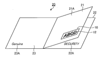
- FIG. 1 is an exploded perspective view schematically illustrating the identification medium according to the first embodiment.
- FIG. 2 is a plan view schematically showing the identification medium of the first embodiment.
- FIG. 3 is a cross-sectional view schematically showing a cross section in the X1-X1 direction of FIG.
- FIG. 4 is a cross-sectional view schematically showing a cross section in the Y1-Y1 direction of FIG.
- FIG. 5 is a perspective view schematically showing an article in a state where the second layer is disposed thereon.
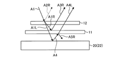
- FIG. 6 is an exploded cross-sectional view schematically showing a light path when light is irradiated from the second layer side of the identification medium.
- FIG. 7 is a perspective view schematically showing an article with a base material layer (first layer side) disposed thereon.
- FIG. 8 is a cross-sectional view schematically showing a state where the identification medium of FIG. 4 is turned upside down.
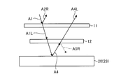
- FIG. 9 is an exploded sectional view schematically showing a light path when light is irradiated from the first layer side of the identification medium.
- FIG. 10 is an exploded perspective view schematically illustrating the identification medium according to the second embodiment.
- FIG. 11 is a plan view schematically showing the identification medium of Embodiment 2 from the second layer side.
- FIG. 12 is a plan view schematically showing the identification medium of the second embodiment from the third layer side.
- FIG. 13 is a cross-sectional view schematically showing a cross section in the X2-X2 direction of FIG.
- FIG. 14 is a cross-sectional view schematically showing a cross section in the Y2-Y2 direction of FIG.
- FIG. 15 is a perspective view schematically showing an article in a state where the second layer is disposed thereon.
- FIG. 16 is an exploded sectional view schematically showing a light path when light is irradiated from the second layer side of the identification medium.
- FIG. 17 is a perspective view schematically showing an article with a third layer disposed thereon.
- FIG. 18 is a cross-sectional view schematically showing a state where the identification medium of FIG. 14 is turned upside down.
- FIG. 19 is an exploded sectional view schematically showing a light path when light is irradiated from the third layer side of the identification medium.
- FIG. 20 is a graph showing the measurement results of the reflectance of the cholesteric resin layers A, B, and C manufactured in the example at a wavelength of 400 nm to 780 nm.
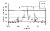
- FIG. 21 is a graph showing the measurement results of the reflectance of the cholesteric resin layers D and E manufactured in the example at a wavelength of 400 nm to 780 nm.
- FIG. 22 is a graph showing the measurement results of the reflectance of the cholesteric resin layers F and G manufactured in the example at wavelengths of 400 nm to 780 nm.
- FIG. 20 is a graph showing the measurement results of the reflectance of the cholesteric resin layers A, B, and C manufactured in the example at a wavelength of 400 nm to 780 nm.
- FIG. 21 is a graph showing the measurement results of the reflectance of the choleste
- FIG. 23 is a graph showing the measurement results of the reflectance of the cholesteric resin layers H and I manufactured in the example at a wavelength of 400 nm to 780 nm.
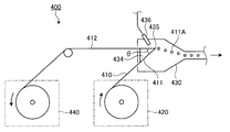
- FIG. 24 is a side view schematically illustrating an apparatus for manufacturing a peeled piece used to manufacture a peeled piece (flake) of a cholesteric resin layer in an example.
- a “pattern” refers to a planar shape unless otherwise specified. This pattern includes, for example, letters, numbers, figures, and the like.
- the “visible light region” indicates a wavelength range of 400 nm to 780 nm.
- the in-plane retardation of a film or layer indicates a value represented by (nx-ny) ⁇ d.
- the retardation in the thickness direction of the film or layer indicates a value represented by ⁇ (nx + ny) / 2-nz ⁇ ⁇ d.
- nx indicates the refractive index in the direction (in-plane direction) perpendicular to the thickness direction of the film or layer and in the direction giving the maximum refractive index.
- Ny indicates a refractive index in the in-plane direction of the film or layer and in a direction perpendicular to the nx direction.
- nz indicates the refractive index in the thickness direction of the film or layer.
- D indicates the thickness of the film or layer.
- (meth) acryl includes acryl, methacryl, and a combination thereof.
- (Meth) acrylate also includes acrylates, methacrylates, and combinations thereof.
- the term “(thio) epoxy” includes epoxy, thioepoxy, and combinations thereof.
- iso (thio) cyanate includes isocyanates, isothiocyanates and combinations thereof.
- FIG. 1 is an exploded perspective view schematically illustrating the identification medium according to the first embodiment of the present invention.
- FIG. 2 is a plan view schematically showing the identification medium of the first embodiment.
- FIG. 3 is a cross-sectional view schematically showing a cross section in the X1-X1 direction of FIG.
- FIG. 4 is a cross-sectional view schematically showing a cross section in the Y1-Y1 direction of FIG.
- FIG. 5 is a perspective view schematically showing an article in a state where the second layer is disposed thereon.
- FIG. 6 is an exploded cross-sectional view schematically showing a light path when light is irradiated from the second layer side of the identification medium.
- FIG. 7 is a perspective view schematically showing an article with a base material layer (first layer side) disposed thereon.
- FIG. 8 is a cross-sectional view schematically showing a state where the identification medium of FIG. 4 is turned upside down.
- FIG. 9 is an exploded sectional view schematically showing a light path when light is irradiated from the first layer side of the identification medium.
- the identification medium 10 of the present embodiment includes a first layer 11 and a second layer 12 provided so as to overlap the first layer 11. Further, in the identification medium 10 of the present embodiment, the reflectance of the first layer 11 and the reflectance of the second layer 12 have a predetermined relationship. In the identification medium 10 of the present embodiment, as shown in FIG. 3, an adhesive layer 15 and a base layer 14 are provided below the first layer 11. In the present application, a certain layer and another certain layer “overlap” means that when these two-dimensional positional relationships are observed from the thickness direction of the identification medium, at least a part of them is located at the same two-dimensional position. It means something.
- the first layer 11 is a layer that reflects one of right-handed circularly polarized light and left-handed circularly polarized light and transmits other circularly polarized light.
- the second layer 12 reflects at least a portion of the circularly polarized light in the same rotational direction as the circularly polarized light reflected by the first layer, and the circularly polarized light in the rotational direction opposite to the circularly polarized light reflected by the first layer. Is a layer that can transmit light.
- the second layer 12 is a portion of a character pattern called ABCD directly formed on the upper surface of the first layer 11.
- the second layer 12 is formed at a position where its entire area completely overlaps with the first layer 11. Since FIG.
- FIGS. 4 and 8 are schematic diagrams, the cross-sectional shape of the second layer 12 is shown as a schematic shape. More specifically, as the second layer 12, the planar shape of the character pattern and the schematic cross-sectional shape of a layer having a certain thickness are shown.
- the cross-sectional shape of the second layer 12 in FIGS. 4 and 8 and the cross-sectional shape of the second layer 112 and the third layer 113 in FIGS. 13, 14 and 18 are the same.
- ⁇ indicates the wavelength (nm)
- Rf 2 ( ⁇ ) indicates the reflectance of the second layer at the wavelength ⁇ .
- the S 2 value defined by the equation (1) is an integrated value of the reflectance Rf 2 of the second layer at a wavelength of 400 nm to 780 nm.
- ⁇ indicates a wavelength (nm)
- Rs ( ⁇ ) indicates a reflectance of the first layer at a wavelength ⁇ .
- the Ssf 2 value defined by the expression (2) is an integral value of the square root of the product of the reflectance Rs of the first layer and the reflectance Rf 2 of the second layer at a wavelength of 400 nm to 780 nm.
- Rs ( ⁇ ) and Rf 2 ( ⁇ ) are reflectances at a wavelength ( ⁇ ) when unpolarized light having a wavelength of 400 nm to 780 nm is incident on a target layer, and the reflectance is, for example, an ultraviolet-visible spectrophotometer. (UV-Vis 550, manufactured by JASCO Corporation). Since the measurement value measured by the above-mentioned device can include interface reflection, in such a case, the reflectances Rs ( ⁇ ) and Rf 2 ( ⁇ ) are calculated by subtracting the interface reflection component.
- the Ssf 2 / S 2 value is preferably at least 0.75, more preferably at least 1.0.
- the upper limit of the Ssf 2 / S 2 value is not particularly limited, but may be preferably 5 or less, more preferably 3 or less. With such a range, the character pattern of the second layer can be visually recognized well.
- the reflectance of the first layer with respect to non-polarized light incidence is preferably 35% or more and 50% or less at all wavelengths in the wavelength range of 420 nm to 650 nm.
- the reflectance is more preferably at least 40%, further preferably at least 45%.
- the first layer can be a broadband layer, whereby the reflection spectrum of the first layer and the second layer can be used.
- the reflectance of the first layer for non-polarized light incidence may include interfacial reflections.
- the identification medium of the present embodiment is preferably transparent or translucent. It is preferable that the identification medium 10 be transparent or translucent, because duplication or forgery of the identification medium can be made difficult.
- the transparency of the identification medium may be such that the identification medium is placed on an article on which characters, pictures, and the like are printed, and the letters and the like printed on the article can be visually recognized through the identification medium.
- the transmittance of non-polarized light incident on the identification medium can be preferably 20% or more, more preferably 40% or more.
- the upper limit of the transmittance is not limited, but may be, for example, 90%.
- the first layer 11 is a layer that reflects one of right-handed circularly polarized light and left-handed circularly polarized light and transmits other circularly polarized light.
- a layer of a resin having cholesteric regularity (hereinafter, also referred to as “cholesteric resin layer”) can be used.
- the cholesteric regularity of the resin layer having cholesteric regularity means that the molecular axes are arranged in a certain direction on one plane, but the directions of the molecular axes are shifted at a slight angle in the next plane overlapping with the cholesteric regularity.
- the structure is such that the angle of the molecular axis in the plane is shifted (twisted) as the light passes through the overlappingly arranged planes sequentially, so that the angle is further shifted in the next plane. That is, when the molecules in the layer have cholesteric regularity, the molecules are arranged in a layer of a large number of molecules in the resin layer. In one layer A of such a large number of molecular layers, the molecules are aligned so that the axes of the molecules are in a certain direction, and in the adjacent layer B, the molecules are shifted at an angle from the direction in the layer A.
- the molecules are aligned in the direction, and in layer C, which is further adjacent thereto, the molecules are aligned in a direction further deviating at an angle to the direction in layer B.
- a structure in which the angles of the molecules are continuously shifted and the molecules are twisted is formed.
- Such a structure in which the direction of the molecular axis is twisted becomes an optically chiral structure.
- the cholesteric resin layer usually has a circularly polarized light separating function. That is, the cholesteric resin layer has a property of transmitting one of the right circularly polarized light and the left circularly polarized light and reflecting a part or all of the other circularly polarized light. The reflection in the cholesteric resin layer reflects circularly polarized light while maintaining its chirality.
- the wavelength at which the circularly polarized light separating function is exhibited depends on the pitch of the helical structure in the cholesteric resin layer.
- the pitch of the helical structure is the distance in the direction of the normal to the plane until the direction of the molecular axis in the helical structure gradually deviates as it travels along the plane and then returns to the original molecular axis direction.
- the cholesteric resin layer can be obtained, for example, by providing a film of the cholesteric liquid crystal composition on a suitable support for forming the resin layer, and curing the film of the cholesteric liquid crystal composition.
- the obtained layer can be used as it is as a cholesteric resin layer.
- This cholesteric resin layer is a layer made of a film of a material itself that reflects one of right-handed circularly polarized light and left-handed circularly polarized light and transmits other circularly polarized light. Therefore, the cholesteric resin layer itself can be used as the first layer.
- the cholesteric liquid crystal composition for forming the cholesteric resin layer for example, a composition containing a liquid crystal compound and capable of exhibiting a cholesteric liquid crystal phase when a film is formed on a support can be used.
- the liquid crystal compound a liquid crystal compound which is a polymer compound and a polymerizable liquid crystal compound can be used.
- a polymerizable liquid crystalline compound By polymerizing such a polymerizable liquid crystalline compound in a state of exhibiting cholesteric regularity, a film of the cholesteric liquid crystal composition is cured, and a non-liquid crystalline resin layer cured while exhibiting cholesteric regularity can be obtained. it can.
- Suitable cholesteric resin layers having a high reflectance in the wavelength region of 420 nm to 650 nm include, for example, (i) a cholesteric resin layer in which the helical structure pitch is gradually changed, and (ii) a helical structure pitch.
- the cholesteric resin layer in which the pitch of the helical structure is changed stepwise can be obtained by forming a plurality of cholesteric resin layers having different helical structure pitches.
- a cholesteric resin layer can be manufactured by preparing a plurality of cholesteric resin layers having different spiral structure pitches in advance, and then fixing each layer via an adhesive or an adhesive.
- it can be manufactured by forming a certain cholesteric resin layer and then sequentially forming another cholesteric resin layer.
- the cholesteric resin layer in which the pitch of the helical structure is continuously changed is not particularly limited by its manufacturing method.
- a cholesteric resin layer manufacturing method a cholesteric resin layer is formed.
- a cholesteric liquid crystal composition containing a polymerizable liquid crystal compound is preferably applied onto another layer such as an alignment film to obtain a liquid crystal composition layer, and then subjected to one or more light irradiation and / or A method in which the layer is cured in a state where the pitch of the helical structure is continuously changed by a heat treatment.
- Such an operation is an operation for expanding the reflection band of the cholesteric resin layer, and is therefore called broadband processing.
- the band is preferable because a wide reflection band can be realized even with a cholesteric resin layer having a small thickness of, for example, 5 ⁇ m or less.
- a cholesteric liquid crystal composition (X) described in detail below can be mentioned.
- the cholesteric resin layer in which the pitch of the helical structure is continuously changed may be used alone or as a plurality of layers.
- a cholesteric resin layer exhibiting a circularly polarized light separating function in a part of the visible light region and a cholesteric resin layer exhibiting a circularly polarized light separating function in another region are combined, and a wide range of the visible light region is provided.
- the cholesteric resin layer may be a resin layer composed of only one layer or a resin layer composed of two or more layers.
- the cholesteric resin layer may have two or more cholesteric resin layers of the above (i), or may have two or more cholesteric resin layers of the above (ii), Both of these may be combined to provide two or more layers.
- the number of layers constituting the cholesteric resin layer is preferably from 1 to 100 layers, more preferably from 1 to 20 layers, from the viewpoint of ease of production.
- a discrimination medium in a preferred embodiment can be obtained only by using only one layer.
- the cholesteric liquid crystal composition (X) contains a compound represented by the following formula (5) and a specific rod-like liquid crystal compound. Further, as the compound represented by the formula (5) and the rod-shaped liquid crystalline compound, one kind may be used alone, and two kinds or more may be used in combination at an arbitrary ratio. Hereinafter, these components will be sequentially described.
- R 1 -A 1 -BA 2 -R 2 each independently represent a linear or branched alkyl group having 1 to 20 carbon atoms, or a linear alkyl group having 1 to 20 carbon atoms. Or a group selected from the group consisting of a branched alkylene oxide group, a hydrogen atom, a halogen atom, a hydroxyl group, a carboxyl group, a (meth) acrylic group, an epoxy group, a mercapto group, an isocyanate group, an amino group, and a cyano group. It is.
- the alkyl group and the alkylene oxide group may be unsubstituted or substituted by one or more halogen atoms.
- the halogen atom, hydroxyl group, carboxyl group, (meth) acryl group, epoxy group, mercapto group, isocyanate group, amino group, and cyano group are an alkyl group having 1 to 2 carbon atoms, and an alkylene oxide group. May be combined with.
- R 1 and R 2 include a halogen atom, a hydroxyl group, a carboxyl group, a (meth) acryl group, an epoxy group, a mercapto group, an isocyanate group, an amino group, and a cyano group.
- At least one of R 1 and R 2 is preferably a reactive group.
- the compound represented by the formula (5) is fixed in the cholesteric resin layer at the time of curing, so that a stronger layer can be formed.
- the reactive group include a carboxyl group, a (meth) acryl group, an epoxy group, a mercapto group, an isocyanate group, and an amino group.
- a 1 and A 2 are each independently 1,4-phenylene, 1,4-cyclohexylene, 1,4-cyclohexenyl, 4,4′-biphenylene, 4,4 Represents a group selected from the group consisting of a '-bicyclohexylene group and a 2,6-naphthylene group.
- the 1,4-phenylene group, 1,4-cyclohexylene group, 1,4-cyclohexenyl group, 4,4′-biphenylene group, 4,4′-bicyclohexylene group, and 2,6-naphthylene group Unsubstituted or substituted by at least one substituent such as a halogen atom, a hydroxyl group, a carboxyl group, a cyano group, an amino group, an alkyl group having 1 to 10 carbon atoms, or a halogenated alkyl group. May be. When two or more substituents are present in each of A 1 and A 2 , they may be the same or different.
- a 1 and A 2 include a group selected from the group consisting of a 1,4-phenylene group, a 4,4′-biphenylene group, and a 2,6-naphthylene group.
- aromatic ring skeletons are relatively rigid as compared with the alicyclic skeletons, have high affinity for the mesogen of the rod-like liquid crystalline compound, and have higher alignment uniformity.
- At least one of the compounds of the formula (5) preferably has liquid crystallinity, and preferably has chirality.
- the cholesteric liquid crystal composition (X) preferably contains a mixture of a plurality of optical isomers as the compound of the formula (5). For example, it may contain a mixture of multiple enantiomers and / or diastereomers.
- at least one of the compounds of the formula (5) has a melting point in the range of 50 ° C to 150 ° C.
- ⁇ n is preferably high.
- ⁇ n as the cholesteric liquid crystal composition (X) can be improved, and a cholesteric resin layer having a wide wavelength range capable of reflecting circularly polarized light is produced. can do.
- At least one ⁇ n of the compound of the formula (5) is preferably at least 0.18, more preferably at least 0.22.
- the upper limit of ⁇ n may be, for example, 0.50.
- the cholesteric liquid crystal composition (X) usually contains a rod-shaped liquid crystalline compound having ⁇ n of 0.18 or more and having at least two or more reactive groups in one molecule.
- Examples of the rod-like liquid crystalline compound include a compound represented by the formula (6). R 3 -C 3 -D 3 -C 5 -MC 6 -D 4 -C 4 -R 4 (6)
- R 3 and R 4 are reactive groups and each independently represents a (meth) acryl group, a (thio) epoxy group, an oxetane group, a thietanyl group, an aziridinyl group, a pyrrole group, or a vinyl group.
- the film strength that can be practically used is a pencil hardness (JIS K5400), which is usually HB or more, preferably H or more. By increasing the film strength in this manner, scratches can be made less likely to occur, and handling properties can be improved.
- D 3 and D 4 represent a single bond, a linear or branched alkyl group having 1 to 20 carbon atoms, and a linear or branched alkyl group having 1 to 20 carbon atoms.
- M represents a mesogen group. Specifically, M represents an azomethine, an azoxy, a phenyl, a biphenyl, a terphenyl, a naphthalene, an anthracene, an benzoate, and a cyclohexane carboxy which may be unsubstituted or have a substituent.
- R 5 and R 7 represent a hydrogen atom or an alkyl group having 1 to 10 carbon atoms.
- R 6 represents a hydrogen atom or an alkyl group having 1 to 6 carbon atoms.
- Examples of the substituent in the aforementioned “alkyl group having 1 to 10 carbon atoms which may have a substituent” include a halogen atom, a hydroxyl group, a carboxyl group, a cyano group, an amino group, and a carbon atom having 1 to 6 carbon atoms.
- Examples include a carbonyloxy group and an alkoxycarbonyloxy group having 2 to 7 carbon atoms.
- the rod-like liquid crystalline compound preferably has an asymmetric structure.
- the asymmetric structure means a structure in which R 3 -C 3 -D 3 -C 5 -and -C 6 -D 4 -C 4 -R 4 are different from each other with respect to the mesogen group M in formula (6).
- alignment uniformity can be further improved.
- ⁇ ⁇ n of the rod-shaped liquid crystalline compound is preferably 0.18 or more, more preferably 0.22 or more.
- the absorption edge on the long wavelength side of the ultraviolet absorption spectrum may reach the visible range.
- rod-like liquid crystalline compounds whose absorption edge extends to the visible region can also be used as long as they do not adversely affect the desired optical performance of the spectrum.
- a rod-like liquid crystalline compound having such a high ⁇ n a cholesteric resin layer having high optical performance (for example, selective reflection performance of circularly polarized light) can be obtained.
- the upper limit of ⁇ n may be, for example, 0.50.
- rod-shaped liquid crystalline compound examples include the following compounds (B1) to (B10).
- the rod-shaped liquid crystalline compound is not limited to the following compounds.
- the weight ratio of (total weight of compounds of formula (5)) / (total weight of rod-like liquid crystal compounds) is preferably 0.05 or more, more preferably 0.1 or more, It is particularly preferably at least 0.15, preferably at most 1, more preferably at most 0.65, particularly preferably at most 0.45.
- the uniformity of alignment can be improved.
- the content is not more than the upper limit, the alignment uniformity can be increased, the stability of the liquid crystal phase can be increased, and further, ⁇ n as the liquid crystal composition can be increased to obtain desired optical performance (for example, select circularly polarized light). Stable reflection characteristic).
- the total weight indicates the weight when one type is used, and indicates the total weight when two or more types are used.
- the compound of formula (5) preferably has a molecular weight of less than 600, and the rod-shaped liquid crystalline compound preferably has a molecular weight of 600 or more. Thereby, the compound of the formula (5) can enter the gaps between the rod-shaped liquid crystalline compounds having a higher molecular weight, and the alignment uniformity can be improved.
- the cholesteric liquid crystal composition such as the cholesteric liquid crystal composition (X) may optionally contain a crosslinking agent in order to improve the strength and durability of the cured film.
- a cross-linking agent the cholesteric liquid crystal composition reacts at the same time as the film is cured, or performs a heat treatment after the curing to accelerate the reaction, or the reaction proceeds naturally due to moisture to increase the cross-linking density of the cholesteric resin layer. And those which do not deteriorate the uniformity of alignment can be appropriately selected and used. Therefore, for example, any crosslinking agent that is cured by ultraviolet light, heat, moisture, or the like can be suitably used.
- crosslinking agent examples include trimethylolpropane tri (meth) acrylate, pentaerythritol tri (meth) acrylate, pentaerythritol tetra (meth) acrylate, dipentaerythritol hexa (meth) acrylate, and 2- (2-vinyloxyethoxy).
- Polyfunctional acrylate compounds such as ethyl acrylate; epoxy compounds such as glycidyl (meth) acrylate, ethylene glycol diglycidyl ether, glycerin triglycidyl ether, and pentaerythritol tetraglycidyl ether; 2,2-bishydroxymethylbutanol-tris [3- ( 1-aziridinyl) propionate], 4,4-bis (ethyleneiminocarbonylamino) diphenylmethane, trimethylolpropane-tri- ⁇ -aziridinylpropionate Aziridine compounds such as ononates; hexamethylene diisocyanate, isocyanurate compounds derived from hexamethylene diisocyanate, isocyanurate compounds such as biuret isocyanates, and adduct isocyanates; polyoxazoline compounds having an oxazoline group in a side chain; vinyltrimethoxysilane; N-
- one kind of the crosslinking agent may be used alone, or two or more kinds may be used in combination at an arbitrary ratio.
- a known catalyst may be used depending on the reactivity of the crosslinking agent. By using a catalyst, productivity can be improved in addition to improvement in the film strength and durability of the cholesteric resin layer.
- the amount of the crosslinking agent is preferably such that the amount of the crosslinking agent in the cured film obtained by curing the film of the cholesteric liquid crystal composition is 0.1% by weight to 15% by weight.
- the cholesteric liquid crystal composition may optionally contain a photoinitiator.
- a photoinitiator for example, a known compound that generates a radical or an acid by ultraviolet light or visible light can be used.
- Specific examples of the photoinitiator include benzoin, benzyl methyl ketal, benzophenone, biacetyl, acetophenone, Michler's ketone, benzyl, benzyl isobutyl ether, tetramethylthiuram mono (di) sulfide, 2,2-azobisisobutyronitrile, , 2-azobis-2,4-dimethylvaleronitrile, benzoyl peroxide, di-tert-butyl peroxide, 1-hydroxycyclohexylphenyl ketone, 2-hydroxy-2-methyl-1-phenyl-propan-1-one, 1- (4-isopropylphenyl) -2-hydroxy-2-methylpropan-1-one, thioxan
- One of these may be used alone, or two or more thereof may be used in combination at an arbitrary ratio. Further, if necessary, the curability may be controlled using a known photosensitizer or a tertiary amine compound as a polymerization accelerator.
- the amount of the photoinitiator is preferably 0.03% by weight to 7% by weight in the cholesteric liquid crystal composition.
- the cholesteric liquid crystal composition may optionally contain a surfactant.
- a surfactant for example, a surfactant that does not inhibit the orientation can be appropriately selected and used.
- a surfactant for example, a nonionic surfactant containing a siloxane or a fluorinated alkyl group in a hydrophobic group portion is preferably exemplified. Among them, oligomers having two or more hydrophobic groups in one molecule are particularly preferable.
- surfactants include PF-151N, PF-636, PF-6320, PF-656, PF-6520, PF-3320, PF-651, and PF-652 of PolyFox manufactured by OMNOVA; FTX-209F, FTX-208G, FTX-204D; Surflon KH-40 of Seimi Chemical Co .;
- one type of surfactant may be used alone, or two or more types may be used in combination at an arbitrary ratio.
- the amount of the surfactant is preferably such that the amount of the surfactant in the cured film obtained by curing the cholesteric liquid crystal composition is 0.05% by weight to 3% by weight.
- the amount of the surfactant is equal to or more than the lower limit of the above range, the alignment regulating force at the air interface can be increased, so that alignment defects can be prevented.
- the amount is not more than the upper limit value, it is possible to prevent a decrease in alignment uniformity due to an excessive surfactant entering between liquid crystal molecules.
- the cholesteric liquid crystal composition may optionally contain a chiral agent.
- the twist direction of the cholesteric resin layer can be appropriately selected depending on the type and structure of the chiral agent used. When the twist is to the right, a chiral agent that imparts dextrorotation is used, and when the twist direction is to the left, it can be realized by using a chiral agent that imparts levorotation.
- Specific examples of the chiral agent include JP-A-2005-28981, JP-A-2004-115414, JP-A-2003-66214, JP-A-2003-313187, JP-A-2003-342219, and JP-A-2003-342219.
- JP-A-2000-290315, JP-A-6-07962, US Pat. No. 6,468,444, WO 98/00428, JP-A-2007-176870, and the like can be appropriately used.
- available as LC756 from BASF Palio Color available as LC756 from BASF Palio Color.
- One type of chiral agent may be used alone, or two or more types may be used in combination at an arbitrary ratio.
- the amount of the chiral agent can be arbitrarily set within a range that does not lower the desired optical performance.
- the specific amount of the chiral agent is usually 1% by weight to 60% by weight in the cholesteric liquid crystal composition.
- the cholesteric liquid crystal composition may further contain other optional components as necessary.
- the optional component include a solvent, a polymerization inhibitor for improving pot life, an antioxidant for improving durability, an ultraviolet absorber, and a light stabilizer.
- One of these optional components may be used alone, or two or more of them may be used in combination at an arbitrary ratio.
- the amounts of these optional components can be arbitrarily set within a range that does not lower the desired optical performance.
- the method for producing the cholesteric liquid crystal composition is not particularly limited, and the cholesteric liquid crystal composition can be produced by mixing the above components.
- the cholesteric resin layer is, for example, subjected to a treatment such as a corona discharge treatment and a rubbing treatment on the surface of a support made of a film of a transparent resin or the like, if necessary, and further provided with an alignment film if necessary. It can be obtained by providing a film of the cholesteric liquid crystal composition thereon and further performing an alignment treatment and / or a curing treatment as necessary.
- Examples of the support that can be used for forming the cholesteric resin layer include, for example, alicyclic olefin polymers, chain olefin polymers such as polyethylene and polypropylene, triacetyl cellulose, polyvinyl alcohol, polyimide, polyarylate, polyesters such as polyethylene terephthalate, and polycarbonate. And a single-layer or multilayer film made of synthetic resin such as polysulfone, polyether sulfone, modified acrylic polymer, epoxy resin, polystyrene, and acrylic resin.
- Alignment film for example, on the surface of the support, after applying a corona discharge treatment or the like as necessary, by applying a solution obtained by dissolving the material of the alignment film in a solvent, dried, and then subjected to rubbing treatment Can be formed.
- a corona discharge treatment or the like for example, cellulose, silane coupling agent, polyimide, polyamide, polyvinyl alcohol, epoxy acrylate, silanol oligomer, polyacrylonitrile, phenol resin, polyoxazole, cyclized polyisoprene, and the like can be used.
- the application of the cholesteric liquid crystal composition on the support or the alignment film can be performed by a known method, for example, an extrusion coating method, a direct gravure coating method, a reverse gravure coating method, a die coating method, a bar coating method, or the like. .
- the alignment treatment can be performed, for example, by heating the cholesteric liquid crystal composition film at 50 ° C. to 150 ° C. for 0.5 minutes to 10 minutes.
- the orientation treatment By performing the orientation treatment, the cholesteric liquid crystal composition in the film can be favorably oriented.
- the curing treatment can be performed by one or more combinations of light irradiation and heating treatment.
- the heating conditions are, for example, usually at least 40 ° C., preferably at least 50 ° C., and usually at most 200 ° C., preferably at most 140 ° C., usually at least 1 second, preferably at least 5 seconds, and usually at least 3 minutes.
- the time may be 120 seconds or less.
- the light used for light irradiation includes not only visible light but also ultraviolet light and other electromagnetic waves.
- Light irradiation can be performed, for example, by irradiating light having a wavelength of 200 nm to 500 nm for 0.01 seconds to 3 minutes.
- a wide circularly polarized light separating function can be obtained.
- a relatively strong ultraviolet such 50mJ / cm 2 ⁇ 10,000mJ / cm 2
- a cholesteric resin layer can be obtained.
- the above-described expansion of the reflection band and irradiation with strong ultraviolet light may be performed in air, or some or all of the steps may be performed in an atmosphere in which the oxygen concentration is controlled (for example, under a nitrogen atmosphere). .
- the step of applying and curing the cholesteric liquid crystal composition on another layer such as an alignment film is not limited to one time, and the application and curing may be repeated plural times to form two or more cholesteric resin layers.
- a cholesteric liquid crystal composition such as the cholesteric liquid crystal composition (X)
- X cholesteric liquid crystal composition
- a well-aligned rod-like liquid crystal compound having ⁇ n of 0.18 or more is obtained.
- a cholesteric resin layer having a thickness of 5 ⁇ m or more can be easily formed.
- the cholesteric resin layer thus obtained can be used as a first layer together with the support and the alignment film. If necessary, the support or the like may be peeled off, and only the cholesteric resin layer may be transferred and used as the first layer.
- the thickness of the first layer is preferably 2 ⁇ m or more, more preferably 3 ⁇ m or more, preferably 1000 ⁇ m or less, more preferably 500 ⁇ m or less.
- the thickness of the first layer refers to the sum of the thicknesses of the respective layers when the first layer is a layer of two or more layers, and the thickness when the first layer is a single layer. Point.
- the in-plane retardation of the support is preferably 20 nm or less, more preferably 10 nm or less, and ideally 0 nm.
- the second layer is a layer provided so as to directly (that is, in contact with) the first layer or indirectly (that is, to be separated by interposing another layer or the like).
- the second layer 12 is a layer provided so as to directly overlap the first layer.
- the second layer reflects at least a portion of the circularly polarized light in the same rotational direction as the circularly polarized light reflected by the first layer, and transmits the circularly polarized light in the opposite rotational direction to the circularly polarized light reflected by the first layer.
- It is a layer that can be formed. That is, the second layer 12 is a layer that does not reflect or hardly reflects circularly polarized light in the rotation direction opposite to the circularly polarized light reflected by the first layer.
- the second layer 12 is preferably a layer containing flakes of a resin having cholesteric regularity (also referred to as “cholesteric resin”).
- the cholesteric resin layer suitable as the first layer 11 can reflect one of right-handed circularly polarized light and left-handed circularly polarized light and transmit other circularly polarized light in at least a part of the visible light region even when a crushed material is used. Therefore, it is preferable to use the crushed material as flakes of the second layer 12.
- Cholesteric resin which is the material of the flakes, has as high a reflectance as possible from the viewpoint that the identification of authenticity is clear and the degree of freedom of design is high, and as a result, the reflectance in the wavelength range to be reflected is low. Tall ones are preferred.
- Cholesteric resin flakes can be produced, for example, by the method for producing a strip as described in Japanese Patent No. 6142714.
- ⁇ ⁇ ⁇ ⁇ Along with cholesteric resin flakes, it is possible to use flakes of a material having no polarization characteristics.
- the flakes having no polarization property include, for example, at least one kind selected from carbon black, oxides, nitrides, and nitrides of metals belonging to Groups 3 to 11 of the fourth period of the periodic table. Flakes. One of these may be used alone, or two or more may be used in combination at an arbitrary ratio.
- the particle size of the flakes 12F contained in the second layer 12 is preferably at least 1 ⁇ m in order to obtain decorativeness, and more preferably at least the film thickness of the second layer 12 (in this case,
- the particle size of a flake refers to the diameter of a circle having the same area as the flake, that is, observing a planar image of the flake, calculating the diameter of the circle having the same area as the image, and calculating the diameter of the flake. Particle size).
- the flakes can effectively receive the light incident on the second layer, so that the circularly polarized light separating function of the second layer can be enhanced.
- the particle size of the flake is preferably 500 ⁇ m or less, more preferably 100 ⁇ m or less.
- the second layer 12 is, for example, a flake 12F made of a pulverized cholesteric resin layer, a solvent, and a binder, and, if necessary, applying an ink containing an optional component on a support, followed by drying. Can be produced.
- an inorganic solvent such as water
- an organic solvent is used.
- organic solvents such as ketones, alkyl halides, amides, sulfoxides, heterocyclic compounds, hydrocarbons, esters, and ethers. Among these, ketones are preferable in consideration of the load on the environment.
- one type of solvent may be used alone, or two or more types may be used in combination at an arbitrary ratio.
- the amount of the solvent is usually at least 40 parts by weight, preferably at least 60 parts by weight, more preferably at least 80 parts by weight, and usually at most 1,000 parts by weight, preferably at most 800 parts by weight, based on 100 parts by weight of the pulverized product of the cholesteric resin layer. It is at most 600 parts by weight, more preferably at most 600 parts by weight.
- a polymer is usually used as the binder.
- the polymer include a polyester polymer, an acrylic polymer, a polystyrene polymer, a polyamide polymer, a polyurethane polymer, a polyolefin polymer, a polycarbonate polymer, and a polyvinyl polymer.
- One type of binder may be used alone, or two or more types may be used in combination at an arbitrary ratio.
- the amount of the binder is usually 20 parts by weight or more, preferably 40 parts by weight or more, more preferably 60 parts by weight or more, and usually 1000 parts by weight or less, preferably 800 parts by weight, based on 100 parts by weight of the pulverized product of the cholesteric resin layer. It is at most 600 parts by weight, more preferably at most 600 parts by weight.
- Optional components that the ink can contain include, for example, antioxidants, ultraviolet absorbers, light stabilizers, bluing agents and the like. One of these may be used alone, or two or more thereof may be used in combination at an arbitrary ratio.
- the first layer 11 is printed with the above-described ink in the form of a character pattern, and dried to form the second layer 12 as a layer containing flakes 12F made of pulverized cholesteric resin layers. can get.
- the ink may contain a monomer of the polymer instead of or in combination with the polymer as a binder.
- a second layer containing flakes and a binder, each of which is a crushed cholesteric resin layer can be produced.
- the ink when the ink contains a monomer, the ink preferably contains a polymerization initiator.
- An adhesive layer 15 is provided on a lower surface of the first layer 11 shown in FIG.
- the adhesive layer 15 is a layer that joins the first layer 11 and the base material layer 14.
- the adhesive layer is an optional layer.
- a layer of a pressure-sensitive adhesive composition containing a polymer exhibiting tackiness (hereinafter, may be simply referred to as a "main polymer") may be used.
- the pressure-sensitive adhesive composition described in Japanese Patent No. 6067667 can be used.
- the thickness of the adhesive layer 15 is preferably 5 ⁇ m or more, more preferably 10 ⁇ m or more, preferably 100 ⁇ m or less, more preferably 50 ⁇ m or less.
- the visible light transmittance of the adhesive layer 15 at a wavelength of 450 nm to 650 nm is preferably 80% or more, more preferably 85% or more.
- the base material layer 14 is a layer adhered to the first layer 11 via the adhesive layer 15.
- Examples of the base material layer 14 include plastic films and sheets such as a vinyl chloride sheet and an acrylic resin sheet.
- the thickness of the base material layer 14 is preferably 50 ⁇ m or more, more preferably 100 ⁇ m or more, preferably 2000 ⁇ m or less, more preferably 1000 ⁇ m or less.
- the visible light transmittance of the base material layer 14 is preferably 80% or more, more preferably 85% or more. From the viewpoint that the circular polarization state of the first layer 11 is maintained, the in-plane retardation of the base layer 14 is preferably 20 nm or less, more preferably 10 nm or less, and ideally 0.
- Examples of articles provided with the identification medium 10 include booklets such as passports, tags for articles such as clothing, and packaging for articles such as pharmaceuticals and cosmetics.
- the method for determining the authenticity of the identification medium 10 includes the steps of: observing, from the second layer 12 side, reflected light of light emitted from the second layer 12 side of the identification medium 10; A first step of determining whether or not the information according to 12 is visible, and a reflected light of light irradiated from the side opposite to the second layer side of the identification medium 10 is observed from the side opposite to the second layer side. And determining whether or not the information by the second layer 12 is visible.
- the “opposite side of the second layer side” in the identification medium 10 is the first layer 11 side.
- the “second layer side” of the identification medium may be used.
- the “opposite side” is the layer X side of the identification medium.
- the first layer 11 reflects right circularly polarized light (corresponding to one of right circularly polarized light and left circularly polarized light) and transmits other circularly polarized light
- the second layer 12 reflects at least a part of right circularly polarized light (circular polarized light in the same rotation direction as the circularly polarized light reflected by the first layer) and transmits left circularly polarized light (left circularly polarized light). Is not reflected).
- the identification medium 10 of the present embodiment is used as a part of a booklet 20 (article) such as a passport.
- the identification medium 10 is provided on a part of the leaf 21 of the n-th booklet.
- the identification medium 10 is arranged on the side where the second layer 12 faces the “n ⁇ 1” -th leaf 23 of the booklet, and the base material layer 14 is on the side where the “n + 1” -th leaf 22 of the booklet faces It is arranged so that it becomes.
- the surface 21A on the second layer 12 side of the n-th leaf 21 of the booklet is a surface that is overlapped with the “n ⁇ 1” -th leaf 23 of the booklet, and n
- the surface 21B on the base material layer 14 side of the leaf 21 is a surface that is overlapped with the “n + 1” leaf 22 of the booklet.
- character information “Genuine” is printed on a portion 23A on which the identification medium 10 is overlapped.
- character information “SECURITY” is printed on a portion 22A on which the identification medium 10 is overlapped.
- the identification medium 10 is superimposed on the “n + 1” -th leaf 22 of the booklet so that the second layer 12 faces upward, and the identification medium 10 It is determined whether or not the information by the second layer 12 can be visually recognized when observing 10.
- the identification medium 10 is superimposed on the “n ⁇ 1” -th leaf 23 of the booklet so that the first layer 11 is on top, and the identification medium 10 is placed on the first layer 11 side. It is determined whether or not the information by the second layer 12 can be visually recognized.
- the article (booklet) including the identification medium 10 is genuine. It can be determined that there is.
- a step of checking the transparency (transparent, translucent, or opaque) of the identification medium 10 can be performed.
- the step of checking the transparency can be performed as follows. Information such as characters and patterns is printed in advance on the base on which the identification medium 10 is superimposed (in this embodiment, the “n + 1” -th leaf 22 and the “n ⁇ 1” -th leaf 23). By observing the information printed on the base through 10, and if the information is visible, it can be confirmed that the identification medium 10 is transparent or translucent.
- the character information “SECURITY” of the “n + 1” -th leaf 22 of the booklet and the character information “Genuine” of the “n ⁇ 1” -th leaf 23 of the booklet can be visually recognized. For example, it can be confirmed that the identification medium 10 is transparent or translucent.
- the identification medium 10 is overlaid on the base 22 (the “n + 1” -th leaf 22 of the booklet) so that the second layer 12 is on the upper side.
- the base 22 the “n + 1” -th leaf 22 of the booklet
- the second layer 12 is a layer that reflects at least a part of right circularly polarized light and does not reflect or hardly reflects left circularly polarized light. Therefore, as shown in FIG. 6, of the non-polarized light A1 such as natural light, a part of the right circularly polarized light is reflected by the second layer 12 and is visually recognized as the backscattered light A2R. Information is visible. Of the non-polarized light A1, a part of the left circularly polarized light A1L and a part of the right circularly polarized light A1R pass through the second layer 12.
- the right circularly polarized light A1R transmitted through the second layer 12 is reflected by the first layer 11 as right circularly polarized light A3R, and the left circularly polarized light A1L transmitted through the second layer 12 transmits through the first layer 11.
- the left circularly polarized light A1L transmitted through the first layer 11 is reflected by the base 22 as non-polarized light A4.
- a part of the unpolarized light A4 is reflected by the first layer 11 as right circularly polarized light A5R.
- the left circularly polarized light A4 of the non-polarized light A4 reflected by the base 22 is transmitted through the first layer 11 and the second layer in order, and is emitted to the outside of the identification medium 10.
- the identification medium 10 is overlaid on the base 23 (the “n ⁇ 1” -th leaf of the booklet) so that the first layer 11 is on A case where observation is performed with the naked eye from one layer 11 side will be described.
- the first layer 11 is a layer that reflects right circularly polarized light and transmits left circularly polarized light. Therefore, as shown in FIG. 9, of the non-polarized light A1 such as natural light, right circularly polarized light is reflected by the first layer 11 as regular reflection light A2R, and left circularly polarized light A1L is transmitted through the first layer 11.
- the left-handed circularly polarized light A1L transmitted through the first layer 11 is transmitted through the second layer 12 and reflected on the base 23 as non-polarized light A4.
- the right circularly polarized light of the non-polarized light A4 is reflected as backscattered light A5R in the second layer 12, but the reflected light travels in the direction of the base 23, so that the information of the second layer 12 can be visually recognized from above. Can not.
- the left circularly polarized light of the non-polarized light A4 sequentially passes through the second layer 12 and the first layer 11 and is emitted to the outside of the identification medium 10.
- the information of the second layer 12 can be visually recognized when observed from the second layer 12 side, and the information can be visually recognized when observed from the first layer 11 side. Since the information of the second layer 12 cannot be visually recognized, the article including the identification medium 10 can be determined to be genuine.
- the authenticity can be determined without using a special viewer. Therefore, according to the present embodiment, it is possible to provide an identification medium capable of determining authenticity without using a special viewer, a method of determining the authenticity of the identification medium, and an article including the identification medium.
- FIG. 10 is an exploded perspective view schematically illustrating the identification medium according to the second embodiment.
- FIG. 11 is a plan view schematically showing the identification medium of Embodiment 2 from the second layer side.
- FIG. 12 is a plan view schematically showing the identification medium of the second embodiment from the third layer side.
- FIG. 13 is a cross-sectional view schematically showing a cross section in the X2-X2 direction of FIG.
- FIG. 14 is a cross-sectional view schematically showing a cross section in the Y2-Y2 direction of FIG.
- FIG. 15 is a perspective view schematically showing an article in a state where the second layer is disposed thereon.
- FIG. 11 is a plan view schematically showing the identification medium of Embodiment 2 from the second layer side.
- FIG. 12 is a plan view schematically showing the identification medium of the second embodiment from the third layer side.
- FIG. 13 is a cross-sectional view schematically showing a cross section in the X2-X2 direction of FIG.
- FIG. 16 is an exploded sectional view schematically showing a light path when light is irradiated from the second layer side of the identification medium.
- FIG. 17 is a perspective view schematically showing an article with a third layer disposed thereon.
- FIG. 18 is a cross-sectional view schematically showing a state where the identification medium of FIG. 14 is turned upside down.
- FIG. 19 is an exploded sectional view schematically showing a light path when light is irradiated from the third layer side of the identification medium.
- the identification medium 100 of the present embodiment is implemented in that the first layer includes, on the surface opposite to the surface on which the second layer is provided, a third layer provided so as to overlap the first layer. This is different from the first embodiment.
- the identification medium 100 of the present embodiment is an embodiment in which a third layer is provided on the base material layer of the identification medium 10 of the first embodiment. That is, the first layer 111, the second layer 112, the adhesive layer 115, and the base material layer 114 of the identification medium 100 of the present embodiment are respectively the first layer 11 and the second layer 11 of the identification medium 10 of the first embodiment. It corresponds to the layer 12, the adhesive layer 15, and the base material layer 14. In the following description, differences from the first embodiment will be mainly described.
- the identification medium 100 of the present embodiment includes a first layer 111 and a second layer 112 provided so as to overlap the first layer 111. Also, as shown in FIG. 13, the identification medium 100 has an adhesive layer 115, a base material layer 114, and an adhesive layer 115 on the lower surface of the first layer 111 (the surface opposite to the surface on which the second layer 112 is provided). A third layer 113 is provided. Hereinafter, the third layer 113 will be described.
- the third layer 113 is a layer provided (indirectly) on the lower surface of the first layer 111 via the adhesive layer 115 and the base material layer 114.
- the third layer may be provided so as to directly overlap the surface of the first layer opposite to the surface on which the second layer is provided.
- the third layer 113 is a layer capable of transmitting circularly polarized light in the rotation direction opposite to the circularly polarized light reflected by the first layer, that is, a layer that does not reflect or hardly reflects the circularly polarized light.
- the third layer 113 is a portion of a character pattern called EFG directly formed on the lower surface (in FIGS. 10 and 13) of the base material layer 114 (see FIG. 12).
- the third layer 113 is formed at a position where its entire area completely overlaps with the first layer 111.
- the ratio of Ssf 3 defined by the following equation (4) to S 3 defined by the equation (3) is larger than 0.7.
- Rf 3 ( ⁇ ) indicates the reflectance of the third layer at the wavelength ( ⁇ ).
- S 3 value defined by Equation (3) is the integral value of the reflectance Rf 3 of the third layer.
- the Ssf 3 value defined by the equation (4) is an integral value of the square root of the product of the reflectance Rs of the first layer and the reflectance Rf 3 of the third layer at a wavelength of 400 nm to 780 nm.
- Rs ( ⁇ ) and Rf 3 ( ⁇ ) are reflectances at a wavelength ( ⁇ ) when unpolarized light having a wavelength of 400 nm to 780 nm is incident on a target layer, and the reflectance is, for example, an ultraviolet-visible spectrophotometer. (UV-Vis 550, manufactured by JASCO Corporation). Since the measurement value measured by the above-described device can include interface reflection, in such a case, the reflectances Rs ( ⁇ ) and Rf 3 ( ⁇ ) are calculated by subtracting the interface reflection component.
- the value of Ssf 3 / S 3 is preferably at least 0.75, more preferably at least 1.0.
- the upper limit of the Ssf 3 / S 3 value is not particularly limited, but may be preferably 5 or less, more preferably 3 or less. With such a range, the character pattern of the third layer can be visually recognized well.
- the third layer 113 is preferably a layer containing flakes of a resin having cholesteric regularity (also referred to as “cholesteric resin”), like the flakes 112F included in the second layer 112.
- cholesteric resin also referred to as “cholesteric resin”
- the flake described in the second layer 12 of the first embodiment can be used.
- the wavelength of the reflected light of the second layer and the wavelength of the reflected light of the third layer are within the visible light range, respectively, and the difference ⁇ E between the hue of the reflected light of the second layer and the hue of the reflected light of the third layer.
- * Is preferably 10 or more, more preferably 30 or more, and particularly preferably 50 or more.
- ⁇ E * is equal to or more than the lower limit, it is possible to easily visually confirm that the reflection colors of the second layer and the third layer are different, and it is more difficult to copy or forge the identification medium. This is preferable because it is possible to provide a design property by a distinct color difference.
- the upper limit of ⁇ E * may be 140, for example.
- Hue difference ⁇ E * can be quantitatively evaluated using a color difference meter.
- any system can be used, for example, an XYZ color system or an L * a * b * color system can be used.
- the third layer 113 is formed, for example, by applying flakes 113F made of a pulverized cholesteric resin layer, a solvent, and a binder, and, if necessary, an ink containing optional components onto a support, and drying the applied ink. Can be produced.
- an ink for producing the third layer 113 an ink for producing the second layer 112 (the second layer 12 of the first embodiment) can be used.
- the ink is printed in the shape of a character pattern on the base material layer 114 (the base material layer 14 of the identification medium of the first embodiment) and dried to form a crushed cholesteric resin layer.
- the third layer 113 is obtained as a layer containing the flakes 113F.
- the method for determining the authenticity of the identification medium 100 is such that reflected light of light emitted from the second layer 112 side of the identification medium 100 is observed from the second layer 112 side, and the second A third step of determining whether or not the information by the layer 112 and the information 113 by the third layer are visible; and reflecting the reflected light of the light emitted from the third layer 113 side of the identification medium 100 to the third step. And a fourth step of determining whether or not the information from the second layer 112 and the information from the third layer 113 can be viewed by observing from the layer 113 side.
- the first layer 111 reflects right circularly polarized light (corresponding to one of right circularly polarized light and left circularly polarized light) and transmits other circularly polarized light.
- the second layer 112 reflects at least a part of right circularly polarized light (circularly polarized light in the same rotation direction as the circularly polarized light reflected by the first layer) and transmits a left circularly polarized light (left side).
- the third layer 113 is a layer that can transmit left circularly polarized light (a layer that does not reflect or hardly reflects left circularly polarized light).
- the identification medium 100 of the present embodiment is provided in a part of a booklet 200 such as a passport, as in the first embodiment.
- the identification medium 100 is provided on a part of the n-th leaf 201 of the booklet.
- the identification medium 100 is disposed on the side where the second layer 112 faces the “n ⁇ 1” -th leaf 203 of the booklet, and the third layer 113 faces the “n + 1” -th leaf 202 of the booklet. So that it is on the side.
- the surface 201A on the second layer 112 side of the n-th leaf 201 (portion including the identification medium) of the booklet is a surface to be overlapped with the “n ⁇ 1” -th leaf 203 of the booklet
- the surface 201B on the third layer 113 side of the leaf 201 is a surface that is superimposed on the “n + 1” -th leaf 202 of the booklet.
- the character information “Genuine” is printed on the portion 203A where the identification medium 100 is overlapped.
- character information “SECURITY” is printed on a portion 202A on which the identification medium 100 is overlapped.
- the identification medium 100 is overlapped on the “n + 1” -th leaf 202 of the booklet so that the second layer 112 is on the top, and the identification medium 100 is read from the second layer 112 side.
- the identification medium 100 is read from the second layer 112 side.
- the identification medium 10 is overlapped on the “n ⁇ 1” -th leaf 203 of the booklet so that the third layer 113 is on the upper side, and the identification medium 10 is placed on the third layer 113 side. Then, it is determined whether or not the information by the second layer 112 and the information by the third layer 113 are visible.
- the article (booklet) including the identification medium 100 is It can be determined that it is genuine.
- the third step and the fourth step can be performed, and the step of checking the transparency (transparent, translucent, or opaque) of the identification medium 100 can be performed.
- the step of checking the transparency can be performed by the same method as in the first embodiment.
- the identification medium 100 is overlaid on the base 202 (the “n + 1” -th leaf of the booklet) so that the second layer 112 is on the second layer 112 side. Therefore, the case where the observation is performed with the naked eye will be described.
- the second layer 112 is a layer that reflects at least a part of right circularly polarized light and does not reflect or hardly reflects left circularly polarized light. Therefore, as shown in FIG. 16, of the non-polarized light A1 such as natural light, a part of the right circularly polarized light is reflected by the second layer 12 and is visually recognized as the backscattered light A2R. Information is visible. Of the non-polarized light A1, a part of the left circularly polarized light A1L and a part of the right circularly polarized light A1R pass through the second layer 112.
- the right circularly polarized light A1R transmitted through the second layer 112 is reflected as right circularly polarized light A3R by the first layer 111, and the left circularly polarized light A1L transmitted through the second layer 112 is reflected by the first layer 111 and the third layer. 113.
- the left circularly polarized light A1L transmitted through the first layer 111 and the third layer 113 is reflected by the base 202 as non-polarized light A4.
- Part of the non-polarized light A4 is reflected by the third layer 114 as right circularly polarized light A5R.
- the left circularly polarized light A4 of the non-polarized light A4 reflected by the base 202 passes through the third layer 113, the first layer 111, and the second layer 112 in order, and is emitted to the outside of the identification medium 100.
- the identification medium 100 is overlaid on the base 203 (the “n ⁇ 1” -th leaf of the booklet) so that the third layer 113 is on the upper side.
- the third layer 113 is observed with the naked eye.
- the third layer 113 is a layer that does not reflect or hardly reflects left circularly polarized light. Accordingly, as shown in FIG. 19, of the non-polarized light A1 such as natural light, a part of the right circularly polarized light is reflected by the third layer 113 and is visually recognized as the backscattered light A2R. Information is visible. A part of the right-handed circularly polarized light transmitted through the third layer 113 is reflected by the first layer 111 as specularly reflected light A2R.
- the left circularly polarized light A1L is not reflected by the third layer 113 but passes through the third layer 113, the first layer 111, and the second layer.
- the left circularly polarized light A1L transmitted through the third layer 113, the first layer 111, and the second layer 112 is reflected as non-polarized light A4 on the base 203.
- Right circularly polarized light of the non-polarized light A4 is reflected as backscattered light A5R on the second layer 112, but the reflected light travels toward the base 203.
- the reflected light is strong, the information of the second layer 112 cannot be visually recognized from above.
- the left circularly polarized light of the non-polarized light A4 passes through the second layer 112, the first layer 111, and the third layer 113 in order, and is emitted to the outside of the identification medium 100.
- the information of the second layer 12 can be visually recognized when observed from the second layer 112 side, and can be observed when observed from the third layer 113 side.
- the information in the third layer 113 is visible, but the information in the second layer 112 is not visible. Therefore, it can be determined that an identification medium that provides such an observation result is an article including the genuine identification medium 100.
- the present embodiment it is possible to visually determine whether or not the identification medium 100 is genuine, so that authenticity can be determined without using a special viewer. Therefore, according to the present embodiment, it is possible to provide an identification medium capable of determining authenticity without using a special viewer, an authenticity determination method of the identification medium, and an article including the identification medium.
- the authenticity can be more clearly determined, and the forgery prevention effect can be reduced. Increase.
- LC756 As a chiral agent, “LC756” manufactured by BASF was used. “Irgacure OXEO2” manufactured by Ciba Japan was used as the photopolymerization initiator. As the surfactant, “Futhergent 209F” manufactured by Neos was used.
- Examples 1 to 18, Comparative Examples 1 to 12 Production of Multilayer Film Having Cholesteric Resin Layer
- a cholesteric resin layer used for producing identification media of Examples and Comparative Examples was produced using a photocurable liquid crystal composition prepared by the following method.
- the cholesteric resin layer was used as a first layer in one case, and was used as a pigment in a paint that was pulverized into flakes and formed into a second layer in another case.
- photocurable liquid crystal composition Preparation of photocurable liquid crystal composition
- photopolymerizable liquid crystal compound 1, photopolymerizable liquid crystal compound 2, photopolymerizable non-liquid crystal compound, chiral agent, photopolymerization initiator, surfactant and cyclopentanone were used.
- a photocurable liquid crystal composition was prepared.
- PET film A4100 manufactured by Toyobo; thickness: 100 ⁇ m; hereinafter, referred to as "PET film”
- PET film a long polyethylene terephthalate film having an isotropic in-plane refractive index
- This PET film was attached to a feeding portion of a film transport device, and the following operation was performed while transporting the PET film in the longitudinal direction. First, a rubbing process was performed in a long direction parallel to the transport direction. Next, the prepared liquid crystal composition was applied to the rubbed surface using a die coater. As a result, an uncured liquid crystal composition film was formed on one surface of the PET film. The uncured liquid crystal composition film was subjected to an alignment treatment at 120 ° C. for 4 minutes.
- the film after the alignment treatment is irradiated with ultraviolet light of 800 mJ / cm 2 in a nitrogen atmosphere to completely cure the liquid crystal composition film, thereby forming a long PET film.
- a multilayer film having a cholesteric resin layer having a thickness shown in Table 1 on one side was obtained.
- the film after the alignment treatment was subjected to the first ultraviolet irradiation treatment, the first heating treatment, the second ultraviolet irradiation treatment, and the second irradiation under the conditions shown in Table 2.
- the film of the liquid crystal composition was irradiated with ultraviolet light of 800 mJ / cm 2 in a nitrogen atmosphere to completely cure the film of the liquid crystal composition.
- a multilayer film having a cholesteric resin layer having a thickness shown in Table 2 on one surface of a long PET film was obtained.
- the PET film was peeled from the multilayer film to obtain cholesteric resin layers A to I as a single-layer film.
- the reflectance when unpolarized light (wavelength: 400 nm to 780 nm) was incident on the obtained cholesteric resin layers A to I was measured using an ultraviolet-visible spectrophotometer (UV-Vis 550, manufactured by JASCO Corporation). The measurement results are shown in FIGS.
- FIG. 20 is a graph showing the measurement results of the reflectance of the cholesteric resin layers A, B and C at wavelengths of 400 nm to 780 nm.
- FIG. 21 is a graph showing the measurement results of the reflectance of the cholesteric resin layers D and E at wavelengths of 400 nm to 780 nm.
- FIG. 22 is a graph showing the measurement results of the reflectance of the cholesteric resin layers F and G at wavelengths of 400 nm to 780 nm.
- FIG. 23 is a graph showing the measurement results of the reflectance of the cholesteric resin layers H and I manufactured in the example at a wavelength of 400 nm to 780 nm. In each figure, the horizontal axis represents wavelength (nm) and the vertical axis represents reflectance (%).
- each measured value includes an interfacial reflection component (7% in the cholesteric resin layers A to I)
- a value obtained by subtracting the interfacial reflection component from each measurement value is referred to as a reflectance (Rs ( ⁇ ), Rf 2 ( ⁇ ) and Rf 3 ( ⁇ )).
- S 2 value, S 3 values, (Ssf) 2 values, (Ssf) 3 values were calculated by the following equation as an approximation of the integral value (7) to (10).
- FIG. 24 is a side view schematically showing an apparatus for producing a strip of the cholesteric resin layer.
- a manufacturing apparatus 400 including a film sending section 420, a peeling section 430, and a film collecting section 440 was prepared.
- the peeling part 430 was provided with a bar 434 having a corner portion 435 provided at an acute angle, and a nozzle 436 provided immediately downstream of the corner portion 435 and capable of jetting air.
- the angle of the corner portion 435 of the bar 434 was set so that the multilayer film 410 could be folded at an angle ⁇ (45 °).
- the multilayer film 410 was attached to the film delivery unit 420 in such a manner that the cholesteric resin layer 411 was outside the PET film 412 at the corner 435 of the bar 434 so that the multilayer film 410 could be folded back. Then, the multilayer film 410 was sent out from the film delivery unit 420 in a state where tension was applied to the multilayer film 410 in the transport direction by the film collection unit 440. At this time, the magnitude of the tension applied to the multilayer film 410 was set to 80 N / m. In addition, air was injected from the nozzle 436 at a pressure of 0.5 MPa.
- the multilayer film 410 was folded at the corner 435 of the bar 434, and many cracks were formed. Thereafter, the cholesteric resin layer 411 having the cracks formed therein was peeled off and blown off by the air jetted from the nozzle 436, and a peeled piece 411A was obtained. The obtained strip 411A was collected by a collecting device.
- the peeled pieces A to I of the collected cholesteric resin layer were pulverized using a stone mill type pulverizer (“Micro Powder MPW-G008” manufactured by West Corporation) to obtain flakes A to I.
- the average particle diameter of the obtained flake was 50 ⁇ m.
- coatings A to I were produced by the following method. 100 parts by weight of a screen ink ("No. 2500 Medium” manufactured by Jujo Chemical Co., Ltd.) as a binder solution, 10 parts by weight of a diluent (tetron standard solvent) for the screen ink, and 15 parts by weight of the above flakes are mixed. Then, a paint was produced.
- a screen ink No. 2500 Medium
- a diluent titanium standard solvent
- identification medium 1 a multilayer film provided with the cholesteric resin layer obtained in The identification media of Examples 1 to 18 and Comparative Examples 1 to 12 were produced using the paint containing the flakes obtained in the above, and the total light reflectance was measured to evaluate the visibility.
- observation from the second layer side in Tables 3 and 4 means that the discrimination medium is placed on paper so that the second layer is on top, and is observed by irradiating light from above.
- an identification medium (type 1: identification medium without a third layer) having only one surface printed with a flake-containing paint, and a paint containing flakes on both surfaces (Type 2: an identification medium having a third layer) which has been subjected to a printing process according to the present invention, and evaluation has been performed. An evaluation method and evaluation criteria will be described for each type of the identification medium.
- the type 1 identification medium has a structure in which a second layer (a layer containing flakes), a first layer, an adhesive, and a base material layer (a vinyl chloride sheet) are laminated in this order.
- the identification medium was placed on white paper with the second layer on top and on white paper with the first layer side (base layer side) on top. In each case, it was observed whether the characters printed on the second layer were visually recognizable.
- the evaluation criteria are as follows. Good: When viewed from the second layer side, the characters in the second layer are visible, but when viewed from the first layer side, the characters in the second layer are not visible.
- the characters of the second layer can be visually recognized when observed from the second layer side, and the characters of the second layer can be visually recognized when observed from the first layer side. If the characters printed on the second layer are visible only when viewed from the second layer side, the identification medium can clearly identify the authenticity.
- Type 2 identification medium In the type 2 identification medium, a second layer (a layer containing flakes), a first layer, an adhesive, a substrate layer (a vinyl chloride sheet), and a third layer (a layer containing flakes) are arranged in this order. It is a laminated structure.
- the identification medium When the identification medium is observed on white paper with the second layer on top, and when observed on white paper with the third layer on top, It was observed whether the characters printed on the second layer and the characters printed on the third layer were visible.
- the evaluation criteria are as follows. Good: When viewed from the second layer side, only the characters in the second layer are visible, but when viewed from the third layer side, the characters in the second layer are not visible.
- Characters of the second layer can be visually recognized when observed from the second layer side, and characters of the second layer can be visually recognized when observed from the third layer side. Only when observed from the second layer side, the authenticity can be clearly identified if the characters printed on the second layer are visible. Only the characters printed on the second layer are visible when viewed from the second layer side, and only the characters printed on the third layer are visible when viewed from the third layer side. Then, the authenticity can be more clearly identified.
- the reflection spectra of the second layer and the third layer of the identification medium were measured with a spectrophotometer (“UV-Vis550” manufactured by JASCO Corporation). The measurement was performed using a C light source at a viewing angle of 2 °. Calculated by using the measured reflection spectrum R ( ⁇ ), tristimulus values X, Y, and Z calculated (STEP.1), further the brightness of the CIE 1976L * a * b * color space L *, a *, and b * Then, (STEP.2), ⁇ E * was calculated for each layer using the obtained L * , a * , and b * (STEP.3). Each STEP will be described.
- S ( ⁇ ) is the spectrum of the light source, and the value of the C light source was used in this embodiment. Further, x ( ⁇ ), y ( ⁇ ) and z ( ⁇ ) represent color matching functions.
- f (X / X n ), f (Y / Y n ), and f (Z / Z n ) are represented by Expressions (20) to (22), respectively.
- Example 1 The cholesteric resin layer F of the multilayer film having the cholesteric resin layer F is transferred to a vinyl chloride sheet via an adhesive, the PET film is peeled off, and the cholesteric resin layer F, the adhesive and the vinyl chloride sheet are removed.
- a transparent adhesive tape (LUCIACS CS9621T, thickness: 25 ⁇ m, visible light transmittance: 90% or more, retardation 3 nm or less) manufactured by Nitto Denko Corporation was used.
- As a sheet made of vinyl chloride ASONE Co., Ltd., product number 6-607-01 (thickness 100 ⁇ m, visible light transmittance: 85% or more, retardation 3 nm or less) was used.
- the laminate X1 in which the paint containing flakes A, the cholesteric resin layer F, the adhesive and the vinyl chloride sheet obtained in this order after the printing are laminated in this order is heated on a hot plate at 80 ° C. for 10 minutes to remove the paint.
- an identification medium was obtained.
- This identification medium corresponds to the identification medium of the first embodiment.
- the identification medium has a structure in which a second layer 12, a first layer 11 (cholesteric resin layer F), an adhesive 15, and a vinyl chloride sheet 14 are laminated in this order.
- the second layer 12 is a layer on which ABCD characters are printed.
- the identification medium was translucent. When the obtained identification medium was evaluated, the characters in the second layer were visible when viewed from the second layer side, but the characters in the second layer were visible when viewed from the vinyl chloride sheet side. Did not.
- Examples 2 to 9 The same operation as in Example 1 except that the paint containing flakes (flakes B to I) described in "Second layer” in the column of "Configuration” in Table 3 was used instead of the paint containing flake A was performed to obtain an identification medium. All of these identification media correspond to the identification media of the first embodiment. Both identification media were translucent. When evaluation was performed for each of the obtained identification media, in each case, when observed from the second layer side, the characters of the second layer were visible, but when observed from the vinyl chloride sheet side, the second layer was observed. Can not be seen.
- Example 10 Screen printing was performed on both sides of the laminate X having a structure in which the cholesteric resin layer F, the adhesive and the vinyl chloride sheet were laminated in this order, prepared in Example 1, using a paint containing flakes. Screen printing is performed on the surface of the laminate X on the cholesteric resin layer F side using a paint containing flakes A, and screen printing is performed on the surface of the laminate X on the vinyl chloride sheet side using a paint containing flakes C. Printing was performed. A screen with a 100-mesh character pattern was prepared as a screen printing plate. As characters, as shown in FIGS. 10 to 12, ABCD characters were printed on the surface on the cholesteric resin layer F (first layer) side, and EFG characters were printed on the surface on the vinyl chloride sheet side.
- This identification medium corresponds to the identification medium of the second embodiment. As shown in FIG. 13, the identification medium includes a second layer 112, a first layer 111 (cholesteric resin layer F), an adhesive 115, a vinyl chloride sheet 114, and a third layer 113 laminated in this order. Structure.
- the second layer 112 is a layer on which ABCD characters are printed
- the third layer 113 is a layer on which EFG characters are printed.
- the identification medium was translucent. When the obtained identification medium was evaluated, when observed from the second layer side, the characters of the second layer could be visually recognized, but the characters of the third layer could not be visually recognized, and from the third layer side. When observed, the letters on the third layer were visible, but the letters on the second layer were not.
- Identification medium of Example 11 An identification medium was obtained by performing the same operation as in Example 1 except that a multilayer film having the cholesteric resin layer I was used instead of the multilayer film having the cholesteric resin layer F. This identification medium corresponds to the identification medium of the first embodiment. The identification medium was translucent. When the obtained identification medium was evaluated, when viewed from the second layer side, the characters in the second layer were visible, and when viewed from the vinyl chloride sheet side, the characters in the second layer were not visible. Was.
- This identification medium has a structure in which a second layer, a first layer (cholesteric resin layer I), an adhesive, a vinyl chloride sheet, and a third layer are laminated in this order, and the second layer is ABCD.
- the third layer is a layer on which EFG characters are printed.
- the identification medium was translucent. When the obtained identification medium was evaluated, when observed from the second layer side, both the characters of the second layer and the characters of the third layer could be visually recognized. When observed from the third layer side, the characters in the third layer were visible, but the characters in the second layer were not visible.
- Identification medium of Example 17 An identification medium was obtained in the same manner as in Example 1, except that a multilayer film provided with the cholesteric resin layer D was used instead of the multilayer film provided with the cholesteric resin layer F. This identification medium corresponds to the identification medium of the first embodiment. The identification medium was translucent. When the obtained identification medium was evaluated, when viewed from the second layer side, the characters in the second layer were visible, and when viewed from the vinyl chloride sheet side, the characters in the second layer were not visible. Was.
- Example 1 (Identification medium of Example 18) Example 1 except that a multilayer film having a cholesteric resin layer D was used instead of the multilayer film having the cholesteric resin layer F, and a paint containing flakes D was used instead of the paint containing flakes A. The same operation as in Example 1 was performed to obtain an identification medium.
- This identification medium corresponds to the identification medium of the first embodiment.
- the identification medium was translucent. When the obtained identification medium was evaluated, when viewed from the second layer side, the characters in the second layer were visible, and when viewed from the vinyl chloride sheet side, the characters in the second layer were not visible. Was.
- each discrimination medium has a structure in which a second layer, a first layer (cholesteric resin layer), an adhesive, and a vinyl chloride sheet are laminated in this order, but the value of Ssf 2 / S is 0.7 or less. Met.
- the identification medium was translucent. When each of the obtained identification media was evaluated, in each of the identification media, the characters of the second layer could be visually recognized from both sides (the second layer side and the vinyl chloride sheet side).
- This identification medium has a structure in which a second layer, a first layer (cholesteric resin layer D), an adhesive, a vinyl chloride sheet, and a third layer are laminated in this order, and the second layer is ABCD.
- the third layer is a layer on which EFG characters are printed. However, both the value of Ssf 2 / S and the value of Ssf 3 / S were 0.7 or less.
- the identification medium was translucent. When the obtained identification medium was evaluated, when observed from the second layer side, the characters of the second layer and the characters of the third layer were visible, and when observed from the third layer side. The letters in the second layer and the letters in the third layer
- the information of the second layer can be visually recognized from the side of the second layer, but the information on the opposite side (the side of the first layer or From the third layer side), it was confirmed that it was not visible. In addition, in the examples of the present invention, it was confirmed that the authenticity can be determined by visual inspection without using a special viewer.
Landscapes
- Physics & Mathematics (AREA)
- General Physics & Mathematics (AREA)
- General Health & Medical Sciences (AREA)
- Health & Medical Sciences (AREA)
- Toxicology (AREA)
- Optics & Photonics (AREA)
- Engineering & Computer Science (AREA)
- Spectroscopy & Molecular Physics (AREA)
- Chemical & Material Sciences (AREA)
- Crystallography & Structural Chemistry (AREA)
- Computer Security & Cryptography (AREA)
- Manufacturing & Machinery (AREA)
- Polarising Elements (AREA)
- Credit Cards Or The Like (AREA)
Priority Applications (4)
| Application Number | Priority Date | Filing Date | Title |
|---|---|---|---|
| JP2020527435A JP7396275B2 (ja) | 2018-06-29 | 2019-06-18 | 識別媒体、真正性判定方法、及び物品 |
| US17/252,275 US11975557B2 (en) | 2018-06-29 | 2019-06-18 | Identification medium, authenticity determination method, and article |
| EP19825585.3A EP3816683A4 (en) | 2018-06-29 | 2019-06-18 | IDENTIFICATION MEDIA, AUTHENTICITY DETERMINATION METHOD AND ASSOCIATED ARTICLE |
| CN201980041132.XA CN112368613B (zh) | 2018-06-29 | 2019-06-18 | 识别介质、真实性判定方法以及物品 |
Applications Claiming Priority (2)
| Application Number | Priority Date | Filing Date | Title |
|---|---|---|---|
| JP2018125357 | 2018-06-29 | ||
| JP2018-125357 | 2018-06-29 |
Publications (1)
| Publication Number | Publication Date |
|---|---|
| WO2020004155A1 true WO2020004155A1 (ja) | 2020-01-02 |
Family
ID=68986555
Family Applications (1)
| Application Number | Title | Priority Date | Filing Date |
|---|---|---|---|
| PCT/JP2019/024162 WO2020004155A1 (ja) | 2018-06-29 | 2019-06-18 | 識別媒体、真正性判定方法、及び物品 |
Country Status (5)
| Country | Link |
|---|---|
| US (1) | US11975557B2 (zh) |
| EP (1) | EP3816683A4 (zh) |
| JP (1) | JP7396275B2 (zh) |
| CN (1) | CN112368613B (zh) |
| WO (1) | WO2020004155A1 (zh) |
Cited By (8)
| Publication number | Priority date | Publication date | Assignee | Title |
|---|---|---|---|---|
| WO2020261923A1 (ja) * | 2019-06-26 | 2020-12-30 | 日本ゼオン株式会社 | 表示媒体、真正性判定方法、及び表示媒体を含む物品 |
| WO2022168709A1 (ja) * | 2021-02-05 | 2022-08-11 | 日本ゼオン株式会社 | 光学積層体及びその真正性の判定方法、並びに物品 |
| WO2022168699A1 (ja) * | 2021-02-05 | 2022-08-11 | 日本ゼオン株式会社 | 光学積層体及びその真正性の判別方法、並びに物品 |
| WO2022168690A1 (ja) | 2021-02-05 | 2022-08-11 | 日本ゼオン株式会社 | 光学積層体及びその真正性の判定方法、並びに物品 |
| CN115605353A (zh) * | 2020-05-28 | 2023-01-13 | 日本瑞翁株式会社(Jp) | 真伪判断构件及其真实性判断方法 |
| WO2023189967A1 (ja) * | 2022-03-30 | 2023-10-05 | 日本ゼオン株式会社 | 識別媒体 |
| WO2023189966A1 (ja) * | 2022-03-30 | 2023-10-05 | 日本ゼオン株式会社 | 識別媒体及び物品 |
| JP7459745B2 (ja) | 2020-09-29 | 2024-04-02 | 日本ゼオン株式会社 | 光学表示媒体及び物品 |
Citations (16)
| Publication number | Priority date | Publication date | Assignee | Title |
|---|---|---|---|---|
| JPS6142714B2 (zh) | 1978-04-03 | 1986-09-22 | Mitsubishi Electric Corp | |
| JPH0672962A (ja) | 1992-08-28 | 1994-03-15 | Asahi Denka Kogyo Kk | 光学活性フェニル化合物 |
| JP2000290315A (ja) | 1999-04-08 | 2000-10-17 | Asahi Denka Kogyo Kk | 重合性光学活性化合物 |
| US6468444B1 (en) | 1999-03-25 | 2002-10-22 | Basf Aktiengesellschaft | Chiral compounds and their use as chiral dopants for producing cholesteric liquid crystal compositions |
| JP2003066214A (ja) | 2001-08-22 | 2003-03-05 | Fuji Photo Film Co Ltd | コレステリック液晶カラーフィルタの製造方法 |
| JP2003313187A (ja) | 2002-04-18 | 2003-11-06 | Fuji Photo Film Co Ltd | 光学活性イソソルビド誘導体及びその製造方法、光反応型キラル剤、液晶組成物、液晶カラーフィルター、光学フィルム及び記録媒体、並びに液晶の螺旋構造を変化させる方法、液晶の螺旋構造を固定化する方法 |
| JP2003342219A (ja) | 2002-05-27 | 2003-12-03 | Asahi Denka Kogyo Kk | 光学活性化合物及び該化合物を含有した液晶組成物 |
| JP2004115414A (ja) | 2002-09-25 | 2004-04-15 | Asahi Denka Kogyo Kk | 光学活性化合物及び該光学活性化合物を含有した液晶組成物 |
| JP2005289881A (ja) | 2004-03-31 | 2005-10-20 | Asahi Denka Kogyo Kk | 光学活性化合物及び該化合物を含有した液晶組成物 |
| JP2007176870A (ja) | 2005-12-28 | 2007-07-12 | Nippon Zeon Co Ltd | キラル剤 |
| JP2010134333A (ja) * | 2008-12-08 | 2010-06-17 | Nhk Spring Co Ltd | 識別媒体、識別方法および識別装置 |
| JP2010196005A (ja) * | 2009-02-27 | 2010-09-09 | Dainippon Printing Co Ltd | 色彩可変インキ組成物 |
| WO2012118013A1 (ja) * | 2011-02-28 | 2012-09-07 | 凸版印刷株式会社 | 偽造防止媒体及び検証方法 |
| JP6065667B2 (ja) | 2013-03-12 | 2017-01-25 | 日本ゼオン株式会社 | 識別媒体、物品の識別方法、及び積層構造体 |
| JP6067667B2 (ja) | 2007-11-07 | 2017-01-25 | セルデックス セラピューティクス インコーポレイテッド | ヒト樹状細胞および上皮細胞205(dec−205)に結合する抗体 |
| US9800428B2 (en) | 2013-02-20 | 2017-10-24 | Panasonic Intellectual Property Corporation Of America | Control method for information apparatus and computer-readable recording medium |
Family Cites Families (9)
| Publication number | Priority date | Publication date | Assignee | Title |
|---|---|---|---|---|
| JP4828002B2 (ja) | 1996-07-01 | 2011-11-30 | メルク パテント ゲゼルシャフト ミット ベシュレンクテル ハフツング | カイラルドーパント |
| CN100553995C (zh) * | 2001-12-20 | 2009-10-28 | 精工爱普生株式会社 | 实施了防伪对策的记录物 |
| DE602004031385D1 (de) * | 2003-06-10 | 2011-03-24 | Dainippon Printing Co Ltd | Projektionsschirm und Projektionssystem |
| JP2007171310A (ja) | 2005-12-19 | 2007-07-05 | Dainippon Printing Co Ltd | 真偽判定体及び真偽判定体付き媒体 |
| US8976449B2 (en) | 2010-01-28 | 2015-03-10 | Nhk Spring Co., Ltd. | Identification medium and method for identification thereof |
| GB2483638A (en) * | 2010-09-10 | 2012-03-21 | Innovia Films Sarl | Authentication of articles having a polymeric film by measuring thickness of film or layer within film by white light interferometry and/or by birefringence |
| JP5647047B2 (ja) | 2011-03-18 | 2014-12-24 | 日本発條株式会社 | 識別媒体 |
| JP6142714B2 (ja) | 2013-07-30 | 2017-06-07 | 日本ゼオン株式会社 | 樹脂薄膜の剥離片の製造方法、樹脂薄膜顔料の製造方法、塗料、偽造防止物品、セキュリティ物品及び加飾性物品 |
| AU2015402332B2 (en) * | 2015-07-10 | 2021-02-25 | Alise Devices, S.L. | Method and device for achieving document security by generating multiple reflexive and transmissive latent images |
-
2019
- 2019-06-18 JP JP2020527435A patent/JP7396275B2/ja active Active
- 2019-06-18 CN CN201980041132.XA patent/CN112368613B/zh active Active
- 2019-06-18 EP EP19825585.3A patent/EP3816683A4/en active Pending
- 2019-06-18 WO PCT/JP2019/024162 patent/WO2020004155A1/ja active Application Filing
- 2019-06-18 US US17/252,275 patent/US11975557B2/en active Active
Patent Citations (16)
| Publication number | Priority date | Publication date | Assignee | Title |
|---|---|---|---|---|
| JPS6142714B2 (zh) | 1978-04-03 | 1986-09-22 | Mitsubishi Electric Corp | |
| JPH0672962A (ja) | 1992-08-28 | 1994-03-15 | Asahi Denka Kogyo Kk | 光学活性フェニル化合物 |
| US6468444B1 (en) | 1999-03-25 | 2002-10-22 | Basf Aktiengesellschaft | Chiral compounds and their use as chiral dopants for producing cholesteric liquid crystal compositions |
| JP2000290315A (ja) | 1999-04-08 | 2000-10-17 | Asahi Denka Kogyo Kk | 重合性光学活性化合物 |
| JP2003066214A (ja) | 2001-08-22 | 2003-03-05 | Fuji Photo Film Co Ltd | コレステリック液晶カラーフィルタの製造方法 |
| JP2003313187A (ja) | 2002-04-18 | 2003-11-06 | Fuji Photo Film Co Ltd | 光学活性イソソルビド誘導体及びその製造方法、光反応型キラル剤、液晶組成物、液晶カラーフィルター、光学フィルム及び記録媒体、並びに液晶の螺旋構造を変化させる方法、液晶の螺旋構造を固定化する方法 |
| JP2003342219A (ja) | 2002-05-27 | 2003-12-03 | Asahi Denka Kogyo Kk | 光学活性化合物及び該化合物を含有した液晶組成物 |
| JP2004115414A (ja) | 2002-09-25 | 2004-04-15 | Asahi Denka Kogyo Kk | 光学活性化合物及び該光学活性化合物を含有した液晶組成物 |
| JP2005289881A (ja) | 2004-03-31 | 2005-10-20 | Asahi Denka Kogyo Kk | 光学活性化合物及び該化合物を含有した液晶組成物 |
| JP2007176870A (ja) | 2005-12-28 | 2007-07-12 | Nippon Zeon Co Ltd | キラル剤 |
| JP6067667B2 (ja) | 2007-11-07 | 2017-01-25 | セルデックス セラピューティクス インコーポレイテッド | ヒト樹状細胞および上皮細胞205(dec−205)に結合する抗体 |
| JP2010134333A (ja) * | 2008-12-08 | 2010-06-17 | Nhk Spring Co Ltd | 識別媒体、識別方法および識別装置 |
| JP2010196005A (ja) * | 2009-02-27 | 2010-09-09 | Dainippon Printing Co Ltd | 色彩可変インキ組成物 |
| WO2012118013A1 (ja) * | 2011-02-28 | 2012-09-07 | 凸版印刷株式会社 | 偽造防止媒体及び検証方法 |
| US9800428B2 (en) | 2013-02-20 | 2017-10-24 | Panasonic Intellectual Property Corporation Of America | Control method for information apparatus and computer-readable recording medium |
| JP6065667B2 (ja) | 2013-03-12 | 2017-01-25 | 日本ゼオン株式会社 | 識別媒体、物品の識別方法、及び積層構造体 |
Non-Patent Citations (1)
| Title |
|---|
| See also references of EP3816683A4 |
Cited By (9)
| Publication number | Priority date | Publication date | Assignee | Title |
|---|---|---|---|---|
| WO2020261923A1 (ja) * | 2019-06-26 | 2020-12-30 | 日本ゼオン株式会社 | 表示媒体、真正性判定方法、及び表示媒体を含む物品 |
| CN115605353A (zh) * | 2020-05-28 | 2023-01-13 | 日本瑞翁株式会社(Jp) | 真伪判断构件及其真实性判断方法 |
| JP7459745B2 (ja) | 2020-09-29 | 2024-04-02 | 日本ゼオン株式会社 | 光学表示媒体及び物品 |
| WO2022168709A1 (ja) * | 2021-02-05 | 2022-08-11 | 日本ゼオン株式会社 | 光学積層体及びその真正性の判定方法、並びに物品 |
| WO2022168699A1 (ja) * | 2021-02-05 | 2022-08-11 | 日本ゼオン株式会社 | 光学積層体及びその真正性の判別方法、並びに物品 |
| WO2022168690A1 (ja) | 2021-02-05 | 2022-08-11 | 日本ゼオン株式会社 | 光学積層体及びその真正性の判定方法、並びに物品 |
| KR20230135588A (ko) | 2021-02-05 | 2023-09-25 | 니폰 제온 가부시키가이샤 | 광학 적층체 및 그 진정성의 판정 방법, 그리고 물품 |
| WO2023189967A1 (ja) * | 2022-03-30 | 2023-10-05 | 日本ゼオン株式会社 | 識別媒体 |
| WO2023189966A1 (ja) * | 2022-03-30 | 2023-10-05 | 日本ゼオン株式会社 | 識別媒体及び物品 |
Also Published As
| Publication number | Publication date |
|---|---|
| US11975557B2 (en) | 2024-05-07 |
| CN112368613B (zh) | 2022-10-21 |
| EP3816683A1 (en) | 2021-05-05 |
| CN112368613A (zh) | 2021-02-12 |
| TW202001226A (zh) | 2020-01-01 |
| JP7396275B2 (ja) | 2023-12-12 |
| JPWO2020004155A1 (ja) | 2021-08-05 |
| EP3816683A4 (en) | 2022-03-30 |
| US20210300105A1 (en) | 2021-09-30 |
Similar Documents
| Publication | Publication Date | Title |
|---|---|---|
| WO2020004155A1 (ja) | 識別媒体、真正性判定方法、及び物品 | |
| EP3330079B1 (en) | Cholesteric resin laminate, production method, and use | |
| JP6142714B2 (ja) | 樹脂薄膜の剥離片の製造方法、樹脂薄膜顔料の製造方法、塗料、偽造防止物品、セキュリティ物品及び加飾性物品 | |
| WO2020261923A1 (ja) | 表示媒体、真正性判定方法、及び表示媒体を含む物品 | |
| WO2021065484A1 (ja) | 表示媒体、表示物品及び表示セット | |
| JP7428137B2 (ja) | 真正性判定用のビュワー及びその製造方法、識別媒体の真正性の判定方法、並びに、真正性判定用セット | |
| JP2015116509A (ja) | 液晶組成物の硬化物の膜の製造方法 | |
| US11634636B2 (en) | Method for manufacturing resin thin film stripped pieces | |
| EP4159454A1 (en) | Authenticity determination member and authenticity determination method therefor | |
| JP2014141057A (ja) | 識別用表示媒体 | |
| WO2019230840A1 (ja) | 識別媒体及び識別媒体の真正性を識別する方法 | |
| CN114207083A (zh) | 复合颜料、识别介质及真实性判断方法 | |
| JP2021076792A (ja) | 表示媒体及びその製造方法、並びに、インキ | |
| EP4006889A1 (en) | Display medium, display product, and display set | |
| WO2023189967A1 (ja) | 識別媒体 | |
| TWI840375B (zh) | 辨識媒介、真實性判定方法及被辨識物品 | |
| WO2023189966A1 (ja) | 識別媒体及び物品 | |
| JP7380554B2 (ja) | 識別媒体及び識別媒体の真正性を識別する方法 | |
| WO2021220708A1 (ja) | 表示媒体及び表示物品 | |
| EP4290282A1 (en) | Optical layered product, method for determining authenticity thereof, and article | |
| US20220275213A1 (en) | Composite pigment, identification medium, and method for determining authenticity | |
| JP7459745B2 (ja) | 光学表示媒体及び物品 |
Legal Events
| Date | Code | Title | Description |
|---|---|---|---|
| 121 | Ep: the epo has been informed by wipo that ep was designated in this application |
Ref document number: 19825585 Country of ref document: EP Kind code of ref document: A1 |
|
| ENP | Entry into the national phase |
Ref document number: 2020527435 Country of ref document: JP Kind code of ref document: A |
|
| NENP | Non-entry into the national phase |
Ref country code: DE |
|
| WWE | Wipo information: entry into national phase |
Ref document number: 2019825585 Country of ref document: EP |