WO2020004152A1 - パンツ型吸収性物品 - Google Patents
パンツ型吸収性物品 Download PDFInfo
- Publication number
- WO2020004152A1 WO2020004152A1 PCT/JP2019/024136 JP2019024136W WO2020004152A1 WO 2020004152 A1 WO2020004152 A1 WO 2020004152A1 JP 2019024136 W JP2019024136 W JP 2019024136W WO 2020004152 A1 WO2020004152 A1 WO 2020004152A1
- Authority
- WO
- WIPO (PCT)
- Prior art keywords
- pants
- absorbent article
- region
- type absorbent
- length
- Prior art date
- Legal status (The legal status is an assumption and is not a legal conclusion. Google has not performed a legal analysis and makes no representation as to the accuracy of the status listed.)
- Ceased
Links
Images


Classifications
-
- A—HUMAN NECESSITIES
- A61—MEDICAL OR VETERINARY SCIENCE; HYGIENE
- A61F—FILTERS IMPLANTABLE INTO BLOOD VESSELS; PROSTHESES; DEVICES PROVIDING PATENCY TO, OR PREVENTING COLLAPSING OF, TUBULAR STRUCTURES OF THE BODY, e.g. STENTS; ORTHOPAEDIC, NURSING OR CONTRACEPTIVE DEVICES; FOMENTATION; TREATMENT OR PROTECTION OF EYES OR EARS; BANDAGES, DRESSINGS OR ABSORBENT PADS; FIRST-AID KITS
- A61F13/00—Bandages or dressings; Absorbent pads
- A61F13/15—Absorbent pads, e.g. sanitary towels, swabs or tampons for external or internal application to the body; Supporting or fastening means therefor; Tampon applicators
- A61F13/45—Absorbent pads, e.g. sanitary towels, swabs or tampons for external or internal application to the body; Supporting or fastening means therefor; Tampon applicators characterised by the shape
- A61F13/49—Absorbent pads, e.g. sanitary towels, swabs or tampons for external or internal application to the body; Supporting or fastening means therefor; Tampon applicators characterised by the shape specially adapted to be worn around the waist, e.g. diapers or nappies
- A61F13/496—Absorbent pads, e.g. sanitary towels, swabs or tampons for external or internal application to the body; Supporting or fastening means therefor; Tampon applicators characterised by the shape specially adapted to be worn around the waist, e.g. diapers or nappies in the form of pants or briefs
-
- A—HUMAN NECESSITIES
- A61—MEDICAL OR VETERINARY SCIENCE; HYGIENE
- A61F—FILTERS IMPLANTABLE INTO BLOOD VESSELS; PROSTHESES; DEVICES PROVIDING PATENCY TO, OR PREVENTING COLLAPSING OF, TUBULAR STRUCTURES OF THE BODY, e.g. STENTS; ORTHOPAEDIC, NURSING OR CONTRACEPTIVE DEVICES; FOMENTATION; TREATMENT OR PROTECTION OF EYES OR EARS; BANDAGES, DRESSINGS OR ABSORBENT PADS; FIRST-AID KITS
- A61F13/00—Bandages or dressings; Absorbent pads
- A61F13/15—Absorbent pads, e.g. sanitary towels, swabs or tampons for external or internal application to the body; Supporting or fastening means therefor; Tampon applicators
- A61F13/51—Absorbent pads, e.g. sanitary towels, swabs or tampons for external or internal application to the body; Supporting or fastening means therefor; Tampon applicators characterised by the outer layers of the pads
-
- A—HUMAN NECESSITIES
- A61—MEDICAL OR VETERINARY SCIENCE; HYGIENE
- A61F—FILTERS IMPLANTABLE INTO BLOOD VESSELS; PROSTHESES; DEVICES PROVIDING PATENCY TO, OR PREVENTING COLLAPSING OF, TUBULAR STRUCTURES OF THE BODY, e.g. STENTS; ORTHOPAEDIC, NURSING OR CONTRACEPTIVE DEVICES; FOMENTATION; TREATMENT OR PROTECTION OF EYES OR EARS; BANDAGES, DRESSINGS OR ABSORBENT PADS; FIRST-AID KITS
- A61F5/00—Orthopaedic methods or devices for non-surgical treatment of bones or joints; Nursing devices ; Anti-rape devices
- A61F5/44—Devices worn by the patient for reception of urine, faeces, catamenial or other discharge; Colostomy devices
Definitions
- the present invention relates to a pants-type absorbent article.
- Patent Document 1 discloses a pants-type absorbent article including an exterior body having an abdominal region and a back side region, and an absorbent body, and having a through-hole penetrating the exterior body.
- the through holes improve the air permeability of the exterior body, and can reduce stuffiness inside the absorbent article.
- the through-holes near the absorbent main body By arranging the through-holes near the absorbent main body, the moist air near the absorbent main body can be efficiently discharged.
- the upper end of the exterior body the waist portion
- the absorbent main body the absorbent main body
- an object of the present invention is to provide a pants-type absorbent article that has good air permeability and is not easily damaged when worn according to the main posture of the wearer.
- the main invention for achieving the above object is an up-down direction, a left-right direction, and a front-back direction, an absorbent body, and a pants-type absorbent article having a pair of waist portions, wherein the waist portion is In a region above the absorbent main body, a vent hole penetrating at least one sheet of the waist portion is provided, and at least a part of a vent region in which the vent hole is disposed includes the left and right sides.
- the front side of the absorbent main body In the direction in which the absorbent main body is overlapped in the direction, and in a state where the pants-type absorbent article is extended, from the lower end of the vent hole region of the front waistline portion in the front-rear direction, the front side of the absorbent main body The length in the up-down direction up to the upper end and the length in the up-down direction from the lower end of the vent hole area of the rear waist portion to the upper end on the rear side of the absorbent body are different. Which is a pant-type absorbent article characterized.
- the present invention it is possible to provide a pants-type absorbent article that has good air permeability and is not easily damaged when worn according to the main posture of the wearer.
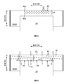
- FIG. FIG. 2 is a schematic plan view of the diaper 1 in an expanded and extended state. It is a schematic sectional drawing of the ventral side of the diaper 1. It is a schematic sectional drawing of the back of diaper 1. It is a figure showing signs that diaper 1 is worn by a wearer of a standing posture. It is a figure explaining ventilation path S2.
- FIG. 7A and FIG. 7B are diagrams for explaining the opening ratio of the ventilation hole 41.
- FIG. FIGS. 8A and 8B are diagrams illustrating the arrangement pattern of the ventilation holes 41. It is an enlarged view of the ventilation hole 41. It is an outline top view of diaper 1 of a 2nd embodiment of a deployment and extension state. It is a figure showing signs that a diaper 1 is worn to a wearer of a sleeping posture.
- the vent area can be arranged near the absorbent body on the side where more excrement is absorbed in the front-rear direction, and the air can be efficiently ventilated.
- the vent area In the front-back direction, on the side where the girth is strongly lifted, the vent area can be arranged away from the absorbent main body, and damage to the girth can be suppressed.
- This pants-type absorbent article is characterized in that the length of the front waistline portion in the up-down direction is shorter than that of the rear waistline portion.
- This pants-type absorbent article is characterized in that the front waistline portion is longer in the up-down direction than the rear waistline portion.
- a pants-type absorbent article when worn mainly by a wearer who is in a sleeping posture, the breathability is good and the breakage of the waist portion can be suppressed.
- a region above the absorbent main body in the waist portion is overlapped with the absorbent main body in the left-right direction, and is outside the absorbent main body in the left-right direction.
- a vent region extending to the underside wherein the vent region is disposed in the overlapping region and the extending region.
- a value obtained by dividing the number of the ventilation holes arranged in the overlap region by the area of the overlap region is equal to the extension.
- a pants-type absorbent article, wherein the number is larger than a value obtained by dividing the number of the ventilation holes arranged in the extension region by the area of the extension region.
- the ventilation rate can be increased efficiently by increasing the porosity of the overlapping region.
- the opening ratio of the extension region having relatively low strength without overlapping the absorbent main body in the left-right direction breakage of the waist portion can be suppressed.
- the waist portion is an upper region above the absorbent main body, and is below the upper region, and extends outward from the absorbent main body in the left-right direction.
- a second extension area that extends out, and a second air hole that penetrates at least one sheet of the waist portion is disposed in the second extension area, and the pants.
- the value obtained by dividing the number of the second ventilation holes arranged in the second extension region by the area of the second extension region in a state where the mold absorbent article is extended is the upper region. Is larger than a value obtained by dividing the number of the air holes arranged in the upper area by the area of the upper region.
- the air permeability is improved by increasing the porosity of the second extension region. Since the second extension region is hardly stretched at the time of mounting, even if the opening ratio of the second extension region is increased, breakage of the waist portion can be suppressed.
- the waist portion includes a thread-like elastic member that expands and contracts in the left-right direction, and two sheets with the thread-like elastic member interposed therebetween, and a thickness of the waist portion.
- the nonwoven fabric is arranged on one side of the two sheets in the direction, and the ventilation hole penetrates at least one of the two sheets and the nonwoven fabric, and viewed in the thickness direction, An adhesive for bonding the nonwoven fabric to the two sheets does not overlap with the ventilation holes, and is a pants-type absorbent article.
- the solidified adhesive is hardly exposed from the air holes, and a decrease in skin contact can be suppressed.
- a part of the vent hole area is covered with a nonwoven fabric in the waist portion having a shorter length in the up-down direction of the pair of waist portions. Is a pants-type absorbent article.
- the upper part of the pair of waist parts has a longer length in the up-down direction, and the upper part of the waist part is in a state where the pants-type absorbent article is extended.
- the length in the up-down direction from the lower end of the vent area to the lower end of the vent area is shorter than the length in the up-down direction from the lower end of the vent area to the upper end of the absorbent body. It is a sexual article.
- the upper part of the pair of waist parts has a shorter length in the up-down direction, and the upper part of the waist part is in a state where the pants-type absorbent article is extended.
- the length in the vertical direction from the lower end of the vent area to the upper end of the absorbent body is shorter than the length in the vertical direction from the lower end of the vent area to the lower end of the vent area.
- the vent area can be arranged closer to the absorbent main body, and the ventilation can be performed efficiently.
- the absorbent main body has an absorbent core
- the pants-type absorbent article has a shorter length in the up-down direction of the pair of waist portions.
- the vertical direction from the upper end of the absorbent main body to the upper end of the absorbent core is longer than the vertical length from the lower end of the ventilation hole region to the upper end of the absorbent main body.
- a plurality of the vents are arranged in the left-right direction and the up-down direction, and the vents adjacent in the up-down direction are It is a pants-type absorbent article characterized by being displaced in a direction.
- the vertical space between the ventilation holes is increased, and the strength of the waist portion in the vertical direction is increased, so that damage to the waist portion can be suppressed.
- a plurality of the vents are arranged in the left-right direction and the up-down direction, and the vents adjacent in the up-down direction are It is a pants-type absorbent article characterized by being arranged so as to overlap in a direction.
- the cross-sectional shape of the waist portion has a relatively uniform concavo-convex shape, and an air passage (longitudinal wrinkles) is easily formed, and the air permeability is improved.
- a region of the waist portion above the absorbent body and overlapping the absorbent body in the left-right direction is a central region in the left-right direction, and a side portion.
- the value obtained by dividing the number of the ventilation holes arranged in the central region by the area of the central region is equal to the side region.
- a small number of air holes are arranged in a short range in the vertical direction, so that the strength in the vertical direction is increased and damage to the waist portion can be suppressed.
- the waist portion includes a plurality of thread-like elastic members extending and contracting in the left-right direction arranged in the vertical direction, and the thread-like elastic members arranged in the vertical direction are arranged between the thread-like elastic members.
- the waist portion can be prevented from being torn at the waist portion by using the thread-like elastic member, and breakage of the waist portion can be suppressed.
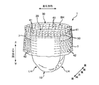
- FIG. 1 is a perspective view of a pants-type disposable diaper 1 (hereinafter, “diaper”).
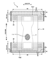
- FIG. 2 is a schematic plan view of the diaper 1 in a developed and extended state.
- FIG. 3 is a schematic sectional view of the diaper 1 on the ventral side.
- FIG. 4 is a schematic sectional view of the back side of the diaper 1.
- the diaper 1 has an up-down direction, a left-right direction, and a front-rear direction, and is formed with a waist opening BH and a pair of leg openings LH.
- the waist side is defined as the upper side
- the crotch side is defined as the lower side.
- the front-back direction the abdomen of the wearer is the front side
- the back of the wearer is the back side.
- the direction in which the materials constituting the diaper 1 are stacked is referred to as a thickness direction.
- the skin side is referred to as a thickness direction.
- the diaper 1 has an absorbent main body 10 and a pair of waist portions 20, 30, which are three members having a rectangular shape in a plan view.
- the pair of waist parts 20, 30, the one applied to the wearer's abdomen is referred to as the front waist part 20, and the one applied to the wearer's back is referred to as the rear waist part 30.
- the lateral center portion of the abdominal waistline portion 20 overlaps one end in the longitudinal direction of the absorbent main body 10, and the other longitudinal end of the absorbent main body 10
- the lateral center of the rear waistline 30 overlaps the end of the rear waistline 30.
- the unfolded diaper 1 is folded in half at the approximate center in the longitudinal direction, and the left and right lateral ends of the front waistline portion 20 and the rear waistline portion 30 are joined to form a pair of joints 7.
- the diaper 1 is in a pants-type state shown in FIG.
- a joining method using welding, an adhesive, or the like can be exemplified.
- the absorbent main body 10 includes an absorbent core 11, a liquid-permeable top sheet 12 disposed on the skin side of the absorbent core 11, and a non-skin side of the absorbent body 11. And an exterior sheet 14 disposed on the non-skin side of the back sheet 13.
- the absorbent core 11 include those in which liquid absorbent fibers such as pulp containing a super absorbent polymer (SAP) are formed into a predetermined shape.
- SAP super absorbent polymer
- the absorbent core 11 may be covered with a core wrap sheet (not shown).
- a leg elastic member that expands and contracts in the longitudinal direction of the absorbent main body 10 and a leak-proof wall that can stand on the skin side of the wearer are provided. It may be.
- the front waistline portion 20 and the rear waistline portion 30 each include two sheets 21, 22, 31, and 32, and a plurality of thread-like elastic members 23 and 33 that expand and contract in the left-right direction.
- the two sheets those arranged on the skin side in the thickness direction are referred to as skin side sheets 21 and 31, and those arranged on the non-skin side are referred to as non-skin side sheets 22 and 32.
- the plurality of thread-like elastic members 23 and 33 are arranged between the skin-side sheets 21 and 31 and the non-skin-side sheets 22 and 32 in the up-down direction, and are fixed in a state of extending in the left-right direction. Therefore, the front waistline portion 20 and the rear waistline portion 30 fit around the wearer's waistline.
- the skin-side sheets 21 and 31 and the non-skin-side sheets 22 and 32 are preferably air-permeable and flexible sheets, and examples thereof include nonwoven fabrics such as spunbond and SMS.
- Examples of the thread-like elastic members 23 and 33 include thread-like rubber and spandex.
- the diaper 1 shown in FIG. 2 is a so-called three-piece type in which the front waistline portion 20 and the rear waistline portion 30 are separated.
- a so-called two-piece type pants-type diaper having an outer member in which the front waistline portion 20 and the rear waistline portion 30 are continuous through the crotch portion and an absorbent body may be used.
- a diaper having an extended portion extending downward from the rear waistline portion 30 so as to cover the buttocks of the wearer may be used.
- a portion that vertically overlaps the joining portion 7 that joins the front waistline portion 20 and the rear waistline portion 30 is referred to as a waistline portion.
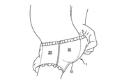
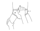
- FIG. 5 is a diagram illustrating a state in which the diaper 1 is worn on a wearer in a standing posture.
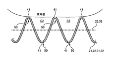
- FIG. 6 is a diagram illustrating the ventilation path S2.
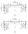
- FIG. 7A and FIG. 7B are diagrams for explaining the opening ratio of the ventilation hole 41.
- FIG. FIGS. 8A and 8B are diagrams illustrating the arrangement pattern of the ventilation holes 41.
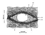
- FIG. 9 is an enlarged view of the ventilation hole 41.
- Each of the front waistline portion 20 and the rear waistline portion 30 has at least one sheet (the skin side sheets 21 and 31 or the non-skin side) of the waistline portions 20 and 30 in a region above the absorbent body 10. (The sheets 22, 32, etc.). It is assumed that at least a part of the vent area 40 in which the vent 41 is arranged overlaps the absorbent body 10 in the left-right direction.
- a virtual line La extending in the left-right direction from the left
- a virtual line Lb extending in the left-right direction from the position of the lowermost ventilation hole 41
- a virtual line Lc extending in the vertical direction from the position of the leftmost ventilation hole 41
- It is defined as a rectangular area surrounded by a virtual line Ld extending vertically from the position of the rightmost air hole 41.
- the diaper 1 has improved air permeability.
- the parts of the waist parts 20 and 30 above the absorbent main body 10 are in close contact with the wearer's waist over the entire circumference, and humid air easily accumulates. Therefore, by arranging the ventilation hole 41 above the absorbent main body 10, the moist air inside the diaper 1 can be released to the outside from the ventilation hole 41, and the stuffiness inside the diaper 1 can be further reduced. Furthermore, by arranging the vent hole region 40 (the vent hole 41) in a region overlapping in the left-right direction with the absorbent body 10 that absorbs excrement and wets, moist air can be efficiently discharged to the outside.
- the ventilation hole 41 above the absorbent main body 10 is easily recognized by the parent or the like. Therefore, the image of the diaper 1 of the present embodiment having good air permeability can be given to a parent or the like.
- the plane shape of the ventilation hole 41 is circular, but the plane shape of the ventilation hole 41 may be various shapes.
- the diaper 1 according to the first embodiment is intended to be worn by high-aged infants who mainly spend their standing posture.
- the infant in the standing posture wears the diaper 1, more urine is absorbed in the portion 111 of the absorbent core 11 closer to the abdomen, as shown in FIG. Therefore, it is desirable that moist air can be efficiently discharged from the abdominal waistline portion 20.
- the parent grasps the upper end of the waist parts 20, 30 and pulls up the diaper 1.
- the waist parts 20 and 30 are pulled up, the absorbent main body 10 joined to the waist parts 20 and 30 is also pulled up. For this reason, a portion between the upper end portions of the waist portions 20 and 30 and the absorbent body 10, which is gripped by a guardian or the like, that is, the periphery of the upper end portion of the absorbent body 10 is stretched, and a force is easily applied to the portion. .
- the length L1 (see FIG. 3) is longer than the vertical length L2 (see FIG. 4) from the lower end 40a of the ventilation hole region 40 of the rear waistline portion 30 to the rear upper end 10a2 of the absorbent main body 10. (L1 ⁇ L2).
- the vent hole 41 is arranged near the part 111 of the absorbent core 11 near the ventral side. That is, the ventilation hole 41 is arranged near the portion 111 of the absorbent core 11 where more urine is absorbed. Therefore, moist air can be efficiently discharged, and stuffiness inside the diaper 1 can be reduced.
- the ventilation hole 41 is arranged away from the periphery of the rear upper end portion of the absorbent main body 10. That is, the ventilation hole 41 is arranged away from the portion of the rear waistline portion 30 where the lifting force is strongly applied. Therefore, it is possible to prevent the rear waistline portion 30 from being torn and damaged starting from the vent hole 41.
- the length in the vertical direction from the lower end of the ventilation hole region 40 to the upper end of the absorbent body 10 may be made different before and after the diaper 1 according to the main posture of the wearer. By doing so, air can be efficiently ventilated, and breakage of the waist parts 20, 30 at the time of mounting can be suppressed.
- the measurement and comparison of the lengths L1 and L2 in the up-down direction are performed with the diaper 1 extended.
- the measurement of the length and the area described below is also performed with the diaper 1 extended.
- the state where the diaper 1 is extended is a state where the diaper 1 (the waist parts 20, 30) is extended until there is no wrinkle. More specifically, the diaper 1 is in a state in which the diaper 1 is stretched until the dimensions of the materials (for example, the skin side sheets 21 and 31) constituting the diaper 1 are equal to or close to the dimensions of the material alone. .
- the ventilation holes 41 be visible from the non-skin side of the waist parts 20, 30 in a state where the diaper 1 is extended. More preferably, in a natural state of the diaper 1 (for example, in a state where the diaper 1 is placed flat on a table or the like), the ventilation holes 41 are preferably visible from the non-skin side of the waist parts 20, 30. By doing so, the ventilation hole 41 is easily recognized by a parent or the like, and the image that the diaper 1 of the present embodiment has good air permeability can be given to the parent or the like.
- the ventilation hole 41 is large enough to be visually recognized by a guardian or the like.
- the air holes 41 penetrate the most non-skin side sheet of the waist portions 20 and 30. More preferably, the vent holes 41 penetrate all the sheets of the waist portions 20, 30. However, even if the ventilation hole 41 does not penetrate the sheet on the non-skin side, it is only necessary that the air hole 41 be visible through the sheet on the non-skin side.
- the density of the fibers around the ventilation holes 41 may be adjusted as shown in FIG. That is, the waist parts 20 and 30 have the high-density area H between the air holes 41 and the adjacent thread-like elastic members 23 and 33 in the vertical direction, and the gap between the high-density area H and the thread-like elastic members 23 and 33.
- the high-density region H has a predetermined length in the left-right direction, and the density of the nonwoven fabric fibers in the high-density region H is higher than the density of the nonwoven fabric fibers in the outer region E. I do. By doing so, the rigidity of the high-density region H is higher than the rigidity of the outer region E, and the shape of the ventilation hole 41 is easily maintained. Therefore, the visibility of the ventilation hole 41 is improved.
- the high-density region H and the outer region E are formed in the process of forming the ventilation holes 41.
- a method of forming the vent hole 41 for example, a first rotating body (not shown) provided with a plurality of pins and a heat source, and a second rotating body (not shown) provided with a plurality of holes fitted with the pins and a heat source are provided.
- a method of passing a sheet can be exemplified.
- the high-density region H is formed around the ventilation hole 41 by the pin of the first rotating body penetrating through the heated sheet.
- the comparison of the fiber density between the high-density region H and the outer region E can be performed by a known method. For example, an image obtained by enlarging the surfaces of the waist portions 20 and 30 at a magnification of about 20 to 100 times with an electron microscope or the like is acquired. Then, the number of fibers per unit area of the high-density region H and the number of fibers per unit area of the outer region E can be measured and compared. The comparison may be made visually from the enlarged image.
- regions A1 and A2 (region abcd) above the absorbent main body 10 in the waist parts 20 and 30 are overlapped with the absorbent main body 10 in the left and right direction and an overlapping region A1 (region efgh). And an extension region A2 (region abef, region cdgh) extending outside the absorbent main body 10 in the left-right direction. It is preferable that the vent area 40 is arranged not only in the overlapping area A1 but also in the extending area A2.
- the ventilation holes 41 are arranged at intervals in the left-right direction over the entire region of the waist parts 20, 30 in the left-right direction.
- the ventilation holes 41 may be arranged in the entire overlapping area A1 in the left-right direction and in a part of the extension area A2.
- the present invention is not limited to the above, and as shown in FIG. 7B, the ventilation holes 41 may be arranged only in the overlapping area A1.
- a value obtained by dividing the number of air holes 41 arranged in the overlapping region A1 by the area of the overlapping region A1 is divided by the number of air holes 41 arranged in the extending region A2 by the area of the extending region A2. It is preferable that the value be larger than the value set. That is, it is preferable that the opening ratio of the overlapping region A1 be higher than the opening ratio of the extension region A2.
- the opening ratio of the overlapping area A1 that overlaps in the left and right direction with the absorbent body 10 that absorbs excrement and is moistened is high, and moist air can be efficiently discharged to the outside.
- the extension region A2 does not overlap with the absorbent body 10 in the left-right direction, and has a lower strength than the overlap region A1. Therefore, since the opening ratio of the extension region A2 is low, breakage of the waist portions 20 and 30 during mounting can be suppressed.
- the waist parts 20 and 30 are upper regions A1 and A2 (region abcd) above the absorbent main body 10 and lower than the upper regions A1 and A2, and It has a second extension region A3 (region bfij, region dhkl) extending outside the absorbent main body 10. It is preferable that ventilation holes 42 (second ventilation holes penetrating at least one sheet of the waist portion) are arranged not only in the upper regions A1 and A2 but also in the second extension region A3. By doing so, the air permeability of the diaper 1 is improved by the more air holes 41 and 42.
- the value obtained by dividing the number of air holes 42 arranged in the second extension area A3 by the area of the second extension area A3 is the number of air holes 41 arranged in the upper areas A1 and A2. Is preferably larger than a value obtained by dividing by the area of the upper regions A1 and A2. That is, it is preferable that the opening ratio of the second extension region A3 be higher than the opening ratio of the upper regions A1 and A2.
- the second extension region A3 arranged in the left-right direction with the absorbent main body 10 is hardly stretched when the diaper 1 is attached, and thus is less likely to be damaged than the upper regions A1 and A2. Therefore, by increasing the opening ratio of the second extension region A3, the ventilation of the diaper 1 is further improved while suppressing the breakage of the waist parts 20, 30.
- the ventilation holes 41 are arranged between the thread-like elastic members 23 and 33 arranged in the vertical direction. And it is preferable that the ventilation hole 41 is not arrange
- the thread-like elastic members 23 and 33 can prevent the waistline portions 20 and 30 from starting from the ventilation holes 41 and 42. If the air holes 41 and the thread-like elastic members 23, 33 overlap, the air holes 41 are also likely to shrink due to the contraction of the thread-like elastic members 23, 33. Therefore, by arranging the ventilation hole 41 between the thread-like elastic members 23 and 33 arranged in the up-down direction, the shape and ventilation of the ventilation hole 41 are maintained. Further, the adhesive for fixing the thread-like elastic members 23 and 33 to the skin-side sheets 21 and 31 and the non-skin-side sheets 22 and 32 is less likely to be exposed from the air holes 41.
- the ventilation holes 41 may be arranged above the uppermost thread-like elastic members 23a and 33a in the waist parts 20 and 30.
- the ventilation hole 41 penetrates the skin-side sheets 21, 31 and the non-skin-side sheets 22, 32 (two sheets) with the thread-like elastic members 23, 33 interposed therebetween. By doing so, the breathability of the diaper 1 is further improved.
- L1, L2 the vertical length of the ventilation hole region 40 to the upper end of the absorbent body 10 (the front waist portion of the first embodiment).
- the upper end of the non-skin side sheet 22 included in the front waistline portion 20 is turned downward on the skin side, and the folded portion 221 covers the ventilation hole region 40.
- a cover sheet 24 (nonwoven fabric) is disposed on the diaper 1 in order to prevent the absorbent core 11 from spilling from the upper end of the absorbent main body 10.
- the cover sheet 24 is disposed on the skin side of the absorbent main body 10 so as to straddle the upper end of the absorbent main body 10.
- the cover sheet 24 may cover the vent area 40.
- vent area 40 it is preferable to cover the vent area 40 with a nonwoven fabric from the skin side. By doing so, the visibility of the ventilation hole 41 from the outside of the diaper 1 is enhanced, and the ventilation hole 41 is easily recognized by a guardian or the like.
- the waist portion having a longer vertical length L1, L2 from the lower end of the ventilation hole region 40 to the upper end of the absorbent body 10 (the rear side of the first embodiment) In the waist portion 30), the ventilation efficiency is not good, but there is little possibility of leakage from the ventilation hole 41. Therefore, it is preferable to penetrate the ventilation holes 41 from the sheet closest to the skin side to the sheet closest to the skin side.
- the upper end of the non-skin side sheet 32 is not folded back. Further, the cover sheet 34 straddling the upper end of the absorbent main body 10 is located below the ventilation holes 41. Since the ventilation holes 41 of the rear waist portion 30 are not covered with the sheet, the breathability of the diaper 1 is improved.
- one side in the thickness direction of two sheets (skin-side sheets 21, 31 and non-skin-side sheets 22, 32) with thread-like elastic members 23, 33 interposed therebetween.
- the nonwoven fabric is disposed on the sheet, it is assumed that the nonwoven fabric is bonded to two sheets with the adhesive 52.
- the folded portion 221 of the non-skin side sheet 22 is bonded to the skin side sheet 21 with an adhesive 52.
- the cover sheet 24 is bonded to the folded portion 221 of the non-skin side sheet 22 with an adhesive 52.
- the adhesive 52 does not overlap with the ventilation hole 41 when the waist parts 20 and 30 are viewed in the thickness direction. By doing so, it is possible to prevent the solidified adhesive 52 from being exposed from the air holes 41 and to prevent the waist circumference portions 20 and 30 from touching the skin. In this case, the ventilation hole 41 only needs to penetrate at least one of the skin-side sheets 21 and 31, the non-skin-side sheets 22 and 32, and the nonwoven fabric.
- a plurality of ventilation holes 41 are arranged side by side in the left-right direction and the up-down direction, and the ventilation holes 41 adjacent in the up-down direction are arranged so as to overlap in the left-right direction. .
- the vertical wrinkles 50 along the vertical direction are easily formed on the waist parts 20, 30 due to the contraction of the thread-like elastic members 23, 33. This is probably because, as shown in FIG. 6, the sheets (skin-side sheets 21, 31 and non-skin-side sheets 22, 32, etc.) tend to be deformed starting from the ventilation holes 41.
- the cross-sectional shapes of the waist portions 20 and 30 have relatively uniform irregularities, and vertical wrinkles 50 are formed.
- a ventilation path S2 space
- the humid air inside the diaper 1 can be released from the ventilation path S2 to the outside, and the diaper 1 has air permeability. Is improved.
- the ventilation holes 41 as shown in FIG. 2 to form the vertical wrinkles 50 (air passages S2).
- the ventilation path S2 can be formed near the portion 111 of the absorbent core 11 where more urine is absorbed, and the moist air can be released from the ventilation path S2.
- the positions of the ventilation holes 41 vertically adjacent to each other are aligned in the left-right direction, but it is only necessary that the vertically adjacent ventilation holes 41 partially overlap each other. Further, in FIG. 2, two rows of the vent holes 41 are formed in the vertical direction, but the number is not limited to two, and may be one row or three or more rows.
- a plurality of vents 41 are arranged in the left-right direction and the up-down direction, and the vertically adjacent vents 41 are shifted in the left-right direction. It may be. That is, the ventilation holes 41 may be arranged in a staggered manner.
- the vertical length L6 of the ventilation holes (for example, 41a and 41b) whose positions in the left-right direction overlap is longer than that in FIG. For this reason, the strength in the vertical direction of the waist parts 20 and 30 is increased, and damage to the waist parts 20 and 30 that are pulled up when the diaper 1 is mounted can be suppressed.
- a waist portion having a longer vertical length L1, L2 from the lower end of the vent region 40 to the upper end of the absorbent body 10 (the rear waist portion of the first embodiment).
- the length L4 in the vertical direction from the upper end 30a of the waist portion 30 to the lower end 40a of the vent hole area 40 is larger than the vent hole area. It is preferable that the vertical length L2 from the lower end 40a of the base 40 to the upper end 10a2 of the absorbent body 10 be shorter (L4 ⁇ L2).
- vent area 40 is located above the waist parts 20, 30. Therefore, when the diaper 1 is worn, it is difficult for the guardian or the like to catch the fingers having the waist portions 20 and 30 in the ventilation holes 41, and the waist portions 20 and 30 can be prevented from being damaged.
- a waist portion having a shorter vertical length L1, L2 from the lower end of the vent region 40 to the upper end of the absorbent body 10 (the front waist portion of the first embodiment).
- the vertical length L3 from the upper end 20a of the waist portion 20 to the lower end 40a of the vent area 40 is larger than the vertical length L3. It is preferable that the length L1 in the vertical direction from the lower end 40a to the upper end 10a1 of the absorbent main body 10 is shorter (L3> L1).
- the diaper 1 is extended in the waist portion (the front waist portion 20 of the first embodiment) in which the lengths L1 and L2 in the vertical direction from the lower end of the vent region 40 to the upper end of the absorbent main body 10 are shorter.
- the vertical length from the upper end 10a1 of the absorbent main body 10 to the upper end 11a of the absorbent core 11 is longer than the vertical length L1 from the lower end 40a of the vent area 40 to the upper end 10a1 of the absorbent main body 10.
- L5 is preferably longer (L1 ⁇ L5).
- the length in the vertical direction from the upper ends of the waist portions 20 and 30 to the vent hole region 40 is substantially the same in the front and rear directions, and the vertical length from the upper end of the waist portions 20 and 30 to the upper end of the absorbent body 10 is the same. Since the length in the direction differs between the front and rear, the length in the vertical direction from the lower end of the vent region 40 to the upper end of the absorbent body 10 differs between the front and rear.
- the present invention is not limited to this, and the vertical length from the upper ends of the waist portions 20 and 30 to the ventilation hole region 40 may be different between the front and rear.
- a region (region abgh) in the waist parts 20, 30 which is a region above the absorbent main body 10 and overlaps the absorbent main body 10 in the left-right direction is a central region A4 in the left-right direction. (Region cdef) and a side region A5 (region abcd, region efgh).
- the central region A4 is defined as a central portion when the absorbent main body 10 is divided into three in the left-right direction, and the side regions A5 are defined as portions on both outer sides of the central region A4.
- the central area A4 is particularly stretched, and a strong force is likely to be applied to the central area A4. Therefore, when the diaper 1 is extended, the value obtained by dividing the number of the ventilation holes 41 arranged in the central region A4 by the area of the central region A4 is the ventilation hole 41 arranged in the side region A5. Is preferably smaller than a value obtained by dividing the number by the area of the side region A5. In other words, by lowering the opening ratio of the central region A4, the breakage of the waist parts 20, 30 is suppressed, and by increasing the opening ratio of the side region A5, the air permeability of the diaper 1 is improved.
- the number of the ventilation holes 41 increases from the center CL of the diaper 1 to the outside in the left-right direction, and the ventilation holes 41 are arranged in a wide range in the vertical direction. That is, in the state where the diaper 1 is extended, the vertical length L7 from the uppermost ventilation hole 41 to the lowermost ventilation hole 41 arranged in the central region A4 is arranged in the side region A5. The vertical length L8 from the uppermost air hole 41 to the lowermost air hole 41 is shorter (L7 ⁇ L8). By doing so, in the central region A4, a small number of ventilation holes 41 are arranged in a short range in the vertical direction, so that the strength of the central region A4 in the vertical direction can be increased as compared with the side region A5. . Therefore, breakage of the waist parts 20, 30 can be suppressed.
- the row of the vent holes 41 extending in the left-right direction may be inclined or curved so as to protrude upward at the center in the left-right direction. That is, the length L9 in the vertical direction from the lowermost air hole 41 arranged in the central area A4 to the upper end 10a of the absorbent main body 10 is equal to the lowermost airflow arranged in the side area A5.
- the length be longer than the vertical length L10 from the pores 41 to the upper end 10a of the absorbent main body 10.
- the ventilation hole 41 is arranged away from the upper end 10a of the absorbent main body 10 in the central region A4, so that damage to the waist parts 20, 30 can be suppressed.
- FIG. 10 is a schematic plan view of the diaper 1 according to the second embodiment in an expanded and extended state.
- FIG. 11 is a diagram illustrating a state in which the diaper 1 is worn on a wearer in a sleeping position.
- the diaper 1 of the second embodiment is intended to be worn by infants of low age who mainly spend time in a sleeping posture.
- the excreted urine flows to the back side as shown in FIG. 10, and more urine is absorbed in the portion 111 of the absorbent core 11 closer to the back side. Therefore, it is desirable that moist air can be efficiently discharged from the rear waistline portion 30.
- a parent or the like first grasps the front waistline portion 20, and pulls up the diaper 1. Thereafter, the position adjustment of the rear waist portion 30 is performed in a state where the rear waist portion 30 is pulled up to some extent along with the front waist portion 20. For this reason, the front waistline portion 20 is easily pulled up strongly, and a strong force is likely to be applied around the front upper end portion of the absorbent main body 10.
- the diaper 1 of the second embodiment in a state where the diaper 1 is extended, as shown in FIG. 10, from the lower end 40 a of the vent hole region 40 of the front waistline portion 20, the upper end on the front side of the absorbent main body 10.
- the length L1 in the vertical direction up to 10a1 is longer than the length L2 in the vertical direction from the lower end 40a of the ventilation hole region 40 of the rear waist portion 30 to the upper end 10a2 on the rear side of the absorbent body 10 ( L1> L2).
- the ventilation hole 41 is arranged near the part 111 of the absorbent core 11 closer to the back side. That is, the ventilation hole 41 is arranged near the portion 111 of the absorbent core 11 where more urine is absorbed. Therefore, moist air can be efficiently discharged, and the stuffiness inside the diaper 1 can be further reduced.
- the ventilation hole 41 is arranged away from the vicinity of the upper end portion on the front side of the absorbent main body 10. That is, the ventilation hole 41 is arranged away from the portion of the front waistline portion 20 where the lifting force is strongly applied. Therefore, it is possible to prevent the front waistline portion 20 from being torn and damaged starting from the vent hole 41.
- the diaper 1 of the second embodiment has good air permeability and is not easily damaged when worn mainly by a wearer who is in a sleeping position. Therefore, the diaper 1 of the second embodiment can be suitably used as a nighttime diaper for a sleeping wearer.
- the configuration of the waist portions 20 and 30, the difference in the opening ratio depending on the region of the waist portions 20 and 30, and the vertical length from the upper end of the waist portion to the ventilation hole region are not limited to the above.
- 1 pants-type disposable diaper (pants-type absorbent article), 10 absorbent body, 11 absorbent core, 12 top sheet, 13 back sheet, 14 exterior sheet, 20 front waist part (girth part), 21 skin side sheet, 22 Non-skin side sheet, 221 folded part (non-woven fabric), 23 thread-like elastic member, 24 cover sheet (nonwoven fabric), 30 rear waist part, 31 skin side sheet, 32 non-skin side sheet, 33 a thread-like elastic member, 40 vent area, 41 vent, 42 vent (second vent) 50 vertical wrinkles, 52 adhesives,
Landscapes
- Health & Medical Sciences (AREA)
- Epidemiology (AREA)
- Engineering & Computer Science (AREA)
- Biomedical Technology (AREA)
- Heart & Thoracic Surgery (AREA)
- Vascular Medicine (AREA)
- Life Sciences & Earth Sciences (AREA)
- Animal Behavior & Ethology (AREA)
- General Health & Medical Sciences (AREA)
- Public Health (AREA)
- Veterinary Medicine (AREA)
- Nursing (AREA)
- Orthopedic Medicine & Surgery (AREA)
- Absorbent Articles And Supports Therefor (AREA)
- Orthopedics, Nursing, And Contraception (AREA)
Abstract
Description
本発明の他の特徴については、本明細書及び添付図面の記載により明らかにする。
上下方向、左右方向、及び、前後方向を有し、吸収性本体、及び、一対の胴回り部を有するパンツ型吸収性物品であって、前記胴回り部は、前記吸収性本体よりも上側の領域において、前記胴回り部が有する少なくとも1枚のシートを貫通する通気孔を有し、前記通気孔が配置されている通気孔領域の少なくとも一部は、前記左右方向において前記吸収性本体と重なっており、前記パンツ型吸収性物品を伸長させた状態において、前記前後方向における前側の前記胴回り部が有する前記通気孔領域の下端から、前記吸収性本体の前側の上端までの前記上下方向の長さと、後側の前記胴回り部が有する前記通気孔領域の下端から、前記吸収性本体の後側の上端までの前記上下方向の長さとが、異なることを特徴とするパンツ型吸収性物品である。
本発明に係るパンツ型吸収性物品として、乳幼児向けのパンツ型使い捨ておむつを例に挙げて実施形態を説明する。ただし、本発明に係るパンツ型吸収性物品は、大人向けのパンツ型使い捨ておむつ、ショーツ型の生理用ナプキン等にも適用可能である。
<<パンツ型使い捨ておむつ1の基本構成>>
図1はパンツ型使い捨ておむつ1(以下「おむつ」)の斜視図である。図2は展開かつ伸長状態のおむつ1の概略平面図である。図3はおむつ1の腹側の概略断面図である。図4はおむつ1の背側の概略断面図である。
図5は立ち姿勢の着用者におむつ1を装着する様子を示す図である。図6は通気路S2を説明する図である。図7A及び図7Bは通気孔41の開孔率を説明する図である。図8A及び図8Bは通気孔41の配置パターンを説明する図である。図9は通気孔41の拡大図である。
図10は展開かつ伸長状態の第2実施形態のおむつ1の概略平面図である。図11は寝姿勢の着用者におむつ1を装着する様子を示す図である。第2実施形態のおむつ1は、主に寝姿勢で過ごす低月齢の乳幼児を着用対象者とする。寝姿勢の乳幼児がおむつ1を着用した場合、図10に示すように、排泄尿が背側へ流れ、背側寄りの吸収性コア11の部位111において、より多くの尿が吸収される。そのため、後側胴回り部30において湿った空気を効率良く放出できることが望ましい。
10 吸収性本体、11 吸収性コア、
12 トップシート、13 バックシート、14 外装シート、
20 前側胴回り部(胴回り部)、21 肌側シート、
22 非肌側シート、221 折り返し部分(不織布)、
23 糸状弾性部材、24 カバーシート(不織布)、
30 後側胴回り部、31 肌側シート、32 非肌側シート、
33 糸状弾性部材、
40 通気孔領域、41 通気孔、42 通気孔(第2の通気孔)
50 縦皺、52 接着剤、
Claims (16)
- 上下方向、左右方向、及び、前後方向を有し、
吸収性本体、及び、一対の胴回り部を有するパンツ型吸収性物品であって、
前記胴回り部は、前記吸収性本体よりも上側の領域において、前記胴回り部が有する少なくとも1枚のシートを貫通する通気孔を有し、
前記通気孔が配置されている通気孔領域の少なくとも一部は、前記左右方向において前記吸収性本体と重なっており、
前記パンツ型吸収性物品を伸長させた状態において、
前記前後方向における前側の前記胴回り部が有する前記通気孔領域の下端から、前記吸収性本体の前側の上端までの前記上下方向の長さと、後側の前記胴回り部が有する前記通気孔領域の下端から、前記吸収性本体の後側の上端までの前記上下方向の長さとが、異なることを特徴とするパンツ型吸収性物品。 - 請求項1に記載のパンツ型吸収性物品であって、
前側の前記胴回り部の方が、後側の前記胴回り部に比べて、前記上下方向の長さが短いことを特徴とするパンツ型吸収性物品。 - 請求項1に記載のパンツ型吸収性物品であって、
前側の前記胴回り部の方が、後側の前記胴回り部に比べて、前記上下方向の長さが長いことを特徴とするパンツ型吸収性物品。 - 請求項1から3の何れか1項に記載のパンツ型吸収性物品であって、
前記胴回り部における前記吸収性本体よりも上側の領域は、
前記左右方向において前記吸収性本体と重なる重複領域と、
前記左右方向において前記吸収性本体よりも外側に延出する延出領域と、を有し、
前記通気孔領域は、前記重複領域、及び、前記延出領域に配置されていることを特徴とするパンツ型吸収性物品。 - 請求項4に記載のパンツ型吸収性物品であって、
前記パンツ型吸収性物品を伸長させた状態において、
前記重複領域に配置されている前記通気孔の数を前記重複領域の面積で除した値は、前記延出領域に配置されている前記通気孔の数を前記延出領域の面積で除した値よりも大きいことを特徴とするパンツ型吸収性物品。 - 請求項1から5の何れか1項に記載のパンツ型吸収性物品であって、
前記胴回り部は、
前記吸収性本体よりも上側の上側領域と、
前記上側領域よりも下側であり、前記左右方向において前記吸収性本体よりも外側に延出する第2の延出領域と、を有し、
前記第2の延出領域には、前記胴回り部が有する少なくとも1枚のシートを貫通する第2の通気孔が配置されており、
前記パンツ型吸収性物品を伸長させた状態において、
前記第2の延出領域に配置されている前記第2の通気孔の数を前記第2の延出領域の面積で除した値は、前記上側領域に配置されている前記通気孔の数を前記上側領域の面積で除した値よりも大きいことを特徴とするパンツ型吸収性物品。 - 請求項1から6の何れか1項に記載のパンツ型吸収性物品であって、
前記胴回り部は、前記左右方向に伸縮する糸状弾性部材と、前記糸状弾性部材を介在させた2枚のシートと、を有し、
前記胴回り部の厚さ方向において前記2枚のシートの一方側に不織布が配置されており、
前記通気孔は、前記2枚のシート及び前記不織布の少なくとも1つを貫通しており、
前記厚さ方向に見て、前記2枚のシートに前記不織布を接着する接着剤は記通気孔と重ならないことを特徴とするパンツ型吸収性物品。 - 請求項1から7の何れか1項に記載のパンツ型吸収性物品であって、
前記一対の胴回り部のうち前記上下方向の長さが短い方の前記胴回り部では、
前記通気孔領域の少なくとも一部が不織布で覆われていることを特徴とするパンツ型吸収性物品。 - 請求項1から8の何れか1項に記載のパンツ型吸収性物品であって、
前記一対の胴回り部のうち前記上下方向の長さが長い方の前記胴回り部では、
前記パンツ型吸収性物品を伸長させた状態において、前記胴回り部の上端から前記通気孔領域の下端までの前記上下方向の長さの方が、前記通気孔領域の下端から前記吸収性本体の上端までの前記上下方向の長さよりも短いことを特徴とするパンツ型吸収性物品。 - 請求項1から9の何れか1項に記載のパンツ型吸収性物品であって、
前記一対の胴回り部のうち前記上下方向の長さが短い方の前記胴回り部では、
前記パンツ型吸収性物品を伸長させた状態において、前記胴回り部の上端から前記通気孔領域の下端までの前記上下方向の長さよりも、前記通気孔領域の下端から前記吸収性本体の上端までの前記上下方向の長さの方が短いことを特徴とするパンツ型吸収性物品。 - 請求項1から10の何れか1項に記載のパンツ型吸収性物品であって、
前記吸収性本体は、吸収性コアを有し、
前記一対の胴回り部のうち前記上下方向の長さが短い方の前記胴回り部では、
前記パンツ型吸収性物品を伸長させた状態において、前記通気孔領域の下端から前記吸収性本体の上端までの前記上下方向の長さよりも、前記吸収性本体の上端から前記吸収性コアの上端までの前記上下方向の長さの方が長いことを特徴とするパンツ型吸収性物品。 - 請求項1から11の何れか1項に記載のパンツ型吸収性物品であって、
前記通気孔領域では、複数の前記通気孔が前記左右方向及び前記上下方向に並んで配置されており、
前記上下方向に隣り合う前記通気孔は、前記左右方向にずれて配置されていることを特徴とするパンツ型吸収性物品。 - 請求項1から11の何れか1項に記載のパンツ型吸収性物品であって、
前記通気孔領域では、複数の前記通気孔が前記左右方向及び前記上下方向に並んで配置されており、
前記上下方向に隣り合う前記通気孔は、前記左右方向に重なって配置されていることを特徴とするパンツ型吸収性物品。 - 請求項1から13の何れか1項に記載のパンツ型吸収性物品であって、
前記胴回り部のうち前記吸収性本体よりも上側の領域であり前記左右方向において吸収性本体と重なる領域は、前記左右方向における中央部領域、及び、側部領域を有し、
前記パンツ型吸収性物品を伸長させた状態において、
前記中央部領域に配置されている前記通気孔の数を前記中央部領域の面積で除した値は、前記側部領域に配置されている前記通気孔の数を前記側部領域の面積で除した値よりも小さいことを特徴とするパンツ型吸収性物品。 - 請求項14に記載のパンツ型吸収性物品であって、
前記パンツ型吸収性物品を伸長させた状態において、前記中央部領域に配置されている最も上側の前記通気孔から最も下側の通気孔までの前記上下方向の長さは、前記側部領域に配置されている最も上側の前記通気孔から最も下側の通気孔までの前記上下方向の長さよりも短いことを特徴とするパンツ型吸収性物品。 - 請求項1から15の何れか1項に記載のパンツ型吸収性物品であって、
前記胴回り部は、前記左右方向に伸縮する複数の糸状弾性部材を前記上下方向に並んで有し、
前記上下方向に並ぶ前記糸状弾性部材の間に前記通気孔が配置されており、
前記胴回り部において最も上側の前記糸状弾性部材よりも上側に前記通気孔が配置されていないことを特徴とするパンツ型吸収性物品。
Priority Applications (2)
| Application Number | Priority Date | Filing Date | Title |
|---|---|---|---|
| BR112020026811-9A BR112020026811B1 (pt) | 2018-06-29 | 2019-06-18 | Artigo absorvente no formato de calça |
| CN201980043996.5A CN112334109B (zh) | 2018-06-29 | 2019-06-18 | 内裤状吸收性制品 |
Applications Claiming Priority (2)
| Application Number | Priority Date | Filing Date | Title |
|---|---|---|---|
| JP2018-124407 | 2018-06-29 | ||
| JP2018124407A JP6659774B2 (ja) | 2018-06-29 | 2018-06-29 | パンツ型吸収性物品 |
Publications (1)
| Publication Number | Publication Date |
|---|---|
| WO2020004152A1 true WO2020004152A1 (ja) | 2020-01-02 |
Family
ID=68986578
Family Applications (1)
| Application Number | Title | Priority Date | Filing Date |
|---|---|---|---|
| PCT/JP2019/024136 Ceased WO2020004152A1 (ja) | 2018-06-29 | 2019-06-18 | パンツ型吸収性物品 |
Country Status (3)
| Country | Link |
|---|---|
| JP (1) | JP6659774B2 (ja) |
| CN (1) | CN112334109B (ja) |
| WO (1) | WO2020004152A1 (ja) |
Families Citing this family (2)
| Publication number | Priority date | Publication date | Assignee | Title |
|---|---|---|---|---|
| CN120678597A (zh) * | 2024-03-21 | 2025-09-23 | 尤妮佳股份有限公司 | 内裤型一次性尿布 |
| CN120771024A (zh) * | 2024-04-08 | 2025-10-14 | 尤妮佳股份有限公司 | 吸收性物品 |
Citations (6)
| Publication number | Priority date | Publication date | Assignee | Title |
|---|---|---|---|---|
| JP2015107223A (ja) * | 2013-12-04 | 2015-06-11 | 花王株式会社 | パンツ型吸収性物品 |
| WO2017085806A1 (ja) * | 2015-11-18 | 2017-05-26 | ユニ・チャーム株式会社 | 着用物品 |
| WO2017085805A1 (ja) * | 2015-11-18 | 2017-05-26 | ユニ・チャーム株式会社 | 着用物品 |
| JP2017113187A (ja) * | 2015-12-22 | 2017-06-29 | 花王株式会社 | 使い捨ておむつ |
| WO2017175288A1 (ja) * | 2016-04-05 | 2017-10-12 | ユニ・チャーム株式会社 | 吸収性物品 |
| WO2018020676A1 (ja) * | 2016-07-29 | 2018-02-01 | ユニ・チャーム株式会社 | 吸収性物品 |
Family Cites Families (5)
| Publication number | Priority date | Publication date | Assignee | Title |
|---|---|---|---|---|
| JP5270204B2 (ja) * | 2008-03-21 | 2013-08-21 | ユニ・チャーム株式会社 | 吸収性物品 |
| JP5291164B2 (ja) * | 2011-08-31 | 2013-09-18 | ユニ・チャーム株式会社 | 吸収性物品の製造装置 |
| CN202908952U (zh) * | 2012-11-19 | 2013-05-01 | 深圳全棉时代科技有限公司 | 一种腰部透气型一次性尿裤 |
| TWI743042B (zh) * | 2015-07-28 | 2021-10-21 | 山田菊夫 | 拋棄式衣物 |
| JP6144805B1 (ja) * | 2016-06-09 | 2017-06-07 | 大王製紙株式会社 | 吸収性物品 |
-
2018
- 2018-06-29 JP JP2018124407A patent/JP6659774B2/ja active Active
-
2019
- 2019-06-18 WO PCT/JP2019/024136 patent/WO2020004152A1/ja not_active Ceased
- 2019-06-18 CN CN201980043996.5A patent/CN112334109B/zh active Active
Patent Citations (6)
| Publication number | Priority date | Publication date | Assignee | Title |
|---|---|---|---|---|
| JP2015107223A (ja) * | 2013-12-04 | 2015-06-11 | 花王株式会社 | パンツ型吸収性物品 |
| WO2017085806A1 (ja) * | 2015-11-18 | 2017-05-26 | ユニ・チャーム株式会社 | 着用物品 |
| WO2017085805A1 (ja) * | 2015-11-18 | 2017-05-26 | ユニ・チャーム株式会社 | 着用物品 |
| JP2017113187A (ja) * | 2015-12-22 | 2017-06-29 | 花王株式会社 | 使い捨ておむつ |
| WO2017175288A1 (ja) * | 2016-04-05 | 2017-10-12 | ユニ・チャーム株式会社 | 吸収性物品 |
| WO2018020676A1 (ja) * | 2016-07-29 | 2018-02-01 | ユニ・チャーム株式会社 | 吸収性物品 |
Also Published As
| Publication number | Publication date |
|---|---|
| JP2020000630A (ja) | 2020-01-09 |
| CN112334109B (zh) | 2022-04-19 |
| BR112020026811A2 (pt) | 2021-03-30 |
| JP6659774B2 (ja) | 2020-03-04 |
| CN112334109A (zh) | 2021-02-05 |
Similar Documents
| Publication | Publication Date | Title |
|---|---|---|
| JP5701027B2 (ja) | 使い捨て着用物品 | |
| JP3847680B2 (ja) | おむつ | |
| JP5745246B2 (ja) | 使い捨てのパンツ型着用物品 | |
| JP5784264B1 (ja) | 使い捨てパンツ型下着及びその製造方法 | |
| CN104822348A (zh) | 一次性尿布 | |
| JP2025168588A (ja) | パンツ型吸収性物品 | |
| JP3166677U (ja) | 吸収性物品及び吸収性本体保持カバー | |
| JP6659774B2 (ja) | パンツ型吸収性物品 | |
| JP2009195647A (ja) | 吸収性物品及び吸収性本体保持カバー | |
| JP2013198754A (ja) | 使い捨ておむつ | |
| JP6419103B2 (ja) | パンツ型の吸収性物品 | |
| WO2021235281A1 (ja) | 吸収性物品 | |
| JP6128886B2 (ja) | 使い捨ておむつ | |
| JP5655479B2 (ja) | 吸収性物品の製造方法 | |
| JP4747051B2 (ja) | パンツ型使い捨ておむつ、及びパンツ型使い捨ておむつ用外装体 | |
| JP6709842B2 (ja) | 吸収性物品 | |
| TWI657806B (zh) | 用後即棄式紙尿褲 | |
| JP6051789B2 (ja) | 使い捨ておむつ及びシート部材の製造方法 | |
| JP6709843B2 (ja) | 吸収性物品 | |
| JP2016032554A (ja) | 吸収性製品 | |
| TW201914554A (zh) | 吸收性物品 | |
| JP6410702B2 (ja) | 吸収性物品 | |
| JP6380215B2 (ja) | 吸収パッド | |
| JP2017192484A (ja) | 使い捨ておむつ | |
| JP5978378B1 (ja) | 使い捨ておむつ |
Legal Events
| Date | Code | Title | Description |
|---|---|---|---|
| 121 | Ep: the epo has been informed by wipo that ep was designated in this application |
Ref document number: 19825384 Country of ref document: EP Kind code of ref document: A1 |
|
| NENP | Non-entry into the national phase |
Ref country code: DE |
|
| REG | Reference to national code |
Ref country code: BR Ref legal event code: B01A Ref document number: 112020026811 Country of ref document: BR |
|
| ENP | Entry into the national phase |
Ref document number: 112020026811 Country of ref document: BR Kind code of ref document: A2 Effective date: 20201228 |
|
| 122 | Ep: pct application non-entry in european phase |
Ref document number: 19825384 Country of ref document: EP Kind code of ref document: A1 |