WO2020003553A1 - 配線部材の固定構造 - Google Patents
配線部材の固定構造 Download PDFInfo
- Publication number
- WO2020003553A1 WO2020003553A1 PCT/JP2018/040659 JP2018040659W WO2020003553A1 WO 2020003553 A1 WO2020003553 A1 WO 2020003553A1 JP 2018040659 W JP2018040659 W JP 2018040659W WO 2020003553 A1 WO2020003553 A1 WO 2020003553A1
- Authority
- WO
- WIPO (PCT)
- Prior art keywords
- fixing
- wiring member
- fixing structure
- wiring
- locking
- Prior art date
- Legal status (The legal status is an assumption and is not a legal conclusion. Google has not performed a legal analysis and makes no representation as to the accuracy of the status listed.)
- Ceased
Links
Images



Classifications
-
- B—PERFORMING OPERATIONS; TRANSPORTING
- B60—VEHICLES IN GENERAL
- B60R—VEHICLES, VEHICLE FITTINGS, OR VEHICLE PARTS, NOT OTHERWISE PROVIDED FOR
- B60R16/00—Electric or fluid circuits specially adapted for vehicles and not otherwise provided for; Arrangement of elements of electric or fluid circuits specially adapted for vehicles and not otherwise provided for
- B60R16/02—Electric or fluid circuits specially adapted for vehicles and not otherwise provided for; Arrangement of elements of electric or fluid circuits specially adapted for vehicles and not otherwise provided for electric constitutive elements
- B60R16/0207—Wire harnesses
- B60R16/0215—Protecting, fastening and routing means therefor
-
- F—MECHANICAL ENGINEERING; LIGHTING; HEATING; WEAPONS; BLASTING
- F16—ENGINEERING ELEMENTS AND UNITS; GENERAL MEASURES FOR PRODUCING AND MAINTAINING EFFECTIVE FUNCTIONING OF MACHINES OR INSTALLATIONS; THERMAL INSULATION IN GENERAL
- F16B—DEVICES FOR FASTENING OR SECURING CONSTRUCTIONAL ELEMENTS OR MACHINE PARTS TOGETHER, e.g. NAILS, BOLTS, CIRCLIPS, CLAMPS, CLIPS OR WEDGES; JOINTS OR JOINTING
- F16B19/00—Bolts without screw-thread; Pins, including deformable elements; Rivets
- F16B19/04—Rivets; Spigots or the like fastened by riveting
- F16B19/08—Hollow rivets; Multi-part rivets
- F16B19/10—Hollow rivets; Multi-part rivets fastened by expanding mechanically
-
- F—MECHANICAL ENGINEERING; LIGHTING; HEATING; WEAPONS; BLASTING
- F16—ENGINEERING ELEMENTS AND UNITS; GENERAL MEASURES FOR PRODUCING AND MAINTAINING EFFECTIVE FUNCTIONING OF MACHINES OR INSTALLATIONS; THERMAL INSULATION IN GENERAL
- F16B—DEVICES FOR FASTENING OR SECURING CONSTRUCTIONAL ELEMENTS OR MACHINE PARTS TOGETHER, e.g. NAILS, BOLTS, CIRCLIPS, CLAMPS, CLIPS OR WEDGES; JOINTS OR JOINTING
- F16B19/00—Bolts without screw-thread; Pins, including deformable elements; Rivets
- F16B19/04—Rivets; Spigots or the like fastened by riveting
- F16B19/08—Hollow rivets; Multi-part rivets
- F16B19/10—Hollow rivets; Multi-part rivets fastened by expanding mechanically
- F16B19/1027—Multi-part rivets
- F16B19/1036—Blind rivets
- F16B19/1081—Blind rivets fastened by a drive-pin
-
- F—MECHANICAL ENGINEERING; LIGHTING; HEATING; WEAPONS; BLASTING
- F16—ENGINEERING ELEMENTS AND UNITS; GENERAL MEASURES FOR PRODUCING AND MAINTAINING EFFECTIVE FUNCTIONING OF MACHINES OR INSTALLATIONS; THERMAL INSULATION IN GENERAL
- F16B—DEVICES FOR FASTENING OR SECURING CONSTRUCTIONAL ELEMENTS OR MACHINE PARTS TOGETHER, e.g. NAILS, BOLTS, CIRCLIPS, CLAMPS, CLIPS OR WEDGES; JOINTS OR JOINTING
- F16B5/00—Joining sheets or plates, e.g. panels, to one another or to strips or bars parallel to them
- F16B5/12—Fastening strips or bars to sheets or plates, e.g. rubber strips, decorative strips for motor vehicles, by means of clips
-
- H—ELECTRICITY
- H02—GENERATION; CONVERSION OR DISTRIBUTION OF ELECTRIC POWER
- H02G—INSTALLATION OF ELECTRIC CABLES OR LINES, OR OF COMBINED OPTICAL AND ELECTRIC CABLES OR LINES
- H02G3/00—Installations of electric cables or lines or protective tubing therefor in or on buildings, equivalent structures or vehicles
- H02G3/30—Installations of cables or lines on walls, floors or ceilings
Definitions
- the present invention relates to a technique for fixing a wiring member to a planar member.
- Patent Literature 1 discloses a urethane material (also referred to as a silencer or the like) as a planar member disposed between a body at the bottom of an automobile and a floor mat for the purpose of soundproofing and smoothing of irregularities, and a wire as a wiring member A technique for burying and fixing a harness is disclosed.
- a urethane material also referred to as a silencer or the like
- a wiring member fixing structure includes a planar member provided on a vehicle, a wiring member disposed on a main surface of the planar member, and the planar member. And a locking projection provided to extend outward from the storage section; and a locking projection that fits in the storage section and extends outward to engage the inside of the planar member. And a fixing member for fixing the wiring member to the planar member.
- the fixing structure of the wiring member according to the second aspect is the fixing structure of the wiring member according to the first aspect, wherein the fixing member includes the housing portion, the locking protrusion, and the locked portion. And a second member having a protrusion extending portion and a locking portion locked to the locked portion.
- the wiring member fixing structure according to a third aspect is the wiring member fixing structure according to the second aspect, wherein the locked part is provided on an inner peripheral surface of the housing part, and the locking part Is provided on the outer peripheral surface of the projection extension.
- a wiring member fixing structure is the wiring member fixing structure according to any one of the first to third aspects, wherein the housing portion is formed in advance on a main surface of the planar member.
- the locking projection is formed so as to fit in the recess before being expanded by the projection extension.
- the wiring member fixing structure according to a fifth aspect is the wiring member fixing structure according to any one of the first to fourth aspects, wherein the planar member is formed to be softer than the locking projection.
- the locking projection is formed in a tapered shape that can pierce the planar member.
- the fixing structure for a wiring member according to a sixth aspect is the fixing structure for a wiring member according to any one of the first to fifth aspects, wherein the housing portion is formed in a circumferential direction so as to have a cylindrical shape as a whole. A plurality of divided pieces arranged in a row, and a connecting cylinder portion that circumferentially connects the plurality of divided pieces on the side opposite to the locking projections, wherein the locking projections are respectively provided at the tips of the plurality of divided pieces. It has split locking projections provided.
- the wiring member fixing structure according to a seventh aspect is the wiring member fixing structure according to any one of the first to sixth aspects, wherein the fixing member extends outward from the housing portion. And a storage portion retaining piece which is formed on the main surface of the planar member and is hooked on the main surface of the planar member.
- the wiring member fixing structure according to an eighth aspect is the wiring member fixing structure according to any one of the first to seventh aspects, wherein the fixing member extends outward from the protrusion extension. And a protrusion extension retaining piece formed as described above and hooked on an edge of the receiving portion.
- the wiring member fixing structure according to a ninth aspect is the wiring member fixing structure according to any one of the first to eighth aspects, wherein a tip end of the fixing member is provided inside the planar member. It fits.
- the locking member is fixed to the planar member by the locking projection of the fixing member being locked inside the planar member.
- the wiring member can be easily fixed to a planar member formed separately from the wiring member.
- the locking projection can be expanded and locked to the planar member.
- the expansion of the locking projection and the locking of the first member and the second member can be performed together.
- the fourth aspect it becomes easy to insert the housing portion into the concave portion from the locking projection side.
- the fixing member is easily locked to the soft planar member.
- the locking projection when the projection extension is accommodated in the housing portion, the locking projection easily expands.
- the seventh aspect it is possible to prevent the accommodating portion from coming off to the other main surface side with respect to the planar member.
- the fixing member can be prevented from coming into contact with a member such as a vehicle body panel outside the other main surface of the planar member.
- FIG. 4 is a plan view showing a fixing structure of the wiring member according to the embodiment.
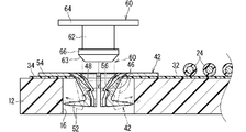
- FIG. 2 is a schematic sectional view taken along the line II-II of FIG. 1.
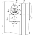
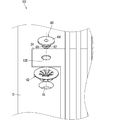
- FIG. 3 is an exploded perspective view showing a fixing structure of the wiring member according to the embodiment.
- FIG. 3 is an exploded cross-sectional view illustrating a wiring member fixing structure according to the embodiment. It is an exploded perspective view showing the 1st modification of a fixing structure of a wiring member. It is a side view which shows the 2nd modification of the fixing structure of a wiring member.
- FIG. 1 is a plan view showing a wiring member fixing structure according to the embodiment.
- FIG. 2 is a schematic sectional view taken along the line II-II of FIG.
- FIG. 3 is an exploded perspective view showing the wiring member fixing structure 1 according to the embodiment.
- FIG. 4 is an exploded cross-sectional view illustrating the wiring member fixing structure 1 according to the embodiment. Note that the imaginary line in FIG. 4 shows how the fixing member 40 is deformed.
- the wiring member fixing structure 1 is for fixing the wiring member 20 in a vehicle.
- the wiring member fixing structure 1 includes a planar member 10, a wiring member 20, and a fixing member 40.
- the planar member 10 is a member provided in a vehicle.
- the planar member 10 is a member provided on, for example, a floor, a ceiling, a side surface (door), or the like of a vehicle.
- the planar member 10 is a member provided for the purpose of soundproofing, buffering, and the like.
- the planar member 10 is, for example, a member formed softly.
- the planar member 10 is a silencer, particularly a floor silencer disposed between a floor mat and a body in a vehicle.
- the planar member 10 includes a main body 12.
- the main body 12 has one main surface 13 and the other main surface 14.
- a wiring member 20 is provided on the main surface 13.
- a concave portion 16 for accommodating the accommodating portion 44 is formed in the main surface 13 in advance.
- the recess 16 is formed in a part of the main body 12.
- the recess 16 is formed so that a part of the one main surface 13 is recessed.
- a through hole is formed as the concave portion 16. That is, the recess 16 is formed so that the other main surface 14 is also recessed on the side opposite to the one main surface 13.
- a bottomed hole in which only the one main surface 13 is recessed may be formed.
- the recess 16 is a through hole, the formation is easy.
- the concave portion 16 is a bottomed hole, a decrease in soundproofing can be suppressed.
- the main body 12 of the planar member 10 is formed in a plate shape from a material having a soundproof property.
- the main body portion 12 of the planar member 10 is integrally fixed to a chip of a resin foam such as foamed polyurethane by applying an adhesive (binder) or the like while being compressed in a steam atmosphere.
- an adhesive binder
- the concave portion 16 is formed by, for example, a press machine at the time of molding the main body 12 or after the molding.
- the method of manufacturing the main body 12 of the planar member 10 is not limited to the above.
- the main body 12 of the planar member 10 may be formed by molding a resin material such as polyurethane while foaming the material, or may be formed using a nonwoven fabric as a material.
- the main body 12 of the planar member 10 may be formed by compressing an infinite number of fibrous members. In this case, the countless fibrous members may be entangled and connected, or may be fixed by an adhesive or the like.
- a fibrous member may be a natural fiber or a chemical fiber.
- the portion of the main body 12 of the planar member 10 where the concave portion 16 is not formed is formed flat, but it is necessary to conform to the shape of the body or to partially raise the body.
- a portion having unevenness in the thickness direction may be provided.
- the wiring member 20 is a member that is connected to a component mounted on a vehicle and transmits electricity or light to and / or from the component.
- the wiring member 20 is disposed on one main surface 13 of the planar member 10.
- the wiring member 20 includes a flatly formed wiring body.
- the flat wiring body is the wiring body with sheet material 22.
- the wiring member with sheet member 22 includes a plurality of linear transmission members 24 and a sheet member 30.
- the linear transmission member 24 may be a linear member that transmits electricity or light.
- the linear transmission member 24 may be a general electric wire having a core wire and a coating around the core wire, or may be a bare conductor, a shielded wire, an enameled wire, a nichrome wire, an optical fiber, or the like.
- the linear transmission member 24 for transmitting electricity may be various signal lines or various power lines.
- the linear transmission member 24 has a transmission line main body that transmits electricity or light, and an outer cover that covers the transmission line main body.
- the linear transmission member 24 is a general electric wire 24 (hereinafter, simply referred to as an electric wire 24). That is, the electric wire 24 has the core wire 26 as the transmission line main body and the insulating coating 28 as the outer cover that covers the transmission line main body.
- the core wire 26 is composed of one or a plurality of strands.
- the strand is formed of a conductor such as copper, copper alloy, aluminum, and aluminum alloy.
- the core wire 26 is composed of a plurality of strands, the plurality of strands are preferably twisted.
- the insulating coating 28 is formed by extruding a resin material such as PVC (polyvinyl chloride) or PE (polyethylene) around the core 26.
- the electric wire 24 is a so-called round electric wire having a circular cross section.
- the plurality of electric wires 24 are disposed on the main surface of the sheet material 30.
- the route of the electric wire 24 on the sheet material 30 may be set as appropriate.
- the electric wires 24 are arranged linearly on the sheet material 30, but may be arranged to be bent, or may have both a linear portion and a bent portion. May be arranged.
- the plurality of electric wires 24 are arranged in parallel on the sheet material 30, but at least a part of the plurality of electric wires 24 may extend along different paths.
- a connector is provided at the end of the electric wire 24, and the connector is connected to a mating connector provided on a component or the like to which the wiring member 20 is connected.
- a connector is formed, for example, by housing the end of the electric wire 24 in the electric wire housing of the housing.
- the end of the electric wire 24 extends outside the sheet material 30, but the end of the electric wire 24 may be located on the sheet material 30.
- the housing may be directly fixed to the sheet material 30 or may not be fixed.
- the end of the electric wire 24 may be located on the planar member 10 or may extend outside the planar member 10.
- the sheet member 30 keeps the plurality of electric wires 24 in a flat state.
- the electric wires 24 are provided on the sheet material 30.
- the electric wire 24 and the sheet material 30 are fixed.
- a contact portion may be fixed, a non-contact portion may be fixed, or both may be used in combination.
- the term "contact portion fixing” means that the portions where the electric wires 24 and the sheet material 30 are in contact with each other are fixed together.
- the non-contact portion fixing is a fixing mode in which the contact portion is not fixed. For example, a sewing thread, another sheet material, an adhesive tape, or the like presses the electric wire 24 toward the sheet material 30 or the electric wire 24 and the sheet material. 30 and is kept in that state.
- the description will be made assuming that the electric wire 24 and the sheet material 30 are in a fixed state of the contact portion.
- the contact portion may be fixed indirectly, the contact portion may be fixed directly, or both may be used in different regions.
- the indirect fixing of the contact portion means that the electric wire 24 and the sheet material 30 are indirectly adhered and fixed via an adhesive, an adhesive, a double-sided adhesive tape, or the like provided therebetween.
- the term “contact portion directly fixed” means that the electric wire 24 and the sheet material 30 are directly adhered to each other without using an separately provided adhesive or the like.
- the direct fixing of the contact portion for example, it is conceivable that the resin contained in at least one of the electric wire 24 and the sheet material 30 is fixed by being melted by being melted.
- the description will be made assuming that the electric wire 24 and the sheet material 30 are in a state of directly fixing the contact portion.
- the resin may be melted by heat, for example, or may be melted by a solvent. That is, the state of directly fixing the contact part may be a state of directly fixing the contact part by heat or a state of directly fixing the contact part by a solvent. Preferably, the contact portion is fixed directly by heat.
- means for forming the state of directly fixing the contact portion is not particularly limited, and known means such as welding, fusion, and welding can be used.
- various welding means such as ultrasonic welding, heat and pressure welding, hot air welding, and high frequency welding can be employed.
- the electric wire 24 and the sheet material 30 are in the state of directly fixing the contact portion by the means.
- the electric wire 24 and the sheet material 30 are in the state of directly fixing the contact portion by ultrasonic welding.
- the material constituting the sheet material 30 is not particularly limited.
- the material forming the sheet material 30 may include, for example, a resin such as PVC, PE, PET (polyethylene terephthalate), or PP (polypropylene), or may include a metal such as aluminum or copper. Is also good.
- the insulating coating 28 of the electric wire 24 and the sheet material 30 are formed of the same resin material such as a compatible resin material. Is preferred.
- the sheet material 30 may have a fiber such as a woven fabric, a knitted fabric, or a non-woven fabric, or may be formed by bonding without a fiber by extrusion molding, injection molding, or the like. .
- the sheet member 30 may be a foam formed by foam molding, or may be a foam that is not foamed and has a solid cross section.
- the sheet member 30 may have a single-layer structure or a multi-layer structure.
- the sheet material 30 has a multi-layer structure, for example, it is considered that a resin layer and a resin layer are laminated. Further, for example, it is conceivable that a resin layer and a metal layer are laminated. Further, for example, it is conceivable that a metal layer and a metal layer are stacked.
- the sheet material 30 is formed by laminating a resin layer and a resin layer, layers having fibers or layers having no fibers may be laminated, or a layer having fibers and a layer having fibers may be laminated. And a layer having no.
- the sheet material 30 may be formed by bonding separately formed sheet members, or the sheet material 30 may be formed by one extrusion molding or injection molding. It may be molded.
- the fixing member 40 is a member that fixes the wiring member 20 to the planar member 10.
- the fixing member 40 includes a housing portion 44, a locking protrusion 50, and a protrusion expansion portion 62.
- the fixing member 40 further includes an accommodation portion retaining piece 54.
- the fixing member 40 further includes a protrusion extension retaining piece 64.
- the fixing member 40 is divided into a first member 42 and a second member 60.
- the first member 42 has a housing portion 44, a locking protrusion 50, and a locked portion 56.
- the first member 42 further has a retaining portion retaining piece 54.
- the second member 60 has a projection extension 62 and a locking part 66.
- the second member 60 further has a protrusion extension retaining piece 64. The first member 42 and the second member 60 are locked by locking the locking portion 66 to the locked portion 56.
- the housing 44 is inserted into the planar member 10.
- the housing portion 44 is housed in the recess 16.
- the accommodation section 44 has an insertion port 45 into which the projection extension section 62 is inserted.
- the housing portion 44 has a plurality of divided pieces 46 arranged in the circumferential direction so as to have a cylindrical shape as a whole, and a connecting tubular portion 47 connecting the plurality of divided pieces 46 in the circumferential direction.
- each of the divided pieces 46 is connected by a connecting cylinder 47 at one end thereof.
- Each of the divided pieces 46 has a thin portion at one end thereof. The thin portion functions as a hinge. In other words, when the projection extending portion 62 is inserted into the housing portion 44, mainly the thin portion is elastically deformed, and the other end is bent.
- Each divided piece 46 is formed in the same shape. Of course, some of the divided pieces 46 may be formed in different shapes from each other.
- the adjacent divided pieces 46 are arranged at intervals in the circumferential direction.
- the interval between the adjacent divided pieces 46 is set to be smaller than the circumferential dimension of the divided piece 46 around the connection portion with the connection cylinder 47.
- the interval between the adjacent divided pieces 46 may be the same as or larger than the circumferential dimension of the divided piece 46 around the connection portion with the connection cylinder portion 47. That is, the interval between the adjacent divided pieces 46 is not particularly limited, and can be appropriately set.
- the connecting cylinder 47 connects the plurality of divided pieces 46 at one end thereof.
- a portion where the plurality of divided pieces 46 are connected by the connecting cylinder portion 47 is an insertion opening 45 into which the projection extension portion 62 is inserted.
- the insertion opening 45 side may be referred to as a base end, and the side opposite to the insertion opening 45 may be referred to as a distal end.
- the inner peripheral surface of the housing portion 44 is a tapered surface 48 and functions as a guide at the time of insertion. More specifically, the housing portion 44 is formed such that the space becomes narrower as it goes further from the insertion opening 45 in a state before the protrusion expansion portion 62 is housed.
- the inner peripheral surface of each divided piece 46 is formed so as to gradually approach from the base end portion to the tip end portion. More specifically, here, the inner peripheral surface of each divided piece 46 is formed so as to gradually approach the center from the base end to the distal end.
- the projection extension portion 62 is inserted, the inner peripheral surface of each divided piece 46 is gradually pressed by the projection extension portion 62, so that the tip end of each divided piece 46 gradually spreads outward. Bend.
- the locking projection 50 is provided so as to extend outward from the housing portion 44.
- the locking projection 50 is provided at a tip of the housing portion 44.
- the locking projection 50 has divided locking projections 52 provided on the plurality of divided pieces 46, respectively.
- the division locking projection 52 is provided at the tip of the division piece 46.
- the description will be made assuming that the split locking projections 52 are provided on all the split pieces 46, but this is not an essential configuration. Some division pieces may not be provided with the division locking projection 52.
- the locking projection 50 is formed so as to fit in the recess 16 before being expanded by the projection expanding portion 62.
- all the split locking projections 52 are formed so as to fit into the recess 16 at the same time without being deformed.
- the locking projection 50 pierces the inside of the planar member 10.
- the locking projection 50 pierces a portion of the planar member 10 where no hole is formed in advance.
- each of the divided locking projections 52 penetrates the inside of the planar member 10 from the inner peripheral surface of the concave portion 16.
- each of the split locking projections 52 pierces a portion of the inner peripheral surface of the concave portion 16 where no hole is formed in advance.
- the locking projection 50 is formed in a tapered shape that can pierce the inside of the planar member 10. Thereby, the locking projection 50 can pierce a portion of the planar member 10 where no hole is formed in advance. In particular, the locking projection 50 can pierce a portion of the inner peripheral surface of the recess 16 where no hole is formed.
- the split locking projection 52 is formed in a tapered shape that can pierce the inside of the planar member 10. Thus, the split locking projection 52 can pierce a portion of the planar member 10 where a hole is not formed in advance. In particular, the split locking projection 52 can pierce a portion of the inner peripheral surface of the concave portion 16 where no hole is formed. Specifically, as shown in FIGS.
- the thickness of the divided locking projection 52 is tapered out of the thickness and the circumferential dimension.
- the circumferential dimension of the split locking projection 52 gradually increases from the base end to the distal end, but does not need to be changed.
- only the circumferential dimension of the thickness dimension and the circumferential dimension may be tapered, or both may be tapered.
- the locking projection 50 is formed so as to extend in a direction perpendicular to the insertion direction of the projection extension 62 before being expanded by the projection extension 62.
- the locking projection 50 extends toward the insertion opening 45 as shown in FIG. This makes it difficult for the fixing member 40 to come off the planar member 10.
- the split locking projection 52 extends from the distal end of the split piece 46 toward the side where the base end of the split piece 46 is located at an acute angle to the direction in which the split piece 46 extends, and As a result, the locking piece 50 behaves as described above.
- the retaining portion retaining piece 54 is formed to extend outward from the retaining portion 44 and is hooked on one main surface 13 of the planar member 10.
- the retaining portion retaining piece 54 is formed so as to extend outward from the base end of the retaining portion 44.
- the peripheral portion of the connecting tube portion 47 is extended outward as it is to form a retaining portion retaining piece 54. Therefore, the retaining portion retaining piece 54 is formed in a flange shape.
- the retaining portion retaining piece 54 is formed larger than the concave portion 16 and is hooked on a peripheral portion of the concave portion 16.
- the retaining portion retaining piece 54 is formed so as to extend in a direction perpendicular to the insertion direction of the projection extension portion 62 before being expanded by the projection extension portion 62. Therefore, before being expanded by the projection expanding portion 62, the locking projection 50 and the retaining portion retaining piece 54 are in a parallel state.
- the retaining portion retaining piece 54 functions as a retaining member that prevents the first member 42 from coming out of the planar member 10 forward in the insertion direction.
- the locking projection 50 mainly functions as a detent that prevents the first member 42 from returning to the rear in the insertion direction with respect to the planar member 10.
- the projection extension part 62 is housed in the accommodation part 44.
- the projection extension portion 62 extends the locking projection 50 outward and locks the locking projection 50 inside the planar member 10.
- the projection extension portion 62 expands the housing portion 44 and thereby expands the locking projection 50.
- the projection expanding portion 62 expands each of the divided pieces 46, thereby expanding the divided locking projections 52.
- the projection extension 62 is formed, for example, in a columnar or tubular shape. In the example shown in FIG. 2, the projection extension 62 is formed in a cylindrical shape. Therefore, although the through-hole 62h is formed in the projection extension part 62, this is not an essential configuration.
- the periphery of the distal end portion of the projection extension portion 62 is a tapered surface 63 and functions as a guide at the time of insertion. More specifically, when a further force is applied after the distal end portion of the protrusion expansion portion 62 contacts the inner peripheral surface of the housing portion 44, the protrusion expansion portion 62 is guided to the back while expanding the housing portion 44. Go.
- the projection extension retaining piece 64 is formed to extend outward from the projection extension 62, and is hooked on the edge of the housing 44. In this case, the projection extension retaining piece 64 is formed so as to extend outward from the base end of the projection extension 62.
- the protrusion extension retaining piece 64 is formed in a flange shape.
- the protrusion extension retaining piece 64 is formed to extend in a direction orthogonal to the direction in which the protrusion extension 62 extends.
- the protruding extension retaining piece 64 is formed larger than the insertion opening 45 and is hooked on the connecting cylinder portion 47 which is a peripheral portion of the insertion opening 45.
- the protrusion extension retaining piece 64 is formed larger than the concave portion 16 and is hooked on the accommodation portion retaining piece 54.
- the first member 42 and the second member 60 are locked by the locked portion 56 and the locking portion 66 being locked.
- the locked portion 56 is provided on the inner peripheral surface of the housing portion 44.
- the locking portion 66 is provided on the outer peripheral surface of the projection extending portion 62.
- a locking projection is formed as both the locked portion 56 and the locking portion 66.
- the locked portion 56 and the locking portion 66 function as detents that prevent the second member 60 from returning to the rear in the insertion direction with respect to the first member 42.
- the projection extension retaining piece 64 functions as a retaining member that prevents the second member 60 from coming out of the first member 42 in the insertion direction.
- the portion from the storage portion retaining piece 54 to the locked portion 56 of the first member 42 is formed by the protrusion expanding portion retaining piece 64 of the second member 60. It is preferable to be clamped by the portion from to the locking portion 66. This makes it difficult for the first member 42 and the second member 60 to rattle in the locked state.
- another member such as the sheet material 30 may be placed between the retaining portion retaining piece 54 and the protrusion extending portion retaining piece 64. The rattling can be suppressed.
- the distal end of the fixing member 40 is housed inside the planar member 10 in a state where the fixing member 40 is locked to the planar member 10. That is, the distal end of the fixing member 40 does not protrude outside the other main surface 14.
- the distal end portion of the first member 42 is housed inside the planar member 10 before the fixing member 40 is locked to the planar member 10. That is, the tip of the first member 42 does not protrude outside the other main surface 14.
- the height of the first member 42 from the retaining portion retaining piece 54 is smaller than the thickness of the planar member 10 at the portion where the recess 16 is formed.
- the first member 42 and the second member 60 may be integrally molded products made of, for example, metal or resin, for example, by injection molding using a mold.
- the locking projection 50 is Is also preferably formed to be hard.
- a part of the flat sheet-like wiring body (here, the sheet material 30) is sandwiched between the sheet-like member 10 and the fixing member 40 engaged with the sheet-like member 10, so that the wiring member 20 is attached to the sheet-like member 10. It is fixed.
- the sheet member 30 has a fixing piece 34 extending to the side of the electric wire disposing portion 32 on which the electric wire 24 is disposed.
- a through hole 35 is formed in the fixing piece 34.
- the fixing piece 34 is sandwiched between the retaining member 54 and the sheet member 10 in such a manner that the housing portion 44 is inserted into the through hole 35.
- the fixing pieces 34 are provided at the four corners of the sheet material 30 formed in a square shape, but this is not an essential configuration.
- the position where the fixing piece 34 is provided may be appropriately set.
- the sheet material constituting the fixing piece 34 may be separately provided on the sheet material 30 constituting the electric wire arranging portion 32, and both may be fixed.
- the accommodation portion 44 may be inserted between the electric wires 24 in the electric wire disposing portion 32 without providing the fixing piece 34.
- the through-hole 35 through which the housing portion 44 passes may not be formed in advance.
- the sheet material 30 of the sheet material 30 and the electric wire 24 is disposed on the side of the sheet member 10, but this is essential.
- the configuration is not.
- the electric wire 24 among the sheet material 30 and the electric wire 24 may be provided on the sheet member 10 side.
- step (d) is not particularly limited, and the steps (a) to (d) may be performed in any order.
- step (d) is preferably performed after steps (a) to (c). That is, the wiring member 20 is fixed to the planar member 10 by the fixing member 40, and the wiring member 20 is fixed to the wiring member fixing structure 1 (which can be regarded as a planar member module).
- the shaped member module is mounted on a vehicle. Thereby, the process of assembling the planar member 10 and the wiring member 20 to the vehicle can be facilitated.
- the fixing member 40 is fixed to the sheet member 10 by the locking projection 50 of the fixing member 40 being locked inside the sheet member 10. Is done.
- the fixing member 40 the wiring member 20 can be easily fixed to the planar member 10 formed separately from the wiring member 20.
- the fixing member 40 is divided into a first member 42 and a second member 60. At this time, the first member 42 can be locked to the planar member 10 by inserting the second member 60 into the first member 42.
- the locked portion 56 is provided on the inner peripheral surface of the housing portion 44 and the locking portion 66 is provided on the outer peripheral surface of the projection expanding portion 62, the second member 60 is inserted into the first member 42. Thereby, the expansion of the locking projection 50 and the locking of the first member 42 and the second member 60 can be performed together.
- the locking projection 50 is formed in a size that fits in the concave portion 16 before being expanded by the projection expanding portion 62, the housing portion 44 can be easily inserted into the concave portion 16 from the locking projection 50 side. .
- the locking projection 50 is formed in a tapered shape that can pierce the inside of the planar member 10, the fixing member 40 can be easily locked even if the planar member 10 is soft.
- the locking protrusion 50 is easily expanded when the protrusion expanding portion 62 is stored in the housing portion 44.
- the storage portion retaining piece 54 is provided, it is possible to prevent the storage portion 44 from coming off forward with respect to the planar member 10.
- the projection extension retaining piece 64 is provided, the projection extension 62 can be prevented from falling forward with respect to the housing section 44.
- the fixing member 40 since the distal end of the fixing member 40 does not protrude outside the other main surface 14, the fixing member 40 comes into contact with a member such as a vehicle body panel outside the other main surface 14 of the planar member 10. Can be suppressed. Further, the work of attaching the fixing member 40 to the planar member 10 can be performed in a state where the planar member 10 is placed on a flat surface. In particular, when the planar member 10 is placed on a flat surface, even if the other main surface 14 side of the concave portion 16 is closed by the flat surface, the work of attaching the fixing member 40 to the planar member 10 can be performed. it can.
- FIG. 5 is an exploded perspective view showing a first modification of the wiring member fixing structure 1.
- the fixing member 40 is fixed to the wiring member 22 with a sheet material in the fixing structure 1 of the wiring member. Is different from the mounting mode.
- the sheet material 30 is sandwiched between the first member 42 and the planar member 10, but this is essential.
- the configuration is not.
- the sheet member 30 may be sandwiched between the first member 42 and the second member 60.
- the main surface of the protrusion extension retaining piece 64 of the second member 60 may be attached to the main surface of the sheet material 30 (the main surface on which the electric wires 24 are disposed or the main surface on the back side).
- another retaining piece is provided on the first member 42 or the second member 60 in addition to the accommodation portion retaining piece 54 or the protrusion extension retaining piece 64, and one set of the first member 42 or the second member 60 is provided.
- the sheet material 30 may be sandwiched between the retaining pieces.
- the sheet material 30 is sandwiched between the first member 42 and the second member 60.
- the through-hole 135 formed in the sheet material 30 may be formed smaller than the locking portion 66.
- the main surface of the protrusion extension retaining piece 64 of the second member 60 is attached to the main surface of the sheet material 30, the main surface of the sheet material 30 and the main surface of the projection extension retaining piece 64 are bonded with an adhesive or the like. May be attached indirectly, or may be directly attached by welding or the like.
- FIG. 6 is a side view showing a second modification of the fixing structure 1 of the wiring member.
- the shape of the wiring member 220 and the manner of attaching the fixing member 240 to the wiring member 220 are different from those of the wiring member 20 in the fixing structure 1 of the wiring member.
- the mounting mode of the fixing member 40 is different from that of the first embodiment.
- the plurality of linear transmission members 24 are bundled by the binding member 38 to form the wiring member 220.
- a plurality of linear transmission members 24 are bundled in a round cross-sectional shape to form a wiring member 220.
- the type of the binding member 38 and the method of binding the plurality of linear transmission members 24 by the binding member 38 are not particularly limited.
- the adhesive tape is spirally wound around the plurality of linear transmission members 24 in a manner such as a rough winding or a double winding so that the plurality of linear transmission members 24 are bundled.
- the protective sheet material is wound in a sushi winding shape or a palm-to-shape shape and a plurality of linear transmission members 24 are bundled.
- the plurality of linear transmission members 24 are housed and bundled in a tubular member such as a corrugated tube.
- an adhesive tape or a binding band or the like is wrapped around a plurality of locations spaced apart in the longitudinal direction from the linear transmission member 24 so that the plurality of linear transmission members 24 are bundled. .
- the fixing member 240 has an extension piece 72 as a fixing portion 70 for fixing the wiring member 220.
- the extension piece 72 and the wiring member 220 are bound by the binding member 80.
- the fixing member 240 is attached to the wiring member 220.
- the extension piece 72 is provided on the second member 260. Specifically, the extension piece 72 is provided in a manner to extend along the one direction from the peripheral edge portion of the protrusion extension retaining piece 64.
- the wiring member 220 is disposed on the protrusion extension 62.
- the extension piece 72 may be provided at a position offset with respect to the projection extension 62. More specifically, the extension piece is provided in such a manner that the peripheral edge of the projection extension retaining piece 64 extends from the extension part extending along the first direction in the second direction intersecting the first direction. May be.
- a pair of the extending pieces 72 are provided in opposite directions to each other, but may be only one.
- the binding member 80 is not particularly limited.
- the binding member 80 may be provided separately from the fixing member 240, or may be integrated with the fixing member 240.
- the binding member 80 is a member provided separately from the fixing member 240, for example, an adhesive tape, a binding band, or the like may be used as the binding member 80.
- a binding band structure including, for example, a band portion and a band fixing portion is provided as the fixing portion 70 of the fixing member 240 as the binding member 80. It is possible.
- the bundling member 80 may be wound so as to be overlapped with a position of the bundling member 38 that bundles the plurality of linear transmission members 24, or may be wound around a position where there is no bundling member 38 that bundles the plurality of linear transmission members 24. It may be.
- the fixing member 70 is provided on the second member 260, however, this is not an essential configuration.
- the fixing member 70 may be provided on the first member 42.
- the fixing section 70 may be provided at a position offset with respect to the storage section 44.
- the flat wiring body has been described as being the wiring body with sheet material 22, this is not an essential configuration.
- the flat wiring body may be a so-called FFC (flexible flat cable) in which a plurality of core wires 26 are collectively covered with a single coating, or a so-called FPC (flexible print) in which a circuit is formed on a conductive foil bonded to an insulating film serving as a base. Substrate) or the like.
- the flat wiring body may be one in which a plurality of linear transmission members 24 each having a coating are collectively coated with another coating. At this time, the flat wiring body may have a structure in which a plurality of transmission line bodies or a plurality of linear transmission members are collectively sandwiched between the covering members.
- the configuration is not limited to the above.
- the outer shape of the linear transmission member 24 may be formed in a square cross section. In this case, the contact area between the sheet material 30 and the linear transmission member 24 can be easily increased.
- the wiring member 22 with a sheet material may have a cover that covers the linear transmission member 24 from the side opposite to the sheet material 30. That is, the plurality of linear transmission members 24 may be sandwiched between the sheet material 30 and the cover.
- a cover may be integral with the sheet material 30 or may be separate. When the cover is separate from the sheet material 30, the cover may be of the same type as the sheet material 30, or may be different from the sheet material 30 in material, structure, function, and the like.
- a hole through which the locking projection 50 is pierced is not formed in the planar member 10 in advance, this is not an essential configuration.
- a hole into which the locking projection 50 pierces may be formed in the planar member 10 in advance. In this case, the tip of the locking projection 50 may not be formed in a tapered shape.
- the accommodation section 44 may not be divided. Further, even when the accommodation section 44 is divided, it is not necessary to divide the accommodation section 44 into eight. It may be divided into two to seven, or may be divided into nine or more.
- a part of the configuration of the fixing member 40 may be omitted.
- the retaining portion retaining piece 54 may be omitted.
- the locking projection 50 is locked to the planar member 10 so that the first member 42 is prevented from coming off and returning from the planar member 10.
- the protrusion extension retaining piece 64 may be omitted.
- the locked portion 56 and the locking portion 66 are locked to prevent the second member 60 from coming off and returning from the first member 42.
- the positions and shapes of the locked portion 56 and the locking portion 66 are not limited to those described above.
- the locked portion 56 may be provided on the retaining portion retaining piece 54, and the locking portion 66 may be provided on the protrusion expanding portion retaining piece 64.
- the locked portion 56 may be provided at the distal end of the housing portion 44, and the locking portion 66 may be provided at the distal end of the projection extending portion 62.
- the shapes of the locked portion 56 and the locking portion 66 for example, either one may be a locking recess.
- the through-hole 35 may be formed as the locked portion 56 on the inner peripheral surface of the housing portion 44, and the locking portion 66 may be formed to be locked in the through-hole 35.
- the fixing member 40 has been described as being divided into the first member 42 having the housing portion 44 and the locking projection 50 and the second member 60 having the projection extending portion 62, but this is essential.
- the configuration is not. It may be integrally formed so as to have the accommodation portion 44, the locking projection 50, and the projection expansion portion 62 to form a fixing member.
- an integral fixing member for example, a bar-shaped projection extending portion 62 passed through the inside of the accommodation portion 44 is connected to one end of the cylindrical accommodation portion 44, and the projection extension portion 62 is pulled. It is conceivable that the intermediate portion of the housing portion 44 buckles and spreads outward to form the locking projection 50.
- the configuration is not limited to the above.
- the first member 42 and the second member 60 are connected so as not to be separated from each other.
- the second member 60 is formed so as to be inserted into the first member 42 from the locking projection 50 side.
- first member 42 and the second member 60 are connected so as not to be separated from each other, the first member 42 and the second member 60 are connected by, for example, a hinge or a long strip having flexibility. It is thought that it is. It is considered that such a hinge or a strip is provided so as to connect, for example, the edge of the retaining portion retaining piece 54 of the first member 42 and the edge of the protrusion extension retaining piece 64 of the second member 60.
- a hinge or a strip is provided so as to connect, for example, the edge of the retaining portion retaining piece 54 of the first member 42 and the edge of the protrusion extension retaining piece 64 of the second member 60.
Landscapes
- Engineering & Computer Science (AREA)
- General Engineering & Computer Science (AREA)
- Mechanical Engineering (AREA)
- Architecture (AREA)
- Civil Engineering (AREA)
- Structural Engineering (AREA)
- Installation Of Indoor Wiring (AREA)
- Details Of Indoor Wiring (AREA)
- Insertion Pins And Rivets (AREA)
- Connection Of Plates (AREA)
Abstract
配線部材とは別に形成された面状部材に配線部材を容易に固定可能な技術を提供することを目的とする。配線部材の固定構造は、車両に設けられる面状部材と、前記面状部材の主面上に配設された配線部材と、前記配線部材を前記面状部材に固定している固定用部材と、を備える。前記固定用部材は、前記面状部材に挿し込まれている収容部と、前記収容部から外方に延びるように設けられた係止突起と、前記収容部に収まり前記係止突起を外側に広げて前記面状部材の内部に係止させている突起拡張部とを含む。
Description
この発明は、配線部材を面状部材に固定する技術に関する。
特許文献1は、防音および凹凸形状の平滑化等を目的として自動車底部のボディとフロアマットとの間に配設される面状部材としてのウレタン材(サイレンサなどとも呼ばれる)に配線部材としてのワイヤーハーネスを埋設して固定する技術を開示している。
しかしながら、特許文献1に記載の技術では、ワイヤーハーネスをインサート部品としてインサート成形する必要が有る。
そこで本発明は、配線部材とは別に形成された面状部材に配線部材を容易に固定可能な技術を提供することを目的とする。
上記課題を解決するため、第1の態様に係る配線部材の固定構造は、車両に設けられる面状部材と、前記面状部材の主面上に配設された配線部材と、前記面状部材に挿し込まれている収容部と、前記収容部から外方に延びるように設けられた係止突起と、前記収容部に収まり前記係止突起を外側に広げて前記面状部材の内部に係止させている突起拡張部とを含み、前記配線部材を前記面状部材に固定している固定用部材と、を備える。
第2の態様に係る配線部材の固定構造は、第1の態様に係る配線部材の固定構造であって、前記固定用部材は、前記収容部と、前記係止突起と、被係止部とを有する第1部材と、前記突起拡張部と、前記被係止部に係止している係止部とを有する第2部材と、を備える。
第3の態様に係る配線部材の固定構造は、第2の態様に係る配線部材の固定構造であって、前記被係止部は、前記収容部の内周面に設けられ、前記係止部は、前記突起拡張部の外周面に設けられている。
第4の態様に係る配線部材の固定構造は、第1から第3のいずれか1つの態様に係る配線部材の固定構造であって、前記収容部は、前記面状部材の主面に予め形成された凹部に収められており、前記係止突起は、前記突起拡張部によって広げられる前の状態で、前記凹部に収まるように形成されている。
第5の態様に係る配線部材の固定構造は、第1から第4のいずれか1つの態様に係る配線部材の固定構造であって、前記面状部材は、前記係止突起よりも柔らかく形成され、前記係止突起は、前記面状部材に突き刺さり可能な先細り形状に形成されている。
第6の態様に係る配線部材の固定構造は、第1から第5のいずれか1つの態様に係る配線部材の固定構造であって、前記収容部は、全体に筒状を呈するように周方向に並ぶ複数の分割片と、前記係止突起と反対側において前記複数の分割片を周方向に繋げる連結筒部と、を有し、前記係止突起は、前記複数の分割片の先端にそれぞれ設けられた分割係止突起を有している。
第7の態様に係る配線部材の固定構造は、第1から第6のいずれか1つの態様に係る配線部材の固定構造であって、前記固定用部材は、前記収容部から外方に延びるように形成されて前記面状部材の主面に引っ掛かっている収容部抜止片をさらに含む。
第8の態様に係る配線部材の固定構造は、第1から第7のいずれか1つの態様に係る配線部材の固定構造であって、前記固定用部材は、前記突起拡張部から外方に延びるように形成されて前記収容部の縁部に引っ掛かっている突起拡張部抜止片をさらに含む。
第9の態様に係る配線部材の固定構造は、第1から第8のいずれか1つの態様に係る配線部材の固定構造であって、前記固定用部材の先端部が前記面状部材の内部に収まっている。
各態様によると、固定用部材の係止突起が面状部材の内部に係止することによって、固定用部材が面状部材に固定される。この固定用部材を用いることによって、配線部材とは別に形成された面状部材に配線部材を容易に固定可能となる。
第2の態様によると、第2部材を第1部材に挿し込むことによって、係止突起を拡張させて面状部材に係止させることができる。
第3の態様によると、第2部材を第1部材に挿し込むことによって、係止突起の拡張と、第1部材と第2部材との係止とを併せて行うことができる。
第4の態様によると、凹部に対して収容部を係止突起側から挿し込み容易となる。
第5の態様によると、柔らかい面状部材に対して固定用部材が係止しやすい。
第6の態様によると、収容部に突起拡張部が収められた際に係止突起が拡張しやすい。
第7の態様によると、収容部が面状部材に対して他方主面側に抜けることを抑制することができる。
第8の態様によると、突起拡張部が収容部に対して前方に抜けることを抑制することができる。
第9の態様によると、面状部材の他方主面の外方にある例えば車体パネルなどの部材に固定用部材が接触することを抑制できる。
{実施形態}
以下、実施形態に係る配線部材の固定構造1について説明する。図1は、実施形態に係る配線部材の固定構造を示す平面図である。図2は、図1のII-II線に沿って切断した概略断面図である。図3は、実施形態に係る配線部材の固定構造1を示す分解斜視図である。図4は、実施形態に係る配線部材の固定構造1を示す分解断面図である。なお、図4における仮想線は、固定用部材40が変形する様子を示している。
以下、実施形態に係る配線部材の固定構造1について説明する。図1は、実施形態に係る配線部材の固定構造を示す平面図である。図2は、図1のII-II線に沿って切断した概略断面図である。図3は、実施形態に係る配線部材の固定構造1を示す分解斜視図である。図4は、実施形態に係る配線部材の固定構造1を示す分解断面図である。なお、図4における仮想線は、固定用部材40が変形する様子を示している。
配線部材の固定構造1は、車両において配線部材20を固定するためのものである。配線部材の固定構造1は、面状部材10と、配線部材20と、固定用部材40とを備える。
<面状部材>
面状部材10は、車両に設けられる部材である。面状部材10は、例えば、車両の床、天井、側面(ドア)などに設けられる部材である。面状部材10は、防音、緩衝などの目的で設けられる部材である。面状部材10は、例えば、柔らかく形成された部材である。以下では、面状部材10がサイレンサであるもの、特に車両においてフロアマットとボディとの間に配設されるフロアサイレンサであるものとして説明する。具体的には、面状部材10は、本体部12を含む。
面状部材10は、車両に設けられる部材である。面状部材10は、例えば、車両の床、天井、側面(ドア)などに設けられる部材である。面状部材10は、防音、緩衝などの目的で設けられる部材である。面状部材10は、例えば、柔らかく形成された部材である。以下では、面状部材10がサイレンサであるもの、特に車両においてフロアマットとボディとの間に配設されるフロアサイレンサであるものとして説明する。具体的には、面状部材10は、本体部12を含む。
本体部12は、一方主面13及び他方主面14を有する。一方主面13上に配線部材20が配設されている。また一方主面13には、収容部44が収められる凹部16が予め形成されている。
凹部16は、本体部12の一部に形成されている。凹部16は、一方主面13の一部が凹むように形成されている。図2に示す例では、凹部16として貫通孔が形成されている。つまり一方主面13と反対側において他方主面14も凹むように凹部16が形成されている。もっとも凹部16としては、一方主面13のみが凹む有底穴が形成されていてもよい。凹部16が貫通孔の場合、形成が容易となる。凹部16が有底穴の場合、防音性の低下を抑制できる。
面状部材10の本体部12は、防音性を有する材料によって板状に形成されている。ここでは、面状部材10の本体部12は、発泡ポリウレタン等の樹脂発泡体のチップに、接着剤(バインダ)を塗布するなどして混在させたものを蒸気雰囲気下で圧縮させつつ一体に固着させることによって形成されるものとして説明する。かかる接着剤としてはウレタンチップ用接着剤などチップの素材に応じた周知の接着剤を用いることができる。凹部16は、本体部12の成形時又は成形後に、例えばプレス機などによって形成される。
もっとも、面状部材10の本体部12の製造方法は上記したものに限られない。例えば、面状部材10の本体部12は、ポリウレタン等の樹脂材料を発泡させつつモールド成形して形成されるものであってもよいし、不織布を材料として形成されるものであってもよい。また例えば面状部材10の本体部12は、無数の繊維状部材が圧縮されて形成されるものであってもよい。この場合、無数の繊維状部材は絡み合って結合されていてもよいし、接着剤等によって固着されていてもよい。係る繊維状部材は、天然繊維であってもよいし、化学繊維であってもよい。
図2に示す例では面状部材10の本体部12のうち凹部16が形成されていない部分は平坦に形成されているが、ボディの形状に沿わせること、又は部分的にかさ上げすること等を目的として厚み方向に凹凸を呈する部分を有していてもよい。
<配線部材>
配線部材20は、車両に搭載された部品につながれて、当該部品に及び/又は当該部品から電気又は光を伝送する部材である。配線部材20は、面状部材10の一方主面13上に配設されている。配線部材20は、偏平に形成された配線体を含む。以下では、偏平な配線体がシート材付配線体22であるものとして説明する。シート材付配線体22は、複数の線状伝送部材24と、シート材30とを含む。
配線部材20は、車両に搭載された部品につながれて、当該部品に及び/又は当該部品から電気又は光を伝送する部材である。配線部材20は、面状部材10の一方主面13上に配設されている。配線部材20は、偏平に形成された配線体を含む。以下では、偏平な配線体がシート材付配線体22であるものとして説明する。シート材付配線体22は、複数の線状伝送部材24と、シート材30とを含む。
線状伝送部材24は、電気又は光を伝送する線状の部材であればよい。例えば、線状伝送部材24は、芯線と芯線の周囲の被覆とを有する一般電線であってもよいし、裸導線、シールド線、エナメル線、ニクロム線、光ファイバ等であってもよい。電気を伝送する線状伝送部材24としては、各種信号線、各種電力線であってもよい。
ここでは線状伝送部材24は、電気又は光を伝送する伝送線本体と、伝送線本体を覆う外皮とを有する。以下では、線状伝送部材24が一般電線24(以下、単に電線24と呼ぶ)であるものとして説明する。つまり電線24は、伝送線本体としての芯線26と、伝送線本体を覆う外皮としての絶縁被覆28とを有する。
芯線26は、1本又は複数本の素線で構成される。素線は、銅、銅合金、アルミニウム、アルミニウム合金等の導体で形成される。芯線26が複数本の素線で構成される場合、複数本の素線は撚られていることが好ましい。絶縁被覆28は、PVC(ポリ塩化ビニル)、PE(ポリエチレン)などの樹脂材料が芯線26の周囲に押出成形されるなどして形成される。ここでは電線24は、横断面が円形のいわゆる丸電線である。
複数の電線24は、シート材30の主面上に配設されている。シート材30上における電線24の経路は、適宜設定されていればよい。図1に示す例では、電線24は、シート材30上において直線状に配設されているが、曲がって配設されていてもよいし、直線状部分と曲げの部分との両方を有するように配設されていてもよい。また図1に示す例では、複数の電線24は、シート材30上に並設されているが、複数の電線24の少なくとも一部が異なる経路で延びていてもよい。
電線24の端部には、例えばコネクタが設けられ、当該コネクタが、配線部材20の接続先である部品などに設けられた相手側コネクタに接続される。係るコネクタは、例えば電線24の端部がハウジングの電線収容部に収容されて形成される。図1に示す例では、電線24の端部がシート材30の外方に延出しているが、電線24の端部がシート材30上に位置していてもよい。この場合、ハウジングは、シート材30に直接固定されていてもよいし、固定されていなくてもよい。また電線24の端部は面状部材10上に位置していてもよいし、面状部材10の外方に延出していてもよい。
シート材30は、複数の電線24を偏平な状態に保つ。ここでは、シート材30上に電線24が配設される。電線24とシート材30とは、固定されている。係る固定態様として、接触部位固定であってもよいし、非接触部位固定であってもよいし、両者が併用されていてもよい。ここで接触部位固定とは、電線24とシート材30とが接触する部分がくっついて固定されているものである。また、非接触部位固定とは、接触部位固定でない固定態様であり、例えば、縫糸、別のシート材、粘着テープなどが、電線24をシート材30に向けて押え込んだり、電線24とシート材30とを挟み込んだりして、その状態に維持するものである。以下では、電線24とシート材30とが、接触部位固定の状態にあるものとして説明する。
係る接触部位固定の態様として、接触部位間接固定であってもよいし、接触部位直接固定であってもよいし、異なる領域で両者が併用されていてもよい。ここで接触部位間接固定とは、電線24とシート材30とが、その間に設けられた接着剤、粘着剤、両面粘着テープなどを介して間接的にくっついて固定されているものである。また接触部位直接固定とは、電線24とシート材30とが別に設けられた接着剤等を介さずに直接くっついて固定されているものである。接触部位直接固定では、例えば電線24とシート材30とのうち少なくとも一方に含まれる樹脂が溶かされることによってくっついて固定されることが考えられる。以下では、電線24とシート材30とが、接触部位直接固定の状態にあるものとして説明する。
係る接触部位直接固定の状態が形成されるに当たり、樹脂は、例えば、熱によって溶かされることも考えられるし、溶剤によって溶かされることも考えられる。つまり、接触部位直接固定の状態としては、熱による接触部位直接固定の状態であってもよいし、溶剤による接触部位直接固定の状態であってもよい。好ましくは、熱による接触部位直接固定の状態であるとよい。
このとき接触部位直接固定の状態を形成する手段は特に限定されるものではなく、溶着、融着、溶接等の公知の手段を用いることができる。例えば、溶着によって熱による接触部位直接固定の状態を形成する場合、超音波溶着、加熱加圧溶着、熱風溶着、高周波溶着など種々の溶着手段を採用することができる。またこれらの手段によって接触部位直接固定の状態が形成されると、電線24とシート材30とは、その手段による接触部位直接固定の状態とされる。具体的には、例えば、超音波溶着によって接触部位直接固定の状態が形成されると、電線24とシート材30とは、超音波溶着による接触部位直接固定の状態とされる。
接触部位直接固定の場合、電線24の被覆に含まれる樹脂と、シート材30に含まれる樹脂とのうちいずれか一方のみが溶けていてもよいし、両方が共に溶けていてもよい。前者の事例の場合、溶けた方の樹脂が溶けない方の樹脂の外面にくっついた状態となり、比較的はっきりした界面が形成されることがある。後者の事例の場合、両方の樹脂が混ざり合ってはっきりした界面が形成されないことがある。特に、電線24の被覆とシート材30とが、同じ樹脂材料など相溶しやすい樹脂を含む場合などに、両方の樹脂が混ざり合ってはっきりした界面が形成されないことがある。
シート材30を構成する材料は、特に限定されるものではない。シート材30を構成する材料は、例えば、PVC、PE、PET(ポリエチレンテレフタレート)、PP(ポリプロピレン)などの樹脂を含むものであってもよいし、アルミニウム又は銅などの金属を含むものであってもよい。しかしながら、電線24とシート材30とが接触部位直接固定の状態に形成されている場合、電線24の絶縁被覆28とシート材30とが同じ樹脂材料など相溶しやすい樹脂材料で形成されていることが好ましい。
シート材30は、織布、編布、不織布などの繊維を有するものであってもよいし、押出成形または射出成形などによって繊維を有さずに結合されて形成されたものであってもよい。後者の場合、シート材30は、発泡成形された発泡体であってもよいし、発泡成形されずに充実な断面を有するように成形されたものであってもよい。
またシート材30は、1層構造を有するものであってもよいし、複数層構造を有するものであってもよい。シート材30が複数層構造を有するものである場合、例えば、樹脂層と樹脂層とが積層されていることが考えられる。また例えば、樹脂層と金属層とが積層されていることが考えられる。また例えば、金属層と金属層とが積層されていることが考えられる。シート材30が、樹脂層と樹脂層とが積層されて構成されているものである場合、繊維を有する層同士又は繊維を有しない層同士が重ねられてもよいし、繊維を有する層と繊維を有しない層とが重ねられてもよい。
シート材30が複数層構造を有するものである場合、別々に成形されたシート状部材を貼り合わせてシート材30が成形されてもよいし、一の押出成形または射出成形などによってシート材30が成形されてもよい。
<固定用部材>
固定用部材40は、配線部材20を面状部材10に固定している部材である。固定用部材40は、収容部44と、係止突起50と、突起拡張部62とを含む。固定用部材40は、収容部抜止片54をさらに含む。固定用部材40は、突起拡張部抜止片64をさらに含む。
固定用部材40は、配線部材20を面状部材10に固定している部材である。固定用部材40は、収容部44と、係止突起50と、突起拡張部62とを含む。固定用部材40は、収容部抜止片54をさらに含む。固定用部材40は、突起拡張部抜止片64をさらに含む。
ここでは、固定用部材40は、第1部材42と第2部材60とに分かれている。第1部材42は、収容部44と、係止突起50と、被係止部56とを有する。第1部材42は、収容部抜止片54をさらに有する。第2部材60は、突起拡張部62と、係止部66とを有する。第2部材60は、突起拡張部抜止片64をさらに有する。係止部66が被係止部56に係止することによって第1部材42と第2部材60とが係止している。
収容部44は、面状部材10に挿し込まれている。ここでは収容部44は、凹部16に収められている。収容部44は、突起拡張部62が挿入される挿入口45を有している。ここでは収容部44は、全体に筒状を呈するように周方向に並ぶ複数の分割片46と、複数の分割片46を周方向に繋げる連結筒部47と、を有する。
ここでは周方向に8つの分割片46が並んでいる。各分割片46は、その一端部側で連結筒部47によって繋げられている。各分割片46は、その一端部に薄肉に形成された部分を有している。当該薄肉部は、ヒンジ部として機能する。つまり、収容部44に突起拡張部62が挿し込まれた際、主として薄肉部の部分が弾性変形し、これより他端部側が曲がる。各分割片46は、同じ形状に形成されている。もちろん、一部の分割片46が相互に別の形状に形成されている場合もあり得る。
隣り合う分割片46は、周方向に間隔をあけて並んでいる。図3に示す例では、隣り合う分割片46の間隔は、連結筒部47との連結部分周辺における分割片46の周方向の寸法よりも小さい間隔とされている。もちろん隣り合う分割片46の間隔は、連結筒部47との連結部分周辺における分割片46の周方向の寸法と同じかそれよりも大きい間隔であってもよい。つまり隣り合う分割片46の間隔は、特に限定されるものではなく、適宜設定することができる。
連結筒部47は、複数の分割片46をその一端部側で繋げている。収容部44において、連結筒部47によって複数の分割片46が繋がる部分が、突起拡張部62が挿入される挿入口45とされている。以下では、収容部44及び分割片46において、挿入口45側を基端部と称し、挿入口45側とは反対側を先端部と称することがある。
図4に示すように収容部44の内周面はテーパ面48とされ、挿入時のガイドとして機能する。より詳細には、収容部44は、突起拡張部62が収容される前の状態で挿入口45から奥に行くほど空間が狭くなるように形成されている。ここでは各分割片46の内周面が、基端部から先端部に向けて徐々に近づくように形成されている。より詳細にはここでは各分割片46の内周面が、基端部から先端部に向けて徐々に中心に寄るように形成されている。突起拡張部62が挿入された際に、各分割片46の内周面が突起拡張部62によって徐々に押されることによって、各分割片46の先端部が外側に徐々に広がるように薄肉部で曲がる。
係止突起50は、収容部44から外方に延びるように設けられている。係止突起50は、収容部44の先端に設けられている。係止突起50は、複数の分割片46にそれぞれ設けられた分割係止突起52を有している。分割係止突起52は、分割片46の先端に設けられている。なおここではすべての分割片46に分割係止突起52が設けられているものとして説明するが、このことは必須の構成ではない。一部の分割片には、分割係止突起52が設けられていない場合もあり得る。
係止突起50は、突起拡張部62によって広げられる前の状態で、凹部16に収まるように形成されている。ここでは、突起拡張部62によって広げられる前の状態で、全ての分割係止突起52が変形することなく同時に凹部16に収まるように形成されている。
係止突起50は、面状部材10の内部に突き刺さっている。係止突起50は、面状部材10の内部のうち予め穴の形成されていない部分に突き刺さっている。ここでは各分割係止突起52が、凹部16の内周面から面状部材10の内部に突き刺さっている。特に各分割係止突起52は、凹部16の内周面のうち予め穴の形成されていない部分に突き刺さっている。
係止突起50は、面状部材10の内部に突き刺さり可能な先細り形状に形成されている。これにより係止突起50は、面状部材10の内部のうち予め穴の形成されていない部分に突き刺さり可能である。特に係止突起50は、凹部16の内周面のうち穴の形成されていない部分に突き刺さり可能である。ここでは分割係止突起52は、面状部材10の内部に突き刺さり可能な先細り形状に形成されている。これにより分割係止突起52は、面状部材10の内部のうち予め穴の形成されていない部分に突き刺さり可能である。特に分割係止突起52は、凹部16の内周面のうち穴の形成されていない部分に突き刺さり可能である。具体的には図2、図3に示すように分割係止突起52において、厚み寸法と周方向の寸法とのうち厚み寸法のみが先細り形状に形成されている。なおここでは分割係止突起52の周方向の寸法は、基端から先端に行くにつれて次第に大きくなっているが、変わらなくてもよい。さらに分割係止突起52において、厚み寸法と周方向の寸法とのうち周方向の寸法のみが先細り形状に形成されていてもよいし、両者が先細り形状とされていてもよい。
図4に示す例では、係止突起50は、突起拡張部62によって広げられる前の状態で、突起拡張部62の挿入方向と直交する方向に延びるように形成されている。そして係止突起50は、突起拡張部62によって広げられた状態で、図2に示すように、挿入口45側に延びる。これにより固定用部材40が面状部材10から抜けにくくなっている。ここでは分割係止突起52が、分割片46の先端部から分割片46の延びる方向と鋭角をなしつつ分割片46の基端部の位置する側に向かうように延びること、及び突起拡張部62によって分割片46が曲げられることによって、係止突起50が上記のような動作をする。
収容部抜止片54は、収容部44から外方に延びるように形成されて面状部材10の一方主面13に引っ掛かっている。ここでは収容部抜止片54は、収容部44の基端部から外方に向けて延びるように形成されている。特にここでは連結筒部47の周縁部がそのまま外方に延長されて、収容部抜止片54とされている。従って収容部抜止片54は鍔状に形成されている。収容部抜止片54は、凹部16よりも大きく形成されており、凹部16の周縁部に引っ掛かっている。
図4に示すように収容部抜止片54は、突起拡張部62によって広げられる前の状態で、突起拡張部62の挿入方向と直交する方向に延びるように形成されている。従って、突起拡張部62によって広げられる前の状態で、係止突起50と収容部抜止片54とが平行な状態にある。収容部抜止片54は、面状部材10に対して第1部材42が挿入方向前方に抜けることを抑制する抜け止めとして機能する。これに対して係止突起50は、主として、面状部材10に対して第1部材42が挿入方向後方に戻ることを抑制する戻り止めとして機能する。
突起拡張部62は、収容部44に収まっている。突起拡張部62は、係止突起50を外側に広げて面状部材10の内部に係止させている。ここでは突起拡張部62は、収容部44を広げて、もって係止突起50を広げている。より詳細には突起拡張部62は、各分割片46を広げて、もって分割係止突起52を広げている。
突起拡張部62は、例えば柱状又は筒状に形成される。図2に示す例では、突起拡張部62は円筒状に形成されている。従って突起拡張部62には貫通孔62hが形成されているが、このことは必須の構成ではない。突起拡張部62の先端部の周縁部は、テーパ面63とされ、挿入時のガイドとして機能する。より詳細には、突起拡張部62の先端部が収容部44の内周面に当接した後、さらに力がかけられると、突起拡張部62は収容部44を広げつつ、奥へ案内されていく。
突起拡張部抜止片64は、突起拡張部62から外方に延びるように形成されて収容部44の縁部に引っ掛かっている。ここでは突起拡張部抜止片64は、突起拡張部62の基端部から外方に延びるように形成されている。突起拡張部抜止片64は鍔状に形成されている。突起拡張部抜止片64は、突起拡張部62の延在方向と直交する方向に延びるように形成されている。突起拡張部抜止片64は、挿入口45よりも大きく形成されており、挿入口45の周縁部である連結筒部47に引っ掛かっている。特にここでは突起拡張部抜止片64は、凹部16よりも大きく形成されて、収容部抜止片54に引っ掛かっている。
第1部材42及び第2部材60は、被係止部56と係止部66とが係止することによって、係止している。被係止部56は、収容部44の内周面に設けられている。係止部66は、突起拡張部62の外周面に設けられている。被係止部56と係止部66として共に係止凸部が形成されている。被係止部56及び係止部66は、第1部材42に対して第2部材60が挿入方向後方に戻ることを抑制する戻り止めとして機能する。突起拡張部抜止片64が第1部材42に対して第2部材60が挿入方向前方に抜けることを抑制する抜け止めとして機能する。
被係止部56と係止部66とが係止した状態で、第1部材42における収容部抜止片54から被係止部56までの部分が、第2部材60における突起拡張部抜止片64から係止部66までの部分に挟持されていることが好ましい。これにより、第1部材42及び第2部材60は、係止した状態でがたつき難くなる。なお、第1部材42及び第2部材60が、係止した状態でがたつく場合は、収容部抜止片54と突起拡張部抜止片64との間にシート材30などの別部材をかますことによってがたつきを抑制できる。
図2に示すように、固定用部材40が面状部材10に係止した状態で、固定用部材40の先端部が面状部材10の内部に収まっている。つまり、固定用部材40の先端部が他方主面14の外方に突出していない。
さらにここでは図4に示すように、固定用部材40が面状部材10に係止する前の状態で、第1部材42の先端部が面状部材10の内部に収まっている。つまり、第1部材42の先端部が他方主面14の外方に突出していない。第1部材42において収容部抜止片54からの高さ寸法が、凹部16が形成された部分における面状部材10の厚み寸法よりも小さい。
かかる第1部材42及び第2部材60は、それぞれ金属又は樹脂等を材料として、例えば金型を用いた射出成形などによって形成された一体成形品であることが考えられる。第1部材42が樹脂を材料として成形される場合であって、面状部材10のうち予め穴が形成されていない部分に係止突起50が突き刺さる場合、係止突起50は面状部材10よりも硬質に形成されているとよい。
<面状部材への配線部材の固定>
ここでは面状部材10と、これに係止する固定用部材40とによって偏平なシート状配線体の一部(ここではシート材30)を挟持することによって、配線部材20を面状部材10に固定している。より詳細には、シート材30は電線24が配設される電線配設部32の側方に延出する固定片34を有している。固定片34には貫通孔35が形成されている。そして、収容部44がこの貫通孔35に挿通される態様で、収容部抜止片54と面状部材10との間に固定片34が挟持されている。
ここでは面状部材10と、これに係止する固定用部材40とによって偏平なシート状配線体の一部(ここではシート材30)を挟持することによって、配線部材20を面状部材10に固定している。より詳細には、シート材30は電線24が配設される電線配設部32の側方に延出する固定片34を有している。固定片34には貫通孔35が形成されている。そして、収容部44がこの貫通孔35に挿通される態様で、収容部抜止片54と面状部材10との間に固定片34が挟持されている。
なお図1に示す例では、方形状に形成されたシート材30の四隅に固定片34が設けられているが、このことは必須の構成ではない。固定片34が設けられる位置は、適宜設定されていればよい。また固定片34を構成するシート材は、電線配設部32を構成するシート材30に別に設けられて、両者が固定されていてもよい。また固定片34が設けられずに、電線配設部32において電線24と電線24との間に収容部44が挿通されていてもよい。また収容部44を通す貫通孔35が予め形成されていなくてもよい。
またシート材30が電線24の片側のみを覆うシート材付配線体22において、シート材30と電線24とのうちシート材30が面状部材10側に配設されているが、このことは必須の構成ではない。シート材30と電線24とのうち電線24が面状部材10側に配設されていてもよい。
<製造工程>
配線部材の固定構造1を車両に適用するに当たり、固定用部材40を配線部材20に取付ける工程(a)と、固定用部材40を面状部材10に固定する工程(b)と、配線部材20を面状部材10に対して配策する工程(c)と、面状部材10を車両に組付ける工程(d)とが行われることが考えられる。なお、工程(a)乃至工程(c)は、配線部材の固定構造1を製造する工程である。
配線部材の固定構造1を車両に適用するに当たり、固定用部材40を配線部材20に取付ける工程(a)と、固定用部材40を面状部材10に固定する工程(b)と、配線部材20を面状部材10に対して配策する工程(c)と、面状部材10を車両に組付ける工程(d)とが行われることが考えられる。なお、工程(a)乃至工程(c)は、配線部材の固定構造1を製造する工程である。
これらの工程(a)乃至工程(d)の手順は特に限定されるものではなく、工程(a)乃至工程(d)は任意の順に行われればよい。しかしながら、工程(a)乃至工程(c)の後に工程(d)が行われることが好ましい。つまり、固定用部材40によって配線部材20が面状部材10に固定されて、これらが一体化した配線部材の固定構造1(面状部材モジュールとみなすこともできる)となった状態で、当該面状部材モジュールが車両に組付けられることが好ましい。これにより、面状部材10及び配線部材20の車両への組付工程を容易化できる。
<効果等>
以上のように構成された配線部材の固定構造1によると、固定用部材40の係止突起50が面状部材10の内部に係止することによって、固定用部材40が面状部材10に固定される。この固定用部材40を用いることによって、配線部材20とは別に形成された面状部材10に配線部材20を容易に固定可能となる。
以上のように構成された配線部材の固定構造1によると、固定用部材40の係止突起50が面状部材10の内部に係止することによって、固定用部材40が面状部材10に固定される。この固定用部材40を用いることによって、配線部材20とは別に形成された面状部材10に配線部材20を容易に固定可能となる。
また固定用部材40が第1部材42及び第2部材60に分かれている。このとき、第2部材60を第1部材42に挿し込むことによって、第1部材42を面状部材10に係止させることができる。
また被係止部56が収容部44の内周面に設けられ、係止部66が突起拡張部62の外周面に設けられているため、第2部材60を第1部材42に挿し込むことによって、係止突起50の拡張と、第1部材42と第2部材60との係止とを併せて行うことができる。
また突起拡張部62によって広げられる前の状態で係止突起50が凹部16に収まる大きさに形成されているため、凹部16に対して収容部44を係止突起50側から挿し込み容易となる。
また係止突起50が面状部材10の内部に突き刺さり可能な先細り形状に形成されているため、面状部材10が柔らかい部材でも固定用部材40が係止しやすい。
また収容部44及び係止突起50が周方向に分割されているため、収容部44に突起拡張部62が収められた際に係止突起50が拡張しやすい。
また収容部抜止片54が設けられているため、収容部44が面状部材10に対して前方に抜けることを抑制することができる。
また突起拡張部抜止片64が設けられているため、突起拡張部62が収容部44に対して前方に抜けることを抑制することができる。
また固定用部材40の先端部が他方主面14の外方に突出していないため、面状部材10の他方主面14の外方にある例えば車体パネルなどの部材に固定用部材40が接触することを抑制できる。また面状部材10を平坦面に置いた状態で、面状部材10に固定用部材40を取付ける作業を行うことができる。特に、面状部材10を平坦面に置いた状態で、凹部16の他方主面14側が当該平坦面によって塞がれていても、面状部材10に固定用部材40を取付ける作業を行うことができる。
{第1変形例}
図5は、配線部材の固定構造1の第1変形例を示す分解斜視図である。
図5は、配線部材の固定構造1の第1変形例を示す分解斜視図である。
第1変形例に係る配線部材の固定構造101において、シート材付配線体22への固定用部材40の取付態様が上記配線部材の固定構造1におけるシート材付配線体22への固定用部材40の取付態様とは異なる。
具体的には、シート材付配線体22を固定するに当たり、これまでシート材30が第1部材42と面状部材10との間に挟持されているものとして説明してきたが、このことは必須の構成ではない。例えば、シート材30が第1部材42と第2部材60との間に挟持されていてもよい。また例えば、シート材30の主面(電線24が配設される主面又はその裏側の主面)に第2部材60の突起拡張部抜止片64の主面がくっつけられるなどしてもよい。また例えば、第1部材42又は第2部材60に収容部抜止片54又は突起拡張部抜止片64のほかに抜止片がもう1つ設けられ、第1部材42又は第2部材60において1組の抜止片同士の間にシート材30が挟持されていてもよい。
図5に示す例では、シート材30が第1部材42と第2部材60との間に挟持されている。この場合、シート材30に形成される貫通孔135は、係止部66よりも小さく形成されるとよい。
シート材30の主面に第2部材60の突起拡張部抜止片64の主面がくっつけられる場合、シート材30の主面と突起拡張部抜止片64の主面とは、接着剤などを介して間接的にくっつけられていてもよいし、溶着などにより直接的にくっつけられていてもよい。
{第2変形例}
図6は、配線部材の固定構造1の第2変形例を示す側面図である。
図6は、配線部材の固定構造1の第2変形例を示す側面図である。
第2変形例に係る配線部材の固定構造201において、配線部材220の形状及び配線部材220への固定用部材240の取付態様が上記配線部材の固定構造1における配線部材20の形状及び配線部材20への固定用部材40の取付態様とは異なる。
具体的には、配線部材220の形状に関し、複数の線状伝送部材24が結束部材38によって束ねられて配線部材220とされている。ここでは複数の線状伝送部材24が丸断面形状に束ねられて配線部材220とされている。
結束部材38の種類、及び結束部材38によって複数の線状伝送部材24を束ねる方法は特に限定されるものではない。例えば、粘着テープが複数の線状伝送部材24の周りに荒巻又は二重巻などの態様で螺旋状に巻き付けられて複数の線状伝送部材24が束ねられることが考えられる。また例えば、保護シート材がすし巻き状又は合掌合せ状に巻き付けられて複数の線状伝送部材24が束ねられることが考えられる。また例えば、複数の線状伝送部材24がコルゲートチューブなどの筒部材に収容されて束ねられることが考えられる。また例えば、線状伝送部材24に対して長手方向に沿って間隔をあけた複数箇所でその周囲に粘着テープ又は結束バンド等が巻き付けられて複数の線状伝送部材24が束ねられることが考えられる。
また配線部材220への固定用部材240の取付態様に関し、固定用部材240は配線部材220を固定するための固定部70としての延出片72を有する。そして結束部材80によって延出片72と配線部材220とが結束されている。これにより固定用部材240が配線部材220に取付けられている。
図6に示す例では、係る延出片72が第2部材260に設けられている。具体的には延出片72は、突起拡張部抜止片64の周縁部から一の方向に沿って延長する態様で設けられている。配線部材220は、突起拡張部62の上に配設される。もっとも、係る延出片72は、突起拡張部62に対してオフセットした位置に設けられていてもよい。より詳細には、突起拡張部抜止片64の周縁部が第1の方向に沿って延長した延長部から当該第1の方向と交差する第2の方向に延長する態様で延出片が設けられていてもよい。
また図6に示す例では、係る延出片72が相互に反対向きに一対設けられているが、1つのみであってもよい。
係る結束部材80としては、特に限定されるものではない。結束部材80は、固定用部材240とは別に設けられていてもよいし、固定用部材240と一体化されていてもよい。結束部材80が固定用部材240と別に設けられた部材である場合、係る結束部材80として例えば粘着テープ、結束バンド等が採用されることが考えられる。また、結束部材80が固定用部材240と一体化されている場合、係る結束部材80として例えばバンド部とバンド固定部とを含む結束バンド構造が固定用部材240の固定部70として設けられていることが考えられる。
結束部材80は、複数の線状伝送部材24を束ねる結束部材38のある位置に重ねられるように巻き付けられていてもよいし、複数の線状伝送部材24を束ねる結束部材38のない位置に巻き付けられていてもよい。
もっとも図6に示す例では、第2部材260に固定部70が設けられているが、このことは必須の構成ではない。第1部材42に固定部70が設けられていてもよい。この場合、固定部70は、収容部44に対してオフセットした位置に設けられているとよい。
{その他の変形例}
これまで偏平な配線体がシート材付配線体22であるものとして説明したが、このことは必須の構成ではない。偏平な配線体は、複数の芯線26が一の被覆で一括被覆されたいわゆるFFC(フレキシブルフラットケーブル)、又はベースとなる絶縁フィルムに貼り合わされた導体箔に回路が形成されたいわゆるFPC(フレキシブルプリント基板)などであってもよい。また偏平な配線体は、それぞれ被覆を有する複数の線状伝送部材24が、さらに別の一の被覆で一括被覆されたものであってもよい。このとき偏平な配線体は、複数の伝送線本体又は複数の線状伝送部材が被覆部材に一括して挟まれている構造を有していてもよい。
これまで偏平な配線体がシート材付配線体22であるものとして説明したが、このことは必須の構成ではない。偏平な配線体は、複数の芯線26が一の被覆で一括被覆されたいわゆるFFC(フレキシブルフラットケーブル)、又はベースとなる絶縁フィルムに貼り合わされた導体箔に回路が形成されたいわゆるFPC(フレキシブルプリント基板)などであってもよい。また偏平な配線体は、それぞれ被覆を有する複数の線状伝送部材24が、さらに別の一の被覆で一括被覆されたものであってもよい。このとき偏平な配線体は、複数の伝送線本体又は複数の線状伝送部材が被覆部材に一括して挟まれている構造を有していてもよい。
また偏平な配線体がシート材付配線体22である場合でも、その構成は上記したものに限られない。線状伝送部材24の形状に関し、例えば、線状伝送部材24の外形が断面角形状に形成されていてもよい。この場合、シート材30と線状伝送部材24との接触面積を容易に増やすことができる。またシート材付配線体22が、上記シート材30とは反対側から線状伝送部材24を覆うカバーを有していてもよい。つまり複数の線状伝送部材24がシート材30とカバーとに一括して挟まれていてもよい。係るカバーとしてはシート材30と一体であってもよいし、別体であってもよい。係るカバーとしては、シート材30とは別体である場合、シート材30と同種のものであってもよいし、シート材30とは材料、構造、機能等が異なるものであってもよい。
これまで面状部材10に係止突起50が刺さる穴が予め形成されていないものとして説明してきたが、このことは必須の構成ではない。面状部材10に係止突起50が刺さる穴が予め形成されていてもよい。この場合、係止突起50の先端は先細り形状に形成されていない場合もあり得る。
これまで収容部44が分割されているものとして説明してきたが、このことは必須の構成ではない。収容部44は分割されていなくてもよい。また収容部44が分割されている場合でも8つに分割されていなくてもよい。2つ乃至7つに分割されていてもよいし、9つ以上に分割されていてもよい。
また固定用部材40の一部の構成は省略されていてもよい。例えば、収容部抜止片54が省略されていてもよい。この場合、係止突起50が面状部材10に係止することによって、面状部材10に対する第1部材42の抜け止め及び戻り止めが図られるとよい。また例えば、突起拡張部抜止片64が省略されていてもよい。この場合、被係止部56及び係止部66が係止することによって、第1部材42に対する第2部材60の抜け止め及び戻り止めが図られるとよい。
被係止部56及び係止部66の位置及び形状等は、上記したものに限られない。係止部66及び被係止部56の位置に関し、例えば、被係止部56が収容部抜止片54に設けられ、係止部66が突起拡張部抜止片64に設けられていてもよい。また例えば、被係止部56が収容部44の先端に設けられ、係止部66が突起拡張部62の先端に設けられていてもよい。また被係止部56及び係止部66の形状に関し、例えば、いずれか一方が係止凹部とされていてもよい。具体的には、例えば、収容部44の内周面に被係止部56として貫通孔35が形成され、係止部66が当該貫通孔35に係止するように形成されていてもよい。
これまで固定用部材40が、収容部44、係止突起50を有する第1部材42と、突起拡張部62を有する第2部材60とに分かれているものとして説明してきたが、このことは必須の構成ではない。収容部44、係止突起50、及び突起拡張部62を有するように一体に成形されて固定用部材とされていてもよい。このような一体的な固定部材として、例えば、筒状の収容部44の一端に、収容部44の内部に通された棒状の突起拡張部62が連なり、当該突起拡張部62が引っ張られることによって、収容部44の中間部が座屈して外側に広がり、係止突起50とされていることが考えられる。
また固定用部材40が第1部材42と第2部材60とに分かれている場合でも、その構成は上記したものに限られない。例えば、第1部材42と第2部材60とは、離れないように連結されていることが考えられる。また例えば、第1部材42に対して係止突起50側から第2部材60が挿し込まれるように形成されていることが考えられる。
第1部材42と第2部材60とが離れないように連結されている場合、第1部材42と第2部材60とは、例えば、ヒンジ又は柔軟性を有する長尺な帯状片などによって連結されていることが考えられる。かかるヒンジ又は帯状片は、例えば、第1部材42の収容部抜止片54の縁部と、第2部材60の突起拡張部抜止片64の縁部とをつなぐように設けられていることが考えられる。
なお、上記実施形態及び各変形例で説明した各構成は、相互に矛盾しない限り適宜組み合わせることができる。
以上のようにこの発明は詳細に説明されたが、上記した説明は、すべての局面において例示であって、この発明がそれに限定されるものではない。例示されていない無数の変形例が、この発明の範囲から外れることなく想定され得るものと解される。
1 配線部材の固定構造
10 面状部材
12 本体部
13 一方主面
14 他方主面
16 凹部
20 配線部材
22 シート材付配線体
24 線状伝送部材
26 芯線
28 絶縁被覆
30 シート材
32 電線配設部
34 固定片
35 貫通孔
40 固定用部材
42 第1部材
44 収容部
45 挿入口
46 分割片
47 連結筒部
50 係止突起
52 分割係止突起
54 収容部抜止片
56 被係止部
60 第2部材
62 突起拡張部
64 突起拡張部抜止片
66 係止部
10 面状部材
12 本体部
13 一方主面
14 他方主面
16 凹部
20 配線部材
22 シート材付配線体
24 線状伝送部材
26 芯線
28 絶縁被覆
30 シート材
32 電線配設部
34 固定片
35 貫通孔
40 固定用部材
42 第1部材
44 収容部
45 挿入口
46 分割片
47 連結筒部
50 係止突起
52 分割係止突起
54 収容部抜止片
56 被係止部
60 第2部材
62 突起拡張部
64 突起拡張部抜止片
66 係止部
Claims (9)
- 車両に設けられる面状部材と、
前記面状部材の主面上に配設された配線部材と、
前記面状部材に挿し込まれている収容部と、前記収容部から外方に延びるように設けられた係止突起と、前記収容部に収まり前記係止突起を外側に広げて前記面状部材の内部に係止させている突起拡張部とを含み、前記配線部材を前記面状部材に固定している固定用部材と、
を備える、配線部材の固定構造。 - 請求項1に記載の配線部材の固定構造であって、
前記固定用部材は、
前記収容部と、前記係止突起と、被係止部とを有する第1部材と、
前記突起拡張部と、前記被係止部に係止している係止部とを有する第2部材と、を備える、配線部材の固定構造。 - 請求項2に記載の配線部材の固定構造であって、
前記被係止部は、前記収容部の内周面に設けられ、
前記係止部は、前記突起拡張部の外周面に設けられている、配線部材の固定構造。 - 請求項1から請求項3のいずれか1項に記載の配線部材の固定構造であって、
前記収容部は、前記面状部材の主面に予め形成された凹部に収められており、
前記係止突起は、前記突起拡張部によって広げられる前の状態で、前記凹部に収まるように形成されている、配線部材の固定構造。 - 請求項1から請求項4のいずれか1項に記載の配線部材の固定構造であって、
前記面状部材は、前記係止突起よりも柔らかく形成され、
前記係止突起は、前記面状部材に突き刺さり可能な先細り形状に形成されている、配線部材の固定構造。 - 請求項1から請求項5のいずれか1項に記載の配線部材の固定構造であって、
前記収容部は、全体に筒状を呈するように周方向に並ぶ複数の分割片と、前記係止突起と反対側において前記複数の分割片を周方向に繋げる連結筒部と、を有し、
前記係止突起は、前記複数の分割片の先端にそれぞれ設けられた分割係止突起を有している、配線部材の固定構造。 - 請求項1から請求項6のいずれか1項に記載の配線部材の固定構造であって、
前記固定用部材は、前記収容部から外方に延びるように形成されて前記面状部材の主面に引っ掛かっている収容部抜止片をさらに含む、配線部材の固定構造。 - 請求項1から請求項7のいずれか1項に記載の配線部材の固定構造であって、
前記固定用部材は、前記突起拡張部から外方に延びるように形成されて前記収容部の縁部に引っ掛かっている突起拡張部抜止片をさらに含む、配線部材の固定構造。 - 請求項1から請求項8のいずれか1項に記載の配線部材の固定構造であって、
前記固定用部材の先端部が前記面状部材の内部に収まっている、配線部材の固定構造。
Priority Applications (2)
| Application Number | Priority Date | Filing Date | Title |
|---|---|---|---|
| US17/254,536 US11993213B2 (en) | 2018-06-27 | 2018-11-01 | Fixing structure of wiring member |
| CN201880094969.6A CN112313849B (zh) | 2018-06-27 | 2018-11-01 | 配线构件的固定结构 |
Applications Claiming Priority (2)
| Application Number | Priority Date | Filing Date | Title |
|---|---|---|---|
| JP2018-121917 | 2018-06-27 | ||
| JP2018121917A JP6601537B1 (ja) | 2018-06-27 | 2018-06-27 | 配線部材の固定構造 |
Publications (1)
| Publication Number | Publication Date |
|---|---|
| WO2020003553A1 true WO2020003553A1 (ja) | 2020-01-02 |
Family
ID=68462405
Family Applications (1)
| Application Number | Title | Priority Date | Filing Date |
|---|---|---|---|
| PCT/JP2018/040659 Ceased WO2020003553A1 (ja) | 2018-06-27 | 2018-11-01 | 配線部材の固定構造 |
Country Status (4)
| Country | Link |
|---|---|
| US (1) | US11993213B2 (ja) |
| JP (1) | JP6601537B1 (ja) |
| CN (1) | CN112313849B (ja) |
| WO (1) | WO2020003553A1 (ja) |
Cited By (1)
| Publication number | Priority date | Publication date | Assignee | Title |
|---|---|---|---|---|
| JP2022074897A (ja) * | 2020-11-05 | 2022-05-18 | 株式会社オートネットワーク技術研究所 | 配線部材及びそれを備える可動部付きの装置 |
Families Citing this family (2)
| Publication number | Priority date | Publication date | Assignee | Title |
|---|---|---|---|---|
| JP7248555B2 (ja) * | 2019-10-17 | 2023-03-29 | 林テレンプ株式会社 | 車両用フロアカーペット |
| JP7567581B2 (ja) * | 2021-03-15 | 2024-10-16 | 株式会社オートネットワーク技術研究所 | 配線モジュール |
Citations (3)
| Publication number | Priority date | Publication date | Assignee | Title |
|---|---|---|---|---|
| JP2000192924A (ja) * | 1998-12-28 | 2000-07-11 | Piolax Inc | トリム固定用クリップ |
| JP2008088998A (ja) * | 2006-09-29 | 2008-04-17 | Shirai Sangyo:Kk | 埋込部品の取付構造 |
| KR101242723B1 (ko) * | 2011-11-25 | 2013-03-11 | 인지컨트롤스 주식회사 | 케이블타이 |
Family Cites Families (19)
| Publication number | Priority date | Publication date | Assignee | Title |
|---|---|---|---|---|
| US4918261A (en) * | 1986-06-04 | 1990-04-17 | Yazaki Corporation | Flat wire harness attaching unit |
| JP2528298B2 (ja) | 1986-12-27 | 1996-08-28 | 本田技研工業株式会社 | 車輌用電装部品の組付方法 |
| JPH0333149Y2 (ja) * | 1987-08-31 | 1991-07-15 | ||
| US5339491A (en) * | 1992-11-06 | 1994-08-23 | United Technologies Automotive, Inc. | Sealed retainer grommet |
| JPH11247811A (ja) * | 1998-03-06 | 1999-09-14 | Togo Seisakusyo Corp | 防振グロメット |
| JP2000067659A (ja) * | 1998-08-18 | 2000-03-03 | Kansei Corp | フラットハーネス |
| US6443403B1 (en) | 2000-09-11 | 2002-09-03 | Panduit Corp. | Cable routing clamp and method of application |
| JP2003232318A (ja) * | 2002-02-08 | 2003-08-22 | Zen Kenchiku Sekkei Jimusho:Kk | ファスナー |
| JP2012193830A (ja) | 2011-03-18 | 2012-10-11 | Daiwa Kasei Kogyo Kk | クリップとサイレンサとの取付け構造、及びクリップ |
| JP5824282B2 (ja) * | 2011-08-10 | 2015-11-25 | 矢崎総業株式会社 | ワイヤハーネス |
| CN104428172B (zh) * | 2012-05-08 | 2016-08-17 | 矢崎总业株式会社 | 线束固定结构 |
| JP5894960B2 (ja) * | 2013-04-26 | 2016-03-30 | 住友電装株式会社 | ワイヤハーネス取付構造 |
| JP2015102166A (ja) * | 2013-11-25 | 2015-06-04 | 富士重工業株式会社 | 固定具および固定構造 |
| US10256011B2 (en) | 2014-10-31 | 2019-04-09 | Panduit Corp. | Wire harness assembly system |
| DE102014016726B3 (de) | 2014-11-13 | 2016-05-19 | Hellermann Tyton Ab | Befestigungsvorrichtung |
| JP6669996B2 (ja) * | 2018-01-22 | 2020-03-18 | 株式会社オートネットワーク技術研究所 | コネクタ |
| JP7211032B2 (ja) * | 2018-11-26 | 2023-01-24 | 株式会社オートネットワーク技術研究所 | ドア用配線モジュール |
| DE112019006982B4 (de) * | 2019-03-06 | 2025-08-21 | Autonetworks Technologies, Ltd. | Fixierungsstruktur eines Verdrahtungsbauteils |
| US11728636B2 (en) * | 2021-12-31 | 2023-08-15 | Lear Corporation | Flat flexible electrical conductor and supporting device therefor |
-
2018
- 2018-06-27 JP JP2018121917A patent/JP6601537B1/ja active Active
- 2018-11-01 WO PCT/JP2018/040659 patent/WO2020003553A1/ja not_active Ceased
- 2018-11-01 US US17/254,536 patent/US11993213B2/en active Active
- 2018-11-01 CN CN201880094969.6A patent/CN112313849B/zh active Active
Patent Citations (3)
| Publication number | Priority date | Publication date | Assignee | Title |
|---|---|---|---|---|
| JP2000192924A (ja) * | 1998-12-28 | 2000-07-11 | Piolax Inc | トリム固定用クリップ |
| JP2008088998A (ja) * | 2006-09-29 | 2008-04-17 | Shirai Sangyo:Kk | 埋込部品の取付構造 |
| KR101242723B1 (ko) * | 2011-11-25 | 2013-03-11 | 인지컨트롤스 주식회사 | 케이블타이 |
Cited By (3)
| Publication number | Priority date | Publication date | Assignee | Title |
|---|---|---|---|---|
| JP2022074897A (ja) * | 2020-11-05 | 2022-05-18 | 株式会社オートネットワーク技術研究所 | 配線部材及びそれを備える可動部付きの装置 |
| JP7552265B2 (ja) | 2020-11-05 | 2024-09-18 | 株式会社オートネットワーク技術研究所 | 配線部材を備える可動部付きの装置 |
| US12322529B2 (en) | 2020-11-05 | 2025-06-03 | Autonetworks Technologies, Ltd. | Wiring member and device with movable part provided with same |
Also Published As
| Publication number | Publication date |
|---|---|
| CN112313849B (zh) | 2022-05-10 |
| US20210276500A1 (en) | 2021-09-09 |
| JP6601537B1 (ja) | 2019-11-06 |
| CN112313849A (zh) | 2021-02-02 |
| JP2020005383A (ja) | 2020-01-09 |
| US11993213B2 (en) | 2024-05-28 |
Similar Documents
| Publication | Publication Date | Title |
|---|---|---|
| JP6562034B2 (ja) | ワイヤーハーネスの固定構造 | |
| CN111032440B (zh) | 线束的固定构造 | |
| CN113519032B (zh) | 带有固定构件的布线构件及布线构件的固定构造 | |
| JP6753551B1 (ja) | 配線部材 | |
| JP6601537B1 (ja) | 配線部材の固定構造 | |
| CN107148372A (zh) | 线束的组装方法、干扰抑制构件以及线束的组装结构 | |
| CN113015656B (zh) | 门用配线模块 | |
| CN115298919A (zh) | 配线构件 | |
| JP6673399B2 (ja) | 配線部材の固定構造 | |
| CN111065550B (zh) | 线束的固定构造 | |
| JP2020043756A (ja) | 配線部材の固定構造 | |
| JP7160059B2 (ja) | 配線部材の固定構造 | |
| JP6806225B2 (ja) | 配線部材の組付構造 | |
| WO2019244367A1 (ja) | 支持部材付配線部材 | |
| JP7419710B2 (ja) | 固定部材付き配線部材 | |
| JP7338747B2 (ja) | ワイヤーハーネスの配置構造 | |
| JP7816247B2 (ja) | 配線部材 | |
| JP2019201547A (ja) | ワイヤーハーネスの固定構造 | |
| JP6635145B2 (ja) | 配線部材の組付構造 | |
| JP2016208594A (ja) | 外装体及びワイヤーハーネス | |
| JP2020156314A (ja) | ワイヤーハーネス |
Legal Events
| Date | Code | Title | Description |
|---|---|---|---|
| 121 | Ep: the epo has been informed by wipo that ep was designated in this application |
Ref document number: 18924665 Country of ref document: EP Kind code of ref document: A1 |
|
| NENP | Non-entry into the national phase |
Ref country code: DE |
|
| 122 | Ep: pct application non-entry in european phase |
Ref document number: 18924665 Country of ref document: EP Kind code of ref document: A1 |