WO2020003446A1 - 空気調和装置 - Google Patents
空気調和装置 Download PDFInfo
- Publication number
- WO2020003446A1 WO2020003446A1 PCT/JP2018/024632 JP2018024632W WO2020003446A1 WO 2020003446 A1 WO2020003446 A1 WO 2020003446A1 JP 2018024632 W JP2018024632 W JP 2018024632W WO 2020003446 A1 WO2020003446 A1 WO 2020003446A1
- Authority
- WO
- WIPO (PCT)
- Prior art keywords
- air
- heat exchanger
- total heat
- humidity
- intake
- Prior art date
- Legal status (The legal status is an assumption and is not a legal conclusion. Google has not performed a legal analysis and makes no representation as to the accuracy of the status listed.)
- Ceased
Links
Images



Classifications
-
- F—MECHANICAL ENGINEERING; LIGHTING; HEATING; WEAPONS; BLASTING
- F24—HEATING; RANGES; VENTILATING
- F24F—AIR-CONDITIONING; AIR-HUMIDIFICATION; VENTILATION; USE OF AIR CURRENTS FOR SCREENING
- F24F1/00—Room units for air-conditioning, e.g. separate or self-contained units or units receiving primary air from a central station
-
- F—MECHANICAL ENGINEERING; LIGHTING; HEATING; WEAPONS; BLASTING
- F24—HEATING; RANGES; VENTILATING
- F24F—AIR-CONDITIONING; AIR-HUMIDIFICATION; VENTILATION; USE OF AIR CURRENTS FOR SCREENING
- F24F1/00—Room units for air-conditioning, e.g. separate or self-contained units or units receiving primary air from a central station
- F24F1/02—Self-contained room units for air-conditioning, i.e. with all apparatus for treatment installed in a common casing
-
- F—MECHANICAL ENGINEERING; LIGHTING; HEATING; WEAPONS; BLASTING
- F24—HEATING; RANGES; VENTILATING
- F24F—AIR-CONDITIONING; AIR-HUMIDIFICATION; VENTILATION; USE OF AIR CURRENTS FOR SCREENING
- F24F11/00—Control or safety arrangements
- F24F11/62—Control or safety arrangements characterised by the type of control or by internal processing, e.g. using fuzzy logic, adaptive control or estimation of values
- F24F11/63—Electronic processing
- F24F11/65—Electronic processing for selecting an operating mode
-
- F—MECHANICAL ENGINEERING; LIGHTING; HEATING; WEAPONS; BLASTING
- F24—HEATING; RANGES; VENTILATING
- F24F—AIR-CONDITIONING; AIR-HUMIDIFICATION; VENTILATION; USE OF AIR CURRENTS FOR SCREENING
- F24F7/00—Ventilation
- F24F7/04—Ventilation with ducting systems, e.g. by double walls; with natural circulation
- F24F7/06—Ventilation with ducting systems, e.g. by double walls; with natural circulation with forced air circulation, e.g. by fan positioning of a ventilator in or against a conduit
- F24F7/08—Ventilation with ducting systems, e.g. by double walls; with natural circulation with forced air circulation, e.g. by fan positioning of a ventilator in or against a conduit with separate ducts for supplied and exhausted air with provisions for reversal of the input and output systems
Definitions
- the present invention relates to an air conditioner provided with a total heat exchanger.
- Patent Document 1 takes in outside air (OA) into a room, but there is a problem that if total heat exchange is performed when there is a large difference in temperature and humidity between the room and the outside, the room environment fluctuates greatly. In addition, if the amount of outside air (OA) taken into the room is reduced in order to avoid a large fluctuation in the indoor environment, there is a problem that sufficient ventilation cannot be achieved.
- OA outside air
- the present invention has been made to solve the above problems, and provides an air conditioner capable of suppressing a change in the indoor environment due to a difference in temperature and humidity between the inside and outside of a room while securing a sufficient amount of ventilation. It is intended to be.
- the air conditioner according to the present invention includes a casing, a total heat exchanger that exchanges heat between the outside air and the atmosphere taken in the casing, and an outside air or an atmosphere taken into the casing, and the total heat exchange.
- air path switching means for switching the outflow destination of the outside air and the air taken into the casing between an air supply side and an exhaust side.
- the air path switching means can switch the outflow destination of the outside air and the air taken in the casing between the air supply side and the exhaust side, so that more ventilation than necessary is provided. By not performing this, it is possible to suppress a change in the indoor environment due to a difference in temperature and humidity between the inside and outside of the room while securing a sufficient ventilation volume.
- FIG. 2 is a configuration diagram of the air-conditioning apparatus according to Embodiment 1;
- FIG. 3 is a refrigerant circuit diagram of the flow switching device of the air-conditioning apparatus according to Embodiment 1 in a first switching state.
- FIG. 3 is a refrigerant circuit diagram of the flow path switching device of the air-conditioning apparatus according to Embodiment 1 in a second switching state.
- FIG. 3 is a configuration diagram illustrating a first switching state of an air path switching unit of the air-conditioning apparatus according to Embodiment 1.
- FIG. 3 is a configuration diagram of the air path switching unit of the air-conditioning apparatus according to Embodiment 1 in a second switching state.
- FIG. 3 is a diagram showing a control flow of the air-conditioning apparatus according to Embodiment 1.
- FIG. 4 is a configuration diagram of an air-conditioning apparatus according to Embodiment 2;
- FIG. 5 is a refrigerant circuit diagram of the air-conditioning apparatus according to Embodiment 2.
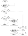
- FIG. 13 is a diagram showing a control flow of the air-conditioning apparatus according to Embodiment 3.
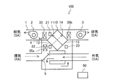
- FIG. FIG. 1 is a configuration diagram of the air-conditioning apparatus 100 according to Embodiment 1.
- the air-conditioning apparatus 100 according to Embodiment 1 includes a box-shaped casing 1 as shown in FIG.
- a drain pan 4 Inside the casing 1, the total heat exchanger 10, the first blower 2, the second blower 3, the air supply side heat exchanger 33, the first intake side heat exchanger 35a, and the exhaust side heat exchanger 35b, a drain pan 4, an air passage switching means 5, an air supply-side temperature and humidity sensor 21, a first intake-side temperature and humidity sensor 22, and a second intake-side temperature and humidity sensor 23 are provided. .
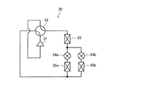
- FIG. 2 is a refrigerant circuit diagram of the air conditioner 100 according to Embodiment 1 in which the flow path switching device 32 is in the first switching state.
- FIG. 3 is a refrigerant circuit diagram of the air conditioner 100 according to Embodiment 1 in which the flow path switching device 32 is in the second switching state.
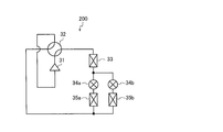
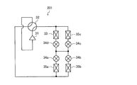
- the air conditioner 100 includes a refrigerant circuit 200 through which the refrigerant circulates, as shown in FIGS. 2 and 3.
- the compressor 31, the flow path switching device 32, the air supply side heat exchanger 33, the first intake side expansion device 34a, and the first intake side heat exchanger 35a are sequentially connected by pipes.
- the exhaust-side expansion device 34b and the exhaust-side heat exchanger 35b which are connected in series, are connected in parallel with the first intake-side expansion device 34a and the first intake-side heat exchanger 35a. ,It is configured.
- the total heat exchanger 10 has a supply-side outlet 11, an exhaust-side outlet 14, a supply-side inlet 13, and an exhaust-side inlet 12, and air flowing from the supply-side inlet 13 to the supply-side outlet 11 (hereinafter, referred to as supply).
- supply air flowing from the supply-side inlet 13 to the supply-side outlet 11
- air flowing out to the exhaust side air flowing out to the exhaust side
- One of the air flowing out to the air supply side and the air flowing out to the exhaust side is outside air (OA) and the other is air (RA).
- the first blower 2 takes in outside air (OA) or ambient air (RA) into the casing 1, and after performing total heat exchange in the total heat exchanger 10, supplies the air as air supply (SA) to a room that is a space to be air-conditioned. Things.
- the second blower 3 takes in outside air (OA) or ambient air (RA) into the casing 1, and after performing total heat exchange in the total heat exchanger 10, discharges the exhaust air (EA) to the outside of the room.
- the first blower 2 is arranged downstream of the supply-side outlet 11 and the second blower 3 is arranged downstream of the exhaust-side outlet 14.
- the present invention is not limited to this.
- the first blower 2 is disposed on the upstream side of the air supply side inlet 13 and downstream of the air path switching means 5, and the second blower 3 is located upstream of the exhaust side inlet 12 and downstream of the air path switching means 5. It may be arranged.
- one of the first blower 2 and the second blower 3 is arranged on the upstream side of the air path switching means 5 and on the air intake (RA) intake side, and the other is on the upstream side of the air path switching means 5 and It may be arranged on the outside air (OA) intake side.
- the first blower 2 or the second blower 3 arranged on the upstream side of the air path switching means 5 and on the air (RA) intake side takes in the air (RA) into the casing 1 and performs total heat exchange. After the total heat exchange in the vessel 10, the air is supplied to a room which is a space to be air-conditioned as air supply (SA), or is discharged outside as air (EA).
- the first blower 2 or the second blower 3 arranged on the upstream side of the air passage switching means 5 and on the outside air (OA) intake side takes in the outside air (OA) into the casing 1, and After the total heat exchange, the air is supplied as air supply (SA) into a room which is a space to be air-conditioned, or is discharged outside as air (EA).
- SA air supply
- EA discharged outside as air
- the air supply side heat exchanger 33 is provided on the downstream side of the air supply side outlet 11 of the total heat exchanger 10, and causes the air and the refrigerant flowing out of the air supply side outlet 11 of the total heat exchanger 10 to exchange heat with the refrigerant.
- the temperature and humidity of the supply air (SA) are adjusted.
- the air supply side heat exchanger 33 directly acts on dehumidification and humidification of the air supply (SA).
- the first intake-side heat exchanger 35a is provided on the upstream side of the exhaust-side inlet 12 of the total heat exchanger 10, and heats the outside air (OA) or the air (RA) taken into the casing 1 and the refrigerant. The temperature and humidity of the air flowing into the exhaust-side inlet 12 of the total heat exchanger 10 are adjusted. The first intake heat exchanger 35a promotes or suppresses the exchange of humidity between the air flowing out to the air supply side and the air flowing out to the exhaust side.
- the exhaust-side heat exchanger 35b is provided on the downstream side of the exhaust-side outlet 14 of the total heat exchanger 10, and causes the air and the refrigerant flowing out of the exhaust-side outlet 14 of the total heat exchanger 10 to exchange heat with the refrigerant, thereby exhausting (EA). ) To adjust the temperature and humidity.
- the exhaust-side heat exchanger 35b is used when the relative humidity difference between the air flowing out to the air supply side and the air flowing out to the exhaust side in the first intake-side heat exchanger 35a is not necessary. It is used in place of the side heat exchanger 35a, and is used to discard excess heat or generate dew water to realize non-supply water humidification.
- the drain pan 4 is disposed near the air supply side heat exchanger 33, and collects dew water generated in the air supply side heat exchanger 33 via a drain hose (not shown) or the like.
- the supply-side temperature / humidity sensor 21 is provided on the downstream side of the supply-side outlet 11 of the total heat exchanger 10 and on the upstream side of the supply-side heat exchanger 33, and detects the temperature and humidity of the air flowing out of the supply-side outlet 11. Is to be detected.
- the first intake-side temperature / humidity sensor 22 is provided upstream of the exhaust-side inlet 12 of the total heat exchanger 10 and downstream of the first intake-side heat exchanger 35a. It detects temperature and humidity.
- the second intake-side temperature / humidity sensor 23 is provided upstream of the air supply side inlet 13 of the total heat exchanger 10 and detects the temperature and humidity of the air flowing into the air supply side inlet 13.
- the control device 50 controls the air path switching means 5, the refrigerant circuit 200, and the like based on the temperature and humidity detected by each temperature and humidity sensor.
- the control device 50 is, for example, dedicated hardware or a CPU (Central Processing Unit), which executes a program stored in a memory (also referred to as a central processing unit, a processing unit, an arithmetic unit, a microprocessor, a microcomputer, or a processor). Be composed.
- a CPU Central Processing Unit
- the compressor 31 sucks the refrigerant, compresses the refrigerant to a high temperature and high pressure state, and is, for example, an inverter compressor whose frequency can be varied.
- the flow path switching device 32 switches the flow direction of the refrigerant, and is, for example, a four-way valve. As shown in FIG. 2, when the flow path switching device 32 is in the first switching state, the air supply side heat exchanger 33 functions as a condenser, and the first intake side heat exchanger 35a and the exhaust side heat exchanger 35b. Functions as an evaporator. Further, as shown in FIG. 3, when the flow path switching device 32 is in the second switching state, the air supply side heat exchanger 33 functions as an evaporator, and the first intake side heat exchanger 35a and the exhaust side heat exchange The vessel 35b functions as a condenser.
- the first intake-side expansion device 34a is a device for reducing the pressure of the refrigerant flowing into it, and is, for example, an electronic expansion valve.
- the first intake-side expansion device 34a switches the presence or absence of the inflow of the refrigerant into the first intake-side heat exchanger 35a by opening and closing.
- the exhaust-side expansion device 34b is a device that reduces the pressure of the refrigerant flowing into the exhaust-side expansion device 34b, and is, for example, an electronic expansion valve.
- the exhaust-side expansion device 34b switches the presence or absence of the inflow of the refrigerant into the exhaust-side heat exchanger 35b by opening and closing.
- FIG. 4 is a configuration diagram of the air path switching unit 5 of the air-conditioning apparatus 100 according to Embodiment 1 in the first switching state.
- FIG. 5 is a configuration diagram of the air path switching unit 5 of the air-conditioning apparatus 100 according to Embodiment 1 in the second switching state.
- the air path switching means 5 switches the outflow destination of the outside air (OA) and the air (RA) between the supply side and the exhaust side, and is configured by, for example, a damper, a valve, and the like.
- an outside air intake path is formed in the casing 1, and the air (RA) passes through the total heat exchanger 10 and then passes through the exhaust side.
- the outside air (OA) flows through the total heat exchanger 10 and then flows to the air supply side.
- an inside air circulation path is formed in the casing 1, and the air (RA) is supplied after passing through the total heat exchanger 10. After flowing through the total heat exchanger 10, the outside air (OA) flows to the exhaust side.
- the control device 50 monitors, for example, the gas concentration of indoor carbon dioxide and the like detected by the gas concentration detection sensor in real time, and when the detected value exceeds a preset reference concentration, that is, when indoor ventilation is required. Then, the air path switching means 5 is switched to the first switching direction so that outside air (OA) is taken into the room, and the outside air (OA) taken from outside is supplied to the room as air supply (SA) to perform ventilation. On the other hand, when the detection value of the gas concentration detection sensor is equal to or lower than the preset reference concentration, that is, when the indoor ventilation is unnecessary, the control device 50 controls the air path so that the air circulation (RA) circulates in the room. The switching means 5 is switched to the second switching direction, and air (RA) taken in from the room is supplied to the room as air supply (SA) to perform ventilation.
- SA air supply
- control device 50 sets the air passage switching means 5 to an outside air intake path and an inside air circulation path based on a required ventilation amount obtained from, for example, the floor area of the room so as to sufficiently satisfy the ventilation amount in the room. Switch on the time axis.
- the air path switching means 5 by switching the air path switching means 5 according to the situation, it is possible to secure sufficient ventilation and to reduce the influence of outdoor temperature and humidity. For this reason, it is possible to suppress a change in the indoor environment caused by performing total heat exchange when the difference between the temperature and the humidity inside and outside the room is large. Further, even if the air path switching means 5 is switched so as to form an internal air circulation path, since the total heat exchange with the outside air (OA) is possible, the heat is exchanged between the ventilation (RA) and the outside air (OA) as required. The temperature and humidity of the supply air (SA) can be adjusted by replacement.
- the control device 50 acquires the temperature and humidity of the air detected by the supply-side temperature and humidity sensor 21, the first intake-side temperature and humidity sensor 22, and the second intake-side temperature and humidity sensor 23. Then, the controller 50 controls the absolute humidity difference between the air (RA) and the outside air (OA), the required humidity (dehumidification or humidification), the required supply air (SA) temperature (cooling or heating), and the like.
- the flow path switching device 32 is switched based on.
- the control device 50 determines that the supply air (SA) needs to be dehumidified based on the absolute humidity difference between the atmosphere (RA) and the outside air (OA), the control device 50 switches the flow path switching device 32 to the second switching.
- the supply-side heat exchanger 33 functions as an evaporator.
- the air is condensed in the air supply side heat exchanger 33 to dehumidify the air supply (SA), and the condensed water generated at that time is drained by a drain hose (not shown) or the like.
- a drain hose not shown
- the supply air (SA) can be dehumidified.
- excess heat can be discarded.
- the control device 50 determines that the supply air (SA) needs to be humidified based on the difference between the absolute humidity of the air (RA) and the outside air (OA), the control device 50 switches the flow path switching device 32 to the second position.
- the supply-side heat exchanger 33 functions as a condenser
- the first intake-side heat exchanger 35a or the exhaust-side heat exchanger 35b functions as an evaporator.
- the air (RA) or the outside air (OA) is cooled by the first intake-side heat exchanger 35a to generate dew condensation water. Water is collected in a drain pan 4 by a drain hose (not shown) or the like.
- the exhaust-side heat exchanger 35b functions as an evaporator
- the exhaust gas (EA) is cooled by the exhaust-side heat exchanger 35b to generate condensed water, and the condensed water is drained by a drain hose (not shown) or the like.
- a drain hose not shown
- the control device 50 adjusts the relative humidity difference between the air flowing out to the air supply side and the air flowing out to the exhaust side by the first intake side heat exchanger 35a. By doing so, it is possible to promote or suppress the humidity exchange, and to achieve the required humidity, which is the absolute humidity set by the user, regardless of the indoor and outdoor humidity conditions.
- control device 50 has four modes of “natural dehumidification”, “natural humidification”, “dehumidification promotion”, and “humidification promotion”, and operates / stops the compressor 31 and a flow switching device. By switching 32, one of these four modes is executed.
- “Natural dehumidification” is one of the modes for dehumidifying a room, and when it is necessary to lower the absolute humidity of supply air (SA) below the absolute humidity of air circulation (RA), that is, when dehumidification is required, This is executed when the indoor latent heat load is small (or not large) and the dehumidification direction in the total heat exchanger 10 is the dehumidification direction.
- the direction of dehumidification and humidification in the total heat exchanger 10 means whether the air flowing out to the air supply side performs dehumidification or humidification in the total heat exchange in the total heat exchanger 10. If it is dehumidified, it is in the humidifying direction.
- “Natural humidification” is one of the modes for humidifying a room.
- SA absolute humidity of supply air
- RA absolute humidity of air circulation
- “Dehumidification promotion” is one of the modes for dehumidifying the room, and when it is necessary to lower the absolute humidity of the supply air (SA) than the absolute humidity of the air (RA), that is, when the dehumidification is required, This is executed when the indoor latent heat load is large, or when the direction of dehumidification and humidification in the total heat exchanger 10 is the humidification direction even when the indoor latent heat load is small.
- SA absolute humidity of the supply air
- RA absolute humidity of the air
- “Humidification promotion” is one of the modes for humidifying a room, and when it is necessary to lower the absolute humidity of supply air (SA) below the absolute humidity of air circulation (RA), that is, when humidification is required, This is executed when the indoor latent heat load is large, or when the direction of dehumidification and dehumidification in the total heat exchanger 10 is the dehumidification direction even when the indoor latent heat load is small.
- SA absolute humidity of supply air
- RA absolute humidity of air circulation
- the compressor 31 is stopped. On the other hand, in “dehumidification promotion” and “humidification promotion”, the compressor 31 is operated because the humidity adjustment cannot be performed only by the total heat exchange in the total heat exchanger 10.
- the flow path switching device 32 is set to the second switching state. On the other hand, in “humidification promotion”, the flow path switching device 32 is set to the first switching state. Note that, although not essential, in “natural dehumidification”, the flow path switching device 32 may be in the second switching state, and in “natural humidification”, the flow switching device 32 may be in the first switching state.
- the air path switching means 5 may be switched to an outside air intake path or to the inside air circulation path. It can be switched according to the situation such as ventilation volume.
- FIG. 6 is a diagram showing a control flow of the air-conditioning apparatus 100 according to Embodiment 1.
- Q in FIG. 6 represents a load that can be handled by the total heat exchange in the total heat exchanger 10.
- Step S1 The controller 50 detects the absolute humidity of the air (RA) detected by the first intake-side temperature / humidity sensor 22 in the case of the outside air intake path, and the second intake-side temperature / humidity sensor 23 in the case of the inside air circulation path, That is, it is determined whether or not the indoor humidity is higher than the required humidity.
- the control device 50 determines that the indoor humidity is higher, the process proceeds to step S2.
- the control device 50 determines that the indoor humidity is not higher, the process proceeds to step S6.
- Step S2 The control device 50 determines whether the latent heat load obtained from the difference between the room humidity and the required humidity is larger than Q.
- the process proceeds to step S3.
- the control device 50 determines that the latent heat load is not larger than Q, that is, when the latent heat load can be handled only by the total heat exchanger 10 the process proceeds to step S4.
- Step S3 The control device 50 executes “dehumidification promotion”.
- the control device 50 operates the compressor 31 and sets the flow path switching device 32 to the second switching state. Since the supply-side heat exchanger 33 functions as an evaporator, the temperature of the supply air (SA) decreases and moisture is collected as dew condensation water, so that the absolute humidity of the supply air (SA) is reduced. Can be.
- the first intake-side heat exchanger 35a functions as a condenser, the relative humidity difference between the air flowing out to the air supply side and the air flowing out to the exhaust side can be increased or decreased. That is, the relative humidity difference between the outside air (OA) and the ambient air (RA) can be increased or decreased. Thereby, total heat exchange can be promoted or suppressed.
- the first intake-side heat exchanger 35a functions as a condenser, it acts in a direction to increase the temperature of the supply air (SA), so that it is viewed from the supply-side heat exchanger 33 that functions as an evaporator. And the load rises. Therefore, if it is not necessary to adjust the relative humidity difference between the air flowing out to the air supply side and the air flowing out to the exhaust side in the first intake side heat exchanger 35a due to indoor and outdoor humidity conditions, By making the exhaust-side heat exchanger 35b function as a condenser instead of the inlet-side heat exchanger 35a, excess heat can be discarded.
- SA supply air
- Step S4 The controller 50 dehumidifies and dehumidifies the total heat exchanger 10 from the absolute humidity of the air (RA) and the outside air (OA) detected by the first intake-side temperature and humidity sensor 22 and the second intake-side temperature and humidity sensor 23. It is determined whether or not the direction is the dehumidification direction.
- the control device 50 determines that the dehumidification direction in the total heat exchanger 10 is the dehumidification direction, the process proceeds to step S5.
- the control device 50 determines that the dehumidification direction in the total heat exchanger 10 is not the dehumidification direction, that is, the humidification direction, the process proceeds to step S3.
- the dehumidification direction in the total heat exchanger 10 is the dehumidification direction.
- the humidity change due to the total heat exchange of the air flowing out to the air supply side is in the dehumidification direction.
- the absolute humidity AHoa of the outside air (OA)> the absolute humidity AHra of the ambient air (RA) the humidity change due to the total heat exchange of the air flowing out to the air supply side is in the humidifying direction. That is, the direction of dehumidification and humidification in the total heat exchanger 10 is the humidification direction.
- Step S5 The control device 50 executes “natural dehumidification”.
- the control device 50 stops the compressor 31.
- Step S6 The control device 50 determines whether the latent heat load obtained from the difference between the room humidity and the required humidity is larger than Q.
- the process proceeds to step S7.
- the control device 50 determines that the latent heat load is not larger than Q, that is, when the latent heat load can be handled only by the total heat exchanger 10 the process proceeds to step S8.
- Step S7 The control device 50 executes “humidification promotion”.
- the control device 50 operates the compressor 31 to bring the flow path switching device 32 into the first switching state.
- the first intake-side heat exchanger 35a functions as an evaporator, and condensed water generated by cooling the outside air (OA) or the ambient air (RA) with the first intake-side heat exchanger 35a. Collect in drain pan 4.
- the absolute humidity of the supply air (SA) is increased by applying the warm air flowing out of the air supply side heat exchanger 33 to the vaporizing filter (not shown) containing the collected dew condensation water and evaporating it. be able to.
- the first intake-side heat exchanger 35a functions as an evaporator, the relative humidity difference between the air flowing out to the air supply side and the air flowing out to the exhaust side can be increased or decreased. That is, the relative humidity difference between the outside air (OA) and the ambient air (RA) can be increased or decreased. Thereby, total heat exchange can be promoted or suppressed.
- the first intake-side heat exchanger 35a acts in a direction to lower the temperature of the supply air (SA), so that it is viewed from the supply-side heat exchanger 33 that functions as a condenser. And the load rises.
- Step S8 The controller 50 dehumidifies and dehumidifies the total heat exchanger 10 from the absolute humidity of the air (RA) and the outside air (OA) detected by the first intake-side temperature and humidity sensor 22 and the second intake-side temperature and humidity sensor 23. It is determined whether or not the direction is the humidification direction. When the control device 50 determines that the dehumidification direction in the total heat exchanger 10 is the humidification direction, the process proceeds to step S9. On the other hand, when the control device 50 determines that the direction of dehumidification and humidification in the total heat exchanger 10 is not the humidification direction, that is, it is the dehumidification direction, the process proceeds to step S7.
- Step S9 The control device 50 executes “natural humidification”.
- the control device 50 stops the compressor 31 and sets the flow path switching device 32 to the first switching state.
- the absolute humidity of the supply air may not match the user's dehumidification / humidification requirement by performing total heat exchange.
- the air conditioner 100 by controlling the air conditioner 100 as described above, such as performing control to deliberately reduce the humidity exchange efficiency, air conditioning that meets the user's request regardless of indoor and outdoor humidity conditions. It can be performed.
- the air-conditioning apparatus 100 according to Embodiment 1 by selecting a mode to be executed according to indoor and outdoor humidity conditions and a latent heat load, it is possible to perform an energy-saving operation while satisfying a user's dehumidification / humidification request.
- the air-conditioning apparatus 100 includes the casing 1, the total heat exchanger 10 that exchanges heat between the outside air (OA) and the air (RA) taken into the casing 1, the casing 1, 1, a first air blower 2 which takes in outside air (OA) or ambient air (RA), and after total heat exchange in a total heat exchanger 10, supplies it to a room as air supply (SA); ) Or circulating air (RA), and after performing total heat exchange in the total heat exchanger 10, the second blower 3 that discharges the exhaust air as outdoor air (EA), the outside air (OA) and circulating air taken into the casing 1.
- Air path switching means 5 for switching the outflow destination of (RA) between the supply side and the exhaust side.
- the outflow destinations of the outside air (OA) and the air (RA) taken into the casing 1 by the air passage switching means 5 are set to the supply side and the exhaust side. Therefore, it is possible to suppress a change in the indoor environment due to a difference in temperature and humidity between the inside and outside of the room while securing a sufficient amount of ventilation by not performing ventilation more than necessary.
- Embodiment 2 FIG.
- a second embodiment of the present invention will be described, but the description of the same components as those in the first embodiment will be omitted, and the same or corresponding portions as those in the first embodiment will be denoted by the same reference numerals.
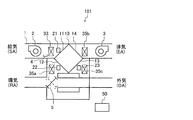
- FIG. 7 is a configuration diagram of the air-conditioning apparatus 101 according to Embodiment 2.
- FIG. 8 is a refrigerant circuit diagram of the air-conditioning apparatus 101 according to Embodiment 2.
- a second intake-side heat exchanger 35c is added to the air conditioner 100 according to Embodiment 1.
- the second intake heat exchanger 35c is provided on the upstream side of the air supply side inlet 13 of the total heat exchanger 10.
- outside air (OA) flows into the supply-side inlet 13 in the case of the outside air intake path
- air (RA) flows in the case of the inside air circulation path.
- the air conditioner 101 includes a refrigerant circuit 201 in which a refrigerant circulates.
- the refrigerant circuit 201 is different from the refrigerant circuit 200 according to Embodiment 1 in that an air supply-side expansion device 34d, a second intake-side heat exchanger 35c, and a second intake-side expansion device 34c are added. .
- the refrigerant circuit 201 includes a compressor 31, a flow path switching device 32, an air supply side heat exchanger 33, an air supply side expansion device 34d, a first intake side expansion device 34a, and a first intake side heat exchanger 35a.
- An exhaust-side expansion device 34b and an exhaust-side heat exchanger 35b which are sequentially connected by piping and connected in series, are parallel to the first intake-side expansion device 34a and the first intake-side heat exchanger 35a.
- the second intake-side heat exchanger 35c and the second intake-side expansion device 34c which are connected to the piping and connected in series, are connected to the supply-side expansion device 34d and the first intake-side expansion device 34a. And are connected in parallel by piping.
- the controller 50 controls the air supply-side expansion device 34d and the second intake-side expansion device 34c, so that the heat exchange between the air supply-side heat exchanger 33 and the second intake-side heat exchanger 35c is required. In addition, the refrigerant is allowed to flow through one or both of them, and the flow rate is adjusted.
- the second intake-side heat exchanger 35c is provided on the upstream side of the supply-side inlet 13 of the total heat exchanger 10, and is configured by the outside air (OA) or the air (RA) taken into the casing 1 and the refrigerant. Heat is exchanged, and the temperature and humidity of the air flowing into the air supply side inlet 13 of the total heat exchanger 10 are adjusted.
- the second intake-side heat exchanger 35c promotes or suppresses humidity exchange between air flowing out to the air supply side and air flowing out to the exhaust side.
- the air-conditioning apparatus 101 instead of cooling or heating the supply air (SA) with the supply-side heat exchanger 33, cooling or heating with the second intake-side heat exchanger 35c.
- the amount of change in the absolute humidity of the supply air (SA) can be suppressed as compared with the case where cooling or heating is performed by the air supply side heat exchanger 33. Therefore, when the difference between the indoor humidity and the required humidity is small, a small change in humidity can be obtained.
- the control of the air supply side heat exchanger 33 may be a sensible heat load. In such a case, comparing the magnitudes of the sensible heat load and the latent heat load, if the sensible heat load is to be given priority, instead of the air supply side heat exchanger 33, the second intake side heat exchanger Use 35c.
- the air supply (SA) is not directly cooled or heated while the humidity exchange efficiency is adjusted by adjusting the relative humidity difference between the air flowing out to the air supply side and the air flowing out to the exhaust side. In some cases, the sensible heat load can be reduced.
- the supply air (SA) is cooled or heated in the air supply side heat exchanger 33, it is also cooled or heated in the second intake side heat exchanger 35c to promote the dehumidification / humidification ability. Can be.
- Embodiment 3 FIG. Hereinafter, a third embodiment of the present invention will be described. However, description of parts overlapping with the first and second embodiments will be omitted, and the same or corresponding parts as in the first and second embodiments will be denoted by the same reference numerals. .
- the air-conditioning apparatus 102 has a dehumidification mode and a humidification mode, and instead of setting the required humidity by the user, the dehumidification mode or the humidification mode is set.
- FIG. 9 is a diagram showing a control flow of the air-conditioning apparatus 102 according to Embodiment 3.
- Q in FIG. 9 represents a load that can be handled by the total heat exchange in the total heat exchanger 10.
- Steps S3 to S5 and S7 to S9 are the same as those described in the first embodiment, and thus description thereof is omitted.
- Step S21 Control device 50 determines whether or not the user has set the dehumidification mode or the humidification mode (hereinafter, referred to as dehumidification / humidification mode setting). When the control device 50 determines that the user has set the dehumidification / humidification mode, the process proceeds to step S22. On the other hand, when the control device 50 determines that the user has not set the dehumidification / humidification mode, step S21 is repeated.
- Step S22 Control device 50 determines the set mode. If it is determined that the dehumidification mode is set, the process proceeds to step S23, and if it is determined that the humidification mode is set, the process proceeds to step S24.
- Step S23 The control device 50 obtains a latent heat load from a difference between the room humidity and a preset reference humidity, and determines whether the latent heat load is larger than Q.
- the control device 50 determines that the latent heat load is larger than Q, that is, when the latent heat load cannot be handled only by the total heat exchanger 10, the process proceeds to step S3.
- the control device 50 determines that the latent heat load is not larger than Q, that is, when the latent heat load can be handled only by the total heat exchanger 10, the process proceeds to step S4.
- Step S24 The control device 50 obtains a latent heat load from a difference between the room humidity and a preset reference humidity, and determines whether the latent heat load is larger than Q.
- the control device 50 determines that the latent heat load is larger than Q, that is, when the latent heat load cannot be handled only by the total heat exchanger 10, the process proceeds to step S7.
- the control device 50 determines that the latent heat load is not larger than Q, that is, when the latent heat load can be handled only by the total heat exchanger 10, the process proceeds to step S8.
- Embodiment 3 As described above, according to the air-conditioning apparatus 102 according to Embodiment 3, the same effects as in Embodiment 1 can be obtained.
Landscapes
- Engineering & Computer Science (AREA)
- Chemical & Material Sciences (AREA)
- Combustion & Propulsion (AREA)
- Mechanical Engineering (AREA)
- General Engineering & Computer Science (AREA)
- Signal Processing (AREA)
- Physics & Mathematics (AREA)
- Fuzzy Systems (AREA)
- Mathematical Physics (AREA)
- Air Conditioning Control Device (AREA)
Abstract
本発明は、十分な換気量を確保しつつ、室内外の温湿度差による室内環境の変動を抑制することができる空気調和装置を提供することを目的としている。 空気調和装置は、ケーシングと、ケーシング内に取り込まれた外気と環気との熱交換を行う全熱交換器と、ケーシング内に外気または環気を取り込み、全熱交換器で全熱交換後、給気として室内に供給する第一送風機と、ケーシング内に外気または環気を取り込み、全熱交換器で全熱交換後、排気として室外に排出する第二送風機と、ケーシング内に取り込まれた外気および環気の流出先を給気側と排気側とに切り替える風路切替手段と、を備えたものである。
Description
本発明は、全熱交換器を備えた空気調和装置に関するものである。
従来、全熱交換器を備えた空気調和装置において、給気(SA)側に熱交換器を配置して、室内機としての機能を付加したものがある(例えば、特許文献1参照)。
特許文献1は、外気(OA)を室内に取り込むが、室内外の温湿度差が大きい場合に全熱交換すると、室内環境が大きく変動してしまうという課題があった。また、室内環境が大きく変動してしまうのを避けるため、室内に取り込む外気(OA)の量を減らすと、十分に換気ができないという課題があった。
本発明は、以上のような課題を解決するためになされたもので、十分な換気量を確保しつつ、室内外の温湿度差による室内環境の変動を抑制することができる空気調和装置を提供することを目的としている。
本発明に係る空気調和装置は、ケーシングと、前記ケーシング内に取り込まれた外気と環気との熱交換を行う全熱交換器と、前記ケーシング内に外気または環気を取り込み、前記全熱交換器で全熱交換後、給気として室内に供給する第一送風機と、前記ケーシング内に外気または環気を取り込み、前記全熱交換器で全熱交換後、排気として室外に排出する第二送風機と、前記ケーシング内に取り込まれた外気および環気の流出先を給気側と排気側とに切り替える風路切替手段と、を備えたものである。
本発明に係る空気調和装置によれば、風路切替手段により、ケーシング内に取り込まれた外気および環気の流出先を給気側と排気側とに切り替えることができるため、必要以上の換気を行わないようにすることで、十分な換気量を確保しつつ、室内外の温湿度差による室内環境の変動を抑制することができる。
以下、本発明の実施の形態を図面に基づいて説明する。なお、以下に説明する実施の形態によって本発明が限定されるものではない。また、以下の図面では各構成部材の大きさの関係が実際のものとは異なる場合がある。
実施の形態1.
図1は、本実施の形態1に係る空気調和装置100の構成図である。
本実施の形態1に係る空気調和装置100は、図1に示すように、箱体形状のケーシング1を備えている。
図1は、本実施の形態1に係る空気調和装置100の構成図である。
本実施の形態1に係る空気調和装置100は、図1に示すように、箱体形状のケーシング1を備えている。
ケーシング1内には、全熱交換器10と、第一送風機2と、第二送風機3と、給気側熱交換器33と、第一取込側熱交換器35aと、排気側熱交換器35bと、ドレンパン4と、風路切替手段5と、給気側温湿度センサ21と、第一取込側温湿度センサ22と、第二取込側温湿度センサ23と、が設けられている。
図2は、本実施の形態1に係る空気調和装置100の流路切替装置32が第一切替状態の冷媒回路図である。図3は、本実施の形態1に係る空気調和装置100の流路切替装置32が第二切替状態の冷媒回路図である。
また、空気調和装置100は、図2および図3に示すように、冷媒が循環する冷媒回路200を備えている。冷媒回路200は、圧縮機31、流路切替装置32、給気側熱交換器33、第一取込側絞り装置34a、第一取込側熱交換器35aが、順次配管で接続され、さらに、直列に配管接続された排気側絞り装置34bおよび排気側熱交換器35bが、第一取込側絞り装置34aおよび第一取込側熱交換器35aに対して並列に配管接続されることにより、構成されている。
また、空気調和装置100は、図2および図3に示すように、冷媒が循環する冷媒回路200を備えている。冷媒回路200は、圧縮機31、流路切替装置32、給気側熱交換器33、第一取込側絞り装置34a、第一取込側熱交換器35aが、順次配管で接続され、さらに、直列に配管接続された排気側絞り装置34bおよび排気側熱交換器35bが、第一取込側絞り装置34aおよび第一取込側熱交換器35aに対して並列に配管接続されることにより、構成されている。
全熱交換器10は、給気側出口11、排気側出口14、給気側入口13、排気側入口12を有し、給気側入口13から給気側出口11に流れる空気(以下、給気側に流出する空気と称する)と、排気側入口12から排気側出口14に流れる空気(以下、排気側に流出する空気と称する)とで熱交換させるものである。なお、給気側に流出する空気および排気側に流出する空気は、一方が外気(OA)で他方が環気(RA)であるが、後述する風路切替手段5の向きによって変わる。
第一送風機2は、外気(OA)または環気(RA)をケーシング1内に取り込んで、全熱交換器10で全熱交換後、給気(SA)として空調対象空間である室内に供給するものである。第二送風機3は、外気(OA)または環気(RA)をケーシング1内に取り込んで、全熱交換器10で全熱交換後、排気(EA)として室外に排出するものである。
なお、本実施の形態では、第一送風機2が給気側出口11の下流側に配置され、第二送風機3が排気側出口14の下流側に配置されているが、それに限定されない。例えば、第一送風機2が給気側入口13の上流側かつ風路切替手段5の下流側に配置され、第二送風機3が排気側入口12の上流側かつ風路切替手段5の下流側に配置されていてもよい。
または、第一送風機2および第二送風機3のうち、いずれか一方が風路切替手段5の上流側かつ環気(RA)取り込み側に配置され、もう一方が風路切替手段5の上流側かつ外気(OA)取り込み側に配置されていてもよい。その場合、風路切替手段5の上流側かつ環気(RA)取り込み側に配置された第一送風機2または第二送風機3は、環気(RA)をケーシング1内に取り込んで、全熱交換器10で全熱交換後、給気(SA)として空調対象空間である室内に供給、または、排気(EA)として室外に排出するものである。一方、風路切替手段5の上流側かつ外気(OA)取り込み側に配置された第一送風機2または第二送風機3は、外気(OA)をケーシング1内に取り込んで、全熱交換器10で全熱交換後、給気(SA)として空調対象空間である室内に供給、または、排気(EA)として室外に排出するものである。
給気側熱交換器33は、全熱交換器10の給気側出口11の下流側に設けられ、全熱交換器10の給気側出口11から流出した空気と冷媒とで熱交換させ、給気(SA)の温湿度を調整するものである。この給気側熱交換器33は、給気(SA)の除加湿に直接的に働きかける。
第一取込側熱交換器35aは、全熱交換器10の排気側入口12の上流側に設けられ、ケーシング1内に取り込まれた外気(OA)または環気(RA)と冷媒とで熱交換させ、全熱交換器10の排気側入口12に流入する空気の温湿度を調整するものである。この第一取込側熱交換器35aは、給気側に流出する空気と排気側に流出する空気との湿度交換を促進または抑制する。
排気側熱交換器35bは、全熱交換器10の排気側出口14の下流側に設けられ、全熱交換器10の排気側出口14から流出した空気と冷媒とで熱交換させ、排気(EA)の温湿度を調整するものである。この排気側熱交換器35bは、第一取込側熱交換器35aでの給気側に流出する空気と排気側に流出する空気との相対湿度差の調整が必要ない場合に第一取込側熱交換器35aの代わりに使用され、余剰な熱を廃棄する、または、無給水加湿を実現するために結露水を発生させるものである。
ドレンパン4は、給気側熱交換器33の近くに配置され、給気側熱交換器33で発生した結露水を、ドレンホース(図示せず)などを介して回収するものである。
給気側温湿度センサ21は、全熱交換器10の給気側出口11の下流側かつ給気側熱交換器33の上流側に設けられ、給気側出口11から流出した空気の温湿度を検知するものである。第一取込側温湿度センサ22は、全熱交換器10の排気側入口12の上流側かつ第一取込側熱交換器35aの下流側に設けられ、排気側入口12に流入する空気の温湿度を検知するものである。第二取込側温湿度センサ23は、全熱交換器10の給気側入口13の上流側に設けられ、給気側入口13に流入する空気の温湿度を検知するものである。
制御装置50は、各温湿度センサが検知した温湿度に基づいて、風路切替手段5、冷媒回路200などを制御するものである。この制御装置50は、例えば、専用のハードウェア、またはメモリに格納されるプログラムを実行するCPU(Central Processing Unit、中央処理装置、処理装置、演算装置、マイクロプロセッサ、マイクロコンピュータ、プロセッサともいう)で構成される。
圧縮機31は、冷媒を吸入し、その冷媒を圧縮して高温高圧の状態にするものであり、例えば周波数が可変できるインバータ圧縮機である。流路切替装置32は、冷媒の流通方向を切り替えるものであり、例えば四方弁である。図2に示すように、流路切替装置32が第一切替状態の場合、給気側熱交換器33が凝縮器として機能し、第一取込側熱交換器35aおよび排気側熱交換器35bが蒸発器として機能する。また、図3に示すように、流路切替装置32が第二切替状態の場合、給気側熱交換器33が蒸発器として機能し、第一取込側熱交換器35aおよび排気側熱交換器35bが凝縮器として機能する。
第一取込側絞り装置34aは、それに流れ込む冷媒を減圧する装置であり、例えば電子膨張弁である。また、第一取込側絞り装置34aは、第一取込側熱交換器35aへの冷媒の流入の有無を開閉により切り替えるものである。排気側絞り装置34bは、それに流れ込む冷媒を減圧する装置であり、例えば電子膨張弁である。また、排気側絞り装置34bは、排気側熱交換器35bへの冷媒の流入の有無を開閉により切り替えるものである。
図4は、本実施の形態1に係る空気調和装置100の風路切替手段5が第一切替状態の構成図である。図5は、本実施の形態1に係る空気調和装置100の風路切替手段5が第二切替状態の構成図である。
風路切替手段5は、外気(OA)および環気(RA)の流出先を給気側と排気側とに切り替えるものであり、例えばダンパ、弁などで構成されている。
風路切替手段5は、外気(OA)および環気(RA)の流出先を給気側と排気側とに切り替えるものであり、例えばダンパ、弁などで構成されている。
図4に示すように、風路切替手段5が第一切替状態の場合、ケーシング1内に外気取込経路が形成され、環気(RA)は、全熱交換器10を通過後、排気側に流れ、外気(OA)は、全熱交換器10を通過後、給気側に流れる。また、図5に示すように、風路切替手段5が第二切替状態の場合、ケーシング1内に内気循環経路が形成され、環気(RA)は、全熱交換器10を通過後、給気側に流れ、外気(OA)は、全熱交換器10を通過後、排気側に流れる。
制御装置50は、例えばガス濃度検知センサーが検知した室内の二酸化炭素などのガス濃度をリアルタイムで監視し、その検知値があらかじめ設定された基準濃度を超えた場合、つまり室内換気が必要な場合は、室内に外気(OA)を取り込むように、風路切替手段5を第一切替方向に切り替え、室外から取り込んだ外気(OA)を給気(SA)として室内に供給して換気を行う。一方、制御装置50は、ガス濃度検知センサーの検知値があらかじめ設定された基準濃度以下である場合、つまり室内換気が不要な場合は、室内を環気(RA)が循環するように、風路切替手段5を第二切替方向に切り替え、室内から取り込んだ環気(RA)を給気(SA)として室内に供給して換気を行う。
また、制御装置50は、例えば室内の床面積などから求めた必要換気量に基づいて、室内の換気量を十分に満たすように、風路切替手段5を外気取込経路と内気循環経路とに時間軸で切り替える。
このように、状況に応じて風路切替手段5を切り替えることで、十分な換気量を確保しつつ、室外の温湿度の影響を受けづらくすることができる。そのため、室内外の温湿度差が大きいときに全熱交換することにより生じる室内環境の変動を抑制することができる。また、内気循環経路となるように風路切替手段5を切り替えても、外気(OA)との全熱交換は可能であるため、要求に応じて換気(RA)と外気(OA)とで熱交換させて、給気(SA)の温湿度を調整することができる。
また、制御装置50は、給気側温湿度センサ21、第一取込側温湿度センサ22、および、第二取込側温湿度センサ23が検知した空気の温湿度を取得する。そして、制御装置50は、環気(RA)と外気(OA)との絶対湿度の差、要求される湿度(除湿または加湿)、要求される給気(SA)の温度(冷房または暖房)などに基づいて、流路切替装置32を切り替える。
制御装置50は、環気(RA)と外気(OA)との絶対湿度の差に基づいて、給気(SA)の除湿が必要であると判定した場合、流路切替装置32を第二切替状態とし、給気側熱交換器33を蒸発器として機能させる。そして、給気(SA)の温度を下げることで、給気側熱交換器33で結露させて給気(SA)を除湿し、その際に発生した結露水をドレンホース(図示せず)などでドレンパン4に回収する。こうすることで、給気(SA)を除湿することができる。なお、排気側熱交換器35bを凝縮器として機能させることで、余剰な熱を廃棄することができる。
また、制御装置50は、環気(RA)と外気(OA)との絶対湿度の差に基づいて、給気(SA)の加湿が必要であると判定した場合、流路切替装置32を第一切替状態とし、給気側熱交換器33を凝縮器として機能させ、第一取込側熱交換器35aまたは排気側熱交換器35bを蒸発器として機能させる。第一取込側熱交換器35aを蒸発器として機能させた場合、環気(RA)または外気(OA)を第一取込側熱交換器35aで冷却して結露水を発生させ、その結露水をドレンホース(図示せず)などでドレンパン4に回収する。一方、排気側熱交換器35bを蒸発器として機能させた場合、排気(EA)を排気側熱交換器35bで冷却して結露水を発生させ、その結露水をドレンホース(図示せず)などでドレンパン4に回収する。
そして、その回収した結露水を含んだ気化フィルタ(図示せず)に、給気側熱交換器33から流出した温かい風を当てて蒸発させ、給気(SA)を加湿する。こうすることで、給気(SA)を無給水加湿することができる。
また、制御装置50は、第一取込側熱交換器35aにより、給気側に流出する空気と排気側に流出する空気との相対湿度差を調整する。こうすることにより、湿度交換を促進または抑制し、室内外の湿度条件に関わらず、ユーザーにより設定された絶対湿度である要求湿度を実現することができる。
また、制御装置50は、「自然除湿」、「自然加湿」、「除湿促進」、および、「加湿促進」の4つのモードを有し、圧縮機31の動作/停止、および、流路切替装置32の切り替えにより、それら4つのモードのうちいずれかを実行する。
「自然除湿」は、室内を除湿するモードの一つであり、給気(SA)の絶対湿度を環気(RA)の絶対湿度よりも下げる必要がある場合、つまり除湿が必要な場合において、室内の潜熱負荷が小さい(または大きくない)場合、かつ、全熱交換器10における除加湿の方向が除湿方向である場合に実行される。ここで、全熱交換器10における除加湿の方向とは、給気側に流出する空気が全熱交換器10での全熱交換で除湿および加湿のどちらが行われるかを意味しており、加湿される場合は加湿方向、除湿される場合は除湿方向である。
「自然加湿」は、室内を加湿するモードの一つであり、給気(SA)の絶対湿度を環気(RA)の絶対湿度よりも上げる必要がある場合、つまり加湿が必要な場合において、室内の潜熱負荷が小さい(または大きくない)場合、かつ、全熱交換器10における除加湿の方向が加湿方向である場合に実行される。
「除湿促進」は、室内を除湿するモードの一つであり、給気(SA)の絶対湿度を環気(RA)の絶対湿度よりも下げる必要がある場合、つまり除湿が必要な場合において、室内の潜熱負荷が大きい場合、または、室内の潜熱負荷が小さくても全熱交換器10における除加湿の方向が加湿方向である場合に実行される。
「加湿促進」は、室内を加湿するモードの一つであり、給気(SA)の絶対湿度を環気(RA)の絶対湿度よりも下げる必要がある場合、つまり加湿が必要な場合において、室内の潜熱負荷が大きい場合、または、室内の潜熱負荷が小さくても全熱交換器10における除加湿の方向が除湿方向である場合に実行される。
なお、「自然除湿」および「自然加湿」では、全熱交換器10での全熱交換のみで湿度調整が可能なため、圧縮機31を停止させる。一方、「除湿促進」および「加湿促進」では、全熱交換器10での全熱交換のみでは湿度調整が不可能なため、圧縮機31を動作させる。また、「除湿促進」では、流路切替装置32を第二切替状態とする。一方、「加湿促進」では、流路切替装置32を第一切替状態とする。なお、必須ではないが、「自然除湿」では、流路切替装置32を第二切替状態としてもよいし、「自然加湿」では、流路切替装置32を第一切替状態としてもよい。
また、4つのモードを実行する際に、風路切替手段5が外気取込経路に切り替えられる場合と、内気循環経路に切り替えられる場合とが考えられるが、上述の通り、室内のガス濃度および必要換気量などの状況に応じて切り替えられる。
図6は、本実施の形態1に係る空気調和装置100の制御フローを示す図である。なお、図6中のQは、全熱交換器10での全熱交換で対応できる負荷を表している。
次に、本実施の形態1に係る空気調和装置100の制御フローについて、図6を用いて説明する。
次に、本実施の形態1に係る空気調和装置100の制御フローについて、図6を用いて説明する。
(ステップS1)
制御装置50は、外気取込経路の場合は第一取込側温湿度センサ22、内気循環経路の場合は第二取込側温湿度センサ23、が検知した環気(RA)の絶対湿度、つまり室内湿度が、要求湿度よりも大きいかどうかを判定する。制御装置50が、室内湿度の方が大きいと判定した場合、ステップS2へ進む。一方、制御装置50が、室内湿度の方が大きくない判定した場合、ステップS6へ進む。
制御装置50は、外気取込経路の場合は第一取込側温湿度センサ22、内気循環経路の場合は第二取込側温湿度センサ23、が検知した環気(RA)の絶対湿度、つまり室内湿度が、要求湿度よりも大きいかどうかを判定する。制御装置50が、室内湿度の方が大きいと判定した場合、ステップS2へ進む。一方、制御装置50が、室内湿度の方が大きくない判定した場合、ステップS6へ進む。
(ステップS2)
制御装置50は、室内湿度と要求湿度との差により求めた潜熱負荷が、Qよりも大きいかどうかを判定する。制御装置50が、潜熱負荷がQよりも大きいと判定した場合、つまり、潜熱負荷が全熱交換器10だけでは対応できない場合、ステップS3へ進む。一方、制御装置50が、潜熱負荷がQよりも大きくないと判定した場合、つまり、潜熱負荷が全熱交換器10だけで対応できる場合、ステップS4へ進む。
制御装置50は、室内湿度と要求湿度との差により求めた潜熱負荷が、Qよりも大きいかどうかを判定する。制御装置50が、潜熱負荷がQよりも大きいと判定した場合、つまり、潜熱負荷が全熱交換器10だけでは対応できない場合、ステップS3へ進む。一方、制御装置50が、潜熱負荷がQよりも大きくないと判定した場合、つまり、潜熱負荷が全熱交換器10だけで対応できる場合、ステップS4へ進む。
(ステップS3)
制御装置50は、「除湿促進」を実行する。制御装置50は、圧縮機31を動作させ、流路切替装置32を第二切替状態とする。そして、給気側熱交換器33が蒸発器として機能することで、給気(SA)の温度が下がって結露水として水分が回収されるため、給気(SA)の絶対湿度を低下させることができる。また、第一取込側熱交換器35aが凝縮器として機能することで、給気側に流出する空気と排気側に流出する空気との相対湿度差を上昇または低下させることができる。つまり、外気(OA)と環気(RA)との相対湿度差を大きくするまたは小さくすることができる。これにより、全熱交換を促進または抑制することができる。ただし、第一取込側熱交換器35aを凝縮器として機能させると、給気(SA)の温度を上昇させる方向に作用するので、蒸発器として機能する給気側熱交換器33側から見ると、負荷が上昇する。そのため、室内外の湿度条件によって第一取込側熱交換器35aでの給気側に流出する空気と排気側に流出する空気との相対湿度差の調整が必要ない場合には、第一取込側熱交換器35aの代わりに排気側熱交換器35bを凝縮器として機能させることで、余剰な熱を廃棄することができる。
制御装置50は、「除湿促進」を実行する。制御装置50は、圧縮機31を動作させ、流路切替装置32を第二切替状態とする。そして、給気側熱交換器33が蒸発器として機能することで、給気(SA)の温度が下がって結露水として水分が回収されるため、給気(SA)の絶対湿度を低下させることができる。また、第一取込側熱交換器35aが凝縮器として機能することで、給気側に流出する空気と排気側に流出する空気との相対湿度差を上昇または低下させることができる。つまり、外気(OA)と環気(RA)との相対湿度差を大きくするまたは小さくすることができる。これにより、全熱交換を促進または抑制することができる。ただし、第一取込側熱交換器35aを凝縮器として機能させると、給気(SA)の温度を上昇させる方向に作用するので、蒸発器として機能する給気側熱交換器33側から見ると、負荷が上昇する。そのため、室内外の湿度条件によって第一取込側熱交換器35aでの給気側に流出する空気と排気側に流出する空気との相対湿度差の調整が必要ない場合には、第一取込側熱交換器35aの代わりに排気側熱交換器35bを凝縮器として機能させることで、余剰な熱を廃棄することができる。
(ステップS4)
制御装置50は、第一取込側温湿度センサ22および第二取込側温湿度センサ23が検知した環気(RA)および外気(OA)の絶対湿度から、全熱交換器10における除加湿の方向が除湿方向であるかどうかを判定する。制御装置50が、全熱交換器10における除加湿の方向が除湿方向であると判定した場合、ステップS5へ進む。一方、制御装置50が、全熱交換器10における除加湿の方向が除湿方向ではない、つまり加湿方向であると判定した場合、ステップS3へ進む。
制御装置50は、第一取込側温湿度センサ22および第二取込側温湿度センサ23が検知した環気(RA)および外気(OA)の絶対湿度から、全熱交換器10における除加湿の方向が除湿方向であるかどうかを判定する。制御装置50が、全熱交換器10における除加湿の方向が除湿方向であると判定した場合、ステップS5へ進む。一方、制御装置50が、全熱交換器10における除加湿の方向が除湿方向ではない、つまり加湿方向であると判定した場合、ステップS3へ進む。
ここで、空気中の水分は、絶対湿度の高い方から低い方へと移動する。このため、外気取込経路の場合において、外気(OA)の絶対湿度AHoa<環気(RA)の絶対湿度AHraの時は、給気側に流出する空気の全熱交換による湿度変化は加湿方向となる。つまり、全熱交換器10における除加湿の方向は加湿方向である。逆に、外気(OA)の絶対湿度AHoa>環気(RA)の絶対湿度AHraの時は、給気側に流出する空気の全熱交換による湿度変化は除湿方向となる。つまり、全熱交換器10における除加湿の方向は除湿方向である。一方、内気循環経路の場合において、外気(OA)の絶対湿度AHoa<環気(RA)の絶対湿度AHraの時は、給気側に流出する空気の全熱交換による湿度変化は除湿方向となる。つまり、全熱交換器10における除加湿の方向は除湿方向である。逆に、外気(OA)の絶対湿度AHoa>環気(RA)の絶対湿度AHraの時は、給気側に流出する空気の全熱交換による湿度変化は加湿方向となる。つまり、全熱交換器10における除加湿の方向は加湿方向である。
(ステップS5)
制御装置50は、「自然除湿」を実行する。制御装置50は、圧縮機31を停止させる。
制御装置50は、「自然除湿」を実行する。制御装置50は、圧縮機31を停止させる。
(ステップS6)
制御装置50は、室内湿度と要求湿度との差により求めた潜熱負荷が、Qよりも大きいかどうかを判定する。制御装置50が、潜熱負荷がQよりも大きいと判定した場合、つまり、潜熱負荷が全熱交換器10だけでは対応できない場合、ステップS7へ進む。一方、制御装置50が、潜熱負荷がQよりも大きくないと判定した場合、つまり、潜熱負荷が全熱交換器10だけで対応できる場合、ステップS8へ進む。
制御装置50は、室内湿度と要求湿度との差により求めた潜熱負荷が、Qよりも大きいかどうかを判定する。制御装置50が、潜熱負荷がQよりも大きいと判定した場合、つまり、潜熱負荷が全熱交換器10だけでは対応できない場合、ステップS7へ進む。一方、制御装置50が、潜熱負荷がQよりも大きくないと判定した場合、つまり、潜熱負荷が全熱交換器10だけで対応できる場合、ステップS8へ進む。
(ステップS7)
制御装置50は、「加湿促進」を実行する。制御装置50は、圧縮機31を動作させ、流路切替装置32を第一切替状態とする。そして、第一取込側熱交換器35aが蒸発器として機能することで、第一取込側熱交換器35aで外気(OA)または環気(RA)を冷却することにより発生した結露水をドレンパン4に回収する。そして、その回収した結露水を含んだ気化フィルタ(図示せず)に、給気側熱交換器33から流出した温かい風を当てて蒸発させることで、給気(SA)の絶対湿度を上昇させることができる。また、第一取込側熱交換器35aが蒸発器として機能することで、給気側に流出する空気と排気側に流出する空気との相対湿度差を上昇または低下させることができる。つまり、外気(OA)と環気(RA)との相対湿度差を大きくするまたは小さくすることができる。これにより、全熱交換を促進または抑制することができる。ただし、第一取込側熱交換器35aを蒸発器として機能させると、給気(SA)の温度を低下させる方向に作用するので、凝縮器として機能する給気側熱交換器33側から見ると、負荷が上昇する。そのため、室内外の湿度条件によって第一取込側熱交換器35aでの給気側に流出する空気と排気側に流出する空気との相対湿度差の調整が必要ない場合には、第一取込側熱交換器35aの代わりに排気側熱交換器35bを蒸発器として機能させ、結露させて発生した結露水をドレンパン4に回収することで、無給水加湿を実現することができる。
制御装置50は、「加湿促進」を実行する。制御装置50は、圧縮機31を動作させ、流路切替装置32を第一切替状態とする。そして、第一取込側熱交換器35aが蒸発器として機能することで、第一取込側熱交換器35aで外気(OA)または環気(RA)を冷却することにより発生した結露水をドレンパン4に回収する。そして、その回収した結露水を含んだ気化フィルタ(図示せず)に、給気側熱交換器33から流出した温かい風を当てて蒸発させることで、給気(SA)の絶対湿度を上昇させることができる。また、第一取込側熱交換器35aが蒸発器として機能することで、給気側に流出する空気と排気側に流出する空気との相対湿度差を上昇または低下させることができる。つまり、外気(OA)と環気(RA)との相対湿度差を大きくするまたは小さくすることができる。これにより、全熱交換を促進または抑制することができる。ただし、第一取込側熱交換器35aを蒸発器として機能させると、給気(SA)の温度を低下させる方向に作用するので、凝縮器として機能する給気側熱交換器33側から見ると、負荷が上昇する。そのため、室内外の湿度条件によって第一取込側熱交換器35aでの給気側に流出する空気と排気側に流出する空気との相対湿度差の調整が必要ない場合には、第一取込側熱交換器35aの代わりに排気側熱交換器35bを蒸発器として機能させ、結露させて発生した結露水をドレンパン4に回収することで、無給水加湿を実現することができる。
(ステップS8)
制御装置50は、第一取込側温湿度センサ22および第二取込側温湿度センサ23が検知した環気(RA)および外気(OA)の絶対湿度から、全熱交換器10における除加湿の方向が加湿方向であるかどうかを判定する。制御装置50が、全熱交換器10における除加湿の方向が加湿方向であると判定した場合、ステップS9へ進む。一方、制御装置50が、全熱交換器10における除加湿の方向が加湿方向ではない、つまり除湿方向であると判定した場合、ステップS7へ進む。
制御装置50は、第一取込側温湿度センサ22および第二取込側温湿度センサ23が検知した環気(RA)および外気(OA)の絶対湿度から、全熱交換器10における除加湿の方向が加湿方向であるかどうかを判定する。制御装置50が、全熱交換器10における除加湿の方向が加湿方向であると判定した場合、ステップS9へ進む。一方、制御装置50が、全熱交換器10における除加湿の方向が加湿方向ではない、つまり除湿方向であると判定した場合、ステップS7へ進む。
(ステップS9)
制御装置50は、「自然加湿」を実行する。制御装置50は、圧縮機31を停止させ、流路切替装置32を第一切替状態とする。
制御装置50は、「自然加湿」を実行する。制御装置50は、圧縮機31を停止させ、流路切替装置32を第一切替状態とする。
従来、室内外の湿度条件によっては、全熱交換することで給気(SA)の絶対湿度がユーザーの除加湿要求とアンマッチになる場合があった。しかし、本実施の形態1では、あえて湿度交換効率を低下させる制御を行うなど、上記のように空気調和装置100を制御することで、室内外の湿度条件に関わらずユーザーの要求にあった空調を行うことができる。また、本実施の形態1に係る空気調和装置100では、室内外の湿度条件および潜熱負荷によって実行するモードを選択することで、ユーザーの除加湿要求を満たしつつ、省エネ運転を行うことができる。また、第一取込側熱交換器35aおよび排気側熱交換器35bのうち、どちらで熱交換を行うか切り替えることができるため、給気側に流出する空気と排気側に流出する空気との相対湿度差の調整の有無を選択して、より効率的な制御を実行することができる。
以上、本実施の形態1に係る空気調和装置100は、ケーシング1と、ケーシング1内に取り込まれた外気(OA)と環気(RA)との熱交換を行う全熱交換器10と、ケーシング1内に外気(OA)または環気(RA)を取り込み、全熱交換器10で全熱交換後、給気(SA)として室内に供給する第一送風機2と、ケーシング1内に外気(OA)または環気(RA)を取り込み、全熱交換器10で全熱交換後、排気(EA)として室外に排出する第二送風機3と、ケーシング1内に取り込まれた外気(OA)および環気(RA)の流出先を給気側と排気側とに切り替える風路切替手段5と、を備えたものである。
本実施の形態1に係る空気調和装置100によれば、風路切替手段5により、ケーシング1内に取り込まれた外気(OA)および環気(RA)の流出先を給気側と排気側とに切り替えることができるため、必要以上の換気を行わないようにすることで、十分な換気量を確保しつつ、室内外の温湿度差による室内環境の変動を抑制することができる。
実施の形態2.
以下、本発明の実施の形態2について説明するが、実施の形態1と重複するものについては説明を省略し、実施の形態1と同じ部分または相当する部分には同じ符号を付す。
以下、本発明の実施の形態2について説明するが、実施の形態1と重複するものについては説明を省略し、実施の形態1と同じ部分または相当する部分には同じ符号を付す。
図7は、本実施の形態2に係る空気調和装置101の構成図である。図8は、本実施の形態2に係る空気調和装置101の冷媒回路図である。
本実施の形態2に係る空気調和装置101では、実施の形態1に係る空気調和装置100に対して、第二取込側熱交換器35cが追加されている。第二取込側熱交換器35cは、全熱交換器10の給気側入口13の上流側に設けられている。なお、給気側入口13には、外気取込経路の場合は外気(OA)が流入し、内気循環経路の場合は環気(RA)が流入する。
本実施の形態2に係る空気調和装置101では、実施の形態1に係る空気調和装置100に対して、第二取込側熱交換器35cが追加されている。第二取込側熱交換器35cは、全熱交換器10の給気側入口13の上流側に設けられている。なお、給気側入口13には、外気取込経路の場合は外気(OA)が流入し、内気循環経路の場合は環気(RA)が流入する。
また、空気調和装置101は、図8に示すように、冷媒が循環する冷媒回路201を備えている。冷媒回路201は、実施の形態1に係る冷媒回路200に対して、給気側絞り装置34d、第二取込側熱交換器35c、および、第二取込側絞り装置34cが追加されている。
冷媒回路201は、圧縮機31、流路切替装置32、給気側熱交換器33、給気側絞り装置34d、第一取込側絞り装置34a、第一取込側熱交換器35aが、順次配管で接続され、さらに、直列に配管接続された排気側絞り装置34bおよび排気側熱交換器35bが、第一取込側絞り装置34aおよび第一取込側熱交換器35aに対して並列に配管接続されるとともに、直列に配管接続された第二取込側熱交換器35cおよび第二取込側絞り装置34cが、給気側絞り装置34dおよび第一取込側絞り装置34aに対して並列に配管接続されることにより、構成されている。
制御装置50は、給気側絞り装置34dおよび第二取込側絞り装置34cを制御することで、給気側熱交換器33および第二取込側熱交換器35cのうち、熱交換が必要などちらか一方あるいは両方に冷媒を流すとともに、その流す流量を調整する。第二取込側熱交換器35cは、全熱交換器10の給気側入口13の上流側に設けられ、ケーシング1内に取り込まれた外気(OA)または環気(RA)と冷媒とで熱交換させ、全熱交換器10の給気側入口13に流入する空気の温湿度を調整するものである。この第二取込側熱交換器35cは、給気側に流出する空気と排気側に流出する空気との湿度交換を促進または抑制する。
本実施の形態2に係る空気調和装置101では、給気(SA)を、給気側熱交換器33で冷却または加熱する代わりに、第二取込側熱交換器35cで冷却または加熱することで、給気側熱交換器33で冷却または加熱するよりも給気(SA)の絶対湿度の変化量を抑えることができる。そのため、室内湿度と要求湿度との差が小さいときなどは、微少な湿度変化とすることができる。また、冷房または暖房の顕熱要求によっては、給気側熱交換器33の制御が顕熱負荷となる場合がある。このような場合において、顕熱負荷と潜熱負荷との大きさを比較して、顕熱負荷の方を優先すべき場合は、給気側熱交換器33ではなく第二取込側熱交換器35cを使用する。
そうすることで、給気側に流出する空気と排気側に流出する空気との相対湿度差の調整により湿度交換効率を調整しつつも、給気(SA)を直接的に冷却または加熱しないため、顕熱負荷を軽減できる場合がある。また、給気(SA)を、給気側熱交換器33で冷却または加熱する際に、合わせて第二取込側熱交換器35cで冷却または加熱することで、除加湿能力を促進することができる。
実施の形態3.
以下、本発明の実施の形態3について説明するが、実施の形態1および2と重複するものについては説明を省略し、実施の形態1および2と同じ部分または相当する部分には同じ符号を付す。
以下、本発明の実施の形態3について説明するが、実施の形態1および2と重複するものについては説明を省略し、実施の形態1および2と同じ部分または相当する部分には同じ符号を付す。
本実施の形態3に係る空気調和装置102では、除湿モードおよび加湿モードを備え、ユーザーにより要求湿度が設定される代わりに、除湿モードまたは加湿モードが設定される。
図9は、本実施の形態3に係る空気調和装置102の制御フローを示す図である。なお、図9中のQは、全熱交換器10での全熱交換で対応できる負荷を表している。
以下、本実施の形態3に係る空気調和装置102の制御フローについて、図9を用いて説明する。なお、ステップS3~S5、S7~S9については、実施の形態1で説明した内容と同じであるため、説明を省略する。
以下、本実施の形態3に係る空気調和装置102の制御フローについて、図9を用いて説明する。なお、ステップS3~S5、S7~S9については、実施の形態1で説明した内容と同じであるため、説明を省略する。
(ステップS21)
制御装置50は、ユーザーにより除湿モードまたは加湿モードの設定(以下、除加湿モード設定と称する)がされているかどうかを判定する。制御装置50が、ユーザーにより除加湿モードの設定がされていると判定した場合、ステップS22へ進む。一方、制御装置50が、ユーザーにより除加湿モードの設定がされていないと判定した場合、ステップS21を繰り返す。
制御装置50は、ユーザーにより除湿モードまたは加湿モードの設定(以下、除加湿モード設定と称する)がされているかどうかを判定する。制御装置50が、ユーザーにより除加湿モードの設定がされていると判定した場合、ステップS22へ進む。一方、制御装置50が、ユーザーにより除加湿モードの設定がされていないと判定した場合、ステップS21を繰り返す。
(ステップS22)
制御装置50は、設定されているモードを判定し、除湿モードが設定されていると判定した場合はステップS23へ進み、加湿モードが設定されていると判定した場合はステップS24へ進む。
制御装置50は、設定されているモードを判定し、除湿モードが設定されていると判定した場合はステップS23へ進み、加湿モードが設定されていると判定した場合はステップS24へ進む。
(ステップS23)
制御装置50は、室内湿度とあらかじめ設定された基準湿度との差により潜熱負荷を求め、その潜熱負荷がQよりも大きいかどうかを判定する。制御装置50が、潜熱負荷がQよりも大きいと判定した場合、つまり、潜熱負荷が全熱交換器10だけでは対応できない場合、ステップS3へ進む。一方、制御装置50が、潜熱負荷がQよりも大きくないと判定した場合、つまり、潜熱負荷が全熱交換器10だけで対応できる場合、ステップS4へ進む。
制御装置50は、室内湿度とあらかじめ設定された基準湿度との差により潜熱負荷を求め、その潜熱負荷がQよりも大きいかどうかを判定する。制御装置50が、潜熱負荷がQよりも大きいと判定した場合、つまり、潜熱負荷が全熱交換器10だけでは対応できない場合、ステップS3へ進む。一方、制御装置50が、潜熱負荷がQよりも大きくないと判定した場合、つまり、潜熱負荷が全熱交換器10だけで対応できる場合、ステップS4へ進む。
(ステップS24)
制御装置50は、室内湿度とあらかじめ設定された基準湿度との差により潜熱負荷を求め、その潜熱負荷がQよりも大きいかどうかを判定する。制御装置50が、潜熱負荷がQよりも大きいと判定した場合、つまり、潜熱負荷が全熱交換器10だけでは対応できない場合、ステップS7へ進む。一方、制御装置50が、潜熱負荷がQよりも大きくないと判定した場合、つまり、潜熱負荷が全熱交換器10だけで対応できる場合、ステップS8へ進む。
制御装置50は、室内湿度とあらかじめ設定された基準湿度との差により潜熱負荷を求め、その潜熱負荷がQよりも大きいかどうかを判定する。制御装置50が、潜熱負荷がQよりも大きいと判定した場合、つまり、潜熱負荷が全熱交換器10だけでは対応できない場合、ステップS7へ進む。一方、制御装置50が、潜熱負荷がQよりも大きくないと判定した場合、つまり、潜熱負荷が全熱交換器10だけで対応できる場合、ステップS8へ進む。
以上、本実施の形態3に係る空気調和装置102によれば、実施の形態1と同じ効果が得られる。
1 ケーシング、2 第一送風機、3 第二送風機、4 ドレンパン、5 風路切替手段、10 全熱交換器、11 給気側出口、12 排気側入口、13 給気側入口、14 排気側出口、21 給気側温湿度センサ、22 第一取込側温湿度センサ、23 第二取込側温湿度センサ、31 圧縮機、32 流路切替装置、33 給気側熱交換器、34a 第一取込側絞り装置、34b 排気側絞り装置、34c 第二取込側絞り装置、34d 給気側絞り装置、35a 第一取込側熱交換器、35b 排気側熱交換器、35c 第二取込側熱交換器、50 制御装置、100 空気調和装置、101 空気調和装置、102 空気調和装置、200 冷媒回路、201 冷媒回路。
Claims (13)
- ケーシングと、
前記ケーシング内に取り込まれた外気と環気との熱交換を行う全熱交換器と、
前記ケーシング内に外気または環気を取り込み、前記全熱交換器で全熱交換後、給気として室内に供給する第一送風機と、
前記ケーシング内に外気または環気を取り込み、前記全熱交換器で全熱交換後、排気として室外に排出する第二送風機と、
前記ケーシング内に取り込まれた外気および環気の流出先を給気側と排気側とに切り替える風路切替手段と、を備えた
空気調和装置。 - 前記全熱交換器から流出した空気と冷媒との熱交換を行い、前記給気の温湿度を調整する給気側熱交換器と、
前記全熱交換器から流出した空気と冷媒との熱交換を行い、前記排気の温湿度を調整する排気側熱交換器と、
前記ケーシング内に取り込まれた前記外気または前記環気と冷媒との熱交換を行い、前記全熱交換器の排気側入口に流入する空気の温湿度を調整する第一取込側熱交換器と、を備えた
請求項1に記載の空気調和装置。 - 圧縮機、流路切替装置、前記給気側熱交換器、第一取込側絞り装置、前記第一取込側熱交換器が、順次配管で接続され、さらに、直列に配管接続された排気側絞り装置および前記排気側熱交換器が、前記第一取込側絞り装置および前記第一取込側熱交換器に対して並列に配管接続された冷媒回路を備えた
請求項2に記載の空気調和装置。 - 前記ケーシング内に取り込まれた前記外気または前記環気と冷媒との熱交換を行い、前記全熱交換器の給気側入口に流入する空気の温湿度を調整する第二取込側熱交換器と、
圧縮機、流路切替装置、前記給気側熱交換器、給気側絞り装置、第一取込側絞り装置、前記第一取込側熱交換器が、順次配管で接続され、さらに、直列に配管接続された排気側絞り装置および前記排気側熱交換器が、前記第一取込側絞り装置および前記第一取込側熱交換器に対して並列に配管接続されるとともに、直列に配管接続された前記第二取込側熱交換器および第二取込側絞り装置が、前記給気側絞り装置および前記給気側絞り装置に対して並列に配管接続された冷媒回路と、を備えた
請求項2に記載の空気調和装置。 - 前記圧縮機および前記流路切替装置を制御する
制御装置を備えた
請求項3または4に記載の空気調和装置。 - 前記制御装置は、
室内湿度が要求湿度よりも大きいかどうかを判定し、前記室内湿度が前記要求湿度よりも大きいと判定した場合、または、除湿モードが設定されている場合は、
潜熱負荷が前記全熱交換器で対応できる負荷よりも大きいかどうかを判定し、
前記潜熱負荷が前記全熱交換器で対応できる負荷よりも大きいと判定した場合は、
前記圧縮機を動作させ、前記流路切替装置を前記給気側熱交換器が蒸発器として機能するように切り替える
請求項5に記載の空気調和装置。 - 前記制御装置は、
室内湿度が要求湿度よりも大きいかどうかを判定し、前記室内湿度が前記要求湿度よりも大きいと判定した場合、または、除湿モードが設定されている場合は、
潜熱負荷が前記全熱交換器で対応できる負荷よりも大きいかどうかを判定し、
前記潜熱負荷が前記全熱交換器で対応できる負荷よりも大きくないと判定した場合は、
給気側に流出する空気が前記全熱交換器での全熱交換で除湿されるかどうかを判定する
請求項5または6に記載の空気調和装置。 - 前記制御装置は、
給気側に流出する空気が前記全熱交換器での全熱交換で除湿されると判定した場合は、前記圧縮機を停止させる
請求項7に記載の空気調和装置。 - 前記制御装置は、
給気側に流出する空気が前記全熱交換器での全熱交換で除湿されないと判定した場合は、前記圧縮機を動作させ、前記流路切替装置を前記給気側熱交換器が蒸発器として機能するように切り替える
請求項7または8に記載の空気調和装置。 - 前記制御装置は、
室内湿度が要求湿度よりも大きいかどうかを判定し、前記室内湿度が前記要求湿度よりも大きくないと判定した場合、または、加湿モードが設定されている場合は、
潜熱負荷が前記全熱交換器で対応できる負荷よりも大きいかどうかを判定し、
前記潜熱負荷が前記全熱交換器で対応できる負荷よりも大きいと判定した場合は、
前記圧縮機を動作させ、前記流路切替装置を前記給気側熱交換器が凝縮器として機能するように切り替える
請求項5~9のいずれか一項に記載の空気調和装置。 - 前記制御装置は、
室内湿度が要求湿度よりも大きいかどうかを判定し、前記室内湿度が前記要求湿度よりも大きくないと判定した場合、または、加湿モードが設定されている場合は、
潜熱負荷が前記全熱交換器で対応できる負荷よりも大きいかどうかを判定し、
前記潜熱負荷が前記全熱交換器で対応できる負荷よりも大きくないと判定した場合は、
給気側に流出する空気が前記全熱交換器での全熱交換で加湿されるかどうかを判定する
請求項9または10に記載の空気調和装置。 - 前記制御装置は、
給気側に流出する空気が前記全熱交換器での全熱交換で加湿されると判定した場合は、前記圧縮機を停止させる
請求項11に記載の空気調和装置。 - 前記制御装置は、
給気側に流出する空気が前記全熱交換器での全熱交換で加湿されないと判定した場合は、前記圧縮機を動作させ、前記流路切替装置を前記給気側熱交換器が凝縮器として機能するように切り替える
請求項11または12に記載の空気調和装置。
Priority Applications (1)
| Application Number | Priority Date | Filing Date | Title |
|---|---|---|---|
| PCT/JP2018/024632 WO2020003446A1 (ja) | 2018-06-28 | 2018-06-28 | 空気調和装置 |
Applications Claiming Priority (1)
| Application Number | Priority Date | Filing Date | Title |
|---|---|---|---|
| PCT/JP2018/024632 WO2020003446A1 (ja) | 2018-06-28 | 2018-06-28 | 空気調和装置 |
Publications (1)
| Publication Number | Publication Date |
|---|---|
| WO2020003446A1 true WO2020003446A1 (ja) | 2020-01-02 |
Family
ID=68984927
Family Applications (1)
| Application Number | Title | Priority Date | Filing Date |
|---|---|---|---|
| PCT/JP2018/024632 Ceased WO2020003446A1 (ja) | 2018-06-28 | 2018-06-28 | 空気調和装置 |
Country Status (1)
| Country | Link |
|---|---|
| WO (1) | WO2020003446A1 (ja) |
Cited By (6)
| Publication number | Priority date | Publication date | Assignee | Title |
|---|---|---|---|---|
| CN112503732A (zh) * | 2020-11-30 | 2021-03-16 | 珠海格力电器股份有限公司 | 空调机组温湿度控制方法、装置、系统和一种空调机组 |
| JP2021169916A (ja) * | 2020-04-14 | 2021-10-28 | 北京小米移動軟件有限公司Beijing Xiaomi Mobile Software Co., Ltd. | 外気導入空調システム及び吹き出し口の調整方法 |
| WO2021229687A1 (ja) * | 2020-05-12 | 2021-11-18 | 三菱電機株式会社 | 加熱制御装置及び加熱制御プログラム |
| CN114110984A (zh) * | 2021-11-24 | 2022-03-01 | 广东美的制冷设备有限公司 | 新风设备及其控制方法、控制装置、存储介质 |
| JPWO2022085083A1 (ja) * | 2020-10-20 | 2022-04-28 | ||
| WO2023149369A1 (ja) * | 2022-02-03 | 2023-08-10 | ブラザー工業株式会社 | 空調機 |
Citations (12)
| Publication number | Priority date | Publication date | Assignee | Title |
|---|---|---|---|---|
| JPS4736706B1 (ja) * | 1970-10-08 | 1972-09-14 | ||
| JPS5288444U (ja) * | 1975-12-26 | 1977-07-01 | ||
| JPS55107844A (en) * | 1979-02-13 | 1980-08-19 | Toshiba Corp | Air conditioning device |
| JPH04353327A (ja) * | 1991-05-30 | 1992-12-08 | Hitachi Ltd | 換気機能付空気調和装置 |
| JPH06337151A (ja) * | 1993-05-27 | 1994-12-06 | Sanyo Electric Co Ltd | 空気調和装置 |
| JPH0742990A (ja) * | 1993-07-31 | 1995-02-10 | Ryuichi Kurokawa | 遊技場における空気調和機の省エネルギー制御方法 |
| JP2000220877A (ja) * | 1999-01-29 | 2000-08-08 | Daikin Ind Ltd | 換気空調機 |
| JP2006090572A (ja) * | 2004-09-21 | 2006-04-06 | Sanden Corp | 空気調和機 |
| JP2008215756A (ja) * | 2007-03-07 | 2008-09-18 | Sanyo Electric Co Ltd | 乾燥空気供給装置および乾燥機 |
| JP2009281707A (ja) * | 2008-05-26 | 2009-12-03 | Mitsubishi Electric Corp | 熱回収装置 |
| JP2014153009A (ja) * | 2013-02-12 | 2014-08-25 | Topre Corp | 外気処理装置 |
| JP2017125666A (ja) * | 2016-01-15 | 2017-07-20 | ダイキン工業株式会社 | 冷凍装置および管理システム |
-
2018
- 2018-06-28 WO PCT/JP2018/024632 patent/WO2020003446A1/ja not_active Ceased
Patent Citations (12)
| Publication number | Priority date | Publication date | Assignee | Title |
|---|---|---|---|---|
| JPS4736706B1 (ja) * | 1970-10-08 | 1972-09-14 | ||
| JPS5288444U (ja) * | 1975-12-26 | 1977-07-01 | ||
| JPS55107844A (en) * | 1979-02-13 | 1980-08-19 | Toshiba Corp | Air conditioning device |
| JPH04353327A (ja) * | 1991-05-30 | 1992-12-08 | Hitachi Ltd | 換気機能付空気調和装置 |
| JPH06337151A (ja) * | 1993-05-27 | 1994-12-06 | Sanyo Electric Co Ltd | 空気調和装置 |
| JPH0742990A (ja) * | 1993-07-31 | 1995-02-10 | Ryuichi Kurokawa | 遊技場における空気調和機の省エネルギー制御方法 |
| JP2000220877A (ja) * | 1999-01-29 | 2000-08-08 | Daikin Ind Ltd | 換気空調機 |
| JP2006090572A (ja) * | 2004-09-21 | 2006-04-06 | Sanden Corp | 空気調和機 |
| JP2008215756A (ja) * | 2007-03-07 | 2008-09-18 | Sanyo Electric Co Ltd | 乾燥空気供給装置および乾燥機 |
| JP2009281707A (ja) * | 2008-05-26 | 2009-12-03 | Mitsubishi Electric Corp | 熱回収装置 |
| JP2014153009A (ja) * | 2013-02-12 | 2014-08-25 | Topre Corp | 外気処理装置 |
| JP2017125666A (ja) * | 2016-01-15 | 2017-07-20 | ダイキン工業株式会社 | 冷凍装置および管理システム |
Cited By (12)
| Publication number | Priority date | Publication date | Assignee | Title |
|---|---|---|---|---|
| JP2021169916A (ja) * | 2020-04-14 | 2021-10-28 | 北京小米移動軟件有限公司Beijing Xiaomi Mobile Software Co., Ltd. | 外気導入空調システム及び吹き出し口の調整方法 |
| JP7269205B2 (ja) | 2020-04-14 | 2023-05-08 | 北京小米移動軟件有限公司 | 外気導入空調システム及び吹き出し口の調整方法 |
| WO2021229687A1 (ja) * | 2020-05-12 | 2021-11-18 | 三菱電機株式会社 | 加熱制御装置及び加熱制御プログラム |
| JPWO2021229687A1 (ja) * | 2020-05-12 | 2021-11-18 | ||
| JP7305043B2 (ja) | 2020-05-12 | 2023-07-07 | 三菱電機株式会社 | 加熱制御装置及び加熱制御プログラム |
| JPWO2022085083A1 (ja) * | 2020-10-20 | 2022-04-28 | ||
| WO2022085083A1 (ja) * | 2020-10-20 | 2022-04-28 | 三菱電機株式会社 | 外気調和機 |
| JP7399310B2 (ja) | 2020-10-20 | 2023-12-15 | 三菱電機株式会社 | 外気調和機 |
| CN112503732A (zh) * | 2020-11-30 | 2021-03-16 | 珠海格力电器股份有限公司 | 空调机组温湿度控制方法、装置、系统和一种空调机组 |
| CN112503732B (zh) * | 2020-11-30 | 2022-01-28 | 珠海格力电器股份有限公司 | 空调机组温湿度控制方法、装置、系统和一种空调机组 |
| CN114110984A (zh) * | 2021-11-24 | 2022-03-01 | 广东美的制冷设备有限公司 | 新风设备及其控制方法、控制装置、存储介质 |
| WO2023149369A1 (ja) * | 2022-02-03 | 2023-08-10 | ブラザー工業株式会社 | 空調機 |
Similar Documents
| Publication | Publication Date | Title |
|---|---|---|
| JP5328951B2 (ja) | 空気調和システム | |
| JP6234574B2 (ja) | 換気装置 | |
| WO2020003446A1 (ja) | 空気調和装置 | |
| JP4993014B2 (ja) | コントローラおよび空調処理システム | |
| JP6234575B2 (ja) | 換気装置 | |
| AU2008320209B2 (en) | Humidity control apparatus | |
| WO2012049897A1 (ja) | 空調制御装置 | |
| JPWO2013014708A1 (ja) | 調湿装置、空気調和システム及び調湿装置の制御方法 | |
| JP5229368B2 (ja) | 調湿装置 | |
| CN114110884B (zh) | 新风机及其控制方法、计算机可读存储介质 | |
| JP7026781B2 (ja) | 空気調和システム | |
| JP2011202916A (ja) | 空調制御装置 | |
| WO2020261982A1 (ja) | 空調システム | |
| WO2020053929A1 (ja) | 空気調和装置 | |
| JP5369577B2 (ja) | 空調システム | |
| JP2012088042A (ja) | 空調制御装置 | |
| WO2020261794A1 (ja) | 外気処理装置及び空調システム | |
| JP5594030B2 (ja) | コントローラ、調湿用制御部および空調処理システム | |
| JP6938950B2 (ja) | 空気調和システム | |
| JP2010127522A (ja) | 空調システム | |
| JP7374633B2 (ja) | 空気調和機及び空気調和システム | |
| JP2020012603A (ja) | 空気調和システム | |
| JP5396799B2 (ja) | 調湿システム | |
| JP7189472B2 (ja) | 空調システム | |
| JP5332466B2 (ja) | 調湿システム |
Legal Events
| Date | Code | Title | Description |
|---|---|---|---|
| 121 | Ep: the epo has been informed by wipo that ep was designated in this application |
Ref document number: 18924325 Country of ref document: EP Kind code of ref document: A1 |
|
| NENP | Non-entry into the national phase |
Ref country code: DE |
|
| 122 | Ep: pct application non-entry in european phase |
Ref document number: 18924325 Country of ref document: EP Kind code of ref document: A1 |
|
| NENP | Non-entry into the national phase |
Ref country code: JP |