WO2020003446A1 - Dispositif de climatisation - Google Patents
Dispositif de climatisation Download PDFInfo
- Publication number
- WO2020003446A1 WO2020003446A1 PCT/JP2018/024632 JP2018024632W WO2020003446A1 WO 2020003446 A1 WO2020003446 A1 WO 2020003446A1 JP 2018024632 W JP2018024632 W JP 2018024632W WO 2020003446 A1 WO2020003446 A1 WO 2020003446A1
- Authority
- WO
- WIPO (PCT)
- Prior art keywords
- air
- heat exchanger
- total heat
- humidity
- intake
- Prior art date
Links
Images


Classifications
-
- F—MECHANICAL ENGINEERING; LIGHTING; HEATING; WEAPONS; BLASTING
- F24—HEATING; RANGES; VENTILATING
- F24F—AIR-CONDITIONING; AIR-HUMIDIFICATION; VENTILATION; USE OF AIR CURRENTS FOR SCREENING
- F24F1/00—Room units for air-conditioning, e.g. separate or self-contained units or units receiving primary air from a central station
- F24F1/02—Self-contained room units for air-conditioning, i.e. with all apparatus for treatment installed in a common casing
-
- F—MECHANICAL ENGINEERING; LIGHTING; HEATING; WEAPONS; BLASTING
- F24—HEATING; RANGES; VENTILATING
- F24F—AIR-CONDITIONING; AIR-HUMIDIFICATION; VENTILATION; USE OF AIR CURRENTS FOR SCREENING
- F24F11/00—Control or safety arrangements
- F24F11/62—Control or safety arrangements characterised by the type of control or by internal processing, e.g. using fuzzy logic, adaptive control or estimation of values
- F24F11/63—Electronic processing
- F24F11/65—Electronic processing for selecting an operating mode
-
- F—MECHANICAL ENGINEERING; LIGHTING; HEATING; WEAPONS; BLASTING
- F24—HEATING; RANGES; VENTILATING
- F24F—AIR-CONDITIONING; AIR-HUMIDIFICATION; VENTILATION; USE OF AIR CURRENTS FOR SCREENING
- F24F7/00—Ventilation
- F24F7/04—Ventilation with ducting systems, e.g. by double walls; with natural circulation
- F24F7/06—Ventilation with ducting systems, e.g. by double walls; with natural circulation with forced air circulation, e.g. by fan positioning of a ventilator in or against a conduit
- F24F7/08—Ventilation with ducting systems, e.g. by double walls; with natural circulation with forced air circulation, e.g. by fan positioning of a ventilator in or against a conduit with separate ducts for supplied and exhausted air with provisions for reversal of the input and output systems
Definitions
- the present invention relates to an air conditioner provided with a total heat exchanger.
- Patent Document 1 takes in outside air (OA) into a room, but there is a problem that if total heat exchange is performed when there is a large difference in temperature and humidity between the room and the outside, the room environment fluctuates greatly. In addition, if the amount of outside air (OA) taken into the room is reduced in order to avoid a large fluctuation in the indoor environment, there is a problem that sufficient ventilation cannot be achieved.
- OA outside air
- the present invention has been made to solve the above problems, and provides an air conditioner capable of suppressing a change in the indoor environment due to a difference in temperature and humidity between the inside and outside of a room while securing a sufficient amount of ventilation. It is intended to be.
- the air conditioner according to the present invention includes a casing, a total heat exchanger that exchanges heat between the outside air and the atmosphere taken in the casing, and an outside air or an atmosphere taken into the casing, and the total heat exchange.
- air path switching means for switching the outflow destination of the outside air and the air taken into the casing between an air supply side and an exhaust side.
- the air path switching means can switch the outflow destination of the outside air and the air taken in the casing between the air supply side and the exhaust side, so that more ventilation than necessary is provided. By not performing this, it is possible to suppress a change in the indoor environment due to a difference in temperature and humidity between the inside and outside of the room while securing a sufficient ventilation volume.
- FIG. 2 is a configuration diagram of the air-conditioning apparatus according to Embodiment 1;
- FIG. 3 is a refrigerant circuit diagram of the flow switching device of the air-conditioning apparatus according to Embodiment 1 in a first switching state.
- FIG. 3 is a refrigerant circuit diagram of the flow path switching device of the air-conditioning apparatus according to Embodiment 1 in a second switching state.
- FIG. 3 is a configuration diagram illustrating a first switching state of an air path switching unit of the air-conditioning apparatus according to Embodiment 1.
- FIG. 3 is a configuration diagram of the air path switching unit of the air-conditioning apparatus according to Embodiment 1 in a second switching state.
- FIG. 3 is a diagram showing a control flow of the air-conditioning apparatus according to Embodiment 1.
- FIG. 4 is a configuration diagram of an air-conditioning apparatus according to Embodiment 2;
- FIG. 5 is a refrigerant circuit diagram of the air-conditioning apparatus according to Embodiment 2.
- FIG. 13 is a diagram showing a control flow of the air-conditioning apparatus according to Embodiment 3.
- FIG. FIG. 1 is a configuration diagram of the air-conditioning apparatus 100 according to Embodiment 1.
- the air-conditioning apparatus 100 according to Embodiment 1 includes a box-shaped casing 1 as shown in FIG.
- a drain pan 4 Inside the casing 1, the total heat exchanger 10, the first blower 2, the second blower 3, the air supply side heat exchanger 33, the first intake side heat exchanger 35a, and the exhaust side heat exchanger 35b, a drain pan 4, an air passage switching means 5, an air supply-side temperature and humidity sensor 21, a first intake-side temperature and humidity sensor 22, and a second intake-side temperature and humidity sensor 23 are provided. .
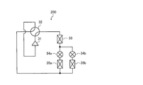
- FIG. 2 is a refrigerant circuit diagram of the air conditioner 100 according to Embodiment 1 in which the flow path switching device 32 is in the first switching state.
- FIG. 3 is a refrigerant circuit diagram of the air conditioner 100 according to Embodiment 1 in which the flow path switching device 32 is in the second switching state.
- the air conditioner 100 includes a refrigerant circuit 200 through which the refrigerant circulates, as shown in FIGS. 2 and 3.
- the compressor 31, the flow path switching device 32, the air supply side heat exchanger 33, the first intake side expansion device 34a, and the first intake side heat exchanger 35a are sequentially connected by pipes.
- the exhaust-side expansion device 34b and the exhaust-side heat exchanger 35b which are connected in series, are connected in parallel with the first intake-side expansion device 34a and the first intake-side heat exchanger 35a. ,It is configured.
- the total heat exchanger 10 has a supply-side outlet 11, an exhaust-side outlet 14, a supply-side inlet 13, and an exhaust-side inlet 12, and air flowing from the supply-side inlet 13 to the supply-side outlet 11 (hereinafter, referred to as supply).
- supply air flowing from the supply-side inlet 13 to the supply-side outlet 11
- air flowing out to the exhaust side air flowing out to the exhaust side
- One of the air flowing out to the air supply side and the air flowing out to the exhaust side is outside air (OA) and the other is air (RA).
- the first blower 2 takes in outside air (OA) or ambient air (RA) into the casing 1, and after performing total heat exchange in the total heat exchanger 10, supplies the air as air supply (SA) to a room that is a space to be air-conditioned. Things.
- the second blower 3 takes in outside air (OA) or ambient air (RA) into the casing 1, and after performing total heat exchange in the total heat exchanger 10, discharges the exhaust air (EA) to the outside of the room.
- the first blower 2 is arranged downstream of the supply-side outlet 11 and the second blower 3 is arranged downstream of the exhaust-side outlet 14.
- the present invention is not limited to this.
- the first blower 2 is disposed on the upstream side of the air supply side inlet 13 and downstream of the air path switching means 5, and the second blower 3 is located upstream of the exhaust side inlet 12 and downstream of the air path switching means 5. It may be arranged.
- one of the first blower 2 and the second blower 3 is arranged on the upstream side of the air path switching means 5 and on the air intake (RA) intake side, and the other is on the upstream side of the air path switching means 5 and It may be arranged on the outside air (OA) intake side.
- the first blower 2 or the second blower 3 arranged on the upstream side of the air path switching means 5 and on the air (RA) intake side takes in the air (RA) into the casing 1 and performs total heat exchange. After the total heat exchange in the vessel 10, the air is supplied to a room which is a space to be air-conditioned as air supply (SA), or is discharged outside as air (EA).
- the first blower 2 or the second blower 3 arranged on the upstream side of the air passage switching means 5 and on the outside air (OA) intake side takes in the outside air (OA) into the casing 1, and After the total heat exchange, the air is supplied as air supply (SA) into a room which is a space to be air-conditioned, or is discharged outside as air (EA).
- SA air supply
- EA discharged outside as air
- the air supply side heat exchanger 33 is provided on the downstream side of the air supply side outlet 11 of the total heat exchanger 10, and causes the air and the refrigerant flowing out of the air supply side outlet 11 of the total heat exchanger 10 to exchange heat with the refrigerant.
- the temperature and humidity of the supply air (SA) are adjusted.
- the air supply side heat exchanger 33 directly acts on dehumidification and humidification of the air supply (SA).
- the first intake-side heat exchanger 35a is provided on the upstream side of the exhaust-side inlet 12 of the total heat exchanger 10, and heats the outside air (OA) or the air (RA) taken into the casing 1 and the refrigerant. The temperature and humidity of the air flowing into the exhaust-side inlet 12 of the total heat exchanger 10 are adjusted. The first intake heat exchanger 35a promotes or suppresses the exchange of humidity between the air flowing out to the air supply side and the air flowing out to the exhaust side.
- the exhaust-side heat exchanger 35b is provided on the downstream side of the exhaust-side outlet 14 of the total heat exchanger 10, and causes the air and the refrigerant flowing out of the exhaust-side outlet 14 of the total heat exchanger 10 to exchange heat with the refrigerant, thereby exhausting (EA). ) To adjust the temperature and humidity.
- the exhaust-side heat exchanger 35b is used when the relative humidity difference between the air flowing out to the air supply side and the air flowing out to the exhaust side in the first intake-side heat exchanger 35a is not necessary. It is used in place of the side heat exchanger 35a, and is used to discard excess heat or generate dew water to realize non-supply water humidification.
- the drain pan 4 is disposed near the air supply side heat exchanger 33, and collects dew water generated in the air supply side heat exchanger 33 via a drain hose (not shown) or the like.
- the supply-side temperature / humidity sensor 21 is provided on the downstream side of the supply-side outlet 11 of the total heat exchanger 10 and on the upstream side of the supply-side heat exchanger 33, and detects the temperature and humidity of the air flowing out of the supply-side outlet 11. Is to be detected.
- the first intake-side temperature / humidity sensor 22 is provided upstream of the exhaust-side inlet 12 of the total heat exchanger 10 and downstream of the first intake-side heat exchanger 35a. It detects temperature and humidity.
- the second intake-side temperature / humidity sensor 23 is provided upstream of the air supply side inlet 13 of the total heat exchanger 10 and detects the temperature and humidity of the air flowing into the air supply side inlet 13.
- the control device 50 controls the air path switching means 5, the refrigerant circuit 200, and the like based on the temperature and humidity detected by each temperature and humidity sensor.
- the control device 50 is, for example, dedicated hardware or a CPU (Central Processing Unit), which executes a program stored in a memory (also referred to as a central processing unit, a processing unit, an arithmetic unit, a microprocessor, a microcomputer, or a processor). Be composed.
- a CPU Central Processing Unit
- the compressor 31 sucks the refrigerant, compresses the refrigerant to a high temperature and high pressure state, and is, for example, an inverter compressor whose frequency can be varied.
- the flow path switching device 32 switches the flow direction of the refrigerant, and is, for example, a four-way valve. As shown in FIG. 2, when the flow path switching device 32 is in the first switching state, the air supply side heat exchanger 33 functions as a condenser, and the first intake side heat exchanger 35a and the exhaust side heat exchanger 35b. Functions as an evaporator. Further, as shown in FIG. 3, when the flow path switching device 32 is in the second switching state, the air supply side heat exchanger 33 functions as an evaporator, and the first intake side heat exchanger 35a and the exhaust side heat exchange The vessel 35b functions as a condenser.
- the first intake-side expansion device 34a is a device for reducing the pressure of the refrigerant flowing into it, and is, for example, an electronic expansion valve.
- the first intake-side expansion device 34a switches the presence or absence of the inflow of the refrigerant into the first intake-side heat exchanger 35a by opening and closing.
- the exhaust-side expansion device 34b is a device that reduces the pressure of the refrigerant flowing into the exhaust-side expansion device 34b, and is, for example, an electronic expansion valve.
- the exhaust-side expansion device 34b switches the presence or absence of the inflow of the refrigerant into the exhaust-side heat exchanger 35b by opening and closing.
- FIG. 4 is a configuration diagram of the air path switching unit 5 of the air-conditioning apparatus 100 according to Embodiment 1 in the first switching state.
- FIG. 5 is a configuration diagram of the air path switching unit 5 of the air-conditioning apparatus 100 according to Embodiment 1 in the second switching state.
- the air path switching means 5 switches the outflow destination of the outside air (OA) and the air (RA) between the supply side and the exhaust side, and is configured by, for example, a damper, a valve, and the like.
- an outside air intake path is formed in the casing 1, and the air (RA) passes through the total heat exchanger 10 and then passes through the exhaust side.
- the outside air (OA) flows through the total heat exchanger 10 and then flows to the air supply side.
- an inside air circulation path is formed in the casing 1, and the air (RA) is supplied after passing through the total heat exchanger 10. After flowing through the total heat exchanger 10, the outside air (OA) flows to the exhaust side.
- the control device 50 monitors, for example, the gas concentration of indoor carbon dioxide and the like detected by the gas concentration detection sensor in real time, and when the detected value exceeds a preset reference concentration, that is, when indoor ventilation is required. Then, the air path switching means 5 is switched to the first switching direction so that outside air (OA) is taken into the room, and the outside air (OA) taken from outside is supplied to the room as air supply (SA) to perform ventilation. On the other hand, when the detection value of the gas concentration detection sensor is equal to or lower than the preset reference concentration, that is, when the indoor ventilation is unnecessary, the control device 50 controls the air path so that the air circulation (RA) circulates in the room. The switching means 5 is switched to the second switching direction, and air (RA) taken in from the room is supplied to the room as air supply (SA) to perform ventilation.
- SA air supply
- control device 50 sets the air passage switching means 5 to an outside air intake path and an inside air circulation path based on a required ventilation amount obtained from, for example, the floor area of the room so as to sufficiently satisfy the ventilation amount in the room. Switch on the time axis.
- the air path switching means 5 by switching the air path switching means 5 according to the situation, it is possible to secure sufficient ventilation and to reduce the influence of outdoor temperature and humidity. For this reason, it is possible to suppress a change in the indoor environment caused by performing total heat exchange when the difference between the temperature and the humidity inside and outside the room is large. Further, even if the air path switching means 5 is switched so as to form an internal air circulation path, since the total heat exchange with the outside air (OA) is possible, the heat is exchanged between the ventilation (RA) and the outside air (OA) as required. The temperature and humidity of the supply air (SA) can be adjusted by replacement.
- the control device 50 acquires the temperature and humidity of the air detected by the supply-side temperature and humidity sensor 21, the first intake-side temperature and humidity sensor 22, and the second intake-side temperature and humidity sensor 23. Then, the controller 50 controls the absolute humidity difference between the air (RA) and the outside air (OA), the required humidity (dehumidification or humidification), the required supply air (SA) temperature (cooling or heating), and the like.
- the flow path switching device 32 is switched based on.
- the control device 50 determines that the supply air (SA) needs to be dehumidified based on the absolute humidity difference between the atmosphere (RA) and the outside air (OA), the control device 50 switches the flow path switching device 32 to the second switching.
- the supply-side heat exchanger 33 functions as an evaporator.
- the air is condensed in the air supply side heat exchanger 33 to dehumidify the air supply (SA), and the condensed water generated at that time is drained by a drain hose (not shown) or the like.
- a drain hose not shown
- the supply air (SA) can be dehumidified.
- excess heat can be discarded.
- the control device 50 determines that the supply air (SA) needs to be humidified based on the difference between the absolute humidity of the air (RA) and the outside air (OA), the control device 50 switches the flow path switching device 32 to the second position.
- the supply-side heat exchanger 33 functions as a condenser
- the first intake-side heat exchanger 35a or the exhaust-side heat exchanger 35b functions as an evaporator.
- the air (RA) or the outside air (OA) is cooled by the first intake-side heat exchanger 35a to generate dew condensation water. Water is collected in a drain pan 4 by a drain hose (not shown) or the like.
- the exhaust-side heat exchanger 35b functions as an evaporator
- the exhaust gas (EA) is cooled by the exhaust-side heat exchanger 35b to generate condensed water, and the condensed water is drained by a drain hose (not shown) or the like.
- a drain hose not shown
- the control device 50 adjusts the relative humidity difference between the air flowing out to the air supply side and the air flowing out to the exhaust side by the first intake side heat exchanger 35a. By doing so, it is possible to promote or suppress the humidity exchange, and to achieve the required humidity, which is the absolute humidity set by the user, regardless of the indoor and outdoor humidity conditions.
- control device 50 has four modes of “natural dehumidification”, “natural humidification”, “dehumidification promotion”, and “humidification promotion”, and operates / stops the compressor 31 and a flow switching device. By switching 32, one of these four modes is executed.
- “Natural dehumidification” is one of the modes for dehumidifying a room, and when it is necessary to lower the absolute humidity of supply air (SA) below the absolute humidity of air circulation (RA), that is, when dehumidification is required, This is executed when the indoor latent heat load is small (or not large) and the dehumidification direction in the total heat exchanger 10 is the dehumidification direction.
- the direction of dehumidification and humidification in the total heat exchanger 10 means whether the air flowing out to the air supply side performs dehumidification or humidification in the total heat exchange in the total heat exchanger 10. If it is dehumidified, it is in the humidifying direction.
- “Natural humidification” is one of the modes for humidifying a room.
- SA absolute humidity of supply air
- RA absolute humidity of air circulation
- “Dehumidification promotion” is one of the modes for dehumidifying the room, and when it is necessary to lower the absolute humidity of the supply air (SA) than the absolute humidity of the air (RA), that is, when the dehumidification is required, This is executed when the indoor latent heat load is large, or when the direction of dehumidification and humidification in the total heat exchanger 10 is the humidification direction even when the indoor latent heat load is small.
- SA absolute humidity of the supply air
- RA absolute humidity of the air
- “Humidification promotion” is one of the modes for humidifying a room, and when it is necessary to lower the absolute humidity of supply air (SA) below the absolute humidity of air circulation (RA), that is, when humidification is required, This is executed when the indoor latent heat load is large, or when the direction of dehumidification and dehumidification in the total heat exchanger 10 is the dehumidification direction even when the indoor latent heat load is small.
- SA absolute humidity of supply air
- RA absolute humidity of air circulation
- the compressor 31 is stopped. On the other hand, in “dehumidification promotion” and “humidification promotion”, the compressor 31 is operated because the humidity adjustment cannot be performed only by the total heat exchange in the total heat exchanger 10.
- the flow path switching device 32 is set to the second switching state. On the other hand, in “humidification promotion”, the flow path switching device 32 is set to the first switching state. Note that, although not essential, in “natural dehumidification”, the flow path switching device 32 may be in the second switching state, and in “natural humidification”, the flow switching device 32 may be in the first switching state.
- the air path switching means 5 may be switched to an outside air intake path or to the inside air circulation path. It can be switched according to the situation such as ventilation volume.
- FIG. 6 is a diagram showing a control flow of the air-conditioning apparatus 100 according to Embodiment 1.
- Q in FIG. 6 represents a load that can be handled by the total heat exchange in the total heat exchanger 10.
- Step S1 The controller 50 detects the absolute humidity of the air (RA) detected by the first intake-side temperature / humidity sensor 22 in the case of the outside air intake path, and the second intake-side temperature / humidity sensor 23 in the case of the inside air circulation path, That is, it is determined whether or not the indoor humidity is higher than the required humidity.
- the control device 50 determines that the indoor humidity is higher, the process proceeds to step S2.
- the control device 50 determines that the indoor humidity is not higher, the process proceeds to step S6.
- Step S2 The control device 50 determines whether the latent heat load obtained from the difference between the room humidity and the required humidity is larger than Q.
- the process proceeds to step S3.
- the control device 50 determines that the latent heat load is not larger than Q, that is, when the latent heat load can be handled only by the total heat exchanger 10 the process proceeds to step S4.
- Step S3 The control device 50 executes “dehumidification promotion”.
- the control device 50 operates the compressor 31 and sets the flow path switching device 32 to the second switching state. Since the supply-side heat exchanger 33 functions as an evaporator, the temperature of the supply air (SA) decreases and moisture is collected as dew condensation water, so that the absolute humidity of the supply air (SA) is reduced. Can be.
- the first intake-side heat exchanger 35a functions as a condenser, the relative humidity difference between the air flowing out to the air supply side and the air flowing out to the exhaust side can be increased or decreased. That is, the relative humidity difference between the outside air (OA) and the ambient air (RA) can be increased or decreased. Thereby, total heat exchange can be promoted or suppressed.
- the first intake-side heat exchanger 35a functions as a condenser, it acts in a direction to increase the temperature of the supply air (SA), so that it is viewed from the supply-side heat exchanger 33 that functions as an evaporator. And the load rises. Therefore, if it is not necessary to adjust the relative humidity difference between the air flowing out to the air supply side and the air flowing out to the exhaust side in the first intake side heat exchanger 35a due to indoor and outdoor humidity conditions, By making the exhaust-side heat exchanger 35b function as a condenser instead of the inlet-side heat exchanger 35a, excess heat can be discarded.
- SA supply air
- Step S4 The controller 50 dehumidifies and dehumidifies the total heat exchanger 10 from the absolute humidity of the air (RA) and the outside air (OA) detected by the first intake-side temperature and humidity sensor 22 and the second intake-side temperature and humidity sensor 23. It is determined whether or not the direction is the dehumidification direction.
- the control device 50 determines that the dehumidification direction in the total heat exchanger 10 is the dehumidification direction, the process proceeds to step S5.
- the control device 50 determines that the dehumidification direction in the total heat exchanger 10 is not the dehumidification direction, that is, the humidification direction, the process proceeds to step S3.
- the dehumidification direction in the total heat exchanger 10 is the dehumidification direction.
- the humidity change due to the total heat exchange of the air flowing out to the air supply side is in the dehumidification direction.
- the absolute humidity AHoa of the outside air (OA)> the absolute humidity AHra of the ambient air (RA) the humidity change due to the total heat exchange of the air flowing out to the air supply side is in the humidifying direction. That is, the direction of dehumidification and humidification in the total heat exchanger 10 is the humidification direction.
- Step S5 The control device 50 executes “natural dehumidification”.
- the control device 50 stops the compressor 31.
- Step S6 The control device 50 determines whether the latent heat load obtained from the difference between the room humidity and the required humidity is larger than Q.
- the process proceeds to step S7.
- the control device 50 determines that the latent heat load is not larger than Q, that is, when the latent heat load can be handled only by the total heat exchanger 10 the process proceeds to step S8.
- Step S7 The control device 50 executes “humidification promotion”.
- the control device 50 operates the compressor 31 to bring the flow path switching device 32 into the first switching state.
- the first intake-side heat exchanger 35a functions as an evaporator, and condensed water generated by cooling the outside air (OA) or the ambient air (RA) with the first intake-side heat exchanger 35a. Collect in drain pan 4.
- the absolute humidity of the supply air (SA) is increased by applying the warm air flowing out of the air supply side heat exchanger 33 to the vaporizing filter (not shown) containing the collected dew condensation water and evaporating it. be able to.
- the first intake-side heat exchanger 35a functions as an evaporator, the relative humidity difference between the air flowing out to the air supply side and the air flowing out to the exhaust side can be increased or decreased. That is, the relative humidity difference between the outside air (OA) and the ambient air (RA) can be increased or decreased. Thereby, total heat exchange can be promoted or suppressed.
- the first intake-side heat exchanger 35a acts in a direction to lower the temperature of the supply air (SA), so that it is viewed from the supply-side heat exchanger 33 that functions as a condenser. And the load rises.
- Step S8 The controller 50 dehumidifies and dehumidifies the total heat exchanger 10 from the absolute humidity of the air (RA) and the outside air (OA) detected by the first intake-side temperature and humidity sensor 22 and the second intake-side temperature and humidity sensor 23. It is determined whether or not the direction is the humidification direction. When the control device 50 determines that the dehumidification direction in the total heat exchanger 10 is the humidification direction, the process proceeds to step S9. On the other hand, when the control device 50 determines that the direction of dehumidification and humidification in the total heat exchanger 10 is not the humidification direction, that is, it is the dehumidification direction, the process proceeds to step S7.
- Step S9 The control device 50 executes “natural humidification”.
- the control device 50 stops the compressor 31 and sets the flow path switching device 32 to the first switching state.
- the absolute humidity of the supply air may not match the user's dehumidification / humidification requirement by performing total heat exchange.
- the air conditioner 100 by controlling the air conditioner 100 as described above, such as performing control to deliberately reduce the humidity exchange efficiency, air conditioning that meets the user's request regardless of indoor and outdoor humidity conditions. It can be performed.
- the air-conditioning apparatus 100 according to Embodiment 1 by selecting a mode to be executed according to indoor and outdoor humidity conditions and a latent heat load, it is possible to perform an energy-saving operation while satisfying a user's dehumidification / humidification request.
- the air-conditioning apparatus 100 includes the casing 1, the total heat exchanger 10 that exchanges heat between the outside air (OA) and the air (RA) taken into the casing 1, the casing 1, 1, a first air blower 2 which takes in outside air (OA) or ambient air (RA), and after total heat exchange in a total heat exchanger 10, supplies it to a room as air supply (SA); ) Or circulating air (RA), and after performing total heat exchange in the total heat exchanger 10, the second blower 3 that discharges the exhaust air as outdoor air (EA), the outside air (OA) and circulating air taken into the casing 1.
- Air path switching means 5 for switching the outflow destination of (RA) between the supply side and the exhaust side.
- the outflow destinations of the outside air (OA) and the air (RA) taken into the casing 1 by the air passage switching means 5 are set to the supply side and the exhaust side. Therefore, it is possible to suppress a change in the indoor environment due to a difference in temperature and humidity between the inside and outside of the room while securing a sufficient amount of ventilation by not performing ventilation more than necessary.
- Embodiment 2 FIG.
- a second embodiment of the present invention will be described, but the description of the same components as those in the first embodiment will be omitted, and the same or corresponding portions as those in the first embodiment will be denoted by the same reference numerals.
- FIG. 7 is a configuration diagram of the air-conditioning apparatus 101 according to Embodiment 2.
- FIG. 8 is a refrigerant circuit diagram of the air-conditioning apparatus 101 according to Embodiment 2.
- a second intake-side heat exchanger 35c is added to the air conditioner 100 according to Embodiment 1.
- the second intake heat exchanger 35c is provided on the upstream side of the air supply side inlet 13 of the total heat exchanger 10.
- outside air (OA) flows into the supply-side inlet 13 in the case of the outside air intake path
- air (RA) flows in the case of the inside air circulation path.
- the air conditioner 101 includes a refrigerant circuit 201 in which a refrigerant circulates.
- the refrigerant circuit 201 is different from the refrigerant circuit 200 according to Embodiment 1 in that an air supply-side expansion device 34d, a second intake-side heat exchanger 35c, and a second intake-side expansion device 34c are added. .
- the refrigerant circuit 201 includes a compressor 31, a flow path switching device 32, an air supply side heat exchanger 33, an air supply side expansion device 34d, a first intake side expansion device 34a, and a first intake side heat exchanger 35a.
- An exhaust-side expansion device 34b and an exhaust-side heat exchanger 35b which are sequentially connected by piping and connected in series, are parallel to the first intake-side expansion device 34a and the first intake-side heat exchanger 35a.
- the second intake-side heat exchanger 35c and the second intake-side expansion device 34c which are connected to the piping and connected in series, are connected to the supply-side expansion device 34d and the first intake-side expansion device 34a. And are connected in parallel by piping.
- the controller 50 controls the air supply-side expansion device 34d and the second intake-side expansion device 34c, so that the heat exchange between the air supply-side heat exchanger 33 and the second intake-side heat exchanger 35c is required. In addition, the refrigerant is allowed to flow through one or both of them, and the flow rate is adjusted.
- the second intake-side heat exchanger 35c is provided on the upstream side of the supply-side inlet 13 of the total heat exchanger 10, and is configured by the outside air (OA) or the air (RA) taken into the casing 1 and the refrigerant. Heat is exchanged, and the temperature and humidity of the air flowing into the air supply side inlet 13 of the total heat exchanger 10 are adjusted.
- the second intake-side heat exchanger 35c promotes or suppresses humidity exchange between air flowing out to the air supply side and air flowing out to the exhaust side.
- the air-conditioning apparatus 101 instead of cooling or heating the supply air (SA) with the supply-side heat exchanger 33, cooling or heating with the second intake-side heat exchanger 35c.
- the amount of change in the absolute humidity of the supply air (SA) can be suppressed as compared with the case where cooling or heating is performed by the air supply side heat exchanger 33. Therefore, when the difference between the indoor humidity and the required humidity is small, a small change in humidity can be obtained.
- the control of the air supply side heat exchanger 33 may be a sensible heat load. In such a case, comparing the magnitudes of the sensible heat load and the latent heat load, if the sensible heat load is to be given priority, instead of the air supply side heat exchanger 33, the second intake side heat exchanger Use 35c.
- the air supply (SA) is not directly cooled or heated while the humidity exchange efficiency is adjusted by adjusting the relative humidity difference between the air flowing out to the air supply side and the air flowing out to the exhaust side. In some cases, the sensible heat load can be reduced.
- the supply air (SA) is cooled or heated in the air supply side heat exchanger 33, it is also cooled or heated in the second intake side heat exchanger 35c to promote the dehumidification / humidification ability. Can be.
- Embodiment 3 FIG. Hereinafter, a third embodiment of the present invention will be described. However, description of parts overlapping with the first and second embodiments will be omitted, and the same or corresponding parts as in the first and second embodiments will be denoted by the same reference numerals. .
- the air-conditioning apparatus 102 has a dehumidification mode and a humidification mode, and instead of setting the required humidity by the user, the dehumidification mode or the humidification mode is set.
- FIG. 9 is a diagram showing a control flow of the air-conditioning apparatus 102 according to Embodiment 3.
- Q in FIG. 9 represents a load that can be handled by the total heat exchange in the total heat exchanger 10.
- Steps S3 to S5 and S7 to S9 are the same as those described in the first embodiment, and thus description thereof is omitted.
- Step S21 Control device 50 determines whether or not the user has set the dehumidification mode or the humidification mode (hereinafter, referred to as dehumidification / humidification mode setting). When the control device 50 determines that the user has set the dehumidification / humidification mode, the process proceeds to step S22. On the other hand, when the control device 50 determines that the user has not set the dehumidification / humidification mode, step S21 is repeated.
- Step S22 Control device 50 determines the set mode. If it is determined that the dehumidification mode is set, the process proceeds to step S23, and if it is determined that the humidification mode is set, the process proceeds to step S24.
- Step S23 The control device 50 obtains a latent heat load from a difference between the room humidity and a preset reference humidity, and determines whether the latent heat load is larger than Q.
- the control device 50 determines that the latent heat load is larger than Q, that is, when the latent heat load cannot be handled only by the total heat exchanger 10, the process proceeds to step S3.
- the control device 50 determines that the latent heat load is not larger than Q, that is, when the latent heat load can be handled only by the total heat exchanger 10, the process proceeds to step S4.
- Step S24 The control device 50 obtains a latent heat load from a difference between the room humidity and a preset reference humidity, and determines whether the latent heat load is larger than Q.
- the control device 50 determines that the latent heat load is larger than Q, that is, when the latent heat load cannot be handled only by the total heat exchanger 10, the process proceeds to step S7.
- the control device 50 determines that the latent heat load is not larger than Q, that is, when the latent heat load can be handled only by the total heat exchanger 10, the process proceeds to step S8.
- Embodiment 3 As described above, according to the air-conditioning apparatus 102 according to Embodiment 3, the same effects as in Embodiment 1 can be obtained.
Landscapes
- Engineering & Computer Science (AREA)
- Chemical & Material Sciences (AREA)
- Combustion & Propulsion (AREA)
- Mechanical Engineering (AREA)
- General Engineering & Computer Science (AREA)
- Signal Processing (AREA)
- Physics & Mathematics (AREA)
- Fuzzy Systems (AREA)
- Mathematical Physics (AREA)
- Air Conditioning Control Device (AREA)
Abstract
La présente invention a pour but de pourvoir à un dispositif de climatisation permettant de supprimer les variations d'un environnement intérieur provoquées par des différences dans la température et l'humidité intérieures et extérieures, assurant en même temps une quantité suffisante de ventilation. Le dispositif de climatisation comprend : un carter ; un échangeur de chaleur totale destiné à effectuer un échange de chaleur totale entre l'air extérieur reçu à l'intérieur du carter et l'air de ventilation ; une première soufflante destinée à recevoir, à l'intérieur du carter, de l'air extérieur ou de l'air de ventilation et à alimenter en air extérieur ou en air de ventilation, en tant qu'air d'admission, le côté intérieur après un échange de chaleur totale au niveau de l'échangeur de chaleur totale ; une seconde soufflante destinée à recevoir de l'air extérieur ou de l'air de ventilation et a l'évacuer, en tant qu'air d'échappement, vers le côté extérieur après l'échange de chaleur totale au niveau de l'échangeur de chaleur totale ; et un moyen de commutation de circuit d'air destiné à commuter la destination d'évacuation de l'air extérieur et de l'air de ventilation, reçus à l'intérieur du carter, entre un côté d'admission et un côté d'échappement.
Priority Applications (1)
| Application Number | Priority Date | Filing Date | Title |
|---|---|---|---|
| PCT/JP2018/024632 WO2020003446A1 (fr) | 2018-06-28 | 2018-06-28 | Dispositif de climatisation |
Applications Claiming Priority (1)
| Application Number | Priority Date | Filing Date | Title |
|---|---|---|---|
| PCT/JP2018/024632 WO2020003446A1 (fr) | 2018-06-28 | 2018-06-28 | Dispositif de climatisation |
Publications (1)
| Publication Number | Publication Date |
|---|---|
| WO2020003446A1 true WO2020003446A1 (fr) | 2020-01-02 |
Family
ID=68984927
Family Applications (1)
| Application Number | Title | Priority Date | Filing Date |
|---|---|---|---|
| PCT/JP2018/024632 WO2020003446A1 (fr) | 2018-06-28 | 2018-06-28 | Dispositif de climatisation |
Country Status (1)
| Country | Link |
|---|---|
| WO (1) | WO2020003446A1 (fr) |
Cited By (6)
| Publication number | Priority date | Publication date | Assignee | Title |
|---|---|---|---|---|
| CN112503732A (zh) * | 2020-11-30 | 2021-03-16 | 珠海格力电器股份有限公司 | 空调机组温湿度控制方法、装置、系统和一种空调机组 |
| JP2021169916A (ja) * | 2020-04-14 | 2021-10-28 | 北京小米移動軟件有限公司Beijing Xiaomi Mobile Software Co., Ltd. | 外気導入空調システム及び吹き出し口の調整方法 |
| JPWO2021229687A1 (fr) * | 2020-05-12 | 2021-11-18 | ||
| CN114110984A (zh) * | 2021-11-24 | 2022-03-01 | 广东美的制冷设备有限公司 | 新风设备及其控制方法、控制装置、存储介质 |
| WO2022085083A1 (fr) * | 2020-10-20 | 2022-04-28 | 三菱電機株式会社 | Climatiseur extérieur |
| WO2023149369A1 (fr) * | 2022-02-03 | 2023-08-10 | ブラザー工業株式会社 | Climatiseur |
Citations (12)
| Publication number | Priority date | Publication date | Assignee | Title |
|---|---|---|---|---|
| JPS4736706B1 (fr) * | 1970-10-08 | 1972-09-14 | ||
| JPS5288444U (fr) * | 1975-12-26 | 1977-07-01 | ||
| JPS55107844A (en) * | 1979-02-13 | 1980-08-19 | Toshiba Corp | Air conditioning device |
| JPH04353327A (ja) * | 1991-05-30 | 1992-12-08 | Hitachi Ltd | 換気機能付空気調和装置 |
| JPH06337151A (ja) * | 1993-05-27 | 1994-12-06 | Sanyo Electric Co Ltd | 空気調和装置 |
| JPH0742990A (ja) * | 1993-07-31 | 1995-02-10 | Ryuichi Kurokawa | 遊技場における空気調和機の省エネルギー制御方法 |
| JP2000220877A (ja) * | 1999-01-29 | 2000-08-08 | Daikin Ind Ltd | 換気空調機 |
| JP2006090572A (ja) * | 2004-09-21 | 2006-04-06 | Sanden Corp | 空気調和機 |
| JP2008215756A (ja) * | 2007-03-07 | 2008-09-18 | Sanyo Electric Co Ltd | 乾燥空気供給装置および乾燥機 |
| JP2009281707A (ja) * | 2008-05-26 | 2009-12-03 | Mitsubishi Electric Corp | 熱回収装置 |
| JP2014153009A (ja) * | 2013-02-12 | 2014-08-25 | Topre Corp | 外気処理装置 |
| JP2017125666A (ja) * | 2016-01-15 | 2017-07-20 | ダイキン工業株式会社 | 冷凍装置および管理システム |
-
2018
- 2018-06-28 WO PCT/JP2018/024632 patent/WO2020003446A1/fr active Application Filing
Patent Citations (12)
| Publication number | Priority date | Publication date | Assignee | Title |
|---|---|---|---|---|
| JPS4736706B1 (fr) * | 1970-10-08 | 1972-09-14 | ||
| JPS5288444U (fr) * | 1975-12-26 | 1977-07-01 | ||
| JPS55107844A (en) * | 1979-02-13 | 1980-08-19 | Toshiba Corp | Air conditioning device |
| JPH04353327A (ja) * | 1991-05-30 | 1992-12-08 | Hitachi Ltd | 換気機能付空気調和装置 |
| JPH06337151A (ja) * | 1993-05-27 | 1994-12-06 | Sanyo Electric Co Ltd | 空気調和装置 |
| JPH0742990A (ja) * | 1993-07-31 | 1995-02-10 | Ryuichi Kurokawa | 遊技場における空気調和機の省エネルギー制御方法 |
| JP2000220877A (ja) * | 1999-01-29 | 2000-08-08 | Daikin Ind Ltd | 換気空調機 |
| JP2006090572A (ja) * | 2004-09-21 | 2006-04-06 | Sanden Corp | 空気調和機 |
| JP2008215756A (ja) * | 2007-03-07 | 2008-09-18 | Sanyo Electric Co Ltd | 乾燥空気供給装置および乾燥機 |
| JP2009281707A (ja) * | 2008-05-26 | 2009-12-03 | Mitsubishi Electric Corp | 熱回収装置 |
| JP2014153009A (ja) * | 2013-02-12 | 2014-08-25 | Topre Corp | 外気処理装置 |
| JP2017125666A (ja) * | 2016-01-15 | 2017-07-20 | ダイキン工業株式会社 | 冷凍装置および管理システム |
Cited By (11)
| Publication number | Priority date | Publication date | Assignee | Title |
|---|---|---|---|---|
| JP2021169916A (ja) * | 2020-04-14 | 2021-10-28 | 北京小米移動軟件有限公司Beijing Xiaomi Mobile Software Co., Ltd. | 外気導入空調システム及び吹き出し口の調整方法 |
| JP7269205B2 (ja) | 2020-04-14 | 2023-05-08 | 北京小米移動軟件有限公司 | 外気導入空調システム及び吹き出し口の調整方法 |
| JPWO2021229687A1 (fr) * | 2020-05-12 | 2021-11-18 | ||
| WO2021229687A1 (fr) * | 2020-05-12 | 2021-11-18 | 三菱電機株式会社 | Dispositif de commande de chauffage et programme de commande de chauffage |
| JP7305043B2 (ja) | 2020-05-12 | 2023-07-07 | 三菱電機株式会社 | 加熱制御装置及び加熱制御プログラム |
| WO2022085083A1 (fr) * | 2020-10-20 | 2022-04-28 | 三菱電機株式会社 | Climatiseur extérieur |
| JP7399310B2 (ja) | 2020-10-20 | 2023-12-15 | 三菱電機株式会社 | 外気調和機 |
| CN112503732A (zh) * | 2020-11-30 | 2021-03-16 | 珠海格力电器股份有限公司 | 空调机组温湿度控制方法、装置、系统和一种空调机组 |
| CN112503732B (zh) * | 2020-11-30 | 2022-01-28 | 珠海格力电器股份有限公司 | 空调机组温湿度控制方法、装置、系统和一种空调机组 |
| CN114110984A (zh) * | 2021-11-24 | 2022-03-01 | 广东美的制冷设备有限公司 | 新风设备及其控制方法、控制装置、存储介质 |
| WO2023149369A1 (fr) * | 2022-02-03 | 2023-08-10 | ブラザー工業株式会社 | Climatiseur |
Similar Documents
| Publication | Publication Date | Title |
|---|---|---|
| WO2020003446A1 (fr) | Dispositif de climatisation | |
| JP6234574B2 (ja) | 換気装置 | |
| JP5328951B2 (ja) | 空気調和システム | |
| JP4993014B2 (ja) | コントローラおよび空調処理システム | |
| JP6234575B2 (ja) | 換気装置 | |
| EP2224182B1 (fr) | Dispositif de commande de l'humidité | |
| WO2012049897A1 (fr) | Dispositif de régulation de climatisation | |
| WO2013014708A1 (fr) | Dispositif de régulation d'humidité et système de climatisation | |
| JP5229368B2 (ja) | 調湿装置 | |
| JP2010151337A (ja) | 空調システム | |
| JP7026781B2 (ja) | 空気調和システム | |
| WO2020053929A1 (fr) | Dispositif de climatisation | |
| WO2020261982A1 (fr) | Système de climatisation | |
| JP2012088042A (ja) | 空調制御装置 | |
| JP2011202916A (ja) | 空調制御装置 | |
| JP5369577B2 (ja) | 空調システム | |
| JP5594030B2 (ja) | コントローラ、調湿用制御部および空調処理システム | |
| JP2010127522A (ja) | 空調システム | |
| JP5396799B2 (ja) | 調湿システム | |
| JP2010084970A (ja) | 空調システムおよび熱交換ユニット | |
| JP7374633B2 (ja) | 空気調和機及び空気調和システム | |
| JP6938950B2 (ja) | 空気調和システム | |
| JP7189472B2 (ja) | 空調システム | |
| JP5332466B2 (ja) | 調湿システム | |
| JP2010085023A (ja) | 調湿システム |
Legal Events
| Date | Code | Title | Description |
|---|---|---|---|
| 121 | Ep: the epo has been informed by wipo that ep was designated in this application |
Ref document number: 18924325 Country of ref document: EP Kind code of ref document: A1 |
|
| NENP | Non-entry into the national phase |
Ref country code: DE |
|
| 122 | Ep: pct application non-entry in european phase |
Ref document number: 18924325 Country of ref document: EP Kind code of ref document: A1 |
|
| NENP | Non-entry into the national phase |
Ref country code: JP |