WO2019244265A1 - Procédé de remplacement de masque automatique et système de remplacement de masque automatique - Google Patents
Procédé de remplacement de masque automatique et système de remplacement de masque automatique Download PDFInfo
- Publication number
- WO2019244265A1 WO2019244265A1 PCT/JP2018/023402 JP2018023402W WO2019244265A1 WO 2019244265 A1 WO2019244265 A1 WO 2019244265A1 JP 2018023402 W JP2018023402 W JP 2018023402W WO 2019244265 A1 WO2019244265 A1 WO 2019244265A1
- Authority
- WO
- WIPO (PCT)
- Prior art keywords
- substrate
- mask
- automatic
- screen printing
- printing machine
- Prior art date
Links
Images


Classifications
-
- B—PERFORMING OPERATIONS; TRANSPORTING
- B41—PRINTING; LINING MACHINES; TYPEWRITERS; STAMPS
- B41F—PRINTING MACHINES OR PRESSES
- B41F15/00—Screen printers
- B41F15/08—Machines
- B41F15/12—Machines with auxiliary equipment, e.g. for drying printed articles
-
- B—PERFORMING OPERATIONS; TRANSPORTING
- B41—PRINTING; LINING MACHINES; TYPEWRITERS; STAMPS
- B41F—PRINTING MACHINES OR PRESSES
- B41F27/00—Devices for attaching printing elements or formes to supports
- B41F27/12—Devices for attaching printing elements or formes to supports for attaching flexible printing formes
Definitions
- the present invention relates to an automatic mask changing method and an automatic mask changing system for appropriately changing a mask to a screen printing machine.
- the screen printing machine is equipped with a mask in which a printing pattern hole is formed, and holds the conveyed substrate below the mask.
- the substrate rises and comes into contact with the lower surface of the mask.
- the cream solder is spread from the upper surface of the mask by a squeegee device, and the cream solder passing through the print pattern holes is printed on the substrate.
- Patent Document 1 listed below discloses an automatic mask exchange technology for such a screen printing machine.
- the screen printing machine has a printing unit for printing on a substrate as described above, and a storage unit for taking a mask in and out of the printing unit.
- the storage section has a stocker provided with a plurality of belt conveyors, and the stocker is configured to move up and down by a cylinder.
- Patent Document 2 discloses a screen printer that selects a mask according to the degree of deformation of a substrate.
- a pair of substrate side marks is provided on a substrate, and a mask side mark corresponding to the substrate is provided on each of a plurality of masks.
- the board-side mark is imaged by a camera, and the degree of deformation of the board is calculated from the distance (actually measured value) between the pair of board-side marks based on the ratio to the design value. Then, the calculated degree of deformation of the substrate is compared with the opening pattern data of a plurality of masks, and one mask is selected.
- the deformation of the substrate is not clear, and includes a case where the substrate is warped and the surface area is reduced. From the description, it seems that the degree of deformation of the substrate is individually calculated, and the degree of deformation of the substrate is obtained based on the ratio with the design value. However, if the degree of deformation was calculated for each substrate, the production efficiency would be greatly reduced.
- an object of the present invention is to provide an automatic mask replacement method and a mask automatic replacement system based on the correspondence between a substrate group and a mask in order to solve the above problem.
- the method for automatically exchanging a mask includes a substrate transporting step of transporting a substrate for each substrate group distinguished based on a shift amount of a pattern formed on the substrate with respect to a screen printing machine; A board checking step of checking board information along with the transfer of the board, and a mask selecting step of selecting a corresponding mask from a plurality of masks prepared corresponding to a plurality of board groups according to the result of the board checking step; A mask exchanging step of sending a corresponding mask from the automatic mask exchanging machine accommodating a plurality of masks to the screen printing machine.
- a mask automatic exchange system includes a screen printer that transfers a substrate, and prints cream solder through a print pattern hole of the mask on a substrate superimposed on the mask, and a plurality of common printers.
- a plurality of masks prepared for each substrate group made up of substrates are stored, and an automatic mask changing machine for sending a corresponding mask to the screen printing machine, and controlling the screen printing machine and the mask automatic changing machine, and And a controller for selecting a mask corresponding to each of the substrate groups based on the substrate information.
- a substrate group is provided with respect to the screen printing machine based on a shift amount of a pattern formed on the substrate, and the substrate is transported for each substrate group. Then, a plurality of masks are prepared corresponding to the plurality of substrate groups, a corresponding mask is selected based on predetermined substrate information such as the number of substrates for each substrate group, and a mask with the mask used for the previous substrate group is selected. An exchange takes place.
- FIG. 2 is a side view of a standby state showing an internal structure of the automatic mask changing machine set in the screen printing machine.
- FIG. 2 is a side view of a mask replacement state showing an internal structure of the automatic mask changing machine set in the screen printing machine.
- FIG. 4 is a diagram illustrating a relationship between a substrate group and a mask. It is the block diagram which showed the control system of the screen printing machine simply. It is a flowchart which shows a mask automatic replacement method.
- FIG. 1 is a simplified side view showing the internal structure of the screen printing machine.
- the screen printing machine 1 prints cream solder on a substrate, and forms a circuit board production line together with, for example, an inspection machine for inspecting a printing state and a component mounting machine for mounting electronic components on the substrate. Is what you do.
- a mask is mounted horizontally inside the machine body, a substrate is conveyed and held under the mask, and the cream solder passing through the printing pattern holes from the mask upper surface is applied to the substrate positioned below the mask.
- a screen printing machine 1 has a mask holder 11 on an upper side, so that a mask can be attached.
- a squeegee device 12 that spreads the cream solder on the mask in the longitudinal direction of the machine (horizontal direction in the drawing) is installed above the mask holder 11.
- a substrate holding / lifting device 13 for holding the transported substrate and moving it in the vertical direction is provided.
- the screen printing machine 1 is covered with a machine body cover 15 as shown in the figure, but transport ports 151 (see FIG. 2) are formed on both side portions in the machine body width direction, so that the substrate can be loaded and unloaded.
- the substrate holding / elevating device 13 incorporates a substrate transport device that transports the substrate in the machine body width direction (the direction through the drawing). Further, the substrate holding and raising / lowering device 13 incorporates a clamp device for holding the transported substrate, a lifting / lowering device for raising and lowering the held substrate to a printing position where the held substrate contacts the lower surface of the mask, and the like.
- a camera unit 16 for imaging a reference mark or the like attached to the substrate or the mask, and a cleaning unit 17 for wiping and removing dirt on the mask from the lower surface side are provided between the mask holder 11 and the substrate holding / elevating device 13.
- the camera unit 16 of the present embodiment is configured to be used also for imaging a pattern formed on a substrate.
- the camera unit 16 and the cleaning unit 17 are provided with a drive configuration that moves in the range of the arrow A1.
- the range indicated by arrow A2 is the range in which the substrate is moved up and down by the substrate holding elevating device 13.
- the screen printing machine 1 is equipped with a control device 18 (see FIG. 5) for controlling the driving of each device.
- the substrate carried in through the transfer port 151 is held under the mask, and then moved up and positioned at a printing position in contact with the lower surface of the mask.
- the squeegee device 12 rolls the cream solder on the upper surface of the mask. Therefore, the cream solder passing through the printed pattern holes is applied to the substrate according to the pattern. Thereafter, the plate is separated from the mask by lowering the substrate at a predetermined speed, and printing according to the pattern is completed.
- the same printing is repeatedly performed on the number of substrates according to the production plan, but the mask is replaced at a predetermined timing.
- substrates manufactured by a plurality of substrate manufacturers may be used.
- the pattern formed on the substrate will have some errors compared to the design values, but due to differences in the manufacturing process and the manufacturing environment such as temperature at each substrate manufacturer, differences will occur in the elongation of each substrate. I will. If a common mask is used for such a pattern error on the substrate, a deviation from the printing pattern hole will occur, and the printing accuracy will be reduced. Therefore, in the present embodiment, attention is paid to the fact that there is a difference in the elongation (deviation) of the substrate depending on the substrate maker or the like, and a substrate group is created and a mask corresponding to each group is prepared in advance.
- FIGS. 2 and 3 are side views showing a state in which the automatic mask changing machine 2 is set on the screen printing machine 1.
- FIG. 2 shows a standby state of the automatic mask exchange
- FIG. 3 shows a mask exchange state of the automatic mask exchange.
- the automatic mask changing machine 2 is connected to the front of the body of the screen printing machine 1, and automatically changes masks as necessary.
- the automatic mask changing machine 2 is configured such that a plurality of masks 6 are housed in a changing machine main body 21 and the masks are sent out one by one from the inside of the changing machine main body 21 to the screen printing machine 1 side or pulled back in the opposite direction. .
- a magazine rack 22 is housed inside the main body 21 of the machine, and a plurality of masks 6 are housed in the magazine rack 22 in a vertical state in a horizontal state.
- the magazine rack 22 is formed with a plurality of upper and lower slots 23 in which the masks 6 are inserted one by one, so that the masks 6 prepared for the respective slots 23 can be inserted one by one.
- the slot 23 has a configuration in which the mask 6 can be taken in and out in the front-rear direction (horizontal direction in the drawing) of the machine body, and the mask 6 can be taken in and out of the magazine rack 22 from the outside in the same direction, and the mask for the screen printing machine 1. Can be exchanged.
- the magazine rack 22 is formed integrally with the elevating slide 25 and is slidably mounted on a vertical guide rail 26 formed on the wall surface of the exchange body 21.
- a screw shaft 27 that is rotated by a drive motor is provided in a vertical direction between the two guide rails 26, and the screw shaft 27 is screwed to a feed nut fixed to the elevating slide 25 to form a ball screw mechanism. ing. Accordingly, the magazine rack 22 is moved up and down by the rotation control of the drive motor, and the corresponding mask 6 can be positioned at the exchange port with the screen printing machine 1.
- the magazine rack 22 is formed with a plurality of long holes 221 for guiding on both side surfaces so as to match the position of the slot 23.
- a pair of long holes 221 for holding the mask 6 from the both side surfaces through the long holes 221 is provided.
- a clamping device is provided.
- the clamp device is integrally formed with a lifting device (not shown) that moves up and down in accordance with the positions of the long holes 221 arranged vertically and a slide device 28 that moves in the vehicle longitudinal direction along the long holes 221. Have been.
- the mask 6 is attached in a state where it is stretched inside a rectangular frame member. In the automatic mask exchanging machine 2, the frame member of the mask 6 is gripped from both sides by a clamping device and is moved horizontally to thereby screen.
- the mask 6 is sent to a mask holder 11 in the printing press 1.
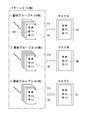
- FIG. 4 is a diagram showing the relationship between the substrate group and the mask.
- the substrate 8 (8A, 8B, 8C) of the pattern X manufactured based on the same design is used. Since printing is performed on a total of N substrates 8 by the screen printing machine 1, the substrate 8 is manufactured by three substrate manufacturers, and na substrate 8A, nb substrate 8B, and nc substrate 8C are prepared. ing.
- the substrates 8A, 8B, and 8C of different substrate manufacturers have different elongations of the substrates, that is, differences in errors (deviations) from design values.
- the substrates 8A, 8B, and 8C of the respective substrate manufacturers are divided into substrate groups A, B, and C, respectively, because the amount of pattern deviation is substantially constant for substrates manufactured in the same process and environment.
- the patterns formed on the substrates 8A, 8B, 8C are measured by a projection device or the like. If there is a difference in the amount of deviation from the design value, a board group is created for each amount of deviation (mostly for each substrate manufacturer).
- the board IDs 31 (31a, 31b, 31c) storing the respective information are given to the grouped boards 8A, 8B, 8C.
- the board ID 31 stores group information that specifies the board groups A, B, and C to which the boards 8A, 8B, and 8C belong, and deviation information from the design values of the boards 8A, 8B, and 8C.
- a mask 6 (6A, 6B, 6C) is prepared for each substrate group. In the masks 6A, 6B, 6C, print pattern holes corresponding to the amounts of pattern shifts formed in the substrates 8A, 8B, 8C are formed.
- FIG. 5 is a block diagram schematically showing a control system of the screen printing machine 1.
- the control device 18 of the screen printing machine 1 includes a microprocessor (CPU) 41, a ROM 42, a RAM 43, and a non-volatile memory 44 connected via a bus line, and constituting the screen printing machine 1 via an I / O port 45. It is connected to a drive unit such as a motor of the device.
- the screen printing machine 1 is provided with a touch panel type operation display device 47 capable of displaying data input, work contents, and the like, and is connected to the I / O port 45.
- a board ID reader 48 for reading the board ID 31 is connected to the control device 18.
- the connection between the control device 18 of the screen printing machine 1 and the drive unit is not limited to the one via the I / O port 45, but may be based on a field bus system based on Ethernet (registered trademark), optical communication, or the like. You may.
- the control device 19 of the automatic mask changing machine 2 is connected to the control device of the screen printing machine 1 via a communication cable. 18 is connected.
- an automatic mask exchange system in which the drive of the automatic mask exchange machine 2 is controlled based on the control command of the screen printing machine 1 is configured.
- an automatic mask exchange program 441 for selecting the corresponding mask 6 according to the substrate group and exchanging the mask in the screen printing machine 1 is stored in the nonvolatile memory 44.
- the board information for executing the mask automatic exchange program 441 is input to the control device 18 of the screen printing machine 1.
- the board information is provided by an operator from an operation display device 47 provided on the front surface of the body of the screen printing machine 1.
- the board information input here is the order of the boards 8 (board groups) to be conveyed to the screen printing machine 1 and the total number of boards 8 in each board group.
- mask information indicating the position of the slot 23 of the automatic exchange 2 at which the mask 6A, 6B, 6C corresponding to each of the substrates 8A, 8B, 8C is set is also input. Further, the value of the corresponding range which the set masks 6A, 6B, and 6C can cope with with respect to the design value, respectively, is also input.
- the substrates 8 are conveyed one by one, the cream solder is passed through the printing pattern holes from the upper surface side of the mask 6, and the pattern X is applied to the substrate 8 positioned on the lower surface side of the mask 6. Is printed. Printing is performed on the plurality of substrates 8 that are repeatedly transported, and printing is switched to the substrate of the next substrate group by using up the substrate in one substrate group, and the mask is automatically exchanged accordingly.
- the automatic replacement of the mask is performed based on, for example, information on the order of the substrate groups and the number of substrates in each group, which are input to the storage unit of the control device 18.
- the screen printing machine 1 when the substrate 8 is transported in the order of the substrate groups A, B, and C, the screen printing machine 1 is provided with a mask 6A for the substrate 8A. Therefore, when the printing process is started by the screen printing machine 1, the number of times of printing is counted each time printing using the mask 6A is performed, and the number of times of printing is compared with the number of substrates of the substrate group A.
- na which is the number of substrates in the substrate group A
- the mask 6 corresponding to the substrate 8 of the substrate group to be transported next is checked. Is selected.
- the automatic mask changer 2 since the substrate 8B of the substrate group B is transported, the automatic mask changer 2 replaces the substrate 8B with a mask 6B corresponding to the substrate 8B. Then, the printing on the substrate 8B using the mask 6B is repeated, and similarly, according to the completion of the printing of the number of substrates nb of the substrate group B, the replacement with the mask 6C corresponding to the substrate 8C is performed.
- a control command signal for the corresponding mask 6 is transmitted from the control device 18 of the screen printing machine 1 to the control device 19 of the automatic mask changing machine 2.
- the magazine rack 22 is raised as shown in FIGS. 2 to 3, and the empty slot 23 is positioned at a predetermined height. That is, the slot 23 into which the mask (for example, the mask 6A) used in the screen printing machine 1 is inserted is arranged at the receiving position, and the mask 6A gripped by the clamp device is pulled back. Thereafter, the magazine rack 22 moves up and down, the next mask 6B is sent out from the corresponding slot 23 to the screen printing machine 1, and the mask replacement is completed.
- the automatic mask replacement method may perform the mask replacement according to the number of substrates in the substrate group as described above, or may use the following method including a step of determining accuracy or suitability. .
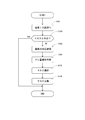
- FIG. 6 is a flowchart showing the mask automatic replacement method.
- the screen printer 1 is provided with a mask 6A for the substrate 8A.
- the substrate ID 31 is read by the substrate ID reader 48 (S101), and the correspondence with the mask 6 is confirmed (S102). That is, not only the comparison with the number of substrates in the substrate group, but also the confirmation of switching to the substrate 8B of the next group to be used is performed.
- the actual deviation amount of the captured pattern 801 is compared with the deviation amount information of the mask 6 stored in the storage unit of the control device 18 to determine the deviation amount conformity (S104).
- the amount of deviation from the design value of the substrate 8 or the mask 6 is a value that has been confirmed in advance, in the present embodiment, comparison with the actual amount of deviation of the substrate 8 is performed based on the imaging data. Therefore, the optimum mask 6 is selected by the deviation amount matching determination (S105).
- the mask 6B is selected and replaced (S106).
- the displacement amount of the transferred substrate 8B is within the range corresponding to the mask 6A, the mask 6A is selected. Therefore, in step S106, the replacement with the mask 6B is postponed, and the mask 6A is continuously used.
- the exchange to the mask 6C and the like are performed in the same manner through the deviation amount matching determination (S104) and the like. Done.
- the automatic change of the mask 6 in the automatic mask changing machine 2 is performed by paying attention to the fact that the amount of displacement of the board 8 on which printing is performed by the screen printing machine 1 differs for each board group.
- a suitable mask 6 can be used for 8. Since the automatic mask replacement method of the present embodiment is performed based on the substrate group, selection of the mask 6 is simple.
- a board group is set for each board maker, but may be a board group distinguished by another standard.
- a plurality of prepared masks 6 may be provided with mask IDs each storing the shift amount information of the corresponding range, and the IDs may be read and replaced when the masks are replaced.
- the camera unit 16 captures an image of a part of the pattern 801 of the substrate 8 and calculates the amount of deviation in step S103 (see FIG. 6). It may be used.
Landscapes
- Engineering & Computer Science (AREA)
- Mechanical Engineering (AREA)
- Screen Printers (AREA)
- Electric Connection Of Electric Components To Printed Circuits (AREA)
- Supply, Installation And Extraction Of Printed Sheets Or Plates (AREA)
Abstract
L'invention concerne un procédé de remplacement de masque automatique et un système de remplacement de masque automatique basés sur la correspondance entre un groupe de substrats et un masque. Le procédé comprend : une étape de transport de substrat consistant à transporter un substrat pour chaque groupe de substrats parmi des groupes de substrats distingués sur la base d'une quantité de déviation d'un motif formé sur le substrat par rapport à une machine de sérigraphie ; une étape de confirmation de substrat consistant à confirmer des informations de substrat pendant le transport du substrat dans l'étape de transport de substrat ; une étape de sélection de masque consistant à sélectionner, parmi une pluralité de masques préparés correspondant à la pluralité de groupes de substrats, un masque pertinent en fonction du résultat de l'étape de confirmation de substrat ; et une étape de remplacement de masque consistant à amener le masque pertinent à la machine de sérigraphie à partir d'une machine de remplacement de masque automatique recevant la pluralité de masques.
Priority Applications (2)
| Application Number | Priority Date | Filing Date | Title |
|---|---|---|---|
| PCT/JP2018/023402 WO2019244265A1 (fr) | 2018-06-20 | 2018-06-20 | Procédé de remplacement de masque automatique et système de remplacement de masque automatique |
| JP2020525138A JP7075488B2 (ja) | 2018-06-20 | 2018-06-20 | マスク自動交換方法およびマスク自動交換システム |
Applications Claiming Priority (1)
| Application Number | Priority Date | Filing Date | Title |
|---|---|---|---|
| PCT/JP2018/023402 WO2019244265A1 (fr) | 2018-06-20 | 2018-06-20 | Procédé de remplacement de masque automatique et système de remplacement de masque automatique |
Publications (1)
| Publication Number | Publication Date |
|---|---|
| WO2019244265A1 true WO2019244265A1 (fr) | 2019-12-26 |
Family
ID=68982786
Family Applications (1)
| Application Number | Title | Priority Date | Filing Date |
|---|---|---|---|
| PCT/JP2018/023402 WO2019244265A1 (fr) | 2018-06-20 | 2018-06-20 | Procédé de remplacement de masque automatique et système de remplacement de masque automatique |
Country Status (2)
| Country | Link |
|---|---|
| JP (1) | JP7075488B2 (fr) |
| WO (1) | WO2019244265A1 (fr) |
Cited By (4)
| Publication number | Priority date | Publication date | Assignee | Title |
|---|---|---|---|---|
| WO2022002915A1 (fr) * | 2020-06-30 | 2022-01-06 | Ekra Automatisierungssysteme Gmbh | Machine d'impression et système d'impression ayant un magasin d'écrans pour impression sur des substrats plans |
| CN115210078A (zh) * | 2020-06-05 | 2022-10-18 | Ckd株式会社 | 丝网掩模检查装置、焊料印刷检查装置以及丝网掩模的检查方法 |
| WO2023223392A1 (fr) * | 2022-05-16 | 2023-11-23 | 株式会社Fuji | Système d'impression |
| JP7390642B2 (ja) | 2019-10-11 | 2023-12-04 | パナソニックIpマネジメント株式会社 | 搬送装置 |
Citations (6)
| Publication number | Priority date | Publication date | Assignee | Title |
|---|---|---|---|---|
| US5226366A (en) * | 1992-02-11 | 1993-07-13 | Screen Masters, Inc. | Method and apparatus for aligning screens used for application of ink patterns to a substrate |
| JPH0671847A (ja) * | 1992-08-31 | 1994-03-15 | Taiyo Yuden Co Ltd | スクリーン印刷機 |
| JPH0623747U (ja) * | 1992-08-31 | 1994-03-29 | 太陽誘電株式会社 | 印刷用スクリーン交換装置 |
| JPH06305111A (ja) * | 1993-04-21 | 1994-11-01 | Japan Radio Co Ltd | クリーム半田印刷方法及び装置 |
| JPH07314639A (ja) * | 1994-05-30 | 1995-12-05 | Tani Denki Kogyo Kk | スクリーン版自動交換装置 |
| JPH09300581A (ja) * | 1996-05-15 | 1997-11-25 | Matsushita Electric Ind Co Ltd | スクリーン印刷方法 |
Family Cites Families (5)
| Publication number | Priority date | Publication date | Assignee | Title |
|---|---|---|---|---|
| JP2861332B2 (ja) * | 1990-08-28 | 1999-02-24 | 松下電器産業株式会社 | スクリーン印刷装置 |
| JPH04197684A (ja) * | 1990-11-28 | 1992-07-17 | Fujitsu Ltd | メタルマスクとそれを用いる自動スクリーン印刷装置 |
| JP2013018123A (ja) * | 2011-07-07 | 2013-01-31 | Panasonic Corp | スクリーン印刷機及びスクリーン印刷方法 |
| JP5666518B2 (ja) * | 2012-07-23 | 2015-02-12 | ヤマハ発動機株式会社 | スクリーン印刷装置 |
| JP6785404B2 (ja) * | 2016-06-23 | 2020-11-18 | パナソニックIpマネジメント株式会社 | スクリーン印刷装置及び部品実装ライン |
-
2018
- 2018-06-20 JP JP2020525138A patent/JP7075488B2/ja active Active
- 2018-06-20 WO PCT/JP2018/023402 patent/WO2019244265A1/fr active Application Filing
Patent Citations (6)
| Publication number | Priority date | Publication date | Assignee | Title |
|---|---|---|---|---|
| US5226366A (en) * | 1992-02-11 | 1993-07-13 | Screen Masters, Inc. | Method and apparatus for aligning screens used for application of ink patterns to a substrate |
| JPH0671847A (ja) * | 1992-08-31 | 1994-03-15 | Taiyo Yuden Co Ltd | スクリーン印刷機 |
| JPH0623747U (ja) * | 1992-08-31 | 1994-03-29 | 太陽誘電株式会社 | 印刷用スクリーン交換装置 |
| JPH06305111A (ja) * | 1993-04-21 | 1994-11-01 | Japan Radio Co Ltd | クリーム半田印刷方法及び装置 |
| JPH07314639A (ja) * | 1994-05-30 | 1995-12-05 | Tani Denki Kogyo Kk | スクリーン版自動交換装置 |
| JPH09300581A (ja) * | 1996-05-15 | 1997-11-25 | Matsushita Electric Ind Co Ltd | スクリーン印刷方法 |
Cited By (5)
| Publication number | Priority date | Publication date | Assignee | Title |
|---|---|---|---|---|
| JP7390642B2 (ja) | 2019-10-11 | 2023-12-04 | パナソニックIpマネジメント株式会社 | 搬送装置 |
| CN115210078A (zh) * | 2020-06-05 | 2022-10-18 | Ckd株式会社 | 丝网掩模检查装置、焊料印刷检查装置以及丝网掩模的检查方法 |
| WO2022002915A1 (fr) * | 2020-06-30 | 2022-01-06 | Ekra Automatisierungssysteme Gmbh | Machine d'impression et système d'impression ayant un magasin d'écrans pour impression sur des substrats plans |
| US12023906B2 (en) | 2020-06-30 | 2024-07-02 | Ekra Automatisierungssysteme Gmbh | Printing machine and printing system having screen magazine for printing on planar substrates |
| WO2023223392A1 (fr) * | 2022-05-16 | 2023-11-23 | 株式会社Fuji | Système d'impression |
Also Published As
| Publication number | Publication date |
|---|---|
| JP7075488B2 (ja) | 2022-05-25 |
| JPWO2019244265A1 (ja) | 2021-04-08 |
Similar Documents
| Publication | Publication Date | Title |
|---|---|---|
| WO2019244265A1 (fr) | Procédé de remplacement de masque automatique et système de remplacement de masque automatique | |
| CN109982853B (zh) | 印刷装置及收纳装置 | |
| CN103587228B (zh) | 丝网印刷设备、印刷物制造方法和基板制造方法 | |
| US6850855B2 (en) | Apparatus and method for inspecting working operations on circuit substrate, and system and method for fabricating electric circuit | |
| JP4449376B2 (ja) | スクリーン印刷機 | |
| JP5075747B2 (ja) | 電子回路製造方法および電子回路製造システム | |
| CN114585514B (zh) | 焊膏珠回收系统及方法 | |
| JP6965273B2 (ja) | 印刷装置 | |
| JPH11214900A (ja) | カメラ位置の偏差補正方法およびその装置、並びにカメラ位置補正用のダミー部品 | |
| JP2006108200A (ja) | はんだ印刷システム | |
| CN112105504B (zh) | 印刷装置 | |
| JP5739754B2 (ja) | 電子回路部品の立上がり防止方法および電子回路製造システム | |
| JP2008198730A (ja) | 表面実装機、スクリーン印刷装置及び実装ライン | |
| CN113366934A (zh) | 元件种类管理装置 | |
| KR20130090894A (ko) | 전자 부품 실장 장치 및 전자 부품 실장 방법 | |
| WO2012046494A1 (fr) | Appareil de montage de composant électronique | |
| JP4385807B2 (ja) | スクリーン印刷機 | |
| JP7002181B2 (ja) | スクリーン印刷機 | |
| JP5662875B2 (ja) | スクリーン印刷装置 | |
| JP7436608B2 (ja) | 印刷システム | |
| JP5122532B2 (ja) | 支持ピンの移載方法 | |
| JP4527131B2 (ja) | 実装機 | |
| JP2019209596A (ja) | 印刷装置および印刷装置の使用方法 | |
| DE102007015536A1 (de) | Vorrichtung und Verfahren zum Aufbringen eines viskosen Mediums auf Substrate | |
| JP7032526B2 (ja) | 印刷装置 |
Legal Events
| Date | Code | Title | Description |
|---|---|---|---|
| 121 | Ep: the epo has been informed by wipo that ep was designated in this application |
Ref document number: 18923673 Country of ref document: EP Kind code of ref document: A1 |
|
| ENP | Entry into the national phase |
Ref document number: 2020525138 Country of ref document: JP Kind code of ref document: A |
|
| NENP | Non-entry into the national phase |
Ref country code: DE |
|
| 122 | Ep: pct application non-entry in european phase |
Ref document number: 18923673 Country of ref document: EP Kind code of ref document: A1 |