WO2019244265A1 - Automatic mask replacement method and automatic mask replacement system - Google Patents
Automatic mask replacement method and automatic mask replacement system Download PDFInfo
- Publication number
- WO2019244265A1 WO2019244265A1 PCT/JP2018/023402 JP2018023402W WO2019244265A1 WO 2019244265 A1 WO2019244265 A1 WO 2019244265A1 JP 2018023402 W JP2018023402 W JP 2018023402W WO 2019244265 A1 WO2019244265 A1 WO 2019244265A1
- Authority
- WO
- WIPO (PCT)
- Prior art keywords
- substrate
- mask
- automatic
- screen printing
- printing machine
- Prior art date
Links
Images


Classifications
-
- B—PERFORMING OPERATIONS; TRANSPORTING
- B41—PRINTING; LINING MACHINES; TYPEWRITERS; STAMPS
- B41F—PRINTING MACHINES OR PRESSES
- B41F15/00—Screen printers
- B41F15/08—Machines
- B41F15/12—Machines with auxiliary equipment, e.g. for drying printed articles
-
- B—PERFORMING OPERATIONS; TRANSPORTING
- B41—PRINTING; LINING MACHINES; TYPEWRITERS; STAMPS
- B41F—PRINTING MACHINES OR PRESSES
- B41F27/00—Devices for attaching printing elements or formes to supports
- B41F27/12—Devices for attaching printing elements or formes to supports for attaching flexible printing formes
Abstract
An automatic mask replacement method and an automatic mask replacement system based on the correspondence between a substrate group and a mask. The method comprises: a substrate conveyance step of conveying a substrate for each of substrate groups distinguished on the basis of a deviation amount of a pattern formed on the substrate with respect to a screen printing machine; a substrate confirmation step of confirming substrate information during the conveyance of the substrate in the substrate conveyance step; a mask selection step of selecting, from a plurality of masks prepared corresponding to the plurality of substrate groups, a relevant mask according to the result of the substrate confirmation step; and a mask replacement step of feeding the relevant mask to the screen printing machine from an automatic mask replacement machine accommodating the plurality of masks.
Description
本発明は、スクリーン印刷機へのマスク交換を適切に行うためのマスク自動交換方法およびマスク自動交換システムに関する。
The present invention relates to an automatic mask changing method and an automatic mask changing system for appropriately changing a mask to a screen printing machine.
スクリーン印刷機は、印刷パターン孔の形成されたマスクが取り付けられ、その下側に搬送された基板が保持される。その基板は上昇してマスクの下面に接し、マスク上面側からはスキージ装置によってクリームはんだが塗り延ばしされ、印刷パターン孔を通ったクリームはんだが基板上に印刷される。下記特許文献1には、このようなスクリーン印刷機に関するマスクの自動交換技術が開示されている。そのスクリーン印刷機は、前述しように基板に対して印刷を行う印刷部を有し、その印刷部に対してマスクの出し入れを行う収納部が設けられている。収納部は、複数段のベルトコンベヤを備えたストッカを有し、そのストッカがシリンダによって昇降するように構成されている。
The screen printing machine is equipped with a mask in which a printing pattern hole is formed, and holds the conveyed substrate below the mask. The substrate rises and comes into contact with the lower surface of the mask. The cream solder is spread from the upper surface of the mask by a squeegee device, and the cream solder passing through the print pattern holes is printed on the substrate. Patent Document 1 listed below discloses an automatic mask exchange technology for such a screen printing machine. The screen printing machine has a printing unit for printing on a substrate as described above, and a storage unit for taking a mask in and out of the printing unit. The storage section has a stocker provided with a plurality of belt conveyors, and the stocker is configured to move up and down by a cylinder.
マスクの交換は、主に基板の品種変更にともなって行われる。その際、前記第1従来例では、シリンダの駆動によってストッカが昇降し、そのストッカに対するマスクの回収と、新たなマスクの印刷位置への送り出しが行われる。ところで、基板には伸縮が生じるため、マスクとの間にズレが生じてしまい、印刷精度を低下させてしまうことがある。この点について下記特許文献2には、基板の変形の程度に応じてマスクを選択するスクリーン印刷機が開示されている。この第2従来例では、基板に一対の基板側マークが設けられ、複数あるマスクの各々にも基板に対応したマスク側マークが設けられている。その基板側マークがカメラによって撮像され、一対の基板側マークの間の距離(実測値)から、設計値との比率に基づく基板の変形度が算出される。そして、算出された基板の変形度が複数あるマスクの開口パターンデータと比較され、ひとつのマスクが選択される。
Replacement of masks is mainly carried out when the type of substrate is changed. At that time, in the first conventional example, the stocker is moved up and down by driving the cylinder, and the collection of the mask for the stocker and the delivery of a new mask to the printing position are performed. By the way, since the substrate expands and contracts, there is a deviation between the substrate and the mask, which may lower the printing accuracy. In this regard, Patent Document 2 below discloses a screen printer that selects a mask according to the degree of deformation of a substrate. In the second conventional example, a pair of substrate side marks is provided on a substrate, and a mask side mark corresponding to the substrate is provided on each of a plurality of masks. The board-side mark is imaged by a camera, and the degree of deformation of the board is calculated from the distance (actually measured value) between the pair of board-side marks based on the ratio to the design value. Then, the calculated degree of deformation of the substrate is compared with the opening pattern data of a plurality of masks, and one mask is selected.
前記第2従来例は、フィルム状基板であることによって面内の伸縮変形が生じることの記載はあるものの、基板の変形については明確ではなく、基板が反って表面積が縮小している場合も含むとの記載から、基板の変形程度を個別に算出し、設計値との比率に基づいて基板の変形度が求められているようである。しかし、基板毎に変形度の算出を行っていたのでは生産効率を大きく低下させてしまうことになる。
In the second conventional example, although there is a description that in-plane expansion and contraction occurs due to being a film-shaped substrate, the deformation of the substrate is not clear, and includes a case where the substrate is warped and the surface area is reduced. From the description, it seems that the degree of deformation of the substrate is individually calculated, and the degree of deformation of the substrate is obtained based on the ratio with the design value. However, if the degree of deformation was calculated for each substrate, the production efficiency would be greatly reduced.
そこで、本発明は、かかる課題を解決すべく、基板グループとマスクとの対応関係に基づくマスク自動交換方法およびマスク自動交換システムを提供することを目的とする。
Therefore, an object of the present invention is to provide an automatic mask replacement method and a mask automatic replacement system based on the correspondence between a substrate group and a mask in order to solve the above problem.
本発明の一態様におけるマスク自動交換方法は、スクリーン印刷機に対して基板に形成されたパターンのズレ量に基づいて区別された基板グループ毎に基板を搬送する基板搬送工程と、前記基板搬送工程による基板の搬送に伴い基板情報を確認する基板確認工程と、複数の基板グループに対応して用意された複数のマスクから前記基板確認工程の結果に従い該当するマスクを選択するマスク選択工程と、前記複数のマスクを収納するマスク自動交換機から該当するマスクを前記スクリーン印刷機へ送り出すマスク交換工程とを有する。
The method for automatically exchanging a mask according to one aspect of the present invention includes a substrate transporting step of transporting a substrate for each substrate group distinguished based on a shift amount of a pattern formed on the substrate with respect to a screen printing machine; A board checking step of checking board information along with the transfer of the board, and a mask selecting step of selecting a corresponding mask from a plurality of masks prepared corresponding to a plurality of board groups according to the result of the board checking step; A mask exchanging step of sending a corresponding mask from the automatic mask exchanging machine accommodating a plurality of masks to the screen printing machine.
本発明の他の態様におけるマスク自動交換システムは、基板に対する搬送および、マスクに重ねた基板に対して当該マスクの印刷パターン孔を通したクリームはんだの印刷を行うスクリーン印刷機と、共通する複数の基板からなる基板グループ毎に用意された複数のマスクを収納し、該当するマスクを前記スクリーン印刷機へ送り出すマスク自動交換機と、前記スクリーン印刷機および前記マスク自動交換機を制御するものであって、所定の基板情報を基に前記基板グループ毎に該当するマスクを選択する制御装置とを有する。
A mask automatic exchange system according to another aspect of the present invention includes a screen printer that transfers a substrate, and prints cream solder through a print pattern hole of the mask on a substrate superimposed on the mask, and a plurality of common printers. A plurality of masks prepared for each substrate group made up of substrates are stored, and an automatic mask changing machine for sending a corresponding mask to the screen printing machine, and controlling the screen printing machine and the mask automatic changing machine, and And a controller for selecting a mask corresponding to each of the substrate groups based on the substrate information.
前記構成によれば、スクリーン印刷機に対して基板に形成されたパターンのズレ量に基づいて基板グループが設けられ、その基板グループ毎に基板が搬送される。そして、複数ある基板グループに対応して複数のマスクが用意され、基板グループごとの基板枚数など、所定の基板情報に基づいて該当するマスクが選択され、前の基板グループに使用されたマスクとの交換が行われる。
According to the above configuration, a substrate group is provided with respect to the screen printing machine based on a shift amount of a pattern formed on the substrate, and the substrate is transported for each substrate group. Then, a plurality of masks are prepared corresponding to the plurality of substrate groups, a corresponding mask is selected based on predetermined substrate information such as the number of substrates for each substrate group, and a mask with the mask used for the previous substrate group is selected. An exchange takes place.
次に、本発明に係るマスク自動交換方法およびマスク自動交換システムの一実施形態について、図面を参照しながら以下に説明する。本実施形態では、スクリーン印刷機にマスク自動交換機を外付けしたマスク自動交換システムおよび、そこで実行されるマスク自動交換方法について説明する。図1は、スクリーン印刷機の内部構造を簡略化して示した側面図である。このスクリーン印刷機1は、基板に対してクリームはんだを印刷するものであり、例えば印刷状態を検査する検査機や基板に対して電子部品の装着を行う部品装着機などと共に回路基板生産ラインを構成するものである。
Next, an embodiment of an automatic mask replacement method and an automatic mask replacement system according to the present invention will be described below with reference to the drawings. In the present embodiment, an automatic mask exchange system in which an automatic mask exchange machine is externally attached to a screen printing machine, and an automatic mask exchange method executed there will be described. FIG. 1 is a simplified side view showing the internal structure of the screen printing machine. The screen printing machine 1 prints cream solder on a substrate, and forms a circuit board production line together with, for example, an inspection machine for inspecting a printing state and a component mounting machine for mounting electronic components on the substrate. Is what you do.
スクリーン印刷機1では、機体内部にマスクが水平に取り付けられ、その下に基板が搬送および保持され、マスク上面から印刷パターン孔を通したクリームはんだが、そのマスクの下側に位置決めされた基板に塗布される。こうしたスクリーン印刷機1は、上部側にマスクホルダ11があり、マスクの取り付けが可能になっている。そして、マスクホルダ11の上方側には、マスク上のクリームはんだを機体前後方向(図面横方向)に塗り延ばしするスキージ装置12が設置されている。一方、マスクホルダ11の下側には、搬送された基板を保持して上下方向に移動させる基板保持昇降装置13が設けられている。
In the screen printing machine 1, a mask is mounted horizontally inside the machine body, a substrate is conveyed and held under the mask, and the cream solder passing through the printing pattern holes from the mask upper surface is applied to the substrate positioned below the mask. Applied. Such a screen printing machine 1 has a mask holder 11 on an upper side, so that a mask can be attached. A squeegee device 12 that spreads the cream solder on the mask in the longitudinal direction of the machine (horizontal direction in the drawing) is installed above the mask holder 11. On the other hand, below the mask holder 11, a substrate holding / lifting device 13 for holding the transported substrate and moving it in the vertical direction is provided.
スクリーン印刷機1は、図示するように機体カバー15によって覆われているが、機体幅方向の両側面部に搬送口151(図2参照)が形成され、基板の搬入及び搬出が行われるようになっている。そのため、基板保持昇降装置13には、機体幅方向(図面を貫く方向)に基板を搬送させる基板搬送装置が組み込まれている。更に、その基板保持昇降装置13は、搬送された基板を保持するクランプ装置や、保持した基板がマスク下面に接触する印刷位置へと昇降させる昇降装置なども組み込まれている。
The screen printing machine 1 is covered with a machine body cover 15 as shown in the figure, but transport ports 151 (see FIG. 2) are formed on both side portions in the machine body width direction, so that the substrate can be loaded and unloaded. ing. Therefore, the substrate holding / elevating device 13 incorporates a substrate transport device that transports the substrate in the machine body width direction (the direction through the drawing). Further, the substrate holding and raising / lowering device 13 incorporates a clamp device for holding the transported substrate, a lifting / lowering device for raising and lowering the held substrate to a printing position where the held substrate contacts the lower surface of the mask, and the like.
また、マスクホルダ11と基板保持昇降装置13の間には、基板やマスクに付された基準マークなどを撮像するカメラユニット16と、マスクの汚れを下面側から拭き取って清掃するクリーニングユニット17が設けられている。本実施形態のカメラユニット16は、基板に形成されたパターンの撮像にも使用されるよう構成されている。カメラユニット16およびクリーニングユニット17は、矢印A1の範囲を移動する駆動構成が設けられている。また、矢印A2の範囲が基板保持昇降装置13による基板の昇降範囲である。そして、スクリーン印刷機1には、こうした各装置の駆動を制御する制御装置18(図5参照)が搭載されている。
Further, between the mask holder 11 and the substrate holding / elevating device 13, a camera unit 16 for imaging a reference mark or the like attached to the substrate or the mask, and a cleaning unit 17 for wiping and removing dirt on the mask from the lower surface side are provided. Have been. The camera unit 16 of the present embodiment is configured to be used also for imaging a pattern formed on a substrate. The camera unit 16 and the cleaning unit 17 are provided with a drive configuration that moves in the range of the arrow A1. The range indicated by arrow A2 is the range in which the substrate is moved up and down by the substrate holding elevating device 13. The screen printing machine 1 is equipped with a control device 18 (see FIG. 5) for controlling the driving of each device.
スクリーン印刷機1では、搬送口151を通って搬入された基板がマスクの下で保持された後、上昇してマスクの下面に接触した印刷位置に位置決めされる。一方、マスクの上面ではスキージ装置12によってクリームはんだがローリングされる。そのため、印刷パターン孔を通ったクリームはんだがパターンに従って基板に塗布される。その後、基板が所定速度で下降することによりマスクからの版離れが行われ、パターンに従った印刷が完了する。スクリーン印刷機1での印刷は、生産計画に従った枚数の基板に対して同一の印刷が繰り返し行われるが、所定のタイミングでマスクの交換が行われる。
In the screen printing machine 1, the substrate carried in through the transfer port 151 is held under the mask, and then moved up and positioned at a printing position in contact with the lower surface of the mask. On the other hand, the squeegee device 12 rolls the cream solder on the upper surface of the mask. Therefore, the cream solder passing through the printed pattern holes is applied to the substrate according to the pattern. Thereafter, the plate is separated from the mask by lowering the substrate at a predetermined speed, and printing according to the pattern is completed. In the printing by the screen printing machine 1, the same printing is repeatedly performed on the number of substrates according to the production plan, but the mask is replaced at a predetermined timing.
例えば、生産枚数が多い場合には、複数の基板メーカによって製造された基板が使用されることがある。その場合、同一の設計に基づいて製造された基板であっても、メーカによってパターンに微妙な差が生じてしまう。すなわち、基板に形成されたパターンには設計値と比較して多少の誤差が生じてしまうが、各基板メーカにおける製造工程や、温度など製造環境の違いから、それぞれ基板の伸びに違いが生じてしまう。そうした基板におけるパターンの誤差に対してマスクを共通にしてしまうと、印刷パターン孔とのズレとなって印刷精度を低下させてしまうことになる。そこで、本実施形態では、基板メーカなどによって基板の伸び(ズレ量)に差が生じることに着目し、基板グループを作成して各々のグループに対応したマスクを予め用意することとした。
For example, when the number of substrates is large, substrates manufactured by a plurality of substrate manufacturers may be used. In this case, even if the substrates are manufactured based on the same design, a slight difference occurs in the pattern depending on the manufacturer. In other words, the pattern formed on the substrate will have some errors compared to the design values, but due to differences in the manufacturing process and the manufacturing environment such as temperature at each substrate manufacturer, differences will occur in the elongation of each substrate. I will. If a common mask is used for such a pattern error on the substrate, a deviation from the printing pattern hole will occur, and the printing accuracy will be reduced. Therefore, in the present embodiment, attention is paid to the fact that there is a difference in the elongation (deviation) of the substrate depending on the substrate maker or the like, and a substrate group is created and a mask corresponding to each group is prepared in advance.
次に、図2及び図3は、スクリーン印刷機1にマスク自動交換機2をセットした状態の側面図であり、特にマスク自動交換機について内部構造が示されている。図2は、マスク自動交換機の待機状態が示され、図3にはマスク自動交換機のマスク交換状態が示されている。このマスク自動交換機2は、スクリーン印刷機1の機体前面部に連結され、必要に応じてマスクの交換を自動で行うものである。そのマスク自動交換機2は、交換機本体21内に複数のマスク6が収納され、一枚ずつマスクを交換機本体21内からスクリーン印刷機1側に送り出し、或いは逆方向に引き戻すよう構成されたものである。
Next, FIGS. 2 and 3 are side views showing a state in which the automatic mask changing machine 2 is set on the screen printing machine 1. In particular, the internal structure of the automatic mask changing machine is shown. FIG. 2 shows a standby state of the automatic mask exchange, and FIG. 3 shows a mask exchange state of the automatic mask exchange. The automatic mask changing machine 2 is connected to the front of the body of the screen printing machine 1, and automatically changes masks as necessary. The automatic mask changing machine 2 is configured such that a plurality of masks 6 are housed in a changing machine main body 21 and the masks are sent out one by one from the inside of the changing machine main body 21 to the screen printing machine 1 side or pulled back in the opposite direction. .
マスク自動交換機2は、交換機本体21の内部にマガジンラック22が収納され、そのマガジンラック22には複数のマスク6が水平な状態で上下方向に並べて収納されている。マガジンラック22は、マスク6を一枚ずつ入れるスロット23が上下に複数段形成され、各スロット23に対して用意されたマスク6が一枚ずつ挿入できるようになっている。特に、スロット23は、機体の前後方向(図面横方向)にマスク6の出し入れが可能な構成を有し、同方向における外部からマガジンラック22へのマスク6の出し入れや、スクリーン印刷機1に対するマスクの交換が可能になっている。
In the automatic mask changing machine 2, a magazine rack 22 is housed inside the main body 21 of the machine, and a plurality of masks 6 are housed in the magazine rack 22 in a vertical state in a horizontal state. The magazine rack 22 is formed with a plurality of upper and lower slots 23 in which the masks 6 are inserted one by one, so that the masks 6 prepared for the respective slots 23 can be inserted one by one. In particular, the slot 23 has a configuration in which the mask 6 can be taken in and out in the front-rear direction (horizontal direction in the drawing) of the machine body, and the mask 6 can be taken in and out of the magazine rack 22 from the outside in the same direction, and the mask for the screen printing machine 1. Can be exchanged.
マガジンラック22は、昇降スライド25と一体に形成され、交換機本体21の壁面に形成された鉛直方向のガイドレール26に対して摺動可能に組み付けられている。2本のガイドレール26の間には、駆動モータによって回転するネジ軸27が鉛直方向に設けられ、そのネジ軸27が昇降スライド25に固定された送りナットに螺合し、ボールネジ機構が構成されている。従って、駆動モータの回転制御によりマガジンラック22が昇降し、該当するマスク6をスクリーン印刷機1との交換口に位置決めさせることができるようになっている。
The magazine rack 22 is formed integrally with the elevating slide 25 and is slidably mounted on a vertical guide rail 26 formed on the wall surface of the exchange body 21. A screw shaft 27 that is rotated by a drive motor is provided in a vertical direction between the two guide rails 26, and the screw shaft 27 is screwed to a feed nut fixed to the elevating slide 25 to form a ball screw mechanism. ing. Accordingly, the magazine rack 22 is moved up and down by the rotation control of the drive motor, and the corresponding mask 6 can be positioned at the exchange port with the screen printing machine 1.
マガジンラック22は、スロット23の位置に合わせるようにして、両側面にガイド用の長孔221が複数形成され、詳しく図示しないが、その長孔221を通して両側面側からマスク6を挟持する一対のクランプ装置が設けられている。そして、そのクランプ装置には、上下に並んだ長孔221の位置に合わせて昇降させる不図示の昇降装置と、更に長孔221に沿って機体前後方向へ移動させるスライド装置28とが一体に構成されている。マスク6は、矩形のフレーム部材の内側に張った状態で取り付けられたものであるが、マスク自動交換機2では、クランプ装置によってマスク6のフレーム部材を両側から把持し、水平に移動させることによりスクリーン印刷機1内のマスクホルダ11へとマスク6が送られるようになっている。
The magazine rack 22 is formed with a plurality of long holes 221 for guiding on both side surfaces so as to match the position of the slot 23. Although not shown in detail, a pair of long holes 221 for holding the mask 6 from the both side surfaces through the long holes 221 is provided. A clamping device is provided. The clamp device is integrally formed with a lifting device (not shown) that moves up and down in accordance with the positions of the long holes 221 arranged vertically and a slide device 28 that moves in the vehicle longitudinal direction along the long holes 221. Have been. The mask 6 is attached in a state where it is stretched inside a rectangular frame member. In the automatic mask exchanging machine 2, the frame member of the mask 6 is gripped from both sides by a clamping device and is moved horizontally to thereby screen. The mask 6 is sent to a mask holder 11 in the printing press 1.
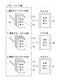
マスク自動交換機2内に収納された複数のマスク6は、前述したように、印刷対象となる基板の基板グループに対応して製作されたものである。ここで、図4は、基板グループとマスクとの関係を示した図である。本実施形態では、同じ設計を基に製造されたパターンXの基板8(8A,8B,8C)が使用されるものとする。スクリーン印刷機1によって合計N枚の基板8に対する印刷を行うため、3つの基板メーカによって製造されたものであり、基板8Aがna枚、基板8Bがnb枚、そして基板8Cがnc枚それぞれ用意されている。
As described above, the plurality of masks 6 housed in the automatic mask changer 2 are manufactured corresponding to the substrate group of the substrate to be printed. Here, FIG. 4 is a diagram showing the relationship between the substrate group and the mask. In the present embodiment, it is assumed that the substrate 8 (8A, 8B, 8C) of the pattern X manufactured based on the same design is used. Since printing is performed on a total of N substrates 8 by the screen printing machine 1, the substrate 8 is manufactured by three substrate manufacturers, and na substrate 8A, nb substrate 8B, and nc substrate 8C are prepared. ing.
異なる基板メーカの基板8A,8B,8Cは、前述したように基板の伸び、すなわち設計値との誤差(ズレ量)に違いが生じてしまっている。一方で、同じ工程や環境で製作された基板はパターンのズレ量はほぼ一定であるため、各基板メーカの基板8A,8B,8Cがそれぞれ基板グループA,B,Cに分けられる。例えば、基板8A,8B,8Cに形成されたパターンは、投影機器などによって測定される。そして、設計値とのズレ量に違いがあれば、そのズレ量ごと(多くは基板メーカごと)に区別した基板グループがつくられる。
(4) As described above, the substrates 8A, 8B, and 8C of different substrate manufacturers have different elongations of the substrates, that is, differences in errors (deviations) from design values. On the other hand, the substrates 8A, 8B, and 8C of the respective substrate manufacturers are divided into substrate groups A, B, and C, respectively, because the amount of pattern deviation is substantially constant for substrates manufactured in the same process and environment. For example, the patterns formed on the substrates 8A, 8B, 8C are measured by a projection device or the like. If there is a difference in the amount of deviation from the design value, a board group is created for each amount of deviation (mostly for each substrate manufacturer).
グループ分けされた基板8A,8B,8Cには、各々の情報を格納した基板ID31(31a,31b,31c)が付されている。その基板ID31には、基板8A,8B,8Cが属する基板グループA,B,Cを特定するグループ情報や、基板8A,8B,8Cにおける設計値とのズレ量情報が格納されている。そして、本実施形態では、その基板グループごとにマスク6(6A,6B,6C)が用意される。マスク6A,6B,6Cには、基板8A,8B,8Cに形成されたパターンのズレ量に対応した印刷パターン孔が形成されている。
(4) The board IDs 31 (31a, 31b, 31c) storing the respective information are given to the grouped boards 8A, 8B, 8C. The board ID 31 stores group information that specifies the board groups A, B, and C to which the boards 8A, 8B, and 8C belong, and deviation information from the design values of the boards 8A, 8B, and 8C. In this embodiment, a mask 6 (6A, 6B, 6C) is prepared for each substrate group. In the masks 6A, 6B, 6C, print pattern holes corresponding to the amounts of pattern shifts formed in the substrates 8A, 8B, 8C are formed.
次に、図5は、スクリーン印刷機1の制御システムを簡易的に示したブロック図である。スクリーン印刷機1の制御装置18は、マイクロプロセッサ(CPU)41、ROM42、RAM43、不揮発性メモリ44がバスラインを介して接続され、I/Oポート45を介してスクリーン印刷機1を構成する各装置のモータなど駆動部に接続されている。スクリーン印刷機1には、データ入力や作業内容などの表示が可能なタッチパネル型の操作表示装置47が取り付けられ、I/Oポート45に接続されている。また、制御装置18には、基板ID31を読み取る基板用IDリーダ48が接続されている。なお、スクリーン印刷機1の制御装置18と駆動部などの接続は、I/Oポート45を介すものに限られず、イーサネット(登録商標)などに基づくフィールドバスシステムや光通信などによるものであってもよい。
Next, FIG. 5 is a block diagram schematically showing a control system of the screen printing machine 1. The control device 18 of the screen printing machine 1 includes a microprocessor (CPU) 41, a ROM 42, a RAM 43, and a non-volatile memory 44 connected via a bus line, and constituting the screen printing machine 1 via an I / O port 45. It is connected to a drive unit such as a motor of the device. The screen printing machine 1 is provided with a touch panel type operation display device 47 capable of displaying data input, work contents, and the like, and is connected to the I / O port 45. Further, a board ID reader 48 for reading the board ID 31 is connected to the control device 18. The connection between the control device 18 of the screen printing machine 1 and the drive unit is not limited to the one via the I / O port 45, but may be based on a field bus system based on Ethernet (registered trademark), optical communication, or the like. You may.
スクリーン印刷機1に対してマスク自動交換機2が使用される場合には、両者が機械的に連結されるとともに、通信ケーブルを介してマスク自動交換機2の制御装置19がスクリーン印刷機1の制御装置18に接続される。こうしてスクリーン印刷機1側の制御指令に基づき、マスク自動交換機2側の駆動が制御されるマスク自動交換システムが構成される。スクリーン印刷機1の制御装置18には、その不揮発性メモリ44内に基板グループに従って対応するマスク6を選択し、スクリーン印刷機1でのマスク交換を行うマスク自動交換プログラム441が格納されている。
When the automatic mask changing machine 2 is used for the screen printing machine 1, both are mechanically connected, and the control device 19 of the automatic mask changing machine 2 is connected to the control device of the screen printing machine 1 via a communication cable. 18 is connected. In this way, an automatic mask exchange system in which the drive of the automatic mask exchange machine 2 is controlled based on the control command of the screen printing machine 1 is configured. In the control device 18 of the screen printing machine 1, an automatic mask exchange program 441 for selecting the corresponding mask 6 according to the substrate group and exchanging the mask in the screen printing machine 1 is stored in the nonvolatile memory 44.
そして、マスク自動交換プログラム441を実行するための基板情報が、スクリーン印刷機1の制御装置18に入力される。その基板情報は、スクリーン印刷機1の機体前面部に設けられた操作表示装置47から作業者によって行われる。ここでの入力される基板情報とは、スクリーン印刷機1へ搬送される基板8(基板グループ)の順番と、各基板グループの基板8の合計枚数である。また、各々の基板8A,8B,8Cに対応するマスク6A,6B,6Cが、自動交換機2のどの位置のスロット23にセットされているかを示すマスク情報なども入力される。更に、セットされたマスク6A,6B,6Cが、それぞれ設計値に対してどの程度の範囲のズレ量に対応可能なのか、対応可能範囲の値も入力される。
Then, the board information for executing the mask automatic exchange program 441 is input to the control device 18 of the screen printing machine 1. The board information is provided by an operator from an operation display device 47 provided on the front surface of the body of the screen printing machine 1. The board information input here is the order of the boards 8 (board groups) to be conveyed to the screen printing machine 1 and the total number of boards 8 in each board group. Further, mask information indicating the position of the slot 23 of the automatic exchange 2 at which the mask 6A, 6B, 6C corresponding to each of the substrates 8A, 8B, 8C is set is also input. Further, the value of the corresponding range which the set masks 6A, 6B, and 6C can cope with with respect to the design value, respectively, is also input.
続いて、スクリーン印刷機1において行われるマスク自動交換方法について説明する。スクリーン印刷機1では、前述したように基板8が一枚ずつ搬送され、マスク6の上面側から印刷パターン孔にクリームはんだを通し、マスク6の下面側に位置決めされた基板8に対してパターンXの印刷が行われる。繰り返し搬送される複数の基板8に対して印刷が行われ、一の基板グループにおける基板の使い切りにより、次の基板グループの基板へと印刷が切り換えられ、それに合わせてマスクの自動交換が行われる。
Next, a description will be given of an automatic mask replacement method performed in the screen printing machine 1. In the screen printing machine 1, as described above, the substrates 8 are conveyed one by one, the cream solder is passed through the printing pattern holes from the upper surface side of the mask 6, and the pattern X is applied to the substrate 8 positioned on the lower surface side of the mask 6. Is printed. Printing is performed on the plurality of substrates 8 that are repeatedly transported, and printing is switched to the substrate of the next substrate group by using up the substrate in one substrate group, and the mask is automatically exchanged accordingly.
マスクの自動交換は、例えば、制御装置18の記憶部に入力された基板グループの順番やグループ毎の基板枚数の情報に基づいて行われる。このマスク自動交換方法では、基板グループA,B,Cの順番に基板8が搬送されるとした場合、スクリーン印刷機1には基板8Aに対するマスク6Aが取り付けられる。そこで、スクリーン印刷機1によって印刷処理が開始されると、マスク6Aを使用した印刷が行われる度にその印刷回数がカウントされ、印刷回数と基板グループAの基板枚数との比較が行われる。
The automatic replacement of the mask is performed based on, for example, information on the order of the substrate groups and the number of substrates in each group, which are input to the storage unit of the control device 18. In this automatic mask replacement method, when the substrate 8 is transported in the order of the substrate groups A, B, and C, the screen printing machine 1 is provided with a mask 6A for the substrate 8A. Therefore, when the printing process is started by the screen printing machine 1, the number of times of printing is counted each time printing using the mask 6A is performed, and the number of times of printing is compared with the number of substrates of the substrate group A.
すなわち、印刷回数が基板グループAの基板枚数であるnaに達したか否かについて確認が行われ、その結果、達している場合には次に搬送される基板グループの基板8に対応したマスク6が選択される。本実施形態では、基板グループBの基板8Bが搬送されるため、マスク自動交換機2によって基板8Bに対応するマスク6Bへの交換が行われる。そして、マスク6Bを使用した基板8Bへの印刷が繰り返され、同じようにして基板グループBの基板枚数nbの印刷完了に従い、基板8Cに対応するマスク6Cへの交換が行われる。
That is, whether or not the number of times of printing has reached na, which is the number of substrates in the substrate group A, is checked. As a result, if the number has reached, the mask 6 corresponding to the substrate 8 of the substrate group to be transported next is checked. Is selected. In the present embodiment, since the substrate 8B of the substrate group B is transported, the automatic mask changer 2 replaces the substrate 8B with a mask 6B corresponding to the substrate 8B. Then, the printing on the substrate 8B using the mask 6B is repeated, and similarly, according to the completion of the printing of the number of substrates nb of the substrate group B, the replacement with the mask 6C corresponding to the substrate 8C is performed.
印刷回数が各基板グループの基板枚数に達した場合には、スクリーン印刷機1の制御装置18からマスク自動交換機2の制御装置19へ、該当するマスク6に対する交換指令信号が送信される。マスク自動交換機2では、マガジンラック22が図2から図3に示すように上昇し、空になっているスロット23が所定の高さに位置決めされる。すなわち、スクリーン印刷機1で使用されたマスク(例えばマスク6A)が挿入されるスロット23が受取り位置に配置され、クランプ装置によって把持されたマスク6Aが引き戻される。その後、マガジンラック22が上下動し、該当するスロット23から次のマスク6Bがスクリーン印刷機1側に送り出され、マスク交換が完了する。
(4) When the number of times of printing reaches the number of substrates in each substrate group, a control command signal for the corresponding mask 6 is transmitted from the control device 18 of the screen printing machine 1 to the control device 19 of the automatic mask changing machine 2. In the automatic mask changing machine 2, the magazine rack 22 is raised as shown in FIGS. 2 to 3, and the empty slot 23 is positioned at a predetermined height. That is, the slot 23 into which the mask (for example, the mask 6A) used in the screen printing machine 1 is inserted is arranged at the receiving position, and the mask 6A gripped by the clamp device is pulled back. Thereafter, the magazine rack 22 moves up and down, the next mask 6B is sent out from the corresponding slot 23 to the screen printing machine 1, and the mask replacement is completed.
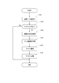
マスク自動交換方法は、このように基板グループの基板枚数に従ったマスク交換を行うようにしても良いが、正確性や適合性を判断する工程を加えた次のような方法であってもよい。図6は、そのマスク自動交換方法を示すフローチャートである。先ず、基板グループA,B,Cの順番に基板8が使用されるため、スクリーン印刷機1には基板8Aに対するマスク6Aが取り付けられている。その状態でスクリーン印刷機1に搬送される基板8について、基板ID31が基板用IDリーダ48によって読み取られ(S101)、マスク6との対応確認が行われる(S102)。つまり、基板グループの基板枚数との比較だけではなく、次に使用されるグループの基板8Bへの切り換わりの確認が行われる。
The automatic mask replacement method may perform the mask replacement according to the number of substrates in the substrate group as described above, or may use the following method including a step of determining accuracy or suitability. . FIG. 6 is a flowchart showing the mask automatic replacement method. First, since the substrates 8 are used in the order of the substrate groups A, B, and C, the screen printer 1 is provided with a mask 6A for the substrate 8A. With respect to the substrate 8 conveyed to the screen printing machine 1 in this state, the substrate ID 31 is read by the substrate ID reader 48 (S101), and the correspondence with the mask 6 is confirmed (S102). That is, not only the comparison with the number of substrates in the substrate group, but also the confirmation of switching to the substrate 8B of the next group to be used is performed.
搬送された基板8がマスク6Aと対応している場合には(S102:YES)、本処理が終了してマスク6Aはそのまま使用が継続される。一方、搬送された基板8がマスク6Aと対応していない場合(S102:NO)、つまり基板グループAの基板8Aについて印刷が全て終了し、次の基板8Bが送られた場合には、マスクの交換に向けた処理が行われる。本実施形態では、カメラユニット16によって搬送された基板8Bに付された一部のパターン801(図4参照)が撮像され、その撮像データから設計値との誤差(伸び)に関するズレ量が算出される(S103)。
(4) If the transferred substrate 8 corresponds to the mask 6A (S102: YES), this process ends, and the mask 6A continues to be used. On the other hand, if the transported substrate 8 does not correspond to the mask 6A (S102: NO), that is, if all the printing has been completed for the substrate 8A of the substrate group A and the next substrate 8B has been sent, the mask Processing for replacement is performed. In the present embodiment, a part of the pattern 801 (see FIG. 4) attached to the substrate 8B conveyed by the camera unit 16 is imaged, and a deviation amount relating to an error (elongation) from a design value is calculated from the imaged data. (S103).
そして、撮像されたパターン801の実際のズレ量について、制御装置18の記憶部に格納されているマスク6のズレ量情報と比較したズレ量適合判定が行なわれる(S104)。基板8やマスク6における設計値とのズレ量は予め確認された値であるが、本実施形態では撮像データから実際の基板8のズレ量との比較が行われるようになっている。従って、このズレ量適合判定により最適なマスク6が選択される(S105)。
(4) Then, the actual deviation amount of the captured pattern 801 is compared with the deviation amount information of the mask 6 stored in the storage unit of the control device 18 to determine the deviation amount conformity (S104). Although the amount of deviation from the design value of the substrate 8 or the mask 6 is a value that has been confirmed in advance, in the present embodiment, comparison with the actual amount of deviation of the substrate 8 is performed based on the imaging data. Therefore, the optimum mask 6 is selected by the deviation amount matching determination (S105).
例えば、搬送された基板8Bのズレ量が情報通りであればマスク6Bが選択され、その交換が行われる(S106)。一方、仮に搬送された基板8Bのズレ量が、マスク6Aが対応する範囲のズレ量であるような場合にはマスク6Aが選択される。そのため、ステップS106においてマスク6Bへの交換は見送られ、継続してマスク6Aが使用される。そして、基板Bに対する印刷が繰り返され、搬送された基板が基板グループCの基板8Cへ切り換えられた場合には、同じようにしてズレ量適合判定(S104)などを経てマスク6Cへの交換などが行われる。
For example, if the displacement amount of the transported substrate 8B is in accordance with the information, the mask 6B is selected and replaced (S106). On the other hand, if the displacement amount of the transferred substrate 8B is within the range corresponding to the mask 6A, the mask 6A is selected. Therefore, in step S106, the replacement with the mask 6B is postponed, and the mask 6A is continuously used. Then, when the printing on the substrate B is repeated and the transported substrate is switched to the substrate 8C of the substrate group C, the exchange to the mask 6C and the like are performed in the same manner through the deviation amount matching determination (S104) and the like. Done.
従って、本実施形態によれば、スクリーン印刷機1により印刷を行う基板8のズレ量が基板グループ毎に異なることに着目し、マスク自動交換機2におけるマスク6の自動交換を行うようにしたため、基板8に対して適切なマスク6を使用することができる。そして、本実施形態のマスク自動交換方法は、基板グループを基準にして行うためマスク6の選択が簡単である。
Therefore, according to the present embodiment, the automatic change of the mask 6 in the automatic mask changing machine 2 is performed by paying attention to the fact that the amount of displacement of the board 8 on which printing is performed by the screen printing machine 1 differs for each board group. A suitable mask 6 can be used for 8. Since the automatic mask replacement method of the present embodiment is performed based on the substrate group, selection of the mask 6 is simple.
以上、本発明の一実施形態について説明したが、本発明はこれらに限定されるものではなく、その趣旨を逸脱しない範囲で様々な変更が可能である。
例えば、前記実施形態では基板メーカ毎に基板グループを設定したが、別の基準によって区別した基板グループであってもよい。
また、例えば、用意された複数のマスク6にも各々が対応する範囲のズレ量情報を格納したマスクIDを付し、マスク交換時にIDを読み取って改めて確認するようにしてもよい。
また、前記実施形態では、ステップS103(図6参照)においてカメラユニット16が基板8の一部のパターン801を撮像してズレ量を算出しているが、基板8に付した測定用のマークを使用するものであってもよい。 As mentioned above, although one Embodiment of this invention was described, this invention is not limited to these, A various change is possible in the range which does not deviate from the meaning.
For example, in the above-described embodiment, a board group is set for each board maker, but may be a board group distinguished by another standard.
Further, for example, a plurality ofprepared masks 6 may be provided with mask IDs each storing the shift amount information of the corresponding range, and the IDs may be read and replaced when the masks are replaced.
Further, in the above-described embodiment, thecamera unit 16 captures an image of a part of the pattern 801 of the substrate 8 and calculates the amount of deviation in step S103 (see FIG. 6). It may be used.
例えば、前記実施形態では基板メーカ毎に基板グループを設定したが、別の基準によって区別した基板グループであってもよい。
また、例えば、用意された複数のマスク6にも各々が対応する範囲のズレ量情報を格納したマスクIDを付し、マスク交換時にIDを読み取って改めて確認するようにしてもよい。
また、前記実施形態では、ステップS103(図6参照)においてカメラユニット16が基板8の一部のパターン801を撮像してズレ量を算出しているが、基板8に付した測定用のマークを使用するものであってもよい。 As mentioned above, although one Embodiment of this invention was described, this invention is not limited to these, A various change is possible in the range which does not deviate from the meaning.
For example, in the above-described embodiment, a board group is set for each board maker, but may be a board group distinguished by another standard.
Further, for example, a plurality of
Further, in the above-described embodiment, the
1…スクリーン印刷機 2…マスク自動交換機 6(6A,6B,6C)…マスク 8(8A,8B,8C)…基板 11…マスクホルダ 18…制御装置 22…マガジンラック 23…スロット 31(31a,31b,31c)…基板ID 47…操作表示装置 48…基板用IDリーダ
DESCRIPTION OFSYMBOLS 1 ... Screen printing machine 2 ... Mask automatic exchange machine 6 (6A, 6B, 6C) ... Mask 8 (8A, 8B, 8C) ... Substrate 11 ... Mask holder 18 ... Control device 22 ... Magazine rack 23 ... Slot 31 (31a, 31b) , 31c) ... board ID 47 ... operation display device 48 ... board ID reader
DESCRIPTION OF
Claims (5)
- スクリーン印刷機に対して基板に形成されたパターンのズレ量に基づいて区別された基板グループ毎に基板を搬送する基板搬送工程と、
前記基板搬送工程による基板の搬送に伴い基板情報を確認する基板確認工程と、
複数の基板グループに対応して用意された複数のマスクから前記基板確認工程の結果に従い該当するマスクを選択するマスク選択工程と、
前記複数のマスクを収納するマスク自動交換機から該当するマスクを前記スクリーン印刷機へ送り出すマスク交換工程と、
を有するマスク自動交換方法。 A board transporting step of transporting the board for each board group distinguished based on the amount of displacement of the pattern formed on the board for the screen printing machine,
A board confirmation step of confirming board information along with the board transfer in the board transfer step,
A mask selecting step of selecting a corresponding mask from a plurality of masks prepared corresponding to a plurality of substrate groups according to the result of the substrate checking step;
A mask replacement step of sending a corresponding mask from the mask automatic changer containing the plurality of masks to the screen printing machine,
Automatic mask replacement method having the following. - 前記基板確認工程は、前記基板グループの基板枚数を前記基板情報として確認するものである請求項1に記載のマスク自動交換方法。 4. The method according to claim 1, wherein the substrate checking step includes checking the number of substrates in the substrate group as the substrate information.
- 前記基板確認工程は、前記基板に付された基板IDをIDリーダで読み取ることによって得られる前記基板情報を確認するものである請求項1又は請求項2に記載のマスク自動交換方法。 The method according to claim 1 or 2, wherein the substrate confirmation step is for confirming the substrate information obtained by reading a substrate ID attached to the substrate with an ID reader.
- 前記基板に付されたマーク又はパターンを撮像装置により撮像する撮像工程と、
前記撮像工程によって得られた撮像データからパターンのズレ量を算出する算出工程と、
前記算出工程によって得られたズレ量に基づいてマスク交換の有無を判定する交換判定工程と、
を有する請求項1乃至請求項3に記載のマスク自動交換方法。 An imaging step of imaging the mark or pattern attached to the substrate by an imaging device,
A calculating step of calculating a pattern shift amount from the imaging data obtained in the imaging step,
An exchange determining step of determining whether or not to replace the mask based on the amount of deviation obtained in the calculating step,
4. The automatic mask replacement method according to claim 1, further comprising: - 基板に対する搬送および、マスクに重ねた基板に対して当該マスクの印刷パターン孔を通したクリームはんだの印刷を行うスクリーン印刷機と、
共通する複数の基板からなる基板グループ毎に用意された複数のマスクを収納し、該当するマスクを前記スクリーン印刷機へ送り出すマスク自動交換機と、
前記スクリーン印刷機および前記マスク自動交換機を制御するものであって、所定の基板情報を基に前記基板グループ毎に該当するマスクを選択する制御装置と、
を有するマスク自動交換システム。
Conveyance to the substrate, and a screen printing machine that prints cream solder through the print pattern holes of the mask on the substrate overlaid on the mask,
A mask automatic exchange that stores a plurality of masks prepared for each substrate group consisting of a plurality of common substrates and sends the corresponding mask to the screen printing machine,
A control device that controls the screen printing machine and the mask automatic changer, and selects a mask corresponding to each of the substrate groups based on predetermined substrate information,
Automatic mask replacement system having a mask.
Priority Applications (2)
| Application Number | Priority Date | Filing Date | Title |
|---|---|---|---|
| JP2020525138A JP7075488B2 (en) | 2018-06-20 | 2018-06-20 | Automatic mask replacement method and automatic mask replacement system |
| PCT/JP2018/023402 WO2019244265A1 (en) | 2018-06-20 | 2018-06-20 | Automatic mask replacement method and automatic mask replacement system |
Applications Claiming Priority (1)
| Application Number | Priority Date | Filing Date | Title |
|---|---|---|---|
| PCT/JP2018/023402 WO2019244265A1 (en) | 2018-06-20 | 2018-06-20 | Automatic mask replacement method and automatic mask replacement system |
Publications (1)
| Publication Number | Publication Date |
|---|---|
| WO2019244265A1 true WO2019244265A1 (en) | 2019-12-26 |
Family
ID=68982786
Family Applications (1)
| Application Number | Title | Priority Date | Filing Date |
|---|---|---|---|
| PCT/JP2018/023402 WO2019244265A1 (en) | 2018-06-20 | 2018-06-20 | Automatic mask replacement method and automatic mask replacement system |
Country Status (2)
| Country | Link |
|---|---|
| JP (1) | JP7075488B2 (en) |
| WO (1) | WO2019244265A1 (en) |
Cited By (3)
| Publication number | Priority date | Publication date | Assignee | Title |
|---|---|---|---|---|
| JP2021062513A (en) * | 2019-10-11 | 2021-04-22 | パナソニックIpマネジメント株式会社 | Conveying device |
| WO2022002915A1 (en) * | 2020-06-30 | 2022-01-06 | Ekra Automatisierungssysteme Gmbh | Printing machine and printing system having screen magazine for printing on planar substrates |
| WO2023223392A1 (en) * | 2022-05-16 | 2023-11-23 | 株式会社Fuji | Printing system |
Citations (6)
| Publication number | Priority date | Publication date | Assignee | Title |
|---|---|---|---|---|
| US5226366A (en) * | 1992-02-11 | 1993-07-13 | Screen Masters, Inc. | Method and apparatus for aligning screens used for application of ink patterns to a substrate |
| JPH0671847A (en) * | 1992-08-31 | 1994-03-15 | Taiyo Yuden Co Ltd | Screen printing machine |
| JPH0623747U (en) * | 1992-08-31 | 1994-03-29 | 太陽誘電株式会社 | Screen exchange device for printing |
| JPH06305111A (en) * | 1993-04-21 | 1994-11-01 | Japan Radio Co Ltd | Method and apparatus for printing cream solder |
| JPH07314639A (en) * | 1994-05-30 | 1995-12-05 | Tani Denki Kogyo Kk | Automatic screen stencil changer |
| JPH09300581A (en) * | 1996-05-15 | 1997-11-25 | Matsushita Electric Ind Co Ltd | Screen printing method |
Family Cites Families (5)
| Publication number | Priority date | Publication date | Assignee | Title |
|---|---|---|---|---|
| JP2861332B2 (en) * | 1990-08-28 | 1999-02-24 | 松下電器産業株式会社 | Screen printing equipment |
| JPH04197684A (en) * | 1990-11-28 | 1992-07-17 | Fujitsu Ltd | Metal mask and automatic screen printing press using the same mask |
| JP2013018123A (en) | 2011-07-07 | 2013-01-31 | Panasonic Corp | Screen printing machine and screen printing method |
| JP5666518B2 (en) | 2012-07-23 | 2015-02-12 | ヤマハ発動機株式会社 | Screen printing device |
| JP6785404B2 (en) | 2016-06-23 | 2020-11-18 | パナソニックIpマネジメント株式会社 | Screen printing equipment and component mounting line |
-
2018
- 2018-06-20 JP JP2020525138A patent/JP7075488B2/en active Active
- 2018-06-20 WO PCT/JP2018/023402 patent/WO2019244265A1/en active Application Filing
Patent Citations (6)
| Publication number | Priority date | Publication date | Assignee | Title |
|---|---|---|---|---|
| US5226366A (en) * | 1992-02-11 | 1993-07-13 | Screen Masters, Inc. | Method and apparatus for aligning screens used for application of ink patterns to a substrate |
| JPH0671847A (en) * | 1992-08-31 | 1994-03-15 | Taiyo Yuden Co Ltd | Screen printing machine |
| JPH0623747U (en) * | 1992-08-31 | 1994-03-29 | 太陽誘電株式会社 | Screen exchange device for printing |
| JPH06305111A (en) * | 1993-04-21 | 1994-11-01 | Japan Radio Co Ltd | Method and apparatus for printing cream solder |
| JPH07314639A (en) * | 1994-05-30 | 1995-12-05 | Tani Denki Kogyo Kk | Automatic screen stencil changer |
| JPH09300581A (en) * | 1996-05-15 | 1997-11-25 | Matsushita Electric Ind Co Ltd | Screen printing method |
Cited By (4)
| Publication number | Priority date | Publication date | Assignee | Title |
|---|---|---|---|---|
| JP2021062513A (en) * | 2019-10-11 | 2021-04-22 | パナソニックIpマネジメント株式会社 | Conveying device |
| JP7390642B2 (en) | 2019-10-11 | 2023-12-04 | パナソニックIpマネジメント株式会社 | Conveyance device |
| WO2022002915A1 (en) * | 2020-06-30 | 2022-01-06 | Ekra Automatisierungssysteme Gmbh | Printing machine and printing system having screen magazine for printing on planar substrates |
| WO2023223392A1 (en) * | 2022-05-16 | 2023-11-23 | 株式会社Fuji | Printing system |
Also Published As
| Publication number | Publication date |
|---|---|
| JPWO2019244265A1 (en) | 2021-04-08 |
| JP7075488B2 (en) | 2022-05-25 |
Similar Documents
| Publication | Publication Date | Title |
|---|---|---|
| CN109982853B (en) | Printing device and storage device | |
| WO2019244265A1 (en) | Automatic mask replacement method and automatic mask replacement system | |
| US6850855B2 (en) | Apparatus and method for inspecting working operations on circuit substrate, and system and method for fabricating electric circuit | |
| JP4449376B2 (en) | Screen printing machine | |
| JP5075747B2 (en) | Electronic circuit manufacturing method and electronic circuit manufacturing system | |
| CN114585514B (en) | Solder paste bead recovery system and method | |
| JPH11214900A (en) | Method a and system for correcting deviation of camera positions and dummy part for correcting camera positions | |
| JP2013214588A (en) | Electronic component mounting system | |
| JP2006108200A (en) | Solder printing system | |
| CN112105504B (en) | Printing device | |
| JP5739754B2 (en) | Electronic circuit component rise prevention method and electronic circuit manufacturing system | |
| JP2008198730A (en) | Surface mounter, screen printer and mounting line | |
| CN113366934A (en) | Component type management device | |
| KR20130090894A (en) | Electronic component mounting device and electronic component mounting method | |
| JP4385807B2 (en) | Screen printing machine | |
| JP7002181B2 (en) | Screen printing machine | |
| JP5662875B2 (en) | Screen printing device | |
| JP7436608B2 (en) | printing system | |
| JP5122532B2 (en) | Transfer method of support pin | |
| WO2012046494A1 (en) | Electronic component mounting apparatus | |
| JP4527131B2 (en) | Mounting machine | |
| DE102007015536A1 (en) | Apparatus and method for applying a viscous medium to substrates | |
| JP7032526B2 (en) | Printing equipment | |
| JP5615025B2 (en) | Substrate production apparatus and substrate work apparatus | |
| JP4381568B2 (en) | Board recognition method and apparatus for component mounting system |
Legal Events
| Date | Code | Title | Description |
|---|---|---|---|
| 121 | Ep: the epo has been informed by wipo that ep was designated in this application |
Ref document number: 18923673 Country of ref document: EP Kind code of ref document: A1 |
|
| ENP | Entry into the national phase |
Ref document number: 2020525138 Country of ref document: JP Kind code of ref document: A |
|
| NENP | Non-entry into the national phase |
Ref country code: DE |
|
| 122 | Ep: pct application non-entry in european phase |
Ref document number: 18923673 Country of ref document: EP Kind code of ref document: A1 |