WO2019240225A1 - 推定装置、蓄電装置、推定方法、及びコンピュータプログラム - Google Patents
推定装置、蓄電装置、推定方法、及びコンピュータプログラム Download PDFInfo
- Publication number
- WO2019240225A1 WO2019240225A1 PCT/JP2019/023502 JP2019023502W WO2019240225A1 WO 2019240225 A1 WO2019240225 A1 WO 2019240225A1 JP 2019023502 W JP2019023502 W JP 2019023502W WO 2019240225 A1 WO2019240225 A1 WO 2019240225A1
- Authority
- WO
- WIPO (PCT)
- Prior art keywords
- voltage
- storage element
- change amount
- power storage
- estimation
- Prior art date
- Legal status (The legal status is an assumption and is not a legal conclusion. Google has not performed a legal analysis and makes no representation as to the accuracy of the status listed.)
- Ceased
Links
Images


Classifications
-
- H—ELECTRICITY
- H01—ELECTRIC ELEMENTS
- H01M—PROCESSES OR MEANS, e.g. BATTERIES, FOR THE DIRECT CONVERSION OF CHEMICAL ENERGY INTO ELECTRICAL ENERGY
- H01M10/00—Secondary cells; Manufacture thereof
- H01M10/42—Methods or arrangements for servicing or maintenance of secondary cells or secondary half-cells
- H01M10/48—Accumulators combined with arrangements for measuring, testing or indicating the condition of cells, e.g. the level or density of the electrolyte
-
- G—PHYSICS
- G01—MEASURING; TESTING
- G01R—MEASURING ELECTRIC VARIABLES; MEASURING MAGNETIC VARIABLES
- G01R31/00—Arrangements for testing electric properties; Arrangements for locating electric faults; Arrangements for electrical testing characterised by what is being tested not provided for elsewhere
- G01R31/36—Arrangements for testing, measuring or monitoring the electrical condition of accumulators or electric batteries, e.g. capacity or state of charge [SoC]
- G01R31/367—Software therefor, e.g. for battery testing using modelling or look-up tables
-
- G—PHYSICS
- G01—MEASURING; TESTING
- G01R—MEASURING ELECTRIC VARIABLES; MEASURING MAGNETIC VARIABLES
- G01R31/00—Arrangements for testing electric properties; Arrangements for locating electric faults; Arrangements for electrical testing characterised by what is being tested not provided for elsewhere
- G01R31/36—Arrangements for testing, measuring or monitoring the electrical condition of accumulators or electric batteries, e.g. capacity or state of charge [SoC]
- G01R31/378—Arrangements for testing, measuring or monitoring the electrical condition of accumulators or electric batteries, e.g. capacity or state of charge [SoC] specially adapted for the type of battery or accumulator
-
- G—PHYSICS
- G01—MEASURING; TESTING
- G01R—MEASURING ELECTRIC VARIABLES; MEASURING MAGNETIC VARIABLES
- G01R31/00—Arrangements for testing electric properties; Arrangements for locating electric faults; Arrangements for electrical testing characterised by what is being tested not provided for elsewhere
- G01R31/36—Arrangements for testing, measuring or monitoring the electrical condition of accumulators or electric batteries, e.g. capacity or state of charge [SoC]
- G01R31/392—Determining battery ageing or deterioration, e.g. state of health
-
- H—ELECTRICITY
- H01—ELECTRIC ELEMENTS
- H01M—PROCESSES OR MEANS, e.g. BATTERIES, FOR THE DIRECT CONVERSION OF CHEMICAL ENERGY INTO ELECTRICAL ENERGY
- H01M10/00—Secondary cells; Manufacture thereof
- H01M10/42—Methods or arrangements for servicing or maintenance of secondary cells or secondary half-cells
-
- H—ELECTRICITY
- H02—GENERATION; CONVERSION OR DISTRIBUTION OF ELECTRIC POWER
- H02J—CIRCUIT ARRANGEMENTS OR SYSTEMS FOR SUPPLYING OR DISTRIBUTING ELECTRIC POWER; SYSTEMS FOR STORING ELECTRIC ENERGY
- H02J7/00—Circuit arrangements for charging or depolarising batteries or for supplying loads from batteries
-
- Y—GENERAL TAGGING OF NEW TECHNOLOGICAL DEVELOPMENTS; GENERAL TAGGING OF CROSS-SECTIONAL TECHNOLOGIES SPANNING OVER SEVERAL SECTIONS OF THE IPC; TECHNICAL SUBJECTS COVERED BY FORMER USPC CROSS-REFERENCE ART COLLECTIONS [XRACs] AND DIGESTS
- Y02—TECHNOLOGIES OR APPLICATIONS FOR MITIGATION OR ADAPTATION AGAINST CLIMATE CHANGE
- Y02E—REDUCTION OF GREENHOUSE GAS [GHG] EMISSIONS, RELATED TO ENERGY GENERATION, TRANSMISSION OR DISTRIBUTION
- Y02E60/00—Enabling technologies; Technologies with a potential or indirect contribution to GHG emissions mitigation
- Y02E60/10—Energy storage using batteries
Definitions
- the present invention relates to an estimation device that estimates a deterioration state of a power storage element, a power storage device including the estimation device, a method for estimating a deterioration state of a power storage element, and a computer program.
- High capacity is required for secondary batteries for vehicles used in electric cars, hybrid cars, etc., and for industrial secondary batteries used in power storage devices, solar power generation systems, and the like.
- Various examinations and improvements have been made so far, and it is difficult to realize a higher capacity only by improving the electrode structure and the like. For this reason, development of a positive electrode material having a higher capacity than the current material is underway.
- lithium transition metal composite oxides having an ⁇ -NaFeO 2 type crystal structure have been studied as positive electrode active materials for non-aqueous electrolyte secondary batteries such as lithium ion secondary batteries, and non-aqueous electrolyte secondary batteries using LiCoO 2 have been studied. Secondary batteries have been widely used.
- the discharge capacity of LiCoO 2 was about 120 to 130 mAh / g.
- the lithium transition metal composite oxide is represented by LiMeO 2 (Me is a transition metal)
- Mn is included as Me, if the molar ratio Mn / Me in Me exceeds 0.5, the structure changes to a spinel type when charged and the crystal structure cannot be maintained. Cycle performance is extremely inferior.
- LiMeO 2 type active materials in which the molar ratio Mn / Me in Me is 0.5 or less and the molar ratio Li / Me to Me is approximately 1 have been proposed and put to practical use.
- the positive electrode active material containing LiNi 1/2 Mn 1/2 O 2 and LiNi 1/3 Co 1/3 Mn 1/3 O 2 which are lithium transition metal composite oxides has a discharge capacity of 150 to 180 mAh / g. Have.
- Li 2 MnO 3 -based active materials are also being studied as lithium-rich active materials.
- Lithium-rich material has a characteristic of hysteresis that causes a difference in voltage and electrochemical characteristics between SOC-OCV (Open Circuit Voltage) during charging and discharging for the same SOC (State Of Charge) Have
- SOC-OCV Open Circuit Voltage
- SOC-OCV Open Circuit Voltage
- SOC-OCV State Of Charge
- the lithium-rich material also has a property of voltage drop (Voltage Fade) in which the SOC-OCP (Open Circuit Potential) of the positive electrode changes over almost the entire region by repeated charge and discharge.
- the potential drop is particularly remarkable in the low SOC region. Since the discharge capacity and the average discharge voltage of the battery cell decrease due to the potential drop, it is necessary to estimate not only the dischargeable capacity but also the dischargeable electric energy as the current SOH (State of Health). Since the SOC-OCV of the battery cell changes significantly due to the change in SOC-OCP based on the deterioration, it is difficult to predict the dischargeable energy at a certain point in time. According to the current estimation technique, it is difficult to accurately estimate SOC and SOH in a power storage device including the material.
- a power storage element such as a lithium ion secondary battery is often used repeatedly in a state where the SOC is 40% or more in a vehicle or the like.
- the voltage is often raised to near full charge, and if the deterioration state can be grasped in the high SOC region after the end of charging, the dischargeable capacity and the dischargeable electric energy can be estimated, and the deterioration is suppressed at an appropriate timing. It is also convenient to perform control. There is a demand for estimating a deterioration state simply, quickly and with high accuracy in a high SOC region.
- the soundness estimation device of Patent Document 1 calculates the amount of change in voltage from the end of battery charging until a predetermined time elapses, and depends on the amount of voltage change based on the relationship between the amount of voltage change and soundness. Calculate the soundness.
- the present invention provides an estimation device, a power storage device, an estimation method, and a computer program for estimating a deterioration state of a power storage element including an active material exhibiting hysteresis between a storage amount-voltage charge characteristic and a storage amount-voltage discharge characteristic. For the purpose.
- An estimation apparatus is an estimation apparatus for estimating a deterioration state of a storage element that includes, in a positive electrode and / or a negative electrode, an active material exhibiting hysteresis between a storage amount-voltage charge characteristic and a storage amount-voltage discharge characteristic.
- a first acquisition unit that acquires a voltage change amount that is a difference between the first voltage of the power storage element when charging is suspended and the second voltage when a predetermined time has elapsed since the suspension of charging continues;
- An estimation unit that estimates a deterioration state of the power storage element based on the voltage change amount, and the estimation unit estimates a deterioration state of the power storage element based on a decrease in the voltage change amount.
- the deterioration state of a storage element that includes an active material that exhibits hysteresis between the storage amount-voltage charge characteristic and the storage amount-voltage discharge characteristic in the positive electrode and / or the negative electrode is well estimated. can do.
- FIG. 1A is a graph showing the relationship between the charge potential of the positive electrode of the initial product including the active material showing hysteresis between the storage amount-voltage charge characteristics and the storage amount-voltage discharge characteristics
- FIG. 1B is the deterioration product. It is a graph which shows the relationship between the charging potential of a positive electrode, and dQ / dV. It is a graph which shows transition of the K absorption edge energy of Ni of the said active material computed by X-ray absorption spectroscopy measurement (XAFS measurement) with respect to charge potential.
- XAFS measurement X-ray absorption spectroscopy measurement
- It is a block diagram which shows the structure of the vehicle which concerns on Embodiment 1, and a server. It is a perspective view of a battery module.
- An estimation apparatus is an estimation apparatus that estimates a deterioration state of a storage element that includes an active material that exhibits hysteresis between a storage amount-voltage charge characteristic and a storage amount-voltage discharge characteristic in a positive electrode and / or a negative electrode.
- a first acquisition unit that acquires a voltage change amount that is a difference between the first voltage of the power storage element when charging is suspended and the second voltage when a predetermined time has elapsed since the suspension of charging continues;
- An estimation unit that estimates a deterioration state of the power storage element based on the voltage change amount, and the estimation unit estimates a deterioration state of the power storage element based on a decrease in the voltage change amount.
- the amount of voltage change which is the difference in voltage when a predetermined time has elapsed after charging is stopped.
- the voltage change amount of the power storage element including the active material changes characteristically with deterioration over time.
- the active material deteriorates, it stably exists in a high voltage region, and the voltage of the storage element when charging is suspended becomes higher than that of the initial product. Therefore, after charging, the voltage decreases slowly when it is stopped, and the amount of voltage change decreases with time. Based on the decrease in the amount of voltage change, the deterioration state of the power storage element can be estimated easily, quickly, and with high accuracy.
- An estimation apparatus is an estimation apparatus that estimates a deterioration state of a storage element that includes an active material that exhibits hysteresis between a storage amount-voltage charge characteristic and a storage amount-voltage discharge characteristic in a positive electrode and / or a negative electrode.
- a first acquisition unit that acquires a voltage change amount that is a difference between the first voltage of the power storage element when charging is suspended and the second voltage when a predetermined time has elapsed since the suspension of charging continues; ,
- An estimation unit that estimates a deterioration state of the power storage element based on the voltage change amount, and a second acquisition unit that acquires a time change amount of the voltage change amount per unit time.
- a deterioration state of the power storage element is estimated based on a decrease in the time change amount per unit time of the voltage change amount.
- the time change amount per unit time of the voltage change amount is acquired.
- a power storage element including the active material has a characteristic change with time that changes with time. As the active material deteriorates, it stably exists in a high voltage region, and the voltage of the storage element when charging is suspended becomes higher than that of the initial product. Therefore, after charging, the voltage decreases slowly when it is stopped, and the amount of time change decreases with time. Based on the decrease in the amount of time change, the deterioration state of the power storage element can be estimated simply, quickly, and with high accuracy.
- the above estimation apparatus includes a storage unit that stores a relationship between charge / discharge repetition and the voltage change amount, or a time change amount of the voltage change amount per unit time, or stores the relationship as a functional expression.
- the estimation unit may estimate the deterioration state of the power storage element based on the acquired voltage change amount or time change amount with reference to the relationship or the function equation.
- “Repetition of charging / discharging” means an increase in the number of charging / discharging cycles or an elapsed time after the start of use of a power storage element. Since the voltage change amount or the time change amount changes due to repeated charge / discharge, the deterioration state of the power storage element can be estimated well with reference to the relationship or the function equation.
- the above estimation apparatus includes a storage unit that stores the voltage change amount or a time change amount threshold value per unit time of the voltage change amount based on repetition of charge and discharge, and the estimation unit acquires the acquired voltage change amount.
- the deterioration state of the power storage element may be estimated based on the amount of time change and the threshold value.
- the deterioration state of the electricity storage element can be estimated quickly based on the threshold value.
- the first voltage may be 4.5 V or more.
- the power storage device includes a power storage element and any one of the estimation devices described above.
- the degradation state of an electrical storage element can be estimated favorable.
- the voltage change amount is a difference between the first voltage at rest and the second voltage after a predetermined rest time, or the unit time of the voltage change amount Based on the decrease in the amount of change with time, the deterioration state can be estimated easily and quickly at the start of use. For example, it is highly convenient when an electric storage element is mounted on a vehicle and is charged in an unused period at night after the vehicle is used. Moreover, it can pause for a short time after charge and can estimate a deterioration state.
- the deterioration state can be accurately estimated, control for suppressing the deterioration can be performed at an appropriate timing, and the life of the power storage element can be extended. Since the deterioration state can be estimated within the range of normal use conditions, the storage element does not deteriorate when the deterioration state is estimated.
- An estimation method is an estimation method for estimating a deterioration state of a storage element including, in a positive electrode and / or a negative electrode, an active material exhibiting hysteresis between a storage amount-voltage charge characteristic and a storage amount-voltage discharge characteristic.
- a voltage change amount that is a difference between the voltage of the storage element when charging is stopped and a voltage when a predetermined time has elapsed since charging is stopped, or a time per unit time of the voltage change amount
- a change amount is acquired, and a deterioration state of the power storage element is estimated based on a decrease in the voltage change amount or the time change amount.
- the amount of voltage change which is the difference in voltage when a predetermined time has elapsed after charging is stopped, is acquired.
- the amount of voltage change characteristically changes with time. Therefore, the deterioration state of the power storage element can be estimated easily, quickly, and with high accuracy based on the voltage change amount.
- the computer program performs charging to a computer that estimates a deterioration state of a storage element that includes an active material having positive and / or negative electrodes that exhibit hysteresis between a storage amount-voltage charge characteristic and a storage amount-voltage discharge characteristic.
- a voltage change amount that is a difference between a voltage of the power storage element at the time of suspension and a voltage when a predetermined time elapses after the suspension of charging, or a time change amount per unit time of the voltage change amount Obtaining and executing a process of estimating a deterioration state of the power storage element based on the decrease in the voltage change amount or the time change amount.
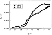
- FIG. 1A is a graph showing the relationship between the charge potential of the positive electrode of the initial product containing the active material and dQ / dV
- FIG. 1B is a graph showing the relationship between the charge potential of the positive electrode of the deteriorated product and dQ / dV.
- the abscissa represents the potential (VvsLi / Li + : Li / Li + potential based on the equilibrium potential), and the ordinate represents dQ / dV.
- FIG. 2 is a graph showing the transition of the K absorption edge energy of Ni of the active material calculated by X-ray absorption spectroscopy measurement (XAFS measurement) with respect to the charging potential.
- the horizontal axis represents the charging potential E (VvsLi / Li + ), and the vertical axis represents the K absorption edge energy E 0 (eV) of Ni.
- the initial product is indicated by ⁇ and the deteriorated product is indicated by ⁇ .
- LiNi 0.5 Mn 1.5 O 4 exists stably in the region of about 5V.
- a redox reaction due to Ni occurs in the vicinity of 4.9V.
- the curve is flattened in the high potential region and the reaction converges, whereas in the case of the deteriorated product, the reaction proceeds also in the high potential region. Therefore, in the case of a deteriorated product, the potential when charging is suspended, that is, the voltage of the storage element is higher than that of the initial product.
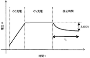
- the internal resistance increases with deterioration, so that the difference (voltage change amount: ⁇ OCV) between the voltage of the power storage element after rest and the voltage when a predetermined period has elapsed gradually increases.
- ⁇ OCV voltage change amount
- the reaction proceeds in a high potential region (high voltage region), and the voltage at rest increases with deterioration. Therefore, the voltage at rest becomes stable and ⁇ OCV gradually decreases despite the increase in internal resistance due to deterioration.
- the deterioration state of the storage element can be estimated easily, quickly, and with high accuracy based on the relationship between ⁇ OCV and SOH.
- FIG. 3 is a block diagram illustrating configurations of the vehicle 1 and the server 13 according to the first embodiment.
- the vehicle 1 includes a battery module 3, a BMU (Battery Management Unit) 4, a load 5, a general ECU (Electronic Control Unit) 6, a communication unit 7, a voltage sensor 8, and a current sensor 9.
- BMU Battery Management Unit
- ECU Electronic Control Unit
- the overall ECU 6 controls the entire power supply device of the vehicle 1.
- the overall ECU 6 also controls the engine when the vehicle 1 is an HEV vehicle or a gasoline vehicle.
- the server 13 includes a communication unit 14 and a control unit 15.
- the overall ECU 6 is connected to the control unit 15 via the communication unit 7, the network 12, and the communication unit 14.
- the overall ECU 6 transmits and receives data to and from the control unit 15 via the network 12.
- any of the BMU 4, the overall ECU 6, and the control unit 15 functions as the estimation device of the present invention.
- the BMU 4 may be a battery ECU.
- the voltage sensor 8 is connected in parallel to the battery module 3 and outputs a detection result corresponding to the overall voltage of the battery module 3.
- the voltage sensor 8 is connected to terminals 23 and 23 (described later) of each battery 2, measures the voltage V 1 between the terminals 23 and 23 of each battery 2, and is a battery that is the total value of V 1 of each battery 2.
- a voltage V between leads 33 and 33 described later of the module 3 is detected.
- the current sensor 9 is connected in series with the battery module 3 and detects the current I flowing through the battery module 3.
- FIG. 4 is a perspective view of the battery module 3.
- the battery module 3 includes a rectangular parallelepiped case 31 and a plurality of the batteries 2 accommodated in the case 31.
- the battery 2 includes a rectangular parallelepiped case main body 21, a cover plate 22, a pair of terminals 23 and 23 provided on the cover plate 22 and having different polarities, a rupture valve 24, and an electrode body 25.
- the electrode body 25 is formed by laminating a positive electrode plate, a separator, and a negative electrode plate, and is accommodated in the case body 21.
- the electrode body 25 may be obtained by winding a positive electrode plate and a negative electrode plate in a flat shape via a separator.
- the positive electrode plate is obtained by forming an active material layer on a positive electrode substrate foil which is a plate-like (sheet-like) or long strip-like metal foil made of aluminum, an aluminum alloy or the like.
- the negative electrode plate is obtained by forming an active material layer on a negative electrode base foil that is a plate-like (sheet-like) or long strip-like metal foil made of copper, a copper alloy, or the like.
- the separator is a microporous sheet made of a synthetic resin.
- LiMeO 2 -Li 2 MnO 3 solid solution As the positive electrode active material, in addition to LiMeO 2 -Li 2 MnO 3 solid solution described above, Li 2 O-LiMeO 2 solid solution, Li 3 NbO 4 -LiMeO 2 solid solution, Li 4 WO 5 -LiMeO 2 solid solution, Li 4 TeO 5 - LiMeO 2 solid solution, Li 3 SbO 4 -LiFeO 2 solid solution, Li 2 RuO 3 -LiMeO 2 solid solution, and a Li-excess active material such as Li 2 RuO 3 -Li 2 MeO 3 solid solution.
- the negative electrode active material examples include metals or alloys such as hard carbon, Si, Sn, Cd, Zn, Al, Bi, Pb, Ge, and Ag, or chalcogenides containing these.
- An example of a chalcogenide is SiO.
- the technique of the present invention is applicable when at least one of these positive electrode active materials and negative electrode active materials has hysteresis.
- Li 2 O, Li 2 O doped with a transition metal element, a lithium transition metal oxide, a lithium transition metal oxide having a reverse fluorite structure, and a reverse fluorite structure A material obtained by mixing a lithium transition metal oxide with a lithium typical element oxide can be given.
- lithium-transition metal oxides doped with transition metal elements Li 2 O material doped with Co to Li 2 O, lithium transition metal oxides having an inverse fluorite structure, Li 6 CoO 4, reverse firefly
- a material in which a lithium transition metal oxide having a stone structure is mixed with a lithium typical element oxide a solid solution or a mixed material of Li 6 CoO 4 and Li 5 AlO 4 can be given.
- Co is preferable as the above-mentioned transition metal, a plurality of other transition metals may be included.
- Al is preferable as the above-mentioned typical element, but a plurality of other typical elements may be included.
- Adjacent terminals 23 of adjacent batteries 2 of the battery module 3 have different polarities, and the terminals 23 are electrically connected to each other by a bus bar 32 so that a plurality of batteries 2 are connected in series. Leads 33 and 33 for taking out electric power are provided at terminals 23 and 23 having opposite polarities of the battery 2 at both ends of the battery module 3.
- FIG. 5 is a block diagram showing the configuration of the BMU 4.
- the BMU 4 includes a control unit 41, a storage unit 42, an input unit 46, and an interface unit 47. These units are connected to each other via a bus so as to communicate with each other.
- the input unit 46 accepts input of detection results from the voltage sensor 8 and the current sensor 9.
- the interface unit 47 includes, for example, a LAN interface and a USB interface, and communicates with other devices such as the overall ECU 6 by wire or wireless.
- the storage unit 42 is configured by a hard disk drive (HDD), for example, and stores various programs and data.
- the storage unit 42 stores, for example, an estimation program 43 for executing a degradation state estimation process described later.
- the estimation program 43 is provided in a state stored in a computer-readable recording medium 50 such as a CD-ROM, DVD-ROM, or USB memory, and is stored in the storage unit 42 by being installed in the BMU 4.
- the estimation program 43 may be acquired from an external computer (not shown) connected to the communication network and stored in the storage unit 42.
- the storage unit 42 also stores estimation information 44 indicating the relationship between the number of cycles and ⁇ OCV, which is obtained in advance for each of a plurality of charging rates through experiments.
- the estimation information 44 may be appropriately updated by a regular method. Instead of the estimation information 44, a function formula may be stored. As the estimation information 44, the relationship between ⁇ OCV and SOH may also be stored. In addition, the information 44 for estimation is not limited to memorize
- the storage unit 42 also stores charge / discharge history data 45.
- the charge / discharge history is an operation history of the battery module 3, information indicating a period (use period) in which the battery module 3 is charged or discharged, information on charge or discharge performed by the battery module 3 in the use period, and the like. It is information including.
- the information indicating the usage period of the battery module 3 is information including information indicating a point in time when the battery module 3 is charged or discharged, an accumulated usage period during which the battery module 3 is used, and the like.
- the information related to charging or discharging performed by the battery module 3 is information indicating a voltage, a rate, and the like at the time of charging or discharging performed by the battery module 3.
- the control unit 41 includes, for example, a CPU, a ROM, a RAM, and the like, and controls the operation of the BMU 4 by executing a computer program such as the estimation program 43 read from the storage unit 42.
- the control unit 41 functions as a processing unit that executes the estimation process of the deterioration state by reading and executing the estimation program 43.
- FIG. 6 is an explanatory diagram for explaining a method of charging the battery module 3.
- the control unit 41 of the BMU 4 performs CC charge with a constant current until the voltage reaches an upper limit voltage such as a full charge voltage, and then performs CV charge with a constant voltage.
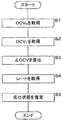
- FIG. 7 is a flowchart illustrating the procedure of the degradation state estimation process performed by the control unit 41.
- the control unit 41 obtains the charge rate from the history data 45 (S4).
- the control unit 41 estimates the deterioration state (S5).
- the control unit 41 reads the relationship between the number of cycles and ⁇ OCV or the function expression according to the charge rate from the estimation information 44 in the storage unit 42. When the relationship corresponding to the rate at the time of charging is not stored as the estimation information 44, the control unit 41 obtains the relationship by interpolation calculation.
- the control unit 41 considers the usage status of the battery module 3, the usage conditions, the deterioration criteria input from the user, etc., and refers to the read estimation information 44 based on the calculated ⁇ OCV.
- the deterioration state of the battery module 3 is estimated, and the process ends.
- the control unit 41 may estimate the deterioration state based on the above-described relationship between ⁇ OCV and SOH. According to the present embodiment, the deterioration state of the power storage element can be estimated well based on the decrease in ⁇ OCV.
- the control unit 41 reads the threshold value of ⁇ OCV corresponding to the charging rate from the estimation information 44, and estimates whether the calculated ⁇ OCV is equal to or less than the threshold value. When it is estimated that the calculated ⁇ OCV is equal to or less than the threshold value, the control unit 41 estimates that the battery module 3 is in a deteriorated state.
- the relationship between the number of cycles and ⁇ OCV / t x is stored in the storage unit 42 as the estimation information 44.
- a functional expression may be stored instead of the relationship.
- the estimation information 44 the relationship between ⁇ OCV / t x and SOH may also be stored.
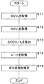
- FIG. 8 is a flowchart illustrating a procedure of deterioration estimation processing by the control unit 41.
- the control unit 41 acquires the charge rate from the history data 45 (S14).
- the control unit 41 estimates the deterioration state (S15).
- the control unit 41 reads out the estimation information 44 corresponding to the charging rate from the storage unit 42. Based on the calculated ⁇ OCV / t x , the control unit 41 refers to the read estimation information 44 in consideration of the usage status of the battery module 3, the usage conditions, and the deterioration criteria input from the user. Thus, it is estimated whether or not the current battery module 3 is in a deteriorated state, and the process ends.
- the control unit 41 may estimate the deterioration state based on the relationship between ⁇ OCV / t x and SOH. According to the present embodiment, the deterioration state of the power storage element can be estimated well based on the decrease in ⁇ OCV / t x .
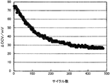
- Example 1 The battery 2 of Example 1 was produced using the above Li-excess type active material as the positive electrode active material and graphite as the negative electrode active material, and the battery module 3 was configured. The battery module 3 was used to perform a charge / discharge cycle test, and the relationship between the number of cycles and ⁇ OCV was determined. The result is shown in FIG. The horizontal axis represents the number of cycles, and the vertical axis represents ⁇ OCV (mV). In the charge / discharge cycle test, CC charging was performed until the voltage reached 4.6V at 0.5C under a temperature of 25 ° C, and CV charging was performed until the current reached 0.1C at 4.6V.
- ⁇ OCV decreases as the number of cycles increases. Therefore, for example, by associating the degree of decrease in ⁇ OCV with SOH, the deterioration state can be estimated based on ⁇ OCV at the time of acquisition. Although it depends on the energization current and temperature, for example, when ⁇ OCV is 1 ⁇ 2 of the initial value, it can be determined that the SOH of the battery 2 has fallen below a certain standard.
- the control unit 41 With reference to the estimation information 44, it is estimated whether or not the battery module 3 is in a deteriorated state.
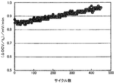
- FIG. 10 is a graph showing the results of determining the relationship between the number of cycles and ⁇ OCV / t x .
- the horizontal axis represents the number of cycles, and the vertical axis represents ⁇ OCV / t x and (mV / min).
- t x is 10 minutes, and in each cycle, the amount of change in OCV per minute ( ⁇ OCV / t x ) is obtained by dividing the above ⁇ OCV when resting for 10 minutes after completion of charging by 10 Seeking.
- ⁇ OCV / t x decreases as the number of cycles increases. Therefore, by associating the degree of decrease of ⁇ OCV / t x with SOH, the deterioration state can be estimated based on ⁇ OCV / t x at the time of acquisition.
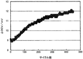
- Comparative Example 1 A battery of Comparative Example 1 was fabricated using NCM111 (Ni: Co: Mn (molar ratio) of 1: 1: 1) as the positive electrode active material and graphite as the negative electrode active material, to form a battery module. A charge / discharge cycle test was performed using this battery module, and the relationship between the number of cycles and ⁇ OCV was determined. The result is shown in FIG. The horizontal axis represents the number of cycles, and the vertical axis represents ⁇ OCV (mV). In the charge / discharge cycle test, CC charge was performed at a temperature of 25 ° C. until the voltage reached 4.2 V at 1.0 C, and rested for 10 minutes.
- FIG. 11 shows that ⁇ OCV increases as the number of cycles increases. As the battery deteriorates, the internal resistance increases, the amount of voltage decrease after the end of charging increases, and ⁇ OCV increases.
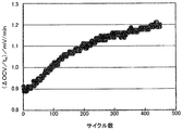
- FIG. 12 is a graph showing the results of determining the relationship between the number of cycles and ⁇ OCV / t x .
- the horizontal axis represents the number of cycles, and the vertical axis represents ⁇ OCV / t x (mV / min).
- t x is 10 minutes, and in each cycle, the amount of change in OCV per minute ( ⁇ OCV / t x ) is obtained by dividing the above ⁇ OCV when resting for 10 minutes after completion of charging by 10 Seeking.
- ⁇ OCV / t x increases as the number of cycles increases.
- Comparative Example 2 A battery of Comparative Example 2 was fabricated using NCM622 (Ni: Co: Mn (molar ratio) of 6: 2: 2) as the positive electrode active material and graphite as the negative electrode active material, and a battery module was configured. A charge / discharge cycle test was conducted using this battery, and the relationship between the number of cycles and ⁇ OCV was determined. The result is shown in FIG. The horizontal axis represents the number of cycles, and the vertical axis represents ⁇ OCV (mV). The charge / discharge program of the charge / discharge cycle test of Comparative Example 2 is the same as the charge / discharge program of the charge / discharge cycle test of Comparative Example 1. FIG. 13 shows that ⁇ OCV increases as the number of cycles increases.
- FIG. 14 is a graph showing the results of determining the relationship between the number of cycles and ⁇ OCV / t x .
- the horizontal axis represents the number of cycles, and the vertical axis represents ⁇ OCV / t x (mV / min).
- t x is 10 minutes, and in each cycle, the amount of change in OCV per minute ( ⁇ OCV / t x ) is obtained by dividing the above ⁇ OCV when resting for 10 minutes after completion of charging by 10 Seeking.
- ⁇ OCV / t x increases as the number of cycles increases.
- charging is performed until a voltage of 4.5 V or higher is reached.
- ⁇ OCV or ⁇ OCV / t x changes characteristically.
- the deterioration state can be estimated easily and quickly at the start of use based on ⁇ OCV, which is highly convenient. Moreover, it can pause for a short time after charge and can estimate a deterioration state. Since the deterioration state can be accurately estimated, control for suppressing the deterioration can be performed at an appropriate timing, and the life of the battery module 3 can be extended.
- the deterioration state can be estimated within the range of normal use conditions, and the battery module 3 does not deteriorate when the deterioration state is estimated.
- the estimation device is not limited to being mounted on a vehicle, but can also be applied to other power storage devices such as a railway regenerative power storage device and a solar power generation system.
- the estimation apparatus according to the present invention can also be applied to mobile devices such as notebook computers, mobile phones, and shavers.
- an electrical storage element is not limited to a lithium ion secondary battery.
- the storage element may be another secondary battery, a primary battery, or an electrochemical cell such as a capacitor.
- ⁇ OCV or ⁇ OCV / t x may be acquired for each battery 2 and the deterioration state of the battery 2 may be estimated separately.
- the present invention can be applied to estimation of a deterioration state of a storage element such as a lithium ion secondary battery.
Landscapes
- Engineering & Computer Science (AREA)
- Manufacturing & Machinery (AREA)
- Chemical & Material Sciences (AREA)
- Chemical Kinetics & Catalysis (AREA)
- Electrochemistry (AREA)
- General Chemical & Material Sciences (AREA)
- Physics & Mathematics (AREA)
- General Physics & Mathematics (AREA)
- Power Engineering (AREA)
- Secondary Cells (AREA)
- Tests Of Electric Status Of Batteries (AREA)
- Charge And Discharge Circuits For Batteries Or The Like (AREA)
Applications Claiming Priority (2)
| Application Number | Priority Date | Filing Date | Title |
|---|---|---|---|
| JP2018113983 | 2018-06-14 | ||
| JP2018-113983 | 2018-06-14 |
Publications (1)
| Publication Number | Publication Date |
|---|---|
| WO2019240225A1 true WO2019240225A1 (ja) | 2019-12-19 |
Family
ID=68842828
Family Applications (1)
| Application Number | Title | Priority Date | Filing Date |
|---|---|---|---|
| PCT/JP2019/023502 Ceased WO2019240225A1 (ja) | 2018-06-14 | 2019-06-13 | 推定装置、蓄電装置、推定方法、及びコンピュータプログラム |
Country Status (2)
| Country | Link |
|---|---|
| JP (1) | JP7322529B2 (enExample) |
| WO (1) | WO2019240225A1 (enExample) |
Cited By (4)
| Publication number | Priority date | Publication date | Assignee | Title |
|---|---|---|---|---|
| WO2022024235A1 (ja) * | 2020-07-29 | 2022-02-03 | 株式会社日立ハイテク | 電池管理装置、電池管理方法 |
| WO2022034671A1 (ja) * | 2020-08-13 | 2022-02-17 | TeraWatt Technology株式会社 | 劣化状態推定装置、劣化状態推定方法、及びプログラム、並びにこれらを搭載したアノードフリーリチウム電池用電源装置 |
| TWI776434B (zh) * | 2021-03-23 | 2022-09-01 | 加百裕工業股份有限公司 | 電池健康狀態檢測系統及方法 |
| EP4266069A4 (en) * | 2021-11-22 | 2024-09-11 | LG Energy Solution, Ltd. | METHOD FOR ESTIMATING THE STATE OF HEALTH OF LITHIUM-SULFUR BATTERY |
Families Citing this family (3)
| Publication number | Priority date | Publication date | Assignee | Title |
|---|---|---|---|---|
| JP7521907B2 (ja) * | 2020-03-06 | 2024-07-24 | 本田技研工業株式会社 | 二次電池の診断装置 |
| CN112946509A (zh) * | 2021-02-26 | 2021-06-11 | 同济大学 | 一种基于电极应变的锂离子电池老化状态估计方法 |
| JP7393822B1 (ja) | 2022-07-29 | 2023-12-07 | 株式会社スリーダムアライアンス | リチウム二次電池の劣化判定方法、電池劣化判定装置 |
Citations (3)
| Publication number | Priority date | Publication date | Assignee | Title |
|---|---|---|---|---|
| JP2013160582A (ja) * | 2012-02-03 | 2013-08-19 | Ntt Facilities Inc | 組電池システムおよび組電池システムの管理方法 |
| JP2014167450A (ja) * | 2013-02-28 | 2014-09-11 | Asahi Kasei Corp | 二次電池の電池状態推定装置及び電池パックの製造方法並びにセルバランス確認方法 |
| JP2015094710A (ja) * | 2013-11-13 | 2015-05-18 | カルソニックカンセイ株式会社 | バッテリの健全度推定装置及び健全度推定方法 |
Family Cites Families (3)
| Publication number | Priority date | Publication date | Assignee | Title |
|---|---|---|---|---|
| JP3371146B2 (ja) * | 1992-08-18 | 2003-01-27 | ソニー株式会社 | バッテリとバッテリ課金方法 |
| JP2014132243A (ja) | 2013-01-07 | 2014-07-17 | Toshiba Corp | 二次電池装置、二次電池装置の残容量測定方法及びプログラム |
| JP6626356B2 (ja) | 2015-03-18 | 2019-12-25 | 積水化学工業株式会社 | 二次電池劣化検出システム、二次電池劣化検出方法 |
-
2019
- 2019-06-11 JP JP2019108908A patent/JP7322529B2/ja active Active
- 2019-06-13 WO PCT/JP2019/023502 patent/WO2019240225A1/ja not_active Ceased
Patent Citations (3)
| Publication number | Priority date | Publication date | Assignee | Title |
|---|---|---|---|---|
| JP2013160582A (ja) * | 2012-02-03 | 2013-08-19 | Ntt Facilities Inc | 組電池システムおよび組電池システムの管理方法 |
| JP2014167450A (ja) * | 2013-02-28 | 2014-09-11 | Asahi Kasei Corp | 二次電池の電池状態推定装置及び電池パックの製造方法並びにセルバランス確認方法 |
| JP2015094710A (ja) * | 2013-11-13 | 2015-05-18 | カルソニックカンセイ株式会社 | バッテリの健全度推定装置及び健全度推定方法 |
Cited By (8)
| Publication number | Priority date | Publication date | Assignee | Title |
|---|---|---|---|---|
| WO2022024235A1 (ja) * | 2020-07-29 | 2022-02-03 | 株式会社日立ハイテク | 電池管理装置、電池管理方法 |
| JPWO2022024235A1 (enExample) * | 2020-07-29 | 2022-02-03 | ||
| TWI785665B (zh) * | 2020-07-29 | 2022-12-01 | 日商日立全球先端科技股份有限公司 | 電池管理裝置、電池管理方法 |
| JP7390490B2 (ja) | 2020-07-29 | 2023-12-01 | 株式会社日立ハイテク | 電池管理装置、電池管理方法 |
| WO2022034671A1 (ja) * | 2020-08-13 | 2022-02-17 | TeraWatt Technology株式会社 | 劣化状態推定装置、劣化状態推定方法、及びプログラム、並びにこれらを搭載したアノードフリーリチウム電池用電源装置 |
| JPWO2022034671A1 (enExample) * | 2020-08-13 | 2022-02-17 | ||
| TWI776434B (zh) * | 2021-03-23 | 2022-09-01 | 加百裕工業股份有限公司 | 電池健康狀態檢測系統及方法 |
| EP4266069A4 (en) * | 2021-11-22 | 2024-09-11 | LG Energy Solution, Ltd. | METHOD FOR ESTIMATING THE STATE OF HEALTH OF LITHIUM-SULFUR BATTERY |
Also Published As
| Publication number | Publication date |
|---|---|
| JP7322529B2 (ja) | 2023-08-08 |
| JP2019219389A (ja) | 2019-12-26 |
Similar Documents
| Publication | Publication Date | Title |
|---|---|---|
| JP7322529B2 (ja) | 推定装置、蓄電装置、推定方法、及びコンピュータプログラム | |
| JP7111015B2 (ja) | 推定装置、蓄電装置、推定方法、及びコンピュータプログラム | |
| CN113853706B (zh) | 使用电极的相对劣化程度控制二次电池操作的设备和方法 | |
| JP6021087B2 (ja) | 混合正極材を含む二次電池のためのシステム、混合正極材を含む二次電池の管理装置及び方法 | |
| JP6081584B2 (ja) | 混合正極材を含む二次電池の電圧推定装置及び方法 | |
| US11181584B2 (en) | Storage amount estimation device, energy storage module, storage amount estimation method, and computer program | |
| JP6409208B1 (ja) | 蓄電量推定装置、蓄電モジュール、蓄電量推定方法、及びコンピュータプログラム | |
| JP6443577B2 (ja) | 管理装置、蓄電モジュール、管理方法、及びコンピュータプログラム | |
| JP7115345B2 (ja) | 推定装置、蓄電装置、推定方法、及びコンピュータプログラム | |
| JP2019176637A (ja) | 充電制御装置、蓄電装置、蓄電素子の充電制御方法、及びコンピュータプログラム | |
| JP7131568B2 (ja) | 推定装置、推定方法及びコンピュータプログラム | |
| JP7556287B2 (ja) | 劣化推定装置、劣化推定方法及びコンピュータプログラム | |
| WO2019017411A1 (ja) | 推定装置、蓄電装置、推定方法、及びコンピュータプログラム | |
| JP6406469B1 (ja) | 蓄電量推定装置、蓄電モジュール、蓄電量推定方法、及びコンピュータプログラム | |
| JP6607079B2 (ja) | 蓄電素子状態推定装置及び蓄電素子状態推定方法 | |
| JP2020193823A (ja) | 推定装置、推定方法及びコンピュータプログラム | |
| WO2019017183A1 (ja) | 推定装置、蓄電装置、推定方法、及びコンピュータプログラム | |
| JP2020024935A (ja) | 蓄電システム及びコンピュータプログラム | |
| JP2021058017A (ja) | 推定装置、推定方法及びコンピュータプログラム | |
| WO2018181624A1 (ja) | 蓄電量推定装置、蓄電モジュール、蓄電量推定方法、及びコンピュータプログラム | |
| JP2019175704A (ja) | 充電制御装置、蓄電装置、蓄電素子の充電制御方法、及びコンピュータプログラム | |
| JP6406470B1 (ja) | 管理装置、蓄電モジュール、管理方法、及びコンピュータプログラム | |
| JP7363311B2 (ja) | 制御方法、制御装置、及びコンピュータプログラム | |
| JP7790412B2 (ja) | 制御方法、制御装置、及びコンピュータプログラム | |
| JP7427901B2 (ja) | 異常判定装置、異常判定方法、及びコンピュータプログラム |
Legal Events
| Date | Code | Title | Description |
|---|---|---|---|
| 121 | Ep: the epo has been informed by wipo that ep was designated in this application |
Ref document number: 19819867 Country of ref document: EP Kind code of ref document: A1 |
|
| NENP | Non-entry into the national phase |
Ref country code: DE |
|
| 122 | Ep: pct application non-entry in european phase |
Ref document number: 19819867 Country of ref document: EP Kind code of ref document: A1 |