WO2019240002A1 - Dispositif de commande de véhicule, procédé de commande de véhicule et système de commande de véhicule - Google Patents
Dispositif de commande de véhicule, procédé de commande de véhicule et système de commande de véhicule Download PDFInfo
- Publication number
- WO2019240002A1 WO2019240002A1 PCT/JP2019/022494 JP2019022494W WO2019240002A1 WO 2019240002 A1 WO2019240002 A1 WO 2019240002A1 JP 2019022494 W JP2019022494 W JP 2019022494W WO 2019240002 A1 WO2019240002 A1 WO 2019240002A1
- Authority
- WO
- WIPO (PCT)
- Prior art keywords
- vehicle
- steering
- vehicle control
- control device
- target
- Prior art date
Links
- 238000000034 method Methods 0.000 title claims description 15
- 238000012937 correction Methods 0.000 claims abstract description 29
- 238000001514 detection method Methods 0.000 claims description 9
- 230000006399 behavior Effects 0.000 description 24
- 238000006243 chemical reaction Methods 0.000 description 17
- 230000008859 change Effects 0.000 description 11
- 230000001629 suppression Effects 0.000 description 10
- 230000003247 decreasing effect Effects 0.000 description 8
- 238000010586 diagram Methods 0.000 description 8
- 230000001133 acceleration Effects 0.000 description 7
- 230000007935 neutral effect Effects 0.000 description 7
- 230000008569 process Effects 0.000 description 6
- 208000019901 Anxiety disease Diseases 0.000 description 4
- 230000036506 anxiety Effects 0.000 description 4
- 230000007423 decrease Effects 0.000 description 4
- 238000012545 processing Methods 0.000 description 4
- 238000009987 spinning Methods 0.000 description 4
- 238000013459 approach Methods 0.000 description 3
- 230000006870 function Effects 0.000 description 3
- 230000005484 gravity Effects 0.000 description 2
- 238000012986 modification Methods 0.000 description 2
- 230000004048 modification Effects 0.000 description 2
- 230000005540 biological transmission Effects 0.000 description 1
- 238000002485 combustion reaction Methods 0.000 description 1
- 230000008878 coupling Effects 0.000 description 1
- 238000010168 coupling process Methods 0.000 description 1
- 238000005859 coupling reaction Methods 0.000 description 1
- 230000003111 delayed effect Effects 0.000 description 1
- 230000007246 mechanism Effects 0.000 description 1
- 239000000725 suspension Substances 0.000 description 1
Images


Classifications
-
- B—PERFORMING OPERATIONS; TRANSPORTING
- B60—VEHICLES IN GENERAL
- B60T—VEHICLE BRAKE CONTROL SYSTEMS OR PARTS THEREOF; BRAKE CONTROL SYSTEMS OR PARTS THEREOF, IN GENERAL; ARRANGEMENT OF BRAKING ELEMENTS ON VEHICLES IN GENERAL; PORTABLE DEVICES FOR PREVENTING UNWANTED MOVEMENT OF VEHICLES; VEHICLE MODIFICATIONS TO FACILITATE COOLING OF BRAKES
- B60T7/00—Brake-action initiating means
- B60T7/12—Brake-action initiating means for automatic initiation; for initiation not subject to will of driver or passenger
- B60T7/22—Brake-action initiating means for automatic initiation; for initiation not subject to will of driver or passenger initiated by contact of vehicle, e.g. bumper, with an external object, e.g. another vehicle, or by means of contactless obstacle detectors mounted on the vehicle
-
- B—PERFORMING OPERATIONS; TRANSPORTING
- B60—VEHICLES IN GENERAL
- B60W—CONJOINT CONTROL OF VEHICLE SUB-UNITS OF DIFFERENT TYPE OR DIFFERENT FUNCTION; CONTROL SYSTEMS SPECIALLY ADAPTED FOR HYBRID VEHICLES; ROAD VEHICLE DRIVE CONTROL SYSTEMS FOR PURPOSES NOT RELATED TO THE CONTROL OF A PARTICULAR SUB-UNIT
- B60W30/00—Purposes of road vehicle drive control systems not related to the control of a particular sub-unit, e.g. of systems using conjoint control of vehicle sub-units, or advanced driver assistance systems for ensuring comfort, stability and safety or drive control systems for propelling or retarding the vehicle
- B60W30/18—Propelling the vehicle
- B60W30/18009—Propelling the vehicle related to particular drive situations
- B60W30/18145—Cornering
-
- B—PERFORMING OPERATIONS; TRANSPORTING
- B60—VEHICLES IN GENERAL
- B60T—VEHICLE BRAKE CONTROL SYSTEMS OR PARTS THEREOF; BRAKE CONTROL SYSTEMS OR PARTS THEREOF, IN GENERAL; ARRANGEMENT OF BRAKING ELEMENTS ON VEHICLES IN GENERAL; PORTABLE DEVICES FOR PREVENTING UNWANTED MOVEMENT OF VEHICLES; VEHICLE MODIFICATIONS TO FACILITATE COOLING OF BRAKES
- B60T7/00—Brake-action initiating means
- B60T7/12—Brake-action initiating means for automatic initiation; for initiation not subject to will of driver or passenger
- B60T7/16—Brake-action initiating means for automatic initiation; for initiation not subject to will of driver or passenger operated by remote control, i.e. initiating means not mounted on vehicle
- B60T7/18—Brake-action initiating means for automatic initiation; for initiation not subject to will of driver or passenger operated by remote control, i.e. initiating means not mounted on vehicle operated by wayside apparatus
-
- B—PERFORMING OPERATIONS; TRANSPORTING
- B60—VEHICLES IN GENERAL
- B60T—VEHICLE BRAKE CONTROL SYSTEMS OR PARTS THEREOF; BRAKE CONTROL SYSTEMS OR PARTS THEREOF, IN GENERAL; ARRANGEMENT OF BRAKING ELEMENTS ON VEHICLES IN GENERAL; PORTABLE DEVICES FOR PREVENTING UNWANTED MOVEMENT OF VEHICLES; VEHICLE MODIFICATIONS TO FACILITATE COOLING OF BRAKES
- B60T8/00—Arrangements for adjusting wheel-braking force to meet varying vehicular or ground-surface conditions, e.g. limiting or varying distribution of braking force
- B60T8/17—Using electrical or electronic regulation means to control braking
- B60T8/1755—Brake regulation specially adapted to control the stability of the vehicle, e.g. taking into account yaw rate or transverse acceleration in a curve
- B60T8/17552—Brake regulation specially adapted to control the stability of the vehicle, e.g. taking into account yaw rate or transverse acceleration in a curve responsive to the tire sideslip angle or the vehicle body slip angle
-
- B—PERFORMING OPERATIONS; TRANSPORTING
- B60—VEHICLES IN GENERAL
- B60T—VEHICLE BRAKE CONTROL SYSTEMS OR PARTS THEREOF; BRAKE CONTROL SYSTEMS OR PARTS THEREOF, IN GENERAL; ARRANGEMENT OF BRAKING ELEMENTS ON VEHICLES IN GENERAL; PORTABLE DEVICES FOR PREVENTING UNWANTED MOVEMENT OF VEHICLES; VEHICLE MODIFICATIONS TO FACILITATE COOLING OF BRAKES
- B60T8/00—Arrangements for adjusting wheel-braking force to meet varying vehicular or ground-surface conditions, e.g. limiting or varying distribution of braking force
- B60T8/17—Using electrical or electronic regulation means to control braking
- B60T8/1755—Brake regulation specially adapted to control the stability of the vehicle, e.g. taking into account yaw rate or transverse acceleration in a curve
- B60T8/17555—Brake regulation specially adapted to control the stability of the vehicle, e.g. taking into account yaw rate or transverse acceleration in a curve specially adapted for enhancing driver or passenger comfort, e.g. soft intervention or pre-actuation strategies
-
- B—PERFORMING OPERATIONS; TRANSPORTING
- B60—VEHICLES IN GENERAL
- B60W—CONJOINT CONTROL OF VEHICLE SUB-UNITS OF DIFFERENT TYPE OR DIFFERENT FUNCTION; CONTROL SYSTEMS SPECIALLY ADAPTED FOR HYBRID VEHICLES; ROAD VEHICLE DRIVE CONTROL SYSTEMS FOR PURPOSES NOT RELATED TO THE CONTROL OF A PARTICULAR SUB-UNIT
- B60W10/00—Conjoint control of vehicle sub-units of different type or different function
- B60W10/18—Conjoint control of vehicle sub-units of different type or different function including control of braking systems
- B60W10/184—Conjoint control of vehicle sub-units of different type or different function including control of braking systems with wheel brakes
-
- B—PERFORMING OPERATIONS; TRANSPORTING
- B60—VEHICLES IN GENERAL
- B60W—CONJOINT CONTROL OF VEHICLE SUB-UNITS OF DIFFERENT TYPE OR DIFFERENT FUNCTION; CONTROL SYSTEMS SPECIALLY ADAPTED FOR HYBRID VEHICLES; ROAD VEHICLE DRIVE CONTROL SYSTEMS FOR PURPOSES NOT RELATED TO THE CONTROL OF A PARTICULAR SUB-UNIT
- B60W10/00—Conjoint control of vehicle sub-units of different type or different function
- B60W10/20—Conjoint control of vehicle sub-units of different type or different function including control of steering systems
-
- B—PERFORMING OPERATIONS; TRANSPORTING
- B60—VEHICLES IN GENERAL
- B60W—CONJOINT CONTROL OF VEHICLE SUB-UNITS OF DIFFERENT TYPE OR DIFFERENT FUNCTION; CONTROL SYSTEMS SPECIALLY ADAPTED FOR HYBRID VEHICLES; ROAD VEHICLE DRIVE CONTROL SYSTEMS FOR PURPOSES NOT RELATED TO THE CONTROL OF A PARTICULAR SUB-UNIT
- B60W30/00—Purposes of road vehicle drive control systems not related to the control of a particular sub-unit, e.g. of systems using conjoint control of vehicle sub-units, or advanced driver assistance systems for ensuring comfort, stability and safety or drive control systems for propelling or retarding the vehicle
- B60W30/02—Control of vehicle driving stability
-
- B—PERFORMING OPERATIONS; TRANSPORTING
- B60—VEHICLES IN GENERAL
- B60W—CONJOINT CONTROL OF VEHICLE SUB-UNITS OF DIFFERENT TYPE OR DIFFERENT FUNCTION; CONTROL SYSTEMS SPECIALLY ADAPTED FOR HYBRID VEHICLES; ROAD VEHICLE DRIVE CONTROL SYSTEMS FOR PURPOSES NOT RELATED TO THE CONTROL OF A PARTICULAR SUB-UNIT
- B60W30/00—Purposes of road vehicle drive control systems not related to the control of a particular sub-unit, e.g. of systems using conjoint control of vehicle sub-units, or advanced driver assistance systems for ensuring comfort, stability and safety or drive control systems for propelling or retarding the vehicle
- B60W30/10—Path keeping
- B60W30/12—Lane keeping
-
- B—PERFORMING OPERATIONS; TRANSPORTING
- B60—VEHICLES IN GENERAL
- B60W—CONJOINT CONTROL OF VEHICLE SUB-UNITS OF DIFFERENT TYPE OR DIFFERENT FUNCTION; CONTROL SYSTEMS SPECIALLY ADAPTED FOR HYBRID VEHICLES; ROAD VEHICLE DRIVE CONTROL SYSTEMS FOR PURPOSES NOT RELATED TO THE CONTROL OF A PARTICULAR SUB-UNIT
- B60W30/00—Purposes of road vehicle drive control systems not related to the control of a particular sub-unit, e.g. of systems using conjoint control of vehicle sub-units, or advanced driver assistance systems for ensuring comfort, stability and safety or drive control systems for propelling or retarding the vehicle
- B60W30/18—Propelling the vehicle
- B60W30/18172—Preventing, or responsive to skidding of wheels
-
- B—PERFORMING OPERATIONS; TRANSPORTING
- B60—VEHICLES IN GENERAL
- B60W—CONJOINT CONTROL OF VEHICLE SUB-UNITS OF DIFFERENT TYPE OR DIFFERENT FUNCTION; CONTROL SYSTEMS SPECIALLY ADAPTED FOR HYBRID VEHICLES; ROAD VEHICLE DRIVE CONTROL SYSTEMS FOR PURPOSES NOT RELATED TO THE CONTROL OF A PARTICULAR SUB-UNIT
- B60W40/00—Estimation or calculation of non-directly measurable driving parameters for road vehicle drive control systems not related to the control of a particular sub unit, e.g. by using mathematical models
- B60W40/10—Estimation or calculation of non-directly measurable driving parameters for road vehicle drive control systems not related to the control of a particular sub unit, e.g. by using mathematical models related to vehicle motion
- B60W40/103—Side slip angle of vehicle body
-
- B—PERFORMING OPERATIONS; TRANSPORTING
- B62—LAND VEHICLES FOR TRAVELLING OTHERWISE THAN ON RAILS
- B62D—MOTOR VEHICLES; TRAILERS
- B62D6/00—Arrangements for automatically controlling steering depending on driving conditions sensed and responded to, e.g. control circuits
- B62D6/002—Arrangements for automatically controlling steering depending on driving conditions sensed and responded to, e.g. control circuits computing target steering angles for front or rear wheels
- B62D6/003—Arrangements for automatically controlling steering depending on driving conditions sensed and responded to, e.g. control circuits computing target steering angles for front or rear wheels in order to control vehicle yaw movement, i.e. around a vertical axis
-
- B—PERFORMING OPERATIONS; TRANSPORTING
- B60—VEHICLES IN GENERAL
- B60T—VEHICLE BRAKE CONTROL SYSTEMS OR PARTS THEREOF; BRAKE CONTROL SYSTEMS OR PARTS THEREOF, IN GENERAL; ARRANGEMENT OF BRAKING ELEMENTS ON VEHICLES IN GENERAL; PORTABLE DEVICES FOR PREVENTING UNWANTED MOVEMENT OF VEHICLES; VEHICLE MODIFICATIONS TO FACILITATE COOLING OF BRAKES
- B60T2201/00—Particular use of vehicle brake systems; Special systems using also the brakes; Special software modules within the brake system controller
- B60T2201/08—Lane monitoring; Lane Keeping Systems
-
- B—PERFORMING OPERATIONS; TRANSPORTING
- B60—VEHICLES IN GENERAL
- B60T—VEHICLE BRAKE CONTROL SYSTEMS OR PARTS THEREOF; BRAKE CONTROL SYSTEMS OR PARTS THEREOF, IN GENERAL; ARRANGEMENT OF BRAKING ELEMENTS ON VEHICLES IN GENERAL; PORTABLE DEVICES FOR PREVENTING UNWANTED MOVEMENT OF VEHICLES; VEHICLE MODIFICATIONS TO FACILITATE COOLING OF BRAKES
- B60T2260/00—Interaction of vehicle brake system with other systems
- B60T2260/02—Active Steering, Steer-by-Wire
-
- B—PERFORMING OPERATIONS; TRANSPORTING
- B60—VEHICLES IN GENERAL
- B60W—CONJOINT CONTROL OF VEHICLE SUB-UNITS OF DIFFERENT TYPE OR DIFFERENT FUNCTION; CONTROL SYSTEMS SPECIALLY ADAPTED FOR HYBRID VEHICLES; ROAD VEHICLE DRIVE CONTROL SYSTEMS FOR PURPOSES NOT RELATED TO THE CONTROL OF A PARTICULAR SUB-UNIT
- B60W2520/00—Input parameters relating to overall vehicle dynamics
- B60W2520/10—Longitudinal speed
-
- B—PERFORMING OPERATIONS; TRANSPORTING
- B60—VEHICLES IN GENERAL
- B60W—CONJOINT CONTROL OF VEHICLE SUB-UNITS OF DIFFERENT TYPE OR DIFFERENT FUNCTION; CONTROL SYSTEMS SPECIALLY ADAPTED FOR HYBRID VEHICLES; ROAD VEHICLE DRIVE CONTROL SYSTEMS FOR PURPOSES NOT RELATED TO THE CONTROL OF A PARTICULAR SUB-UNIT
- B60W2520/00—Input parameters relating to overall vehicle dynamics
- B60W2520/20—Sideslip angle
-
- B—PERFORMING OPERATIONS; TRANSPORTING
- B60—VEHICLES IN GENERAL
- B60W—CONJOINT CONTROL OF VEHICLE SUB-UNITS OF DIFFERENT TYPE OR DIFFERENT FUNCTION; CONTROL SYSTEMS SPECIALLY ADAPTED FOR HYBRID VEHICLES; ROAD VEHICLE DRIVE CONTROL SYSTEMS FOR PURPOSES NOT RELATED TO THE CONTROL OF A PARTICULAR SUB-UNIT
- B60W2520/00—Input parameters relating to overall vehicle dynamics
- B60W2520/26—Wheel slip
-
- B—PERFORMING OPERATIONS; TRANSPORTING
- B60—VEHICLES IN GENERAL
- B60W—CONJOINT CONTROL OF VEHICLE SUB-UNITS OF DIFFERENT TYPE OR DIFFERENT FUNCTION; CONTROL SYSTEMS SPECIALLY ADAPTED FOR HYBRID VEHICLES; ROAD VEHICLE DRIVE CONTROL SYSTEMS FOR PURPOSES NOT RELATED TO THE CONTROL OF A PARTICULAR SUB-UNIT
- B60W2552/00—Input parameters relating to infrastructure
- B60W2552/53—Road markings, e.g. lane marker or crosswalk
-
- B—PERFORMING OPERATIONS; TRANSPORTING
- B60—VEHICLES IN GENERAL
- B60W—CONJOINT CONTROL OF VEHICLE SUB-UNITS OF DIFFERENT TYPE OR DIFFERENT FUNCTION; CONTROL SYSTEMS SPECIALLY ADAPTED FOR HYBRID VEHICLES; ROAD VEHICLE DRIVE CONTROL SYSTEMS FOR PURPOSES NOT RELATED TO THE CONTROL OF A PARTICULAR SUB-UNIT
- B60W2710/00—Output or target parameters relating to a particular sub-units
- B60W2710/18—Braking system
- B60W2710/182—Brake pressure, e.g. of fluid or between pad and disc
-
- B—PERFORMING OPERATIONS; TRANSPORTING
- B60—VEHICLES IN GENERAL
- B60W—CONJOINT CONTROL OF VEHICLE SUB-UNITS OF DIFFERENT TYPE OR DIFFERENT FUNCTION; CONTROL SYSTEMS SPECIALLY ADAPTED FOR HYBRID VEHICLES; ROAD VEHICLE DRIVE CONTROL SYSTEMS FOR PURPOSES NOT RELATED TO THE CONTROL OF A PARTICULAR SUB-UNIT
- B60W2710/00—Output or target parameters relating to a particular sub-units
- B60W2710/20—Steering systems
- B60W2710/202—Steering torque
-
- B—PERFORMING OPERATIONS; TRANSPORTING
- B60—VEHICLES IN GENERAL
- B60W—CONJOINT CONTROL OF VEHICLE SUB-UNITS OF DIFFERENT TYPE OR DIFFERENT FUNCTION; CONTROL SYSTEMS SPECIALLY ADAPTED FOR HYBRID VEHICLES; ROAD VEHICLE DRIVE CONTROL SYSTEMS FOR PURPOSES NOT RELATED TO THE CONTROL OF A PARTICULAR SUB-UNIT
- B60W2720/00—Output or target parameters relating to overall vehicle dynamics
- B60W2720/20—Sideslip angle
Definitions
- the present invention relates to a vehicle control device, a vehicle control method, and a vehicle control system, and more particularly, to a technique for guiding a vehicle in a target traveling direction.
- the automatic braking device of Patent Document 1 is an automatic braking device for a vehicle having automatic braking means for applying a braking force to a wheel when an obstacle is detected by the obstacle detecting means, and the automatic braking device is in operation. Means for increasing the steering operation are provided.
- the steering torque is increased in order to suppress erroneous steering by the driver. Then, steering torque may be generated in a direction different from the driver's intention.
- the driver may feel that the vehicle is not moving as intended and may have anxiety.
- the steering torque for guiding in the target traveling direction is weakened, convergence to the target steering steering angle is delayed and the vehicle may be guided in the target traveling direction. It can be difficult.
- a steer-by-wire steering system that separates the tire steering angle control and the steering steering angle control by separating the mechanical coupling between the tire steering angle and the steering steering angle that determines the traveling direction of the vehicle, It is possible to guide the traveling direction of the vehicle to the target traveling direction without changing the steering torque.
- the steer-by-wire steering system has a problem that the system becomes complicated and expensive.
- An object of the present invention is to provide a vehicle control device, a vehicle control method, and a vehicle control system that can accurately guide in a target traveling direction while giving a steering torque without anxiety to a driver with a simple configuration. It is in.
- the vehicle control device, the vehicle control method, and the vehicle control system are obtained based on information related to a travel route of the vehicle and a physical quantity related to a motion state of the vehicle.
- the vehicle body slip angle obtained based on the physical quantity related to the motion state of the vehicle is output to the braking / driving controller for controlling the braking / driving actuator of the vehicle.
- a signal related to the steering correction torque for correcting the steering torque according to the behavior of the vehicle, which is obtained based on the target braking / driving force is output to the steering force controller that controls the steering actuator of the vehicle. I made it.
- guidance in the target traveling direction of the vehicle is performed by controlling the braking / driving force, while the steering torque is corrected according to the behavior of the vehicle, so that the driver can feel the steering without anxiety.
- Guidance in the target traveling direction can be performed with high accuracy while applying torque.
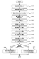
- 1 is an overall configuration diagram of a vehicle control system. It is a flowchart which shows the calculation process of the target braking / driving force, the gain of a steering torque, and a base point steering angle. It is a flowchart which shows the calculation process of the target braking / driving force, the gain of a steering torque, and a base point steering angle. It is a diagram which shows the correlation with a front wheel slip angle (steering angle) and steering torque. It is a diagram showing the correlation between the front wheel slip angle (steering angle) and the steering torque for explaining the shift processing of the base steering angle. It is a diagram for demonstrating the gain setting of a steering torque. It is a diagram for explaining a gain setting of the steering torque for achieving the convergence of the spin.
- FIG. 1 is a block diagram illustrating an aspect of a vehicle control system.
- the vehicle control system 10 in FIG. 1 includes a vehicle control device 20, a braking / driving controller 30, and a steering force controller 40.
- the vehicle control device 20, the braking / driving controller 30, and the steering force controller 40 are electronic control devices including a microcomputer having a CPU (Central Processing Unit), a ROM (Read Only Memory), a RAM (Random Access Memory), and the like.
- the vehicle control device 20 transmits various command signals for driving support to the braking / driving controller 30 and the steering force controller 40.
- a vehicle 50 equipped with the vehicle control system 10 includes a braking device 51 such as a hydraulic brake system capable of electronically controlling braking force for each wheel, a power device 52 such as an internal combustion engine capable of electronically controlling output torque, and steering torque.
- An electric power steering device 53 as an aspect of a power steering device capable of electronic control of (steering force) is provided.
- the electric power steering device 53 is a mechanism that steers the front wheels, which are steered wheels, in accordance with the rotation of the steering wheel, and includes a steering actuator that includes a motor 53A that generates assist torque that assists the steering operation by the driver. It is.
- the braking / driving controller 30 includes, as software, a function of controlling the braking device 51 and the power device 52, in other words, the braking / driving actuator. Further, the steering force controller 40 has a function of controlling the electric power steering device 53, in other words, a steering actuator, as software.
- the steering force controller 40 generates a target steering torque from the steering angle and controls the assist torque (motor torque) output by the electric power steering device 53 so that the actual steering torque approaches the target steering torque.
- the target steering torque generated based on the steering angle is basically zero at the neutral position, and is set to a larger torque as the left steering angle and the right steering angle increase from the neutral position. .
- the vehicle 50 uses a camera, radar, GPS (Global Positioning System) and map information together to recognize the travel route of the vehicle 50, in other words, course information such as curve curvature and obstacles.
- a recognition sensor 60 is provided.
- the vehicle 50 includes a vehicle motion state detection sensor 70 that detects various physical quantities related to the motion state of the vehicle 50.
- the vehicle motion state detection sensor 70 includes, for example, a yaw rate sensor and an acceleration sensor.
- the vehicle control device 20 which is an aspect of the vehicle control device, includes information on the travel route of the vehicle 50 sent from the external recognition sensor 60, and the motion state of the vehicle 50 such as yaw rate and acceleration sent from the vehicle motion state detection sensor 70. Is input, and further information on the steering angle of the electric power steering device 53 is input.
- the vehicle control device 20 calculates a target braking / driving force for guiding the vehicle 50 in the target traveling direction based on the various signals and information input, and corrects the steering torque according to the vehicle behavior. The steering correction torque is calculated.
- the vehicle control device 20 determines the steering correction torque as a steering torque gain and a base steering angle, as will be described later. That is, the vehicle control device 20 corrects the steering torque (steering force) by changing the gain of the steering torque and the base steering angle according to the vehicle behavior.
- the vehicle control device 20 sends a signal related to the target braking / driving force to the braking / driving controller 30, and sends a signal related to the gain of the steering torque and the base steering angle, that is, a signal related to the steering correction torque, to the steering force controller 40.
- the braking / driving controller 30 controls the braking / driving force of each wheel based on the target braking / driving force sent from the vehicle control device 20. Further, the steering force controller 40 changes the generation characteristic of the target steering torque according to the steering angle based on the gain of the steering torque and the base steering angle sent from the vehicle control device 20, and based on the changed characteristic. The assist torque is controlled based on the generated target steering torque.
- the vehicle control device 20 calculates a target braking / driving force, a gain of steering torque, and a base steering angle, a course trace moment calculating unit 21, a vehicle body slip angle calculating unit 22, a front and rear wheel slip angle calculating unit 23, a front wheel Slip angle steering angle conversion value calculation unit 24, spin suppression moment calculation unit 25, vehicle target behavior calculation unit 26, each wheel generation target braking / driving force calculation unit 27, steering torque gain calculation unit 28, base steering angle calculation unit 29
- the function to perform is provided as software.
- the course trace moment calculating unit 21 determines the road ahead of which the vehicle 50 travels based on the current position of the vehicle 50 identified based on the information sent from the external recognition sensor 60, road route information scheduled to travel in advance, and the like. A curve curvature is calculated, and a moment required to be applied to the vehicle 50 in order to trace the calculated curve curvature is calculated.
- the vehicle body slip angle calculation unit 22 calculates the vehicle body slip angle ⁇ s based on the yaw rate, lateral acceleration, and the like sent from the vehicle motion state detection sensor 70.
- the front and rear wheel slip angle calculation unit 23 calculates the front wheel slip angle ⁇ f and the rear wheel slip angle ⁇ r based on the vehicle body slip angle ⁇ s calculated by the vehicle body slip angle calculation unit 22, and further, the front wheel steering angle ⁇ , the yaw rate, the vehicle speed, and the like. To do.
- the front wheel slip angle steering angle conversion value calculation unit 24 uses the front wheel slip angle ⁇ f calculated by the front and rear wheel slip angle calculation unit 23 based on the correlation between the steering steering angle inherent to the vehicle 50 and the tire turning angle as the steering angle of the front wheels. Convert to.
- the spin suppression moment calculation unit 25 calculates a moment that needs to be applied to the vehicle 50 in order to suppress an excessive yaw moment generated in the vehicle 50 based on the change rate of the yaw rate.
- the vehicle target behavior calculation unit 26 is a moment (course trace moment) for course tracing calculated by the course trace moment calculation unit 21 and a moment for suppressing an excessive yaw moment calculated by the spin suppression moment calculation unit 25 ( The final moment to be applied to the vehicle 50 is calculated based on the spin suppression moment).
- the vehicle target behavior calculation unit 26 can calculate the sum of the moment for the course tracing and the moment for suppressing the excessive yaw moment as the final moment to be given to the vehicle 50. . Further, the vehicle target behavior calculation unit 26 can calculate the larger one of the moment for the course tracing and the moment for suppressing the excessive yaw moment as the final moment to be given to the vehicle 50. it can.
- Each wheel generation target braking / driving force calculating unit 27 calculates the braking / driving force (target braking / driving force) of each wheel necessary to give the vehicle 50 the moment calculated by the vehicle target behavior calculating unit 26. That is, the vehicle control device 20 performs driving support for guiding the vehicle 50 in the target traveling direction by adjusting the moment applied to the vehicle 50 by controlling the braking / driving force of each wheel.
- the steering torque gain calculation unit 28 calculates the vehicle body slip angle ⁇ s calculated by the vehicle body slip angle calculation unit 22, the front wheel slip angle steering angle conversion value calculated by the front wheel slip angle steering angle conversion value calculation unit 24, and the wheel generation target control. Based on the target braking / driving force of each wheel calculated by the driving force calculation unit 27, a gain of the steering torque is calculated. That is, the vehicle control device 20 changes the target steering torque with respect to the steering angle by changing the gain instructed to the steering force controller 40.
- the steering torque gain is a command for increasing or decreasing the target steering torque with respect to the steering angle.
- the target steering torque correction coefficient, the target steering torque shift amount, or the target steering torque map (calculation formula) It may be a selection signal or the like.
- the base steering angle calculation unit 29 converts the front wheel slip angle steering angle conversion value calculated by the front wheel slip angle steering angle conversion value calculation unit 24 and the target braking / driving force of each wheel calculated by each wheel generation target braking / driving force calculation unit 27. Based on the above, the base steering angle, which is the steering angle that makes the steering torque zero, is calculated.
- the vehicle control device 20 can change the steering angle returned by the steering reaction force by changing the base steering angle, and can guide steering by the driver in a direction in which the vehicle behavior is stabilized by setting the base steering angle. It becomes possible. Then, the vehicle control device 20 transmits the steering torque gain calculated by the steering torque gain calculation unit 28 and a signal related to the base steering angle calculated by the base steering angle calculation unit 29 to the steering force controller 40, and each wheel generation target control is transmitted. A signal related to the target braking / driving force of each wheel calculated by the driving force calculation unit 27 is transmitted to the braking / driving controller 30.
- step S110 the vehicle control device 20 receives information on the travel route of the vehicle 50 sent from the external recognition sensor 60, that is, information on a road surface and an obstacle that can be traveled.
- the vehicle control device 20 receives vehicle behavior information such as yaw rate, longitudinal acceleration, and lateral acceleration sent from the vehicle motion state detection sensor 70 in step S120.
- vehicle behavior information such as yaw rate, longitudinal acceleration, and lateral acceleration sent from the vehicle motion state detection sensor 70 in step S120.
- the vehicle control device 20 obtains the current position and the target traveling direction of the vehicle 50 based on information related to the travel route of the vehicle 50.
- the vehicle control device 20 roughly obtains the current position of the vehicle 50 by GPS, and recognizes where the vehicle 50 exists on the road map. Further, the vehicle control device 20 recognizes a white line on the road surface from a photographed image in front of the vehicle by the camera to obtain a position on the road of the vehicle 50, thereby determining the current position of the vehicle 50 and the target traveling direction. Ask.
- step S140 the vehicle control device 20 recognizes the route on which the vehicle 50 is to travel based on the current position of the vehicle 50, the target traveling direction, information on the road map, and the like, and the travel route ( The curve curvature (road curvature) of the course) is calculated. Further, the vehicle control device 20 calculates the vehicle body slip angle ⁇ s in step S150.
- the vehicle control device 20 calculates the vehicle body slip angle ⁇ s by integrating the difference between the yaw rate and the lateral acceleration according to Equation 1.
- ⁇ s is the vehicle body slip angle
- Yg is the lateral acceleration
- Vx is the vehicle longitudinal speed (vehicle speed)
- d ⁇ / dt is the yaw rate.
- step S160 the vehicle control device 20 calculates the front wheel slip angle ⁇ f and the rear wheel slip angle ⁇ r based on the vehicle body slip angle ⁇ s, the front wheel steering angle ⁇ , the yaw rate, the vehicle speed, and the like.
- the vehicle control device 20 calculates the front wheel slip angle ⁇ f and the rear wheel slip angle ⁇ r according to Equation 2.
- Equation 2 ⁇ f is the front wheel slip angle
- ⁇ r is the rear wheel slip angle
- Ir is the distance from the rear wheel axis to the center of gravity
- ⁇ is the front wheel steering angle.
- the vehicle control device 20 calculates the vehicle moment M generating the vehicle body slip angle ⁇ s in step S170, for example, according to Equation 3.
- M is a vehicle moment
- I is a vehicle inertia moment
- d2 ⁇ / dt2 is a yaw rate differential value.
- the vehicle control device 20 calculates a course trace moment Mc, which is a moment for turning the curve curvature obtained in step S140, in step S180.
- the vehicle control device 20 calculates the yaw rate d ⁇ c / dt necessary for traveling along the curve curvature according to Equation 4 based on the curve curvature 1 / ⁇ ( ⁇ : turning radius) and the vehicle speed Vx.
- the vehicle control device 20 calculates the course trace moment Mc necessary for setting the current yaw rate d ⁇ / dt to the yaw rate d ⁇ c / dt corresponding to the curve curvature up to the target position according to the equation (5).
- ⁇ t is the time until the vehicle 50 reaches the target position from the current position.
- step S190 the vehicle control device 20 calculates a spin suppression moment Ms that is a moment for correcting the vehicle behavior when the behavior of the vehicle 50 is disturbed.
- the vehicle control device 20 calculates the spin suppression moment Ms according to Equation 6 using, for example, the vehicle body slip angle ⁇ s and the yaw rate differential value d2 ⁇ / dt2 that are indices of the spin state.
- Ks1 is a slip angle gain for moment control
- Ks2 is a yaw rate differential value gain for moment control.
- the vehicle control device 20 calculates a vehicle target moment Mt that is a moment that should finally be generated in the vehicle 50 in step S200.
- the vehicle control device 20 calculates the sum of the course trace moment Mc and the spin suppression moment Ms necessary for making the current yaw rate d ⁇ / dt the yaw rate d ⁇ c / dt corresponding to the curve curvature up to the target position.
- the vehicle control device 20 for example, out of the course trace moment Mc and the spin suppression moment Ms necessary for making the current yaw rate d ⁇ / dt the yaw rate d ⁇ c / dt corresponding to the curve curvature up to the target position.
- the larger one can be the final vehicle target moment Mt (Mt MAX (Mc, Mt)).
- step S220 the vehicle control device 20 compares the vehicle moment M currently generated by the vehicle 50 with the vehicle target moment Mt and changes the vehicle moment M in order to achieve the vehicle target moment Mt. Is in an increasing direction or a decreasing direction.
- the vehicle control device 20 indicates that the signs of the vehicle moment M and the vehicle target moment Mt are opposite, that is, the direction of the vehicle moment M generated by the vehicle 50 at the present time and the vehicle target moment Mt.
- the current direction is opposite, it is determined that the changing direction of the vehicle moment M to achieve the vehicle target moment Mt is a decreasing direction.
- the vehicle control device 20 sets the vehicle moment M for achieving the vehicle target moment Mt when the vehicle moment M and the vehicle target moment Mt have the same sign but the vehicle moment M is larger than the vehicle target moment Mt. It is determined that the changing direction is a decreasing direction. On the other hand, when the signs of the vehicle moment M and the vehicle target moment Mt are the same and the vehicle moment M is smaller than the vehicle target moment Mt, the vehicle control device 20 sets the vehicle moment M for achieving the vehicle target moment Mt. It is determined that the changing direction is an increasing direction.
- step S220 If vehicle control device 20 determines in step S220 that the change direction of vehicle moment M for achieving vehicle target moment Mt is a decreasing direction, the process proceeds from step S220 to step S230.
- the change direction of the vehicle moment M for achieving the vehicle target moment Mt is a decreasing direction, it is appropriate to brake the outer turning wheel to achieve the vehicle target moment Mt.
- the vehicle control device 20 calculates the target value of the braking force applied to the turning outer wheel based on the deviation amount ⁇ M obtained in step S210 in step S230. That is, in step S230, the vehicle control device 20 sets the target value of the braking force applied to the turning outer wheel to achieve the vehicle target moment Mt as the vehicle moment M generated by the vehicle 50 and the vehicle target moment Mt. Is calculated according to the deviation amount ⁇ M.
- the vehicle control device 20 calculates the target braking / driving force TGFx (fl) of the left front wheel fl and the target braking / driving force TGFx (rl) of the left rear wheel rl according to Equation 7 in step S230.
- TGFx ( ⁇ ) is a target braking / driving force of each wheel
- Tr is a left / right tire tread / 2
- Kfx is a weighting factor that determines allocation (distribution) of braking force to the front and rear wheels.
- the vehicle control device 20 can store the weighting coefficient Kfx in the memory as a fixed value, and can variably set it according to the driving situation such as the front and rear wheel weight distribution of the vehicle 50 and the vehicle deceleration. .
- step S220 when determining in step S220 that the change direction of the vehicle moment M for achieving the vehicle target moment Mt is the increasing direction, the vehicle control device 20 proceeds from step S220 to step S240.
- the change direction of the vehicle moment M for achieving the vehicle target moment Mt is an increasing direction, it is reasonable to achieve the vehicle target moment Mt by braking the inner turning wheel, contrary to the decreasing direction. is there.
- the vehicle control device 20 calculates the target value of the braking force applied to the turning inner wheel based on the deviation amount ⁇ M obtained in step S210 in step S240. That is, in step S240, the vehicle control device 20 sets the target value of the braking force applied to the turning inner wheel to achieve the vehicle target moment Mt as the vehicle moment M generated by the vehicle 50 and the vehicle target moment Mt. Is calculated according to the deviation amount ⁇ M.
- the vehicle control device 20 uses the target braking / driving force TGFx ( ⁇ ) for guiding the vehicle 50 in the target traveling direction, the information related to the travel route of the vehicle 50, and the physical quantity related to the motion state of the vehicle 50. Calculate based on
- step S250 the vehicle control device 20 temporarily calculates a base steering angle that is a steering angle at which the steering torque is zero (the steering reaction force is zero). Since the steering torque is corrected by changing the base steering angle, the base steering angle is a signal related to the steering correction torque for correcting the steering torque.
- the provisional base steering angle is a base steering angle changed according to the front wheel slip angle ⁇ f
- the final base steering angle is a base steering angle corresponding to the front wheel slip angle ⁇ f.
- the base steering angle is changed according to the target braking / driving force for guiding the vehicle 50 in the target traveling direction. That is, the vehicle control device 20 obtains the base steering angle that is a signal related to the steering correction torque, based on the front wheel slip angle ⁇ f and the target braking / driving force.
- step S250 the vehicle control device 20 sets the base steering angle to a steering angle at which the front wheel slip angle ⁇ f corresponds to zero.
- the steering force controller 40 is based on the characteristic that a larger target steering torque is generated as the steering steering angle becomes larger from the neutral position, and the steering angle corresponding to the front wheel slip angle ⁇ f being zero is a neutral steering angle.
- the target steering torque is generated with basic characteristics.
- the target steering torque is generated to zero at the base steering angle shifted from the neutral position.
- a larger target steering torque is generated.
- the steering reaction force acts toward the base steering angle that makes the target steering torque zero, so that the driver can steer. It can be guided toward an arbitrary base point steering angle.
- the steering reaction force is approximately proportional to the tire lateral force
- the tire lateral force is approximately proportional to the front wheel tire slip angle.
- the vehicle control device 20 sets the base steering angle at which the steering reaction force becomes zero to a steering angle at which the front wheel slip angle ⁇ f corresponds to zero, and the direction in which the front wheel slip angle ⁇ f becomes zero (in other words, smaller).
- the steering reaction force is applied in the direction) to prompt the driver to perform steering so that the lateral force of the front wheels is zero. That is, the steering angle at which the front wheel slip angle ⁇ f corresponds to zero is a steering angle at which moment generation due to unnecessary front wheel steering during vehicle spin can be made zero, and the vehicle control device 20 corresponds to the front wheel slip angle ⁇ f being zero.
- the steering angle as the base steering angle, the driver's steering can be assisted in a direction in which the vehicle behavior is stabilized.
- the vehicle 50 is guided in the target traveling direction by the braking / driving moment by the braking / driving force instructed by the vehicle controller 20 to the braking / driving controller 30, so that the vehicle 50 travels to the target while suppressing the driver's uncomfortable feeling. It can be guided in the direction.
- Step S230 and Step S240 When the target braking / driving force calculated in Step S230 and Step S240 is applied to the turning outer wheel or the turning inner wheel to give a braking / driving moment for guiding the vehicle 50 in the target traveling direction, a self-steering force is applied to the tire.
- the reaction force applied to the steering is changed by the braking / driving force. For this reason, when the self-steering force due to the braking / driving force for guiding the vehicle 50 in the target traveling direction increases, the steering rudder angle changes in a direction different from the direction intended by the driver, causing the driver to feel uncomfortable. There is a possibility to make it.
- the vehicle control device 20 sets a steering correction torque for suppressing changes in the steering angle due to self-steering in steps S260 to S290.
- step S260 the vehicle control device 20 calculates a self-steering force based on the target braking / driving force TGFx ( ⁇ ) calculated in step S230 or step S240.
- the self-steering force is determined by the suspension geometry of the vehicle 50, is approximately proportional to the braking force, and acts in the opposite direction from side to side. Therefore, the vehicle control device 20 calculates the self-steering force by multiplying the target braking / driving forces TGFx (fl) and TGFx (fr) of the front wheels by a gain specific to the vehicle, as shown in Equation 8.
- F_ss is a self-steering force
- Kfxst is a calculated gain of the self-steering force F_ss.
- step S270 obtains the target steering torque SFp at the current steering angle from the steering torque characteristic (see FIG. 4) based on the base steering angle temporarily determined in step 250, and obtains the target steering torque.
- F_ss self-steering force
- the vehicle control device 20 determines that the current steering is performed when the target steering torque SFp is smaller than the self-steering force F_ss.
- the base steering angle is corrected so that the target steering torque SFp exceeds the self-steering force F_ss at an angle, and this is set as a corrected base steering angle. For example, in FIG. 5, in the steering torque characteristic based on the base steering angle temporarily determined in step S250, the target steering torque SFp (point A in FIG.
- the target steering torque SFp at the current steering angle is increased by offsetting the base steering angle at which the target steering torque SFp is zero in the right steering direction, although smaller than the point B) in FIG.
- the vehicle control device 20 obtains an offset amount of the base steering angle at which the target steering torque SFp at the current steering angle is equal to or greater than the self-steering force F_ss, and the steering angle shifted from the temporary base steering angle by this offset amount. Is the correction base point steering angle. That is, the vehicle control device 20 shifts the curve indicating the steering torque in a direction in which the target steering torque SFp at the current steering angle increases, and the target steering torque SFp at the current steering angle matches the self-steering force F_ss. When this happens, the steering angle corresponding to zero of the steering torque is set as the correction base point steering angle.
- the self-steering force F_ss corresponds to a threshold value corresponding to the braking / driving force applied to the front wheel that is a steered wheel, and the vehicle control device 20 performs target steering at the current steering angle by shift correction of the base steering angle. Torque is corrected to the self-steering force F_ss (threshold) or more.
- the vehicle steering device 20 sets the base steering angle, which is the steering angle at which the steering torque is zero, and the front wheel slip angle ⁇ f is zero.
- the base steering angle at which the target steering torque SFp at the current steering angle is greater than or equal to the self-steering force F_ss is corrected from the steering angle corresponding to And
- the vehicle control device 20 changes the base steering angle to generate the target steering torque SFp at point B in FIG. 5, thereby suppressing steering discontinuity due to self-steer and suppressing the driver's uncomfortable feeling. .
- the vehicle control device 20 proceeds to step S290, and uses the base steering angle temporarily determined in step 250, that is, the steering angle corresponding to the front wheel slip angle ⁇ f being zero, as the correction base steering angle.
- the vehicle control device 20 sets the corrected base point steering angle set in step S280 or step S290 to the final base point steering angle in step S300.
- the vehicle control device 20 is based on the front wheel slip angle ⁇ f obtained from the vehicle body slip angle ⁇ s and the self-steering force F_ss obtained from the target braking / driving force TGFx ( ⁇ ). Find the steering angle.
- the vehicle control device 20 proceeds to step S ⁇ b> 310 and calculates a steering torque gain for correcting the steering torque in accordance with the behavior of the vehicle 50.
- the gain calculation processing for example, the vehicle control device 20 can change the gain in a direction in which the steering torque is corrected to be small or a direction in which the steering torque is largely corrected in accordance with the vehicle body slip angle ⁇ s obtained in step S150.
- the vehicle control device 20 changes the steering torque gain to reduce the steering torque and corrects the vehicle behavior (spin).
- the vehicle control device 20 can calculate the gain of the steering torque in order to suppress the occurrence of self-steering due to the braking / driving moment applied to guide the vehicle 50 in the target traveling direction. In other words, in steps S250 to S290, the occurrence of self-steer is suppressed by shifting the base steering angle, but the vehicle control device 20 changes the gain of the steering torque to change the target steering torque SFp above the self-steer force F_ss. By generating, the occurrence of self-steering can be suppressed.
- FIG. 6 is a diagram for explaining a process of calculating the gain of the steering torque in order to suppress the occurrence of self-steer.
- Point A in FIG. 6 indicates the target steering torque SFp generated at the current steering angle when the standard gain is applied, and point B indicates the self-steering force F_ss.
- Generation of self-steer can be suppressed by generating the target steering torque.
- the vehicle control device 20 increases the target steering torque at the current steering angle to the self-steering force F_ss or more when the braking / driving moment for guiding the vehicle 50 in the target traveling direction is applied. Suppresses the occurrence of self-steering due to the driving moment.
- the vehicle control device 20 can suppress the occurrence of self-steer by performing at least one of shift correction of the base steering angle and change of the gain of the steering torque.
- FIG. 7 is a diagram for explaining a gain changing process for each steering direction.
- FIG. 7 shows, as an example, a process for changing the gain of the steering torque when the vehicle 50 is spinning in the right direction.
- the vehicle control device 20 sets the target steering torque in the right steering direction from the standard so as to prevent the driver from performing steering in the right direction to promote spin. Set the gain for the right steering torque that will change significantly, and strengthen the convergence to the base steering angle. At this time, the vehicle control device 20 sets a gain for the left steering torque that changes the target steering torque in the left steering direction to be smaller than the standard, and the driver corrects the spin in the right direction (counter). By facilitating the steering operation, the driver can be urged to steer the vehicle 50 quickly in a stable direction.
- the vehicle control device 20 When the vehicle 50 is spinning leftward, the vehicle control device 20 reduces the right steering torque gain and raises the left steering torque gain to suppress leftward steering that promotes spin. In addition, by facilitating steering (counter steer) that corrects the spin in the left direction, the driver is prompted to perform steering to quickly bring the vehicle 50 in the stable direction. In other words, the vehicle control device 20 increases and changes the target steering torque for each steering angle for the steering direction that matches the spin direction of the vehicle 50 and decreases and decreases the opposite steering direction. The driver is urged to steer quickly in a stable direction.
- the vehicle control device 20 determines the steering torque, which is a signal related to the steering correction torque, based on the vehicle body slip angle ⁇ s (front wheel slip angle ⁇ f) and the target braking / driving force TGFx ( ⁇ ) (self-steering force F_ss). Find the gain.
- the vehicle control device 20 obtains the gain of the steering torque in step S310, and then proceeds to step S320 to send a signal related to the target braking / driving force TGFx ( ⁇ ) to the braking / driving controller 30 that controls the braking device 51 (braking / driving force actuator). Send.
- the braking / driving controller 30 that receives a signal related to the target braking / driving force TGFx ( ⁇ ) controls the braking device 51 (braking / driving force actuator) so as to generate the target braking / driving force TGFx ( ⁇ ) in each wheel.
- step S330 the vehicle control device 20 proceeds to step S330, and transmits a signal related to the base steering angle, which is information on the steering correction torque, to the steering force controller 40 that controls the electric power steering device 53.
- step S340 the vehicle control device 20 transmits a signal related to the gain of the steering torque, which is information on the steering correction torque, to the steering force controller 40 that controls the electric power steering device 53.
- the steering force controller 40 that receives a signal related to the base steering angle and a signal related to the gain of the steering torque generates a target steering torque for each steering angle according to the base steering angle and the gain, and the detected value of the steering torque by the steering torque sensor 90 is obtained.
- a drive command for the motor 53A of the electric power steering device 53 is output so as to approach the target steering torque, and the assist torque by the electric power steering device 53 is controlled.
- the steering force controller 40 sets the target steering torque at the steering angle that matches the base steering angle to zero, and further increases or decreases the target steering torque at each steering angle other than the base steering angle according to the gain, A correlation between the steering angle and the target steering torque is determined.
- the steering force controller 40 compares the target steering torque set according to the detected value of the steering angle by the steering angle sensor 80 with the detected value of the steering torque by the steering torque sensor 90, and the detected value of the steering torque is the target.
- a motor drive command is output so as to approach the steering torque, and the assist torque by the electric power steering device 53 is controlled.
- the vehicle control device 20 changes the steering torque in accordance with the front wheel slip angle ⁇ f that represents the front wheel lateral force, thereby realizing a steering reaction force without a sense of incongruity and steering by the driver of the vehicle 50.
- the behavior can be guided in a direction to correct the behavior, and the vehicle 50 can be guided in a target traveling direction (in other words, a specified posture and position) by braking / driving control.
- the vehicle control device can be configured by a braking / driving system unit that obtains a target braking / driving force and outputs it to the braking / driving controller, and a steering system unit that obtains a steering correction torque and outputs the steering correction torque to the steering force controller.
- the vehicle control device 20 shown in FIG. 1 includes a first unit including at least a course trace moment calculation unit 21 and a vehicle body slip angle calculation unit 22, at least each wheel generation target braking / driving force calculation unit 27, and a steering torque gain calculation.
- the second unit including the unit 28 and the base steering angle calculation unit 29 can be divided.
- the control device of the electric power steering device is a control device of the electric power steering device including a motor that generates an assist torque that assists the steering operation by the driver, as one aspect thereof, Get information about the front wheel slip angle, Obtaining a drive command for the motor so that a steering reaction force acts in a direction in which the front wheel slip angle decreases; The drive command is output.
- control device for the electric power steering device Further acquiring a signal relating to a steering torque acting on the electric power steering device;
- the target steering torque is set so that the front wheel slip angle becomes zero at a steering angle corresponding to zero,
- a drive command for the motor is obtained so as to bring the steering torque closer to the target steering torque.
- the target steering torque when a moment for guiding the vehicle in the target traveling direction is given by braking / driving control, the target steering torque is corrected to be equal to or greater than a threshold corresponding to the braking / driving force applied to the front wheels. It is characterized by that.
- the target steering torque is increased in a steering direction that matches the spin direction of the vehicle, and the target steering torque is decreased in a steering direction opposite to the spin direction of the vehicle.
- this invention is not limited to above-described embodiment, Various modifications are included.
- the above-described embodiment has been described in detail for easy understanding of the present invention, and is not necessarily limited to one having all the configurations described.
- a part of the configuration of an embodiment can be replaced with the configuration of another embodiment, and the configuration of another embodiment can be added to the configuration of an embodiment.
- SYMBOLS 10 Vehicle control system, 20 ... Vehicle control apparatus, 21 ... Course trace moment calculation part, 22 ... Vehicle body slip angle calculation part, 23 ... Front-and-rear wheel slip angle calculation part, 24 ... Front wheel slip angle steering angle conversion value calculation part, 25 DESCRIPTION OF SYMBOLS ... Spin suppression moment calculation part, 26 ... Vehicle target behavior calculation part, 27 ... Each wheel generation target braking / driving force calculation part, 28 ... Steering torque gain calculation part, 29 ... Base steering angle calculation part, 30 ... Braking / driving controller, 40 ... Steering force controller, 50 ... Vehicle, 51 ... Braking device (braking / driving actuator), 53 ... Electric power steering device (steering actuator), 60 ... External recognition sensor, 70 ... Vehicle motion state detection sensor
Abstract
L'invention concerne un dispositif de commande de véhicule délivrant, à un dispositif de commande de freinage/entraînement, un signal associé à une force de freinage/entraînement cible pour guider un véhicule dans une direction de déplacement cible, calculée sur la base d'informations sur un itinéraire de déplacement du véhicule et de la quantité physique concernant une condition de déplacement du véhicule, et délivrant, à un dispositif de commande de force de direction, un signal associé à un couple de correction de direction pour corriger un couple de direction en fonction du comportement du véhicule, calculé sur la base d'un angle de glissement de carrosserie de véhicule du véhicule et de la force de freinage/entraînement cible.
Priority Applications (2)
| Application Number | Priority Date | Filing Date | Title |
|---|---|---|---|
| EP19820452.1A EP3808623B1 (fr) | 2018-06-13 | 2019-06-06 | Dispositif de commande de véhicule et procédé de commande de véhicule |
| US16/973,495 US11628840B2 (en) | 2018-06-13 | 2019-06-06 | Vehicle control apparatus, vehicle control method, and vehicle control system |
Applications Claiming Priority (2)
| Application Number | Priority Date | Filing Date | Title |
|---|---|---|---|
| JP2018112687A JP6952014B2 (ja) | 2018-06-13 | 2018-06-13 | 車両制御装置、車両制御方法、及び車両制御システム |
| JP2018-112687 | 2018-06-13 |
Publications (1)
| Publication Number | Publication Date |
|---|---|
| WO2019240002A1 true WO2019240002A1 (fr) | 2019-12-19 |
Family
ID=68843316
Family Applications (1)
| Application Number | Title | Priority Date | Filing Date |
|---|---|---|---|
| PCT/JP2019/022494 WO2019240002A1 (fr) | 2018-06-13 | 2019-06-06 | Dispositif de commande de véhicule, procédé de commande de véhicule et système de commande de véhicule |
Country Status (4)
| Country | Link |
|---|---|
| US (1) | US11628840B2 (fr) |
| EP (1) | EP3808623B1 (fr) |
| JP (1) | JP6952014B2 (fr) |
| WO (1) | WO2019240002A1 (fr) |
Families Citing this family (8)
| Publication number | Priority date | Publication date | Assignee | Title |
|---|---|---|---|---|
| EP3529113B1 (fr) * | 2016-10-19 | 2023-03-08 | Robert Bosch GmbH | Commande dynamique latérale pour mélange de frein à récupération et à friction |
| US11654956B2 (en) * | 2019-12-23 | 2023-05-23 | Robert Bosch Gmbh | Method and system for steering intervention by electronic power steering unit to prevent vehicle rollover or loss of control |
| JP7441242B2 (ja) * | 2019-12-25 | 2024-02-29 | 日立Astemo株式会社 | 車両運動制御装置、車両運動制御方法及び車両運動制御システム |
| JP7226360B2 (ja) | 2020-02-05 | 2023-02-21 | トヨタ自動車株式会社 | 車両制御装置、制御装置、マネージャ、方法、プログラム、および車両 |
| JP7445459B2 (ja) * | 2020-03-02 | 2024-03-07 | 株式会社Subaru | 電動車両の制御装置 |
| JP7303153B2 (ja) * | 2020-05-18 | 2023-07-04 | トヨタ自動車株式会社 | 車両用運転支援装置 |
| CN113753054B (zh) * | 2021-09-23 | 2023-01-20 | 扬州亚星客车股份有限公司 | 一种车辆线控底盘控制方法、装置、电子设备及介质 |
| CN116238462B (zh) * | 2023-04-26 | 2024-04-09 | 重庆长安汽车股份有限公司 | 车辆的防溜坡方法、装置、车辆及存储介质 |
Citations (5)
| Publication number | Priority date | Publication date | Assignee | Title |
|---|---|---|---|---|
| JPH06270830A (ja) | 1993-03-23 | 1994-09-27 | Mazda Motor Corp | 車両の自動制動装置 |
| JP2010042741A (ja) * | 2008-08-11 | 2010-02-25 | Honda Motor Co Ltd | 車両運転支援装置 |
| JP2016199115A (ja) * | 2015-04-08 | 2016-12-01 | トヨタ自動車株式会社 | 車両の運転支援制御装置 |
| JP2017153232A (ja) * | 2016-02-24 | 2017-08-31 | 株式会社Subaru | 車両の制御装置及び車両の制御方法 |
| JP2018112687A (ja) | 2017-01-12 | 2018-07-19 | 富士フイルム株式会社 | 光学部材の製造方法及び3次元構造物の製造方法 |
Family Cites Families (7)
| Publication number | Priority date | Publication date | Assignee | Title |
|---|---|---|---|---|
| JP2000264230A (ja) * | 1999-03-12 | 2000-09-26 | Honda Motor Co Ltd | 車両の協調制御装置 |
| JP2006347186A (ja) * | 2003-06-26 | 2006-12-28 | T Rad Co Ltd | ラジエータの取付構造 |
| JP2005112007A (ja) * | 2003-10-02 | 2005-04-28 | Toyoda Mach Works Ltd | 車両の統合制御装置 |
| KR20140126975A (ko) * | 2013-04-24 | 2014-11-03 | 주식회사 만도 | 차량의 충돌 회피 장치 및 방법 |
| JP6213904B1 (ja) * | 2016-06-30 | 2017-10-18 | マツダ株式会社 | 車両用挙動制御装置 |
| JP6270250B1 (ja) * | 2016-09-21 | 2018-01-31 | マツダ株式会社 | 車両用挙動制御装置 |
| US10513254B2 (en) * | 2017-03-13 | 2019-12-24 | Ford Global Technologies, Llc | Methods and system providing vehicle drift |
-
2018
- 2018-06-13 JP JP2018112687A patent/JP6952014B2/ja active Active
-
2019
- 2019-06-06 WO PCT/JP2019/022494 patent/WO2019240002A1/fr unknown
- 2019-06-06 EP EP19820452.1A patent/EP3808623B1/fr active Active
- 2019-06-06 US US16/973,495 patent/US11628840B2/en active Active
Patent Citations (5)
| Publication number | Priority date | Publication date | Assignee | Title |
|---|---|---|---|---|
| JPH06270830A (ja) | 1993-03-23 | 1994-09-27 | Mazda Motor Corp | 車両の自動制動装置 |
| JP2010042741A (ja) * | 2008-08-11 | 2010-02-25 | Honda Motor Co Ltd | 車両運転支援装置 |
| JP2016199115A (ja) * | 2015-04-08 | 2016-12-01 | トヨタ自動車株式会社 | 車両の運転支援制御装置 |
| JP2017153232A (ja) * | 2016-02-24 | 2017-08-31 | 株式会社Subaru | 車両の制御装置及び車両の制御方法 |
| JP2018112687A (ja) | 2017-01-12 | 2018-07-19 | 富士フイルム株式会社 | 光学部材の製造方法及び3次元構造物の製造方法 |
Non-Patent Citations (1)
| Title |
|---|
| See also references of EP3808623A4 |
Also Published As
| Publication number | Publication date |
|---|---|
| JP2019214304A (ja) | 2019-12-19 |
| JP6952014B2 (ja) | 2021-10-20 |
| US20210245757A1 (en) | 2021-08-12 |
| EP3808623B1 (fr) | 2024-05-01 |
| EP3808623A4 (fr) | 2021-09-01 |
| EP3808623A1 (fr) | 2021-04-21 |
| US11628840B2 (en) | 2023-04-18 |
Similar Documents
| Publication | Publication Date | Title |
|---|---|---|
| WO2019240002A1 (fr) | Dispositif de commande de véhicule, procédé de commande de véhicule et système de commande de véhicule | |
| JP6573643B2 (ja) | 車両の走行制御装置 | |
| US10046802B2 (en) | Driving assistance control apparatus for vehicle | |
| JP3539362B2 (ja) | 車線追従走行制御装置 | |
| US10144416B2 (en) | Apparatus and method for controlling vehicle | |
| US10336366B2 (en) | Driving support apparatus for vehicle | |
| US8457868B2 (en) | Lane keeping assist device and lane keeping assist method | |
| US10272943B2 (en) | Control unit for vehicle and control method for vehicle | |
| JP6928512B2 (ja) | 運転支援装置、運転支援方法および運転支援システム | |
| JP5609320B2 (ja) | 障害物回避支援装置及び障害物回避支援方法 | |
| US11718341B2 (en) | Vehicle driver assistance system | |
| JP5227082B2 (ja) | 4輪操舵機構を搭載した車両の操舵制御装置 | |
| US20200310439A1 (en) | Traveling route generation device and vehicle control device | |
| EP3741640B1 (fr) | Système d'aide à la conduite et procédé d'aide à la conduite | |
| US11458964B2 (en) | Driver assistance device, driver assistance method, and driver assistance system | |
| JP6722078B2 (ja) | 車両の操舵制御装置 | |
| JP5045108B2 (ja) | 走行支援装置 | |
| JP6637553B1 (ja) | 車両制御装置 | |
| JP6706166B2 (ja) | 車両の走行制御装置 | |
| CN111216785B (zh) | 用于控制车辆的转向系统的装置和方法 | |
| JP6496588B2 (ja) | 車両挙動制御装置 | |
| JP2024057274A (ja) | 四輪操舵車両の制御装置 | |
| JP2022106255A (ja) | 車両の前後輪転舵角制御装置 |
Legal Events
| Date | Code | Title | Description |
|---|---|---|---|
| 121 | Ep: the epo has been informed by wipo that ep was designated in this application |
Ref document number: 19820452 Country of ref document: EP Kind code of ref document: A1 |
|
| NENP | Non-entry into the national phase |
Ref country code: DE |
|
| ENP | Entry into the national phase |
Ref document number: 2019820452 Country of ref document: EP Effective date: 20210113 |