WO2019239863A1 - 電池材料積層装置 - Google Patents
電池材料積層装置 Download PDFInfo
- Publication number
- WO2019239863A1 WO2019239863A1 PCT/JP2019/020802 JP2019020802W WO2019239863A1 WO 2019239863 A1 WO2019239863 A1 WO 2019239863A1 JP 2019020802 W JP2019020802 W JP 2019020802W WO 2019239863 A1 WO2019239863 A1 WO 2019239863A1
- Authority
- WO
- WIPO (PCT)
- Prior art keywords
- workpiece
- stacking
- holding member
- battery material
- stator
- Prior art date
- Legal status (The legal status is an assumption and is not a legal conclusion. Google has not performed a legal analysis and makes no representation as to the accuracy of the status listed.)
- Ceased
Links
Images


Classifications
-
- H—ELECTRICITY
- H01—ELECTRIC ELEMENTS
- H01M—PROCESSES OR MEANS, e.g. BATTERIES, FOR THE DIRECT CONVERSION OF CHEMICAL ENERGY INTO ELECTRICAL ENERGY
- H01M10/00—Secondary cells; Manufacture thereof
- H01M10/04—Construction or manufacture in general
- H01M10/0404—Machines for assembling batteries
-
- B—PERFORMING OPERATIONS; TRANSPORTING
- B65—CONVEYING; PACKING; STORING; HANDLING THIN OR FILAMENTARY MATERIAL
- B65H—HANDLING THIN OR FILAMENTARY MATERIAL, e.g. SHEETS, WEBS, CABLES
- B65H31/00—Pile receivers
- B65H31/24—Pile receivers multiple or compartmented, e.d. for alternate, programmed, or selective filling
-
- B—PERFORMING OPERATIONS; TRANSPORTING
- B65—CONVEYING; PACKING; STORING; HANDLING THIN OR FILAMENTARY MATERIAL
- B65H—HANDLING THIN OR FILAMENTARY MATERIAL, e.g. SHEETS, WEBS, CABLES
- B65H2801/00—Application field
- B65H2801/72—Fuel cell manufacture
-
- H—ELECTRICITY
- H01—ELECTRIC ELEMENTS
- H01M—PROCESSES OR MEANS, e.g. BATTERIES, FOR THE DIRECT CONVERSION OF CHEMICAL ENERGY INTO ELECTRICAL ENERGY
- H01M10/00—Secondary cells; Manufacture thereof
- H01M10/04—Construction or manufacture in general
- H01M10/0413—Large-sized flat cells or batteries for motive or stationary systems with plate-like electrodes
-
- H—ELECTRICITY
- H01—ELECTRIC ELEMENTS
- H01M—PROCESSES OR MEANS, e.g. BATTERIES, FOR THE DIRECT CONVERSION OF CHEMICAL ENERGY INTO ELECTRICAL ENERGY
- H01M10/00—Secondary cells; Manufacture thereof
- H01M10/04—Construction or manufacture in general
- H01M10/0468—Compression means for stacks of electrodes and separators
-
- H—ELECTRICITY
- H01—ELECTRIC ELEMENTS
- H01M—PROCESSES OR MEANS, e.g. BATTERIES, FOR THE DIRECT CONVERSION OF CHEMICAL ENERGY INTO ELECTRICAL ENERGY
- H01M10/00—Secondary cells; Manufacture thereof
- H01M10/05—Accumulators with non-aqueous electrolyte
- H01M10/058—Construction or manufacture
- H01M10/0585—Construction or manufacture of accumulators having only flat construction elements, i.e. flat positive electrodes, flat negative electrodes and flat separators
-
- Y—GENERAL TAGGING OF NEW TECHNOLOGICAL DEVELOPMENTS; GENERAL TAGGING OF CROSS-SECTIONAL TECHNOLOGIES SPANNING OVER SEVERAL SECTIONS OF THE IPC; TECHNICAL SUBJECTS COVERED BY FORMER USPC CROSS-REFERENCE ART COLLECTIONS [XRACs] AND DIGESTS
- Y02—TECHNOLOGIES OR APPLICATIONS FOR MITIGATION OR ADAPTATION AGAINST CLIMATE CHANGE
- Y02E—REDUCTION OF GREENHOUSE GAS [GHG] EMISSIONS, RELATED TO ENERGY GENERATION, TRANSMISSION OR DISTRIBUTION
- Y02E60/00—Enabling technologies; Technologies with a potential or indirect contribution to GHG emissions mitigation
- Y02E60/10—Energy storage using batteries
-
- Y—GENERAL TAGGING OF NEW TECHNOLOGICAL DEVELOPMENTS; GENERAL TAGGING OF CROSS-SECTIONAL TECHNOLOGIES SPANNING OVER SEVERAL SECTIONS OF THE IPC; TECHNICAL SUBJECTS COVERED BY FORMER USPC CROSS-REFERENCE ART COLLECTIONS [XRACs] AND DIGESTS
- Y02—TECHNOLOGIES OR APPLICATIONS FOR MITIGATION OR ADAPTATION AGAINST CLIMATE CHANGE
- Y02P—CLIMATE CHANGE MITIGATION TECHNOLOGIES IN THE PRODUCTION OR PROCESSING OF GOODS
- Y02P70/00—Climate change mitigation technologies in the production process for final industrial or consumer products
- Y02P70/50—Manufacturing or production processes characterised by the final manufactured product
Definitions
- the present invention relates to a battery material laminating apparatus for laminating a sheet-like workpiece related to a battery material such as a positive electrode, a negative electrode, a separator, or a cell composed thereof.
- laminated batteries have been used in various batteries such as automobile batteries, residential batteries, and electronic equipment batteries.
- This laminated battery is configured by alternately laminating a positive electrode plate, a separator, a negative electrode plate, and a separator in this order.
- Such a stacked battery is widely used because it has better power generation efficiency per volume and better heat dissipation than a wound battery constructed by winding a battery material.
- a laminated battery must be laminated with high accuracy without causing a positional shift of a plurality of battery materials, there is a problem that a production tact is longer than that of a wound battery.
- Patent Documents 1 to 4 a technique of alternately laminating each electrode plate and separator or alternately laminating cells in which the electrode plate and the separator are combined in advance is known (Patent Documents 1 to 4). 2).
- Patent Document 1 discloses a method in which each alignment stage is moved and / or rotated in a plane direction to move and / or rotate the positive electrode plate and the negative electrode plate to be adjusted to an appropriate position.
- An electrode plate laminating apparatus in which the transfer arm and the second transfer arm hold the electrode plates is disclosed.
- Patent Document 2 a mounting surface on which the stacked body is mounted, a stop unit that stands on one end of the mounting surface in the movement direction of the electrode and stops the electrode, a mounting surface and a stop unit, A stacking region provided between the stacking portion, a gas spraying portion that is disposed to face the mounting surface and blows gas toward the stacking region of the stacking portion, and an electrode that is supplied to the stacking portion.
- a laminating apparatus includes a control unit that controls the gas spraying unit so as to spray gas onto the electrode after contacting the stop unit.
- the conventional battery material laminating apparatus has a problem that it is difficult to continuously laminate battery materials at high speed.
- the present invention has been made in view of the above-described problems, and can form a positive electrode, a negative electrode, a separator, or a sheet-like workpiece related to a battery material such as a cell composed of the positive electrode, the negative electrode, and the separator, and can be continuously laminated at high speed.
- An object is to provide a battery material laminating apparatus.
- the present invention is a battery material laminating apparatus for laminating a sheet-like workpiece related to a battery material such as a positive electrode, a negative electrode, a separator, or a cell composed of the positive electrode, a negative electrode, a separator,
- a transfer mechanism that transfers the workpiece in a direction, a transfer mechanism that transfers the workpiece, and a stacking mechanism that stacks the workpiece, and the transfer mechanism includes a linear motor stator having a predetermined traveling track, and the fixing mechanism.
- a plurality of linear motor movers provided in the child, a holding member provided in each mover for holding the workpiece, and a control unit for controlling the travel of each mover in the stator; Holds the work transported from the transport mechanism, rotates and transports the work as the mover travels along the travel path of the stator, and then loads the work onto the stacking mechanism. Characterized in that it.
- the workpiece conveyed from the conveyance mechanism is held by the holding member, and the workpiece is rotated and conveyed as the movable element travels along the traveling path of the stator, and then the workpiece is Since lamination is performed in the lamination mechanism, sheet-like workpieces related to battery materials can be continuously laminated at high speed.
- the holding member holds the other surface of the workpiece that has been conveyed while being held on one surface from the conveying mechanism, and reverses the workpiece as the mover travels along the travel path of the stator.
- the workpieces may be stacked with one surface facing the stacking mechanism. According to this, it can transfer to a lamination
- the mover may temporarily stop the holding member with respect to the stacking mechanism by stopping the stator. According to this, a workpiece
- the holding member may stack the workpiece on the stacking mechanism in a state in which the holding member is inclined so that the front edge in the rotational conveyance direction of the workpiece is positioned below the rear edge. According to this, a workpiece
- the holding member is close to the transfer mechanism in a state in which a holding surface for holding the workpiece is parallel to a transfer plane of the workpiece by the transfer mechanism immediately before holding the workpiece transferred from the transfer mechanism. May be. According to this, since the holding surface of the holding member comes close to the workpiece in a parallel state, the workpiece can be reliably held. In particular, when the holding member holds the workpiece by suction, the suction time for the workpiece can be sufficiently secured, so that the workpiece can be held more reliably.
- the holding member is separated from the transfer mechanism in a state in which a holding surface holding the work is parallel to a transfer plane of the work by the transfer mechanism immediately after holding the work transferred from the transfer mechanism. May be. According to this, since the work is separated from the transport mechanism in a parallel state, the work can be reliably rotated and transported thereafter.
- the holding member may be close to the transport mechanism and / or the stacking mechanism by a guide mechanism.
- the guide mechanism preferably includes a cam member in which a cam groove of a predetermined track is formed, and a cam follower connected to the holding member and slidably fitted in the cam groove. According to this, the proximity operation of the holding member can be reliably realized with a simple configuration.
- the holding member includes at least a first holding member and a second holding member, and the first holding member holds the workpiece transferred from the transfer mechanism at a first location of the transfer mechanism. Then, the workpiece is stacked at the first location of the stacking mechanism, and the second holding member holds the workpiece conveyed from the transfer mechanism at the second location of the transfer mechanism. Then, after rotating and conveying, the workpiece may be stacked at the second position of the stacking mechanism. According to this, since a workpiece
- first holding member is brought close to the transport mechanism and / or the stacking mechanism by a first guide mechanism, and the second holding member is moved by the second guide mechanism to the transport mechanism and / or the It may be close to the stacking mechanism. According to this, it is possible to reliably realize the proximity operation of the plurality of holding members with a simple configuration.
- first guide mechanism may be provided on the front side of the stator of the transfer mechanism
- second guide mechanism may be provided on the back side of the stator of the transfer mechanism. According to this, it is possible to hold and stack the workpieces at different locations without causing the first holding member and the second holding member to interfere with each other.
- the holding member may hold the workpiece by suction in a state where a predetermined gap is left between the holding member and the workpiece. According to this, when the holding member holds the workpiece, it is possible to prevent the holding surface of the holding member from rubbing against the surface of the workpiece. Further, when a plurality of the transfer mechanisms are provided, when the workpiece is passed through a predetermined transfer mechanism in order to hold the workpiece by the holding member of the next transfer mechanism, the holding member of the predetermined transfer mechanism It is possible to prevent the work from being held carelessly.
- the holding member may be formed in a curved surface in which the holding surface for holding the workpiece is gently curved in a mountain shape. According to this, since the tension
- the stacking mechanism includes a linear motor stacking stator having a predetermined traveling path, a linear motor stacking mover provided on the stacking stator, and a stacking mover provided on the stacking mover. May be provided, and a control unit that controls travel of the stacking movable element in the stacking stator.
- the stacking table can be quickly arranged at a predetermined stacking position at the start of stacking of the workpieces, and the stacking table can be quickly transferred to another location for each workpiece after stacking the workpieces. Therefore, it becomes possible to efficiently produce a laminate of a plurality of sets of workpieces.
- the stacking table may move a predetermined distance forward in the rotational transport direction while synchronizing with the rotational transport of the workpieces. According to this, since the stacking table moves by a predetermined distance forward in the rotational transport direction while synchronizing with the rotational transport of the workpiece, the difference in speed between the stacking workpiece and the stacking table is absorbed. It is possible to prevent or reduce the collision between the claw member and the like on the lamination table, and it is possible to prevent rubbing on the lamination surface of the workpiece, and to obtain a better laminate of the workpiece.
- the stacking table may be provided with a claw member for receiving the front edge of the work when the work is stacked at the front position in the rotational conveyance direction. According to this, it is possible to reliably stack the workpiece on the stacking table in a state where the front end portions of the workpiece are aligned.
- a plurality of sets of the transfer mechanism and the stacking mechanism are provided along the transport direction of the transport mechanism, and after a predetermined number of workpieces are stacked by the transfer mechanism and the stacking mechanism of a predetermined set, The stacking of the workpieces by another set of the transfer mechanism and the transport mechanism may be started.
- the stacking of the predetermined number of workpieces according to the predetermined group is completed, the stacking of the workpieces according to another group can be started immediately without interruption, and the predetermined group related to the predetermined group can be started in the meantime.
- the number of workpieces can be conveyed to the next process. For this reason, as compared with the conventional intermittent laminating apparatus, the laminating and transporting of the workpiece can be performed continuously, and the manufacturing efficiency of the battery can be remarkably improved.
- the battery material transfer device is a battery material transfer device for transferring a sheet-like workpiece related to a battery material such as a positive electrode, a negative electrode, a separator, or a cell composed thereof,
- the holding member holds a workpiece at a predetermined location, and rotates and conveys the workpiece as the mover runs along the running path of the stator. It is characterized in that the work is placed in another place.
- the workpiece at a predetermined location is held by the holding member, and the workpiece is rotated and conveyed as the mover travels along the travel path of the stator, and then the workpiece is mounted at another location. Therefore, the sheet-like workpiece related to the battery material can be continuously transferred at a high speed.
- the battery manufacturing apparatus is characterized in that the battery material laminating apparatus or the battery material transfer apparatus is provided. According to this, a battery can be manufactured efficiently.
- the work transported from the transport mechanism is held by the holding member, and the work is rotated and transported as the mover travels along the travel path of the stator.
- the sheet-like workpieces related to the battery material can be stacked continuously at a high speed, and as a result, the battery can be efficiently manufactured.
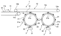
- FIG. 1 It is sectional drawing which shows the transfer mechanism of the apparatus of FIG. It is (a) top view, (b) front view, (c) side view which shows the battery material lamination
- the apparatus has a transport mechanism 1 that transports a workpiece W in a predetermined transport direction (the right direction in FIG. 1), and is aligned below the transport mechanism 1 along the transport direction of the workpiece W.
- a transport mechanism 1 that transports a workpiece W in a predetermined transport direction (the right direction in FIG. 1), and is aligned below the transport mechanism 1 along the transport direction of the workpiece W.
- the transport mechanism 1, the transfer mechanism 2, and the stacking mechanism 3 are arranged along the vertical direction.
- the transport mechanism 1 includes a first transport mechanism 11 disposed on the upstream side in the transport direction of the work W and a second transport mechanism 12 disposed on the downstream side in the transport direction of the work W.
- the upstream end portion in the transport direction of the transport mechanism 12 and the downstream end portion in the transport direction of the first transport mechanism 11 are arranged so as to overlap each other.
- the first transport mechanism 11 includes a main drive shaft 11a provided on the downstream side in the transport direction of the workpiece W, a driven shaft (not shown) provided on the upstream side in the transport direction of the work W, and the main drive shaft 11a. It consists of a conveyor belt 11b wound in an endless state between the shafts, and the upper conveyor belt 11b moves in the transport direction when the main drive shaft 11a rotates.
- the second transport mechanism 12 includes a main drive shaft 12a provided on the downstream side in the transport direction of the work W, a driven shaft 12b provided on the upstream side in the transport direction of the work W, and the main drive shaft 12a and the driven shaft 12b.
- the conveyor belt 12c is wound in an endless state between the two, and the main belt 12a rotates to move the lower belt conveyor 12c in the transport direction.
- the workpiece W moves downstream in the conveying direction according to the movement of the upper belt conveyor 11b. It is sequentially conveyed toward. Then, when the work W reaches the downstream end of the first transport mechanism 11, the work W is held by suction on the lower conveyor belt 12c of the second transport mechanism 12 by suction, As the belt conveyor 12c on the lower side moves, the paper is sequentially transported in a suspended state toward the downstream side in the transport direction.
- the workpiece W is stacked by a predetermined number of sheets by the set of transfer mechanism 2 and stacking mechanism 3 on the upstream side in the transport direction, and then the set of downstream side.
- a predetermined number of sheets are stacked by the transfer mechanism 2 and the stacking mechanism 3.
- the transfer mechanism 2 is provided on a linear motor stator 21 having a circular loop traveling track, a plurality of linear motor movable elements 22 provided on the stator 21, and each movable element 22.
- the holding member 23 holding the workpiece W is provided, and the workpiece W is transferred from the upper side to the lower vertical direction.
- the stator 21 is formed in a circular shape when viewed from the front, such as metal, and is provided with a guide rail 21a at the periphery.
- the guide rail 21a has a circular traveling track according to the shape of the stator 21, and a plurality of electromagnets 21b (coil units) are arranged along the entire circumference in the periphery.
- the electromagnet 21 b is controlled by the control unit 100, and the polarity is changed by changing a current supplied from a power supply (not shown).
- the mover 22 is formed in a metal U-shaped cross section, and is provided in a state where it can travel along the guide rail 21 a of the stator 21.
- the movable element 22 is provided with a permanent magnet inside, and the permanent magnet receives an attractive force or a repulsive force due to a change in polarity of the electromagnet 21 b of the stator 21.
- the control unit 100 repeats the change in the polarity of each electromagnet 21b of the stator 21 along a predetermined direction
- the permanent magnet of the mover 22 is sequentially changed to the polarity of the electromagnet 21b of the stator 21 accordingly.
- the movable element 22 Since the movable element 22 receives a propulsive force in a predetermined direction by being pulled, the movable element 22 travels while drawing a circular path along the traveling path of the stator 21. At this time, the travel speed of the mover 22 can be changed or the mover 22 can be stopped by changing the time interval of the polarity change of each electromagnet 21 b of the stator 21 by the control unit 100.
- the holding member 23 is provided on the outer side in the radial direction of the movable element 22, and the tip portion is formed as a flat holding surface 23 a that holds the workpiece W by, for example, suction. According to the traveling, the stator 21 rotates on a circular traveling track.
- the other surface is held by the holding member 23 of the transfer mechanism 2, and the one surface and the other surface are rotated according to the rotation of the holding member 32. Then, the sheet is rotated and conveyed to the lower layering mechanism 3 while reversing the front and back, and then laminated on a layering table 31 (to be described later) of the layering mechanism 3 while facing one side.
- the laminating mechanism 3 includes a laminating table 31 for sequentially laminating the workpieces W rotated and transferred by the holding member 23, and gradually moves downward each time the workpieces W are laminated by the control unit 100 via the driving device. Or the position and orientation of the workpiece W can be adjusted by moving and rotating in the plane direction. Note that when adjusting the position and orientation of the workpiece W, the workpiece W may be imaged by an imaging device (not shown).
- the stacking table 31 is provided with a claw member 32 at a front position in the rotational conveyance direction of the workpiece W.
- the claw member 32 is configured to receive a front side edge portion of the workpiece W when the workpiece W is stacked by the holding member 23.
- work W may be provided.
- control unit 100 performs a transport operation of the transport mechanism 1, a travel operation of the movable element 22 in the stator 21 of the transfer mechanism 2, an operation of the stacking table 31 (drive device) of the stacking mechanism 3, and the like. To control.
- the workpiece W is moved downstream in the conveyance direction according to the movement of the upper belt conveyor 11b. It is conveyed sequentially. Then, when the work W reaches the downstream end of the first transport mechanism 11, the work W is held by suction on the lower conveyor belt 12c of the second transport mechanism 12 by suction, As the belt conveyor 12c on the lower side moves, the paper is sequentially transported in a suspended state toward the downstream side in the transport direction.
- the workpiece W has one surface formed by rotating the holding member 23 half a clockwise direction as the mover 22 travels along the travel path of the stator 21.
- the other side is rotated and conveyed sequentially to the lower stacking table 31 while reversing the front and back.
- the workpiece W is released from the holding state by the holding member 23, so that the front side edge portion is received by the claw member 32 and the one surface is directed to the laminated table 31.
- they are sequentially stacked.
- work W is laminated
- maintenance member 23 will further rotate clockwise by a half circumference, and it will be 2nd again. Return to the place where the workpiece W is held in the transport mechanism 12.
- the stacking table 31 moves along with the stack of workpieces W or is transferred to another location by gripping the stack of workpieces W.
- the stacking of the predetermined number of workpieces W related to the predetermined set on the upstream side or the downstream side is completed, the stacking of the workpieces W related to another set on the downstream side or the upstream side is started without interruption.
- a predetermined number of workpieces W related to a predetermined set on the upstream side or the downstream side can be conveyed to the next step. For this reason, as compared with the conventional intermittent laminating apparatus, the work W can be laminated and transported continuously, and the battery manufacturing efficiency can be dramatically improved.
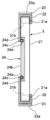
- the guide mechanism 24 includes a cam member 24b having a cam groove 24a having a predetermined track, a support member 24d connected to the holding member 23, and a support member 24d.
- the guide mechanism 24 slides on the cam groove 24a.
- a cam follower 24c that can be fitted.
- the cam groove 24a is formed in a substantially annular track that protrudes in the radial direction at the upper end portion and the lower end portion.
- the holding member 23 is guided to the cam groove 24a via the cam follower 24c of the guide mechanism 24 when rotating in accordance with the rotation of the movable element 22 in the stator 21, so that the vicinity of the top dead center of rotation is reached. Therefore, the workpiece W conveyed from the second conveyance mechanism 12 can be reliably held. Further, the workpiece W can be reliably stacked on the stacking table 31 of the stacking mechanism 3 because it approaches the stacking table 31 of the stacking mechanism 3 near the bottom dead center of the rotation.
- the holding member 23 has a holding surface 23a for holding the workpiece W immediately before holding the workpiece W transferred from the second transfer mechanism 12 by the guide mechanism 24 or the like. May be close to the second transport mechanism 12 in a state parallel to the transport plane of the workpiece W.
- the holding surface 23 a holding the workpiece W has the second transfer mechanism 12. May be separated from the second transport mechanism 12 in a state parallel to the transport plane of the workpiece W.
- the holding member 23 is stacked by the stacking mechanism 3 in a state where the work W is inclined by the guide mechanism 24 or the like so that the front edge in the rotational conveyance direction of the work W is positioned below the rear edge. It may be laminated on the table 31.
- the guide mechanism 24 is composed of the cam groove 24a, the cam member 24b, the cam follower 24c, and the support member 24d, but may be other mechanisms such as a cylinder mechanism, a linear mechanism, and a plunger mechanism.
- the workpiece W conveyed from the conveyance mechanism 1 is held at two different locations on the conveyance mechanism 1 and the workpiece W rotated and conveyed is stacked at two different locations on the stacking mechanism 3. ing.
- this apparatus includes a linear motor stator 21 having an oval running track, a plurality of movers 22 provided on the stator 21, and each mover 22. Holding member 23 to hold.
- the holding member 23 includes a first holding member 23A and a second holding member 23B, and the first holding member 23A and the second holding member 23B are alternately arranged along the circumferential direction of the stator 21. Yes.
- first holding member 23A and the second holding member 23B on the transport mechanism 1 side, and the first holding member 23A and the second holding member 23B on the stacking mechanism 3 side are illustrated. Although shown, in actuality, more first holding members 23A and second holding members 23B are alternately arranged.
- the first holding member 23A is brought close to the transport mechanism 1 or the stacking mechanism 3 by the first guide mechanism 24A having the same mechanism as that of the second embodiment. Further, the second holding member 23B comes close to the transport mechanism 1 or the stacking mechanism 3 by the second cam mechanism 24B having the same mechanism as that of the second embodiment.
- the first guide mechanism 24A is configured such that the cam follower 24c of the holding member 23 is fitted in the cam groove 24a formed on the front side of the stator 21, while the second guide mechanism 24B The cam follower 24c of the holding member 23 is fitted in the cam groove 24a formed on the back side of the stator 21.
- work W can be hold
- the workpiece W is transferred by the two holding members 23 of the first holding member 23A and the second holding member 23B.
- the workpiece W is transferred by three or more holding members 23. You may transfer.
- the transport mechanism 1, the transfer mechanism 2, and the stacking mechanism 3 are arranged side by side in the horizontal direction so that the workpiece W is transferred while maintaining the horizontal state.
- the transport mechanism 1 is composed of a belt conveyor that rotates in an endless state, and transports the workpiece W while placing it in a horizontal state.
- the stator 21 is disposed in a horizontally lying state in the horizontal direction of the workpiece, and the movable element 22 rotates in the horizontal direction of the workpiece along the traveling path of the stator 21.
- the holding member 23 is formed in a shape extending in the axial direction of the rotation of the mover 22, and rotates and conveys the workpiece W in the horizontal direction as the mover 22 rotates.
- a pair of movers 22 and holding members 23 are shown on the transport mechanism 1 side and the laminating mechanism 3 side, but actually a plurality of sets of movers 22 and holding members 23 are shown.
- the stator 21 is provided.
- the stacking mechanism 3 is composed of a belt conveyor that rotates in an endless state, and after the workpieces W are stacked in a horizontal state, it is conveyed in a predetermined direction.
- the workpiece W is held in a horizontal state at a predetermined position by the holding member 23 of the transfer mechanism 2 in the process of being transferred while being mounted in the horizontal state by the transfer mechanism 1, and according to the rotational travel of the mover 22. After being rotated and transported in a horizontal state, it is stacked in a horizontal state at a predetermined position of the stacking mechanism 3. Thereafter, the stacked body of the workpieces W stacked in a predetermined number is conveyed in a predetermined direction by the belt conveyor of the stacking mechanism 3.
- the holding member 23 may be brought close to the transport mechanism 1 or the stacking mechanism 3 when the work W is held or stacked.
- the workpiece is transferred along the horizontal direction, it may be transferred along other directions as long as it is parallel to the plane direction of the workpiece.
- the stacking mechanism 3 is constituted by a linear motor.
- the stacking mechanism 3 includes a stacking stator 33 for a linear motor having a predetermined traveling path, and a stacking mover for a linear motor provided on the stacking stator 33. 34, a stacking table 31 provided on the stacking movable element 34, on which the workpieces W are stacked, and the control unit 100 control the travel of the movable element 22 in the stator 21.
- the stacking table 31 can be quickly arranged at a predetermined stacking location, and after the stacking of the workpieces W, the stacking table 31 is quickly transferred to another location for each workpiece W. Therefore, it is possible to efficiently produce a laminate of a plurality of sets of workpieces W.
- the stacking table 31 of the stacking mechanism 3 moves by a predetermined distance forward in the rotational transport direction while synchronizing with the rotational transport of the workpiece W. After being stacked, it may be moved by a predetermined distance in the rotational conveyance direction and returned to the original position. According to this, the speed difference between the workpiece W and the stacking table 31 at the time of stacking is absorbed by moving the stacking table 31 by a predetermined distance forward in the rotational transport direction while synchronizing with the rotating transport of the workpiece W.
- the lamination mechanism 3 is configured by a linear motor, but may be configured by other mechanisms such as a ball screw.
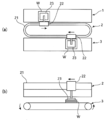
- the holding member 23 may hold the workpiece W by suction with a predetermined gap t between the workpiece W and the workpiece W. According to this, when the holding member 23 holds the workpiece W, it is possible to prevent the holding surface 23a of the holding member 23 from rubbing against the surface of the workpiece W. Further, when a plurality of transfer mechanisms 2 are provided, when the workpiece W is passed through a predetermined transfer mechanism 2 in order to hold the workpiece W by the holding member 23 of the next transfer mechanism 2, the predetermined transfer mechanism 2. The holding member 23 can prevent the workpiece W from being inadvertently held.
- the holding member 23 has a holding surface 23a for holding the workpiece W formed on a flat surface.
- the holding surface 23a for holding the workpiece W is loosely shaped like a mountain. You may use what was formed in the curved surface. According to this, since the work W held by the holding member 23 is stretched, it is possible to prevent the work W from fluttering or dripping during the rotational conveyance of the work W by the holding member 23.
- the shape and size of the holding member 23 are not particularly limited, but are formed in a shape and size that do not interfere with the claw member 32 and other members when the workpiece W is stacked on the stacking table 31. Is preferred.
- the present invention is not necessarily applied to the battery material laminating apparatus. That is, the holding member 23 holds the workpiece W at a predetermined location, and after the mover 22 rotates and conveys the workpiece W as it travels along the traveling path of the stator 21, the workpiece W is moved to another location. As long as it has the transfer mechanism 2 (battery material transfer apparatus) mounted in the place, you may apply to the other apparatus related to battery manufacture.
- the transfer mechanism 2 battery material transfer apparatus
Landscapes
- Engineering & Computer Science (AREA)
- Manufacturing & Machinery (AREA)
- Chemical & Material Sciences (AREA)
- Chemical Kinetics & Catalysis (AREA)
- Electrochemistry (AREA)
- General Chemical & Material Sciences (AREA)
- Mechanical Engineering (AREA)
- Secondary Cells (AREA)
- Stacking Of Articles And Auxiliary Devices (AREA)
- Specific Conveyance Elements (AREA)
Priority Applications (2)
| Application Number | Priority Date | Filing Date | Title |
|---|---|---|---|
| US17/056,494 US11575144B2 (en) | 2018-06-12 | 2019-05-27 | Battery material stacking system |
| CN201980037441.XA CN112219304B (zh) | 2018-06-12 | 2019-05-27 | 电池材料层叠装置 |
Applications Claiming Priority (2)
| Application Number | Priority Date | Filing Date | Title |
|---|---|---|---|
| JP2018-111540 | 2018-06-12 | ||
| JP2018111540A JP6819652B2 (ja) | 2018-06-12 | 2018-06-12 | 電池材料積層装置 |
Publications (1)
| Publication Number | Publication Date |
|---|---|
| WO2019239863A1 true WO2019239863A1 (ja) | 2019-12-19 |
Family
ID=68843012
Family Applications (1)
| Application Number | Title | Priority Date | Filing Date |
|---|---|---|---|
| PCT/JP2019/020802 Ceased WO2019239863A1 (ja) | 2018-06-12 | 2019-05-27 | 電池材料積層装置 |
Country Status (5)
| Country | Link |
|---|---|
| US (1) | US11575144B2 (https=) |
| JP (1) | JP6819652B2 (https=) |
| CN (1) | CN112219304B (https=) |
| TW (1) | TWI720505B (https=) |
| WO (1) | WO2019239863A1 (https=) |
Cited By (4)
| Publication number | Priority date | Publication date | Assignee | Title |
|---|---|---|---|---|
| CN113879836A (zh) * | 2020-07-01 | 2022-01-04 | 法麦凯尼柯数据股份公司 | 用于转移制品的设备和方法 |
| EP4223680A4 (en) * | 2020-09-30 | 2024-03-27 | Panasonic Intellectual Property Management Co., Ltd. | LAMINATION DEVICE |
| US20240150148A1 (en) * | 2022-06-15 | 2024-05-09 | Murata Manufacturing Co., Ltd. | Stacking apparatus and stacking system |
| US12172420B2 (en) * | 2020-04-30 | 2024-12-24 | Murata Manufacturing Co., Ltd. | Lamination device |
Families Citing this family (21)
| Publication number | Priority date | Publication date | Assignee | Title |
|---|---|---|---|---|
| JP6888654B2 (ja) | 2019-08-23 | 2021-06-16 | トヨタ自動車株式会社 | 積層体保持装置 |
| CN115461287B (zh) * | 2020-04-30 | 2025-11-11 | 株式会社村田制作所 | 层叠装置 |
| JP7503462B2 (ja) * | 2020-09-16 | 2024-06-20 | パナソニックホールディングス株式会社 | シート材搬送装置 |
| US12312186B2 (en) * | 2020-09-30 | 2025-05-27 | Panasonic Holdings Corporation | Workpiece conveyance device |
| CN112768744B (zh) * | 2021-01-21 | 2022-10-04 | 深圳市科瑞新能源装备技术有限公司 | 电池制造设备 |
| JP7267480B2 (ja) * | 2021-04-28 | 2023-05-01 | プライムプラネットエナジー&ソリューションズ株式会社 | 電極体製造装置 |
| US12374712B2 (en) | 2021-04-28 | 2025-07-29 | Prime Planet Energy & Solutions, Inc. | Electrode body producing apparatus |
| EP4270569A1 (en) * | 2021-10-14 | 2023-11-01 | ATS Automation Tooling Systems Inc. | Automated battery assembly systems and related methods |
| CN113809406B (zh) * | 2021-10-20 | 2024-06-11 | 广州阿普顿自动化系统有限公司 | 动力电池包柔性生产系统 |
| DE102022105399A1 (de) | 2022-03-08 | 2023-09-14 | Körber Technologies Gmbh | Zellstapelanlage zum Stapeln von Segmenten von Energiezellen, Verfahren zur Steuerung einer derartigen Zellstapelanlage, Teilvorrichtung einer oder in einer Zellstapelanlage und Teilverfahren beim Herstellen von Zellstapeln in einer Zellstapelanlage |
| DE102022105402A1 (de) * | 2022-03-08 | 2023-09-14 | Körber Technologies Gmbh | Zellstapelanlage und Verfahren zum Stapeln |
| DE102022105394A1 (de) * | 2022-03-08 | 2023-09-14 | Körber Technologies Gmbh | Vorrichtung und Verfahren zum Bilden und Befördern von durch Segmente gebildeten Zellstapeln für die Energiezellen produzierende Industrie |
| DE102022105396A1 (de) | 2022-03-08 | 2023-09-14 | Körber Technologies Gmbh | Zellstapelanlage zum Stapeln von Segmenten von Energiezellen, Verfahren zur Steuerung einer derartigen Zellstapelanlage, Teilvorrichtung einer oder in einer Zellstapelanlage und Teilverfahren beim Herstellen von Zellstapeln in einer Zellstapelanlage |
| DE102022105397A1 (de) | 2022-03-08 | 2023-09-14 | Körber Technologies Gmbh | Zellstapelanlage zum Stapeln von Segmenten von Energiezellen, Verfahren zur Steuerung einer derartigen Zellstapelanlage, Teilvorrichtung einer oder in einer Zellstapelanlage und Teilverfahren beim Herstellen von Zellstapeln in einer Zellstapelanlage |
| DE102022115207A1 (de) | 2022-06-17 | 2023-12-28 | Mb Atech Gmbh | Vorrichtung zur Herstellung von Modulen oder Vorstufen von Modulen |
| DE102022124788B3 (de) * | 2022-09-27 | 2024-01-18 | Mb Atech Gmbh | Inspektion bei der Herstellung von Modulen oder Vorstufen von Modulen |
| DE102023100483A1 (de) * | 2023-01-11 | 2024-07-11 | Körber Technologies Gmbh | Vorrichtung und Verfahren für die Energiezellen produzierende Industrie |
| CN120826364A (zh) * | 2023-05-24 | 2025-10-21 | 株式会社Lg新能源 | 物体装载设备 |
| KR20240177190A (ko) * | 2023-06-19 | 2024-12-27 | 주식회사 엘지에너지솔루션 | 대상물 적재설비 |
| IT202300027657A1 (it) * | 2023-12-21 | 2025-06-21 | Fameccanica Data Spa | Apparato e procedimento di movimentazione di monocelle per la produzione di dispositivi di accumulo di energia elettrica |
| EP4678575A1 (de) | 2024-07-10 | 2026-01-14 | Grob-Werke GmbH & Co. KG | Vorrichtung, transporteinheit und verfahren zum transportieren von biegeschlaffen elementen |
Citations (2)
| Publication number | Priority date | Publication date | Assignee | Title |
|---|---|---|---|---|
| JP2012221707A (ja) * | 2011-04-07 | 2012-11-12 | Kyoto Seisakusho Co Ltd | セパレータ搬送装置およびセパレータ搬送方法 |
| JP2017004615A (ja) * | 2015-06-04 | 2017-01-05 | 株式会社豊田自動織機 | 電極積層方法および電極積層装置 |
Family Cites Families (12)
| Publication number | Priority date | Publication date | Assignee | Title |
|---|---|---|---|---|
| US3477558A (en) * | 1966-10-27 | 1969-11-11 | Fred J Fleischauer | Air lift and vacuum conveyors and foraminous belt means therefor |
| US3822008A (en) * | 1973-02-01 | 1974-07-02 | Jones & Co Inc R A | Transfer apparatus for packaging machine |
| JP4608238B2 (ja) * | 2004-05-21 | 2011-01-12 | 日本トムソン株式会社 | アライメントステージ装置 |
| JP2006333652A (ja) * | 2005-05-27 | 2006-12-07 | Nikki Denso Kk | リニアモータ及び精密回転テーブル |
| JP2010033922A (ja) * | 2008-07-30 | 2010-02-12 | Nec Tokin Corp | 積層型二次電池 |
| JP5701639B2 (ja) | 2011-02-18 | 2015-04-15 | 株式会社京都製作所 | 極板積載装置 |
| JP5602659B2 (ja) * | 2011-02-18 | 2014-10-08 | 株式会社京都製作所 | 極板積載装置 |
| JP5706743B2 (ja) * | 2011-04-07 | 2015-04-22 | 株式会社京都製作所 | 積層装置および積層方法 |
| JP5901135B2 (ja) * | 2011-04-07 | 2016-04-06 | 株式会社京都製作所 | 積層装置および積層方法 |
| CN105210228B (zh) * | 2013-05-21 | 2017-05-10 | 日机装株式会社 | 层叠装置以及层叠方法 |
| JP6657785B2 (ja) | 2015-10-28 | 2020-03-04 | 株式会社豊田自動織機 | 積層装置および電極積層方法 |
| JP6444926B2 (ja) * | 2016-04-11 | 2018-12-26 | Ckd株式会社 | 積層装置 |
-
2018
- 2018-06-12 JP JP2018111540A patent/JP6819652B2/ja active Active
-
2019
- 2019-05-27 WO PCT/JP2019/020802 patent/WO2019239863A1/ja not_active Ceased
- 2019-05-27 CN CN201980037441.XA patent/CN112219304B/zh active Active
- 2019-05-27 US US17/056,494 patent/US11575144B2/en active Active
- 2019-06-10 TW TW108120000A patent/TWI720505B/zh active
Patent Citations (2)
| Publication number | Priority date | Publication date | Assignee | Title |
|---|---|---|---|---|
| JP2012221707A (ja) * | 2011-04-07 | 2012-11-12 | Kyoto Seisakusho Co Ltd | セパレータ搬送装置およびセパレータ搬送方法 |
| JP2017004615A (ja) * | 2015-06-04 | 2017-01-05 | 株式会社豊田自動織機 | 電極積層方法および電極積層装置 |
Cited By (5)
| Publication number | Priority date | Publication date | Assignee | Title |
|---|---|---|---|---|
| US12172420B2 (en) * | 2020-04-30 | 2024-12-24 | Murata Manufacturing Co., Ltd. | Lamination device |
| CN113879836A (zh) * | 2020-07-01 | 2022-01-04 | 法麦凯尼柯数据股份公司 | 用于转移制品的设备和方法 |
| CN113879836B (zh) * | 2020-07-01 | 2023-10-20 | 法麦凯尼柯数据股份公司 | 用于转移制品的设备和方法 |
| EP4223680A4 (en) * | 2020-09-30 | 2024-03-27 | Panasonic Intellectual Property Management Co., Ltd. | LAMINATION DEVICE |
| US20240150148A1 (en) * | 2022-06-15 | 2024-05-09 | Murata Manufacturing Co., Ltd. | Stacking apparatus and stacking system |
Also Published As
| Publication number | Publication date |
|---|---|
| US20210202976A1 (en) | 2021-07-01 |
| CN112219304A (zh) | 2021-01-12 |
| US11575144B2 (en) | 2023-02-07 |
| TW202000567A (zh) | 2020-01-01 |
| JP6819652B2 (ja) | 2021-01-27 |
| TWI720505B (zh) | 2021-03-01 |
| JP2019215977A (ja) | 2019-12-19 |
| CN112219304B (zh) | 2024-05-17 |
Similar Documents
| Publication | Publication Date | Title |
|---|---|---|
| WO2019239863A1 (ja) | 電池材料積層装置 | |
| JP2019200926A (ja) | 電池材料積層装置 | |
| JP2014165055A (ja) | 積層型電池製造方法及びその装置 | |
| KR20190089761A (ko) | 적층장치 및 적층방법 | |
| TW201300303A (zh) | 用於傳送基板的裝置 | |
| US11458847B2 (en) | Article transferring device | |
| JP2022049042A (ja) | シート材搬送装置 | |
| JP6334353B2 (ja) | ワークの積載方法 | |
| CN115836420B (zh) | 层叠装置 | |
| JP7667790B2 (ja) | ワーク搬送装置 | |
| CN110190337A (zh) | 一种切叠一体机 | |
| JP2020064812A (ja) | 電池材料積層装置 | |
| JP2016197527A (ja) | ワーク積層装置 | |
| KR20140015781A (ko) | 극판 타발 장치 | |
| KR20130009904A (ko) | 기판 이송 장치 | |
| JP7077666B2 (ja) | 搬送装置、および搬送システム | |
| CN116728083A (zh) | 一种磁力泵磁转子组装机 | |
| CN221486566U (zh) | 叠片系统 | |
| JP7696988B1 (ja) | 搬送装置 | |
| CN109795906A (zh) | 薄膜材料匀速移送装置 | |
| CN120736273A (zh) | 一种极片输送装置工作方法 | |
| TWI429575B (zh) | 一種送線滾輪機構 | |
| JP2020063141A (ja) | ワーク積層装置 |
Legal Events
| Date | Code | Title | Description |
|---|---|---|---|
| 121 | Ep: the epo has been informed by wipo that ep was designated in this application |
Ref document number: 19819631 Country of ref document: EP Kind code of ref document: A1 |
|
| NENP | Non-entry into the national phase |
Ref country code: DE |
|
| 122 | Ep: pct application non-entry in european phase |
Ref document number: 19819631 Country of ref document: EP Kind code of ref document: A1 |