WO2019239685A1 - 電気接続箱 - Google Patents
電気接続箱 Download PDFInfo
- Publication number
- WO2019239685A1 WO2019239685A1 PCT/JP2019/014696 JP2019014696W WO2019239685A1 WO 2019239685 A1 WO2019239685 A1 WO 2019239685A1 JP 2019014696 W JP2019014696 W JP 2019014696W WO 2019239685 A1 WO2019239685 A1 WO 2019239685A1
- Authority
- WO
- WIPO (PCT)
- Prior art keywords
- wall portion
- peripheral wall
- box body
- cover member
- lock
- Prior art date
- Legal status (The legal status is an assumption and is not a legal conclusion. Google has not performed a legal analysis and makes no representation as to the accuracy of the status listed.)
- Ceased
Links
Images


Classifications
-
- H—ELECTRICITY
- H05—ELECTRIC TECHNIQUES NOT OTHERWISE PROVIDED FOR
- H05K—PRINTED CIRCUITS; CASINGS OR CONSTRUCTIONAL DETAILS OF ELECTRIC APPARATUS; MANUFACTURE OF ASSEMBLAGES OF ELECTRICAL COMPONENTS
- H05K7/00—Constructional details common to different types of electric apparatus
- H05K7/20—Modifications to facilitate cooling, ventilating, or heating
- H05K7/20845—Modifications to facilitate cooling, ventilating, or heating for automotive electronic casings
- H05K7/20854—Heat transfer by conduction from internal heat source to heat radiating structure
-
- B—PERFORMING OPERATIONS; TRANSPORTING
- B60—VEHICLES IN GENERAL
- B60R—VEHICLES, VEHICLE FITTINGS, OR VEHICLE PARTS, NOT OTHERWISE PROVIDED FOR
- B60R16/00—Electric or fluid circuits specially adapted for vehicles and not otherwise provided for; Arrangement of elements of electric or fluid circuits specially adapted for vehicles and not otherwise provided for
- B60R16/02—Electric or fluid circuits specially adapted for vehicles and not otherwise provided for; Arrangement of elements of electric or fluid circuits specially adapted for vehicles and not otherwise provided for electric constitutive elements
- B60R16/023—Electric or fluid circuits specially adapted for vehicles and not otherwise provided for; Arrangement of elements of electric or fluid circuits specially adapted for vehicles and not otherwise provided for electric constitutive elements for transmission of signals between vehicle parts or subsystems
- B60R16/0238—Electrical distribution centers
-
- H—ELECTRICITY
- H02—GENERATION; CONVERSION OR DISTRIBUTION OF ELECTRIC POWER
- H02G—INSTALLATION OF ELECTRIC CABLES OR LINES, OR OF COMBINED OPTICAL AND ELECTRIC CABLES OR LINES
- H02G3/00—Installations of electric cables or lines or protective tubing therefor in or on buildings, equivalent structures or vehicles
- H02G3/02—Details
- H02G3/08—Distribution boxes; Connection or junction boxes
- H02G3/088—Dustproof, splashproof, drip-proof, waterproof, or flameproof casings or inlets
-
- H—ELECTRICITY
- H02—GENERATION; CONVERSION OR DISTRIBUTION OF ELECTRIC POWER
- H02G—INSTALLATION OF ELECTRIC CABLES OR LINES, OR OF COMBINED OPTICAL AND ELECTRIC CABLES OR LINES
- H02G3/00—Installations of electric cables or lines or protective tubing therefor in or on buildings, equivalent structures or vehicles
- H02G3/02—Details
- H02G3/08—Distribution boxes; Connection or junction boxes
- H02G3/14—Fastening of cover or lid to box
-
- H—ELECTRICITY
- H02—GENERATION; CONVERSION OR DISTRIBUTION OF ELECTRIC POWER
- H02G—INSTALLATION OF ELECTRIC CABLES OR LINES, OR OF COMBINED OPTICAL AND ELECTRIC CABLES OR LINES
- H02G3/00—Installations of electric cables or lines or protective tubing therefor in or on buildings, equivalent structures or vehicles
- H02G3/02—Details
- H02G3/08—Distribution boxes; Connection or junction boxes
- H02G3/16—Distribution boxes; Connection or junction boxes structurally associated with support for line-connecting terminals within the box
-
- H—ELECTRICITY
- H05—ELECTRIC TECHNIQUES NOT OTHERWISE PROVIDED FOR
- H05K—PRINTED CIRCUITS; CASINGS OR CONSTRUCTIONAL DETAILS OF ELECTRIC APPARATUS; MANUFACTURE OF ASSEMBLAGES OF ELECTRICAL COMPONENTS
- H05K5/00—Casings, cabinets or drawers for electric apparatus
- H05K5/0026—Casings, cabinets or drawers for electric apparatus provided with connectors and printed circuit boards [PCB], e.g. automotive electronic control units
- H05K5/0047—Casings, cabinets or drawers for electric apparatus provided with connectors and printed circuit boards [PCB], e.g. automotive electronic control units having a two-part housing enclosing a PCB
- H05K5/0052—Casings, cabinets or drawers for electric apparatus provided with connectors and printed circuit boards [PCB], e.g. automotive electronic control units having a two-part housing enclosing a PCB characterized by joining features of the housing parts
-
- H—ELECTRICITY
- H05—ELECTRIC TECHNIQUES NOT OTHERWISE PROVIDED FOR
- H05K—PRINTED CIRCUITS; CASINGS OR CONSTRUCTIONAL DETAILS OF ELECTRIC APPARATUS; MANUFACTURE OF ASSEMBLAGES OF ELECTRICAL COMPONENTS
- H05K5/00—Casings, cabinets or drawers for electric apparatus
- H05K5/06—Hermetically-sealed casings
- H05K5/063—Hermetically-sealed casings sealed by a labyrinth structure provided at the joining parts
-
- H—ELECTRICITY
- H05—ELECTRIC TECHNIQUES NOT OTHERWISE PROVIDED FOR
- H05K—PRINTED CIRCUITS; CASINGS OR CONSTRUCTIONAL DETAILS OF ELECTRIC APPARATUS; MANUFACTURE OF ASSEMBLAGES OF ELECTRICAL COMPONENTS
- H05K7/00—Constructional details common to different types of electric apparatus
- H05K7/20—Modifications to facilitate cooling, ventilating, or heating
- H05K7/2039—Modifications to facilitate cooling, ventilating, or heating characterised by the heat transfer by conduction from the heat generating element to a dissipating body
Definitions
- the present disclosure relates to an electrical junction box mounted on an automobile or the like, and particularly to an electrical junction box provided with a lock mechanism that detachably attaches a cover member to the box body.
- electrical connection boxes such as relay boxes, fuse boxes, and junction boxes have been used in the electrical system of automobiles, and a large number of electrical components such as relays and fuses are concentrated in such electrical connection boxes. As a result, the efficiency of electrical wiring and the maintenance such as replacement are improved.
- Patent Document 1 Japanese Patent Application Laid-Open No. 11-307654
- Patent Document 2 Japanese Patent Application Laid-Open No. 2012-235654
- the lock mechanism includes an elastic lock portion protruding in a cantilever manner on the cover member and a locked portion provided on the box body.
- the elastic lock portion engages with the locked portion and is elastically deformed to allow insertion of the elastic lock portion into the locked portion, and the elastic lock portion is locked.
- the elastic lock part engages with the locked part and is held in the assembled state between the cover member and the box body.
- an object of the present invention is to provide an electrical junction box having a novel structure that can improve the heat dissipation of the electrical junction box while maintaining the durability of the lock mechanism.
- An electrical connection box of the present disclosure includes a box body provided with a plurality of component mounting portions on one surface to which electrical components are mounted, a cover member that covers the one surface of the box body, and the box body A locked portion provided on the peripheral wall portion and a lock mechanism including an elastic lock portion provided in a cantilever manner on the cover member, and the top wall portion of the cover member is provided on the peripheral wall portion of the cover member
- the elastic lock portion is formed of a resin material having a higher thermal conductivity than the elastic lock portion, and the elastic lock portion provided on the peripheral wall portion of the cover member is more elastic than the top wall portion of the cover member.
- This is an electrical junction box made of a large resin material.
- the present disclosure it is possible to reduce or prevent heat from being accumulated in the electrical junction box by promoting heat radiation from the cover member to the outside. Further, it is possible to reduce or eliminate the possibility that the elastic lock portion breaks when the cover member is detachably mounted and fixed to the box body via the lock mechanism, and the heat dissipation of the electric connection box can be improved. it can.
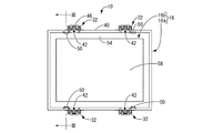
- FIG. 1 is an overall perspective view showing the electrical junction box according to the first embodiment.
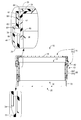
- FIG. 2 is a plan view of the electrical junction box shown in FIG. 3 is an enlarged sectional view taken along the line III-III in FIG. 4 is a plan view of the box body shown in FIG.
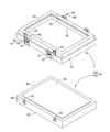
- FIG. 5 is an exploded perspective view of the cover member shown in FIG.
- the electrical junction box of the present disclosure is: (1) A plurality of component mounting portions on which electrical components are mounted are provided on one surface, a cover member that covers the one surface of the box body, and a peripheral wall portion of the box body.
- the elastic lock provided with a locked portion and a lock mechanism including an elastic lock portion provided in a cantilever manner on the cover member, wherein the top wall portion of the cover member is provided on the peripheral wall portion of the cover member.
- the elastic lock portion provided on the peripheral wall portion of the cover member is formed of a resin material having a higher elasticity than that of the top wall portion of the cover member. It is an electrical junction box.
- the top wall portion of the cover member is formed of a resin material having a higher thermal conductivity than the elastic lock portion provided on the peripheral wall portion of the cover member.
- the elastic lock portion is formed of a resin material that is more elastic than the top wall portion.
- the cover member may be formed by using two-color molding, and the top wall portion and the elastic lock portion may be formed of different resin materials, or may be assembled with each other after being separately molded with different resin materials.
- the cover member is formed separately from the frame peripheral wall portion integrally provided with the elastic lock portion and the frame peripheral wall portion, and is detachably assembled and fixed to the frame peripheral wall portion. It is preferable that the entire peripheral wall portion of the frame body is made of a resin material having a larger elasticity than that of the top wall portion.
- the cover member includes a frame peripheral wall portion integrally provided with an elastic lock portion, and a ceiling wall portion that is formed separately from the frame peripheral wall portion and is detachably assembled and fixed to the frame peripheral wall portion. Yes. Thereby, it becomes easy to form a frame surrounding wall part and a ceiling wall part with a separate material which can exhibit each required characteristic, and can aim at the improvement of manufacturing efficiency compared with 2 color molding etc.
- the top wall is detachably assembled and fixed to the frame peripheral wall. Therefore, it is possible to easily realize a configuration capable of improving the heat dissipation of the electrical junction box while maintaining the durability of the lock mechanism. Furthermore, even when any one of the frame body peripheral wall portion and the ceiling wall portion has a problem, it is only necessary to replace either one. As a result, maintenance can be improved.
- the ceiling wall portion is inserted and fixed to the frame body peripheral wall portion from a lower opening facing the box body side in the frame body peripheral wall portion, and the frame body peripheral wall portion is fixed.
- An inner flange protrudes from the upper opening spaced apart from the box body in FIG. 3, and the insertion edge of the ceiling wall portion is formed by overlapping the outer peripheral edge portion of the ceiling wall portion with the inner flange.
- the frame peripheral wall portion is provided with a lock piece that can be bent and deformed outward in the plate thickness direction, and comes into contact with the lock protrusion protruding from the peripheral wall of the top wall portion.
- a water-preventing wall that is held on the lower side of the peripheral wall of the top wall and is located on the outer peripheral side of the contact surface with the box body and protrudes downward. It is preferable that is projected.
- the top wall portion is inserted and assembled from below the frame peripheral wall portion, and the top wall portion comes into contact with the inner flange projecting from the upper opening of the frame peripheral wall portion. Thereby, the insertion end is prescribed
- the lock piece which comprises a lock mechanism is provided in the frame surrounding wall part, and the lock
- a water entry prevention wall is provided at the lower opening of the peripheral wall of the top wall so as to be located on the outer peripheral side of the contact surface with the box body and project downward.
- the peripheral wall portion of the box body has an inner peripheral wall portion that abuts and holds the contact surface of the top wall portion with the box body, and a contact surface of the frame peripheral wall portion with the box body.
- the top wall portion and the frame peripheral wall portion constituting the cover member are respectively held in contact with the inner peripheral wall portion and the outer peripheral wall portion constituting the peripheral wall portion of the box body.
- a water entry prevention wall provided on the peripheral wall of the top wall portion is inserted into a groove provided between the inner peripheral wall portion and the outer peripheral wall portion of the box body.
- the electrical junction box 10 includes a box body 12, an upper cover 16 that is a cover member that covers an upper surface 14 that is one surface of the box body 12, and a box body 12. And a lower cover 20 that covers the lower surface 18 that is the other surface of the lower surface 18.
- “upper” means the upper side in FIGS. 1, 3 and 5
- “lower” means the lower side in FIGS. 1, 3, and 5
- “front” means the right side in FIGS. 2 and 4 are the left side in FIGS. 2 to 4
- the longitudinal direction is the left and right direction in FIGS. 2 to 4
- the width direction is the up and down direction in FIGS.
- the box body 12 has a long rectangular block shape as a whole.
- the box body 12 is integrally formed by injection molding with an insulating synthetic resin such as polypropylene (PP) or polyamide (PA).
- PP polypropylene
- PA polyamide
- the upper surface 14 of the box body 12 has a plurality of relay mounting portions 22 and fuse mounting portions 24 that form a component mounting portion, and are opened upward.
- a plurality of terminal accommodating holes and bus bar accommodating grooves are formed in the lower surface 18 (see FIG. 3) of the box body 12 so as to open downward. Each bus bar is accommodated in a terminal accommodating hole or a bus bar accommodating groove.
- relays 26 and fuses 28, which are electrical components, are mounted on the relay mounting portions 22 and the fuse mounting portions 24, respectively.
- a tab terminal protruding downward from the relay 26 or the fuse 28 is electrically connected to the above-described crimp terminal or bus bar of the end of the electric wire.
- FIG. 3 for ease of understanding, descriptions of the relay mounting portion 22 and the fuse mounting portion 24 that constitute the component mounting portion, and the relay 26 and the fuse 28 that are electrical components are omitted.
- an engagement frame 32 which is a locked portion that constitutes a substantially U-shaped locking mechanism, protrudes outward (in the vertical direction in FIG. 4). More specifically, the engagement frame 32 has a structure in which both end portions are connected to the peripheral wall portion 30 and protruded (see FIG. 4). As shown in FIG. 1, the engaging frame 32 is configured such that a part thereof protrudes toward the upper cover 16 side, that is, upward in the vertical direction, beyond the upper end portion of the peripheral wall portion 30. Further, an engagement protrusion 34 that protrudes inward is provided at the upper end of the engagement frame 32 (see FIG. 4).
- the peripheral wall portion 30 of the box body 12 includes an inner peripheral wall portion 30a provided on the inner peripheral side and an outer peripheral wall portion 30b provided on the outer peripheral side. It is a heavy wall structure.
- the upper end portion between the inner peripheral wall portion 30a and the outer peripheral wall portion 30b is provided with a concave groove 36 that opens upward and extends along the peripheral wall portion 30 with a substantially rectangular cross-sectional shape.
- the upper cover 16 has a substantially rectangular box shape that opens downward as a whole, as shown in FIGS. More specifically, the upper cover 16 constitutes a peripheral wall portion of the upper cover 16 and has a substantially rectangular frame-shaped frame peripheral wall portion 16a in a plan view that opens in the up-down direction, and a generally open opening downward.
- the ceiling wall portion 16b having a rectangular box shape is included.
- An elastic lock portion 42 is provided which is connected and extends in a cantilevered manner toward an obliquely upward upward direction and constitutes a lock mechanism.
- the elastic lock portion 42 is provided with a lock projection 44 that protrudes outward in a substantially triangular cross-sectional shape at a substantially central portion in the extending direction.
- the elastic lock portion 42 is provided with a lock release portion 46 that protrudes in an approximately U shape in a plan view toward the outside at the extended distal end portion.
- a pair of guide portions 47 and 47 are provided on both sides in the width direction of each elastic lock portion 42 so that the elastic lock portion 42 is positioned with respect to the engagement frame 32.
- in the vicinity of the upper opening 48 that is separated from the box body 12 side in the frame peripheral wall portion 16a there are substantially rectangular flat plate-like lock pieces 50 that are spaced apart in the longitudinal direction and that face in the width direction in total.
- the lock piece 50 is cut out on both sides in the width direction and on the upper side by slits (not shown) and is connected to the frame peripheral wall portion 16a in a cantilevered manner on the lower side so as to face outward in the plate thickness direction (left and right direction in FIG. 3). Therefore, it can be bent and deformed. Furthermore, the lock piece 50 is provided with a lock protrusion 52 that protrudes inward in a substantially triangular cross-section toward the inside at a substantially central portion in the extending direction (see FIG. 3). In addition, a substantially rectangular frame-shaped inner flange 54 that protrudes inward is provided in the upper opening 48 that is separated from the box body 12 in the frame peripheral wall 16a.
- the top wall portion 16b has a generally rectangular box shape that opens downward as a whole, and most of the center of the top surface 56 projects in a substantially rectangular shape in plan view to form a protrusion 58. Yes.
- the lock protrusions 62 projecting outward in a substantially triangular cross-sectional shape at a total of four locations spaced apart in the longitudinal direction of the peripheral wall 60 and facing in the width direction. Is provided.
- a water entry preventing wall 66 (see FIG. 3) is provided in the lower opening 64 of the peripheral wall 60 of the top wall 16b.
- the top wall portion 16b constituting the upper cover 16 is a resin material having a thermal conductivity higher than that of the frame peripheral wall portion 16a constituting the peripheral wall portion of the upper cover 16 provided with the elastic lock portion 42, for example, polyphenylene sulfide ( It is integrally formed by injection molding or the like with an insulating synthetic resin such as PPS) or polybutalene terephthalate (PBT).
- the frame peripheral wall portion 16a provided with the elastic lock portion 42 is integrally formed by injection molding or the like with an insulating synthetic resin such as polypropylene (PP), which is more elastic than the top wall portion 16b.
- PP polypropylene
- the assembling and fixing operation of the upper cover 16 configured as described above is performed by inserting the top wall portion 16b into the frame peripheral wall portion 16a from the lower opening 38 facing the box body 12 side of the frame peripheral wall portion 16a. Is executed by. More specifically, by inserting the top wall portion 16b from below the frame peripheral wall portion 16a, the lock projection 62 projecting from the peripheral wall 60 of the top wall portion 16b is bent and deformed outward in the plate thickness direction. It abuts on the lock projection 52 of the lock piece 50 of the frame peripheral wall portion 16a made possible. When the lock protrusion 62 bends and deforms the lock piece 50 outward, further insertion of the top wall 16b into the frame peripheral wall 16a is permitted (see FIG. 3).
- the lock projection 62 of the top wall portion 16b gets over the lock projection 52 of the lock piece 50 and elastically returns. Thereby, the lock protrusion 52 of the lock piece 50 of the frame surrounding wall part 16a and the lock protrusion 62 of the top wall part 16b are engaged.
- the outer peripheral edge portion including the peripheral wall 60 of the top wall portion 16b is overlapped with the inner flange 54, insertion of the top wall portion 16b beyond this is restricted, and the insertion end of the top wall portion 16b is defined. .
- the top cover 16b is held in a state assembled to the frame peripheral wall 16a, and the upper cover 16 is configured.
- the protrusion 58 projecting on the top surface 56 of the top wall portion 16 b opens the upper opening surrounded by the protruding tip of the inner flange 54 of the frame peripheral wall portion 16 a from below. It is blocking. Thereby, the upper surface of the upper cover 16 is substantially flat. Further, in the assembled upper cover 16, the lock piece 50 of the frame peripheral wall portion 16a can be bent outward to release the engagement of the lock protrusion 52 and the lock protrusion 62 of the top wall portion 16b. It is. Thereby, the top wall part 16b can be assembled
- the inner peripheral wall portion 30 a of the peripheral wall portion 30 of the box body 12 has a contact surface 68 of the top wall portion 16 b with the box main body 12. It comes in contact and hold. Thereby, the outer peripheral wall part 30b contacts and hold
- the water enters the upper wall portion 16b of the upper cover 16.
- the prevention wall 66 is pushed in from above so as to be inserted into the groove 36 provided between the inner peripheral wall portion 30a and the outer peripheral wall portion 30b constituting the peripheral wall portion 30 of the box body 12.
- the elastic portions positioned by the guide portions 47 and 47 projecting from the frame peripheral wall portion 16a of the upper cover 16 into the engagement frame 32 projecting near the upper end portion of the peripheral wall portion 30 of the box body 12.
- the lock part 42 is inserted.
- the engagement protrusion 34 of the engagement frame 32 abuts on the lock protrusion 44 of the elastic lock portion 42 to bend and deform the elastic lock portion 42 inward, so that the upper cover 16 is moved onto the box body 12. Further indentation is allowed.
- the engagement protrusion 34 of the box body 12 gets over the lock protrusion 44 of the elastic lock part 42 and elastically returns. Thereby, the engagement protrusion 34 of the box body 12 and the lock protrusion 44 of the upper cover 16 are engaged. As a result, the upper cover 16 is assembled and held in the box body 12, and the electrical junction box 10 is configured.
- the lock projection 46 of the box body 12 and the lock projection of the upper cover 16 are pressed by pressing the lock release portion 46 of the elastic lock portion 42 of the upper cover 16 inward.
- the engagement of the portion 44 can be released.
- the upper cover 16 can be detachably assembled to the box body 12.
- the lower cover 20 is an integrally molded product formed from a synthetic resin, and has a substantially box shape opening upward as shown in FIGS. Further, at the central portion in the vertical direction of the peripheral wall 72 of the lower cover 20, a large number of the outer peripheral wall portions 30 b of the peripheral wall portion 30 of the box main body 12 are protruded outwardly with a substantially triangular cross-sectional shape spaced apart along the outer periphery.
- the support protrusion 74 is provided.
- the lower cover 20 is locked and fixed to the box body 12 by a lock mechanism (not shown).
- the top wall portion 16b constituting the upper cover 16 is made of a resin material having a higher thermal conductivity than the frame peripheral wall portion 16a provided with the elastic lock portion. Is formed. Thereby, it is possible to reduce or prevent heat from being accumulated in the electrical junction box 10 by promoting heat radiation from the upper cover 16 to the outside.
- the frame peripheral wall portion 16a is formed of a resin material having greater elasticity than the top wall portion 16b. As a result, the elastic lock portion 42 formed on the frame peripheral wall portion 16a is sufficiently deformed and secured. Therefore, it is possible to reduce or eliminate the possibility that the elastic lock portion 42 is broken. From the above, it is possible to improve the heat dissipation of the electrical junction box 10 while maintaining the durability of the lock mechanisms 32 and 42.
- the top wall portion 16b and the frame peripheral wall portion 16a constituting the upper cover 16 are separately formed, for example, compared to a case where they are integrally formed by two-color molding or the like.
- the production efficiency can be improved.
- any one of the frame peripheral wall portion 16a and the top wall portion 16b has a problem, it is only necessary to replace one of them, so that the maintainability can be improved.
- a water entry preventing wall 66 that protrudes downward from the contact surface 68 with the box body 12 and protrudes downward is provided at the lower opening 64 of the peripheral wall 60 of the top wall 16b. . Therefore, even if the top wall portion 16b is flooded and water enters between the top wall portion 16b and the frame peripheral wall portion 16a, the water entry preventing wall 66 prevents water from entering the box body 12. Can be surely prevented. Thereby, the waterproofness in the case where the upper cover 16 is divided into the top wall portion 16b and the frame peripheral wall portion 16a can be secured more advantageously.
- the first embodiment has been described in detail as a specific example of the present disclosure, but the present disclosure is not limited to this specific description. Modifications, improvements, and the like within the scope that can achieve the object of the present disclosure are included in the present disclosure. For example, the following embodiments are also included in the technical scope of the present disclosure.
- the top wall portion 16b and the frame peripheral wall portion 16a constituting the upper cover 16 are formed separately, but different materials are used by using a known technique such as two-color molding. May be formed integrally. By forming them integrally, it is not necessary to assemble the upper cover 16, and workability can be improved.
- At least a region corresponding to the top wall portion 16b is formed of a resin material having a thermal conductivity higher than that of the elastic lock portion 42, and at least the elastic lock portion 42. May be formed of a resin material having greater elasticity than the region corresponding to the top wall portion 16b.
- 10 Electrical junction box
- 12 Box body
- 14 Upper surface (one surface)
- 16 Upper cover (cover member)
- 16a Frame body peripheral wall (peripheral wall)
- 16b Top wall
- 22 Relay mounted Part (part mounting part)
- 24 fuse mounting part (part mounting part)
- 26 relay (electric part)
- 28 fuse (electric part)
- 30 peripheral wall part
- 30a inner peripheral wall part
- 30b outer peripheral wall part
- 32 engagement frame (locked portion) (locking mechanism)
- 36 concave groove
- 38 lower opening
- 42 elastic locking portion (locking mechanism)
- 48 upper opening
- 50 locking piece
- 54 inner flange
- 60 peripheral wall
- 62 lock projection
- 64 lower side opening
- 66 water-preventing wall
- 68 contact surface
- 70 contact surface
Landscapes
- Engineering & Computer Science (AREA)
- Architecture (AREA)
- Civil Engineering (AREA)
- Structural Engineering (AREA)
- Microelectronics & Electronic Packaging (AREA)
- Mechanical Engineering (AREA)
- Physics & Mathematics (AREA)
- Thermal Sciences (AREA)
- Connection Or Junction Boxes (AREA)
- Casings For Electric Apparatus (AREA)
- Cooling Or The Like Of Electrical Apparatus (AREA)
Priority Applications (2)
| Application Number | Priority Date | Filing Date | Title |
|---|---|---|---|
| US17/059,234 US11757271B2 (en) | 2018-06-11 | 2019-04-02 | Electrical connection box |
| CN201980037681.XA CN112236913B (zh) | 2018-06-11 | 2019-04-02 | 电连接箱 |
Applications Claiming Priority (2)
| Application Number | Priority Date | Filing Date | Title |
|---|---|---|---|
| JP2018111304A JP6961173B2 (ja) | 2018-06-11 | 2018-06-11 | 電気接続箱 |
| JP2018-111304 | 2018-06-11 |
Publications (1)
| Publication Number | Publication Date |
|---|---|
| WO2019239685A1 true WO2019239685A1 (ja) | 2019-12-19 |
Family
ID=68843201
Family Applications (1)
| Application Number | Title | Priority Date | Filing Date |
|---|---|---|---|
| PCT/JP2019/014696 Ceased WO2019239685A1 (ja) | 2018-06-11 | 2019-04-02 | 電気接続箱 |
Country Status (4)
| Country | Link |
|---|---|
| US (1) | US11757271B2 (enExample) |
| JP (1) | JP6961173B2 (enExample) |
| CN (1) | CN112236913B (enExample) |
| WO (1) | WO2019239685A1 (enExample) |
Families Citing this family (6)
| Publication number | Priority date | Publication date | Assignee | Title |
|---|---|---|---|---|
| US12081005B2 (en) * | 2018-12-07 | 2024-09-03 | Gabe Coscarella | Weatherproof enclosure for junction box |
| CA3124917A1 (en) | 2020-07-17 | 2022-01-17 | Gabe Coscarella | Support for sealing around a building penetration |
| JP7227199B2 (ja) * | 2020-07-29 | 2023-02-21 | 矢崎総業株式会社 | 樹脂構造体 |
| JP7287932B2 (ja) * | 2020-10-12 | 2023-06-06 | 矢崎総業株式会社 | 樹脂構造体 |
| JP7615716B2 (ja) * | 2021-02-04 | 2025-01-17 | 住友電装株式会社 | 電気接続箱 |
| CN116847603A (zh) * | 2023-07-05 | 2023-10-03 | 平高集团智能电力科技有限公司 | 一种电流保护器盒体闭合结构 |
Citations (2)
| Publication number | Priority date | Publication date | Assignee | Title |
|---|---|---|---|---|
| JPH03235610A (ja) * | 1990-02-09 | 1991-10-21 | Furukawa Electric Co Ltd:The | 自動車用電気接続箱 |
| JPH0542332U (ja) * | 1991-11-13 | 1993-06-08 | 金孝 栗林 | 積みブロツクのための補填プレート |
Family Cites Families (13)
| Publication number | Priority date | Publication date | Assignee | Title |
|---|---|---|---|---|
| JPH0541332U (ja) * | 1991-10-31 | 1993-06-01 | 古河電気工業株式会社 | 自動車用電気接続箱 |
| JP3709960B2 (ja) | 1998-04-22 | 2005-10-26 | 矢崎総業株式会社 | 電気接続箱のカバーロック構造 |
| US6570088B1 (en) * | 2002-03-13 | 2003-05-27 | Sumitomo Wiring Systems, Ltd. | Junction box assembly |
| JP2005323442A (ja) * | 2004-05-07 | 2005-11-17 | Sumitomo Wiring Syst Ltd | 自動車用の電気接続箱 |
| CN101319819B (zh) * | 2007-06-04 | 2011-08-24 | 梁盛权 | 一种取暖器及其使用方法 |
| JP5279829B2 (ja) * | 2008-07-14 | 2013-09-04 | 三菱電機株式会社 | 端子ボックス及び太陽電池モジュール |
| DE102009005716B4 (de) * | 2009-01-22 | 2014-01-02 | Rittal Gmbh & Co. Kg | Gehäuse |
| JP2012235654A (ja) | 2011-05-09 | 2012-11-29 | Sumitomo Wiring Syst Ltd | 電気接続箱 |
| JP5789152B2 (ja) * | 2011-08-03 | 2015-10-07 | 矢崎総業株式会社 | 電気接続箱 |
| JP6035630B2 (ja) * | 2012-05-22 | 2016-11-30 | 矢崎総業株式会社 | 電気接続箱 |
| JP6213837B2 (ja) * | 2014-06-11 | 2017-10-18 | トヨタ車体株式会社 | 収容部、及びこれを備えた電気接続箱 |
| US10297998B2 (en) * | 2016-02-18 | 2019-05-21 | Autonetworks Technologies, Ltd. | Electrical junction box |
| CN207441811U (zh) * | 2017-11-20 | 2018-06-01 | 宁德时代新能源科技股份有限公司 | 箱体及电池包 |
-
2018
- 2018-06-11 JP JP2018111304A patent/JP6961173B2/ja not_active Expired - Fee Related
-
2019
- 2019-04-02 US US17/059,234 patent/US11757271B2/en active Active
- 2019-04-02 CN CN201980037681.XA patent/CN112236913B/zh not_active Expired - Fee Related
- 2019-04-02 WO PCT/JP2019/014696 patent/WO2019239685A1/ja not_active Ceased
Patent Citations (2)
| Publication number | Priority date | Publication date | Assignee | Title |
|---|---|---|---|---|
| JPH03235610A (ja) * | 1990-02-09 | 1991-10-21 | Furukawa Electric Co Ltd:The | 自動車用電気接続箱 |
| JPH0542332U (ja) * | 1991-11-13 | 1993-06-08 | 金孝 栗林 | 積みブロツクのための補填プレート |
Also Published As
| Publication number | Publication date |
|---|---|
| JP2019216503A (ja) | 2019-12-19 |
| JP6961173B2 (ja) | 2021-11-05 |
| US20210203144A1 (en) | 2021-07-01 |
| CN112236913B (zh) | 2022-05-10 |
| CN112236913A (zh) | 2021-01-15 |
| US11757271B2 (en) | 2023-09-12 |
Similar Documents
| Publication | Publication Date | Title |
|---|---|---|
| WO2019239685A1 (ja) | 電気接続箱 | |
| JP6164571B2 (ja) | 電気接続箱 | |
| JP6432866B2 (ja) | 付設ボックス付電気接続箱 | |
| JP6441112B2 (ja) | 電子部品ユニット、及び、ワイヤハーネス | |
| WO2018163788A1 (ja) | シールド端子及びシールドコネクタ | |
| JP6004189B2 (ja) | 電気接続箱 | |
| WO2018163787A1 (ja) | シールド端子及びシールドコネクタ | |
| JP5147492B2 (ja) | 電気接続箱収納ボックス | |
| JP6769354B2 (ja) | 端子ユニット及びコネクタ | |
| WO2019139042A1 (ja) | 電気接続箱 | |
| JP2004006121A (ja) | ヒューズ | |
| JP5286044B2 (ja) | 電気接続箱のハーネス経路規制構造 | |
| JP6238874B2 (ja) | 電気接続箱 | |
| CN111223730B (zh) | 盖和壳体之间的安装结构以及可熔断连接单元 | |
| JP3979045B2 (ja) | 電気接続箱 | |
| JP6277110B2 (ja) | 電気接続箱 | |
| CN104704694B (zh) | 电连接箱 | |
| JP6575767B2 (ja) | 暗電流回路用ヒューズの断続構造 | |
| JP2013158215A (ja) | 電気接続箱 | |
| WO2019239686A1 (ja) | 電気接続箱 | |
| JP6761609B2 (ja) | ヒューズの断続構造 | |
| US11056802B2 (en) | Connector with fitting objects and fillers that prevent foreign matter from entering | |
| JP6210437B2 (ja) | 電気接続箱 | |
| JP4718925B2 (ja) | 電気接続箱 | |
| JP2020004501A (ja) | 照明ユニット及びロック構造 |
Legal Events
| Date | Code | Title | Description |
|---|---|---|---|
| 121 | Ep: the epo has been informed by wipo that ep was designated in this application |
Ref document number: 19820174 Country of ref document: EP Kind code of ref document: A1 |
|
| NENP | Non-entry into the national phase |
Ref country code: DE |
|
| 122 | Ep: pct application non-entry in european phase |
Ref document number: 19820174 Country of ref document: EP Kind code of ref document: A1 |