WO2019239560A1 - 蓄電素子とそれを用いた蓄電池 - Google Patents
蓄電素子とそれを用いた蓄電池 Download PDFInfo
- Publication number
- WO2019239560A1 WO2019239560A1 PCT/JP2018/022805 JP2018022805W WO2019239560A1 WO 2019239560 A1 WO2019239560 A1 WO 2019239560A1 JP 2018022805 W JP2018022805 W JP 2018022805W WO 2019239560 A1 WO2019239560 A1 WO 2019239560A1
- Authority
- WO
- WIPO (PCT)
- Prior art keywords
- terminal
- current collector
- electrode current
- positive electrode
- negative electrode
- Prior art date
- Legal status (The legal status is an assumption and is not a legal conclusion. Google has not performed a legal analysis and makes no representation as to the accuracy of the status listed.)
- Ceased
Links
Images









Classifications
-
- H—ELECTRICITY
- H01—ELECTRIC ELEMENTS
- H01M—PROCESSES OR MEANS, e.g. BATTERIES, FOR THE DIRECT CONVERSION OF CHEMICAL ENERGY INTO ELECTRICAL ENERGY
- H01M4/00—Electrodes
- H01M4/02—Electrodes composed of, or comprising, active material
- H01M4/64—Carriers or collectors
- H01M4/66—Selection of materials
- H01M4/661—Metal or alloys, e.g. alloy coatings
-
- H—ELECTRICITY
- H01—ELECTRIC ELEMENTS
- H01M—PROCESSES OR MEANS, e.g. BATTERIES, FOR THE DIRECT CONVERSION OF CHEMICAL ENERGY INTO ELECTRICAL ENERGY
- H01M50/00—Constructional details or processes of manufacture of the non-active parts of electrochemical cells other than fuel cells, e.g. hybrid cells
- H01M50/10—Primary casings; Jackets or wrappings
- H01M50/172—Arrangements of electric connectors penetrating the casing
-
- H—ELECTRICITY
- H01—ELECTRIC ELEMENTS
- H01M—PROCESSES OR MEANS, e.g. BATTERIES, FOR THE DIRECT CONVERSION OF CHEMICAL ENERGY INTO ELECTRICAL ENERGY
- H01M50/00—Constructional details or processes of manufacture of the non-active parts of electrochemical cells other than fuel cells, e.g. hybrid cells
- H01M50/50—Current conducting connections for cells or batteries
- H01M50/531—Electrode connections inside a battery casing
-
- H—ELECTRICITY
- H01—ELECTRIC ELEMENTS
- H01G—CAPACITORS; CAPACITORS, RECTIFIERS, DETECTORS, SWITCHING DEVICES, LIGHT-SENSITIVE OR TEMPERATURE-SENSITIVE DEVICES OF THE ELECTROLYTIC TYPE
- H01G11/00—Hybrid capacitors, i.e. capacitors having different positive and negative electrodes; Electric double-layer [EDL] capacitors; Processes for the manufacture thereof or of parts thereof
- H01G11/74—Terminals, e.g. extensions of current collectors
-
- H—ELECTRICITY
- H01—ELECTRIC ELEMENTS
- H01M—PROCESSES OR MEANS, e.g. BATTERIES, FOR THE DIRECT CONVERSION OF CHEMICAL ENERGY INTO ELECTRICAL ENERGY
- H01M10/00—Secondary cells; Manufacture thereof
- H01M10/05—Accumulators with non-aqueous electrolyte
- H01M10/052—Li-accumulators
- H01M10/0525—Rocking-chair batteries, i.e. batteries with lithium insertion or intercalation in both electrodes; Lithium-ion batteries
-
- H—ELECTRICITY
- H01—ELECTRIC ELEMENTS
- H01M—PROCESSES OR MEANS, e.g. BATTERIES, FOR THE DIRECT CONVERSION OF CHEMICAL ENERGY INTO ELECTRICAL ENERGY
- H01M4/00—Electrodes
- H01M4/02—Electrodes composed of, or comprising, active material
- H01M4/04—Processes of manufacture in general
- H01M4/0402—Methods of deposition of the material
- H01M4/0404—Methods of deposition of the material by coating on electrode collectors
-
- H—ELECTRICITY
- H01—ELECTRIC ELEMENTS
- H01M—PROCESSES OR MEANS, e.g. BATTERIES, FOR THE DIRECT CONVERSION OF CHEMICAL ENERGY INTO ELECTRICAL ENERGY
- H01M4/00—Electrodes
- H01M4/02—Electrodes composed of, or comprising, active material
- H01M4/36—Selection of substances as active materials, active masses, active liquids
- H01M4/362—Composites
- H01M4/366—Composites as layered products
-
- H—ELECTRICITY
- H01—ELECTRIC ELEMENTS
- H01M—PROCESSES OR MEANS, e.g. BATTERIES, FOR THE DIRECT CONVERSION OF CHEMICAL ENERGY INTO ELECTRICAL ENERGY
- H01M4/00—Electrodes
- H01M4/02—Electrodes composed of, or comprising, active material
- H01M4/64—Carriers or collectors
- H01M4/70—Carriers or collectors characterised by shape or form
-
- H—ELECTRICITY
- H01—ELECTRIC ELEMENTS
- H01M—PROCESSES OR MEANS, e.g. BATTERIES, FOR THE DIRECT CONVERSION OF CHEMICAL ENERGY INTO ELECTRICAL ENERGY
- H01M50/00—Constructional details or processes of manufacture of the non-active parts of electrochemical cells other than fuel cells, e.g. hybrid cells
- H01M50/10—Primary casings; Jackets or wrappings
- H01M50/172—Arrangements of electric connectors penetrating the casing
- H01M50/174—Arrangements of electric connectors penetrating the casing adapted for the shape of the cells
- H01M50/179—Arrangements of electric connectors penetrating the casing adapted for the shape of the cells for cells having curved cross-section, e.g. round or elliptic
-
- H—ELECTRICITY
- H01—ELECTRIC ELEMENTS
- H01M—PROCESSES OR MEANS, e.g. BATTERIES, FOR THE DIRECT CONVERSION OF CHEMICAL ENERGY INTO ELECTRICAL ENERGY
- H01M50/00—Constructional details or processes of manufacture of the non-active parts of electrochemical cells other than fuel cells, e.g. hybrid cells
- H01M50/50—Current conducting connections for cells or batteries
- H01M50/531—Electrode connections inside a battery casing
- H01M50/533—Electrode connections inside a battery casing characterised by the shape of the leads or tabs
-
- H—ELECTRICITY
- H01—ELECTRIC ELEMENTS
- H01M—PROCESSES OR MEANS, e.g. BATTERIES, FOR THE DIRECT CONVERSION OF CHEMICAL ENERGY INTO ELECTRICAL ENERGY
- H01M50/00—Constructional details or processes of manufacture of the non-active parts of electrochemical cells other than fuel cells, e.g. hybrid cells
- H01M50/50—Current conducting connections for cells or batteries
- H01M50/543—Terminals
- H01M50/547—Terminals characterised by the disposition of the terminals on the cells
-
- H—ELECTRICITY
- H01—ELECTRIC ELEMENTS
- H01M—PROCESSES OR MEANS, e.g. BATTERIES, FOR THE DIRECT CONVERSION OF CHEMICAL ENERGY INTO ELECTRICAL ENERGY
- H01M50/00—Constructional details or processes of manufacture of the non-active parts of electrochemical cells other than fuel cells, e.g. hybrid cells
- H01M50/50—Current conducting connections for cells or batteries
- H01M50/543—Terminals
- H01M50/547—Terminals characterised by the disposition of the terminals on the cells
- H01M50/548—Terminals characterised by the disposition of the terminals on the cells on opposite sides of the cell
-
- H—ELECTRICITY
- H01—ELECTRIC ELEMENTS
- H01M—PROCESSES OR MEANS, e.g. BATTERIES, FOR THE DIRECT CONVERSION OF CHEMICAL ENERGY INTO ELECTRICAL ENERGY
- H01M4/00—Electrodes
- H01M4/02—Electrodes composed of, or comprising, active material
- H01M2004/026—Electrodes composed of, or comprising, active material characterised by the polarity
- H01M2004/027—Negative electrodes
-
- H—ELECTRICITY
- H01—ELECTRIC ELEMENTS
- H01M—PROCESSES OR MEANS, e.g. BATTERIES, FOR THE DIRECT CONVERSION OF CHEMICAL ENERGY INTO ELECTRICAL ENERGY
- H01M4/00—Electrodes
- H01M4/02—Electrodes composed of, or comprising, active material
- H01M2004/026—Electrodes composed of, or comprising, active material characterised by the polarity
- H01M2004/028—Positive electrodes
-
- H—ELECTRICITY
- H01—ELECTRIC ELEMENTS
- H01M—PROCESSES OR MEANS, e.g. BATTERIES, FOR THE DIRECT CONVERSION OF CHEMICAL ENERGY INTO ELECTRICAL ENERGY
- H01M50/00—Constructional details or processes of manufacture of the non-active parts of electrochemical cells other than fuel cells, e.g. hybrid cells
- H01M50/50—Current conducting connections for cells or batteries
- H01M50/531—Electrode connections inside a battery casing
- H01M50/534—Electrode connections inside a battery casing characterised by the material of the leads or tabs
-
- Y—GENERAL TAGGING OF NEW TECHNOLOGICAL DEVELOPMENTS; GENERAL TAGGING OF CROSS-SECTIONAL TECHNOLOGIES SPANNING OVER SEVERAL SECTIONS OF THE IPC; TECHNICAL SUBJECTS COVERED BY FORMER USPC CROSS-REFERENCE ART COLLECTIONS [XRACs] AND DIGESTS
- Y02—TECHNOLOGIES OR APPLICATIONS FOR MITIGATION OR ADAPTATION AGAINST CLIMATE CHANGE
- Y02E—REDUCTION OF GREENHOUSE GAS [GHG] EMISSIONS, RELATED TO ENERGY GENERATION, TRANSMISSION OR DISTRIBUTION
- Y02E60/00—Enabling technologies; Technologies with a potential or indirect contribution to GHG emissions mitigation
- Y02E60/10—Energy storage using batteries
-
- Y—GENERAL TAGGING OF NEW TECHNOLOGICAL DEVELOPMENTS; GENERAL TAGGING OF CROSS-SECTIONAL TECHNOLOGIES SPANNING OVER SEVERAL SECTIONS OF THE IPC; TECHNICAL SUBJECTS COVERED BY FORMER USPC CROSS-REFERENCE ART COLLECTIONS [XRACs] AND DIGESTS
- Y02—TECHNOLOGIES OR APPLICATIONS FOR MITIGATION OR ADAPTATION AGAINST CLIMATE CHANGE
- Y02P—CLIMATE CHANGE MITIGATION TECHNOLOGIES IN THE PRODUCTION OR PROCESSING OF GOODS
- Y02P70/00—Climate change mitigation technologies in the production process for final industrial or consumer products
- Y02P70/50—Manufacturing or production processes characterised by the final manufactured product
Definitions
- the present invention relates to a storage element and a storage battery using the same.
- Patent Documents 1 and 2 disclose an outdoor monitoring device that stores the generated power of a solar cell in a storage battery, uses it as drive power for an apparatus such as an imaging camera, and monitors the obtained captured image. Yes.
- a power supply system has been proposed that combines power generation and storage using natural energy to enable power supply for 24 hours regardless of whether power is generated or not.
- This power supply system is used for lighting in tunnels and air purification.
- the voltage stabilization circuit in addition to the voltage stabilization circuit, it is necessary to provide a storage battery and a switching circuit for power supply switching. Such a system is costly.
- the power stored in the storage battery is used after charging to a certain amount. This is because when the battery is used (discharged) while being charged, the discharge voltage (output voltage) fluctuates due to the fluctuation of the charging voltage. If the electric power generated by natural energy is stored in the storage battery and discharged at the same time, the terminal is used for both charging and discharging. As a result, the discharge voltage fluctuates due to the fluctuation of the charging voltage (generated voltage).
- FIG. 15 shows a configuration example of a conventional lithium ion storage element A.
- a positive electrode current collector 1 having a positive electrode active material layer 2 formed on both sides and a negative electrode current collector 4 having a negative electrode active material layer 5 formed on both sides are interposed via a separator 7. It has a superposed structure.
- the positive electrode current collector 1 and the positive electrode active material layer 2 constitute a positive electrode
- the negative electrode current collector 4 and the negative electrode active material layer 5 constitute a negative electrode.
- the positive electrode terminal 3 is provided at the left end of the end region where the positive electrode active material layer 2 of the positive electrode current collector 1 is not formed, and the end region of the negative electrode current collector 4 where the negative electrode active material layer 5 is not formed.
- FIG. 16 is a diagram schematically illustrating a configuration viewed from the negative electrode side after the positive electrode, the separator, and the negative electrode are overlaid. A large number of such lithium ion electricity storage elements A are overlapped with a separator interposed therebetween. The superposed element is housed in a battery container together with the electrolytic solution and sealed to produce a storage battery.
- the positive terminal 3 is connected to a power source 8 and a load 9 such as a power generator, and the negative terminal 6 is connected to a changeover switch 10.
- Two terminals of the switch 10 are connected to a power source 8 and a load 9, respectively. If the switch 10 is connected to the power source 8 side, the power storage element A is charged by the power of the power source 8, and if the switch 10 is connected to the load 9 side, the power storage element A is discharged and supplied to the load 9.
- the conventional power storage element A is configured to switch between charging and discharging by the switch 10. If the switch 10 is omitted and charging and discharging can be performed at the same time, the load 9 is directly affected by the power fluctuation of the power supply 8.
- the present invention has been made in view of the above circumstances, and has a simple configuration that does not require a significant increase in cost, and can perform discharge while suppressing voltage fluctuation even during charging. And it aims at providing the storage battery using the same.
- a power storage element includes a sheet-like positive electrode current collector and a negative electrode current collector, each of which has an active material layer formed on a surface and is arranged in the thickness direction, and the positive electrode current collector And a separator sandwiched between the negative electrode current collector, a first terminal connected to the outer periphery of the positive electrode current collector, a second terminal connected to the outer periphery of the negative electrode current collector, A third terminal connected to an outer periphery of at least one of the positive electrode current collector and the negative electrode current collector, and in the plan view from the thickness direction, the first terminal and the second terminal A power storage element, wherein the terminal and the third terminal do not overlap with each other.
- main surfaces of the positive electrode current collector and the negative electrode current collector each have a rectangular shape, and the third of the four sides constituting the rectangle. It is preferable that neither the first terminal nor the second terminal is provided in the side portion where the terminal is provided.
- the third terminal and the first terminal connected to the positive electrode current collector or the negative electrode current collector connected to the third terminal or the The second terminal is connected at a predetermined distance or more, and the predetermined distance is such that the active material layer is formed even when the active material layer is peeled off with a width of 0.1 mm between the two terminals. It is preferable that the ratio R1 / R1 ′ between the resistance R1 in the region where the current is applied and the resistance R1 ′ in the region where the active material layer is not formed be adjusted to 1 or less.
- the third terminal is connected to one outer periphery of the positive electrode current collector and the negative electrode current collector, It is preferable that a fourth terminal is connected to the other outer periphery, and that the fourth terminal does not overlap the first terminal, the second terminal, and the third terminal in the plan view.
- the fourth terminal and the first terminal connected to the positive electrode current collector or the negative electrode current collector connected to the fourth terminal or the The second terminal is connected at a predetermined distance or more, and the predetermined distance is such that the active material layer is formed even when the active material layer is peeled off with a width of 0.1 mm between the two terminals. It is preferable that the ratio R2 / R2 ′ between the resistance R2 in the region where the current is applied and the resistance R2 ′ in the region where the active material layer is not formed be adjusted to 1 or less.
- a storage battery stores a plurality of the storage elements according to any one of [1] to [3] together with an electrolyte in a battery container.
- the terminal, the plurality of second terminals, and the plurality of third terminals each form a group and are drawn out of the battery container.
- a storage battery stores a plurality of the storage elements according to any one of [4] or [5] above in the battery container together with an electrolyte.
- the terminal, the plurality of second terminals, the plurality of third terminals, and the plurality of fourth elements each form a group and are drawn out of the battery container.
- the power storage device of the present invention and the storage battery using the power storage device have a simple configuration that does not require a significant increase in cost, and can discharge while suppressing voltage fluctuations even during charging.
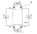
- FIG. 1 is a diagram in which a positive electrode (left side) and a negative electrode (right side) are extracted and arranged from the power storage device B1 according to the first embodiment of the present invention.
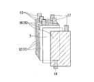
- FIG. 2 is a diagram schematically illustrating the configuration of the assembled power storage device B1 as an example, assuming a case where it is applied to a lithium ion battery device.
- the power storage element B1 includes a sheet-like positive electrode current collector 11 and a negative electrode current collector 15 that are arranged side by side in the thickness direction, and a separator (non-conductive) sandwiched between the positive electrode current collector 11 and the negative electrode current collector 15. And three electrode terminals (first terminal 13, second terminal 17, and third terminal 14).
- a positive electrode active material layer 12 and a negative electrode active material layer 16 are formed on the surfaces (preferably the entire main surface) of the positive electrode current collector 11 and the negative electrode current collector 15, respectively.
- the positive electrode includes the positive electrode current collector 11 and the positive electrode active material layer 12
- the negative electrode includes the negative electrode current collector 15 and the negative electrode active material layer 16.
- the first terminal (positive electrode terminal) 13 is connected to the outer periphery (here, the upper left end portion) of the positive electrode current collector 11.
- the second terminal (negative electrode terminal) 17 is connected to the outer periphery (upper right end portion) of the negative electrode current collector 15.
- the third terminal 14 is connected to at least one of the positive electrode current collector 11 and the negative electrode current collector 15 (here, the lower right end of the positive electrode current collector 11).
- the first terminal 13, the second terminal 17, and the third terminal 14 are provided so as not to overlap each other in a plan view from the thickness direction of the positive electrode current collector 11 and the negative electrode current collector 15.
- the third terminal 14 has a first terminal 13 or a second terminal 17 around a central axis C connecting the centers of the positive electrode current collector 11 and the negative electrode current collector 15 in a plan view from the thickness direction. It is preferable that they are arranged so as to be axially symmetric.
- the active material constituting the positive electrode active material layer 12 for example, it is preferable to use a material having a spinel structure, an olivine structure, or a perovskite structure whose crystal structure does not change depending on the lithium ion content. The crystal structure is maintained even during overcharge or overdischarge, and safety is enhanced.
- the active material for constituting the negative electrode active material layer 16 carbon, graphite, carbon material such as the LTO (lithium-titanium oxide Li 4 Ti 5 O 12) or the like having a spinel structure, an overvoltage condition of the battery An active material that does not emit smoke or ignite can be used.
- the first terminal 13 and the second terminal 17 are connected to a power source 8 such as a power generator without passing through a changeover switch. Further, in the power storage element B1, the second terminal 17 and the third terminal 14 are connected to the load 9 without passing through the changeover switch. That is, in the electricity storage element B1, it is possible to realize a state in which both the charging circuit to which the power source 8 is connected and the discharging circuit to which the load 9 is connected are simultaneously conducted. Accordingly, the storage element B1 is discharged (powered) to the load 9 through the negative electrode terminal 17 and the third terminal 14 simultaneously while being charged by the power source 8 through the positive electrode terminal 13 and the negative electrode terminal 17. It can be carried out.
- the supply voltage (discharge voltage) to the load 9 is kept stable even if the supply voltage (charge voltage) of the power supply 8 varies. This is because an active material layer (here, the positive electrode active material layer 12) is interposed between the first terminal 13 and the third terminal 14, and the voltage fluctuation is attenuated there.
- an active material layer here, the positive electrode active material layer 12
- the potential of the positive electrode of the storage element B1 varies depending on the content of conductive ions (lithium ions) contained in the positive electrode active material 12. That is, the potential of the positive electrode of the electricity storage element B1 is limited by the amount of movement of the conduction ions regardless of the external charging voltage. That is, even if the charging voltage at the first terminal 13 varies, the voltage variation attenuates while propagating through the movement of the conductive ions in the positive electrode active material 12. As a result, voltage fluctuations reaching the third terminal 14 are suppressed, and the discharge voltage becomes constant.
- the electrode potential also depends on the difference between the impedance of the storage element B1 and the impedance of the power source 8.
- the impedance of power supply 8 is preferably higher than the impedance of power storage element B1.
- the fluctuation amount of the charging voltage supplied through the thin wiring is reduced in the power storage element B1 having a sufficiently wide region.
- independent (separate) electrode terminals are provided for charge input and charge output. Therefore, the fluctuating voltage and fluctuating current input at the electrode terminal for charge input are relaxed when lithium ions in the active material layer move to the anode, and the fluctuating voltage, It is output as a true voltage that is not affected by the fluctuation current. With this structure, it is possible to charge from the input terminal even when the generated current is very small, and it is possible to supply a current with very little voltage fluctuation from the output terminal.
- the potential difference between the positive and negative electrodes changes depending on the state of charge.
- the variation range of this potential difference varies depending on the type of active material used. For example, when lithium manganate is used for the positive electrode and graphite is used for the negative electrode, the potential difference fluctuation range is approximately 3 V to 4.2 V.
- the initial terminal voltage is 3V and a voltage of 3.5V is applied to the input terminal
- the storage element B1 is slowly charged, and the output terminal voltage slowly rises from 3V to 3.5V. It becomes a constant voltage at 5V. Since the storage element B1 using lithium manganate for the positive electrode has a stable crystal structure, it can output the same amount of current as the input current from the output terminal.
- the main surfaces of the positive electrode current collector 11 and the negative electrode current collector 15 are preferably rectangular, and more preferably have the same area.
- the first terminal 13, the second terminal 17, and the third terminal 14 are preferably separated from each other.
- the side where the third terminal 14 is provided among the four sides constituting the rectangle it is preferable that the first terminal 13 and the second terminal 17 are connected to different sides.
- first terminal 13 and the third terminal 14 exemplify a case where the first terminal 13 and the third terminal 14 are provided in the vicinity of two vertices on a diagonal line on the rectangular main surface of the positive electrode current collector 11. Yes.
- the first terminal 13 and the third terminal 14 do not have to overlap in plan view from the direction perpendicular to the main surface.
- the rectangular main surface of the positive electrode current collector 11 may be provided near two vertices on the same side.
- the third terminal 14 is connected to the outer periphery of the positive electrode current collector 11
- the third terminal 14 is connected to the outer periphery of the negative electrode current collector 15. It may be.
- the first terminal 13 and the second terminal 17 are connected to the power source 8, and the first terminal 13 and the third terminal 14 are connected to the load 9.
- the limitation on the positional relationship between the first terminal 13 and the third terminal 14 is the same as that when connected to the outer periphery of the positive electrode current collector 11.
- the storage battery stores a necessary number (plural) of storage elements B1 in a battery container together with an electrolyte solution or a solid electrolyte according to a required capacity.
- a storage battery is formed by sealing the battery container.
- the plurality of first terminals 13, the plurality of second terminals 17, and the plurality of third terminals 14 each form a group, and at least a part (tip portion) is drawn out of the battery container. .
- FIG. 3A and 3B are exploded views schematically showing a configuration example of a laminated storage battery including the storage element B1 of FIG.
- FIG. 3A the layers of the positive electrode current collector 11, the negative electrode current collector 15, and the separator 7 constituting the laminate type storage battery are separated and arranged in the order of lamination.
- FIG. 3B the layers of the laminate films 19A and 19B constituting the laminate type storage battery are separated and shown side by side.
- the electricity storage element B1 is formed by alternately stacking (superimposing) layers of a plurality of positive electrode current collectors 11 and negative electrode current collectors 15 with separators 7 interposed therebetween as shown in FIG. 3A.
- the uppermost layer and the lowermost layer of the laminated power storage element B1 are covered with aluminum laminate films 19A and 19B shown in FIG. 5B, and are stored in a battery container together with an electrolyte solution.
- a type storage battery can be obtained.
- the charging circuit and the discharging circuit are separately formed with a simple configuration having three electrode terminals. Since the active material layer is interposed between the two circuits, even if the voltage input from the charging circuit fluctuates, the fluctuation is caused by the rectifying action in the active material layer. The influence on the output voltage can be kept low. Therefore, the storage element B1 according to the present embodiment and the storage battery using the storage element B1 have a simple configuration that does not require a significant increase in cost, and stable discharge with suppressed voltage fluctuation even during charging. It can be performed.
- the power storage element B1 and the storage battery according to the present embodiment are applied to a power supply system that combines power generation and storage using natural energy, a voltage stabilization circuit and a switching circuit for power supply switching are unnecessary, and the system is inexpensive. Can be configured.
- the storage element B1 and the storage battery according to the present embodiment do not exclude the use of a converter or an inverter for adjusting the generated voltage to a desired voltage.
- the power storage target is not limited to natural power generation such as solar power generation, wind power generation, tidal current / tidal power generation, and any power source whose supply voltage fluctuates is included.
- FIG. 4 is a diagram in which the positive electrode (left side) and the negative electrode (right side) are extracted and arranged from the electricity storage device B2 according to the second embodiment of the present invention.
- FIG. 5 is a diagram schematically illustrating the configuration of the assembled power storage device B2 as an example, assuming a case where it is applied to a lithium ion battery device.
- the third terminal 14 is connected to one outer periphery of the positive electrode current collector 11 and the negative electrode current collector 15, and the fourth terminal 18 is connected to the other outer periphery.
- the fourth terminal 18 is provided so as not to overlap the first terminal 13, the second terminal 17, and the third terminal 14. It has been.
- the first terminal 13, the second terminal 17, the third terminal 14, and the fourth terminal 18 are respectively in a rectangular main surface of the positive electrode current collector 11 or the negative electrode current collector 15. The case where it is connected to four vertex vicinity is illustrated.
- the first terminal 13 and the third terminal 14 are respectively connected to the vicinity of two vertices on the diagonal line on the rectangular main surface of the positive electrode current collector 11.
- the second terminal 17 and the fourth terminal 18 are respectively connected to the vicinity of two vertices on the diagonal line on the rectangular main surface of the negative electrode current collector 15.
- the positive terminal 13 and the negative terminal 17 are connected to the power source 8, and the third terminal 14 and the fourth terminal 18 are connected to the load 9.
- first terminal 13, the second terminal 17, the third terminal 14, and the fourth terminal 18 do not have to overlap in plan view from the direction perpendicular to the main surface. It is not limited to the arrangement at.
- FIG. 5 illustrates two types of circuits for connecting the power supply 8 and the load 9.
- the first terminal 13 and the second terminal 17 are connected to the power source 8, and the third terminal 14 and the fourth terminal 18 are connected to the load 9.
- the first terminal 13 and the fourth terminal 18 are connected to the power supply 8, and the third terminal 14 and the second terminal 17 are connected to the load 9. Similar effects can be obtained by using either circuit.
- one of the two terminals connected to the power supply 8 is a common terminal with one of the two terminals connected to the load 9.
- the two terminals connected to the power supply 8 and the two terminals connected to the load 9 are completely separate terminals, and the influence of power fluctuations of the power supply 8 reaches the load 9. , Can be suppressed more.
- a storage battery is formed by storing a necessary number (plural) of storage elements B2 in a battery container together with an electrolyte solution or a solid electrolyte according to a required capacity, and sealing the battery container.
- the plurality of first terminals 13, the plurality of second terminals 17, the plurality of third terminals 14, and the plurality of fourth terminals 18 each form a group, and at least a part (tip portion) is a battery container. Has been pulled out of.
- FIG. 6 is a diagram in which the positive electrode (left side) and the negative electrode (right side) are extracted and arranged from the electricity storage device B3 according to the third embodiment of the present invention.
- FIG. 7 is a diagram schematically showing, as an example, the configuration of the assembled power storage device B3, assuming a case where it is applied to a lithium ion battery device.
- the main surfaces of the positive electrode current collector 11 and the negative electrode current collector 15 are rectangular, and of the four sides constituting the rectangle, the side where the first terminal 13 is provided, or the second terminal
- the third terminal 14 is provided on the same side as the side on which 17 is provided. 6 and 7, on the outer periphery of the positive electrode current collector 11, the first terminal 13 is connected to one end (left end) of the same side (upper side), and the third terminal 14 is connected to the other end (right end). The case where it is done is illustrated.
- the separation distance between the input terminal (first terminal 13 or second terminal 17) and the output terminal (third terminal 14) is If it is short, the influence of the power fluctuation (noise current) of the power supply 8 on the load 9 may be exerted.
- the input terminal and the output terminal are provided sufficiently apart from each other.
- the preferable separation distance between the input terminal and the output terminal is preferably a predetermined distance or more.
- the active material layer between them may be peeled off. Even when the active material layer is peeled off, it is preferable that power fluctuation (noise current) can be sufficiently suppressed.
- the noise absorption capability is a ratio R1 / R1 ′ between a resistance R1 in a region where an active material layer between terminals is formed and a resistance R1 ′ in a region where no active material layer is formed (active material layer non-forming region).
- the resistor R1 is a combined resistance of the internal resistance of the active material layer and the internal resistance of the current collector (metal).
- the resistance R1 ′ is obtained by ⁇ ′ ⁇ L ′ / A ′.
- ⁇ ′ is the specific resistance of the current collector (the positive electrode current collector 11 or the negative electrode current collector 15)
- L ′ is the length between the terminals passing through the exposed current collector when the active material layer is peeled off.
- A is the cross-sectional area of the exposed current collector. A varies depending on the exposed width of the active material layer.
- the amount of current flowing in the active material layer is large when the active material layer is interposed in the propagation of the input current.
- the resistance R1 of the active material layer formation region needs to be larger than the resistance R1 'of the active material layer non-formation region. Therefore, even when the active material layer is peeled off with a width of 0.1 mm between the two terminals, the noise absorption capability R1 / R1 'is preferably 1 or less, and more preferably 0.2 or less.
- variety from which the active material peeled here means the width
- the current collector is made of aluminum (volume resistivity is 2.8 ⁇ cm), the thickness of the current collector is 20 ⁇ m, the number of electrodes (total number of positive and negative electrodes) is 30, and the active material layer between the input and output terminals
- the width of the non-formation region is 1 mm
- the resistance between the input and output terminals is 4.7 m ⁇
- the noise level is attenuated to about 30%.
- the width of the active material layer non-formation region is 2 mm
- the noise level is attenuated to about 20%.
- the noise level is attenuated to about 10%.
- the third terminal 14 is also provided when the fourth terminal 18 is provided on the same side as the side where the first terminal 13 is provided or the side where the second terminal 17 is provided.
- the ratio R2 / R2 ′ can be defined.
- R2 / R2 ' is preferably 1 or less, and more preferably 0.2 or less.
- R2 is the resistance of the region where the active material layer between the terminals is formed, and the resistance of the region where the R2 'active material layer is not formed (active material layer non-forming region).
- FIG. 8 is a diagram in which the positive electrode (upper side) and the negative electrode (lower side) are extracted and arranged from the electricity storage device B4 according to the fourth embodiment of the present invention.
- FIG. 9 is a diagram schematically showing, as an example, the configuration of the assembled power storage device B4, assuming a case where it is applied to a lithium ion battery device.
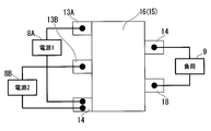
- a plurality of (here, two) first terminals 13A and 13B connected to the power source and one third terminal 14 connected to the load are connected to the outer periphery of the positive electrode current collector 11.
- a second terminal 17 connected to the power source and a fourth terminal 18 connected to the load are connected to the outer periphery of the negative electrode current collector 15.
- the main surface of the positive electrode current collector 11 is rectangular, and among the four sides constituting the rectangle, the first terminals 13A and 13B are provided in one side portion, and the third side is provided in the other side portion.
- the case where the terminal 14 is provided is illustrated.
- the main surface of the negative electrode current collector 15 is rectangular, and among the four sides constituting the rectangle, the second terminal 17 is provided in one side portion, and the fourth terminal 18 is provided in the other side portion. The case where is provided is illustrated.
- the first terminal 13A and the second terminal 17 are connected to the first power supply 8A, the first terminal 13B and the second terminal 17 are connected to the second power supply 8B, and the third terminal 14 and the fourth terminal 18 are connected to the load 9.
- the third terminal 14 includes the first terminals 13 ⁇ / b> A and 13 ⁇ / b> B, the second terminal 17, and the fourth terminal.
- the terminals 18 are provided so as not to overlap each other.
- FIG. 10 is a diagram in which the positive electrode (upper side) and the negative electrode (lower side) are extracted and arranged from the electric storage element B5 according to the fifth embodiment of the present invention.
- FIG. 11 is a diagram schematically showing, as an example, the configuration of the assembled power storage device B5 assuming a case where it is applied to a cylindrical lithium ion battery device.
- a plurality (here, three) of first terminals 13A, 13B, 13C connected to the power source and a plurality (here, three) of first terminals 13A, 13B, 13C connected to the power source are provided on the outer periphery of the positive electrode current collector 11.
- 3 terminals 14A, 14B, 14C are connected.
- a plurality (three in this case) of second terminals 17A, 17B, and 17C are connected to the outer periphery of the negative electrode current collector 15.
- the main surface of the positive electrode current collector 11 is rectangular, and among the four sides constituting the rectangle, the first terminals 13A, 13B, and 13C are provided on one side part, and the other side part is provided on the other side part.
- the case where the third terminals 14A, 14B, and 14C are provided is illustrated.
- the case where the main surface of the negative electrode current collector 15 is rectangular and the second terminals 17A, 17B, and 17C are provided on one side of the four sides forming the rectangle is illustrated. .
- the first terminals 13A, 13B, and 13C are connected in parallel to one end of the power source 8, and the second terminals 17A, 17B, and 17C are connected in parallel to the other end of the power source 8. Further, the third terminals 14A, 14B, and 14C are connected in parallel to one end of the load 9, and the second terminals 17A, 17B, and 17C are connected in parallel to the other end of the load.
- the third terminals 14A, 14B, and 14C may be provided on the negative electrode current collector 15, and in this case, the first terminals 13A, 13B, and 13C are connected in parallel to the other end of the load. .
- the third terminals 14A, 14B, 14C are the first terminals 13A, 13B, 13C, second The terminals 17A, 17B, and 17C are provided so as not to overlap each other.
- FIG. 12 is a diagram schematically showing a configuration of a cylindrical dry battery including the storage element B5 of FIG.
- the cylindrical storage battery is wound in a roll shape so that the inner side becomes the positive electrode current collector 11 and the outer side becomes the negative electrode current collector 15.
- the outermost periphery of the wound wound body is protected by a separator 7. Both ends in the winding axis direction of the wound body are sandwiched between insulators 21. These are housed in a cylindrical metal container 20.
- 1st terminal 13 (13A, 13B, 13C) is connected to the positive electrode cap attached via the insulating ring 25 with respect to the ring-shaped connection part 22 provided in the upper part of the metal containers 20.
- FIG. The second terminals 17 (17A, 17B, 17C) are connected to the bottom of the metal container 20.
- the third terminal 14 is connected to a ring-shaped connection portion attached via an insulating ring 23 provided on the upper edge portion of the metal container 20.
- FIG. 13 is a diagram in which the positive electrode (upper side) and the negative electrode (lower side) are extracted and arranged from the electric storage element B6 according to the fifth embodiment of the present invention.
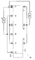
- FIG. 14 is a diagram schematically illustrating a connection example of the power storage element B6, assuming a case where the present invention is applied to a cylindrical lithium ion battery element.
- a plurality (three in this case) of fourth terminals 18A, 18B, and 18C connected to a load are connected to the outer periphery of the negative electrode current collector 15.
- the main surface of the negative electrode current collector 15 is rectangular, and among the four sides constituting the rectangle, the second terminal 17 is connected to one side portion, and the fourth terminal is connected to the other side portion.
- the case where 18A, 18B, and 18C are connected is illustrated.
Landscapes
- Chemical & Material Sciences (AREA)
- Chemical Kinetics & Catalysis (AREA)
- Electrochemistry (AREA)
- General Chemical & Material Sciences (AREA)
- Engineering & Computer Science (AREA)
- Manufacturing & Machinery (AREA)
- Materials Engineering (AREA)
- Power Engineering (AREA)
- Composite Materials (AREA)
- Microelectronics & Electronic Packaging (AREA)
- Secondary Cells (AREA)
- Sealing Battery Cases Or Jackets (AREA)
- Cell Electrode Carriers And Collectors (AREA)
- Connection Of Batteries Or Terminals (AREA)
Priority Applications (6)
| Application Number | Priority Date | Filing Date | Title |
|---|---|---|---|
| PCT/JP2018/022805 WO2019239560A1 (ja) | 2018-06-14 | 2018-06-14 | 蓄電素子とそれを用いた蓄電池 |
| KR1020207004015A KR20210019396A (ko) | 2018-06-14 | 2019-06-12 | 축전 소자, 축전지 및 축방전 시스템 |
| JP2020525626A JP7072925B2 (ja) | 2018-06-14 | 2019-06-12 | 蓄電素子、蓄電池及び蓄放電システム |
| US16/644,580 US20210098793A1 (en) | 2018-06-14 | 2019-06-12 | Power storage element, power storage cell, and power storage and discharge system |
| PCT/JP2019/023319 WO2019240183A1 (ja) | 2018-06-14 | 2019-06-12 | 蓄電素子、蓄電池及び蓄放電システム |
| CN201980004184.XA CN112204812A (zh) | 2018-06-14 | 2019-06-12 | 蓄电元件、蓄电池及蓄放电系统 |
Applications Claiming Priority (1)
| Application Number | Priority Date | Filing Date | Title |
|---|---|---|---|
| PCT/JP2018/022805 WO2019239560A1 (ja) | 2018-06-14 | 2018-06-14 | 蓄電素子とそれを用いた蓄電池 |
Publications (1)
| Publication Number | Publication Date |
|---|---|
| WO2019239560A1 true WO2019239560A1 (ja) | 2019-12-19 |
Family
ID=68842960
Family Applications (2)
| Application Number | Title | Priority Date | Filing Date |
|---|---|---|---|
| PCT/JP2018/022805 Ceased WO2019239560A1 (ja) | 2018-06-14 | 2018-06-14 | 蓄電素子とそれを用いた蓄電池 |
| PCT/JP2019/023319 Ceased WO2019240183A1 (ja) | 2018-06-14 | 2019-06-12 | 蓄電素子、蓄電池及び蓄放電システム |
Family Applications After (1)
| Application Number | Title | Priority Date | Filing Date |
|---|---|---|---|
| PCT/JP2019/023319 Ceased WO2019240183A1 (ja) | 2018-06-14 | 2019-06-12 | 蓄電素子、蓄電池及び蓄放電システム |
Country Status (5)
| Country | Link |
|---|---|
| US (1) | US20210098793A1 (https=) |
| JP (1) | JP7072925B2 (https=) |
| KR (1) | KR20210019396A (https=) |
| CN (1) | CN112204812A (https=) |
| WO (2) | WO2019239560A1 (https=) |
Cited By (1)
| Publication number | Priority date | Publication date | Assignee | Title |
|---|---|---|---|---|
| JPWO2024225439A1 (https=) * | 2023-04-28 | 2024-10-31 |
Families Citing this family (6)
| Publication number | Priority date | Publication date | Assignee | Title |
|---|---|---|---|---|
| CN110010902A (zh) | 2019-03-29 | 2019-07-12 | 宁德新能源科技有限公司 | 电极极片和包含所述电极极片的电化学装置 |
| CN109980177B (zh) * | 2019-03-29 | 2021-10-22 | 东莞新能安科技有限公司 | 电极极片和包含所述电极极片的电化学装置 |
| JP7778484B2 (ja) * | 2021-03-04 | 2025-12-02 | 株式会社東芝 | 乾燥装置及び乾燥方法 |
| JP7781384B2 (ja) * | 2021-03-30 | 2025-12-08 | 国立大学法人 筑波大学 | 三次電池、IoT機器 |
| CN116706441A (zh) * | 2022-02-25 | 2023-09-05 | 宁德时代新能源科技股份有限公司 | 电池单体、电池和用电设备 |
| CN117638392B (zh) * | 2022-08-19 | 2025-02-11 | 比亚迪股份有限公司 | 单体电池、电池包和车辆 |
Citations (4)
| Publication number | Priority date | Publication date | Assignee | Title |
|---|---|---|---|---|
| JPH10233201A (ja) * | 1997-02-17 | 1998-09-02 | Sanyo Electric Co Ltd | 角型蓄電池 |
| WO2011099620A1 (ja) * | 2010-02-15 | 2011-08-18 | 三菱重工業株式会社 | 二次電池および二次電池製造装置 |
| JP2012204305A (ja) * | 2011-03-28 | 2012-10-22 | Mitsubishi Heavy Ind Ltd | 電池セル |
| JP2017107869A (ja) * | 2009-11-30 | 2017-06-15 | 楊 泰和 | 蓄電及び給電装置 |
Family Cites Families (12)
| Publication number | Priority date | Publication date | Assignee | Title |
|---|---|---|---|---|
| JPH1167188A (ja) * | 1997-08-22 | 1999-03-09 | Japan Storage Battery Co Ltd | 二次電池用リード端子及びリチウム二次電池 |
| JP2001319839A (ja) * | 2000-05-11 | 2001-11-16 | Nobuo Ashitachi | 大容量コンデンサ |
| JP2002289168A (ja) * | 2001-03-27 | 2002-10-04 | Shin Kobe Electric Mach Co Ltd | 制御弁式鉛蓄電池 |
| US6806679B2 (en) * | 2001-06-20 | 2004-10-19 | Tai-Her Yang | Low internal impedance current pool for a charging/discharging device |
| AU2006300857A1 (en) * | 2005-10-12 | 2007-04-19 | Jan Human | Electrical storage device |
| CN2916941Y (zh) * | 2006-03-02 | 2007-06-27 | 夏伟绩 | 双极耳蓄电池 |
| JP4928215B2 (ja) | 2006-10-10 | 2012-05-09 | ジオ・システムズ株式会社 | 屋外監視装置及び映像監視システム |
| US20100035105A1 (en) * | 2006-12-21 | 2010-02-11 | Jan Petrus Human | Electrical storage device |
| KR20130091031A (ko) | 2012-02-07 | 2013-08-16 | 에스케이이노베이션 주식회사 | 배터리 셀 |
| JP6340536B2 (ja) | 2013-09-25 | 2018-06-13 | 株式会社 シリコンプラス | 自立型監視カメラ |
| PL2899769T3 (pl) * | 2013-11-27 | 2019-09-30 | Lg Chem, Ltd. | Kieszeń od akumulatora i akumulator ją zawierający |
| CN107666006A (zh) * | 2016-07-28 | 2018-02-06 | 华为技术有限公司 | 一种多极耳电池及终端 |
-
2018
- 2018-06-14 WO PCT/JP2018/022805 patent/WO2019239560A1/ja not_active Ceased
-
2019
- 2019-06-12 JP JP2020525626A patent/JP7072925B2/ja not_active Expired - Fee Related
- 2019-06-12 WO PCT/JP2019/023319 patent/WO2019240183A1/ja not_active Ceased
- 2019-06-12 US US16/644,580 patent/US20210098793A1/en not_active Abandoned
- 2019-06-12 KR KR1020207004015A patent/KR20210019396A/ko not_active Withdrawn
- 2019-06-12 CN CN201980004184.XA patent/CN112204812A/zh active Pending
Patent Citations (4)
| Publication number | Priority date | Publication date | Assignee | Title |
|---|---|---|---|---|
| JPH10233201A (ja) * | 1997-02-17 | 1998-09-02 | Sanyo Electric Co Ltd | 角型蓄電池 |
| JP2017107869A (ja) * | 2009-11-30 | 2017-06-15 | 楊 泰和 | 蓄電及び給電装置 |
| WO2011099620A1 (ja) * | 2010-02-15 | 2011-08-18 | 三菱重工業株式会社 | 二次電池および二次電池製造装置 |
| JP2012204305A (ja) * | 2011-03-28 | 2012-10-22 | Mitsubishi Heavy Ind Ltd | 電池セル |
Cited By (2)
| Publication number | Priority date | Publication date | Assignee | Title |
|---|---|---|---|---|
| JPWO2024225439A1 (https=) * | 2023-04-28 | 2024-10-31 | ||
| JP7835956B2 (ja) | 2023-04-28 | 2026-03-25 | 興和株式会社 | 蓄放電システム、及び蓄電素子 |
Also Published As
| Publication number | Publication date |
|---|---|
| US20210098793A1 (en) | 2021-04-01 |
| KR20210019396A (ko) | 2021-02-22 |
| WO2019240183A1 (ja) | 2019-12-19 |
| JP7072925B2 (ja) | 2022-05-23 |
| CN112204812A (zh) | 2021-01-08 |
| JPWO2019240183A1 (ja) | 2021-07-15 |
Similar Documents
| Publication | Publication Date | Title |
|---|---|---|
| JP7072925B2 (ja) | 蓄電素子、蓄電池及び蓄放電システム | |
| JP5618010B2 (ja) | 多方向性リード−タブ構造を有するリチウム二次電池 | |
| JP5779828B2 (ja) | 段差を有する電極組立体、それを含む電池セル、電池パック及びデバイス | |
| KR101575984B1 (ko) | 전극탭 접합성이 우수한 전극 조립체, 이를 포함하는 전지셀, 디바이스 및 이의 제조방법 | |
| CN102150300B (zh) | 电极体、全固体型电池元件及全固体型电池 | |
| US11121439B2 (en) | Secondary battery | |
| TWI535090B (zh) | Secondary battery | |
| KR20130118716A (ko) | 전극 조립체, 이를 포함하는 전지셀 및 디바이스 | |
| US20060208692A1 (en) | Hybrid rechargeable battery having high power and high energy density lithium cells | |
| JP2004158222A (ja) | 多層積層電池 | |
| JP2000100471A (ja) | シート電池 | |
| TWI546997B (zh) | Lithium ion secondary battery | |
| JPWO2019240183A5 (https=) | ||
| JP7312970B2 (ja) | 電池 | |
| JP2005267886A (ja) | 二次電池 | |
| US11189889B2 (en) | Rechargeable battery | |
| JP2000195495A (ja) | シ―ト電池 | |
| CN111492526B (zh) | 电极组件、二次电池和二次电池模块 | |
| KR20140017766A (ko) | 이차 전지 | |
| KR101416805B1 (ko) | 폴딩 셀 및 그를 갖는 폴딩형 슈퍼 커패시터 | |
| JPH0963630A (ja) | 電気蓄積素子、電気蓄積装置および電気蓄積素子の製造方法 | |
| CN107978761B (zh) | 用于存储电能的蓄能电池的集电器 | |
| KR101416806B1 (ko) | 폴딩 셀 및 그를 갖는 폴딩형 슈퍼 커패시터 | |
| WO2018154926A1 (ja) | 蓄電シート及び電池 | |
| WO2018154927A1 (ja) | 糸状電池 |
Legal Events
| Date | Code | Title | Description |
|---|---|---|---|
| 121 | Ep: the epo has been informed by wipo that ep was designated in this application |
Ref document number: 18922892 Country of ref document: EP Kind code of ref document: A1 |
|
| NENP | Non-entry into the national phase |
Ref country code: DE |
|
| 122 | Ep: pct application non-entry in european phase |
Ref document number: 18922892 Country of ref document: EP Kind code of ref document: A1 |
|
| NENP | Non-entry into the national phase |
Ref country code: JP |