WO2019239531A1 - 演算装置、検出システム、造形装置、演算方法、検出方法、造形方法、演算プログラム、検出プログラムおよび造形プログラム - Google Patents
演算装置、検出システム、造形装置、演算方法、検出方法、造形方法、演算プログラム、検出プログラムおよび造形プログラム Download PDFInfo
- Publication number
- WO2019239531A1 WO2019239531A1 PCT/JP2018/022622 JP2018022622W WO2019239531A1 WO 2019239531 A1 WO2019239531 A1 WO 2019239531A1 JP 2018022622 W JP2018022622 W JP 2018022622W WO 2019239531 A1 WO2019239531 A1 WO 2019239531A1
- Authority
- WO
- WIPO (PCT)
- Prior art keywords
- material layer
- modeling
- unit
- powder material
- temperature
- Prior art date
- Legal status (The legal status is an assumption and is not a legal conclusion. Google has not performed a legal analysis and makes no representation as to the accuracy of the status listed.)
- Ceased
Links
Images


Classifications
-
- B—PERFORMING OPERATIONS; TRANSPORTING
- B29—WORKING OF PLASTICS; WORKING OF SUBSTANCES IN A PLASTIC STATE IN GENERAL
- B29C—SHAPING OR JOINING OF PLASTICS; SHAPING OF MATERIAL IN A PLASTIC STATE, NOT OTHERWISE PROVIDED FOR; AFTER-TREATMENT OF THE SHAPED PRODUCTS, e.g. REPAIRING
- B29C64/00—Additive manufacturing, i.e. manufacturing of three-dimensional [3D] objects by additive deposition, additive agglomeration or additive layering, e.g. by 3D printing, stereolithography or selective laser sintering
- B29C64/10—Processes of additive manufacturing
- B29C64/141—Processes of additive manufacturing using only solid materials
- B29C64/153—Processes of additive manufacturing using only solid materials using layers of powder being selectively joined, e.g. by selective laser sintering or melting
-
- B—PERFORMING OPERATIONS; TRANSPORTING
- B22—CASTING; POWDER METALLURGY
- B22F—WORKING METALLIC POWDER; MANUFACTURE OF ARTICLES FROM METALLIC POWDER; MAKING METALLIC POWDER; APPARATUS OR DEVICES SPECIALLY ADAPTED FOR METALLIC POWDER
- B22F10/00—Additive manufacturing of workpieces or articles from metallic powder
- B22F10/20—Direct sintering or melting
- B22F10/28—Powder bed fusion, e.g. selective laser melting [SLM] or electron beam melting [EBM]
-
- B—PERFORMING OPERATIONS; TRANSPORTING
- B22—CASTING; POWDER METALLURGY
- B22F—WORKING METALLIC POWDER; MANUFACTURE OF ARTICLES FROM METALLIC POWDER; MAKING METALLIC POWDER; APPARATUS OR DEVICES SPECIALLY ADAPTED FOR METALLIC POWDER
- B22F10/00—Additive manufacturing of workpieces or articles from metallic powder
- B22F10/30—Process control
- B22F10/32—Process control of the atmosphere, e.g. composition or pressure in a building chamber
- B22F10/322—Process control of the atmosphere, e.g. composition or pressure in a building chamber of the gas flow, e.g. rate or direction
-
- B—PERFORMING OPERATIONS; TRANSPORTING
- B22—CASTING; POWDER METALLURGY
- B22F—WORKING METALLIC POWDER; MANUFACTURE OF ARTICLES FROM METALLIC POWDER; MAKING METALLIC POWDER; APPARATUS OR DEVICES SPECIALLY ADAPTED FOR METALLIC POWDER
- B22F10/00—Additive manufacturing of workpieces or articles from metallic powder
- B22F10/30—Process control
- B22F10/34—Process control of powder characteristics, e.g. density, oxidation or flowability
-
- B—PERFORMING OPERATIONS; TRANSPORTING
- B22—CASTING; POWDER METALLURGY
- B22F—WORKING METALLIC POWDER; MANUFACTURE OF ARTICLES FROM METALLIC POWDER; MAKING METALLIC POWDER; APPARATUS OR DEVICES SPECIALLY ADAPTED FOR METALLIC POWDER
- B22F10/00—Additive manufacturing of workpieces or articles from metallic powder
- B22F10/30—Process control
- B22F10/36—Process control of energy beam parameters
- B22F10/366—Scanning parameters, e.g. hatch distance or scanning strategy
-
- B—PERFORMING OPERATIONS; TRANSPORTING
- B22—CASTING; POWDER METALLURGY
- B22F—WORKING METALLIC POWDER; MANUFACTURE OF ARTICLES FROM METALLIC POWDER; MAKING METALLIC POWDER; APPARATUS OR DEVICES SPECIALLY ADAPTED FOR METALLIC POWDER
- B22F10/00—Additive manufacturing of workpieces or articles from metallic powder
- B22F10/30—Process control
- B22F10/36—Process control of energy beam parameters
- B22F10/368—Temperature or temperature gradient, e.g. temperature of the melt pool
-
- B—PERFORMING OPERATIONS; TRANSPORTING
- B22—CASTING; POWDER METALLURGY
- B22F—WORKING METALLIC POWDER; MANUFACTURE OF ARTICLES FROM METALLIC POWDER; MAKING METALLIC POWDER; APPARATUS OR DEVICES SPECIALLY ADAPTED FOR METALLIC POWDER
- B22F10/00—Additive manufacturing of workpieces or articles from metallic powder
- B22F10/30—Process control
- B22F10/37—Process control of powder bed aspects, e.g. density
-
- B—PERFORMING OPERATIONS; TRANSPORTING
- B22—CASTING; POWDER METALLURGY
- B22F—WORKING METALLIC POWDER; MANUFACTURE OF ARTICLES FROM METALLIC POWDER; MAKING METALLIC POWDER; APPARATUS OR DEVICES SPECIALLY ADAPTED FOR METALLIC POWDER
- B22F10/00—Additive manufacturing of workpieces or articles from metallic powder
- B22F10/80—Data acquisition or data processing
- B22F10/85—Data acquisition or data processing for controlling or regulating additive manufacturing processes
-
- B—PERFORMING OPERATIONS; TRANSPORTING
- B22—CASTING; POWDER METALLURGY
- B22F—WORKING METALLIC POWDER; MANUFACTURE OF ARTICLES FROM METALLIC POWDER; MAKING METALLIC POWDER; APPARATUS OR DEVICES SPECIALLY ADAPTED FOR METALLIC POWDER
- B22F12/00—Apparatus or devices specially adapted for additive manufacturing; Auxiliary means for additive manufacturing; Combinations of additive manufacturing apparatus or devices with other processing apparatus or devices
- B22F12/90—Means for process control, e.g. cameras or sensors
-
- B—PERFORMING OPERATIONS; TRANSPORTING
- B23—MACHINE TOOLS; METAL-WORKING NOT OTHERWISE PROVIDED FOR
- B23K—SOLDERING OR UNSOLDERING; WELDING; CLADDING OR PLATING BY SOLDERING OR WELDING; CUTTING BY APPLYING HEAT LOCALLY, e.g. FLAME CUTTING; WORKING BY LASER BEAM
- B23K26/00—Working by laser beam, e.g. welding, cutting or boring
- B23K26/02—Positioning or observing the workpiece, e.g. with respect to the point of impact; Aligning, aiming or focusing the laser beam
- B23K26/03—Observing, e.g. monitoring, the workpiece
- B23K26/034—Observing the temperature of the workpiece
-
- B—PERFORMING OPERATIONS; TRANSPORTING
- B23—MACHINE TOOLS; METAL-WORKING NOT OTHERWISE PROVIDED FOR
- B23K—SOLDERING OR UNSOLDERING; WELDING; CLADDING OR PLATING BY SOLDERING OR WELDING; CUTTING BY APPLYING HEAT LOCALLY, e.g. FLAME CUTTING; WORKING BY LASER BEAM
- B23K26/00—Working by laser beam, e.g. welding, cutting or boring
- B23K26/34—Laser welding for purposes other than joining
- B23K26/342—Build-up welding
-
- B—PERFORMING OPERATIONS; TRANSPORTING
- B29—WORKING OF PLASTICS; WORKING OF SUBSTANCES IN A PLASTIC STATE IN GENERAL
- B29C—SHAPING OR JOINING OF PLASTICS; SHAPING OF MATERIAL IN A PLASTIC STATE, NOT OTHERWISE PROVIDED FOR; AFTER-TREATMENT OF THE SHAPED PRODUCTS, e.g. REPAIRING
- B29C64/00—Additive manufacturing, i.e. manufacturing of three-dimensional [3D] objects by additive deposition, additive agglomeration or additive layering, e.g. by 3D printing, stereolithography or selective laser sintering
- B29C64/30—Auxiliary operations or equipment
- B29C64/386—Data acquisition or data processing for additive manufacturing
- B29C64/393—Data acquisition or data processing for additive manufacturing for controlling or regulating additive manufacturing processes
-
- B—PERFORMING OPERATIONS; TRANSPORTING
- B33—ADDITIVE MANUFACTURING TECHNOLOGY
- B33Y—ADDITIVE MANUFACTURING, i.e. MANUFACTURING OF THREE-DIMENSIONAL [3D] OBJECTS BY ADDITIVE DEPOSITION, ADDITIVE AGGLOMERATION OR ADDITIVE LAYERING, e.g. BY 3D PRINTING, STEREOLITHOGRAPHY OR SELECTIVE LASER SINTERING
- B33Y10/00—Processes of additive manufacturing
-
- B—PERFORMING OPERATIONS; TRANSPORTING
- B33—ADDITIVE MANUFACTURING TECHNOLOGY
- B33Y—ADDITIVE MANUFACTURING, i.e. MANUFACTURING OF THREE-DIMENSIONAL [3D] OBJECTS BY ADDITIVE DEPOSITION, ADDITIVE AGGLOMERATION OR ADDITIVE LAYERING, e.g. BY 3D PRINTING, STEREOLITHOGRAPHY OR SELECTIVE LASER SINTERING
- B33Y30/00—Apparatus for additive manufacturing; Details thereof or accessories therefor
-
- B—PERFORMING OPERATIONS; TRANSPORTING
- B33—ADDITIVE MANUFACTURING TECHNOLOGY
- B33Y—ADDITIVE MANUFACTURING, i.e. MANUFACTURING OF THREE-DIMENSIONAL [3D] OBJECTS BY ADDITIVE DEPOSITION, ADDITIVE AGGLOMERATION OR ADDITIVE LAYERING, e.g. BY 3D PRINTING, STEREOLITHOGRAPHY OR SELECTIVE LASER SINTERING
- B33Y50/00—Data acquisition or data processing for additive manufacturing
- B33Y50/02—Data acquisition or data processing for additive manufacturing for controlling or regulating additive manufacturing processes
-
- G—PHYSICS
- G06—COMPUTING OR CALCULATING; COUNTING
- G06T—IMAGE DATA PROCESSING OR GENERATION, IN GENERAL
- G06T7/00—Image analysis
- G06T7/0002—Inspection of images, e.g. flaw detection
- G06T7/0004—Industrial image inspection
-
- B—PERFORMING OPERATIONS; TRANSPORTING
- B22—CASTING; POWDER METALLURGY
- B22F—WORKING METALLIC POWDER; MANUFACTURE OF ARTICLES FROM METALLIC POWDER; MAKING METALLIC POWDER; APPARATUS OR DEVICES SPECIALLY ADAPTED FOR METALLIC POWDER
- B22F2203/00—Controlling
- B22F2203/03—Controlling for feed-back
-
- B—PERFORMING OPERATIONS; TRANSPORTING
- B22—CASTING; POWDER METALLURGY
- B22F—WORKING METALLIC POWDER; MANUFACTURE OF ARTICLES FROM METALLIC POWDER; MAKING METALLIC POWDER; APPARATUS OR DEVICES SPECIALLY ADAPTED FOR METALLIC POWDER
- B22F2999/00—Aspects linked to processes or compositions used in powder metallurgy
-
- G—PHYSICS
- G06—COMPUTING OR CALCULATING; COUNTING
- G06T—IMAGE DATA PROCESSING OR GENERATION, IN GENERAL
- G06T2207/00—Indexing scheme for image analysis or image enhancement
- G06T2207/30—Subject of image; Context of image processing
- G06T2207/30108—Industrial image inspection
- G06T2207/30144—Printing quality
-
- Y—GENERAL TAGGING OF NEW TECHNOLOGICAL DEVELOPMENTS; GENERAL TAGGING OF CROSS-SECTIONAL TECHNOLOGIES SPANNING OVER SEVERAL SECTIONS OF THE IPC; TECHNICAL SUBJECTS COVERED BY FORMER USPC CROSS-REFERENCE ART COLLECTIONS [XRACs] AND DIGESTS
- Y02—TECHNOLOGIES OR APPLICATIONS FOR MITIGATION OR ADAPTATION AGAINST CLIMATE CHANGE
- Y02P—CLIMATE CHANGE MITIGATION TECHNOLOGIES IN THE PRODUCTION OR PROCESSING OF GOODS
- Y02P10/00—Technologies related to metal processing
- Y02P10/25—Process efficiency
Definitions
- the present invention relates to a calculation device, a detection system, a modeling device, a calculation method, a detection method, a modeling method, a calculation program, a detection program, and a modeling program.
- Patent Document 1 a three-dimensional object manufacturing apparatus that manufactures a three-dimensional object by laminating layers obtained by solidifying a powdery substance by light action or the like is known (for example, Patent Document 1).
- the manufactured object may be defective.
- the arithmetic device used in the modeling apparatus that models the three-dimensional modeled object from the solidified layer that is modeled by heating the layered material layer formed from the powder material by irradiation of the energy beam is formed as described above.
- the calculation method used in the modeling apparatus for modeling the three-dimensional modeled object from the solidified layer modeled by heating the layered material layer formed from the powder material by irradiation with energy rays is formed as described above. In order to determine the state of the material layer based on the shape of the material layer and to set the modeling conditions of the modeling apparatus, information regarding the determined state of the material layer is output.
- the modeling apparatus according to the first embodiment will be described with reference to the drawings.
- a modeling apparatus that models a three-dimensional modeled object (three-dimensional modeled object) using a known powder bed fusion bonding method (PBF) will be described as an example.
- the powder bed fusion bonding method (PBF) is also called a powder sintering additive manufacturing method (SLS).
- the modeling apparatus is not limited to the powder bed fusion bonding method (PBF), but other directivity lamination method (DED), material injection method, electron beam melting method (EBM), thermal melting lamination method (FDM), etc.
- DED directivity lamination method
- EBM electron beam melting method
- FDM thermal melting lamination method
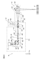
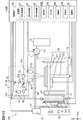
- FIG. 1 is a block diagram schematically illustrating the structure of the modeling apparatus 1
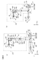
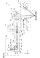
- FIG. 2 is a diagram schematically illustrating an example of a specific configuration and arrangement of the modeling optical unit 35 included in the modeling apparatus 1.
- the following description will be given using an orthogonal coordinate system composed of an X axis, a Y axis, and a Z axis, as shown in FIGS.
- the modeling apparatus 1 includes a housing 10, a material layer forming unit 20, a modeling unit 30, and an arithmetic device 50.
- the material layer forming unit 20 includes a material supply tank 21 and a recoater 22.
- the modeling unit 30 includes a modeling tank 31 and a modeling optical unit 35.
- the material layer forming unit 20 and the modeling unit 30 are separately represented as separate components, but the material layer forming unit 20 and the modeling unit 30 may be collectively expressed as a modeling unit.
- the material supply tank 21 is a storage container for storing a powder material P that is a material for modeling a three-dimensional structure.
- the bottom surface 211 of the material supply tank 21 is moved along the vertical direction (Z direction) by a drive mechanism 212 constituted by, for example, a piston or the like.
- a drive mechanism 212 constituted by, for example, a piston or the like.
- the powder material P inside the material supply tank 21 is pushed out according to the rising amount of the bottom surface 211, and the extruded powder
- the material P is transferred to a modeling tank 31 described later by a recoater 22 described later.
- the material supply tank 21 is provided with a heater 213 for heating the powder material P accommodated therein.
- the heater 213 heats the powder material P so as to have a desired temperature under the control of the arithmetic unit 50 described later.
- a temperature control element such as a Peltier element may be used for the heater 213.
- This heater 213 heats the powder material P in the material supply tank 21, so that the powder material P is transferred to the modeling tank 31 and before the powder material P is heated by laser light irradiation described later, the powder material P Increase the temperature of P.
- the amount of heat required for the temperature of the powder material P heated by the laser light irradiation to rise to a desired temperature is reduced.
- the heater 213 heats the powder material P having high moisture absorption and low fluidity, thereby reducing the moisture absorption of the powder material P and increasing the fluidity.
- the powder material P becomes easy to be transferred to the modeling tank 31, and the flatness, the lamination thickness, and the density of the material layer formed as described in detail later become uniform.
- the temperature rise inside the material layer due to the laser beam irradiation becomes uniform.
- the material supply tank 21 is not limited to what extrudes the powder material P to the exterior with the drive mechanism 212 from the Z direction lower part.
- the powder material P accommodated in the material supply tank 21 is supplied to a dispenser provided below the material supply tank 21 (Z direction ⁇ side), and the powder material P supplied to the dispenser is placed below the dispenser (Z direction ⁇ ).
- the powder material P that has fallen onto the base plate 311 of the modeling tank 31 from the discharge portion provided on the side) may be spread to a uniform thickness by moving a blade 221 included in the recoater 22 described later.
- the powder material P for example, metal powder, resin powder, powder obtained by coating a metal particle with a resin binder, or the like is used.
- the metal powder further includes at least one or more of powders composed mainly of iron-based powders, iron-based powders, nickel powders, nickel-based synthetic powders, copper powders, copper-based alloy powders, graphite-based powders, and the like. Powder may be sufficient.
- the amount of iron-based powder having an average particle size of about 20 ⁇ m is 60 to 90% by weight
- the amount of both nickel powder and nickel-based alloy powder is 5 to 35% by weight
- copper powder and copper-based alloy powder is used as the powder material P.
- Examples thereof include powders in which the amount of both or one is 5 to 15% by weight and the amount of graphite powder is 0.2 to 0.8% by weight.
- the resin powder for example, a powder of polyamide, polypropylene, ABS or the like having an average particle size of about 30 ⁇ m to 100 ⁇ m can be used.
- a powder obtained by coating a metal particle with a resin binder for example, a metal particle whose surface is coated with an additive such as phenol resin or nylon may be used.
- ceramic powder may be used as the powder material P.
- the ceramic powder may be an oxide such as alumina or zirconia, or a nitride powder such as silicon nitride.
- the powder material P may be other than the above materials.
- the powder material P may be, for example, an existing metal powder, an existing resin powder, or an existing ceramic powder, or a powder material in which at least two materials of an existing metal, an existing resin, and an existing ceramic are combined. There may be.
- a metal powder is used as the powder material P will be described as an example.
- the recoater 22 has a blade 221 as a material layer forming member, a drive mechanism (not shown), and a blade mounting portion (not shown).
- the blade 221 is, for example, a plate-like member that extends along the Y direction.
- the blade 221 is attached to the blade mounting portion so as to be exchangeable among a plurality of types having different materials and shapes.
- the drive mechanism has a drive mechanism such as a motor or a guide rail extending along the X direction, for example, and the blade 221 is moved along the X direction by moving the blade mounting portion along the X direction. It is moved between (the X direction-side end of the material supply tank 21) and the position B (X direction + side end of the modeling tank 31).
- the blade 221 By moving the blade 221 in this manner, the powder material P accommodated in the material supply tank 21 (more specifically, the material according to the amount of increase in the Z direction + side (upward) of the bottom surface 211 of the material supply tank 21)
- the powder material P) extruded to the outside of the supply tank 21 is transferred to the modeling tank 31 of the modeling unit 30 described later.
- the blade 221 moves while applying pressure so as to press the powder material P downward (Z direction-side).
- a powder called a powder bed (powder bed) in which the powder material P is spread in the modeling tank 31 with a certain thickness ⁇ d by the movement of the blade 221 and the surface (surface in the Z direction + side) is shaped flat.
- a layer of material (hereinafter referred to as a material layer) is formed. That is, the blade 221 functions as a material layer forming member. Note that the blade 221 can apply pressure to the powder material P by a pressing mechanism (not shown) including a cylinder or the like.
- the solidified layer is formed by irradiating the previously formed material layer with laser light. After a predetermined time has elapsed, the blade 221 moves again from the position A along the X direction, and transfers the powder material P to the upper part of the solidified layer. In the present specification, this predetermined time is referred to as a standby time of the blade 221.
- the above-mentioned constant thickness ⁇ d is the thickness from the surface of the base plate 311 to the surface of the material layer (Z-direction + surface) when the powder material P is transferred onto the base plate 311 described later.
- the powder material P is transferred to the upper part (Z direction + side) of the solidified layer that is shaped as described later, the solidified layer from the upper surface (Z direction + side surface) of the solidified layer It is the thickness to the surface (Z direction + side surface) of the material layer formed in the upper part.
- the moving speed of the blade 221, the pressure applied to the powder material by the blade 221, and the standby time of the blade 221 are controlled by the arithmetic device 50 so as to be changeable. Details of the formation of the material layer will be described later.
- a plate-like blade 221 is described as an example of the material layer forming member.
- the material layer forming member is a member that can be used to form a roller or other material layer.
- the roller when a roller is used as the material layer forming member, the roller is attached so that the rotation axis is along the Y-axis direction, and moves while rotating when the drive mechanism moves along the X direction. Accordingly, the roller spreads the powder material P in the modeling tank 31 with a certain thickness ⁇ d while applying pressure to the powder material P.
- the modeling tank 31 of the modeling unit 30 repeats the formation of the material layer and the modeling of the solidified layer obtained by solidifying the formed material layer, and stacks the plurality of solidified layers along the Z direction to form a three-dimensional shape. It is a container for modeling work for modeling a modeled object.
- the solidified layer in the present embodiment is a layer formed by heating the powder material P that forms the material layer by irradiation with laser light, melting the powder material P by heating, and solidifying it.
- the base plate 311 which is the bottom surface of the modeling tank 31 is a support member that supports the formed material layer and the solidified layer from the Z direction-side.
- the base plate 311 is moved along the vertical direction (Z direction) by a drive mechanism 312 such as a motor included in the modeling tank 31.
- a drive mechanism 312 such as a motor included in the modeling tank 31.
- the base plate 311 moves downward (Z direction-side).
- a new material layer is formed on the upper surface (Z direction + side) of the solidified layer.
- This new material layer is solidified to form a new solidified layer.
- the base plate 311 is attached to the modeling tank 31 so as to be exchangeable between a plurality of types of plates having different materials and thicknesses in the Z direction. In other words, it can be said that the base plate 311 is attached to the modeling tank 31 so as to be exchangeable among a plurality of types of plates having different rigidity.
- the base plate 311 is provided with a heater 313 for heating the base plate 311.
- the heater 313 heats (preheats) the material layer and the solidified layer supported by the base plate 311 at a desired temperature under the control of the arithmetic unit 50 described later.
- the heater 313 heats (preheats) the material layer and the solidified layer in the modeling tank 31.
- the heater 313 preheats the powder material P and raises the temperature before the powder material P constituting the material layer is heated by laser light irradiation.
- the heater 313 heats the solidified layer that has been formed. Thereby, the occurrence of residual stress during cooling of the solidified layer is suppressed, or the residual stress generated in the solidified layer is relieved.
- the modeling optical unit 35 of the modeling unit 30 includes an acquisition unit 310, an irradiation unit 32, a scanning unit 33, and a focus lens 323.
- the acquisition unit 310 includes an imaging device 41, details of which will be described later, a two-branch optical system 42, a chromatic aberration correction optical system 43, a half mirror 301, and a field stop 302.
- the acquisition unit 310 includes a predetermined region including a melted part in which the powder material P is melted (a melted part in which the powder material P is melted, an unmelted powder material P (material layer) that has not yet melted), and solidifies after melting. At least part of the information (details will be described later). Note that the half mirror 301 may not be included in the acquisition unit 310 in accordance with the arrangement of each component of the modeling optical unit 35 described later in detail.
- the acquisition unit 310 since the acquisition unit 310 is configured integrally with the irradiation unit 32 and the scanning unit 33, the acquisition unit 310 will be described as a part of the modeling optical unit 35 (that is, a part of the modeling unit 30) for convenience of explanation.
- the acquisition unit 310 has a function different from the configuration of the modeling unit 30 other than the acquisition unit 310 (that is, the modeling tank 31, the irradiation unit 32, the focus lens 323, and the scanning unit 33). Since it is a structure provided with the function which acquires the information of the at least one part of the predetermined area
- the modeling unit 30 includes a modeling optical unit 35 including the irradiation unit 32, the scanning unit 33, and the focus lens 323, and the modeling tank 31.
- the half mirror 301 is also a part of the modeling optical unit 35, it can be expressed as a configuration of the modeling optical unit 35 instead of the acquisition unit 310.
- the irradiation unit 32 includes a laser oscillator 321 that emits laser light as irradiation light for irradiating and heating the material layer, and a collimator lens 322 that collimates the laser light emitted from the laser oscillator 321 into parallel light.
- a laser oscillator 321 for example, a carbon dioxide laser, an Nd: YAG laser, a fiber laser, or the like can be used.
- the laser oscillator 321 includes, for example, a resonator mirror and the like, and includes an amplifier filled with a laser medium and an excitation light source.
- the light emitted from the laser medium excited by the light from the excitation light source oscillates through repeated reflection in the amplifier, and is emitted from the laser oscillator as laser light.
- the laser oscillator 321 as the laser light oscillation mode (oscillation mode), CW (continuous) oscillation that continuously turns on the excitation light source, or pulsed illumination of the excitation light source, and the lighting time width and current value of the excitation light source.
- normal pulse oscillation for controlling the output waveform of the laser light by electrically controlling the laser beam, and Q-switch pulse oscillation for emitting a laser beam having a large peak output with a narrow pulse width in a short time.
- the laser oscillator 321 emits laser light having a wavelength of 1070 nm, for example.
- the laser oscillator 321 may emit light of other wavelengths, for example, infrared light larger than 800 nm, visible light in the range of 400 nm to 800 nm, or ultraviolet light shorter than 400 nm.
- the specific configuration of the irradiation unit 32 will be described later.
- the irradiation unit 32 outputs the laser beam intensity distribution from the laser oscillator 321 by switching between the Gaussian distribution and the top hat distribution by a known variable shape mirror or the like under the control of the arithmetic unit 50.
- the irradiation unit 32 may irradiate the material layer with an existing particle beam such as an existing light emitting diode (LED), an electron beam, a proton beam, or a neutron beam instead of the laser beam, and heat the powder material P.
- an irradiation unit 32 that can emit an energy beam including an existing laser beam, an existing light emitting diode, an existing particle beam, or the like is applied.
- the scanning unit 33 is configured by a galvanometer mirror, and scans the laser light emitted from the irradiation unit 32 along at least one of the X direction and the Y direction on the material layer. The specific configuration of the scanning unit 33 will be described later.
- the imaging device 41 images the melted portion of the material layer irradiated and melted by the laser light from the irradiation unit 32 and a predetermined region in the vicinity thereof, and obtains an image of the predetermined region including the melted portion of the material layer and the vicinity thereof.
- Generate image data is the signal intensity of each pixel obtained by photoelectrically converting light from a predetermined region including the melted portion of the material layer and the vicinity thereof by the image sensor 411 described later.
- the generated image data is output to the arithmetic device 50 described later.
- the specific configuration of the imaging device 41 will be described later. Note that, as described above, the modeling optical unit 35 partially shares the configuration for irradiating the material layer with laser light and the configuration for capturing an image of the material layer, and thus can also be referred to as an imaging optical system. .
- the housing 10 accommodates therein a material supply tank 21, a recoater 22, and a modeling tank 31 in which a solidified layer is accommodated.
- a part of the drive mechanism 212 that moves the bottom surface 211 of the material supply tank 21 and a part of the drive mechanism 312 that moves the base plate 311 of the modeling tank 31 may not be accommodated inside the housing 10.
- An intake port 11 and an exhaust port 12 are formed in the housing 10.
- a tank 13 filled with an inert gas such as argon or nitrogen is connected to the intake port 11 via an intake device 131 such as a valve.
- an exhaust device 14 including a vacuum pump is connected to the exhaust port 12.
- the exhaust device 14 and the intake device 131 controlled by the arithmetic device 50 exhaust the inside of the housing 10 so that the set pressure in the housing 10 can be obtained. Further, the intake device 131 reduces the oxygen concentration in the housing 10 by introducing an inert gas filled in the tank 13 into the housing 10. Since the oxygen concentration in the housing
- the housing 10 is provided with a heater 15 for heating the inside, and is heated by the arithmetic device 50 described later so that the inside of the housing 10 reaches a desired temperature.
- the heater 15 an existing heating type heater is used. Note that a temperature control element such as a Peltier element may be used as the heater 15.
- the heater 15 heats the material layer and the solidified layer in the modeling tank 31 by heating the inside of the housing 10.
- the heater 15 raises the temperature of the powder material P in advance before the powder material P constituting the material layer is heated by laser light irradiation. Thereby, since the temperature of the powder material P irradiated to the laser beam rises to a desired temperature (for example, melting point), the amount of heat required is reduced.
- the atmosphere inside the casing 10 includes the oxygen concentration in the casing 10, the flow rate and flow rate of the inert gas, the type of inert gas, the pressure in the casing 10, and the temperature in the casing 10. Is controlled.
- a light-transmitting member such as glass. This partial region is, for example, a region that intersects the optical path of the laser light that travels from the scanning unit 33 onto the material layer.
- the laser beam emitted from the laser oscillator 321 of the irradiation unit 32 toward the Z direction ⁇ side is reflected by the half mirror 301 toward the X direction + side, passes through the focus lens 323, and is scanned by the scanning unit 33. Is incident on.
- the emission direction of the laser light from the irradiation unit 32 is not limited to the Z direction ⁇ side, and the direction in which the half mirror 301 reflects the laser light is not limited to the X direction + side.
- the emission direction of the laser light and the reflection direction of the half mirror 301 are It is determined so as to be a preferable direction as appropriate.
- the focus lens 323 has a concave lens 323a and a convex lens 323b.
- the concave lens 323a is controlled by the arithmetic unit 50 and is movable along the X direction by a drive mechanism (not shown). It is configured. Therefore, the beam diameter (spot size) of the laser light on the material layer can be adjusted according to the position of the concave lens 323a in the X direction.
- the distance that the laser light travels until it reaches the surface of the material layer is changed by driving galvanometer mirrors 331 and 332 (that is, a change in the angle of the galvanometer mirrors 331 and 332), which will be described later.
- the focal position of the laser light can be adjusted according to the driving of the galvanometer mirrors 331 and 332 so that the condensing point of the laser light reflected by the galvanometer mirrors 331 and 332 matches the surface of the material layer.
- the focal position of the laser light so that the condensing point of the laser light and the surface of the material layer coincide with the driving of the galvanometer mirrors 331 and 332.
- the position of the concave lens 323a may be controlled by a driving mechanism (not shown) controlled by the arithmetic unit 50.
- the concave lens 323a may not be configured to be movable, the convex lens 323b may be configured to be movable in the X direction by a driving mechanism (not illustrated), and both the concave lens 323a and the convex lens 323b are not configured. It may be configured to be movable in the X direction by the illustrated driving mechanism. Further, the focus lens 323 may not be a so-called Galileo type including the concave lens 323a and the convex lens 323b, and other existing optical systems may be employed. The concave lens 323a and the convex lens 323b of the focus lens 323 are not limited to be configured to be movable in the X direction.
- the moving direction of the concave lens 323a and the convex lens 323b is appropriately determined to be a preferable direction.
- the scanning unit 33 includes galvanometer mirrors 331 and 332.
- the galvanometer mirror 331 is disposed in a state inclined by a predetermined angle with respect to the Z axis.
- the tilt angle of the galvanometer mirror 331 with respect to the Z axis is changed by control from the arithmetic unit 50.
- the galvanometer mirror 331 reflects the laser light traveling from the focus lens 323 in the X direction + side toward the galvanometer mirror 332 provided on the Z direction + side from the galvanometer mirror 331.
- the galvanometer mirror 332 is disposed in a state inclined at a predetermined angle with respect to the XY plane.
- the inclination angle of the galvanometer mirror 332 with respect to the XY plane is changed by control from the arithmetic unit 50.
- the laser beam reflected by the galvanometer mirror 331 is reflected by the galvanometer mirror 332 and guided to the surface of the material layer.
- the position on the material layer irradiated with the laser light is along at least one of the X axis and the Y axis. Move.
- the position on the material layer irradiated with the laser beam can be moved, that is, scanned on the XY plane.
- the arrangement of the galvano mirrors 331 and 332 and the reflection direction of the laser light by the galvano mirror 331 are not limited to the above-described arrangement and reflection direction. Based on the relationship between the position where the scanning unit 33 is arranged and the position where the other components of the modeling optical unit 35 are arranged, the arrangement of the galvano mirrors 331 and 332 and the reflection direction of the laser beam by the galvano mirror 331 are appropriately determined. It is determined so as to be a preferable arrangement and reflection direction.
- the scanning distance is a moving distance of the irradiation position when the position (irradiation position) on the material layer irradiated with the laser light moves on the XY plane.
- the scanning speed of the laser light increases.
- the scanning speed is a speed when the irradiation position on the material layer moves on the XY plane. That is, the arithmetic unit 50 controls the scanning distance and scanning speed of the laser light by controlling the scanning angle amount and the changing speed of the galvanometer mirrors 331 and 332.
- the irradiation position of the laser beam is determined on the surface of the material layer by the inclination angle of the galvanometer mirrors 331 and 332.
- the generated image data is stored in the storage unit 58 in association with irradiation position information and time information.
- the irradiation position information is information indicating the irradiation position of the laser beam. As described above, the irradiation position of the laser beam moves according to the inclination angle of the galvano mirrors 331 and 332. Is calculated. Further, the irradiation position information associated with the image data may be the tilt angle of the galvanometer mirrors 331 and 332.
- the time information is time information indicating the timing at which imaging is performed by the imaging device 41 with reference to the start of laser light irradiation.
- the scanning unit 33 is not limited to the galvano mirrors 331 and 332 described above.
- the scanning unit 33 may be configured by a drive mechanism that moves the base plate 311 of the modeling tank 31 along at least one of the X direction and the Y direction.
- the drive mechanism includes a motor, a guide rail extending in the X direction, a guide rail extending in the Y direction, and the like, and moves the base plate 311 on the XY plane. Thereby, the relative positional relationship between the irradiation position of the laser beam and the material layer on the XY plane is changed, and the laser beam is scanned on the material layer.
- the laser beam may be scanned by moving the irradiation position of the laser beam on the XY plane by the galvanometer mirrors 331 and 332 and moving the material layer on the XY plane by moving the base plate 311.
- the tilt angle of the galvanometer mirrors 331 and 332 may be fixed, and the laser beam may be scanned by moving only the material layer in the XY plane by moving the base plate 311.
- the configuration for changing the relative positional relationship between the laser beam and the base plate 311 (that is, the material layer) on the XY plane is not limited to the above-described configuration, and other existing configurations can be applied.
- a predetermined region including a melted part in which the powder material P is melted (a melted part in which the powder material P is melted, an unmelted powder material P (material layer) that has not been melted yet), after melting
- Light from at least a part of the solidified region or the like (hereinafter referred to as heat radiation light for convenience of explanation) travels in the opposite direction on the optical path coaxial with the laser light. That is, the heat radiation light travels from the surface of the material layer toward the Z direction + side, is reflected toward the galvano mirror 331 by the galvano mirror 332, and is reflected toward the X direction ⁇ side by the galvano mirror 331.
- the optical member that reflects the laser light and transmits the heat radiation light may not be a half mirror.
- an existing optical member such as a dichroic mirror may be used.
- the chromatic aberration correcting optical system 43 corrects axial chromatic aberration, lateral chromatic aberration, and the like generated in the heat radiation light by passing through the focus lens 323.
- the chromatic aberration correcting optical system 43 includes a first lens 431, a second lens 432, and a third lens 433, which are arranged in this order from the X direction + side.
- the first lens 431 and the second lens 432 are cemented lenses each combining a convex lens and a concave lens.
- the first lens 431 has a positive refractive index
- the second lens 432 has a negative refractive index
- the third lens has a positive refractive index.
- the first lens 431 and the second lens 432 cause the heat radiation light transmitted through the half mirror 301 to enter the third lens 433 on the X-direction side in the form of a parallel light flux, and the third lens 433 is parallel to this.
- the light beam is condensed to form a primary image plane.
- the dispersion of the first lens 431, the second lens 432, and the third lens 433 is determined so that axial chromatic aberration and lateral chromatic aberration do not occur on the primary image plane. In this case, the dispersion of each lens is determined so that the chromatic aberration included in the heat radiation light transmitted through the first lens 431 and the second lens 432 is canceled out by the chromatic aberration caused by the condensing of the third lens 433.
- the first lens 431, the second lens 432, and the third lens 433 of the chromatic aberration correcting optical system 43 are not limited to those arranged along the X direction.
- the first lens 431, the second lens 432, and the third lens 433 are arranged based on the relationship between the position where the chromatic aberration correcting optical system 43 is arranged and the position where the other components of the modeling optical unit 35 are arranged.
- the direction is appropriately determined to be a preferable direction.
- a field stop 302 is disposed on the primary image plane.
- the thermal radiation passes through the opening provided in the field stop 302 toward the X direction-side, the field of the image (image data) generated by forming an image of a light beam incident on the imaging device 41 described later is reduced. Limited.
- the size of the aperture of the field stop 302 is determined so that an image (image data) of a predetermined region including the irradiation position of the laser beam is generated. Thereby, it is suppressed that the image outside the predetermined area on the material layer is included in the image (image data).
- the thermal radiation light that has passed through the field stop 302 is incident on the two-branch optical system 42 disposed on the ⁇ side in the X direction of the field stop 302.
- the bifurcated optical system 42 includes an objective lens 421, a light beam dividing unit 422, light beam deflecting units 423 and 424, a light beam combining unit 425, an imaging lens 426, a first filter 427, and a second filter 428.
- the objective lens 421 is a collimating lens, and collimates the heat radiation light reaching from the field stop 302 into parallel light.
- the light beam splitting unit 422 is configured by, for example, a dichroic mirror, a beam splitter, or the like, and transmits a light beam having a specific wavelength among the heat radiation light and reflects a light beam having a wavelength other than the specific wavelength.
- the light beam splitting unit 422 transmits light having a wavelength of ⁇ 1 among the incident heat radiation light, guides it to the first filter 427 provided on the X direction ⁇ side, and transmits the light having a wavelength of ⁇ 2.
- the light is reflected and guided to the light beam deflecting unit 423 provided on the Z direction + side.
- the light beam deflecting unit 423 is constituted by, for example, a dichroic mirror or the like, reflects light having a wavelength of ⁇ 2, and guides it to the second filter 428 provided on the X direction ⁇ side.
- the wavelength ⁇ 1 is assumed to be 1250 [nm] and the wavelength ⁇ 2 is assumed to be 1600 [nm], for example.
- the wavelengths ⁇ 1 and ⁇ 2 are limited to the above values. is not.
- the first filter 427 is a band-pass filter that transmits light having a wavelength of ⁇ 1.
- the light having a wavelength of ⁇ 1 that has passed through the light beam splitting unit 422 passes through the first filter 427 and is incident on the light beam deflecting unit 424 disposed on the X direction ⁇ side.
- the second filter 428 is a band pass filter that transmits light having a wavelength of ⁇ 2.
- the light having a wavelength of ⁇ 2 reflected by the light beam deflecting unit 423 passes through the second filter 428 and enters the light beam combining unit 425.
- the light beam deflecting unit 424 is configured by, for example, a dichroic mirror and the like, and the light beam reflecting surface is disposed at a predetermined inclination angle with respect to the XY plane.
- the light beam combining unit 425 is constituted by, for example, a dichroic mirror or the like, and the light beam reflection surface is arranged at a predetermined inclination angle with respect to the XY plane.
- the light having a wavelength of ⁇ 1 reflected by the light beam deflecting unit 424 travels in the Z direction + side, passes through the light beam combining unit 425, is condensed by the imaging lens 426, and enters the imaging device 41.
- the light having a wavelength of ⁇ 2 incident on the light beam combining unit 425 is reflected by the light beam combining unit 425, travels toward the Z direction + side, is condensed by the imaging lens 426, and enters the imaging device 41.
- the tilt angle of the reflection surface of the light beam deflecting unit 424 and the tilt angle of the reflection surface of the light beam combining unit 425 are arranged to be different from each other. For this reason, light having a wavelength of ⁇ 1 from the light beam deflecting unit 424 and light having a wavelength of ⁇ 2 from the light beam combining unit 425 are incident on the imaging lens 426 at different angles. Are condensed at different positions on the image pickup surface of the image pickup element 411 included.
- the angle formed by the reflection surfaces of the light beam deflecting unit 424 and the light beam combining unit 425 and the XY plane can be changed. That is, a drive mechanism (not shown) for driving the reflecting surfaces of the light beam deflecting unit 424 and the light beam combining unit 425 is provided. To change the angle formed by the reflecting surface with the XY plane. Thereby, the incident position on the image pick-up element 411 of the light of wavelength (lambda) 1 and the light of wavelength (lambda) 2 is changed in real time.
- the angle formed by the reflection surface of the light beam splitting unit 422 and the reflection surface of the light beam deflecting unit 423 may be configured to be changeable. That is, a driving mechanism (not shown) for driving the reflecting surface of the light beam splitting unit 422 and the reflecting surface of the light beam deflecting unit 423 is provided. The driving mechanism is connected to the reflecting surface of the light beam splitting unit 422 according to control from the arithmetic unit 50. The angle formed by the reflecting surface and the XY plane may be changed by driving the reflecting surface of the light beam deflecting unit 423.
- the reflecting surface of the light beam splitting unit 422 and the reflecting surface of the light beam deflecting unit 423 are not limited to the example driven by the driving mechanism, and the reflecting surface of the light beam splitting unit 422 and the reflecting surface of the light beam deflecting unit 423 are provided. It may be manually adjusted by the user. This manual adjustment is performed, for example, when the apparatus is started up when the modeling apparatus 1 is delivered or when the modeling apparatus 1 is maintained. Further, the arrangement of the components of the bifurcated optical system 42 and the reflection direction of the heat radiation light are not limited to the arrangement and reflection direction described above.
- the arrangement of each component of the two-branch optical system 42 and the reflection direction of the heat radiation light Is determined appropriately so as to have a preferable arrangement and reflection direction.
- the imaging device 41 includes, for example, an imaging device 411 configured by a CMOS, a CCD, a reading circuit that reads an image signal photoelectrically converted by the imaging device 411, a control circuit that controls driving of the imaging device 411, and the like.
- the thermal radiation light that has entered the imaging device 41 is condensed on the imaging surface of the imaging element 411 by the imaging lens 426.
- the imaging device 41 photoelectrically converts the incident light beam, generates image data, and outputs the image data to the arithmetic device 50.
- the tilt angle of the reflection surface of the light beam deflecting unit 424 and the tilt angle of the reflection surface of the light beam combining unit 425 are different from each other.
- the light with the wavelength ⁇ 1 reflected by the light beam deflecting unit 424 and the light with the wavelength ⁇ 2 reflected by the light beam combining unit 425 are transmitted to the imaging lens 426.
- the light is incident at a different angle, and is condensed at different positions on the image pickup surface of the image pickup element 411. That is, the images of the two light beams having different wavelengths among the heat radiation light from the predetermined region of the material layer appear at different positions on the same image (on the same image data).
- the angle formed by the reflecting surfaces of the light beam deflecting units 422 and 423 with the XY plane and the angle formed by the reflecting surfaces of the light beam deflecting unit 424 and the light beam combining unit 425 can be changed.
- the arithmetic device 50 controls the angle formed by the reflection surfaces of the light beam deflecting unit 424 and the light beam combining unit 425 with respect to the XY plane, thereby condensing the light of wavelength ⁇ 1 on the image sensor 411. It is possible to adjust the relative positional relationship between the position where the light is collected and the position where the light of wavelength ⁇ 2 is collected on the image sensor 411.
- the reflecting surface of the light beam dividing unit 422 and the reflecting surface of the light beam deflecting unit 423 are used. Also, the position where the light of wavelength ⁇ 1 and the light of wavelength ⁇ 2 are condensed on the image sensor 411 can be adjusted.
- the optical system for irradiating the laser light and the optical system for imaging with the imaging device 41 are arranged coaxially. This simplifies the configuration of the optical system and suppresses an increase in the size of the apparatus.
- the two-branch optical system 42 by providing the two-branch optical system 42, light of two different wavelengths ⁇ 1 and ⁇ 2 is condensed at different positions of the image sensor 411. That is, a predetermined region including a melted melted portion of the powder material P (a melted portion where the powder material P is melted, an unmelted powder material P (material layer) not yet melted, a region solidified after melting) Etc.) appearing at different positions on the same image (on the same image data).
- the detection unit 54 of the arithmetic device 50 described later uses a known two-color method described later to calculate the ratio of the luminance information of the images at different positions on the same image (same image data) in the powder material P. Converted to the temperature of a predetermined region including a melted portion that is melted (a melted portion in which the powder material P is melted, an unmelted powder material P (material layer) that has not yet melted, a region that has solidified after being melted, etc.)) .
- the luminance information is a luminance value or a value related to luminance.
- the emissivity of light changes for every phase state. Also, the emissivity of light varies depending on the type of powder material P.
- fumes are generated from a region where the powder material P is melted by irradiation with laser light.
- the fume is a large number of fine particles that float by being heated by laser light irradiation, and the powder material P becomes a vapor, which is cooled in the air and becomes a solid.
- Thermal radiation light including two wavelengths is attenuated by fume scattering.
- the ratio between the luminance information of the image data generated based on the light of wavelength ⁇ 1 and the luminance information of the image data generated based on the light of wavelength ⁇ 2 (for example, the ratio of luminance values).
- a predetermined region including a melted melted part of the powder material P (a melted part where the powder material P is melted, an unmelted powder material P which is not melted yet (material) The emissivity of the layer), the region solidified after melting, etc.) and the thermal radiation including two wavelengths are not affected by scattering by the fume. For this reason, based on the image data generated by the imaging device 41, information on the state of the powder material P irradiated to the laser light and the temperature of the material layer is obtained without being affected by fume or the like.
- the light having the wavelength ⁇ 2 reflected by the light beam splitting unit 422 travels in the Z direction + side, passes through the second filter 428, and is condensed on the imaging element of the other imaging device by the other third lens 433. Thereby, each imaging device can generate image data for each different wavelength.
- the acquisition unit 310 may use, for example, a filter capable of switching the wavelength of transmitted light instead of the two-branch optical system 42 shown in FIG.
- This filter is disposed between the second lens 432 and the third lens 433 of the chromatic aberration correcting optical system 43, and has a region (first region) that transmits light of wavelength ⁇ 1 and a region that transmits light of wavelength ⁇ 2 (first region). Second region). The first region and the second region of the filter are alternately inserted on the optical path of the heat radiation light at predetermined time intervals.
- a disk-shaped member (turret) is provided with a plurality of filters having different wavelength transmittances, the surface of the turret is arranged parallel to the YZ plane, and can be rotated around the center of the turret by a drive mechanism (not shown). Configured. For example, if a turret is provided with a first filter and a second filter as a plurality of filters having different wavelength transmittances, when the turret is rotated by a drive mechanism, the first filter And the second filter are alternately inserted on the optical path of the heat radiation light.
- the thermal radiation light passes through the second focus lens 325, passes through the chromatic aberration correction optical system 43 having the same configuration as shown in FIG. 2, and enters the bifurcated optical system. Since the bifurcated optical system 42 has the same configuration as that shown in FIG. 2, the thermal radiation light is divided into two wavelengths, and the respective lights are collected at different positions on the image pickup device 411 of the image pickup device 41. Shine.
- the acquisition unit 310 has a function different from the configuration of the modeling unit 30 other than the acquisition unit 310 (a function of acquiring information on at least a part of a predetermined region including the melted part in which the powder material P is melted). Since it is a structure, it can also represent as a structure different from the modeling part 30 (modeling optical part 35). In this case, since the half mirror 301 is also a part of the modeling optical unit 35, it can be expressed as a configuration of the modeling optical unit 35 instead of the acquisition unit 310.
- the laser light emitted from the irradiation unit 32 travels in the X direction + side, passes through the half mirror 301, and is irradiated onto the material layer via the scanning unit 33 and the f ⁇ lens 326.
- Thermal radiation light reaches the half mirror 301 via the f ⁇ lens 326 and the scanning unit 33, is reflected to the Z direction + side by the half mirror 301, and is imaged via the first lens 431 and the bifurcated optical system 42. 41 is incident.
- the laser oscillator 321 may be disposed along the Z direction, and the first lens 431 and the two-branch optical system 42 may be disposed along the X direction.
- the acquisition unit 310 includes the imaging device 41 illustrated in FIG. 3B, the two-branch optical system 42, the chromatic aberration correction optical system 43, and the half mirror 301. Accordingly, the acquisition unit 310 includes a predetermined region including a melted melted part of the powder material P (a melted part where the powder material P is melted, an unmelted powder material P (material layer) that is not melted yet). Information on the solidified region after melting).
- the detection unit 54 may not use the two-color method.
- the temperature image data may be generated based on image data of light of any one kind of wavelength of thermal radiation light from at least a part of a predetermined region including the melted part where the powder material P is melted.
- the bifurcated optical system 42 of the acquisition unit 310 may be replaced with a configuration including the objective lens 421, a filter for selecting any one type of wavelength, and the imaging lens 426.
- the chromatic aberration correction optical system 43 of the acquisition unit 310 may be omitted.
- the detection unit 54 may generate temperature image data based on not only light of any one type of wavelength but also image data of light of any three or more types of wavelengths. Even in this case, it may be configured to increase the number of branches of the optical path in the two-branch optical system 42 of the acquisition unit 310.
- the arithmetic device 50 of FIG. 1 has a microprocessor and its peripheral circuits, and reads a control program stored in advance in a storage unit 58 constituted by a nonvolatile storage medium (for example, a flash memory). It is a processor that controls each part of the modeling apparatus 1 by executing.
- the arithmetic device 50 includes a setting unit 59, a detection unit 54, an output unit 55, a calculation unit 56, and a determination unit 57. Note that the arithmetic device 50 may be configured by a CPU, an ASIC, a programmable MPU, or the like.
- the setting unit 59 sets various conditions (modeling conditions) for the modeling apparatus 1 to model a three-dimensional modeled object based on state information output from the output unit 55 described later.
- the state information will be described later.
- the setting unit 59 includes a material control unit 51, a modeling control unit 52, and a housing control unit 53.
- the material control unit 51 controls the operation of the material layer forming unit 20 in accordance with a material layer forming condition that is a condition for forming the material layer.
- the material layer forming conditions include the moving speed of the blade 221, the pressure applied by the blade 221 to the powder material P, the waiting time of the blade 221, and the material of the blade 211.
- the material control unit 51 controls the operation of the material layer forming unit 20 in accordance with the conditions related to the powder material P.
- the conditions related to the powder material P include the particle size / particle size distribution of the powder material P, the moisture absorption of the powder material P, and the type of the powder material P, the details of which will be described later.
- the material control unit 51 controls the operation of the drive mechanism 212 that drives the bottom surface 211 of the material supply tank 21 and the heating temperature by the heater 213 that heats the powder material stored in the material supply tank 21.
- the material control unit 51 changes the operation of the material layer forming unit 20 in accordance with the material layer forming conditions based on the contents of the change information and the conditions related to the powder material P. To do.
- the modeling control unit 52 controls the operation of the modeling unit 30.
- the modeling control unit 52 controls the irradiation unit 32 based on the condition of the laser light emitted to the powder material P in order to heat the powder material P.
- the laser light conditions include laser light output, laser light wavelength, laser light intensity distribution, and laser light beam size (spot size), which will be described in detail later.
- the modeling control unit 52 controls the scanning unit 33 based on a scanning condition for scanning the laser light to heat the powder material P.
- the scanning conditions include a laser beam scanning speed, a laser beam irradiation position interval, and a laser beam scanning path, which will be described in detail later.
- the housing control unit 53 controls the operation of the intake device 131 and the exhaust device 14 and the operation of the heater 15 in accordance with conditions related to the atmosphere inside the housing 10. Conditions relating to the atmosphere inside the housing 10 include a flow rate and a flow rate of an inert gas introduced into the housing 10 and a temperature inside the housing 10, which will be described in detail later.
- the housing control unit 53 causes the intake device 131, the exhaust device 14, and the heater according to the conditions related to the atmosphere inside the housing 10 based on the content of the change information. 15 operations are changed.
- the detection unit 54 obtains the state of at least a part of the predetermined region in the material layer based on the image data generated by the imaging device 41 described above.
- the predetermined region is solidified after melting and a melted portion in which the powder material P is melted by laser light irradiation, an unmelted powder material P (material layer) that has not melted yet It includes a region, a region where spatter is generated, and a region where fume is generated.
- this predetermined area is referred to as a detection target area.
- the output unit 55 uses the setting unit 59 (that is, the material control unit) described above to obtain the state information based on at least a part of the state of the detection target area obtained by the detection unit 54 in order to set the modeling conditions of the modeling apparatus 1. 51, at least one of the modeling control unit 52 and the housing control unit 53).
- the state information based on at least a part of the state of the obtained detection target region is change information for changing a modeling condition for modeling a three-dimensional structure generated by the calculation unit 56 described later, or a detection unit 54 includes information on the state itself of at least a part of the detection target area detected by 54.
- a detection target region the expression of at least a part of the detection target region is simply referred to as a detection target region.
- the housing control unit 53 controls the intake device 131, the exhaust device 14, and the heater 15 so that the inside of the housing 10 has a set atmosphere.
- the housing control unit 53 controls the valve opening of the intake device 131 and the exhaust amount of the exhaust device 14 so that the set pressure in the housing 10 is obtained.
- the casing control unit 53 controls the valve opening degree of the intake device 131 to introduce an inert gas into the casing 10 to lower the oxygen concentration of the casing 10.
- the blade 221 that has started to move from the position A transfers the powder material P pushed out of the material supply tank 21 by the ascent of the bottom surface 211 onto the base plate 311 of the modeling tank 31 on the X direction + side.
- the powder material P transferred onto the base plate 311 is pressed downward (Z direction ⁇ side) by the lower end (Z direction ⁇ side) of the blade 221 moving in the X direction + side.
- the moving speed of the blade 221 and the pressure applied to the powder material P by the blade 221 are controlled by the material control unit 51, so that the layer thickness of the material layer desired by the user, the flatness of the surface of the material layer, Density and the like can be obtained.
- the density is the thickness of the material layer with respect to the amount of the powder material P in the formed material layer, and indicates that the lower the density, the greater the proportion of gaps in the material layer.
- the irradiation unit 32 irradiates the formed material layer with laser light.
- the scanning unit 33 scans the laser beam from the irradiation unit 32 on the surface of the material layer.
- the path for scanning the laser beam (scanning path) is related to the three-dimensional shape of the three-dimensional structure such as the CAD data or the STL data converted from the CAD data, for example, the design data of the three-dimensional structure formed by the modeling apparatus 1
- the shape data to be set is set based on slice model data which is a set of shape data obtained by slicing the shape data at a predetermined interval along the Z direction (for example, the interval between the stacked thicknesses of the material layers).
- This slice model data is the shape data of the solidified layer that determines the shape of the solidified layer in each layer.
- the modeling control unit 52 of the arithmetic device 50 scans so that the powder material P on the surface of the material layer is irradiated according to the shape determined by the slice model data of the three-dimensional structure corresponding to the position of the base plate 311 in the Z direction.
- the scanning path for scanning the laser beam is determined by the unit 33.
- modeling is performed while forming a solidified layer during modeling or a support portion that supports the three-dimensional structure.
- the shape data of the support part representing information such as the shape and thickness of the support part is the shape data of the three-dimensional structure (that is, the shape data of the support part in CAD data or STL data), or the shape data of the three-dimensional structure.
- the modeling posture data of the three-dimensional structure is data indicating the modeling posture of the three-dimensional structure (shape data of the three-dimensional structure) for setting slice model data.
- the modeling posture is such that a solidified layer is laminated along the axial direction of the prism or the side surface of the prism along the direction intersecting the axial direction of the prism It is a posture for modeling a three-dimensional structure as if the solidified layer was started from the beginning and the solidified layer was laminated.
- slice model data it is preferable not to use design data as it is, but to generate slice model data in consideration of shape change due to thermal expansion.
- the solidified layer has a higher temperature than that at room temperature due to laser light irradiation.
- the linear expansion coefficient due to the temperature difference is taken into consideration and the design data includes the above It is preferable to generate slice model data from the data (shape data of the three-dimensional structure) to which the above change is added.
- the modeling control unit 52 uses the laser light from the irradiation unit 32 as a material according to the changed slice model data. Scan over the surface of the layer.
- the laser light applied to the powder material P has an absorptance determined by conditions such as the output and wavelength of the emitted laser light, the type of the powder material P, the shape of the particles of the powder material P, the surface shape of the material layer, and the like. Absorbed by the powder material P.
- the powder material P irradiated to the laser beam is rapidly heated, the temperature rises, and heat is conducted to the surrounding powder material P.
- the temperature raised by heating reaches the melting point of the powder material P, the powder material P on the surface of the material layer is melted and vaporized, and the vaporized material is ejected by the increase in vapor pressure, so that the molten state is formed on the surface of the material layer.
- a recess is formed.
- the laser light applied to the concave portion is further absorbed by the melting portion, and melting, vaporization, and ejection of evaporated substances are repeated.
- the concave portion becomes a hole whose depth is increased below the material layer (Z direction-side), and the laser light is multiply reflected by the wall surface of the hole, thereby greatly increasing the absorption rate of the laser light.
- the deep hole which further increased the depth to the downward direction is formed.
- the laser beam is multiple-reflected by the wall surface of the hole, so that the cross-sectional shape of the keyhole on the XY plane approaches a circle.
- the inside of the material layer is directly heated. It is known that the shape of the keyhole becomes deeper as the energy transmitted to the powder material P by irradiation of laser light increases, and the opening increases as the temperature of the powder material P increases.
- the absorption rate of the laser light multiple-reflected on the wall surface increases as described above, whereby an evaporant is generated and ejected as a fume from the keyhole opening (upper surface opening). As the fumes are ejected, a part of the melted portion (a part of the melted powder material P) around the keyhole is scattered as particulate spatter.
- the keyhole When the laser beam is scanned by the scanning unit 33 in a state where the keyhole is formed, the keyhole is maintained by a balance of forces such as the vapor pressure inside the keyhole, the surface tension of the melting portion, and the gravity of the melting portion.
- the powder material P located in the direction in which the laser light travels by scanning (X direction + side when scanning toward the X direction + side) is melted.
- the melt produced by melting the powder material P mixes with the melt produced by the powder material P around the keyhole, and forms a molten pool (melt pool) that is a liquid phase around the keyhole.
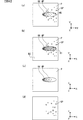
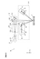
- FIG. 4 is a diagram schematically showing a molten pool generated by irradiating the material layer with laser light and a state in the vicinity thereof.
- FIG. 4A is a molten pool on the material layer in the XY plane and the vicinity thereof.
- FIG. 4B is a cross-sectional view in the ZX plane.
- the solidified region BE formed by solidification is shown.
- FIG. 4 shows a case where the scanning of the laser beam is performed from the X direction + side to the ⁇ side.
- the scanning interval (scanning pitch) is irradiation of two laser beams adjacent in a direction (Y direction in FIG. 4A) intersecting the scanning direction of laser light (X direction in FIG. 4A). It is the position interval.
- a layered solidified layer having a predetermined thickness is formed along the Z direction.
- the powder material P of the material layer is irradiated with laser light from the irradiation unit 32 to suppress the formation of a formation defect in the solidified layer and the formation of the formation defect is suppressed.
- control is performed so that the following basic conditions are maintained within a certain range.
- the power density PD [J / mm 2 ] which is the amount of heat flowing into the powder material P per unit area of the material layer by laser light irradiation, and the powder material per unit volume of the material layer by laser light irradiation Energy density ED [J / mm 2 ], which is the amount of heat flowing into P, and temperature distribution T (r) [° C.] of molten material MP melted by laser light irradiation and powder material P in the vicinity thereof
- the power density PD, energy density ED, and temperature distribution T (r) are expressed by the following equations (1) to (3), respectively.
- at least one of the above parameters is controlled by a policy opposite to the above policy so that the value of the power density PD in the equation (1) decreases. It is good to be done.
- the reverse policy is that at least one of the policies illustrated below is performed.
- the parameter ⁇ for example, a powder material P having a low absorption rate is used.
- the laser output is decreased or the amount of heat applied to the powder material P from the outside is decreased.
- the parameter d for example, to increase the spot size.
- For reduction and parameter v for example, increasing the scanning speed.
- Equation (2) indicates that at least one of the parameters only needs to be controlled based on the following policy in order to increase the value of the energy density ED and facilitate melting of the powder material P.
- the parameter ⁇ as in the case of the above equation (1), for example, the powder material P having a high laser light absorption rate is used.
- the parameters P L and P 0 for example, the laser output is increased or the amount of heat applied to the powder material P from an external heating device is increased.
- the parameter ⁇ for example, the density of the material layer is increased and the gap in the material layer is reduced.
- the heat generated by the laser light irradiation is easily conducted through the powder material P.
- the scanning speed is lowered and the time during which the powder material P contained per unit area of the material layer is irradiated with the laser light is increased.
- the amount of heat flowing into the powder material P is increased.
- the scanning pitch is narrowed.
- region BE becomes large.
- the parameter ⁇ z for example, the lamination thickness is reduced.
- the influence of the heat of the solidified layer already formed on the lower layer (Z direction-side) is increased, so that the initial temperature of the powder material P is increased. For this reason, the amount of heat required for the powder material P irradiated with the laser light to rise to a desired temperature (for example, melting point) is reduced.
- the spatter SP and the fume FU cause a modeling defect of the three-dimensional structure. Therefore, in order to suppress the generation of the spatter SP and the fume FU, the power density PD and the energy density ED are not excessively increased. It needs to be controlled.
- the powder material P cannot sufficiently receive the energy of the irradiated laser beam, and the powder material P may not be melted (unmelted). Melting defects such as the inability to obtain a molten pool MP of a large size occur, which causes a modeling defect of the three-dimensional structure. For this reason, it is necessary to control the power density PD and the energy density ED so as not to decrease excessively. As described above, the power density PD and the energy density ED do not become too large or too small and need to be maintained in a certain range. This certain range is calculated from the results of various tests and simulations by the user so that the three-dimensional structure becomes a good product. A certain range of the power density PD and energy density ED in which the three-dimensional structure is a good product is referred to as a desired range.
- the temperature distribution T (r) shown in the formula (3) is centered on the irradiation position of the laser beam on the material layer when the material layer irradiated with the laser beam is irradiated under the currently set modeling conditions.
- the state in which the temperature changes in the molten pool MP is controlled by setting the modeling conditions so that the temperature distribution T (r) is maintained in a certain range.
- the crystal structure in the solidified layer after solidification can be maintained in a desired structure, or the convection C of the molten pool MP can be controlled.
- the convection C of the molten pool MP due to the laser light irradiation affects the shape of the molten pool MP (that is, the shape of the solidified region BE after solidification and the penetration depth when melted in the Z direction-side). . Therefore, by maintaining the temperature distribution T (r) within a certain range, the state of the convection C of the molten pool MP, which is the behavior of heat due to the irradiation of the laser beam in the molten pool MP, is controlled. Thereby, generation
- the detection unit 54 obtains the state of the detection target region described above based on the image data from the imaging device 41.
- the state of the detection target region the state of the powder material P before being heated by the irradiation of the laser light, the melting state in the detection target region, the state of the sputter SP, and being heated by being irradiated with the laser light It includes at least one state with the state of the generated fume FU.
- the detection unit 54 is, for example, the temperature of at least a part of the molten pool MP and its vicinity (a semi-solid region or a solidified region BE in which the solution has become a solid phase after melting). Ask for information about.
- the detection unit 54 obtains, for example, at least one of the scattering direction, the scattering amount, and the scattering speed of the sputtering SP as the state of the sputtering SP.
- the detection unit 54 obtains, for example, at least one of the concentration and range of the fume FU as the state of the fume FU.
- the change of the modeling condition based on the state of the detection target region obtained by the detection unit 54 includes a real-time change, a change at the time of the next layer modeling, and a change at the time of the next modeling object modeling.
- the modeling conditions are changed when the solidified layer is modeled by irradiating the laser beam on the material layer used for obtaining the state of the detection target region or during modeling. Therefore, in real-time change, modeling conditions are changed with respect to the unmelted powder material P among the material layers during modeling of the solidified layer.
- the modeling conditions are changed when the formation of the material layer of the next layer or the modeling of the solidified layer is started from the material layer of the next layer after the modeling of the solidified layer. Therefore, in the change at the time of the next layer modeling, the modeling conditions are changed with respect to the new powder material P supplied on the solidified layer formed or the new powder material P supplied onto the solidified layer.
- the solidification layer is stacked, the modeling of the three-dimensional modeling object is finished, and the modeling condition is changed when the modeling of the next three-dimensional modeling object is started.
- FIG. 5 is a diagram schematically showing an example of a temperature image corresponding to the temperature image data generated by the detection unit 54 based on image data obtained by imaging the detection target region shown in FIG. The case where light is scanned on the material layer from the X direction + side to the-side is shown.
- the temperature difference in the molten pool MP of the temperature image is represented by using an isotherm indicated by a broken line, and a range affected by the fume FU is indicated by hatching. ing.
- the imaging device 41 images the detection target region including the molten pool MP in the material layer. Therefore, the generated temperature image data (temperature image) includes the molten pool MP, the solidified region BE that has been solidified, and the powder material P with the keyhole KH as the center of the image. Since the laser beam is scanned toward the X direction minus side, in the temperature image, the molten pool MP has a larger elliptical region on the X direction plus side than the X direction minus side with respect to the keyhole KH.
- the sputter SP when the granular spatter SP is scattered by the irradiation of the laser beam, the sputter SP also has heat, and is included in the temperature image data (temperature image). Further, when fume FU, which is an evaporant, is generated by irradiation with laser light, fume FU also has heat and is included in the temperature image data (temperature image).
- the detection unit 54 detects the state of the powder material P before heating by irradiation with laser light, the state of melting in the detection target region, The state and the state of the fume FU are obtained.
- the state of the detection target region detection of the state of the powder material P before heating by laser light irradiation, detection of the melting state in the detection target region, detection of the state of the sputter SP, and the state of the fume FU The description is divided into detection.
- the detection unit 54 when the detection unit 54 obtains the temperature of the powder material P in the material layer before heating by laser light irradiation, the temperature of the powder material P should be obtained in an area in the scanning direction with respect to the irradiation position of the laser light. It can be estimated as a region on the material layer.
- the detection part 54 calculates
- the detection unit 54 uses the temperature image data to obtain the temperature distribution, maximum temperature, minimum temperature, average temperature, etc. of the powder material P before heating as information on the temperature of the powder material P before heating by laser light irradiation. .
- the detection unit 54 can obtain the initial temperature T 0 is a parameter of the equation (3).
- the detection unit 54 may use the known image processing method from the image data captured by the imaging device 41 to obtain the foreign material or spatter SP contained in the powder material P as the state of the powder material P before heating. Good.
- the detection part 54 does not need to obtain
- an existing radiation thermometer is used instead of the imaging device 41, the two-branch optical system 42, the chromatic aberration correction optical system 43, and the field stop 302. You may acquire the temperature data based on infrared rays.
- the detection unit 54 may obtain the state of the powder material P before heating by laser light irradiation based on the temperature data acquired by the acquisition unit 310 (a radiation thermometer (not shown)).
- the acquisition unit 310 may not be a radiation thermometer, but an existing contact thermometer such as a thermocouple may be used.
- a plurality of thermocouples are installed at arbitrary positions in the modeling tank 31 and the material layer forming unit 20 of the modeling unit 30, and temperature data at each position is acquired by the plurality of thermocouples.
- the detection part 54 utilizes the data regarding the correlation between the temperature data acquired with the thermocouple and the temperature data of the powder material P before heating by laser beam irradiation, and the powder before heating by laser beam irradiation The state of the material P may be obtained.
- Data relating to the correlation between the temperature data acquired by the thermocouple and the temperature data of the powder material P before being heated by the laser light irradiation is stored in the storage unit 58 in advance.
- the detection unit 54 obtains information on the temperature of the molten pool MP and its vicinity (the solidified region BE in the detection target region) as a molten state from the temperature image data. In this case, the detection part 54 calculates
- the detecting unit 54 obtains a region lower than the first predetermined temperature among the estimated regions as the temperature of the solidified region BE after heating by laser light irradiation.
- the detection unit 54 melts the region (semi-solidified region) in which the liquid phase molten pool MP has started to solidify into a solid phase (semi-solidified region) in the region of the temperature image data that is equal to or higher than the first predetermined temperature.
- the temperature in this region may be obtained by estimation from the pond MP.
- Information related to at least a part of the temperature of the molten pool MP and its vicinity obtained by the detection unit 54 includes the temperature distribution of the molten pool MP, the highest temperature, the lowest temperature, the average temperature, the position of the keyhole KH, the uppermost surface ( The diameter of the keyhole KH (for example, the length of the short axis), the size of the molten pool MP, the thermal conductivity, the temperature gradient on the surface of the molten pool MP, the boundary of the molten pool MP on the surface It includes solidification rate, temperature history, etc., which are changes in temperature.
- the detection unit 54 includes, as information related to temperature, the temperature distribution of the solidified region BE and the semi-solidified region, the maximum temperature, the minimum temperature, the average temperature, the size, the thermal conductivity, the temperature gradient, the solidification rate, and the temperature. Get history etc.
- the detecting unit 54 obtains the temperature at a plurality of positions in the region estimated as the molten pool MP in the temperature image data, for example, and obtains the temperature distribution of the molten pool MP by setting isotherms for each predetermined temperature.
- the detection unit 54 obtains the highest temperature as the highest temperature and obtains the lowest temperature as the lowest temperature in the region estimated as the molten pool MP in the temperature image data.
- the detection part 54 calculates
- the detection unit 54 obtains the center of the temperature image data as the position of the keyhole KH.
- the detection unit 54 obtains a range that can be regarded as substantially the same temperature as the temperature at the center of the temperature image data as the opening of the keyhole KH on the uppermost surface, and obtains the length of the short axis of the obtained opening as the opening diameter.
- the detection part 54 calculates
- the detection unit 54 calculates a temperature gradient on the surface of the molten pool MP and a solidification rate that is a change in the temperature of the boundary portion of the molten pool MP on the surface. Ask. Using a plurality of temperature image data generated by imaging at predetermined intervals, the detection unit 54 obtains a temperature history in the molten pool MP and its vicinity. The temperature history is data representing a temperature change at a certain position of the material layer. An example of temperature history detection will be described below.
- the image data generated by the imaging device 41, the irradiation position information indicating the irradiation position of the laser beam (that is, the position of the keyhole KH), and the time information are stored in association with each other.
- the detection unit 54 obtains a temperature history based on the irradiation position information associated with the image data.
- a certain temperature image first temperature image
- the detection unit 54 obtains the temperature at the position Q1 from the first temperature image data.
- the detection unit 54 obtains the position of the position Q1 on the second temperature image different from the first temperature image.
- the detection unit 54 determines the first temperature based on the irradiation position of the laser beam when the first image data is generated and the irradiation position of the laser beam when the second image data is generated.
- the position on the material layer of the keyhole KH1 which is the center in the image and the position on the material layer of the keyhole KH2 which is the center in the second temperature image are obtained.
- the center of the second temperature image is equal to the value obtained by converting the difference n between the keyholes KH1 and KH2 on the material layer into the distance on the temperature image.
- the position shifted from the X direction to the + direction becomes the position Q2 on the second temperature image (the keyhole KH in the first temperature image).
- the detecting unit 54 obtains a position further away from the position Q2 on the second temperature image by the distance m in the X direction + side as the position Q1, and obtains the temperature at this position from the second temperature image data. Thereafter, the detection unit 54 can obtain the temperature history at the position Q1 by similarly obtaining the temperature at the position Q1 from a plurality of temperature image data.
- the detecting unit 54 obtains information on the temperature of the solidified region BE as a state in the vicinity of the molten pool MP from the temperature image data. In this case, the detection unit 54 obtains the temperature distribution and average temperature of the solidified region BE. In addition, the detection part 54 may obtain
- the detection part 54 does not need to obtain
- the acquisition unit 310 uses an existing radiation thermometer instead of the imaging device 41, the bifurcated optical system 42, the chromatic aberration correction optical system 43, and the field stop 302, and temperature data based on infrared rays from the molten pool MP and its vicinity. May be obtained.
- the detection unit 54 may obtain the melting state based on temperature data acquired by the acquisition unit 310 (a radiation thermometer (not shown)).
- the acquisition unit 310 may not be a radiation thermometer, but an existing contact thermometer such as a thermocouple may be used.
- a plurality of thermocouples are installed at arbitrary positions in the modeling tank 31 and the material layer forming unit 20 of the modeling unit 30, and temperature data at each position is acquired by the plurality of thermocouples.
- the detection part 54 utilizes the data regarding the correlation with the temperature data acquired with the thermocouple, and the temperature data of the molten pool MP and its vicinity (solidification area
- Data relating to the correlation between the temperature data acquired by the thermocouple and the temperature data of the molten pool MP and its vicinity (solidified region BE in the detection target region) is stored in the storage unit 58 in advance.
- the detection unit 54 obtains at least one of the spatter amount, the scattering direction, and the scattering speed of the spatter SP as the state of the spatter SP. As described above, since the state of the spatter SP is related to the convection C in the molten pool MP, the detection unit 54 indirectly determines the state of the convection C inside the molten pool MP by obtaining the state of the sputter SP. Can be requested.
- FIG. 6 shows a temperature image excluding the fume FU and the solidified region BE from FIG. 5 as a temperature image corresponding to the temperature image data used for obtaining the state of the sputter SP for convenience of explanation.
- the detection unit 54 sets a region of interest used for obtaining the state of the sputter SP in the temperature image data.
- the detection unit 54 sets, as the region of interest, a region excluding the region occupied by the keyhole KH and the molten pool MP in the temperature image shown in FIG.
- the detection unit 54 can estimate a region (exclusion target region) including the keyhole KH and the molten pool MP from the equation (3) representing the temperature distribution T (r) described above.
- the expression (3) representing the temperature distribution T (r) represents the temperature of the powder material P at an arbitrary distance r from the laser light irradiation position (that is, the position of the keyhole KH), and the output of the laser light.
- the modeling conditions for modeling a three-dimensional model such as are used as parameters.
- the detection unit 54 is equal to or higher than the first predetermined temperature including the position of the keyhole KH (that is, the center of the temperature image) based on the expression (3) representing the temperature distribution T (r) and the set modeling conditions.
- the high temperature region is obtained, and the obtained high temperature region is obtained as an exclusion target region.
- the detection unit 54 calculates the parameter r by inputting the value of the first predetermined temperature and the value of each parameter determined by the currently set modeling conditions to the temperature distribution T (r) in the equation (3).
- FIG. 6B shows the exclusion target region R1 (indicated by hatching in FIG. 6B) obtained by the detection unit 54 with respect to the temperature image shown in FIG. It is a figure which shows typically the region of interest R2 set based on the object region R1, and the region of interest R2 is a region where the melting of the powder material P due to laser light irradiation has not occurred. For this reason, when the high temperature region exists in the region of interest R2, the detection unit 54 obtains the high temperature region as the sputter SP. The detection unit 54 obtains the amount of spattering SP by counting the number of high temperature regions included in the region of interest R2.
- the detection unit 54 can determine the scattering direction of the sputter SP on the XY plane by determining the orientation from the center of the temperature image, that is, the irradiation position of the laser light, to each high temperature region included in the region of interest R2. .
- the detection part 54 calculates
- the detection unit 54 detects the size and temperature in one temperature image data (temperature image) of the sputter SP remaining as a detection target (that is, the sputter SP displaced with time), and the other temperature image data ( Sputter SPs that can be regarded as having the same size and temperature in (temperature image) are obtained as spatter SPs (the same spatter) being scattered.
- the detection unit 54 obtains the position (first position) in the upper space of the material layer from one temperature image data (temperature image) for the sputter SP obtained as the same sputter, and the other temperature image data (temperature image). ) To obtain the position (second position) in the upper space of the material layer.
- the detection unit 54 calculates (detects) the scattering speed of the sputter SP (the same spatter that has been scattered) from the first position, the second position, and the time information difference between the two temperature image data.
- the detection unit 54 may obtain the state of the spatter SP without setting the region of interest R2 in the temperature image data (temperature image).
- the detection unit 54 adds a plurality of temperature image data generated from the image data output by the imaging device 41 and takes the average to generate average temperature image data.
- the plurality of temperature image data may be temperature image data generated from image data associated with different time information. Further, the plurality of temperature image data may be temperature image data generated in advance and stored in the storage unit 58 at different times or different positions.
- the detection unit 54 may generate average temperature image data every time temperature image data is generated, or may generate average temperature image data every time a predetermined number of temperature image data are generated.
- the generation state of spatter SP (the number, position, size, etc.
- the average temperature image data (average temperature image) generated based on the plurality of temperature image data the position where the sputter SP is detected in a certain temperature image data (temperature image) is the other many temperature image data.
- the spatter SP is removed by adding and averaging the position where the spatter SP in the (temperature image) is not detected.
- the average temperature image data (average temperature image) from which the spatter SP has been removed includes the keyhole KH and the molten pool MP.
- FIG. 6C schematically shows an example of the average temperature image corresponding to the average temperature image data generated by the above processing.
- the average temperature image has no high temperature region other than the keyhole KH and the molten pool MP.
- the detection unit 54 calculates the average corresponding to the average temperature image shown in FIG. 6C from the temperature image data (detection target image data) corresponding to the temperature image for detecting the sputter SP shown in FIG. Take the difference from the temperature image data.
- FIG.6 (d) the image from which the keyhole KH and the molten pool MP were removed from a detection target image is produced
- the detection unit 54 determines the amount of spatter SP scattered based on the high-temperature region as described above in the same manner as described with reference to FIG. Then, at least one of the scattering direction and the scattering speed is obtained. In particular, the detection unit 54 can obtain the spatter SP and the scattering direction scattered in the X direction + side (backward with respect to the laser beam scanning direction) with respect to the center of the temperature image.
- the detection part 54 does not need to obtain
- the acquisition unit 310 may use an imaging device (not shown) instead of the imaging device 41, the two-branch optical system 42, the chromatic aberration correction optical system 43, and the field stop 302 to acquire image data of the detection target region.
- the imaging device (not shown) may have the same configuration as the imaging device 41 in FIG. 1 or may have another existing configuration.
- the detection unit 54 performs existing image processing using the image data acquired by the acquisition unit 310 (an imaging device (not shown)), and forms a circular image having a predetermined size from the image as a sputter image. To detect. Then, the detection unit 54 obtains at least one of the scattering amount, the scattering direction, and the scattering speed of the spatter SP from the time change and the number of the positions of the detected sputter images.
- the detection unit 54 obtains at least one of the concentration and the range of the fume FU as the state of the fume FU from the temperature image data. As described above, since the state of the fume FU is related to the convection C in the molten pool MP, the detection unit 54 indirectly determines the state of the convection C inside the molten pool MP by obtaining the state of the fume FU. Can be requested.
- FIG. 7 shows an example of a temperature image corresponding to the temperature image data used for obtaining the state of the fume FU.
- the solidified region BE is omitted for convenience of illustration.
- the fume FU is generated from the molten pool MP generated by being irradiated with the laser light, the luminance of the light from the detection target region of the material layer is lowered due to the influence of the fume FU.
- the hatched area represents an area where the luminance value is lowered due to the influence of the fume FU.
- FIG. 7A is the same temperature image as the temperature image shown in FIG. FIG.
- FIG. 7 shows original image data of temperature image data corresponding to this temperature image, that is, images corresponding to respective image data generated when light of wavelength ⁇ 1 and light of wavelength ⁇ 2 are incident on different positions of the image sensor 411. This is schematically shown in (b).
- an image D1 with light of wavelength ⁇ 1 is shown on the left side of the paper
- an image D2 with light of wavelength ⁇ 2 is shown on the right side of the paper.
- the luminance value of the radiated light from the detection target region of the material layer is affected by the fume FU
- the luminance value of both the image D1 and the image D2 is decreased.
- the image D1 is brighter (higher brightness) than the image D2.
- the brightness is lowered in the region R3 and the region R4 affected by the fume FU in both the bright image D1 and the dark image D2.
- the reduction rate of the brightness of the bright image D1 and the dark image D2 is substantially equal.
- the detection unit 54 performs the separation of the molten pool MP, the keyhole KH, the spatter SP, and the fume FU based on whether or not the luminance value ratio changes between the image D1 and the image D2. Since the fume FU blocks the light from the molten pool MP, the luminance values of both the light with the wavelength ⁇ 1 and the light with the wavelength ⁇ 2 are reduced, but the ratio of the luminance values does not change between the image D1 and the image D2. On the other hand, the ratio of the luminance values changes in the molten pool MP, the keyhole KH, and the spatter SP.
- the detection unit 54 Since the luminance information of each pixel of the image D1 and the image D2 is known, the detection unit 54 detects the molten pool MP, the keyhole KH, the sputter SP, and the fume FU based on whether or not the ratio of the luminance values is changed. Can be carved. The detection unit 54 obtains the fume FU (the region R3 of the image D1 and the region R4 of the image D2) thus cut out as the range of the fume FU.
- the detection unit 54 detects the luminance value of the image D1 or the image D2 in the image data acquired when the image data corresponding to the original image illustrated in FIG. 7B is acquired, and FIG. The difference may be calculated by comparing the brightness value of the image D1 or the image D2 in the image data of the original image of b).
- the luminance value of both the image D1 and the image D2 is reduced due to the effect of the fume FU, and thus the image D1 and the image D2 are generated based on the ratio between the luminance information of the light with the wavelength ⁇ 1 and the luminance information of the light with the wavelength ⁇ 2.
- the temperature image is not affected by the thermal radiation light being blocked by the fume FU.
- the detection unit 54 may obtain the state of the fume FU using the average temperature image data.
- the average temperature image data is generated in the same manner as the generation method described in the process for obtaining the state of the sputter SP.
- the generation state of fume FU (the density and range of fume FU on the temperature image data) is different for each temperature image data. For this reason, even if a fume FU is detected in a certain temperature image at the same position on a plurality of temperature images, the fume FU is not necessarily detected in many other temperature images.
- the position affected by the fume FU in a certain temperature image data is affected by the fume FU in many other temperature image data.
- the influence of the fume FU is removed by adding and averaging with the positions that are not.
- the average temperature image data from which the fume FU has been removed includes the keyhole KH and the molten pool MP.
- the detection unit 54 generates average temperature image data corresponding to the same average temperature image as that shown in FIG.
- the detection unit 54 obtains the diffusion state of the fume FU, that is, the range of the fume FU. Since the fume FU also has a heat quantity, the detection unit 54 obtains the temperature in the range of the detected fume FU from the image data corresponding to the image shown in FIG. It can be considered that the higher the temperature, the more fume FU is generated, that is, the concentration of the fume FU is high. Therefore, the detection unit 54 obtains the concentration of the fume FU based on the obtained temperature within the range of the fume FU.
- the detection unit 54 separates the molten pool MP, the keyhole KH, the sputter SP, and the fume FU using the method described in the process for obtaining the state of the fume FU, and detects the fume FU as temperature image data (temperature image). ).
- the detection part 54 should just obtain
- the detection unit 54 separates the fumes FU and the spatter SP based on the difference in area from the image data corresponding to the image shown in FIG. 7C generated based on the average temperature image data. You may obtain
- the detection part 54 does not need to obtain
- an illumination device and an imaging device may be used instead of the imaging device 41, the bifurcated optical system 42, the chromatic aberration correction optical system 43, and the field stop 302.
- the illumination device is disposed on the X direction + side and the imaging device is disposed on the X direction ⁇ side with respect to the center of the base plate 311 in FIG.
- the illumination device and the imaging device are arranged to face each other so that illumination light from the illumination device is received by the imaging device.
- the illuminating device (not shown) is an existing surface emitting LED
- the imaging device (not shown) has the same configuration as the imaging device 41 of FIG.
- the detection unit 54 can obtain the range in which fume is generated by comparing the signal intensity of each pixel in the image data generated by the imaging apparatus with a predetermined threshold. Further, the higher the concentration of the fume FU, the greater the influence of scattering by the fume FU, and the intensity of illumination light from the illumination device is greatly attenuated. Therefore, the detection unit 54 can obtain the density (density distribution) of the fume FU based on the signal intensity of each pixel in the image data generated by the imaging apparatus.
- the acquisition unit 310 a pair of an illumination device (not shown) and an imaging device are arranged in different directions (for example, the illumination device is arranged on each of the X direction + side and the Y direction + side with respect to the center of the base plate 311.
- the detection unit 54 generates the fume FU based on the signal intensity of each pixel in the image data generated by each imaging device.
- a spatial range and a spatial density (density distribution) may be obtained.
- the illumination device does not have to be a surface-emitting LED, and any other existing configuration may be used as long as it can emit light in a space where a fume FU may be generated. In addition, surface light emission may not be performed, and an existing point light emission type illumination device may be used.
- the correlation between the state of fume FU (spatter SP range and concentration) and the convection C of the molten pool MP, and the correlation between the convection C of the molten pool MP and the molten state (temperature information) of the molten pool MP can be understood.
- the detection unit 54 may determine the melting state of the molten pool MP (indirectly) based on the determined state of the fume FU.
- data relating to the correlation between the state of the fume FU and the state of melting of the molten pool MP is stored in the storage unit 58 in advance.
- the calculating part 56 produces
- the following (2-1) to (2-7) are exemplified as the modeling conditions to be changed.
- FIG. 8 and FIG. 9 show the main modeling conditions, the basic conditions of power density PD, energy density ED and temperature distribution T (r), and parameters shown in equations (1) to (3). The relationship is shown.
- FIGS. 8 and 9 indicate basic conditions that can be controlled by each modeling condition by ⁇ , and blank basic conditions that cannot be controlled or have little effect even if controlled.
- FIG. 8 and FIG. 9 show parameters of the expressions (1) to (3) related to each modeling condition.
- FIG. 8 and FIG. 9 show at which timing each modeling condition can be changed, that is, the above-described real-time change, change at the next layer modeling, and change at the next modeling object modeling.
- the laser output affects the amount of heat given to the powder material P irradiated by the laser light emitted from the laser oscillator 321, and the amount of heat absorbed by the powder material P increases as the laser output increases.
- the laser output is shaped condition change information related to the parameter P L as described above is generated. As described above, when the laser output is increased, the values of the power density PD, energy density ED, and temperature distribution T (r) increase.
- the change information for changing the laser output is a new output value of the laser beam emitted from the irradiation unit 32 or a correction value to the currently set output value of the laser beam.
- the wavelength of the laser beam is related to the absorption rate at which the powder material P absorbs the laser beam.
- the wavelength of the laser light is a modeling condition in which change information is generated in relation to the parameter ⁇ , and the value of the parameter ⁇ decreases as the wavelength of the laser light increases. For this reason, the wavelength of the laser beam affects the values of the power density PD and the energy density ED.
- the change information for changing the wavelength of the laser light is, for example, information indicating which of the wavelengths that can be emitted as the laser light is emitted.
- the laser light with the Gaussian distribution and the laser light with the top hat distribution can be switched as described above.
- the intensity distribution of the laser light of Gaussian distribution is strongest near the central axis of the laser light beam and gradually weakens toward the periphery.
- the intensity distribution of the laser light having the top hat distribution is uniform in the peripheral portion away from the vicinity of the central axis of the light beam of the laser light as compared with the laser light having the Gaussian distribution.
- a laser beam having an intensity necessary for melting the powder material P is irradiated over a wider range than the laser light having a Gaussian distribution.
- the intensity distribution of the laser beam affects the spot size of the laser beam on the upper surface of the material layer. That is, the laser light intensity distribution is a modeling condition in which change information is generated in relation to the parameter d.
- the intensity distribution of the laser light is switched to the top hat distribution, the spot size is increased, and the amount of heat flowing into the powder material P per unit area on the material layer is reduced by irradiation with the laser light.
- the intensity distribution is a top hat distribution, the value of the parameter d increases, and the values of the power density PD and energy density ED decrease.
- the intensity distribution near the central axis of the light beam of the laser light is the strongest.
- a narrow area on the layer is irradiated.
- the spot size is reduced, and the amount of heat flowing into the powder material P per unit area on the material layer due to the laser light irradiation increases.
- the change information for changing the intensity distribution of the laser light is, for example, information indicating which intensity distribution of the Gaussian distribution or the top hat distribution is used to emit the laser light.
- the intensity distribution of the laser beam is affected by the laser quality [M 2 ].
- the intensity distribution of the laser light is a single-mode Gaussian distribution, and as M 2 changes from 1 (M 2 is a value of 1 or more), the intensity distribution of the laser light is derived from the single-mode Gaussian distribution. Change. Therefore, the value of the parameter d changes according to the laser quality.
- the spot size of the laser beam affects the range on the XY plane of the material layer irradiated by the laser beam. As the spot size of the laser beam that irradiates the upper surface of the material layer is smaller, the amount of heat per unit area on the material layer increases, and the amount of heat that flows into the powder material P per unit area on the material layer increases due to irradiation of the laser beam. As a result, melting of the powder material P irradiated with the laser light is promoted, and the convection C in the molten pool MP is affected. For this reason, the spot size of the laser beam is a modeling condition in which change information is generated in relation to the parameter d.
- Conditions related to the scanning unit 33 As specific examples of the modeling conditions with respect to the scanning conditions for scanning the material layer with the laser light, the scanning speed of the laser light [mm / s] and the scanning of the laser light There is at least one condition of an interval (scanning pitch) [mm] between irradiation positions of two laser beams adjacent in a direction crossing the direction and a scanning path of the laser beam.
- the scanning speed of the laser beam is related to the time for which the laser beam is irradiated per unit area of the surface of the material layer. There is an influence on the temperature change (temperature gradient) in the molten pool MP accompanying the movement of the position irradiated with light.
- the scanning speed of the laser beam is high, the amount of heat flowing into the powder material P contained per unit area of the surface of the material layer by irradiation with the laser beam is reduced.
- the scanning speed of the laser beam is low, the amount of heat flowing into the powder material P included per unit area of the surface of the material layer is increased by the irradiation of the laser beam.
- the scanning speed of the laser beam is a modeling condition for generating change information in relation to the parameter v. As the scanning speed increases, the parameter v increases, and the values of power density PD, energy density ED, and temperature distribution T (r) decrease.
- the change information for changing the scanning speed is, for example, a new change speed of the tilt angle of the galvanometer mirrors 331 and 332 or a correction value of the change speed of the currently set tilt angle.
- the scanning pitch When the scanning pitch is small, the influence of heat from the adjacent solidified region BE already formed by the laser beam irradiation is large. Therefore, the initial temperature of the powder material P that has not been irradiated with the laser light is increased, and the amount of heat necessary for the increase to a desired temperature (for example, the melting point) is reduced. That is, the smaller the scanning pitch, the greater the heat absorption rate of the powder material P, and the larger the scanning pitch, the smaller the heat absorption rate of the powder material P. If the scanning pitch is small, heat from a direction different from the scanning direction of the laser beam affects the convection C in the molten pool MP.
- the scanning pitch is a modeling condition in which change information is generated in relation to the parameters ⁇ and ⁇ y.
- the scanning pitch affects the values of power density PD and temperature distribution T (r).
- the change information for changing the scanning pitch is, for example, a new set angle to be changed from the current set angle of the galvano mirrors 331 and 332, or a correction value to be changed from the current set angle to the new set angle. .
- the scanning path of the laser beam is a modeling condition related to a path setting method for irradiating the surface of the material layer with the laser beam.
- a scanning path for example, after irradiating laser light along the contour of a shape (modeling model) based on slice model data, the inside of the contour is irradiated with laser light, or inside the shape (modeling model) contour based on slice model data
- the laser beam is irradiated along the contour of the shape (modeling model) based on the slice model data.
- the scanning path of the laser light is a path that makes it difficult for residual stress to be generated in the solidified layer formed by the laser light, for example, based on the initial temperature T 0 of the material layer before the laser light is irradiated. To be determined.
- the flow rate of the inert gas introduced into the housing 10 [mm 3 / s], a flow rate [mm / s] of the inert gas introduced into the housing 10, and a temperature [° C.] in the housing 10.
- the flow rate and flow rate of the inert gas affect the initial temperature of the material layer before the laser light irradiation and the fumes FU generated from the powder material P by the laser light irradiation.
- the surface of the material layer is cooled by the inert gas, so that the temperature of the powder material P irradiated to the laser light is a desired temperature (for example, a melting point). )
- the amount of heat required to rise is increased. Therefore, flow rate and flow velocity of the inert gas, so affects the initial temperature before the powder material P is subjected to irradiation of the laser beam, a shaped condition associated with the parameter P 0.
- the flow rate of the inert gas when the flow rate of the inert gas is low or the flow velocity is low, the fumes FU generated by the laser light irradiation stay in the vicinity of the laser light irradiation position and block the optical path of the laser light toward the material layer. . For this reason, the amount of heat flowing into the powder material P is reduced by the irradiation of the laser beam, and there is a possibility that the molten state is different from the assumed molten state. Therefore, the flow rate and flow velocity of the inert gas are the modeling conditions related to the parameter ⁇ because the powder material P affects the absorption rate when the heat generated by the laser light irradiation is absorbed.
- the flow rate and flow rate of the inert gas are modeling conditions in which change information is generated in relation to the parameters P 0 and ⁇ . For example, when the flow rate of the inert gas increases and the flow rate increases, the value of the parameter P 0 Decreases, the parameter ⁇ increases, and the temperature distribution T (r) decreases.
- the flow rate and flow rate of the inert gas affect the values of the power density PD and energy density ED.
- the change information for changing the flow rate and flow rate of the inert gas includes, for example, a new valve opening of the valve that is the intake device 131, a new exhaust amount of the exhaust device 14, or a currently set valve opening. And the displacement correction value.
- Temperature in the housing 10 affects the initial temperature before the material layer is irradiated with a laser beam, a shaped condition which changes in relation to P 0 parameter information is generated. Since the powder material P is warmed and the initial temperature becomes higher as the temperature in the housing 10 is higher, the amount of heat required until the temperature of the powder material P rises to a desired temperature (for example, melting point) by irradiation with laser light is small. Become. Therefore, the temperature in the casing 10 affects the initial temperature before the powder material P is irradiated with the laser beam, and is therefore a modeling condition related to the parameter P 0.
- a desired temperature for example, melting point
- the temperature in the casing 10 is As the value increases, the value of the parameter P 0 increases, and the values of the power density PD, energy density ED, and temperature distribution T (r) increase.
- the change information for changing the temperature in the housing 10 is, for example, a new heating output value of the heater 15 or a currently set correction value of the heating output of the heater 15.
- (2-4) Material Layer Formation Conditions for Forming the Material Layer As specific examples of the modeling conditions for forming the material layer, the moving speed [mm / s] of the blade 221 and the blade 221 added to the powder material P The pressure [Pa], the time [s] that the blade 221 waits until the formation of a new material layer on the solidified layer after the solidified layer is formed, the shape of the blade 221, the material of the blade 221, There is at least one condition of the stacking thickness [mm] of the material layer on the base plate 311.
- the moving speed of the blade 221 and the pressure applied to the powder material P by the blade 221 affect the flatness of the surface of the material layer to be formed and the thickness and density of the material layer. For example, when the moving speed of the blade 221 is high, the flatness of the surface of the material layer is decreased, the stacking thickness is increased, and the density is decreased as compared with the case where the moving speed of the blade 221 is low. Further, when the pressure applied to the powder material P by the blade 221 is high, the flatness of the surface of the material layer is increased, the lamination thickness is decreased, and the density is increased as compared with the case where the pressure is low.
- the change information for changing the moving speed of the blade 221 is a new value of the motor output constituting the drive mechanism for moving the blade 221 or a correction value of the currently set motor output.
- the change information for changing the pressure applied to the powder material P by the blade 221 may be, for example, a new driving amount value of the pressing mechanism or a correction value of the currently set driving amount of the pressing mechanism.
- the waiting time of the blade 221 is that the blade 221 transfers the powder material P from the material supply tank 21 to the modeling tank 31 after the irradiation of the laser beam to the material layer is completed for modeling the solidified layer. This is the time until transfer starts.
- the waiting time of the blade 221 affects the initial temperature of the material layer newly formed on the solidified layer. In other words, the longer the waiting time, the lower the temperature of the solidified layer that has been raised by the laser light irradiation, so that the initial temperature of the material layer newly formed on the solidified layer is less likely to rise. In this case, the amount of heat necessary for the temperature of the powder material P irradiated with the laser light to rise to a desired temperature (for example, melting point) increases.
- a desired temperature for example, melting point
- the waiting time of the blade 221 is shaped condition change related to the parameter P 0 information is generated.
- the value of the parameter P 0 decreases, and the values of the power density PD, energy density ED, and temperature distribution T (r) decrease.
- the change information for changing the standby time of the blade 221 includes, for example, a value indicating the drive start timing of the motor that configures the drive mechanism that moves the blade 221 and correction of the currently set drive start timing of the motor. Value.
- the thickness of the material layer is not constant depending on the shape of the defect, the flatness is lowered, the laminated thickness is different from the desired thickness, The density may not be uniform or the surface roughness may increase. Even if the blade 221 has no defect, if the shape of the blade 221 changes, the contact area of the blade 221 with respect to the powder material P changes, so the density of the material layer, flatness, The stack thickness changes.
- the shape and material of the blade 221 can be changed by changing the type of the blade 221.
- the change information for changing the shape and material of the blade 221 is information indicating replacement of the blade 221, for example.
- the modeling apparatus 1 performs notification that prompts replacement of the blade 221.
- the modeling apparatus 1 may display a message indicating that it is necessary to change the type of the inert gas on a monitor (not shown) or emit a sound from a speaker (not shown).
- the type of the blade 211 is automatically replaced according to the control from the material control unit 51.
- the shape of the blade 221 is variable, the shape of the blade 221 can be changed according to control from the material control unit 51.
- the change information generated in this case is information that instructs to change the shape of the blade 221, for example.
- the stack thickness is a modeling condition in which change information is generated in relation to the parameter ⁇ z. For example, when the stack thickness increases, the value of the parameter ⁇ z increases and the value of the energy density ED decreases.
- the change information for changing the stacking thickness may be, for example, a new pressure value applied to the powder material P by the blade 221 of the recoater 22 or a correction value of the current pressure, or a new pressing mechanism for the blade 221.
- a correct driving amount value or a correction value of the driving amount of the pressing mechanism that is currently set may be used.
- the shape and material of the blade 221 can be changed by changing the next modeled object.
- the moving speed of the blade 221, the pressure applied to the powder material P, the waiting time, and the layer thickness of the material layer can be changed when the next layer is formed or when the next formed object is formed.
- the change information for changing the temperature of the base plate 311 is, for example, a new heating output value of the heater 313 or a currently set correction value of the heating output of the heater 313.
- the temperature of the base plate 311 If the temperature of the base plate 311 is high, the amount of decrease in temperature when the temperature of the solidified layer that has risen due to the irradiation of the laser beam decreases is small, so the effect of residual stress generated when the molten pool MP solidifies is small. Become. In addition, as described above, if the temperature of the base plate 311 is high, the amount of heat required for the temperature of the powder material P irradiated to the laser light to rise to a desired temperature can be reduced, so the output of the laser light is changed. Without increasing the scanning speed, the scanning speed can be increased. The temperature of the base plate 311 can be changed when changing at the time of forming the next layer or changing at the time of forming the next object.
- Design data related to the shape of the solidified layer or the three-dimensional structure As a specific example when the design data related to the shape of the solidified layer or the three-dimensional structure is used as a modeling condition, There is at least one data of slice model data that is shape data and shape data of a support portion that supports a solidified layer or a three-dimensional structure.
- the slice model data is shape data for determining the shape of the solidified layer to be shaped on the XY plane, the thickness of the solidified layer (slice pitch), and the like.
- the slice model data is a modeling condition in which change information is generated in relation to the parameter ⁇ z. That is, as the thickness of the solidified layer increases, the value of the parameter ⁇ z increases.
- various modeling conditions for the laser light from the irradiation unit 32 and various modeling conditions for scanning by the scanning unit 33 may be changed.
- the model data affects the values of power density PD, energy density ED, and temperature distribution T (r).
- the change information for changing the slice model data is, for example, a new shape of the solidified layer in the XY plane, a new thickness of the solidified layer, a correction value of the shape of the solidified layer in the XY plane, or a correction value of the thickness of the solidified layer. It is.
- the shape data of the support portion indicates the shape such as the thickness and length of the support portion that supports the three-dimensional structure in order to prevent deformation and breakage of the solidified layer and the three-dimensional structure.
- the shape of the support part is determined by the shape and size of the solidified layer or three-dimensional structure to be supported. The larger the volume of the support portion, the greater the influence of the heat of the portion of the solidified layer formed by laser light irradiation as the support portion on the material layer (powder material P) formed on the solidified layer. .
- the shape data of the support portion is a modeling condition that affects the parameter P 0 depending on the volume of the support portion and the temperature of the base plate 311, and affects the values of the energy density ED and the temperature distribution T (r).
- the change information for changing the shape data of the support part is, for example, a value of a new shape of the support part (such as length or thickness) or a correction value of the current shape of the support part (such as length or thickness). is there.
- the slice model data and the shape data of the support member can be corrected at the time of change at the time of the next modeled object modeling.
- Conditions related to the powder material P As specific examples of the molding conditions related to the powder material P, the particle size / particle size distribution of the powder material P, the moisture absorption of the powder material P, and the type of the powder material P There is at least one condition. Variations in the particle size and particle size distribution of the powder material P in the material layer may affect the thermal diffusivity and thermal conductivity of the material layer irradiated with the laser beam, and may cause defective melting. In addition, when the powder material P having a variation in particle size and particle size distribution is transferred to the modeling tank 31 by the blade 221, there may be a variation in thickness and density in the material layer. As a result, the solidified layer to be modeled May cause defects such as voids.
- the particle size / particle size distribution is a modeling condition in which change information is generated in relation to the parameters ⁇ z, ⁇ , k, ⁇ . For example, when the particle size / particle size distribution becomes large (the variation becomes large), the value of the parameter ⁇ z becomes large, the values of the parameters ⁇ , k, ⁇ become small, and the energy density ED and the temperature distribution T (r) The value increases.
- the change information for changing the particle size / particle size distribution of the powder material P is information for instructing to remove the formed material layer and form a new material layer, for example.
- the powder material P having high moisture absorption has low fluidity, and is difficult to be smoothly transferred to the modeling tank 31 by the blade 221. For this reason, the flatness and lamination thickness of the formed material layer are difficult to be uniform, and the surface roughness tends to increase. That is, the hygroscopicity of the powder material P is a modeling condition that affects the parameter ⁇ z. Also, if the moisture absorption of the powder material P is high, the flatness, lamination thickness, and density of the material layer are difficult to be uniform, so the temperature rise due to laser light irradiation is not uniform, and the solidified layer that is shaped by poor melting Defects such as voids may occur.
- the moisture absorption of the powder material P is a modeling condition in which change information is generated in relation to the parameters k and ⁇ . For example, when the moisture absorption of the powder material P is high, the values of the parameters k and ⁇ are decreased, and the value of the temperature distribution T (r) is decreased. Further, the moisture absorption of the powder material P affects the values of the power density PD and the energy density ED.
- the change information for changing the moisture absorption includes, for example, information indicating that the powder material P needs to be heated by the heater 213 and the heating output value of the heater 213.
- the types of powder material P include powder material P having different powder materials and additives.
- the type of the powder material P is different, the size of the powder, the thermal conductivity, the thermal diffusivity and the like are different. For example, even when the same pressure is applied to the powder material P having different particle diameters by the blade 221 when forming the material layer, when the powder material P having a large particle diameter is used, the particle diameter is small. Since the gap between particles in the material layer becomes larger than when the powder material P is used, the thickness of the material layer increases or the density decreases. For this reason, the type of the powder material P is a modeling condition that affects the parameters ⁇ z, ⁇ , k, ⁇ , and affects the energy density ED and the temperature distribution T (r).
- the change information for changing the type of the powder material P is, for example, information indicating that a different type of powder material P is used.
- the modeling apparatus 1 performs a notification that prompts the user to replace the powder material P, for example.
- the modeling apparatus 1 may display a message indicating that the type of the powder material P needs to be changed on a monitor (not shown), or emit a sound from a speaker (not shown).
- the material supply tank 21 is controlled according to control from the material control unit 51. Is exchanged, the type of the powder material P is automatically exchanged.
- the particle size / particle size distribution and type of the powder material P can be changed at the time of changing at the time of the next modeling object shaping.
- the moisture absorption of the powder material P can be corrected when the next layer is modeled or the next modeled object is modeled.
- each of the modeling conditions included in the above (2-1) to (2-7) is particularly relevant, and the change of the modeling conditions changes. Large parameters are illustrated as relevant parameters. However, when each modeling condition is changed, parameters other than those exemplified above among the parameters included in the equations (1) to (3) are also affected.
- the modeling conditions are changed so that at least one of the power density PD, the energy density ED, and the temperature distribution T (r) is in a desired range.
- the change information may be generated.
- the modeling conditions may include other modeling conditions existing in the modeling apparatus 1 in addition to the modeling conditions (2-1) to (2-8) described above. .
- the laser light oscillation mode can be switched between CW (continuous) oscillation and pulse oscillation in this embodiment.
- the on time is shorter than in CW oscillation, so the amount of heat absorbed by the powder material P at the position irradiated with the laser light is smaller than in CW oscillation.
- the oscillation mode affects the values of the power density PD, energy density ED, and temperature distribution T (r).
- the change information for changing the laser light oscillation mode is, for example, information indicating whether the laser light is emitted in CW (continuous) oscillation or pulse oscillation mode.
- the oscillation mode of the laser beam can be changed at any time of real time change, change at the time of the next layer modeling, and change at the time of the next modeled object modeling.
- the polarization state of laser light includes, for example, circularly polarized light and linearly polarized light.
- the absorption of the laser beam is affected by the polarization state of the laser beam. That is, the polarization state of the laser light affects the amount of heat flowing into the powder material P irradiated with the laser light. For this reason, the polarization state of the laser light is a modeling condition that affects at least one of the values of the power density PD, energy density ED, and temperature distribution T (r).
- the change information for changing the polarization state of the laser light sets, for example, any polarization state among polarization states (for example, circularly polarized light and linearly polarized light) that can be set for the laser light emitted from the irradiation unit 32. It is the information which shows.
- the polarization state of the laser light can be changed at the time of changing at the time of the next modeling object modeling.
- the type of inert gas can be selected from, for example, nitrogen and argon.
- the type of inert gas is a modeling condition selected according to the type of powder material P. For example, when the powder material P is titanium, if nitrogen is used as the inert gas, the powder material P will react with nitrogen, so argon may be used as the inert gas.
- argon may be used as the inert gas.
- an appropriate inert gas is not selected for the type of the powder material P, the powder material P and the inert gas react with each other, thereby causing a power density PD, an energy density ED, and a temperature distribution T. It affects the value of (r).
- the change information for changing the type of the inert gas is information indicating that a different type of inert gas is used.
- the modeling apparatus 1 performs a notification that prompts the user to replace the inert gas, for example.
- the modeling apparatus 1 may display a message indicating that it is necessary to change the type of the inert gas on a monitor (not shown) or emit a sound from a speaker (not shown).
- the kind of inert gas can be performed by exchanging the tank 13.
- the tanks 13 are replaced in accordance with control from the housing control unit 53.
- the type of the inert gas is automatically exchanged.
- the type of the inert gas can be changed when the next modeled object is changed.
- the oxygen concentration in the housing 10 is a modeling condition for setting a concentration that does not oxidize the material layer during melting and solidification. As described above, an oxide film is formed on the surface where the powder material P is oxidized, and the specific heat changes according to the thickness of the oxide film, thereby affecting the heat absorption and heat conduction of the powder material P. . For this reason, the oxygen concentration in the housing 10 is a modeling condition that affects the values of the energy density ED and the temperature distribution T (r).
- the change information for changing the oxygen concentration in the housing 10 is, for example, a new valve opening of a valve that is the intake device 131, a new exhaust amount of the exhaust device 14, or a currently set valve opening. And the displacement correction value.
- the oxygen concentration in the housing 10 can be changed when the next layer is modeled or when the next modeled object is modeled.
- the pressure in the casing 10 is controlled as a modeling condition.
- the pressure in the housing 10 affects the surface tension of the molten pool MP.
- the convection C in the molten pool MP is generated due to the difference in the surface surface force between the surface and the inside of the molten pool MP. It is a modeling condition that affects the process.
- the pressure in the housing 10 is a modeling condition that affects the temperature distribution T (r).
- the change information for changing the pressure in the housing 10 is, for example, a new exhaust amount of the exhaust device 14 or a correction value for the currently set exhaust amount.
- the pressure in the housing 10 can be changed when the next layer is modeled or when the next model is modeled.
- the modeling posture data is data indicating the modeling posture of the solidified layer or the three-dimensional structure as described above, and is used when setting the slice model data.
- various modeling conditions of the laser light from the irradiation unit 32 and various modeling conditions for scanning by the scanning unit 33 may be changed. Therefore, the modeling posture data affects the values of the power density PD, energy density ED, and temperature distribution T (r).
- the change information generated with respect to the modeling posture data is, for example, information indicating a slice direction when a new modeling posture is set.
- the modeling posture data can be changed when the next modeled object is changed.
- the shape data of the three-dimensional structure is design data (that is, CAD data or STL data). For this reason, when the shape data of the three-dimensional structure is changed, various modeling conditions of the laser light from the irradiation unit 32 and various modeling conditions for scanning by the scanning unit 33 may be changed. It is a certain modeling condition. For this reason, the shape data of the three-dimensional structure affects the values of the power density PD, energy density ED, and temperature distribution T (r).
- the change information for changing the shape data of the three-dimensional structure is, for example, a value indicating a new shape of the three-dimensional structure, or a correction value for the shape of the current three-dimensional structure.
- the shape data of the three-dimensional model can be corrected when the next model is modeled.
- the base plate 311 is configured to be selectable and attachable from a plurality of types having different thicknesses and materials.
- the type of the base plate 311 the base plate 311 having rigidity (thickness and material) necessary for preventing the solidified layer from being deformed by the residual stress generated when the molten pool MP solidifies and maintaining the shape of the solidified layer is selected. It is a modeling condition for this. Since the residual stress is generated according to the temperature change until the molten powder material P is solidified, the type of the base plate 311 for suppressing the generation of the residual stress is a modeling condition related to the temperature distribution T (r). . The base plate 311 can be changed at the time of the next modeling object modeling.
- the change information for changing the type of the base plate 311 is information indicating that a different type of base plate 311 is used, for example.
- the modeling apparatus 1 performs a notification that prompts the user to replace the base plate 311.
- the modeling apparatus 1 may display a message telling that the type of the base plate 311 needs to be changed on a monitor (not shown) or emit a sound from a speaker (not shown).
- the base plate 311 has a configuration that can be automatically replaced among a plurality of types, the type of the base plate 311 is automatically replaced according to the control from the modeling control unit 52.
- the change information generated with respect to the oxygen concentration of the powder material P includes, for example, information indicating that the powder material P needs to be heated by the heater 213 and the value of the heating output of the heater 213.
- the oxygen concentration of the powder material P can be changed when the next modeled object is changed.
- the arithmetic unit 56 When increasing the parameter P L, that is, when increasing the value of the power density PD, energy density ED or temperature distribution T (r), the arithmetic unit 56, for example, so as to raise the laser output of the laser light from the irradiation portion 32 Generate change information in If lowering the parameter P L, that is, when reducing the value of the power density PD, energy density ED or temperature distribution T (r), the arithmetic unit 56 changes to decrease the laser output of the laser light from the irradiation portion 32 Generate information.
- the change information generated in this case is an output value of the laser light emitted from the irradiation unit 32.
- the output unit 55 outputs the generated change information to the modeling control unit 52 of the setting unit 59 as state information.
- the modeling control unit 52 changes the set output value of the laser beam to the output value indicated by the change information, and causes the irradiation unit 32 to emit the laser beam with the changed output value.
- Data values of the parameters P L and the laser output is associated is stored in storage 58.
- Calculation unit 56 reads the value of the laser output corresponding to a desired value from this data as the parameter P L, to produce a new value of the laser output read out as change information.
- the calculation unit 56 performs at least one of the following changes in the modeling conditions.
- changes in the modeling conditions include, for example, a decrease in the flow rate of the inert gas and a decrease in the flow rate, an increase in the temperature in the housing 10, a reduction in the standby time of the blade 221, and an increase in the temperature of the base plate 311. It is.
- the calculation unit 56 performs at least one of the following changes in the modeling conditions.
- changes in the modeling conditions include, for example, an increase in the flow rate of the inert gas and an increase in the flow velocity, a decrease in the temperature in the housing 10, an extension of the standby time of the blade 221, and a decrease in the temperature of the base plate 311. It is.
- the output unit 55 When change information for changing the flow rate and flow rate of the inert gas is generated, the output unit 55 outputs the generated change information to the case control unit 53 of the setting unit 59 as state information.
- the housing control unit 53 changes, for example, the set valve opening of the intake device 131 and the exhaust amount of the exhaust device 14 to the valve opening and exhaust amount indicated by the change information, and the changed valve The intake device 131 and the exhaust device 14 are operated with the opening degree and the exhaust amount.
- the output unit 55 When change information for changing the temperature in the housing 10 is generated, the output unit 55 outputs the generated change information to the housing control unit 53 as state information.
- the housing control unit 53 changes the set heating output of the heater 15 to the heating output indicated by the change information, and operates the heater 15 with the changed heating output.
- the output unit 55 When the change information for changing the standby time of the blade 221 is generated, the output unit 55 outputs the generated change information to the material control unit 51 of the setting unit 59 as the state information. For example, the material control unit 51 changes the set standby time to the standby time indicated by the change information, and moves the blade 221 at the changed standby time.
- the output unit 55 outputs the generated change information to the modeling control unit 52 of the setting unit 59 as state information.
- the modeling control unit 52 changes the set heating output of the heater 313 to the heating output indicated by the change information, and operates the heater 313 with the changed heating output.
- Data associated with the value of the parameter P 0 , the flow rate and flow rate of the inert gas, the temperature in the housing 10, the standby time of the blade 221, and the temperature of the base plate 311 is stored in the storage unit 58 in advance. .
- the calculation unit 56 reads the value of each modeling condition corresponding to the desired value as the parameter value from this data, and generates the read new value as change information.
- the parameter P 0 is also affected by the shape of the support part (thickness, length, etc.) depending on the scanning path of the laser light, the volume of the support part, and the temperature of the base plate 311. Change information may be generated for the light scanning path and the shape data of the support unit.
- the calculation unit 56 has, for example, at least one of the following changes in the modeling conditions. Generate change information to be done.
- changes in the modeling conditions include changing the wavelength of the laser light to a short wavelength, decreasing the scanning pitch, increasing the flow rate of the inert gas, and increasing the flow rate of the inert gas.
- the calculation unit 56 is, for example, at least one of the following changes in the modeling conditions Change information is generated so that one is performed.
- the change in the modeling conditions includes a change in the wavelength of the laser light to a long wavelength, an increase in the scanning pitch, a decrease in the flow rate of the inert gas, and a decrease in the flow rate.
- the change information of the wavelength of the laser beam is output to the modeling control unit 52 by the output unit 55.
- the modeling control unit 52 changes the wavelength of the set laser beam to the wavelength indicated by the change information, and causes the irradiation unit 32 to emit the laser beam at the changed wavelength.
- the output unit 55 outputs the generated change information to the modeling control unit 52 of the setting unit 59 as state information.
- the modeling control unit 52 changes the current setting angle of the galvanometer mirrors 331 and 332 to a new setting angle indicated by the change information, and operates the scanning unit 33 at the changed setting angle.
- the output unit 55 outputs the state information to the housing control unit 53 of the setting unit 59 as in the case described above.
- the housing control unit 53 operates the intake device 131 and the exhaust device 14 with the valve opening and the exhaust amount changed based on the change information.
- Data in which the value of the parameter ⁇ , the scan pitch, the flow rate and flow rate of the inert gas are associated with each other is stored in the storage unit 58 in advance.
- the calculation unit 56 reads the value of each modeling condition corresponding to a desired value as a parameter from this data, and generates the read new value as change information.
- the calculation unit 56 When the parameter d is increased, that is, when the values of the power density PD and the energy density ED are decreased, the calculation unit 56 generates change information such that at least one of the following modeling condition changes is performed, for example. To do.
- the change in the modeling conditions includes a change in the intensity distribution of the laser light to a top hat distribution and an increase in the spot size of the laser light.
- the calculation unit 56 When the parameter d is decreased, that is, when the values of the power density PD and the energy density ED are increased, the calculation unit 56 generates the change information so that at least one of the following modeling condition changes is performed, for example. To do.
- the change in the modeling condition includes a change in the intensity distribution of the laser light to a Gaussian distribution and a reduction in the spot size of the laser light.
- the calculation unit 56 reads the value of each modeling condition corresponding to a desired value as a parameter from this data, and generates the read new value as change information. Note that, when changing the parameter d, the calculation unit 56 may generate change information regarding the spread angle of the laser light that affects the intensity distribution of the laser light.
- the calculation unit 56 When the parameter v is increased, that is, when the values of the power density PD, the energy density ED, and the temperature distribution T (r) are decreased, the calculation unit 56 generates change information so as to increase the scanning speed of the laser beam, for example. .
- the parameter v When the parameter v is decreased, that is, when the values of the power density PD, energy density ED, and temperature distribution T (r) are increased, the calculation unit 56 generates change information so as to decrease the scanning speed of the laser beam, for example. .
- the output unit 55 When change information for changing the scanning speed of the laser beam is generated, the output unit 55 outputs the generated change information to the modeling control unit 52 of the setting unit 59 as state information.
- the modeling control unit 52 changes, for example, the set value of the change rate of the tilt angle of the galvanometer mirrors 331 and 332 to the change rate of the tilt angle indicated by the change information, and sets the change rate of the tilt angle after the change.
- the scanning unit 33 is operated.
- Data in which the parameter v is associated with the scanning speed of the laser beam is stored in the storage unit 58 in advance.
- the calculation unit 56 reads a scanning speed value corresponding to a desired value as the parameter v value from this data, and generates a new scanning speed of the laser beam as change information.
- the calculation unit 56 When the parameter ⁇ y is increased, that is, when the value of the energy density ED is decreased, the calculation unit 56 generates change information so that the scanning pitch increases. When the parameter ⁇ y is decreased, that is, when the value of the energy density ED is increased, the calculation unit 56 generates change information so that the scanning pitch is decreased.
- the generated change information is output to the modeling control unit 52 of the setting unit 59 as state information by the output unit 55 as described above. For example, the modeling control unit 52 changes to a new setting angle indicated by the change information, and operates the scanning unit 33 at the changed setting angle.
- Data in which the parameter ⁇ y is associated with the scanning pitch is stored in the storage unit 58 in advance.
- the calculation unit 56 reads the value of the scanning pitch corresponding to the desired value as the value of the parameter ⁇ y from this data, and generates a new scanning pitch as change information.
- the calculation unit 56 changes the change information so that at least one of the following modeling conditions is changed, for example. Is generated.
- the pressure applied by the blade 221 to the powder material P is decreased to increase the lamination thickness
- the particle size / particle size distribution is increased to increase the variation in particle size
- the solidification Increasing the thickness of slice model data that is layer shape data This makes it difficult for heat generated by laser light irradiation to be transmitted to the powder material P.
- the calculation unit 56 changes information so that, for example, at least one of the following modeling condition changes is performed. Is generated.
- the pressure applied by the blade 221 to the powder material P is increased to decrease the lamination thickness, the particle size / particle size distribution is decreased to reduce the variation in particle size, and the slice Reducing the thickness of the model data. Thereby, the heat by laser beam irradiation is easily transferred to the powder material P.
- the output unit 55 When change information for changing the pressure applied to the powder material P by the blade 221 is generated, the output unit 55 outputs the generated change information to the material control unit 51 of the setting unit 59 as state information.
- the material control unit 51 controls the pressing mechanism of the blade 221 so that the blade 221 applies a pressure based on the change information to the powder material P.
- the output unit 55 outputs the generated change information to the material control unit 51 and the modeling control unit 52 of the setting unit 59 as state information.
- the material control unit 51 and the modeling control unit 52 control the recoater 22, the drive mechanism 212, and the drive mechanism 312 to perform an operation for removing the formed material layer and forming a new material layer. Make it.
- the output unit 55 outputs the generated change information as state information to the modeling control unit 52 of the setting unit 59.
- the modeling control unit 52 determines the value of modeling conditions for the irradiation unit 32 to emit laser light and the laser beam from the scanning unit 33 so that a solidified layer having a new thickness based on the change information can be modeled.
- the value of the modeling condition for scanning and the amount of movement of the drive mechanism 312 are changed.
- the storage unit 58 includes data in which the thickness of the solidified layer to be modeled is associated with the value of the modeling condition for the irradiation unit 32 to emit the laser light and the modeling condition for the scanning unit 33 to scan the laser beam. Is remembered.
- the modeling control unit 52 refers to this data and operates the irradiation unit 32 and the scanning unit 33 under modeling conditions suitable for the thickness of the new solidified layer.
- the calculation unit 56 reads the value of each modeling condition corresponding to the desired value as the value of the parameter ⁇ z from this data, and generates the read new value as change information.
- the parameter ⁇ z is also affected by the moving speed of the blade 221, the type (shape and material) of the blade 221, the moisture absorption of the powder material P, and the type of the powder material P. Change information may be generated for each of these. Further, since ⁇ z can be changed by changing the amount of movement of the base plate 311 in the Z direction, the calculation unit 56 generates change information based on the amount of drive of the drive mechanism 312 for moving the base plate 311. May be.
- the calculation unit 56 performs, for example, at least one of the following modeling condition changes.
- Change information is generated as follows.
- the change in the modeling conditions includes increasing the pressure applied by the blade 221 to the powder material P, and decreasing the particle size / particle size distribution to reduce the variation in particle size.
- the calculation unit 56 performs, for example, at least one of the following changes in the modeling conditions. Change information is generated as follows.
- changes in the modeling conditions include decreasing the pressure applied by the blade 221 to the powder material P and increasing the particle size / particle size distribution to increase the variation in particle size.
- the calculation unit 56 reads the value of each modeling condition corresponding to a desired value as the value of each parameter from this data, and generates the read new value as change information.
- the parameters ⁇ , k, and ⁇ are also affected by the moving speed of the blade 221, the type (shape and material) of the blade 221, and the type of the powder material P. May be generated.
- the parameters k and ⁇ are also affected by the moisture absorption of the powder material P. When the parameters k and ⁇ are increased, that is, when the value of the temperature distribution T (r) is increased, the calculation unit 56 decreases the moisture absorption.
- the output unit 55 uses the generated change information as state information, and the material control unit 51 of the setting unit 59 according to the contents of the modeling conditions to be changed. And output to the modeling control unit 52 and the housing control unit 53.
- the material control unit 51 operates the material layer forming unit 20, that is, the operation of the drive mechanism 212 that drives the bottom surface 211 of the material supply tank 21, the operation of the blade 221 (the moving speed of the blade 221, the blade 221 is a powder material
- the pressure applied to P, the standby time of the blade 221) and the heating temperature by the heater 213 for heating the powder material accommodated in the material supply tank 21 are controlled.
- the modeling control unit 52 controls the operation of the irradiation unit 32, the scanning unit 33, the base plate 311 and the operation of the drive mechanism 312 that drives the heater 313 according to the content of the change information, and changes the design data.
- the housing control unit 53 controls the atmosphere in the housing 10 by controlling the operations of the heater 15, the intake device 131, and the exhaust device 14 according to the change information.
- the calculating part 56 is good also considering the correction value which is a difference value of the new value of each produced
- the output unit 55 outputs the change information generated by the calculation unit 56 to the setting unit 59 as state information.
- the material control unit 51, the modeling control unit 52, and the housing control unit 53 control the operation of each unit using the input state information as a correction value for correcting the modeling condition.
- the detection unit 54 obtains the state of the powder material P before heating and the case where the state of melting is obtained as examples of the state of the detection target region will be described.
- the detection unit 54 relates to the temperature of the powder material P (that is, the vicinity of the molten pool MP) that has not started melting before being heated by laser light irradiation as the state of the detection target region.
- the calculation unit 56 is not limited to the one that generates the change information so as to keep the value of the energy density ED within a desired range, and the value of the power density PD, the value of the energy density ED, and the temperature distribution T (r). Change information may be generated to keep at least one of the values within a desired range.
- step S31 the material control unit 51 causes the material layer forming unit 20 to form a material layer under the set modeling conditions, and proceeds to step S32.
- step S32 the modeling control unit 52 causes the modeling unit 30 to model the solidified layer under the set modeling conditions.
- the arithmetic device 50 causes the imaging device 41 to image the detection target region on the surface of the material layer.
- the detection unit 54 generates temperature image data based on the image data generated by the imaging of the imaging device 41, and obtains the temperature of the powder material P in the material layer before melting from the temperature image data. Moreover, the detection part 54 may obtain
- the determination unit 57 determines whether or not the temperature of the powder material P of the material layer obtained by the detection unit 54 satisfies a predetermined first reference range.
- the first reference range is a temperature range of the material layer (powder material P) for maintaining the energy density ED in the desired range described above.
- This first reference range (the temperature range of the powder material P) is set based on, for example, the correlation between the temperature of the powder material P and the energy density ED determined by various tests and simulations by the user. .
- the first reference range is stored in advance in the storage unit 58, and the determination unit 57 reads out the first reference range and uses it for the determination process in step S33 or step S34 described later.
- the temperature range serving as the first reference range is, for example, a range of 20 ° C. ⁇ 5 ° C. when the powder material P is aluminum, 200 ° C. ⁇ 10 ° C. when preheating, and 200 ° C. ⁇ 10 ° C. when preheating. can do. If the determination unit 57 determines that the temperature of the material layer does not satisfy the first reference range, the process proceeds to step S34, and the determination unit 57 determines that the temperature of the material layer satisfies the first reference range. If so, the process proceeds to step S37 described later. In other words, the determination unit 57 determines whether or not it is necessary to generate change information in step S33.
- the first reference range is not limited to the energy density ED, and may be set so that the power density PD and the temperature distribution T (r) are maintained in a desired range.
- step S34 the determination unit 57 determines whether the temperature of the material layer is higher than the first reference range or lower than the first reference range. If the determination unit 57 determines that the temperature of the material layer is higher than the first reference range, the process proceeds to step S35, and the determination unit 57 determines that the temperature of the material layer is lower than the first reference range. If so, the process proceeds to step S36.
- the detection part 54 calculates
- the determination part 57 receives the influence of the heat of adjacent solidification area
- a comparison is made with a first reference range set as a temperature range of the material layer so that at least one of T (r) is kept in a desired range.
- step S35 the calculation unit 56 generates change information for changing the modeling condition so as to lower the value of the energy density ED in order to include the energy density ED in a desired range.
- the energy density ED is lowered for the following reason. Since the temperature of the material layer is higher than the first reference range, when the powder material P is irradiated with laser light, the temperature of the powder material P rises to a desired temperature (for example, melting point) even with a small amount of heat. This is because the energy density ED of the energy absorbed by the powder material P is predicted to be excessive.
- the calculation unit 56 in order to lower the value of the energy density ED, the calculation unit 56 generates change information so that at least one of, for example, lowering the parameters P L and P 0 and increasing the parameter v is performed. In this case, the calculation unit 56 generates the change information so that at least one of the following changes in the modeling conditions is performed.
- Change of shaped conditions associated with the parameter P L is to reduce the laser output.
- the change in the modeling condition related to the parameter P 0 is an increase in the flow rate of the inert gas and an increase in the flow rate.
- the change of the modeling condition related to the parameter v is to increase the scanning speed.
- the calculation unit 56 determines the value of the energy density ED based on the difference between the temperature of the material layer obtained by the detection unit 54 and an arbitrary value (for example, the maximum value or the median value) within the first reference range.
- the amount (decrease amount) to decrease is calculated.
- the amount of decrease in the energy density ED and the data associated with the difference between the temperature of the material layer and any value within the first reference range are stored in the storage unit 58 in advance.
- the calculation unit 56 calculates a decrease amount of the value of the energy density ED with reference to this data.
- the calculation unit 56 calculates new values of the parameters P L , P 0 , and v from the equation (2) based on the amount of decrease in the energy density ED.
- the calculation unit 56 refers to the data associated with the value of each parameter and the value of each modeling condition stored in the storage unit 58 in advance, and the value of each modeling condition corresponding to the calculated new parameter value And the value of the modeling condition is generated as change information.
- the calculation unit 56 generates a correction value, which is a difference between the new modeling condition value and the current modeling condition value, as change information, and the output unit 55 uses the correction value as state information. May be output to the setting unit 59.
- the output unit 55 outputs the change information generated by the calculation unit 56 to the setting unit 59 (at least one of the modeling control unit 52 and the housing control unit 53) as state information.
- the modeling control unit 52 inputs the change information
- the modeling control unit 52 causes at least one of the irradiation unit 32 and the scanning unit 33 to perform at least one of the following operations.
- the operation of the irradiation unit 32 in this case is to emit laser light with a new laser output based on the change information.
- the operation of the scanning unit 33 is to drive the galvanometer mirrors 331 and 332 at a new inclination angle change speed based on the change information.
- the case controller 53 receives the change information
- the case controller 53 causes the intake device 131 and the exhaust device 14 to operate with a new valve opening and exhaust amount based on the change information. Thereafter, the process returns to step S32.
- step S36 the calculation unit 56 generates change information for changing the modeling condition so as to increase the value of the energy density ED.
- the value of the energy density ED is increased for the following reason. Since the temperature of the material layer is lower than the first reference range, when the powder material P is irradiated with laser light, a large amount of heat is required for the temperature of the powder material P to rise to a desired temperature (for example, the melting point). It becomes. For this reason, it is predicted that the energy density ED of the energy absorbed by the powder material P is insufficient.
- the calculation unit 56 changes the modeling condition so as to increase the value of the energy density ED based on a concept opposite to the concept in step S35 described above.
- the calculation unit 56 generates the change information so that at least one of increasing the parameters P L and P 0 and decreasing the parameter v is performed.
- the calculation unit 56 generates the change information so that at least one of the following changes in the modeling conditions is performed.
- Change of shaped conditions associated with the parameter P L is to increase the laser output.
- the change in the modeling condition related to the parameter P 0 is a decrease in the flow rate of the inert gas and a decrease in the flow rate.
- the change of the modeling condition related to the parameter v is to reduce the scanning speed.
- the calculation unit 56 increases the value of the energy density ED based on the difference between the temperature of the material layer obtained by the detection unit 54 and an arbitrary value (for example, the minimum value or the median value) in the first reference range. (Increase amount) is calculated. Also in this case, the amount of increase and the data associated with the difference between the temperature of the material layer and an arbitrary value (for example, the minimum value or the median value) of the first reference range are stored in advance in the storage unit 58, and the calculation unit 56 calculates an increase amount of the value of the energy density ED with reference to this data. The calculation unit 56 calculates new values for the parameters P L , P 0 , and v based on the increase amount of the energy density ED. The calculation unit 56 refers to the data associated with the value of each parameter and the value of each modeling condition stored in the storage unit 58 in advance, and the value of each modeling condition corresponding to the calculated new parameter value And the value of the modeling condition is generated as change information.
- the output unit 55 outputs the change information as state information to the setting unit 59 (at least one of the modeling control unit 52 and the housing control unit 53).
- the modeling control unit 52 inputs the change information
- the modeling control unit 52 causes at least one of the irradiation unit 32 and the scanning unit 33 to perform at least one of the following operations.
- the operation of the irradiation unit 32 in this case is to emit laser light with a new laser output based on the change information.
- the operation of the scanning unit 33 is to drive the galvanometer mirrors 331 and 332 at a new inclination angle change speed based on the change information.
- the case controller 53 When the case controller 53 receives the change information, the case controller 53 causes the intake device 131 and the exhaust device 14 to operate with a new valve opening and exhaust amount based on the change information. Thereafter, the process returns to step S32.
- the calculation unit 56 generates a correction value, which is a difference between the new modeling condition value and the current modeling condition value, as change information, and the output unit 55 uses the correction value as state information. You may output to the setting part 59.
- step S37 that has proceeded when the temperature of the material layer satisfies the first reference range, the arithmetic unit 50 determines whether or not the formation of one solidified layer has been completed.
- the arithmetic unit 50 makes a negative determination in step S37, and the process returns to step S32.
- the arithmetic device 50 makes a positive determination in step S37, and the process proceeds to step S38.
- step S38 the arithmetic unit 50 determines whether or not the formation of all the solidified layers has been completed.
- step S38 the arithmetic unit 50 makes a negative determination in step S38, and the process proceeds to step S31.
- step S38 the arithmetic unit 50 makes a positive determination in step S38 and ends all the processes.
- the detection unit 54 has exemplified the case of obtaining the temperature of the powder material P before being heated by the laser light irradiation, but is not limited to this example.
- foreign matter or spatter SP mixed in the powder material P of the material layer may be obtained.
- the detection unit 54 may obtain the foreign matter and the spatter SP using a known image processing method from the image data picked up by the image pickup device 41 without obtaining information on the temperature using the two-color method.
- the detection unit 54 uses, for example, a teacher image acquired in advance to generate powder from the image data captured by the imaging device 41 based on the difference in the size and shape of the particles, foreign matter, and spatter SP of the powder material P.
- the material P, the foreign matter, and the spatter SP may be obtained separately. Further, for example, foreign matter or spatter SP may be obtained on a color image captured and generated by an imaging device different from the imaging device 41.
- the energy density ED which is one of the basic conditions when the powder material P melts and solidifies, is maintained within a desired range, and the solidified layer is formed due to insufficient energy or excess energy in the powder material P. The occurrence of defects can be suppressed.
- the detection unit 54 obtains information regarding the molten pool MP and the temperature in the vicinity thereof as the molten state, and the calculation unit 56 calculates the energy density ED.
- change information is generated so as to keep a value in a desired range.
- the calculation unit 56 is not limited to the one that generates the change information so as to keep the value of the energy density ED within a desired range, and the value of the power density PD, the value of the energy density ED, and the temperature distribution T (r). Change information may be generated to keep at least one of the values within a desired range.
- step S42 the detection unit 54 uses the temperature image data generated from the image data generated by the imaging of the imaging device 41 and uses the temperature distribution of the molten pool MP as information regarding the temperature of the molten pool MP and its vicinity. Ask for.
- the detection unit 54 exemplifies a case where the diameter of an isotherm at an arbitrary temperature in the molten pool MP is obtained from the temperature image data.
- step S43 the determination unit 57 determines whether or not the temperature distribution of the molten pool MP obtained by the detection unit 54, that is, the diameter of the isotherm of an arbitrary temperature of the molten pool MP satisfies a predetermined first reference range. Determine whether.
- the first reference range is a range of the isotherm diameter for maintaining the temperature distribution T (r) in a desired range.
- the first reference range is, for example, a correlation between the temperature distribution (diameter of an isotherm at an arbitrary temperature) of the molten pool MP and the temperature distribution T (r) obtained by various tests and simulations by the user. Set based on.
- the first reference range is stored in advance in the storage unit 58, and the determination unit 57 reads out the first reference range and uses it for the determination process in step S43 and step S44 described later. If the determination unit 57 determines that the diameter of the isotherm of the weld pool MP does not satisfy the first reference range, the process proceeds to step S44, and the determination unit determines that the diameter of the isotherm satisfies the first reference range. If determined to be 57, the process proceeds to step S47 described later. In other words, the determination unit 57 determines whether or not it is necessary to generate change information in step S43.
- the first reference range is not limited to the temperature distribution T (r), and may be set so that the power density PD and the energy density ED are maintained in a desired range.
- the diameter range of the isotherm that is the first reference range corresponds to the temperature range between the melting point and the solidus temperature from the temperature between the melting point and the liquidus temperature of the powder material P to be used. It may be in the range of the diameter of the isotherm.
- step S44 the determination unit 57 determines whether the diameter of the isotherm is higher than the first reference range or lower than the first reference range. If the determination unit 57 determines that the isotherm diameter is higher than the first reference range, the process proceeds to step S45, and the determination unit 57 determines that the isotherm diameter is lower than the first reference range. If yes, the process proceeds to step S46.
- step S45 the calculation unit 56 generates change information for changing the modeling condition so as to decrease the value of the energy density ED in order to include the value of the energy density ED in a desired range.
- the value of the energy density ED is lowered for the following reason. That the diameter of the isotherm of the molten pool MP is larger than the first reference range means that the molten pool MP is larger than the molten pool MP that is expected to be obtained under the currently set modeling conditions. This is because it can be estimated that the energy density ED of energy absorbed by the powder material P inside the material layer is excessive.
- the calculation unit 56 reduces at least one of the parameters P L and P 0 and increases the parameter v in order to decrease the value of the energy density ED in the same manner as in step S35 of FIG. Generate change information to be done. That is, the calculation unit 56 generates the change information so that at least one of lowering the laser output, increasing the flow rate of the inert gas, increasing the flow velocity, and decreasing the scanning speed is executed.
- the specific process performed by the calculation unit 56 to generate the change information is performed with reference to the data stored in the storage unit 58 in the same manner as in step S35 described with reference to FIG.
- the output unit 55 outputs the change information generated by the calculation unit 56 to the setting unit 59 (at least one of the modeling control unit 52 and the housing control unit 53) as state information.
- the modeling control unit 52 inputs the change information
- the modeling control unit 52 causes at least one of the irradiation unit 32 and the scanning unit 33 to perform at least one of the following operations.
- the operation of the irradiation unit 32 in this case is to emit laser light with a new laser output based on the change information.
- the operation of the scanning unit 33 is to drive the galvanometer mirrors 331 and 332 at a new inclination angle change speed based on the change information.
- the case controller 53 receives the change information
- the case controller 53 causes the intake device 131 and the exhaust device 14 to operate with a new valve opening and exhaust amount based on the change information. Thereafter, the process returns to step S42.
- step S46 the calculation unit 56 generates change information for changing the modeling condition so as to increase the value of the energy density ED so that the value of the energy density ED is included in a desired range.
- the energy density ED is increased for the following reason.
- the diameter of the isotherm in the molten pool MP being smaller than the first reference range means that the molten pool MP is smaller than the molten pool MP that is expected to be obtained under the currently set molding conditions. . This is because it can be estimated that the energy density ED of the energy absorbed by the powder material P inside the material layer is insufficient.
- the calculation unit 56 performs at least one of increasing the parameters P L and P 0 and decreasing the parameter v in order to increase the energy density ED in the same manner as in step S36 of FIG.
- Change information is generated as follows. That is, the calculation unit 56 generates change information so that at least one of increasing the laser output, decreasing the flow rate of the inert gas and decreasing the flow velocity, and decreasing the scanning speed is executed.
- the specific process performed by the calculation unit 56 to generate the change information is performed with reference to the data stored in the storage unit 58 in the same manner as in step S36 described with reference to FIG.
- the output unit 55 outputs the change information generated by the calculation unit 56 to the setting unit 59 (at least one of the modeling control unit 52 and the housing control unit 53) as state information.
- the modeling control unit 52 When the modeling control unit 52 inputs the change information, the modeling control unit 52 causes at least one of the irradiation unit 32 and the scanning unit 33 to perform at least one of the following operations.
- the operation of the irradiation unit 32 in this case is to emit laser light with a new laser output based on the change information.
- the operation of the scanning unit 33 is to drive the galvanometer mirrors 331 and 332 at a new inclination angle change speed based on the change information.
- the case controller 53 receives the change information, the case controller 53 causes the intake device 131 and the exhaust device 14 to operate with a new valve opening and exhaust amount based on the change information. Thereafter, the process returns to step S42.
- the calculation unit 56 In steps S45 and S46, the calculation unit 56 generates a correction value, which is a difference between the new modeling condition value and the current modeling condition value, as change information, and the output unit 55 sets the correction value to the state. Information may be output to the setting unit 59.
- step S42 the detection unit 54 uses the ratio of the major axis to the single axis on the XY plane of the molten pool MP and the temperature gradient of the molten pool MP on the XY plane as information on the temperature of the molten pool MP and its vicinity. You may ask for.
- the temperature gradient of the molten pool MP in the plane may be used as the first reference range.
- the first reference range is set based on the results of various tests and simulations by the user, as described above.
- the energy density ED of energy absorbed by the powder material P becomes excessive, and the molten pool MP is determined based on the molding conditions currently set. It can be estimated that it is larger than the assumed molten pool MP. For this reason, the calculating part 56 should just produce
- the calculation unit 56 may generate change information in the same manner as in step S46 based on the opposite concept.
- the calculating part 56 should just produce
- the calculation unit 56 may generate change information in the same manner as in step S46 based on the opposite concept.
- the detection unit 54 obtains the state of the sputter SP, and the calculation unit 56 provides change information so that the value of the energy density ED is maintained in a desired range.
- the calculation unit 56 is not limited to the one that generates the change information so as to keep the value of the energy density ED within a desired range, and the value of the power density PD, the value of the energy density ED, and the temperature distribution T (r). Change information may be generated to keep at least one of the values within a desired range.
- Step S51 and S52 are the same as steps S31 and S32 shown in the flowchart of FIG.
- the detection unit 54 uses the temperature image data generated from the image data generated by the imaging of the imaging device 41, and the state of the sputter SP from the temperature image data by the method described with reference to FIG. Ask for.
- the detection unit 54 obtains the spatter amount of the spatter SP as the sputter SP state.
- the determination unit 57 determines whether or not the spatter SP state obtained by the detection unit 54, that is, whether the spatter amount of the sputter SP satisfies the first reference range.
- the first reference range is a range of the scattering amount of the spatter SP for maintaining the energy density ED in a desired range.
- the range of the spatter amount of the sputter SP is set based on, for example, the correlation between the spatter amount of the sputter SP and the energy density ED obtained by various tests and simulations by the user.
- the range of the spatter amount of the spatter SP (first reference range) is stored in advance in the storage unit 58, and the determination unit 57 reads out the first reference range and performs determination processing in step S53 and step S54 described later. Used for. If the determination unit 57 determines that the spatter amount of the spatter SP does not satisfy the first reference range, the process proceeds to step S54, and the determination unit 57 determines that the spatter amount of the spatter SP satisfies the first reference range. If it is determined, the process proceeds to step S57 to be described later. In other words, the determination unit 57 determines whether or not it is necessary to generate change information in step S53.
- the first reference range is not limited to the energy density ED, and may be set so that the power density PD and the temperature distribution T (r) are maintained in a desired range.
- step S54 the determination unit 57 determines whether the spatter amount of the spatter SP is larger than the first reference range or smaller than the first reference range. If the determination unit 57 determines that the spatter amount of the spatter SP is larger than the first reference range, the process proceeds to step S55, and the determination unit 57 determines that the spatter amount of the spatter SP is smaller than the first reference range. If the determination is made, the process proceeds to step S56.
- step S55 the calculation unit 56 generates change information for changing the modeling condition so as to lower the value of the energy density ED in order to include the value of the energy density ED in a desired range.
- the value of the energy density ED is lowered for the following reason. That is, that the spatter amount of the spatter SP is larger than the first reference range means that the amount of heat applied to the powder material P is excessive and the convection C of the molten pool MP is large. That is, it is possible to estimate that the energy density ED of energy absorbed by the powder material P is excessive.
- the calculation unit 56 decreases the parameters P L and P 0 and increases the parameter v in order to decrease the value of the energy density ED, similarly to the case of step S35 in FIG. 10 and step S45 in FIG.
- the change information is generated so that at least one of the above is performed. That is, the calculation unit 56 generates change information so that at least one of lowering the laser output, increasing the flow rate of the inert gas, increasing the flow velocity, and increasing the scanning speed is executed.
- the specific process performed by the calculation unit 56 to generate the change information is performed with reference to the data stored in the storage unit 58 in the same manner as described with reference to FIG.
- the output unit 55 outputs the change information generated by the calculation unit 56 to the setting unit 59 (at least one of the modeling control unit 52 and the housing control unit 53) as state information.
- the modeling control unit 52 inputs change information
- the modeling control unit 52 causes the irradiation unit 32 to emit laser light with a new laser output based on the change information, and causes the scanning unit 33 to change information.
- At least one of driving the galvanometer mirrors 331 and 332 at the new change speed of the tilt angle is performed.
- the case controller 53 receives the change information, the case controller 53 causes the intake device 131 and the exhaust device 14 to operate with a new valve opening and exhaust amount based on the change information. Thereafter, the process returns to step S52.
- step S56 the calculation unit generates change information for changing the modeling condition so as to increase the value of the energy density ED so that the value of the energy density ED is included in a desired range.
- the value of the energy density ED is increased for the following reason. That is, that the amount of spatter of the spatter SP is less than the first reference range means that the amount of heat applied to the powder material P is insufficient and the convection C of the molten pool MP is small. That is, it is possible to estimate that the energy density ED of energy absorbed by the powder material P is insufficient.
- the calculation unit 56 increases the parameters P L and P 0 and decreases the parameter v in order to increase the value of the energy density ED, similarly to the case of step S36 in FIG. 10 and step S46 in FIG.
- the change information is generated so that at least one of the above is performed. That is, the calculation unit 56 generates change information so that at least one of increasing the laser output, decreasing the flow rate of the inert gas, decreasing the flow velocity, and decreasing the scanning speed is executed.
- the specific process performed by the calculation unit 56 to generate the change information is performed with reference to the data stored in the storage unit 58 in the same manner as described with reference to FIG.
- the output unit 55 outputs the change information generated by the calculation unit 56 to at least one of the modeling control unit 52 and the housing control unit 53 as state information.
- the modeling control unit 52 inputs the change information
- the modeling control unit 52 causes at least one of the irradiation unit 32 and the scanning unit 33 to perform at least one of the following operations.
- the operation of the irradiation unit 32 in this case is to emit laser light with a new laser output based on the change information.
- the operation of the scanning unit 33 is to drive the galvanometer mirrors 331 and 332 at a new inclination angle change speed based on the change information.
- the case controller 53 When the case controller 53 receives the change information, the case controller 53 causes the intake device 131 and the exhaust device 14 to operate with a new valve opening and exhaust amount based on the change information. Thereafter, the process returns to step S52.
- the calculation unit 56 In steps S55 and S56, the calculation unit 56 generates a correction value, which is the difference between the new modeling condition value and the current modeling condition value, as change information, and the output unit 55 uses the correction value. You may output to the setting part 59 as status information.
- steps S57 and S58 that proceed when the spatter scattering amount satisfies the first reference range are the same as the processes in steps S37 and S38 in FIG.
- the internal state of the molten pool MP during melting is controlled, so that the occurrence of internal defects in the solidified layer formed by the solidification of the molten pool MP is reduced.
- the detection unit 54 may obtain the scattering direction and the scattering speed of the sputter SP as the state of the sputter SP by the method described with reference to FIG.
- the first reference range is the sputter SP for maintaining at least one of the power density PD, energy density ED, and temperature distribution T (r) in a desired range. Is the range of the scattering direction.
- the range of the spattering direction of the sputter SP (first reference range) is set based on the results of various tests and simulations by the user, for example, as in step S53 described above.
- the determination unit 57 determines the first reference range when the scattering direction of the spatter SP centered on the keyhole KH is not fixed in a certain direction (for example, rearward with respect to the scanning direction of the laser beam) and varies irregularly. Is determined not to be satisfied.
- the fact that the scattering direction of the spatter SP is not fixed is a state where the energy received by the powder material P is excessive. Since this state means that the keyhole KH becomes deep and the convection C of the molten pool MP is intense, the calculation unit 56 generates change information so as to decrease the value of the energy density ED.
- the first reference range is that the sputter SP for maintaining at least one of the power density PD, energy density ED, and temperature distribution T (r) in a desired range.
- the range (first reference range) of the spattering speed of the sputter SP is set based on the results of various tests and simulations by the user, for example, as in step S53 described above.
- the determination unit 57 determines that the first reference range is not satisfied when the scattering speed is high. As described above, when the spattering speed of the spatter SP is high, it means that the convection C of the molten pool MP is intense. Therefore, the calculation unit 56 generates change information so as to decrease the value of the energy density ED.
- the detection unit 54 may obtain the state of the fume FU as the state of the detection target region.
- the first reference range is a concentration range of the fumes FU for maintaining at least one of the power density PD, the energy density ED, and the temperature distribution T (r) in a desired range.
- the concentration range (first reference range) of the fume FU is set based on the results of various tests, simulations, and the like by the user, for example, in the same manner as the above-described step S33, step S43, and step S53.
- the determination unit 57 determines that the first reference range is not satisfied as the density is higher. As described above, the higher the concentration of the fumes FU, the more fumes FU are generated, which means that the temperature in the molten pool MP is too high because the energy absorbed by the powder material P is excessive. Therefore, the calculating part 56 produces
- the detection unit 54 obtains the range of the fume FU as the state of the fume FU by the method described with reference to FIG.
- the first reference range is a range of the fumes FU for maintaining at least one of the power density PD, the energy density ED, and the temperature distribution T (r) in a desired range.
- the range (first reference range) of the fume FU is set based on the results of various tests and simulations performed by the user, for example, as in step S53 described above.
- the determination unit 57 determines that the first reference range is not satisfied when the range of the fume FU, that is, the area on the temperature image is large.
- the wide range of the fumes FU means that the amount of fumes FU generated is large, the energy absorbed by the powder material P is excessive, and the temperature in the molten pool MP is too high. For this reason, the calculating part 56 produces
- step S35, S36, S45, S46, S55, and S56 of the flowcharts shown in FIGS. 10, 11, and 12 the calculation unit 56 changes any of the parameters P L , P 0 , and v. Whether or not to change it depends on the user's request for modeling the three-dimensional structure. For example, when the user desires to avoid an increase in modeling time, in step S36, S46, and S56, the calculation unit 56 sets the parameter P so that the scanning speed of the laser beam does not decrease. The value of L can be changed so that the value of parameter v is not changed.
- calculation unit 56 generates the modified information to increase the value of the parameter P L .
- the modeling time is maintained, but since the temperature change in the solidification process of the powder material P melted by the irradiation of the laser beam becomes large, the residual stress of the solidified layer becomes large, and the three-dimensional modeled object to be modeled Quality can be reduced.
- the calculation unit is set so as not to increase the output of the laser beam. 56, by changing the value of parameter v, it is possible not to change the value of the parameter P L.
- the value of the parameter P L is without increasing, to produce a modified information to reduce the value of the parameter v.
- the modeling time may increase.
- the parameter to be changed by the calculation unit 56 may be determined based on a user instruction.
- the calculation unit 56 in order to determine the parameter to be changed, notifies the user of information for accepting a user's predetermined designation (hereinafter referred to as designation target information).
- designation target information the user's predetermined designation
- the calculation unit 56 is configured to be able to communicate with the calculation unit 56 using the changeable parameters (for example, the parameter v and the parameter P L ) as the designation target information in order to maintain the energy density ED within a desired range. It may be displayed on a display device (not shown) such as a liquid crystal display.
- the user designates the parameter displayed on the display device (designating the parameter v as an example) using a designation device (not shown) such as a mouse.
- the calculation unit 56 generates change information for changing the value of the parameter (for example, the parameter v) designated by the user so that the energy density ED is maintained in a desired range.
- the display device (not shown), designated as object information
- the parameter to be displayed on the display device is not limited to two parameters parameters v and the parameter P L.
- Ya basic conditions A plurality of parameters that can be changed to maintain detailed conditions (described later) within a desired range may be displayed on the display device as designation target information.
- the calculation unit 56 sets the parameter designated by the user so that the basic condition and the detailed condition (described later) are maintained in a desired range. Change information that changes the value of is generated.
- the designation target information displayed on the display device (not shown) by the calculation unit 56 is not limited to parameters.
- the calculation unit 56 displays, on the display device, a plurality of modeling conditions that can be changed to maintain basic conditions and detailed conditions (described later) within a desired range among the above-described modeling conditions as designation target information. Also good.
- the user since the modeling time and quality of the three-dimensional structure are affected by the parameters and modeling conditions to be changed, the user is not limited to specifying the parameters and modeling conditions to be changed as described above. The user may select to place importance on (maintain) the modeling time and to place importance on (maintain) the quality of the three-dimensional structure.
- the calculation unit 56 displays items relating to time and quality as the designation target information on a display device (not shown).
- the user designates one of items related to time emphasis and quality emphasis displayed on the display device using a designation device (not shown) such as a mouse.
- the calculation unit 56 generates change information for changing parameters and modeling condition values according to items specified by the user so that basic conditions and detailed conditions (described later) are maintained in a desired range. For example, if the energy density ED is lower than the desired range, if specified by the item the user about the time-critical, the arithmetic unit 56 does not change the value of the parameter v, so as to change the value of the parameter P L Generate change information. On the other hand, if the item is specified by the user about the quality-focused, arithmetic unit 56, the value of the parameter P L without changing to generate a change information so as to change the value of the parameter v.
- an item related to balance emphasizing the balance between modeling time and quality is displayed as designation target information on a display device (not shown) together with at least one item of time emphasis and quality emphasis. It may be displayed. For example, if the energy density ED is lower than the desired range, if the item is specified by the user regarding Balanced, arithmetic unit 56, it changes the values of the parameters v and the parameter P L so as to change both values Information Is generated.
- the display form on the display device for each item relating to time, quality, and balance may be any existing form such as a character example or an icon as long as the user can identify it.
- the display device may not be a liquid crystal display, but may be an existing display device such as an organic EL display or a head mounted display.
- the designation device may not be a mouse but may be an existing device such as a touch panel.
- the method of notifying the user of the designation target information is not limited to display on the display device. For example, using a speaker and a microphone (not shown), the calculation unit 56 may notify the designation target information to the user with a speaker (sound), and may accept the designation from the user with a microphone (sound). It may be a method.
- the calculation unit 56 affects the energy density ED in addition to the above-described parameters P L , P 0 , and v, and can be changed when changing in real time.
- the change information may be generated.
- the calculation unit 56 may generate change information regarding the laser beam oscillation mode of the irradiation unit 32, the intensity distribution of the laser beam, the spot size of the laser beam, the scanning path of the laser beam by the scanning unit 33, and the scanning pitch.
- the detection unit 54 will be described separately for the case where the detection state is obtained as a state of melting and the case where the state of sputtering SP is obtained.
- the following example is given as an example.
- the detection unit 54 obtains information on the molten pool MP and the temperature in the vicinity thereof as a molten state during modeling of the solidified layer. .
- the calculation unit 56 sets the value of the energy density ED when modeling a new solidified layer above the solidified layer to a desired range.
- the calculation unit 56 is not limited to the one that generates the change information so as to keep the value of the energy density ED within a desired range, and the value of the power density PD, the value of the energy density ED, and the temperature distribution T (r). Change information may be generated to keep at least one of the values within a desired range.
- step S61 the modeling control unit 52 causes the modeling unit 30 to model the solidified layer under the set modeling conditions. While the solidified layer is being modeled, the arithmetic device 50 captures an image of the detection target region on the surface of the material layer on the imaging device 41, for example, at predetermined time intervals or when the laser beam is emitted from the scanning unit 33 to the XY plane. This is performed every time a predetermined distance is scanned.
- the detection unit 54 generates temperature image data each time image data from the imaging device 41 is output, obtains information about the molten pool MP and the temperature in the vicinity thereof for each generated temperature image data, and the storage unit 58. To remember. In the specific examples shown in the flowcharts of FIGS. 13 and 14, an example is given in which the detection unit 54 obtains the average temperature of the molten pool MP as information regarding the molten pool MP and the temperature in the vicinity thereof. The detection unit 54 obtains a high-temperature region that is equal to or higher than the first predetermined temperature in the temperature image data as a region on the image corresponding to the molten pool MP, and obtains and obtains the temperature of an arbitrary point in the high-temperature region on the image.
- the average temperature of the molten pool MP is obtained by calculating the average of the temperatures.
- the detection unit 54 generates temperature image data and stores it in the storage unit 58 during modeling of the solidified layer, and after the formation of one solidified layer is completed, a plurality of temperature images stored in the storage unit 58 are stored.
- the average temperature of the molten pool MP may be obtained from each of the data.
- step S62 the arithmetic unit 50 determines whether or not the formation of one solidified layer has been completed.
- the arithmetic device 50 makes a positive determination in step S62, and the process proceeds to step S63.
- the arithmetic unit 50 makes a negative determination in step S62, and the process returns to step S61.
- step S63 the determination unit 57 determines whether or not the temperature distribution of the molten pool MP obtained by the detection unit 54, that is, the average temperature of the molten pool MP satisfies a predetermined second reference range.
- the second reference range is a range of the average temperature of the molten pool MP for maintaining the energy density ED in a desired range.
- This second reference range (average temperature range of the molten pool MP) is based on, for example, the correlation between the average temperature of the molten pool MP and the energy density ED determined by the results of various tests and simulations by the user. Is set.
- the second reference range is stored in advance in the storage unit 58, and the determination unit 57 reads out the second reference range and uses it for the determination process in step S63 or step S65 described later. If the determination unit 57 determines that the average temperature of the molten pool MP does not satisfy the second reference range, the process proceeds to step S64 and determines that the average temperature of the molten pool MP satisfies the second reference range. If it is determined by the unit 57, the process proceeds to step S71 described later. In other words, the determination unit 57 determines whether or not it is necessary to generate change information in step S63.
- the second reference range is not limited to the energy density ED, and may be set so that the power density PD and the temperature distribution T (r) are maintained in a desired range. Further, the average temperature range that is the second reference range may be a temperature range between the melting point and the solidus temperature between the melting point and the liquidus temperature of the powder material P to be used. Good.
- step S ⁇ b> 64 the determination unit 57 determines whether or not the average temperature of the molten pool MP obtained by the detection unit 54 satisfies the third reference range.
- the third reference range is a range of the average temperature of the molten pool MP for maintaining the energy density ED in a desired range when the modeling conditions are changed.
- the maximum value of the third reference range is larger than the maximum value of the second reference range, and the minimum value of the third reference range is smaller than the minimum value of the second reference range.
- the third reference range may be a range between a value near the maximum value and a value near the minimum value.
- the determination unit 57 determines that the energy density ED is maintained in a desired range by changing the modeling conditions (that is, the generation of modeling defects can be suppressed). If YES, the process proceeds to step S65. When the average temperature of the weld pool MP does not satisfy the third reference range, that is, the determination unit that the energy density ED is not maintained in a desired range depending on the change of the modeling conditions (that is, the generation of modeling defects cannot be suppressed). If it is determined at 57, the process proceeds to step S68, which will be described later.
- the third reference range is not limited to the energy density ED when the modeling conditions are changed, but may be set so that the power density PD and the temperature distribution T (r) are maintained in a desired range. Good. Further, the average temperature range that is the third reference range may be a temperature range between the melting point and the solidus temperature between the melting point and the liquidus temperature of the powder material P to be used. Good. The third reference range is stored in the storage unit 58 in advance.
- step S65 the determination unit 57 determines whether the average temperature of the molten pool MP is higher than the second reference range or lower than the second reference range. When the average temperature of the molten pool MP is higher than the second reference range, that is, the energy density ED of energy absorbed by the powder material P is excessive, but the value of the energy density ED is set to a desired range by changing the molding conditions. If the determination unit 57 determines that the recording is possible, the process proceeds to step S66. When the average temperature of the molten pool MP is lower than the second reference range, that is, the energy density ED of the energy absorbed by the powder material P is insufficient, but the value of the energy density ED is set to a desired range by changing the molding conditions. If it is determined by the determination unit 57 that it can be set, the process proceeds to step S67.
- step S66 the calculation unit 56 generates change information for changing the modeling condition so as to decrease the value of the energy density ED so that the value of the energy density ED is included in a desired range.
- the value of the energy density ED is lowered for the following reason. That the average temperature of the molten pool MP is larger than the second reference range is that the amount of heat to the molten pool MP is larger than the amount of heat expected to be obtained under the currently set molding conditions, and the temperature of the molten pool MP Means too high. For this reason, it is presumed that the energy density ED of the energy absorbed by the powder material P is excessive.
- the temperature of the powder material P by laser light irradiation is set to a desired temperature (for example, melting point). It is also conceivable to increase the amount of heat necessary for the temperature to rise.
- the temperature before irradiating the laser beam to the powder material P is higher than the assumed temperature, there is a possibility that the amount of heat required until the temperature of the powder material P rises to a desired temperature may be reduced. .
- the temperature of the powder material P before being irradiated with the laser light is lowered, or the time until the material layer is formed on the solidified layer is lengthened, so that the solidified layer is not made.
- the influence of heat from the solidified layer formed on the powder material P is reduced by at least one of cooling with the active gas.
- the thickness of the material layer formed on the solidified layer is thin in the Z direction, it is considered that the heat of the solidified layer is easily conducted to the upper part (Z direction + side) of the material layer.
- increasing the heat capacity by increasing the thickness of the material layer may make it difficult for the heat of the solidified layer already formed to be conducted to the top of the material layer. Conceivable.
- the scanning path is set so as to shorten the scanning distance when the laser light is scanned, so that the material layer is exposed to the laser light irradiation and the time affected by the heat is shortened. It is also possible. Further, by increasing the scanning speed of the laser beam by the scanning unit 33, the time for the laser beam to irradiate the same position on the material layer is shortened, and the amount of energy absorbed by the powder material P per unit time is decreased. Is also possible.
- the spot size of the laser beam is small, the amount of heat is concentrated in a narrow area of the material layer, and the amount of energy of the material layer per unit area may be large, so the spot size is increased and generated by the laser beam It is also conceivable to prevent heat from being concentrated in a narrow area of the material layer.
- the scanning pitch is small, there is a possibility that the influence of heat conducted from the already solidified solidified region BE to the molten pool MP may be large. It is also possible to suppress the influence.
- the density of the material layer is high, the heat generated by the laser light irradiation may be easily conducted in the material layer. Therefore, it is also conceivable that heat hardly conducts the material layer.
- the calculation unit 56 decreases the parameters P L , P 0 , ⁇ and increases the parameters v, ⁇ y, ⁇ z.
- the change information is generated so that at least one of them is performed.
- the calculation unit 56 generates the change information so that at least one of the following changes in the modeling conditions is performed. Change of shaped conditions associated with the parameter P L is to reduce the laser output.
- the change of the modeling condition related to the parameter P 0 increases the flow rate of the inert gas and increases the flow rate, decreases the output of the heater 313 to decrease the temperature of the base plate 311, extends the waiting time of the blade 221, It is at least one of changing.
- the change of the modeling condition related to the parameter ⁇ is to reduce the pressure applied by the blade 221 to the material layer.
- the change of the modeling condition related to the parameter v is to increase the scanning speed.
- the change of the modeling condition related to the parameter ⁇ y is at least one of increasing the spot size of the laser beam and increasing the scanning pitch.
- the change of the modeling condition related to the parameter ⁇ z is to increase the lamination thickness.
- the calculation unit 56 refers to data associated with the parameter value and the modeling condition value stored in the storage unit 58 in advance. To generate change information.
- the output unit 55 outputs the change information generated by the calculation unit 56 to the setting unit 59 (at least one of the material control unit 51, the modeling control unit 52, and the housing control unit 53) as state information.
- the material control unit 51 inputs change information
- the material control unit 51 causes the recoater 22 to perform at least one of the following operations.
- the operation of the recoater 22 in this case includes moving the blade 221 after elapse of a new standby time based on the change information, and moving the blade 221 with a new pressure based on the change information.
- the modeling control unit 52 When the modeling control unit 52 inputs change information, the modeling control unit 52 causes at least one of the irradiation unit 32, the scanning unit 33, and the heater 313 to perform at least one of the following operations.
- the operation of the irradiation unit 32 in this case includes emitting a laser beam with a new laser output based on the change information, and moving the focus lens 323 to a new position in the X direction based on the change information.
- the operation of the scanning unit 33 is to drive the galvanometer mirrors 331 and 332 at a new inclination angle or a change speed of the inclination angle based on the change information.
- the operation of the heater 313 is to operate with a new heating output based on the change information.
- the case controller 53 receives the change information, the case controller 53 causes the intake device 131 and the exhaust device 14 to operate with a new valve opening and exhaust amount based on the change information. Thereafter, the process returns to step S61.
- step S67 the calculation unit 56 generates change information for changing the modeling condition so as to increase the value of the energy density ED so that the value of the energy density ED is included in a desired range.
- the reason why the energy density ED value is increased is as follows. That the average temperature of the molten pool MP is smaller than the second reference range means that the amount of heat to the molten pool MP is less than the amount of heat expected to be obtained under the currently set molding conditions, It means that the temperature is too low. For this reason, it is estimated that the energy density ED of the energy absorbed by the powder material P is insufficient.
- the calculation unit 56 generates change information so as to increase the value of the energy density ED based on a concept opposite to the concept of step S66 described above.
- the computing unit 56 generates the change information so that at least one of increasing the parameters P L , P 0 , and ⁇ and decreasing the parameters v, ⁇ y, and ⁇ z is performed.
- the calculation unit 56 generates the change information so that at least one of the following changes in the modeling conditions is performed. Change of shaped conditions associated with the parameter P L is to increase the laser output.
- the change of the molding condition related to the parameter P 0 decreases the flow rate of the inert gas and decreases the flow velocity, increases the output of the heater 313, increases the temperature of the base plate 311, shortens the standby time of the blade 221, and reduces the scanning path. Is at least one of the following.
- the change of the modeling condition related to the parameter ⁇ is to increase the pressure applied by the blade 221 to the material layer.
- the change of the modeling condition related to the parameter v is to reduce the scanning speed.
- the change of the modeling condition related to the parameter ⁇ y is at least one of lowering the laser beam spot size and lowering the scanning pitch.
- the change in the modeling condition related to the parameter ⁇ z is to lower the stack thickness.
- the calculation unit 56 refers to data associated with the parameter value and the modeling condition value stored in the storage unit 58 in advance. To generate change information.
- the output unit 55 outputs the change information generated by the calculation unit 56 to the setting unit 59 (at least one of the material control unit 51, the modeling control unit 52, and the housing control unit 53) as state information.
- the material control unit 51 inputs change information
- the material control unit 51 causes the recoater 22 to perform at least one of the following operations.
- the operation of the recoater 22 in this case includes moving the blade 221 after elapse of a new standby time based on the change information, and moving the blade 221 with a new pressure based on the change information.
- the modeling control unit 52 When the modeling control unit 52 inputs the change information, the modeling control unit 52 causes at least one of the irradiation unit 32, the scanning unit 33, and the heater 313 to perform at least one of the following operations.
- the operation of the irradiation unit 32 in this case includes emitting a laser beam with a new laser output based on the change information, and moving the focus lens 323 to a new position in the X direction based on the change information.
- the operation of the scanning unit 33 is to drive the galvanometer mirrors 331 and 332 at a new inclination angle or a change speed of the inclination angle based on the change information.
- the operation of the heater 313 is to operate with a new heating output based on the change information.
- the case controller 53 When the case controller 53 receives the change information, the case controller 53 causes the intake device 131 and the exhaust device 14 to operate with a new valve opening and exhaust amount based on the change information. Thereafter, the process returns to step S61.
- the calculation unit 56 may generate a difference value between the new modeling condition value and the current modeling condition value as the change information.
- the determination unit 57 determines whether or not the average temperature of the molten pool MP satisfies the fourth reference range.
- the fourth reference range is a range of the average temperature of the molten pool MP that makes it possible to maintain the energy density ED in a desired range by performing predetermined repairs on the solidified layer that has been shaped. In other words, the determination unit 57 determines whether or not the solidified layer needs to be repaired in step S68.
- the maximum value of the fourth reference range is a value larger than the maximum value of the third reference range by a predetermined ratio.
- the minimum value of the fourth reference range is a value smaller than the minimum value of the third reference range by a predetermined ratio.
- the fourth reference range may be a range between the neighborhood value of the maximum value and the neighborhood value of the minimum value.
- the determination unit 57 determines that the average density of the molten pool MP does not satisfy the fourth reference range, that is, the energy density ED cannot be set to a desired range even if the solidified layer that has been formed is repaired.
- the process proceeds to step S70.
- the fourth reference range is not limited to the energy density ED when the formed solidified layer is repaired, so that the power density PD and the temperature distribution T (r) are maintained in a desired range. May be set.
- the average temperature range which is the fourth reference range may be a temperature range between the melting point and the solidus temperature between the melting point and the liquidus temperature of the powder material P used. Good.
- the fourth reference range is stored in the storage unit 58 in advance.
- step S69 the calculation unit 56 generates repair information for performing repair processing.
- the modeling apparatus 1 performs, for example, a remelt process in which the molded solidified layer is irradiated again with laser light to be melted and solidified.
- the calculation unit 56 determines whether the irradiation unit 32 is based on the difference between the average temperature of the molten pool MP obtained from the temperature data image and an arbitrary value (for example, the median value) within the second reference range.
- Modeling conditions for irradiating the laser beam that is, laser output, beam quality, oscillation mode, laser beam wavelength, laser beam polarization state, laser beam intensity distribution, and laser beam spot size value Is generated as repair information.
- the difference between the average temperature of the molten pool MP and an arbitrary value (for example, the median value) within the second reference range and the value of the modeling condition for the irradiation unit 32 to irradiate the laser beam are associated with each other.
- the data is stored in the storage unit 58 in advance.
- the calculation unit 56 generates repair information with reference to this data.
- the output unit 55 outputs the repair information generated by the calculation unit 56 to the modeling control unit 52.
- the modeling control unit 52 causes the irradiation unit 32 to output a laser beam based on the repair information and perform a repair process. Thereafter, the processing returns to step S61 in FIG.
- step S70 the arithmetic unit 50 stops the subsequent modeling of the three-dimensional structure and ends the process.
- the determination unit 57 determines that the solidified layer needs to be repaired, and the average temperature of the molten pool MP is the first temperature.
- the reference range of 4 is not satisfied, it can be said that it is determined that the modeling stop is necessary.
- the process of step S71 that has proceeded when the average temperature of the weld pool MP satisfies the second reference range is the same as the process of step S38 of FIG.
- the calculation unit 56 changes or does not change any of the parameters P L , P 0 , ⁇ , v, ⁇ y, and ⁇ z. About it, it changes with the user's request
- the calculating part 56 may generate
- the calculation unit 56 may generate change information regarding the laser beam oscillation mode of the irradiation unit 32, the intensity distribution of the laser beam, the moving speed of the blade 221, and the moisture absorption of the powder material P.
- the calculation unit 56 may notify the user of the designation target information and accept the designation by the user in order to determine the parameters and modeling conditions for generating the change information.
- the detection part 54 calculates
- the calculation unit 56 is not limited to the one that generates the change information so as to keep the value of the temperature distribution T (r) within a desired range, and the value of the power density PD, the value of the energy density ED, and the temperature distribution T ( The change information may be generated so as to keep at least one of the values of r) within a desired range.
- Each process of the flowcharts shown in FIGS. 15 and 16 is stored in the storage unit 58 of the arithmetic device 50, read by the arithmetic device 50, and executed.
- the processes in steps S81 and S82 are the same as the processes in steps S61 and S62 in the flowchart shown in FIG.
- the detection part 54 calculates
- the detection unit 54 calculates the time change of the temperature when the temperature changes from the temperature before melting to the temperature during melting based on the time information of the image data used for detecting the temperature history.
- the detection part 54 calculates
- the detection unit 54 generates temperature image data and stores it in the storage unit 58 when forming the solidified layer, and after the formation of one solidified layer is completed, a plurality of temperature images stored in the storage unit 58 are stored. A temperature gradient of the molten pool MP may be obtained from each of the data.
- step S83 the determination unit 57 determines whether or not the temperature gradient of the molten pool MP obtained by the detection unit 54 satisfies a predetermined second reference range.
- the second reference range is a temperature gradient range of the molten pool MP for maintaining the temperature distribution T (r) in a desired range. For example, as in step S63 described above, various tests by the user can be performed. It is set based on the result of simulation or the like. If the determination unit 57 determines that the temperature gradient does not satisfy the second reference range, the process proceeds to step S84. If the determination unit 57 determines that the temperature gradient satisfies the second reference range, the step described later is performed. Proceed to S91.
- the second reference range is not limited to the temperature distribution T (r) and may be set so that the power density PD and the energy density ED are maintained in a desired range.
- the range of the temperature gradient that is the second reference range is a range of the temperature gradient between the melting point and the solidus temperature from the temperature gradient between the melting point and the liquidus temperature of the powder material P to be used. There may be.
- the determination unit 57 determines whether or not the temperature gradient obtained by the detection unit 54 satisfies the third reference range.
- the third reference range is a temperature gradient range of the molten pool MP for maintaining the temperature distribution T (r) in a desired range when the modeling condition is changed.
- the maximum value of the third reference range is larger than the maximum value of the second reference range, and the minimum value of the third reference range is smaller than the minimum value of the second reference range.
- the third reference range may be a range between the neighborhood value of the maximum value and the neighborhood value of the minimum value.
- the process proceeds to step S85. If the temperature gradient does not satisfy the third reference range, that is, the temperature distribution T (r) is not maintained in a desired range depending on the change of the modeling conditions (that is, the generation of modeling defects cannot be suppressed). If determined to be YES, the process proceeds to step S88 described later.
- the third reference range is not limited to the temperature distribution T (r) when the modeling conditions are changed, and may be set so that the power density PD and the energy density ED are maintained in a desired range.
- the range of the temperature gradient that is the third reference range is a temperature gradient range between the melting point and the solidus temperature between the melting point and the liquidus temperature of the powder material P to be used. There may be.
- the third reference range is stored in advance in the storage unit 58.
- step S85 the determination unit 57 determines whether the temperature gradient is larger than the second reference range (high inclination) or smaller than the second reference range (low inclination). If the temperature gradient is larger than the second reference range, the process proceeds to step S86, and if the temperature gradient is smaller than the second reference range, the process proceeds to step S87.
- step S86 the calculation unit 56 generates change information for changing the modeling condition so as to decrease the value of the temperature distribution T (r) in order to include the value of the temperature distribution T (r) in a desired range. .
- the value of the temperature distribution T (r) is lowered for the following reason.
- the fact that the temperature gradient is larger than the second reference range (high inclination) means that the amount of heat flowing into the powder material P irradiated with the laser light is excessive, and the temperature of the powder material P is rapidly increasing. It is predicted.
- the temperature of the powder material P before irradiation with the laser beam is low, an excessive amount of heat flows into the powder material P due to the irradiation with the laser beam, and the temperature of the powder material P can be reduced to a desired temperature in a short time. It is predicted that the temperature has risen to (for example, melting point). When the temperature gradient is large, it is predicted that the amount of heat flowing into the powder material P is excessive. In such a case, as described above, the convection C in the molten pool MP becomes intense, and it is conceivable that a cause of defective shaping such as generation of spatter SP and fume FU has occurred.
- the energy of the laser beam irradiation varies depending on the wavelength of the laser beam and the type of the powder material P, and is easily absorbed by the powder material P.
- the fact that the temperature gradient has become high indicates that laser light having a wavelength that is easily absorbed by the type of powder material P may have been used for irradiation. It is also conceivable to make the material P difficult to absorb energy.
- the powder material P since the temperature before the powder material P is irradiated with the laser light is low, there is a possibility that the difference from the temperature after the laser light irradiation increases and the temperature gradient becomes high. For this reason, it is also conceivable to make the gradient of the temperature gradient gentle by increasing the temperature before the powder material P is irradiated with the laser light.
- the powder material P was shaped by performing at least one of a decrease in the flow rate of the inert gas, a decrease in the flow velocity, and a shortened waiting time of the blade 221.
- the solidified layer is suppressed from being cooled with an inert gas, and heat is easily conducted from the solidified layer to the powder material P. Furthermore, it is conceivable to raise the temperature of the base plate 311. Further, by increasing the scanning speed of the laser light by the scanning unit 33, the time for the laser light to irradiate the same position on the material layer can be shortened, and the energy absorbed by the powder material P by the laser light irradiation can be reduced. Conceivable.
- the calculation unit 56 lowers the parameters P L and ⁇ and raises the parameters T 0 and v in order to lower the temperature distribution T (r) at the time of forming the solidified layer of the next layer from the current level.
- the change information is generated so that at least one of them is performed.
- the calculation unit 56 generates the change information so that at least one of the following changes in the modeling conditions is performed.
- Change of shaped conditions associated with the parameter P L is to reduce the laser output.
- the change of the modeling condition related to the parameter ⁇ is to change the laser wavelength in accordance with the absorption rate of the powder material P.
- the change in the modeling condition related to the parameter T 0 is at least one of decreasing the flow rate of the inert gas and decreasing the flow velocity, increasing the temperature of the base plate 311, and shortening the waiting time of the blade 221.
- the change of the modeling condition related to the parameter v is to increase the scanning speed.
- the calculation unit 56 stores data in which the parameter value and the modeling condition value are associated in advance and stored in the storage unit 58. To generate change information.
- the output unit 55 outputs the change information generated by the calculation unit 56 to the setting unit 59 (at least one of the material control unit 51, the modeling control unit 52, and the housing control unit 53) as state information.
- the material control unit 51 inputs the change information, the material control unit 51 causes the recoater 22 to move the blade 221 after a new standby time based on the change information has elapsed.
- the modeling control unit 52 When the modeling control unit 52 inputs change information, the modeling control unit 52 causes at least one of the irradiation unit 32, the scanning unit 33, and the heater 313 to perform at least one of the following operations.
- the operation of the irradiation unit 32 in this case includes emitting a laser beam with a new laser output based on the change information and emitting a laser beam having a new wavelength based on the change information.
- the operation of the scanning unit 33 is to drive the galvanometer mirrors 331 and 332 at a new inclination angle change speed based on the change information.
- the operation of the heater 313 is to operate with a new heating output based on the change information.
- the case controller 53 receives the change information, the case controller 53 causes the intake device 131 and the exhaust device 14 to operate with a new valve opening and exhaust amount based on the change information. Thereafter, the process returns to step S81.
- step S86 the calculation unit 56 generates change information so as to increase the temperature of the base plate 311 instead of generating the change condition so as to decrease the value of the temperature distribution T (r), The temperature gradient may be reduced.
- the calculation unit 56 calculates the value of the heating output of the heater 313 of the base plate 311 based on the difference between the obtained temperature gradient and an arbitrary value (for example, the median value) within the second reference range, The calculated heating output value may be used as the change information.
- step S87 the calculation unit 56 generates change information for changing the modeling condition so as to increase the value of the temperature distribution T (r) in order to include the value of the temperature distribution T (r) in a desired range.
- the value of the temperature distribution T (r) is increased for the following reason. That is, the fact that the temperature gradient is smaller than the second reference range (low inclination) means that the amount of heat flowing into the powder material P irradiated with the laser light is small, and therefore the temperature of the powder material P is difficult to rise. Is predicted.
- the temperature of the powder material P is set to a desired temperature (for example, a melting point). ) Is expected to take a long time.
- a desired temperature for example, a melting point.
- step S86 the concept opposite concept in step S86 described above, the arithmetic unit 56 to increase than the current value of the temperature distribution T during shaping of the solidified layer of the next layer (r), the parameter P L, eta And change information is generated so that at least one of the parameters T 0 and v is decreased.
- the calculation unit 56 generates the change information so that at least one of the following changes in the modeling conditions is performed.
- Change of shaped conditions associated with the parameter P L is to increase the laser output.
- the change of the modeling condition related to the parameter ⁇ is to change the laser wavelength in accordance with the absorption rate of the powder material P.
- the change in the modeling condition related to the parameter T 0 is at least one of increasing the flow rate of the inert gas and increasing the flow rate, decreasing the temperature of the base plate 311, and increasing the waiting time of the blade 221.
- the change of the modeling condition related to the parameter v is to reduce the scanning speed.
- the calculation unit 56 generates change information with reference to data associated with the parameter value and the modeling condition value stored in the storage unit 58 in advance.
- the output unit 55 outputs the change information generated by the calculation unit 56 to the setting unit 59 (at least one of the material control unit 51, the modeling control unit 52, and the housing control unit 53) as state information.
- the material control unit 51 inputs the change information
- the material control unit 51 causes the recoater 22 to move the blade 221 after a new standby time based on the change information has elapsed.
- the modeling control unit 52 inputs change information
- the modeling control unit 52 causes at least one of the irradiation unit 32, the scanning unit 33, and the heater 313 to perform at least one of the following operations.
- the operation of the irradiation unit 32 in this case includes emitting a laser beam with a new laser output based on the change information and emitting a laser beam having a new wavelength based on the change information.
- the operation of the scanning unit 33 is to drive the galvanometer mirrors 331 and 332 at a new inclination angle change speed based on the change information.
- the operation of the heater 313 is to operate with a new heating output based on the change information.
- the case controller 53 receives the change information, the case controller 53 causes the intake device 131 and the exhaust device 14 to operate with a new valve opening and exhaust amount based on the change information. Thereafter, the process returns to step S81.
- step S87 the calculation unit 56 generates change information so as to decrease the temperature of the base plate 311 instead of generating the change condition so as to increase the value of the temperature distribution T (r).
- the temperature gradient may be increased.
- the calculation unit 56 calculates the value of the heating output of the heater 313 of the base plate 311 based on the difference between the obtained temperature gradient and an arbitrary value (for example, the median value) within the second reference range.
- the calculated heating output value may be used as the change information.
- steps S86 and S87 the calculation unit 56 may generate a value of a difference between the new modeling condition value and the current modeling condition value as the change information.
- the determination unit 57 determines whether or not the temperature gradient satisfies the fourth reference range.
- the fourth reference range is a temperature gradient range of the molten pool MP that allows the temperature distribution T (r) to be maintained in a desired range by performing predetermined repairs on the solidified layer that has been shaped. In other words, the determination unit 57 determines whether or not the solidified layer needs to be repaired in step S88.
- the maximum value of the fourth reference range is a value that is larger than the maximum value of the third reference range by a predetermined ratio
- the minimum value of the fourth reference range is a predetermined value higher than the minimum value of the third reference range. It is set as a small value by a percentage.
- the fourth reference range may be a range between the vicinity value of the maximum value and the vicinity value of the minimum value of the fourth reference range.
- the fourth reference range is not limited to the temperature distribution T (r) when the formed solidified layer is repaired, so that the power density PD and the energy density ED are maintained in a desired range. May be set.
- the range of the temperature gradient which is the fourth reference range is a temperature gradient range between the melting point and the solidus temperature between the melting point and the solidus temperature of the powder material P used. There may be.
- the fourth reference range is stored in the storage unit 58 in advance.
- step S89 the calculation unit 56 generates repair information for repairing the solidified layer that has been formed.
- the modeling apparatus 1 of the present embodiment relaxes or removes the residual stress of the solidified layer by performing a heat treatment on the solidified layer.
- the heat treatment for example, the solidified layer is heated by laser light irradiation to apply a known laser annealing treatment for relaxing or removing the residual stress of the solidified layer, or by applying high temperature and isotropic pressure to the solidified layer.
- HIP hot isostatic pressing
- the calculation unit 56 calculates the irradiation unit based on the difference between the temperature gradient obtained by the detection unit 54 and an arbitrary value (for example, median value) within the second reference range.
- Modeling conditions for 32 to irradiate the laser beam that is, laser output, beam quality, oscillation mode, laser beam wavelength, laser beam polarization state, laser beam intensity distribution, laser beam spot size
- the value of is generated as repair information. Note that the difference between the temperature gradient and an arbitrary value within the second reference range (for example, the median value) and the value of the modeling condition related to the irradiation unit 32 when performing heat treatment are associated and stored in the storage unit 58 in advance.
- the arithmetic unit 56 generates repair information with reference to this memory.
- the output unit 55 outputs the repair information generated by the calculation unit 56 to the modeling control unit 52.
- the modeling control unit 52 causes the irradiation unit 32 to output a laser beam based on the repair information and perform a repair process. Thereafter, the process returns to step S81.
- step S90 the arithmetic unit 50 stops the subsequent modeling of the three-dimensional structure and ends the process.
- the determination unit 57 determines that the solidified layer needs to be repaired, and the average temperature of the molten pool MP is the first temperature.
- the reference range of 4 is not satisfied, it can be said that it is determined that the modeling stop is necessary.
- the process of step S91 that has proceeded when the average temperature of the molten pool MP satisfies the second reference range is the same as the process of step S38 of FIG.
- step S86, 87 of the flowchart shown in FIG. 15 mentioned above regarding which parameter of the parameters P L , ⁇ , T 0 , v is changed or not changed, It can be made different depending on the user's request for the modeling of the three-dimensional structure. For example, when the user desires to avoid an increase in modeling time, the calculation unit 56 does not change the value of the parameter v in step S87 so that the scanning speed of the laser beam does not decrease. Can be. Moreover, in step S86, 87, the calculating part 56 has the influence of the value of temperature distribution T (r) other than the modeling conditions mentioned above, and can change the modeling condition change information which can be changed at the time of a next layer modeling change. It may be generated.
- the calculation unit 56 includes the laser beam oscillation mode of the irradiation unit 32, the laser beam intensity distribution, the laser beam spot size, the scanning pitch and scanning path by the scanning unit 33, the temperature in the housing 10, and the movement of the blade 221.
- Change information may be generated for the speed, the pressure applied to the powder material P, and the moisture absorption of the powder material P.
- the calculation unit 56 may notify the user of the designation target information and accept the designation by the user in order to determine the parameters and modeling conditions for generating the change information.
- the detection unit 54 uses the temperature image data as information on the temperature of the molten pool MP and the vicinity thereof, the maximum temperature of the molten pool MP, and the molten pool MP. Or the difference between the maximum temperature and the minimum temperature of the weld pool MP, the diameter of the isotherm at any temperature of the weld pool MP, or the diameter of the keyhole KH may be obtained as the temperature distribution of the weld pool MP. .
- the maximum temperature of the molten pool MP for keeping at least one of the power density PD, the energy density ED, and the temperature distribution T (r) in a desired range
- the range of the minimum temperature of the weld pool MP, the difference between the maximum temperature and the minimum temperature of the weld pool MP, the diameter of the isotherm at any temperature of the weld pool MP, and the diameter of the keyhole KH (the length of the short axis) May be set.
- the difference between the maximum temperature and the minimum temperature of the molten pool MP is obtained by calculating the difference between the calculated maximum temperature and the minimum temperature of the molten pool MP.
- the arithmetic unit 50 does not have to stop the modeling of the three-dimensional modeled object. That is, the arithmetic unit 50 does not have to perform the processes of steps S68 and S70 in FIG. 14 and steps S88 and S90 in FIG.
- the determination unit 57 determines that repair information needs to be generated, and the process proceeds to step 69 of FIG. move on. If the temperature gradient does not satisfy the third reference range in step S84 in FIG. 15, the determination unit 57 determines that repair information needs to be generated, and the process proceeds to step 89 in FIG.
- the determination unit 57 determines that the change information needs to be generated when the state of the detection target region obtained by the detection unit 54 satisfies the third reference range, and the state of the detection target region is the third state. When the standard range is not satisfied, it is determined that the solidified layer needs to be repaired.
- the modeling apparatus 1 stacks a solidified layer and is three-dimensional.
- the modeling condition is changed when the modeling of the next modeled object is started.
- the determination unit 57 changes the modeling conditions for modeling the next three-dimensional modeled object. Determine if necessary.
- the determination unit 57 determines the detection target region in the same manner as in step S34 in FIG. 10, step S44 in FIG. 11, step S54 in FIG. 12, step S65 in FIG.
- the determination unit 57 determines whether or not the state satisfies a predetermined first or second reference range. When the determination unit 57 determines that the state of the detection target region does not satisfy the first or second reference range, the state of the detection target region obtained and any one of the first or second reference range Based on the difference from the value (for example, the median value), the calculation unit 56 generates change information for changing the modeling condition.
- the calculation unit 56 When the state of the detection target area satisfies the first or second reference range, the calculation unit 56 does not generate or update the change information, and performs post-processing as necessary.
- the post-processing includes, for example, a process of removing a support portion that supports a three-dimensional structure that is formed together with a three-dimensional structure that is formed.
- the modeling apparatus 1 can include a cutting part (not shown) constituted by, for example, a milling head.
- a modeling condition is set in advance to prevent the generation of a modeling defect or the like.
- the repair to the solidified layer that has been modeled may be performed at the time of real-time change or change at the time of the next modeled object modeling.
- the determination unit 57 determines the stop of modeling in the case where the state of the detection target region does not satisfy the first reference range (the fourth range in FIGS. 14 and 16). If it is determined that the difference from the first reference range is large, it may be determined that the generation of repair information is necessary.
- step S33 of FIG. 10, step S43 of FIG. 11, or step S53 of FIG. 12 determines that the state of the detection target area obtained by the detection unit 54 does not satisfy the first reference range.
- the determination unit 57 performs the following determination process.
- the determination unit 57 determines that the state of the detection target area obtained by the detection unit 54 is wider than the range of the maximum value and the minimum value of the first reference range (for example, the third reference range in FIGS. 13 and 15). ),
- the process proceeds to step S34 in FIG. 10, step S44 in FIG. 11, and step S54 in FIG.
- the determination unit 57 determines that the solidified layer needs to be repaired when the state of the detection target region does not satisfy the above-described reference range.
- the repair to the solidified layer may be performed on the solidified layer after the solidified layer being modeled or the solidified layer being modeled is finished.
- the determination unit 57 may determine the modeling stop by providing a fourth reference range. If the determination unit 57 determines in step S33 in FIG. 10, step S43 in FIG. 11, or step S53 in FIG. 12 that the state of the detection target region does not satisfy the first reference range, the state of the detection target region is third. It is determined whether or not the reference range is satisfied. If the determination unit 57 determines that the state of the detection target region satisfies the third reference range, the process proceeds to step S34 in FIG. 10, step S44 in FIG. 11, or step S54 in FIG.
- the determination unit 57 determines whether or not it is necessary to stop modeling based on the fourth reference range. Subsequent processes are the same as steps S68 to S70 in FIG. 14 and steps S88 to S90 in FIG. In other words, the determination unit 57 determines that the solidified layer needs to be repaired when the state of the detection target region satisfies the fourth reference range, and the state of the detection target region satisfies the fourth reference range. If not, it is determined that modeling stop is necessary.
- the repair is possible if the part to be repaired exists in the outline of the three-dimensional modeled object.
- the determination unit 57 determines that the state of the detection target region does not satisfy the first or second reference range
- the determination unit 57 determines that the reference range is wider than the first or second reference range (for example, FIG.
- the third reference range in FIG. 15 is satisfied, it is determined that generation of change information is necessary.
- the calculation part 56 produces
- the determination unit 57 determines that the repair is necessary when the state of the detection target area does not satisfy the reference range, and determines the state of the detection target area and any value within the first or second reference range. Based on the difference from the median (for example, median), the calculation unit 56 may generate repair information.
- the median for example, median
- the fourth reference range may be provided and the determination unit 57 may determine the modeling stop as in the case of the next layer modeled change. If the determination unit 57 determines that the state of the detection target region does not satisfy the first or second reference range, it determines whether or not the state of the detection target region satisfies the third reference range. When the state of the detection target region satisfies the third reference range, the determination unit 57 determines that the change information needs to be generated. When the state of the detection target region does not satisfy the third reference range, the determination unit 57 determines the necessity of repair or the modeling stop using the above-described fourth reference range.
- the determination unit 57 determines that the above-described repair is necessary, and when the state of the detection target region does not satisfy the fourth reference range, the next tertiary What is necessary is just to determine the stop of modeling of an original molded article.
- the computing device 50 used in the modeling apparatus 1 that models a three-dimensional modeled object from a solidified layer that is modeled by heating the powder material P by laser light irradiation includes a detection unit 54 and an output unit 55.
- the detection unit 54 obtains the state of the detection target region that is at least a part of the predetermined region including the molten pool MP in which the powder material P is melted by heating by laser light irradiation.
- the state of the detection target region includes the state of the powder material P before being heated by laser light irradiation.
- the state of the powder material P before and after the laser beam irradiation is obtained, and the temperature change state of the material layer due to the laser beam irradiation can be detected. It becomes possible to estimate in detail whether or not there is a possibility of doing.
- the state of the detection target region includes at least one state of a melting state in the detection target region, a state of spatter PS generated by heating, and a state of fume FU generated by heating.
- the state of melting in the detection target region includes information on at least a part of the temperature of the molten pool MP and the vicinity of the molten pool MP.
- the state of the fume FU includes at least one information of the concentration and range of the fume. This makes it possible to detect the amount of heat that has flowed into the powder material P due to the irradiation of the laser beam. The factor can be estimated.
- the detection unit 54 based on the luminance information for each different wavelength included in the image data obtained by imaging the detection target area, information on the temperature of at least a part of the molten pool MP and the vicinity of the molten pool MP, and sputtering. At least one information of at least one information of the SP scattering direction, the scattering amount and the scattering speed and at least one information of the fume concentration and the range is obtained.
- the state of the detection target region is imaged regardless of the situation in the vicinity of the molten pool MP generated in the material layer, so that the state of the powder material P can be accurately obtained, and the powder material P is irradiated by laser light irradiation. The accuracy of detection of the amount of heat flowing in is improved.
- the calculation unit 56 generates change information for changing the modeling conditions used for modeling the three-dimensional modeled object based on the state in the detection target region obtained by the detection unit 54, and the output unit 55
- the generated change information is output as status information. Thereby, based on the melted state of the powder material P, the modeling conditions can be changed so that the generation of modeling defects or the like in the three-dimensional modeled object can be suppressed.
- the calculation unit 56 generates change information for changing the modeling conditions for the unmelted powder material P when the powder material P is heated to model the solidified layer. Thereby, by changing modeling conditions with respect to the solidified layer under modeling, it is suppressed that modeling failure etc. occur in the solidified layer under modeling.
- the computing unit 56 generates change information for changing the modeling conditions for the new powder material P supplied to the upper part of the solidified layer or the new powder material P supplied to the upper part of the solidified layer.
- the calculation unit 56 After the modeling of the three-dimensional structure is completed, the calculation unit 56 generates change information for changing the modeling conditions for the newly formed three-dimensional structure. Thereby, when there is a possibility that a modeling defect or the like may occur in a three-dimensional model to be newly modeled, it becomes possible to set a modeling condition that suppresses the generation of a modeling defect or the like in advance.
- the computing unit 56 generates change information using the condition of the laser beam irradiated to the powder material P to heat the powder material P as a modeling condition. As a result, the amount of heat flowing into the powder material P is controlled, and the solidified layer can be shaped in a state where the occurrence of shaping defects or the like is suppressed.
- the computing unit 56 generates change information using the scanning conditions for scanning the laser light to heat the powder material P as the modeling conditions. As a result, the amount of heat flowing into the powder material P is controlled, and the solidified layer can be shaped in a state where the occurrence of shaping defects or the like is suppressed.
- the computing unit 56 generates change information using a condition related to the atmosphere inside the housing 10 that houses the solidified layer as a modeling condition. Thereby, by controlling the environment in which modeling is performed, the amount of heat flowing into the powder material P is controlled, and the solidified image can be modeled in a state in which the generation of modeling defects or the like is suppressed.
- the computing unit 56 generates change information using the material layer forming condition for the blade 221 to form the material layer from the powder material P as a modeling condition. Thereby, since the material layer is formed so that the amount of heat flowing into the powder material P can be controlled, it is possible to form a solidified layer in a state in which the occurrence of modeling defects or the like is suppressed.
- the calculation unit 56 generates change information using the support part condition related to the base plate 311 that is the support part that supports the powder material P and the solidified layer as a modeling condition. As a result, the amount of heat flowing into the powder material P is controlled, and the solidified layer can be shaped in a state where the occurrence of shaping defects or the like is suppressed.
- the calculation unit 56 generates change information using design data related to the shape of the solidified layer or the three-dimensional structure as a modeling condition. As a result, slice model data and the like are created using the design data so that the amount of heat flowing into the powder material P is controlled, so that a solidified layer can be formed in a state in which the occurrence of formation defects is suppressed. It becomes.
- the computing unit 56 generates change information using the conditions related to the powder material P as the modeling conditions. Thereby, since it becomes possible to form a material layer using the powder material P in which the amount of heat flowing into the powder material P can be controlled, it is possible to form a solidified layer in a state in which the occurrence of modeling defects or the like is suppressed. Become.
- the determination unit 57 determines whether the solidified layer needs to be repaired based on the state in the detection target area obtained by the detection unit 54. Thereby, since the location which can be considered as modeling failure is repaired during modeling of a three-dimensional molded item, modeling of the high quality three-dimensional molded item in which generation
- the determination unit 57 determines whether or not it is necessary to generate change information for modeling the three-dimensional structure based on the state in the detection target region obtained by the detection unit 54. This makes it possible to change the modeling conditions when there is a possibility that a modeling defect or the like may occur during modeling of the three-dimensional modeled object. As a result, it is possible to model a high-quality three-dimensional modeled object in which the occurrence of modeling defects or the like is suppressed.
- the determination unit 57 determines that it is necessary to generate change information for modeling the three-dimensional structure when the state in the detection target area obtained by the detection unit 54 satisfies the third reference range.
- the state in the detection target area obtained by the detection unit 54 does not satisfy the third reference range, it is determined that the solidified layer needs to be repaired.
- production of modeling defect etc. can be selected according to the state of the fusion
- the determination unit 57 determines that the solidified layer needs to be repaired when the state in the detection target region obtained by the detection unit 54 satisfies the fourth reference range, and the fourth reference in the detection target region. When the range is not satisfied, it is determined that the modeling stop of the three-dimensional structure is necessary. Thereby, even if modeling is continued as it is, modeling of a three-dimensional model having a modeling defect can be stopped, so that waste of the powder material P and work time is suppressed.
- the calculation unit 56 When the determination unit 57 determines that the solidified layer needs to be repaired, the calculation unit 56 generates repair information for performing repair by a repair process (for example, a remelt process) for melting the solidified layer again. . Thereby, modeling of the high-quality three-dimensional model
- a repair process for example, a remelt process
- the calculation unit 56 When the determination unit 57 determines that the solidified layer needs to be repaired, the calculation unit 56 generates repair information for performing the repair by applying heat treatment to the solidified layer. Thereby, since the process for relieving a residual stress etc. can be performed with respect to the solidified layer shape
- the first embodiment described above can be modified as follows.
- the detection unit 54, the calculation unit 56, and the determination unit 57 require at least one of the basic conditions including the power density PD, the energy density ED, and the temperature distribution T (r).
- the processing may be performed so as to satisfy detailed conditions suitable for productivity and quality required by the user.
- a modeling rate BR, a defect rate DR, a residual stress RS, a temperature gradient G, and a solidification rate R are given as examples.
- the modeling rate BR, the defect rate DR, the residual stress RS, the temperature gradient G, and the solidification rate R are referred to as detailed conditions.
- the modeling rate BR is the amount of the powder material P irradiated with laser light per unit time, and is expressed by the following equation (4). Since the amount of the powder material P irradiated with laser light per unit time increases as the modeling rate BR increases, the time required for modeling the solidified layer is shortened, and the working efficiency can be improved.
- BR v ⁇ ⁇ y ⁇ ⁇ z (4)
- the defect rate DR represents the state of occurrence of defects occurring in the solidified layer.
- the convection C caused by the difference in surface tension due to the temperature difference between the surface of the molten pool MP and the inside of the molten pool MP occurs, and when this convection C increases, fluctuations occur, gas entrainment, etc. When this occurs and solidifies in that state, it becomes an internal defect.
- the spatter SP spattered and solidified from the molten pool MP prevents the formation of the material layer by the blade 221, and there is a possibility that a void or the like in which the powder material P is not filled is generated inside the material layer. Such voids also cause internal defects when modeling the solidified layer.
- the defect rate DR caused by the convection C and the solidification process of the molten pool MP is suppressed to an allowable range. It becomes possible.
- Residual stress RS represents a history of temperature change until the powder material P melted by irradiating the material layer with laser light is solidified. By referring to the history of this temperature change, it is possible to grasp the state of residual stress remaining in the solidified layer by melting and solidifying the powder material P.
- the temperature history is acquired by using a plurality of temperature image data generated by the detection unit 54.
- the temperature gradient G and the solidification rate R are elements that determine the state of the metal structure inside the solidified solidified layer.
- the temperature gradient G is a value obtained by partial differentiation of the temperature distribution T (r) of the above-described equation (3) by the distance r as represented by the following equation (5). Indicates the temperature change state.
- the solidification rate R is a value obtained by partial differentiation of the temperature distribution T (r) of the above-described equation (3) by the time t as expressed by the following equation (6). Indicates whether to cool.
- G ⁇ T / ⁇ r (5)
- R ⁇ T / ⁇ t (6)
- the detection unit 54, the calculation unit 56, and the determination unit 57 perform the modeling rate BR, the defect rate DR, and the residual at the time of the real-time change, the next layer modeling change, and the next modeling object modeling change described in the first embodiment.
- rate R may become the range which a user desires. For example, steps S33 to S36 in FIG. 10, steps S43 to S46 in FIG. 11, steps S53 to S56 in FIG. 12, steps S62 to S69 in FIGS. 13 and 14, or steps S81 to S89 in FIGS. In this case, at least one of the above detailed conditions may be applied.
- the computing unit 56 in the computing device 50, the computing unit 56 generates change information based on the state of the detection target area obtained by the detecting unit 54, and outputs
- the case where the unit 55 outputs the change information as the state information to the setting unit 59 is taken as an example.
- the modeling apparatus 1 may include the calculation device 50 illustrated in FIG.
- the arithmetic device 50 in this case includes a detection unit 54, an output unit 55, and a setting unit 69.
- the setting unit 69 includes the material control unit 51, the modeling control unit 52, the housing control unit 53, the calculation unit 56, the determination unit 57, and the storage unit 58 in the first embodiment.
- the detection unit 54 obtains the state of the detection target region using the image data output from the imaging device 41 as in the case of the first embodiment.
- the output unit 55 outputs information on the state of the detection target area itself obtained by the detection unit 54 to the setting unit 69 as state information.
- the calculation unit 56 and the determination unit 57 of the setting unit 69 generate change information for changing the modeling conditions in the same manner as in the first embodiment and the modification example (1).
- At least one of the material control unit 51, the modeling control unit 52, and the housing control unit 53 included in the setting unit 69 is performed in the same manner as in the first embodiment and the modification example (1) according to the generated change information. The operation of each component of the modeling apparatus 1 is controlled.
- the configuration other than the setting unit 59 in the arithmetic device 50 of the first embodiment shown in FIG. 1 and the configuration other than the setting unit 69 in the arithmetic device 50 in the modification shown in FIG. 1 may be included in an external computing device different from 1.
- FIG. 18A schematically shows an outline of the main configuration of the modeling apparatus 1 and the detection system 500 in this case.
- the modeling apparatus 1 detects the acquisition unit 310 of the modeling optical unit 35 of the first embodiment and the arithmetic device 50 of FIG. 1 in the first embodiment described with reference to FIGS. 1 to 3.
- a configuration other than the acquisition unit 310 in the detection system 500 including the unit 54, the output unit 55, the calculation unit 56, the determination unit 57, and the storage unit 58, the housing 10, the material layer forming unit 20, and the modeling unit 30.
- the acquisition unit 310 acquires information on the detection target region of the material layer.
- the information on the detection target region is generated by the imaging device 41 included in the acquisition unit 310 in the same manner as described in the first embodiment, based on the thermal radiation from the detection target region of the material layer.
- Image data includes image data generated based on each of light having different wavelengths (wavelengths ⁇ 1 and ⁇ 2) from the thermal radiation light from the detection target region.
- the acquisition unit 310 may be a thermometer or a high-speed camera. When the acquisition unit 310 is a thermometer, the information on the detection target area is the temperature of the detection target area obtained by the thermometer.
- the information on the detection target area is data of a color image of the detection target area acquired by the high speed camera.
- the detection unit 54 of the arithmetic device 50 obtains the state of the detection target region using the information on the detection target region acquired by the acquisition unit 310 in the same manner as in the first embodiment and the modification.
- the calculation unit 56 and the determination unit 57 generate change information for changing the modeling conditions in the same manner as in the first embodiment and the modification example (1).
- the generated change information is output from the detection system 500 to the setting unit 59 as state information by the output unit 55.
- At least one of the material control unit 51, the modeling control unit 52, and the housing control unit 53 included in the setting unit 59 is similar to the first embodiment and the modification example (1) according to the change information. 1 to control the operation of each component.
- the detection unit 54, the output unit 55, the calculation unit 56, the determination unit 57, the storage unit 58, and the setting unit 59 of the detection system 500 are combined into one unit. It was expressed as a configuration provided in the arithmetic device. However, the detection unit 54, the output unit 55, the calculation unit 56, the determination unit 57, the storage unit 58, and the setting unit 59 of the detection system 500 may be provided in different calculation devices.
- the detection system 501 includes an acquisition unit 310 of the modeling optical unit 35 of the first embodiment described with reference to FIGS. You may have the detection part 54 and the output part 55 of the arithmetic unit 50 of the modification (2) of 1st Embodiment shown.
- the modeling apparatus 1 includes the detection system 501, the setting unit 69 included in the arithmetic device 50 illustrated in FIG. 17, the casing 10, the material layer forming unit 20, and the acquisition unit 310 other than the modeling unit 30. And having a configuration.
- the acquisition unit 310 acquires information on the detection target area in the same manner as in FIG.
- the detection unit 54 obtains the state of the detection target region using the information on the detection target region in the same manner as in the first embodiment or the modification.
- the output unit 55 outputs information on the state of the detection target area itself obtained by the detection unit 54 from the detection system 501 to the setting unit 69 as state information.
- Change information for changing the modeling conditions is generated in the same manner as the calculation unit 56, the determination unit 57, and the first embodiment and the modification of the setting unit 69.
- At least one of the material control unit 51, the modeling control unit 52, and the housing control unit 53 included in the setting unit 69 is similar to the first embodiment and the modification example according to the generated change information. 1 to control the operation of each component. As shown in FIG.
- the detection unit 54, the output unit 55, and the setting unit 69 of the detection system 501 are collectively shown as a configuration provided in one arithmetic device.
- the detection unit 54 and the output unit 55 of the detection system 501 and the setting unit 69 may be provided in different arithmetic devices.
- the modeling apparatus 1 includes at least one of real time change, next layer modeling change, and next modeling object modeling change as a modeling condition change. You may do one.
- the calculation unit 56 may only generate change information instead of generating change information and correction information.
- the calculation unit 56 relates to the laser light condition, the scanning condition, the condition related to the atmosphere inside the housing 10, the material layer forming condition, the support part condition, the design data, and the powder material P.
- the change information may be generated for at least one modeling condition with the condition to be performed.
- the modeling apparatus 1 has been described by taking the case of using a metal powder as the powder material P as an example, but the powder material P is a metal such as a resin powder or a ceramic powder. Powders other than powder can be used.
- the modeling apparatus 1 is not limited to modeling a three-dimensional model using the powder material P, but may model the three-dimensional model using a liquid material or a solid material other than powder.
- Embodiment- A modeling apparatus will be described with reference to the drawings.
- the same components as those in the first embodiment are denoted by the same reference numerals, and differences will mainly be described. Points that are not particularly described are the same as those in the first embodiment.
- the present embodiment is different from the first embodiment in that the state of the material layer is obtained, and change information for changing the modeling conditions is generated based on the obtained information on the state of the material layer. .
- FIG. 19 is a block diagram illustrating an example of a main configuration of the modeling apparatus 101 according to the second embodiment.
- the modeling unit 30 of the modeling apparatus 101 according to the second embodiment includes a modeling optical unit 36 instead of the modeling optical unit 35 according to the first embodiment and the modifications thereof.
- the computing device 50A of the second embodiment replaces the detection unit 54, the output unit 55, the computation unit 56, and the determination unit 57 in the first embodiment with a detection unit 54A, an output unit 55A, a computation unit 56A, A determination unit 57A is provided.
- a stage ST is provided between the material supply tank 21 and the modeling tank 31.
- the stage ST has a surface parallel to the XY plane.
- the powder material P is transferred onto the stage ST by the recoater 22.
- the stage ST is provided between the material supply tank 21 and the modeling tank 31.
- the arrangement of the stage ST is not limited to the illustrated position.
- the material layer forming unit 20 and the modeling unit 30 are separately represented as separate components, but the powder material P is collectively referred to as a modeling unit. You can also.
- the modeling optical unit 36 includes an irradiation unit 32, a scanning unit 33, a focus lens 323, and a shape measuring unit 314.
- the shape measuring unit 314 measures the shape of the material layer in order to obtain the state of the formed material layer.
- the shape measuring unit 314 includes a projecting unit 60 and a light receiving unit 70.
- the projection unit 60 and the light receiving unit 70 use, for example, a phase shift method of a known pattern projection method in order to measure the shape of the material layer.
- the shape measuring unit 314 has a different function from the configuration of the modeling unit 30 other than the shape measuring unit 314 (a function for obtaining the shape of the material layer, which will be described later). It can also be expressed as a configuration.
- the pattern projection method changes the intensity distribution of the light projected onto the object whose shape is to be measured (in this embodiment, the material layer or the powder material P), captures a plurality of images, and captures the plurality of images. Is to measure the three-dimensional shape of the object to be measured.
- existing pattern projection methods include a phase shift method, a spatial encoding method, a moire lithography method, a multi-slit method, and the like.
- a striped light (striped pattern light) having a sinusoidal intensity distribution is used, and the phase of the stripe is changed, and a plurality of images (minimum of three or more) are captured for each pixel.
- the phase of the sine wave is calculated, and the three-dimensional coordinates of the object to be measured are calculated using the calculated phase.
- an existing shape measurement method such as a light cutting method, a TOF (Time of Flight) method, a stereo camera method, or the like is used to measure the state of the material layer. it can.
- an existing method that performs shape measurement without projecting light onto the object to be measured such as a stereo camera method, is used.
- the stereo camera method is a method for measuring a three-dimensional shape of a target to be measured by processing images acquired by imaging the target to be measured from different directions.
- the shape measuring unit 314 may not include the projection unit 60.
- the projection unit 60 functions as a light projection unit that projects projection light having a sinusoidal intensity distribution on the surface of the formed material layer while changing the phase of the intensity distribution.
- the light receiving unit 70 receives light from the surface of the material layer each time the phase of the sinusoidal intensity distribution of the projection light from the projection unit 60 is changed, and generates image data of the surface of the material layer.
- the generated image data is the signal intensity of each pixel obtained by photoelectrically converting light from the surface of the material layer by the image sensor 72 described later.
- the light receiving unit 60 functions as an image acquisition unit that acquires image data of a material layer.
- the light receiving unit 70 is described as being capable of imaging the entire region of the surface of the material layer formed in the modeling tank 31, but one of the entire regions of the surface of the material layer is described. It is also possible to pick up an image of the area of the image (that is, the area where the projection light is projected by the projection unit 60).
- FIG. 20 schematically illustrates an example of the arrangement of the irradiation unit 32, the scanning unit 33, the focus lens 323, and the shape measurement unit 314 (that is, the projection unit 60 and the light receiving unit 70) included in the modeling optical unit 36.
- the irradiation unit 32 collimates a laser oscillator 321 that emits laser light as irradiation light for irradiating and heating the material layer, and the laser light emitted from the laser oscillator 321.
- the irradiation unit 32 can emit an energy beam including an existing light emitting diode (LED), an existing particle beam such as an electron beam, a proton beam, and a neutron beam instead of a laser beam. A thing may be used.
- LED light emitting diode
- an existing particle beam such as an electron beam, a proton beam, and a neutron beam
- the scanning unit 33 includes galvanometer mirrors 331 and 332 similar to those in the first embodiment, and guides incident laser light to the surface of the material layer.
- the emission direction of the laser beam from the irradiation unit 32, the traveling direction of the laser beam, the arrangement of the scanning unit 33 galvano mirrors 331 and 332, and the reflection direction of the laser beam by the galvano mirror 331 are as shown in FIG.
- the direction is not limited to the traveling direction and the reflection direction, and is determined to be a preferable arrangement, emission direction, traveling direction, and reflection direction as appropriate based on the relationship with the arrangement of each element constituting the modeling optical unit 36.
- the projection unit 60 includes a projection light source 61 that emits projection light, a collimator lens 62, a pattern generation unit 63, and a projection lens 64.
- the projection light source 61 is constituted by, for example, a laser transmitter, is controlled by the arithmetic unit 50, and emits laser light (projection light) in the X direction + side.
- a light source such as an LED light source or a halogen lamp may be used as the projection light source 61.
- the projection light from the projection light source 61 is collimated into parallel light by the collimator lens 62 and enters the pattern generation unit 63.
- the emission direction of the projection light from the projection unit 60 is not limited to the X direction + side, and may be appropriately arranged and emission direction as appropriate based on the relationship with the other configuration of the modeling optical unit 36. It is decided.
- the pattern generation unit 63 is configured by, for example, a DMD (digital micromirror device).
- a DMD digital micromirror device
- On the surface of the DMD a large number of micro mirror surfaces are two-dimensionally arranged on a plane formed by a Y direction (row direction) and a direction (column direction) orthogonal to the Y direction, and are controlled by the arithmetic unit 50.
- the on state and the off state are switched for each micromirror surface.
- the ON state the angle of the micro mirror surface is set so that light is projected onto the object (material layer, etc.) whose shape is to be measured.
- In the OFF state light is not projected onto the object (material layer, etc.) whose shape is to be measured.
- the angle of the micro mirror surface is set to
- the projection light incident on the pattern generation unit 63 is converted into light having a preset sinusoidal intensity distribution and is emitted by controlling the micromirror surface as described later.
- the projection light having a sinusoidal intensity distribution generated by the pattern generation unit 63 a striped pattern whose brightness changes in a sinusoidal shape is projected on the surface of the material layer.
- the pattern generation unit 63 is not limited to the example constituted by the DMD, but may be an LCD (liquid crystal display) or an LCOS (Liquid Crystal on Silicon: reflection type liquid crystal element).
- the pattern generation unit 63 is controlled as follows, for example.
- the micro-mirror surface is such that the micro-mirror surface of one row is continuously turned on, the on-time ratio of the micro-mirror surfaces of adjacent rows is, for example, 98.5%, and the off-time ratio is 1.5%. Is driven between ON and OFF. Further, the driving power for driving the micromirror surface is controlled between on and off so that the on-time ratio of the micro-mirror surface in the adjacent row is 94% and the off-time ratio is 6%, for example.
- projection light having a sinusoidal intensity distribution is generated by changing the combination of the ratio of the on-time and off-time step by step along the column direction for each row of the micromirror surface of the DMD, and the sinusoidal A striped pattern whose brightness changes is projected onto the surface of the material layer.
- the drive power for each row of the micro-mirror surface is controlled so that the combination of the on time and off time ratios for each row is shifted in the column direction, the phase of the sinusoidal intensity distribution of the projection light changes. To do.
- the driving power between on and off may be controlled for each row, or the driving power between on and off may be controlled for every predetermined number of rows.
- the pattern generation unit 63 is not limited to an example that generates projection light having an intensity distribution in which the intensity gradually changes in a sine wave shape.
- the projection light may have a rectangular wave-like intensity distribution in which the micromirror surface is controlled so that a predetermined row in which the micromirror surface is turned on and a predetermined row in which the micromirror surface is turned off are repeated, and light and dark are repeated.
- the pattern generation part 63 may generate
- the projection light reflected by the pattern generation unit 63 travels at a predetermined angle with respect to the Z-axis toward the material layer formed on the Z direction-side, and is condensed by the projection lens 64 and is collected. Projected onto the surface of the layer. Thereby, the projection light having a sinusoidal intensity distribution generated by the pattern generation unit 63 is projected onto the surface of the material layer.
- the light receiving unit 70 is an imaging device having an imaging optical system 71 including a plurality of lenses and an imaging element 72.
- the image sensor 72 includes, for example, a pixel configured by, for example, a CMOS or a CCD, a readout circuit that reads an image signal photoelectrically converted by the pixel, a control circuit that controls driving of the pixel, and the like.
- the light receiving unit 70 is disposed so that the optical axis of the imaging optical system 71 has a predetermined angle with respect to the Z axis. Light from the surface of the material layer is collected on the imaging surface of the imaging element 72 by the imaging optical system 71.
- the image sensor 72 photoelectrically converts the incident light, generates image data of the surface of the material layer onto which the projection light is projected by the projection unit 60, and outputs the image data to the arithmetic device 50A.
- the image data output from the image sensor 72 is used for obtaining the state of the material layer based on the shape of the material layer by the detection unit 54A of the arithmetic device 50A described later.
- the modeling optical unit 36 shares a part of the configuration for irradiating the material layer with laser light and the configuration for imaging the state of the material layer, and thus can also be referred to as an imaging optical system. .
- the modeling optical unit 36 includes, for example, the imaging device 41 and the two-branch optical device among the light receiving unit 70 arranged in the same manner as the arrangement example shown in FIG. 20 and the modeling optical unit 35 of the first embodiment shown in FIG. And a configuration in which a projection unit 60 is provided instead of the system 42. That is, the irradiation unit 32 and the projection unit 60 are arranged (coaxially) so that the laser light from the irradiation unit 32 and the projection light from the projection unit 60 travel in common with the focus lens 323 and the scanning unit 33. Arrangement).
- the modeling optical unit 36 includes, for example, the imaging device 41 and two of the projection unit 60 arranged in the same manner as the arrangement example shown in FIG. 20 and the modeling optical unit 35 of the first embodiment shown in FIG.
- the light receiving unit 70 may be provided instead of the branching optical system 42. That is, the irradiation unit 32 and the projection unit 60 are arranged so that the laser beam from the irradiation unit 32 and the projection light reflected by the surface of the material layer travel in common with the scanning unit 3 and the focus lens 323 ( Coaxial arrangement).
- the irradiation part 32 and the projection part 60 may be shared.
- the irradiation unit 32 has a configuration capable of emitting guide light for indicating the irradiation position of a laser beam for melting the material layer
- this guide light can be used as projection light.
- the modeling optical unit 36 may not include the projection unit 60 illustrated in FIG.
- an arrangement coaxial arrangement is obtained in which the laser light and the projection light from the irradiation unit 32 travel in common with the focus lens 323 and the scanning unit 33.
- the specular reflection component of the projection light reflected on the surface of the material layer is suppressed from entering the light receiving unit 70, and the scattered light is incident on the light receiving unit 70.
- the light receiving unit 70 performs imaging in a state where the influence of the light regularly reflected on the surface of the material layer is suppressed, and generates image data.
- the detection unit 54 which will be described later, can use image data with a reduced noise component when obtaining the surface shape of the material layer using the pattern projection method. Will improve.
- the modeling optical unit 36 includes the projection unit 60 arranged in the same manner as the arrangement example shown in FIG. 20 and the modeling optical unit 35 shown in FIGS. 3A and 3B illustrated in the first embodiment.
- a configuration in which a light receiving unit 70 is provided may be included.
- the projection unit 60 is not disposed and the guide light from the irradiation unit 32 is focused on the focus lens 324 (FIG. 3). It may be projected as projection light on the material layer via the scanning unit 33 (see (a)) or the scanning unit 33 and the f ⁇ lens 326 (see FIG. 3B).
- the 19 includes a detection unit 54A, an output unit 55A, a calculation unit 56A, and a determination unit 57A in addition to the setting unit 59 and the storage unit 58.
- the detection unit 54A obtains the state of the material layer based on the shape of the material layer by the pattern projection method using the plurality of image data output from the light receiving unit 70 described above.
- the detection unit 54 ⁇ / b> A is expressed as obtaining the state of the material layer hereinafter, including obtaining the state in at least a partial region of the material layer formed of the powder material P.
- the determination unit 55A determines whether it is necessary to generate change information, whether it is necessary to generate repair information, and whether it is necessary to stop modeling the three-dimensional structure.
- the calculation unit 56A changes the modeling conditions exemplified in the first embodiment based on the state of the material layer obtained by the detection unit 54A. Change information is generated.
- the output unit 55A outputs the change information generated by the calculation unit 56A to the setting unit 59 as information related to the obtained material layer state.
- the state information regarding the state of the obtained material layer is the change information for changing the modeling conditions for modeling the three-dimensional structure generated by the calculation unit 56A, or the material layer obtained by the detection unit 54A. Contains information about the state itself.
- processing performed by the detection unit 54A, the output unit 55A, the calculation unit 56A, and the determination unit 57A in the second embodiment will be described.
- the state of the material layer the flatness, density, stack thickness, and surface shape of the formed material layer (the height in the Z direction at each position on the surface of the material layer (Z And at least one of the fluidity of the powder material P forming the material layer.
- processing for the detection unit 54A to obtain the state of the material layer will be described.
- the arithmetic device 50A causes the projection unit 60 to project projection light when forming the material layer.
- the arithmetic device 50A controls the pattern generation unit 63 of the projection unit 60 so that the projection light has a predetermined sinusoidal intensity distribution.
- the projection unit 60 projects while changing the phase of the intensity distribution of the sinusoidal wave of the projection light in a state before the material layer is formed (a state where the solidified layer is formed) or a state where the material layer is formed.
- the light receiving unit 70 images the surface of the material layer or the solidified layer, and outputs a plurality of image data of the surface of the material layer or the solidified layer. Between each image data, the shape of the striped pattern having a sinusoidal intensity distribution changes according to the shape of the surface of the material layer or the surface of the solidified layer, so that a difference in luminance value occurs.
- the detection unit 54A determines the luminance value of each pixel, the image The phase of each pixel is obtained by comparing the intensity distribution of the projection light projected when the data is imaged.
- the detection unit 54A calculates a phase difference with respect to a phase of a predetermined reference position (for example, the upper end of the modeling tank 31), thereby obtaining a distance (position in the Z direction) from the reference position.
- the detecting unit 54A uses a plurality of image data obtained by imaging the projection light projected before the material layer is formed, at an arbitrary position on the XY plane of the surface of the solidified layer that has been shaped.
- the shape (position in the Z direction) is obtained.
- the shape of the surface of the solidified layer that has been shaped (the position in the Z direction) is the shape of the bottom surface of the material layer that will be formed (the position on the negative side in the Z direction).
- the surface shape (position in the Z direction) of the solidified layer that has been shaped is referred to as a first planar shape.
- the detection unit 54A uses the plurality of image data obtained by imaging the projection light projected after the material layer is formed.
- the shape (position in the Z direction) at an arbitrary position on the XY plane is obtained.
- the surface shape (position in the Z direction) of the formed material layer is referred to as a second planar shape.
- the detecting unit 54A calculates the difference between the obtained first planar shape and the second planar shape (that is, the difference in the position in the Z direction) for each arbitrary position on the XY plane, and the thickness of the formed material layer (Ie, stacking thickness) is calculated.
- the detection unit 54A uses a plurality of image data obtained by imaging the projection light projected after the material layer is formed, and uses a second planar shape (Z direction) that is the shape of the surface of the formed material layer. ).
- the detection unit 54A obtains the flatness of the material layer from the obtained second planar shape based on the maximum deflection method, the maximum inclination method, or the like.
- the detection unit 54A determines the position in the Z direction at three different points separated from each other in the XY plane among the second planar shape (position in the Z direction). To extract.
- the detection unit 54A sets a plane that passes through the three extracted points, and determines the maximum value of the deviation between the set plane and the determined second plane shape (position in the Z direction) as flatness.
- the detecting unit 54A is a plane parallel to the XY plane at the minimum position in the Z direction among the obtained second planar shapes (positions in the Z direction).
- the detection unit 54A obtains the value of the gap along the Z direction between the two planes and the second plane shape as flatness.
- the detection unit 54A when obtaining the density of the material layer as the state of the material layer, the detection unit 54A performs the following processing.
- the detection unit 54A determines the weight of the powder material P as the stack thickness and the powder calculated as described above.
- the density is calculated (detected) by dividing by the product of the area where the material P is spread (the surface area of the material layer).
- the density required by the detection unit 54A may be a bulk density, a particle density, a closeness density, or an apparent density.
- required as a state of a material layer is mentioned later for details.
- the calculation unit 56A selects the first if the modeling condition needs to be changed based on the state of the material layer obtained by the detection unit 54A (that is, the flatness of the material layer, the stacking thickness, or the density). Desirable is at least one of the basic conditions for melting and solidification expressed by the equations (1) to (3) described in the embodiment and the detailed conditions described in the modification (1) of the first embodiment.
- the change information for changing the modeling condition is generated so as to be kept in the range of.
- the determination unit 57A determines that the modeling condition needs to be changed when the state of the material layer obtained by the detection unit 54A satisfies a reference range described later.
- the change of the modeling condition is applied when the detection unit 54A models the solidified layer from the material layer used to determine the state of the material layer (real-time change) and to determine the state of the material layer.
- the solidified layer is modeled from the material layer used in the above, there are two cases where a new material layer is formed and applied when modeling the solidified layer from the new material layer (change at the time of the next layer modeling) is there.
- modeling conditions are changed with respect to the formed material layer.
- the determination unit 57A determines whether or not the change information needs to be generated based on the state of the material layer obtained by the detection unit 54A.
- the thickness of the material layer is large, the thickness of the material layer in the Z direction is large, and the heat generated by the laser light emitted from the irradiation unit 32 is difficult to be conducted below the material layer (Z direction minus side).
- the powder material P cannot be sufficiently melted over the entire material layer.
- the flatness of the material layer is large, the difference between the high point and the low point in the Z direction of the formed material layer is large, so that heat is not easily conducted uniformly inside the material layer irradiated with the laser beam. Become.
- the determination unit 57A when the detection unit 54A obtains a large flatness of the material layer, a large lamination thickness, or a low density, the determination unit 57A generates the change information for changing the modeling conditions. Determine that it is necessary. In this case, the calculation unit 56A generates change information as follows. In the following description, the case where the calculation unit 56A generates change information for changing the modeling condition so that the value of the energy density ED shown in the equation (2) is maintained in a desired range is taken as an example. .
- the calculation unit 56A changes the parameter of the formula (2) so that the value of the energy density ED shown in the formula (2) increases.
- the calculation unit 56A generates change information so that at least one of increasing the values of the parameters P L and P 0 and decreasing the values of the parameters v and ⁇ y is performed.
- the reason why the values of the parameters P L and P 0 are increased and the values of the parameters v and ⁇ y are decreased in order to increase the value of the energy density ED is the same as the reason described in the first embodiment.
- the arithmetic unit 56A When raising the value of the parameter P L, the arithmetic unit 56A generates the change information so as to increase the laser output of the laser light emitted from the irradiation unit 32.
- the calculation unit 56A When the value of the parameter P 0 is increased, the calculation unit 56A generates change information so that at least one of the following changes in the modeling conditions is performed. In this case, the modeling conditions can be changed by decreasing the flow rate of the inert gas, decreasing the flow velocity, increasing the temperature of the base plate 311, and shortening the interval between the laser beam irradiation positions when the laser beam is scanned discontinuously.
- the scanning path is set as follows.
- the calculation unit 56A When reducing the value of the parameter v, the calculation unit 56A generates change information for reducing the scanning speed, which is a modeling condition.
- the calculation unit 56A performs at least one of reducing the spot size of the laser light from the irradiation unit 32 and reducing the scanning pitch by the scanning
- the calculation unit 56A when the calculation unit 56A generates the change information, first, the state of the material layer obtained by the detection unit 54A and the state of the material layer for maintaining the energy density ED in a desired range Based on the above, the amount of change in the value of the energy density ED, that is, the amount of increase in the value of the energy density ED is calculated.
- the value indicating the state of the material layer for example, the flatness of the material layer, the thickness of the material layer, the density of the material layer
- the calculation unit 56A refers to this data and calculates the increase amount of the value of the energy density ED from the difference in the state of the material layer.
- the calculation unit 56A calculates new values for at least one of the parameters P L , P 0 , v, and ⁇ y from the equation (2) based on the calculated increase amount of the value of the energy density ED. .
- the calculation unit 56A generates change information for changing each of the modeling conditions described above based on at least one new value of the calculated parameters P L , P 0 , v, and ⁇ y.
- Data in which the values of the parameters P L , P 0 , v, ⁇ y and the value of the modeling condition are associated with each other is stored in the storage unit 58 in advance.
- the calculation unit 56A refers to this data, and generates the value of the modeling condition associated with the calculated new parameter value as the value of the new modeling condition, that is, change information.
- the calculation unit 56A may generate, as change information, a difference value between a new modeling condition value and a current modeling condition value.
- the calculation unit 56A When the flatness of the material layer is small, when the lamination thickness is small, or when the density is high, the calculation unit 56A is opposite to the case where the flatness is large, the lamination thickness is large, or the density is small.
- the change information for changing the modeling conditions is generated in accordance with the above idea. That is, when the detection unit 54A obtains the material layer having a small flatness of the material layer, a small stacking thickness, or a high density, the calculation unit 56A calculates the energy density expressed by the equation (2). Change information for changing the modeling condition so that the value of ED decreases is generated. In this case, the calculation unit 56A reduces at least the values of P L and P 0 and increases the values of v and ⁇ y among the parameters of the equation (2) so that the value of the energy density ED decreases. Change information is generated so that one is performed.
- the calculation unit 56A reduces the difference between the assumed state of the material layer and the obtained state of the material layer when the material layer is formed according to the set modeling conditions and the value of the energy density ED.
- the amount of decrease in the value of energy density ED is calculated based on the obtained state of the material layer with reference to the data associated with the amount.
- the computing unit 56A calculates at least one new value of the parameters P L , P 0 , v, and ⁇ y from the equation (2) based on the calculated decrease amount of the energy density ED.
- the calculation unit 56A refers to data in which the value of each parameter is associated with the value of the modeling condition, and generates the value of the modeling condition associated with the calculated new parameter value as change information. Note that the calculation unit 56A may generate a correction value, which is a difference between a new modeling condition value and a current modeling condition value, as change information.
- Change information generated in connection with the parameter P L is the correction value to the output value or output value of the current of the laser light of the laser light emitted from the irradiation unit 32.
- the output unit 55A outputs the generated change information to the modeling control unit 52 of the setting unit 59 as information regarding the state of the material layer.
- the change information generated in relation to the parameter P 0 is at least one of the following examples.
- the change information when changing the flow rate and flow rate of the inert gas is the valve opening of the intake device 131, the exhaust value of the exhaust device 14, and the correction value of the current valve opening and exhaust value. .
- the output unit 55A outputs the generated change information to the housing control unit 53 of the setting unit 59 as information regarding the state of the material layer.
- the change information when the base plate 311 is changed is a correction value for the heating output value of the heater 313 or the current heating output value.
- the output unit 55A outputs the generated change information to the modeling control unit 52 of the setting unit 59 as information related to the state of the material layer.
- the change information when changing the scanning path is a new tilt angle value of the galvanometer mirrors 331 and 332 and a timing for setting the tilt angle value or a correction value from the current value.
- the output unit 55A outputs the generated change information to the modeling control unit 52 of the setting unit 59 as information related to the state of the material layer.
- the change information generated for the parameter v is a change rate of the tilt angle of the galvanometer mirrors 331 and 332 or a correction value of the change rate.
- the output unit 55A outputs the generated change information to the modeling control unit 52 of the setting unit 59 as information regarding the state of the material layer.
- the change information generated for the parameter ⁇ y is a new set angle or a correction value for the set angle that is changed from the current set angle of the galvanometer mirrors 331 and 332.
- the output unit 55A outputs the generated change information to the modeling control unit 52 of the setting unit 59 as information regarding the state of the material layer.
- the output unit 55A outputs the change information generated by the calculation unit 56A to the setting unit 59 as information regarding the state of the material layer.
- the modeling control unit 52 of the setting unit 59 inputs the change information
- the modeling control unit 52 performs at least one of the following operations on at least one of the irradiation unit 32, the scanning unit 33, and the heater 313. Let it be done.
- the operation of the irradiation unit 32 in this case is to emit laser light with a new laser output based on the change information or a laser output corrected by a correction value.
- the scanning unit 33 operates the galvanometer mirrors 331 and 332 at a new tilt angle change speed based on the change information, a change speed corrected by a correction value, or a set angle corrected by a new set angle or correction value.
- Driving is to drive the galvanometer mirrors 331 and 332 at a new tilt angle and timing based on the change information or a tilt angle and timing corrected by the correction value.
- the operation of the heater 313 is to operate with a new heating output based on the change information or a heating output corrected with a correction value.
- the case control unit 53 inputs change information, the case control unit 53 corrects the intake device 131 and the exhaust device 14 with a new valve opening, exhaust amount, or correction value based on the change information. Operates with the valve opening and displacement. As a result, the solidified layer is formed in a state where the energy density ED is controlled within a desired range with respect to the formed material layer.
- the modeling apparatus 1 can repair the formed material layer.
- the determination unit 57A determines whether or not the material layer needs to be repaired based on the state of the material layer obtained by the detection unit 54A.
- the determination unit 57A determines that the material layer needs to be repaired if the energy density ED cannot be maintained in a desired range even if the modeling condition is changed as described above.
- the calculation unit 56A generates repair information for repairing the formed material layer, and the output unit 55A outputs the repair information to the material control unit 51 and the modeling control unit 52.
- as repair a process of removing the already formed material layer and re-forming the material layer is performed.
- the modeling control unit 52 controls the drive mechanism 312 to move the base plate 311 toward the Z direction + side by a distance corresponding to the thickness of the formed material layer.
- the material control unit 51 controls the recoater 22 to move the blade 221 from the X-direction end of the modeling tank 31 to the position B along the X direction.
- the powder material P of the material layer formed on the base plate 311 or the solidified layer is transferred to the X direction + side by the blade 221, and the blade 221 moves to the position B.
- the removed powder material P is collected in a collection tank (not shown) provided on the X direction + side from the position B.
- the modeling control unit 52 controls the drive mechanism 312 again to move the base plate 311 in the Z direction-side according to the thickness of the material layer to be formed.
- the material control unit 51 controls the drive mechanism 212 to move the bottom surface 211 in the Z direction + side to push out the powder material P from the material supply tank 21.
- the material control unit 51 controls the recoater 22 to move the recoater 22 from the position A to the position B, to transfer the powder material P pushed out from the material supply tank 21 to the modeling tank 31, and to solidify the base plate 311 or solidify. Lay down on the layer.
- FIGS. 21 and 22 processing performed by the arithmetic device 50 ⁇ / b> A of the second embodiment described above in the case of real-time change will be described.
- Each process shown in FIGS. 21 and 22 is stored in the storage unit 58, read out by the arithmetic device 50A, and executed.
- the flowcharts of FIGS. 21 and 22 show an example in which the calculation unit 56A generates change information for changing the modeling conditions so that the value of the energy density ED of the expression (2) is maintained in a desired range.
- change information for maintaining at least one of the expressions (1) to (3) and the detailed condition in a desired range may be generated.
- the detection unit 54A determines the thickness of the material layer as the state of the material layer.
- step S201 the arithmetic device 50A controls the projection unit 60 to project projection light having a sinusoidal intensity distribution onto a solidified layer that is shaped while changing the phase of the intensity distribution.
- the arithmetic device 50A controls the light receiving unit 70 so that each time the phase of the projection light having a sinusoidal intensity distribution is changed, the surface of the solidified layer onto which the projection light is projected is captured, and a plurality of pieces of image data are obtained.
- the material control unit 51 causes the material layer forming unit 20 to form a material layer under the set modeling conditions, and the process proceeds to step S202.
- the arithmetic device 50A controls the projection unit 60 to project the projection light of the sinusoidal intensity distribution onto the formed material layer while changing the phase of the intensity distribution.
- the arithmetic device 50A controls the light receiving unit 70 to capture an image of the surface of the material layer onto which the projection light is projected and output image data each time the phase of the projection light having a sinusoidal intensity distribution is changed.
- the detection unit 54A uses the image data from the light receiving unit 70 to obtain the stack thickness as the state of the material layer.
- the detection unit 54A has a first planar shape obtained from a plurality of image data generated when projection light is projected onto the surface of the solidified layer at the start of step S201, and a material layer formed on the solidified layer.
- the layer thickness of the formed material layer is obtained using the second planar shape obtained from the plurality of image data generated when the projection light is projected onto the surface.
- step S203 the determination unit 57A determines whether or not the state of the material layer (that is, the layer thickness of the material layer) obtained by the detection unit 54A satisfies the fifth reference range.
- the fifth reference range is a range of the thickness of the material layers for keeping the energy density ED in a desired range.
- the fifth reference range (lamination thickness range) is set based on, for example, the correlation between the lamination thickness range of the material layer and the energy density ED obtained by various tests and simulations by the user.
- the fifth reference range is stored in advance in the storage unit 58, and the determination unit 57A reads out the fifth reference range and uses it for the determination process in step S203 or step S205 described later.
- the fifth reference range is not limited to the case where the energy density ED is within the desired range of the layer thickness of the material layer, and the power density PD and temperature distribution T (r) are maintained within the desired range. It may be in the range of the thickness of the material layers for sagging.
- step S204 the determination unit 57A determines whether or not the thickness of the material layers is within the sixth reference range.
- the sixth reference range is a value of the layer thickness of the material layers that makes it possible to maintain the energy density ED shown in the formula (2) in a desired range by changing the modeling conditions.
- the sixth reference range is a stack thickness range wider than the stack thickness range in the fifth reference range. Note that the sixth reference range may be a range of a neighborhood value of the maximum value and a neighborhood value of the minimum value. If the determination unit 57A determines that the stacked thickness of the material layers is within the sixth reference range, the process proceeds to step S205, and the determination unit 57A determines that it is not included in the sixth reference range.
- the determination unit 57A determines whether or not it is necessary to generate the change information based on the sixth reference range in Step S204, and it is necessary to generate the change information when the stacking thickness satisfies the sixth reference range. judge.
- the sixth reference range is not limited to the case where the energy density ED is within the range of the layer thickness of the material layer that is maintained in a desired range by changing the modeling conditions.
- the density PD and the temperature distribution T (r) may be in the range of the thickness of the material layer for maintaining the desired range.
- the sixth reference range is stored in the storage unit 58 in advance.
- step S205 it is determined whether or not the obtained thickness of the material layer is larger than the fifth reference range. If the determination unit 57A determines that the stack thickness is greater than the fifth reference range, the process proceeds to step S206, and if the determination unit 57A determines that the stack thickness is smaller than the fifth reference range, The process proceeds to step S207.
- step S206 the calculation unit 56A generates change information for changing the modeling condition so as to increase the value of the energy density ED. In this case, as described above, the calculation unit 56A increases the values of P L and P 0 among the parameters of the formula (2) so that the value of the energy density ED shown in the formula (2) increases. , V, and ⁇ y are changed so that the change information is generated.
- the calculation unit 56A generates the change information so that at least one of the following changes in the modeling conditions is performed.
- the modeling condition is changed by increasing the laser output of the laser light emitted from the irradiation unit 32, decreasing the flow rate of the inert gas, decreasing the flow velocity, increasing the temperature of the base plate 311, and the interval between scanning positions. Changing to a shorter scan path.
- the output unit 55A outputs the change information generated by the calculation unit 56A to the setting unit 59 as information regarding the state of the material layer.
- the modeling control unit 52 When the modeling control unit 52 inputs the change information, the modeling control unit 52 causes at least one of at least one of the irradiation unit 32, the scanning unit 33, and the heater 313 to perform the next operation.
- the operation of the irradiation unit 33 in this case is to increase the laser output based on the change information.
- the operation of the scanning unit 33 is to change the driving of the galvanometer mirrors 331 and 332 based on the change information.
- the operation of the heater 313 is to operate the heating output to the heating output based on the change information.
- the case control unit 53 receives the change information, the case control unit 53 sets the intake device 131, the exhaust device 14, the valve opening and the exhaust amount based on the change information. Thereafter, the processing proceeds to step S211 described later.
- step S207 that has proceeded when the stacked thickness of the material layers is smaller than the fifth reference range, the calculation unit 56A generates change information for changing the modeling condition so as to lower the value of the energy density ED.
- the calculation unit 56A reduces the values of P L and P 0 among the parameters of the formula (2) so that the value of the energy density ED shown in the formula (2) decreases. , V, and ⁇ y are increased so that the change information is generated.
- the calculation unit 56A generates the change information so that at least one of the following modeling condition changes is performed.
- the modeling conditions are changed by lowering the laser output of the laser light emitted from the irradiation unit 32, increasing the flow rate of the inert gas and increasing the flow velocity, lowering the temperature of the base plate 311, and changing the interval between scanning positions. Changing to a longer scan path.
- the output unit 55A outputs the change information generated by the calculation unit 56A to the setting unit 59 as information regarding the state of the material layer.
- the modeling control unit 52 inputs change information
- the modeling control unit 52 changes and operates at least one setting of the irradiation unit 32, the scanning unit 33, and the heater 313 based on the change information.
- the case controller 53 receives the change information
- the case controller 53 changes the settings of the intake device 131 and the exhaust device 14 based on the change information. Thereafter, the process proceeds to step S211 described later.
- step S208 of FIG. 22 where it is determined that the laminated thickness of the material layer does not satisfy the sixth reference range in step S204 whether or not the obtained laminated thickness of the material layer satisfies the seventh reference range.
- the seventh reference range is a range of the layer thickness of the material layer that enables the energy density ED shown in the formula (2) to be maintained in a desired range by repairing the formed material layer.
- the maximum value of the seventh reference range is a value larger by a predetermined ratio than the maximum value of the sixth reference range, and the minimum value of the seventh reference range is predetermined than the minimum value of the sixth reference range. It is a small value by the ratio of.
- the seventh reference range may be a range between the neighborhood value of the maximum value and the neighborhood value of the minimum value.
- the seventh reference range is stored in the storage unit 58 in advance. If the determined thickness of the material layer satisfies the seventh reference range, that is, if the determination unit 57A determines that the material layer needs to be repaired, the process proceeds to step S209. In this case, when the stacked thickness of the material layer satisfies the sixth reference range, the determination unit 57A determines that the change information needs to be generated, and the stacked thickness of the material layer satisfies the sixth reference range. In other words, it can be said that the determination unit 57A determines that the material layer needs to be repaired. If the determination unit 57A determines that the laminated thickness of the material layers does not satisfy the seventh reference range, that is, the energy density ED cannot be maintained in the desired range even if the material layers are repaired, the process proceeds to step Proceed to S210.
- step S209 the calculation unit 56A generates repair information, and the output unit 55 outputs the generated repair information to the material control unit 51 and the modeling control unit 52.
- the material control unit 51 and the modeling control unit 52 that have input the repair information control operations of the drive mechanism 312 and the recoater 22 of the base plate 311 to remove the formed material layer and form a new material layer. Thereafter, the process returns to step S202 in FIG. Thereby, the material layer having an abnormal lamination thickness is removed, and a new material layer is formed.
- step S210 the arithmetic unit 50A stops the modeling of the three-dimensional structure and ends the process.
- the determination unit 57A determines that the material layer needs to be repaired when the layer thickness of the material layer satisfies the seventh reference range in Step 208, and the layer thickness of the material layer is the seventh reference range. When the range is not satisfied, it can be said that it is determined that the modeling stop is necessary.
- step S203 when the layer thickness of the material layer obtained in step S203 satisfies the fifth reference range, or when step S211 has been performed when change information for changing the modeling condition is generated in step S206 or step S207. Then, the solidified layer is formed.
- the solidified layer is modeled from the material layer formed based on the set modeling conditions.
- step S206 or step S207 to step S211 at least one of the irradiation unit 32, the scanning unit 33, the heater 313, the intake device 131, and the exhaust device 14 is based on the change information.
- the solidified layer is formed from the formed material layer by performing the set operation.
- step S ⁇ b> 212 the arithmetic device 50 ⁇ / b> A determines whether or not modeling of all the solidified layers constituting the three-dimensional structure has been completed. When modeling of all the solidified layers is completed, the arithmetic device 50A makes an affirmative determination in step S212 and ends the process. When there is a solidified layer that is not shaped, the arithmetic device 50A makes a negative determination in step S212, and the process returns to step S201.
- the case where modeling is stopped according to the determination result of step S208 is given as an example, but the present invention is not limited to this example. For example, if it is determined in step S204 in FIG.
- the calculation unit 56A generates repair information in step S209 in FIG. Also good. That is, the determination unit 57B determines that the change information needs to be generated when the state of the material layer obtained by the detection unit 54B satisfies the sixth reference range, and the state of the material layer satisfies the sixth reference range. When satisfying, it may be determined that the material layer needs to be repaired.
- the change information for the powder material P supplied onto the solidified layer Is generated.
- the detection unit 54A is required to have a high flatness of the material layer, a large lamination thickness, and a low density as in the case described in the real-time change.
- the calculation unit 56A changes the modeling condition so that at least one of the basic conditions indicated by the expressions (1) to (3) is maintained in a desired range, as in the case described in the real-time change.
- the calculation unit 56A generates change information for changing the modeling condition so that the value of the energy density ED shown in the expression (2) is maintained in a desired range will be described as an example.
- the calculation unit 56A changes the parameter of the formula (2) so that the value of the energy density ED shown in the formula (2) increases.
- the calculation unit 56A generates change information for at least one of increasing the values of the parameters P L , P 0 , and ⁇ and decreasing the values of v, ⁇ y, and ⁇ z.
- the reason why the values of the parameters P L , P 0 and ⁇ are increased and the values of the parameters v, ⁇ y and ⁇ z are decreased in order to increase the value of the energy density ED is the same as the reason described in the first embodiment. is there.
- Change information calculation section 56A is generated when increasing the value of the parameter P L is the same as in the case of real-time changes.
- the calculation unit 56A When increasing the value of the parameter ⁇ , the calculation unit 56A generates change information so that the pressure applied to the powder material P by the blade 221 increases.
- the calculation unit 56A When the value of the parameter ⁇ z is decreased, the calculation unit 56A generates change information so as to decrease the stacking thickness, that is, increase the pressure applied to the powder material P by the blade 221.
- a modeling condition that can be changed to increase the value of the parameter P 0 a decrease in the flow rate of the inert gas, a decrease in the flow velocity, and a temperature increase in the base plate 311 are the modeling conditions that are changed in the case of real-time change.
- the waiting time of the blade 221 is shortened.
- the reason for shortening the waiting time of the blade 221 is as follows. That is, it is because the temperature drop of the powder material P can be suppressed by shortening the time during which the shaped solidified layer is cooled and making the heat of the solidified layer easily conducted to the material layer.
- the calculation unit 56 generates the change information so that the standby time of the blade 221 is shortened.
- the calculation unit 56A refers to the data stored in the storage unit 58, calculates the increase amount of the value of the energy density ED shown in the equation (2), and sets the calculated increase amount. Based on this, at least one new value of the parameters P L , P 0 , ⁇ , v, ⁇ y, ⁇ z is calculated. As in the case of real-time change, the calculation unit 56A refers to the data stored in the storage unit 58, calculates a new modeling condition value based on the calculated new parameter value, and changes information Generate as
- the calculation unit 56A changes the modeling condition so that the value of the energy density ED shown in the equation (2) decreases. Generate change information for. In this case, the calculation unit 56A decreases the values of P L , P 0 , and ⁇ among the parameters of the equation (2) and increases the values of v, ⁇ y, and ⁇ z so that the value of the energy density ED decreases. The change information is generated so that at least one of them is performed.
- the calculation unit 56A refers to the data stored in the storage unit 58, calculates a decrease amount of the value of the energy density ED, and based on the calculated decrease amount, the parameters P L , P 0 , ⁇ , V, ⁇ y, ⁇ z, at least one new value is calculated.
- the calculation unit 56A refers to the data stored in the storage unit 58, calculates a new modeling condition value based on the calculated new parameter value, and generates the change information. Note that the calculation unit 56A may generate a correction value, which is a difference between a new modeling condition value and a current modeling condition value, as change information.
- the output unit 55A outputs the generated change information to the setting unit 59 as a state relating to the state of the material layer.
- the change information generated for the parameters P L , v, and ⁇ y is the same as the change information generated by the real-time change, and the output control unit 55A uses the modeling control unit of the setting unit 59 as information on the state of the material layer. Is output to 52.
- the change information generated for the parameter P 0 is output to the modeling control unit 52 of the setting unit 59 by the output unit 55A for the same change information generated by the real-time change.
- change information indicating the standby time of the blade 221 is output to the material control unit 51 of the setting unit 59 by the output unit 55A.
- the change information generated for the parameters ⁇ and ⁇ z is the pressure applied by the blade 221 or the drive value of the pressing mechanism, and is output to the material control unit 51 of the setting unit 59 by the output unit 55A.
- the material control unit 51, the modeling control unit 52, or the housing control unit 53 that has input the change information finishes forming the solidified layer from the currently formed material layer the operation of each unit is performed based on the change information. To control.
- each process illustrated in FIG. 23 is stored in the storage unit 58, and is read and executed by the arithmetic device 50A. Also in this case, the case where the detection unit 54A obtains the stack thickness as the state of the material layer will be described as an example. Note that the flowchart of FIG. 23 exemplifies a case where the calculation unit 56A generates change information for changing the modeling condition so that the value of the energy density ED of the expression (2) is maintained in a desired range. , (1) to (3), and change information for maintaining at least one of the detailed conditions in a desired range may be generated.
- step S224 as in step S203 of FIG. 21, the determination unit 57A determines whether or not the stacking thickness of the material layers satisfies the above-described fifth reference range. If the determination unit 57A determines that the fifth reference range is satisfied, the process proceeds to step S225. In step S225, processing similar to that in step S212 in FIG. 21 is performed. In step S224, when the determination unit 57A determines that the stacked thickness of the material layers does not satisfy the fifth reference range, the process proceeds to step S226.
- step S226 the determination unit 57A determines whether or not the stacked thickness of the material layers satisfies the sixth reference range described above. If the determination unit 57A determines that the sixth reference range is not satisfied, the process proceeds to step S227. In step S227, the same process as the process of step S210 of FIG. 22 is performed, and the process ends.
- step S228 the determination unit 57A determines whether or not the stacking thickness of the material layers is larger than the fifth reference range. If it is determined by the determination unit 57A that it is larger than the fifth reference range, the process proceeds to step S229. If it is determined by the determination unit 57A that it is smaller than the fifth reference range, the process proceeds to step S230. . In step S229, the calculation unit 56A generates change information for changing the modeling condition so as to increase the value of the energy density ED.
- the value of the parameter ⁇ can be increased or the value of ⁇ z can be decreased. That is, in addition to the case of step S206 in FIG. 21, the calculation unit 56A performs at least one of shortening the standby time of the blade 221, decreasing the stacking thickness, and increasing the pressure applied to the powder material P from the blade 221. Generate change information to execute. Thereafter, the process returns to step S221.
- step S230 the calculation unit 56A generates change information for changing the modeling condition so as to decrease the value of the energy density ED.
- the value of the parameter ⁇ can be decreased or the value of ⁇ z can be increased.
- the calculation unit 56A extends at least one of the extension of the standby time of the blade 221, the increase of the stacking thickness, or the pressure applied to the powder material P from the blade 221.
- Generate change information to execute The output unit 55A outputs the generated change information to the setting unit 59 as information related to the state of the material layer. Thereafter, the process returns to step S221.
- step S226 the determination unit 57A determines that generation of change information is necessary when the stacked thickness of the material layer satisfies the sixth reference range, and the stacked thickness of the material layer is the sixth reference range. When the range is not satisfied, the stop of the modeling of the three-dimensional structure is determined.
- the change information generated in the above-described steps S229 and S230 is used for changing the modeling condition when performing the process in step S223 that has proceeded after returning from step S229 or S230 to step S221. That is, when the material control unit 51 inputs change information, the material control unit 51 changes the setting of the recoater 22 based on the change information.
- the modeling control unit 52 inputs change information, the modeling control unit 52 changes and operates at least one of the irradiation unit 32, the scanning unit 33, and the heater 313 based on the change information.
- the case controller 53 receives the change information, the case controller 53 changes the settings of the intake device 131 and the exhaust device 14 based on the change information.
- the calculation unit 56A does not change any parameter among the parameters P L , P 0 , ⁇ , v, ⁇ y, ⁇ z during the real-time change and the change during the next layer modeling described above. About whether to do, it changes with the user's request
- the calculation unit 56A can generate change information other than the above-described modeling conditions in order to keep the basic conditions indicated by the expressions (1) to (3) within a desired range. For example, when the change information is generated for the modeling condition that affects the energy density ED, for example, the calculation unit 56 is emitted from the irradiation unit 32 among the modeling conditions illustrated in FIGS. 8 and 9.
- the change information may be generated for one or more of the types of powder materials P.
- the calculation unit 56A notifies the user of the designation target information and accepts designation by the user in order to determine parameters and modeling conditions for generating change information. Good.
- the detection unit 54A obtains the stacking thickness as the shape of the powder material P is taken as an example.
- the ED has been described as a range of laminated thickness that can be maintained in a desired range.
- each of the above reference ranges may be set based on, for example, the average value of the laminated thickness in the entire region of the material layer or the degree of variation in the laminated thickness of the material layer.
- the detection unit 54A may obtain the flatness of the surface of the material layer or may obtain the density.
- the fifth, sixth, and seventh reference ranges used by the determination unit 57A at the time of determination are the basic conditions (power density PD, energy density ED, temperature distribution T (r)) and those of the first embodiment.
- At least one of the detailed conditions described in the modification example (1) is set as a flatness range or a density range of the surface of the material layer that can be kept in a desired range.
- the detection unit 54A may obtain the foreign matter contained in the material layer, the inclination of the surface of the material layer with respect to the base plate 311 (that is, the XY plane), the surface roughness of the material layer, and the like as the state of the material layer.
- the surface roughness is, for example, the difference between the highest point in the Z direction and the lowest point in the Z direction on the surface of the material layer, and is obtained from the spatial frequency obtained by subjecting the image of the projection light to FFT processing.
- the detection unit 54A obtains the surface roughness, for example, a state in which the surface bulges or depressions extend in the stripe direction along the X direction on the surface of the material layer due to, for example, the shape abnormality of the blade 221. Can be requested.
- each reference range is set with a range of spatial frequency values for maintaining basic conditions and detailed conditions within a desired range, and a range of difference values between the highest point and the lowest point in the Z direction.
- each reference range is set to a range of foreign object size values for keeping the basic condition and the detailed condition within a desired range.
- each reference range has a range of values of the inclination angle with respect to the base plate 311 in order to keep the basic condition and the detailed condition within a desired range. Is set.
- the calculation unit 56A may generate modeling condition change information that affects the energy density ED in addition to the modeling conditions described above.
- the calculation unit 56A may generate change information regarding the intensity distribution of the laser light from the irradiation unit 32, the temperature in the housing 10, and the moisture absorption of the powder material P.
- the state of the formed material layer can be obtained, and change information for changing the modeling conditions can be generated based on the obtained state of the material layer.
- the energy density ED absorbed by the powder material P can be kept in a desired range, and the generation of defective molding is suppressed by suppressing defective melting and excessive melting.
- the modeling object can be modeled.
- the modeling apparatus 101 first performs processing for obtaining the fluidity of the powder material P.
- the fluidity of the powder material P is detected before the material layer is formed in the modeling tank 31.
- the material control unit 51 controls the recoater 22 to transfer a predetermined amount of the powder material P onto the stage ST shown in FIG.
- the detection unit 54A determines the fluidity of the powder material P based on the shape formed by the predetermined amount of the powder material P transferred onto the stage ST. In the following description, the detection of the fluidity of the powder material P is referred to as pre-detection.
- FIG. 24 is a diagram schematically showing a cross-sectional shape on the ZX plane of a shape formed by a predetermined amount of the powder material P to be pre-detected, and the powder is placed on the stage ST so that the cross-sectional shape becomes a mountain shape.
- FIG. 24A shows a state immediately after the powder material P is transferred onto the stage ST.
- the powder material P slides down the slope of the cross-sectional shape downward (Z direction-side) due to the influence of gravity, and the cross-sectional shape as shown in FIG. Become.
- the powder material P falls along the slope, the height of the top portion TP in the Z direction is lower than that in FIG. 24A, the angle of repose ⁇ is increased, and the lower BT is spread on the XY plane.
- the repose angle ⁇ is an angle formed between the upper surface of the stage ST (ie, the XY plane) and the inclined surface.
- the calculation device 50A causes the projection unit 60 to project the projection light having a sinusoidal intensity distribution onto the material powder P transferred onto the stage ST as described above.
- the light receiving unit 70 images the powder material P on the stage ST projected by the projection light, and outputs image data of the surface shape of the powder material P formed in a mountain shape on the stage ST.
- the detection unit 54A uses this image data to measure the shape formed by the powder material P transferred onto the stage ST, and the above-described repose angle ⁇ and the height of the apex TP (the highest point) in the Z direction and the XY plane. The spread width of the lower BT on the upper side is obtained.
- the determination unit 57A determines whether or not the powder material P needs to be repaired based on the fluidity of the powder material P obtained as described above by the detection unit 54A.
- the determination unit 57A has a cross-sectional shape as shown in FIG. Determines that the fluidity of the powder material P satisfies the desired fluidity.
- the preset eighth reference range that is, in the case of a cross-sectional shape as shown in FIG.
- the determination unit 57A determines that the fluidity of the powder material P does not satisfy the desired fluidity.
- the eighth reference range is the range of the angle of repose ⁇ when the powder material P having fluidity that can keep the basic condition and the detailed condition in a desired range is formed in a mountain shape, and the Z direction of the highest point TP. It is the range of the height and the spread width of the lower BT.
- the eighth reference range is, for example, the above-described angle of repose ⁇ measured by forming the powder material P in a mountain shape and the height of the highest point TP in the Z direction and the lower part, which are obtained by various tests and simulations by the user. It is set based on the correlation between the spread width of BT and the basic conditions and detailed conditions.
- the eighth reference range is stored in advance in the storage unit 58, and the determination unit 57A reads out the eighth reference range and uses it for the determination process in step S242 described later.
- the range of the repose angle ⁇ is used as the eighth reference range
- the fluidity of the powder material P is higher as the value of the repose angle ⁇ is larger.
- the range of the height in the Z direction of the highest point TP is used as the eighth reference range
- the fluidity of the powder material P is higher as the height of the highest point TP in the Z direction is smaller.
- the range of the spreading width of the lower BT is used as the eighth reference range, the fluidity of the powder material P is higher as the spreading width of the lower BT is larger.
- the material control unit 51 Controls the recoater 22 to form a material layer in the modeling tank 31 using the powder material P accommodated in the material supply tank 21.
- the arithmetic unit 56A supplies the material. Repair information for repairing the powder material P accommodated in the tank 21 is generated.
- the calculation unit 56A heats the powder material P in the material supply tank 21 to dehumidify the powder material P. Repair information for repair is generated.
- the repair process includes a process of heating the material supply tank 21 by a heater 213 and a heating process of an external heater or the like. That is, the calculation unit 56A generates a heating output value of the heater 213 as repair information.
- the generated repair information is output to the material control unit 51 by the output unit 55.
- the heater 313 may be controlled so that the temperature of the base plate 311 of the modeling tank 31 to which the powder material P is transferred later becomes high.
- the powder material P transferred onto the stage ST is accommodated in a collection tank (not shown) by moving the blade 221. Alternatively, the material may be returned to the material supply tank 21 and repaired.
- the detection unit 54A of detection parts perform the process for calculating
- the detection unit 54A obtains the particle size / particle size distribution of the powder material P as the state of the material layer.
- the material control unit 51 controls the recoater 22 in the same manner as described above, and the material supply tank The powder material P in 21 is transferred to the modeling tank 31, and a material layer is formed.
- the powder material P used in the pre-detection process can also be used for forming the material layer.
- the powder material P is transferred to the modeling tank 31 on the stage ST.
- the arithmetic unit 50A controls the projection unit 60 to project the projection light having a sinusoidal intensity distribution on the surface of the material layer, as in the case where the shape of the material layer is obtained.
- the light receiving unit 70 images the surface of the material layer on which the projection light is projected, and outputs image data.
- 54 A of detection parts require
- the detection unit 54A obtains a powder material P having a certain particle diameter, a powder material P that can be regarded as a particle diameter substantially equal to the particle diameter, and a position thereof on the image data. Further, the detection unit 54A obtains a powder material P having a particle size different from the above particle size, and a powder material P that can be regarded as a particle size substantially equal to the particle size and its position. The detection unit 54A repeats the above processing, obtains a plurality of powder materials P for each particle size, and how uniformly the particle size / particle size distribution, that is, the powder material P having different particle sizes is distributed in the material layer. Ask for it.
- the determination unit 57A determines whether or not the particle size / particle size distribution obtained by the detection unit 54A satisfies the fifth reference range.
- the fifth reference range is the detailed condition described in the basic conditions of the expressions (1) to (3) and the modification example (1) of the first embodiment when the material layer is irradiated with the laser beam.
- the range is set as a range of particle size / particle size distribution for conducting heat necessary for melting and solidifying the powder material P.
- the range of the particle size / particle size distribution is set based on the results of various tests and simulations by the user, for example, as in step S203 described above.
- the detection unit 54A may obtain the sphericity of the powder material P instead of the example of obtaining the particle size / particle size distribution of the powder material P.
- the sphericity is a value indicating how much the shape of each powder of the powder material P is deviated from the sphere.
- the detection unit 54A calculates (detects) the sphericity based on the area and the perimeter of each powder obtained on the image data, for example. The higher the sphericity, the closer the shape of each powder of the powder material P is to a sphere, and heat is uniformly conducted inside each powder material P.
- the fifth reference range is that the basic conditions of the expressions (1) to (3) and the first embodiment are used when the material layer is irradiated with laser light.
- This sphericity range is set based on the results of various tests and simulations performed by the user, for example, as in step S203 described above.
- the modeling control unit 52 sets the irradiation unit 32 and the scanning unit 33 to the set modeling conditions.
- the material layer is irradiated with laser light. If the determination unit 57A determines that the obtained particle size / particle size distribution does not satisfy the fifth reference range, the determination unit 57A determines whether or not it is necessary to generate change information. If the determination unit 57A determines that the obtained particle size / particle size distribution satisfies the sixth reference range, the determination unit 57A determines that generation of change information is necessary.
- the sixth reference range may be, for example, a range between a value that is predetermined times smaller than the minimum value of the fifth reference range and a value that is predetermined times larger than the maximum value of the fifth reference range.
- the remaining amount of the powder material P in the material supply tank 21 may be an amount necessary for forming the material layer.
- the determination unit 57A determines that the sixth reference range is satisfied.
- the calculation unit 56A generates information that instructs to remove the formed material layer and form a new material layer as change information.
- the output unit 55A outputs the change information to the material control unit 51 and the modeling control unit 52 as information regarding the state of the material layer.
- the material control unit 51 and the modeling control unit 52 control each unit as follows based on the input change information, thereby removing the already formed material layer and re-forming the material layer again. I do.
- the modeling control unit 52 controls the drive mechanism 312 to move the base plate 311 toward the Z direction + side by a distance corresponding to the thickness of the formed material layer.
- the material control unit 51 controls the recoater 22 to move the blade 221 along the X direction, so that the powder material P of the material layer formed on the base plate 311 or the solidified layer is formed in the modeling tank 31. Remove from above.
- the modeling control unit 52 controls the drive mechanism 312 again to move the base plate 311 in the Z direction-side according to the thickness of the material layer to be formed.
- the material control unit 51 controls the recoater 22 to move the recoater 211 from the position A to the position B to transfer the powder material in the material supply tank 21 to the modeling tank 31 and spread it on the base plate 311 or the solidified layer.
- step S241 the material control unit 51 controls the recoater 22 to move the blade 221 and transfer the powder material P onto the stage ST for pre-detection.
- the arithmetic device 50A causes the projection unit 60 to project the projection light having a sinusoidal intensity distribution onto the powder material P on the stage ST while changing the phase of the intensity distribution.
- the arithmetic device 50A images the powder material P on the stage ST, and obtains a plurality of image data. Output.
- the detection unit 54A obtains the fluidity of the powder material P using the plurality of image data from the light receiving unit 70, and proceeds to step S242.
- step S242 the determination unit 57A determines whether or not the obtained fluidity of the powder material P satisfies the eighth reference range. If the determination unit 57A determines that the fluidity of the powder material P does not satisfy the eighth reference range, the process proceeds to step S243. If it is determined that the fluidity of the powder material P satisfies the eighth reference range, the process proceeds to step S244.
- step S243 the determination unit 57A determines whether or not the obtained fluidity of the powder material P satisfies the ninth reference range.
- the range of the ninth reference range is the detailed conditions described in the basic conditions of the expressions (1) to (3) and the modification (1) of the first embodiment by repairing the powder material P. Is the flowability range of the powder material P that can be kept in the desired range.
- the ninth reference range is wider than the eighth reference range, the maximum value of the ninth reference range is larger than the maximum value of the eighth reference range, and the minimum value of the ninth reference range is It is smaller than the minimum value of 8 reference ranges.
- the ninth reference range may be a range of values near the maximum value and values near the minimum value.
- the ninth reference range is stored in the storage unit 58 in advance.
- step S245 the calculation unit 56A generates repair information for repairing the powder material P, and the output unit 55A outputs the generated repair information to the material control unit 51.
- the repair is a process of heating the powder material P in the material supply tank 21, and the calculation unit 56A calculates the fluidity of the obtained powder material P and any value within the eighth reference range ( For example, the heating amount by the heater 213 of the material supply tank 21 is generated as repair information based on the difference from the median value.
- the difference between the obtained fluidity of the powder material P and an arbitrary value within the eighth reference range (for example, the median value) and the heating amount of the heater 213 are stored in the storage unit 58 as associated data.
- the calculation unit 56A is stored in advance, and calculates (detects) the heating amount with reference to this data.
- step S245 ends, the process returns to step S241.
- step S246 advanced when the fluidity of the powder material does not satisfy the ninth reference range, the arithmetic device 50A stops the modeling of the three-dimensional structure and ends the process.
- the determination unit 57A determines that the repair of the powder material P is necessary when the fluidity of the powder material P satisfies the ninth reference range in step S243, and the fluidity of the powder material P is the ninth fluidity.
- the reference range is not satisfied, it is determined that the modeling of the three-dimensional structure is stopped.
- step S244 that has proceeded when the fluidity of the powder material P satisfies the eighth reference range, the material control unit 51 causes the material layer forming unit 20 to form a material layer under the set modeling conditions. .
- the arithmetic device 50A causes the projection unit 60 to project projection light having a sinusoidal intensity distribution onto the formed material layer while changing the phase of the intensity distribution.
- the arithmetic device 50A causes the light receiving unit 70 to image the surface of the material layer onto which the projection light is projected each time the phase of the intensity distribution of the projection light is changed.
- the detection unit 54A obtains the state of the material layer using the plurality of image data output from the light receiving unit 70. As the state of the material layer, the detection unit 54A obtains the particle size / particle size distribution of the powder material P as described above.
- step S247 the determination unit 57A determines whether or not the obtained particle size / particle size distribution of the powder material P satisfies the fifth reference range. If the determination unit 57A determines that the particle size / particle size distribution of the powder material P does not satisfy the fifth reference range, the process proceeds to step S248. If the determination unit 57A determines that the particle size / particle size distribution of the powder material P satisfies the fifth reference range, the process proceeds to step S250. In step S248, the determination unit 57A determines whether or not the sixth reference range is satisfied. If the obtained particle size / particle size distribution satisfies the sixth reference range, the determination unit 57A makes an affirmative determination in step S248, and the process proceeds to step S249.
- the determination unit 57A makes a negative determination in step S248, the process proceeds to step S246, and the arithmetic device 50 forms the three-dimensional structure. Is stopped and the process is terminated.
- step S249 the calculation unit 56A generates change information, and the output unit 55A outputs the generated change information to the setting unit 59 (the material control unit 51 and the modeling control unit 52) as information related to the state of the material layer.
- the material control unit 51 operates the drive mechanism 212 and the recoater 22 based on the change information
- the modeling control unit 52 operates the drive mechanism 312 based on the change information.
- the determination unit 57A determines that generation of change information is necessary when the particle size / particle size distribution satisfies the sixth reference range, and the determination unit 57A does not satisfy the sixth reference range.
- step S244 the powder material P whose particle size / particle size distribution does not satisfy the fifth reference range is removed, and a new material layer is formed in the modeling tank 31.
- the detection unit 54A has, as the state of the material layer, the surface roughness of the material layer, the position on the material layer where the powder material P is not sufficiently transferred (that is, the insufficient position where the powder material P is insufficient), You may obtain
- the fifth reference range is based on the basic conditions indicated by the equations (1) to (3) and the details described in the modification (1) of the first embodiment based on the results of tests and simulations. Even if it is set based on the range of the spatial frequency in which at least one of the conditions can be maintained within a desired range, the number and area of the insufficient positions of the powder material P, and the range of the particle diameter of the powder material P Good.
- step S243 and step S246 may not be performed.
- the process proceeds to step S245, and repair information may be generated. That is, based on the state of the material layer (fluidity of the powder material P), the determination unit 57A may determine whether or not the powder material P needs to be repaired. Further, the pre-detection for obtaining the fluidity of the powder material P described above may be performed when performing the processing of the flowcharts shown in FIGS. That is, the processes of steps S241 to S243, steps S245 and S246 shown in FIG.
- step S 25 may be performed before the start of step S201 of FIG. 21 or before the start of step S221 of FIG. In this case, if step S243 and step S246 are not performed and the state of the material layer (fluidity of the powder material P) does not satisfy the eighth reference range, repair may be performed.
- the calculation unit 56A in the calculation device 50A included in the modeling apparatus 101, the calculation unit 56A generates change information based on the state of the material layer obtained by the detection unit 54A, and the output unit 55A.
- An example is given in which the change information is output to the setting unit 59 as state information.
- the arithmetic device 50A is not limited to such an example, and may have the configuration shown in FIG. That is, the arithmetic device 50A includes a detection unit 54A, an output unit 55A, and a setting unit 69A.
- the setting unit 69A includes the material control unit 51, the modeling control unit 52, the housing control unit 53, the calculation unit 56A, the determination unit 57A, and the storage unit 58 in the second embodiment.
- the detection unit 54A obtains the state of the material layer using the image data output from the light receiving unit 70 as in the case of the second embodiment.
- the output unit 55A outputs information on the state of the material layer itself obtained by the detection unit 54A to the setting unit 59 as information on the state of the material layer.
- the calculation unit 56A and the determination unit 57A of the setting unit 69A generate change information for changing the modeling conditions in the same manner as in the second embodiment.
- At least one of the material control unit 51, the modeling control unit 52, and the housing control unit 53 included in the setting unit 69A is configured according to the generated change information in the same manner as in the second embodiment. Control the operation of the configuration.
- the configuration other than the setting unit 59 in the arithmetic device 50A of the second embodiment shown in FIG. 19 and the configuration other than the setting unit 69A in the arithmetic device 50A in the modification shown in FIG. 101 may be included in an external arithmetic device different from 101.
- FIG. 27A schematically shows an outline of the main configuration of the modeling apparatus 101 and the detection system 500A in this case.
- the modeling apparatus 101 includes the shape measuring unit 314 in the modeling optical unit 36 according to the second embodiment described with reference to FIG. 19, the detection unit 54 ⁇ / b> A and the output unit of the arithmetic device 50 ⁇ / b> A according to the second embodiment.
- the configuration other than the shape measuring unit 314 in the detection system 500A including the 55A, the calculation unit 56A, the determination unit 57A, and the storage unit 58, the housing 10, the material layer forming unit 20, and the modeling unit 30, and FIG. And a setting unit 59 of the arithmetic device 50A.
- the shape measuring unit 314 projects projection light having a sinusoidal intensity distribution onto the material layer, and acquires image data of at least a part of the material layer on which the projection light is projected. Note that, when the state of the material layer is obtained using, for example, a stereo camera method or the like, the shape measuring unit 314 does not have to include the projection unit 60.
- the detection unit 54A of the arithmetic device 50A uses the image data acquired by the shape measurement unit 314 to determine the state of the material layer in the same manner as in the second embodiment.
- the calculation unit 56A and the determination unit 57A generate change information for changing the modeling conditions in the same manner as in the second embodiment.
- the generated change information is output from the detection system 500A to the setting unit 59 as information on the state of the material layer by the output unit 55A.
- At least one of the material control unit 51, the modeling control unit 52, and the housing control unit 53 included in the setting unit 59 is configured in accordance with the generated change information in the same manner as in the second embodiment. Control the operation of the configuration.
- the detection unit 54A, the output unit 55A, the calculation unit 56A, the determination unit 57A, the storage unit 58A, and the setting unit 59 of the detection system 500A are combined into one unit. It was expressed as a configuration provided in the arithmetic device. However, the detection unit 54A, the output unit 55A, the calculation unit 56A, the determination unit 57A, the storage unit 58, and the setting unit 59 of the detection system 500A may be provided in different calculation devices.
- the detection system 501A includes the shape measuring unit 314 in the case of FIG. 27A, the detection unit 54A of the arithmetic device 50A described with reference to FIG. And a portion 55A.
- the modeling apparatus 101 is other than the detection unit 501A, the setting unit 69A included in the arithmetic device 50A illustrated in FIG. 26, the housing 10, the material layer forming unit 20, and the shape measuring unit 314 of the modeling unit 30.
- the configuration of The shape measuring unit 314 acquires image data in the same manner as in FIG.
- the detection unit 54A obtains the state of the material layer using this image data in the same manner as in the second embodiment.
- the output unit 55A outputs information on the state of the material layer itself obtained by the detecting unit 54A to the setting unit 69A as information on the state of the material layer.
- the setting unit 69A, the calculation unit 56A, and the determination unit 57A generate change information for changing the modeling conditions in the same manner as in the second embodiment.
- At least one of the material control unit 51, the modeling control unit 52, and the housing control unit 53 included in the setting unit 69A is configured according to the generated change information in the same manner as in the second embodiment. Control the operation of the configuration.
- the detection unit 54A and output unit 55A of the detection system 501A and the setting unit 69A are collectively shown as a configuration provided in one arithmetic device.
- the detection unit 54A and the output unit 55A of the detection system 501A and the setting unit 69A may be provided in different arithmetic devices.
- the calculation unit 56A may only generate change information instead of generating change information and correction information.
- the calculation unit 56A is related to the laser light condition, the scanning condition, the condition related to the atmosphere inside the housing 10, the material layer forming condition, the support part condition, the design data, and the powder material P.
- the change information may be generated for at least one modeling condition with the condition to be performed.
- the modeling conditions may be changed by the change information generated based on the shape of the powder material P. That is, the calculation unit 56 can generate change information when a new three-dimensional structure is formed after the three-dimensional structure has been formed.
- the determination unit 57A determines that the generation of change information is necessary when the fifth reference range is not satisfied but the sixth reference range is satisfied. In this case, as in the case described above, the calculation unit 56A generates change information for changing the modeling condition. When the state of the material layer does not satisfy the sixth reference range, the determination unit 57A determines that the formed three-dimensional structure needs repair, and the determined state of the material layer is within the fifth reference range. Based on the difference from any value (for example, median), the calculation unit 56A may generate repair information. In addition, in the case of a change at the time of modeling of the next modeled object, the repair is possible when the part to be repaired exists in the outline of the three-dimensional modeled object.
- the 7th reference range may be provided also in the case of a change at the time of the next modeling object modeling, and judgment part 57A may judge modeling stop. If the determination unit 57A determines that the state of the material layer does not satisfy the sixth reference range, it determines whether or not the state of the material layer satisfies the seventh reference range. When the state of the material layer satisfies the seventh reference range, the determination unit 57A determines that the molded three-dimensional structure needs repair, and when the state of the material layer does not satisfy the seventh reference range, What is necessary is just to determine the stop of modeling of the next three-dimensional structure.
- the arithmetic unit 50 used in the modeling apparatus 1 that models a three-dimensional modeled object from a solidified layer that is modeled by heating a layered material layer formed from the powder material P by laser light irradiation, outputs the detection unit 54A. 55A.
- the detection unit 54A obtains the state of the material layer based on the shape of the formed material layer, and the output unit 55A outputs information related to the state of the material layer obtained by the detection unit 54A to the modeling apparatus 1.
- the state of the material layer includes the fluidity of the powder material P forming the material layer. Thereby, it becomes possible to detect whether or not the powder material P is in a state suitable for formation of the material layer, and generation of modeling defects or the like in the three-dimensional structure is suppressed.
- the state of the material layer includes at least one of the flatness, density, and stacking thickness of the material layer. Thereby, it is possible to detect whether or not the formed material layer is suitable for modeling of the solidified layer, and the generation of modeling defects or the like in the three-dimensional model is suppressed.
- the calculation unit 56A Based on the state of the material layer obtained by the detection unit 54A, the calculation unit 56A generates change information for changing the modeling conditions used for modeling the three-dimensional structure, and the output unit 55A generates The changed information is output as information on the state of the material layer. Thereby, based on the state of a material layer, it becomes possible to change modeling conditions so that generation
- the determination unit 57A determines whether or not the powder material P needs to be repaired based on the fluidity of the powder material P obtained by the detection unit 54A. As a result, since the fluidity is low and the powder material P that is not suitable for forming the material layer can be repaired and used for forming the material layer, high-quality three-dimensional modeling in which the occurrence of molding defects or the like is suppressed is suppressed. It becomes possible to form objects.
- the determination unit 57A determines whether or not it is necessary to generate change information for modeling the three-dimensional structure based on the state of the material layer obtained by the detection unit 54A. As a result, when there is a possibility that a modeling defect or the like may occur during the modeling of the three-dimensional modeled object, it becomes possible to change the modeling conditions, so that the generation of a modeling defect or the like is suppressed inside the three-dimensional modeled object. High-quality 3D objects can be formed.
- the determination unit 57A determines that the generation of change information is necessary when the state of the material layer obtained by the detection unit 54A satisfies the sixth reference range, and the determination of the material layer obtained by the detection unit 54A. When the state does not satisfy the sixth reference range, it is determined that the powder material P needs to be repaired. Thereby, according to the state of a material layer, the process suitable for suppression of generation
- the determination unit 57A determines that the repair information needs to be generated when the state of the material layer obtained by the detection unit 54A satisfies the seventh reference range (or the ninth reference range). If the reference range (or the ninth reference range) is not satisfied, it is determined that the modeling stop of the three-dimensional structure is necessary. Thereby, since it can stop that the three-dimensional structure which has a modeling defect etc. is modeled by using the powder material P which is not suitable for modeling of a three-dimensional structure, powder material P and work time are wasted. Can be suppressed.
- the calculation unit 56A removes the formed material layer and generates repair information for forming a new material layer. As a result, it is possible to remove a material layer that is not suitable for solidified layer modeling, and to re-form the material layer so as to suppress the occurrence of modeling defects during modeling of the solidified layer.
- the original model can be modeled.
- the calculation unit 56A applies heat treatment to the powder material P to repair it. Generate repair information to make it happen. As a result, by heating the powder material P whose fluidity has been reduced by absorbing the humidity, it is possible to return to a state suitable for shaping the solidified layer with low moisture absorption again, thereby suppressing the occurrence of molding defects and the like. It is possible to form a high-quality three-dimensional structure.
- the imaging apparatus included in the modeling apparatus according to the first embodiment and the projection unit and the light receiving unit included in the modeling apparatus according to the second embodiment are provided.
- the state of the detection target region is obtained based on the image data acquired by the imaging device, change information is generated based on the state of the detection target region, and the material layer is based on the image data acquired by the light receiving unit.
- a state is determined and change information is generated based on the state of the material layer.
- FIG. 28 is a block diagram schematically illustrating a main configuration of the modeling apparatus 102 according to the third embodiment.
- a modeling apparatus 101 according to the third embodiment includes a modeling optical unit 37 that is different from the modeling optical unit 35 according to the first embodiment illustrated in FIG. 1.
- the modeling optical unit 37 includes the modeling optical unit 35 of the first embodiment and the shape measuring unit 314 (projecting unit 60 and light receiving unit 70) of the second embodiment shown in FIG.
- the calculation device 50B according to the third embodiment replaces the detection unit 54, the output unit 55, the calculation unit 56, and the determination unit 57 in the first embodiment with a detection unit 54B, an output unit 55B, a calculation unit 56B, A determination unit 57B is provided.
- FIG. 29 is a diagram schematically illustrating an example of the arrangement of the modeling optical unit 37 according to the third embodiment.
- the irradiation unit 32, the scanning unit 33, the focus lens 323, and the acquisition unit 310 that is, the chromatic aberration correction optical system 43, the two-branch optical system 42, the imaging device 41, the half mirror 301, and the field stop 302). These are arranged in the same manner as in the first embodiment shown in FIG.
- the shape measurement unit 314 (that is, the projection unit 60 and the light receiving unit 70) of the second embodiment projects the projection light onto the material layer and the material layer onto which the projection light is projected, as in the example shown in FIG. It arrange
- the laser light emission direction, travel direction, and reflection direction are only examples, and the preferred laser light emission direction and travel direction are appropriately selected according to the arrangement of each component of the modeling optical unit 37.
- the reflection direction is set.
- the acquisition unit 310 may not include the half mirror 301 and the field stop 302 according to the arrangement of each component of the modeling optical unit 37.
- the modeling optical unit 37 has an arrangement obtained by combining the arrangement example described in the first embodiment and its modification and the arrangement example described in the second embodiment and its modification. Can do.
- the modeling optical unit 37 may have two imaging devices instead of the two-branch optical system 42.
- the modeling optical unit 37 may include a filter that can switch the wavelength of transmitted light instead of the two-branch optical system 42.
- the modeling optical unit 37 may include an imaging device 41 including a filter that selects each of the wavelengths ⁇ 1 and ⁇ 2 instead of the two-branch optical system 42.
- the modeling optical part 37 may have the modeling optical part 35 arrange
- the modeling optical unit 37 may include the projection unit 60 shown in the arrangement example of FIG. 20 and a two-branch optical system.
- the bifurcated optical system includes a material layer in addition to the configuration in which the bifurcated optical system 42 shown in the arrangement examples of FIGS. 2 and 3 divides the heat radiation light from the detection target region into two light beams having different wavelengths.
- the projection light reflected from the surface of the image sensor 411 is guided to the image sensor 411.
- the bifurcated optical system may be provided with a configuration that guides the imaging element 411 through a bandpass filter that transmits the wavelength of the projection light out of the light transmitted through the light beam combining unit 425.
- the projection light from the projection unit 60 can be received by the imaging element 411 of the imaging device 41, so that the imaging device 41 can have the same function as the light receiving unit 70. That is, the modeling optical unit 37 does not have to include the light receiving unit 70.
- the modeling optical unit 37 causes the irradiation unit 32 shown in the arrangement examples of FIGS. 2 and 3 to function as a light projection unit for projecting the projection light, and the light receiving unit 70 shown in the arrangement example of FIG. May be received.
- laser light emitted at a low output from the irradiation unit 32 is used as projection light.
- the irradiation unit 32 has a configuration capable of irradiating guide light for indicating a position irradiated with laser light for melting the material layer, for example, the guide light is used as projection light.
- the guide light of the irradiation unit 32 is used as projection light, as described above, in addition to the configuration in which the heat radiation light from the detection target region is branched into two light beams having different wavelengths,
- the guide light from the irradiation unit 32 may be received by the imaging device 41 by a two-branch optical system having a configuration for guiding the reflected projection light to the imaging element 411.
- the detection unit 54B detects the powder material P using the image data output from the imaging device 41 as in the case described in the first embodiment.
- the state of the target area is obtained.
- the calculation unit 56B sets the modeling conditions in the same manner as described in the first embodiment and the modification example (1). Change information for changing and repair information for repairing are generated.
- the modeling apparatus 102 can perform at least one of a real-time change, a next layer modeling change, and a next modeling object modeling change as a modeling condition change.
- the detection unit 54B uses the image data from the light receiving unit 70 to determine the state of the material layer in the same manner as in the second embodiment.
- the calculation unit 56B performs change information and repair for changing the modeling conditions in the same manner as described in the second embodiment based on the state of the material layer obtained by the detection unit 54B. Generate repair information.
- step S301 the arithmetic device 50B performs pre-detection processing. That is, the processing of steps S241 to S243, S245, and S246 in FIG. 25 is performed.
- step S302 the arithmetic device 50B controls the projection unit 60 to project the projection light having a sinusoidal intensity distribution on the surface of the material layer while changing the phase of the intensity distribution.
- the arithmetic device 50B causes the light receiving unit 70 to capture the surface of the material layer onto which the projection light is projected each time the phase of the intensity distribution of the projection light changes, and generate a plurality of image data.
- the material control unit 51 controls the recoater 22 to form a material layer in the modeling tank 31 and proceeds to step S303.
- the arithmetic unit 50B controls the projection unit 60 to project projection light having a sinusoidal intensity distribution on the surface of the material layer while changing the phase of the intensity distribution.
- the arithmetic device 50B causes the light receiving unit 70 to capture the surface of the material layer onto which the projection light is projected each time the phase of the intensity distribution of the projection light changes, and generate a plurality of image data.
- the detection unit 54B determines the state of the material layer (planarity, stacking thickness, density, powder material of the material layer). The flow proceeds to step S304.
- step S304 the determination unit 57B determines whether or not to generate change information and whether or not to generate repair information based on the state of the material layer obtained by the detection unit 54B.
- the calculation unit 56B generates change information for changing the modeling condition or repair information for repair. That is, the determination unit 57B and the calculation unit 56B perform the processing in steps S203 to S209 in FIGS. 21 and 22 and the processing in steps S248 and S249 in FIG. 25, and the processing proceeds to step S305.
- the modeling control unit 52 controls the irradiation unit 32 and the scanning unit 33 to irradiate the material layer with laser light to form a solidified layer.
- the imaging device 41 captures an image of a detection target region including a molten pool irradiated with laser light, for example, every predetermined time interval or whenever the laser light is scanned a predetermined distance on the XY plane by the scanning unit 33. And output image data. Each time the image data from the imaging device 41 is output, the detection unit 54B obtains the state of the detection target region centered on the position where the laser light on the material layer is irradiated, and proceeds to step S306.
- step S306 the determination unit 57 determines whether or not it is necessary to generate change information based on the state of the detection target area obtained by the detection unit 54B. If the determination unit 57B determines that the change information needs to be generated, the calculation unit 56B generates change information for real-time change. That is, the determination unit 57B and the calculation unit 56B perform steps S33 to S36 shown in FIG. 10, steps S43 to S46 shown in FIG. 11, and steps S53 to S56 shown in FIG. 12, and the process goes to step S307. move on.
- step S307 the arithmetic device 50B determines whether or not the formation of one solidified layer has been completed.
- the arithmetic device 50B makes a positive determination in step S307, and the process proceeds to step S308.
- the arithmetic device 50B makes a negative determination in step S307, and the process returns to step S305.
- the determination unit 57B determines whether or not change information needs to be generated or whether or not repair information needs to be generated based on the state of the material layer obtained by the detection unit 54B.
- the determination unit 57B determines that the generation of change information or repair information is necessary, the calculation unit 56B generates change information or repair information for changing at the time of forming the next layer. That is, the determination unit 57B and the calculation unit 56B perform the processes of steps S63 to S70 of FIGS. 13 and 14 and steps S83 to S90 of FIGS. 15 and 16, and the process proceeds to step S309.
- step S309 the arithmetic device 50B determines whether or not the formation of all the solidified layers among the plurality of solidified layers constituting the three-dimensional structure has been completed.
- the arithmetic device 50B makes a positive determination in step S309 and ends the process.
- the arithmetic device 50B makes a negative determination in step S309, and the process returns to step S301.
- the arithmetic unit 50B may perform a process for changing at the time of the next modeled object modeling.
- the determination unit 57B models the next three-dimensional structure based on the state of the detection target region and the state of the material layer obtained by the detection unit 54B from the start of modeling to the end of modeling. Therefore, it is determined whether or not the modeling conditions need to be changed.
- the determination unit 57B performs step S34 in FIG. 10, step S44 in FIG. 11, step S54 in FIG. 12, step S65 in FIG. 13, step S85 in FIG. 15, step S205 in FIG. Similarly to step S228 in FIG. 23 and step S248 in FIG.
- the determination unit 57B determines whether the state of the detection target region or the state of the material layer satisfies each predetermined reference range.
- the calculation unit 56B determines the state of the detection target region or the state of the material layer and any value (for example, the median value) within the reference range. Based on the difference, change information for changing the modeling condition is generated.
- the determination unit 57B determines that the modeling condition does not need to be changed, the post-processing described above is performed on the modeled three-dimensional structure.
- the determination unit 57B performs step S64 in FIG. 13, steps S68 to S70 in FIG. 14, step S84 in FIG. 15, steps S88 to S90 in FIG. 16, step S204 in FIG. 21, and steps S208 to 210 in FIG. Similarly, it may be determined whether each reference range is satisfied. When it is determined that the three-dimensional structure formed by the determination unit 57B needs to be corrected, the calculation unit 56B generates correction information for correcting the three-dimensional structure formed. When it is determined that the correction of the three-dimensional structure formed by the determination unit 57B is unnecessary, the arithmetic device 50B stops the subsequent modeling of the three-dimensional structure.
- the solidified layer is obtained in a state in which the basic conditions for melting and solidification shown in the equations (1) to (3) are secured. Since modeling can be performed, it is possible to suppress the occurrence of modeling defects or the like in the three-dimensional modeled object.
- the detection unit 54B calculates the state of the detection target region and the state of the material layer, and the calculation unit 56B generates change information and outputs it.
- the case where the unit 55B outputs the change information to the setting unit 59 as state information or information on the state of the material layer is taken as an example.
- the arithmetic device 50B is not limited to such an example, and may have the configuration shown in FIG. That is, the arithmetic device 50B includes a detection unit 54B, an output unit 55B, and a setting unit 69B.
- the setting unit 69B includes the material control unit 51, the modeling control unit 52, the housing control unit 53, the calculation unit 56B, the determination unit 57B, and the storage unit 58 in the third embodiment.
- the detection unit 54B obtains the state of the detection target region using the image data output from the imaging device 41 in the same manner as in the first embodiment, and in the case of the second embodiment.
- the state of the material layer is obtained using the image data output from the light receiving unit 70.
- the output unit 55B outputs information on the state of the detection target area itself obtained by the detection unit 54B to the setting unit 69B as state information.
- the output unit 55B outputs information on the state of the material layer itself obtained by the detection unit 54B to the setting unit 69B as information on the material layer.
- the calculation unit 56B and the determination unit 57B of the setting unit 69B generate change information for changing the modeling conditions in the same manner as in the first embodiment, the modification example (1), and the second embodiment. .
- At least one of the material control unit 51, the modeling control unit 52, and the housing control unit 53 included in the setting unit 69B is in accordance with the first embodiment, the modification (1), and the second according to the generated change information.
- the operation of each component of the modeling apparatus 102 is controlled.
- FIG. 32 (a) schematically shows an outline of the main configuration of the modeling apparatus 1 and the detection system 500B in this case.
- the modeling apparatus 1 includes the acquisition unit 310 and the shape measurement unit 314 in the modeling optical unit 37 of the third embodiment described with reference to FIG. 28, and the arithmetic device 50B of FIG. 28 in the third embodiment.
- Detection system 500B having a detection unit 54B, an output unit 55B, a calculation unit 56B, a determination unit 57B, and a storage unit 58, the housing 10, the material layer forming unit 20, and the acquisition unit 310 of the modeling unit 30 and A configuration other than the shape measuring unit 314 and a setting unit 59 of the arithmetic device 50B in FIG. 28 are included.
- the acquisition unit 310 acquires information on the detection target region of the material layer in the same manner as described with reference to FIG.
- the information on the detection target region is generated by the imaging device 41 included in the acquisition unit 310 in the same manner as described in the first embodiment, based on the thermal radiation from the detection target region of the material layer.
- Image data includes image data generated based on each of light having different wavelengths (wavelengths ⁇ 1 and ⁇ 2) from the thermal radiation light from the detection target region.
- a thermometer, a high-speed camera, or the like may be used as the acquisition unit 310.
- the information on the detection target area is the temperature of the detection target area obtained by the thermometer.
- the information on the detection target area is data of a color image of the detection target area acquired by the high speed camera.
- the detection unit 54B of the arithmetic device 50B uses the information on the detection target area acquired by the acquisition unit 310 to determine the state of the detection target area in the same manner as in the first embodiment and the modification.
- the shape measuring unit 314 projects projection light having a sinusoidal intensity distribution onto the material layer in the same manner as described with reference to FIG. 27A, and the shape measurement unit 314 projects the projection light of the material layer onto which the projection light is projected. Image data of at least a partial area is acquired. Note that, when the state of the material layer is obtained using, for example, a stereo camera method or the like, the shape measuring unit 314 does not have to include the projection unit 60.
- the calculation unit 56B and the determination unit 57B generate change information for changing the modeling conditions in the same manner as in the first embodiment and the modified example (1) and the second embodiment.
- the generated change information is output from the detection system 500B to the setting unit 59 as state information or / and information on the state of the material layer by the output unit 55B.
- At least one of the material control unit 51, the modeling control unit 52, and the housing control unit 53 included in the setting unit 59 is in accordance with the first embodiment, the modification (1), and the second according to the generated change information.
- the operation of each component of the modeling apparatus 102 is controlled. As shown in FIG.
- the detection unit 54B, the output unit 55B, the calculation unit 56B, the determination unit 57B, the storage unit 58, and the setting unit 59 of the detection system 500B are combined into one unit. It was expressed as a configuration provided in the arithmetic device. However, the detection unit 54B, the output unit 55B, the calculation unit 56B, the determination unit 57B, the storage unit 58, and the setting unit 59 of the detection system 500B may be provided in different calculation devices.
- the detection system 501B includes an acquisition unit 310 and a shape measurement unit 314 in the modeling optical unit 37 shown in FIG. 31, and an arithmetic device 50B in the third embodiment.
- the detection unit 54B and the output unit 55B may be included.
- the modeling apparatus 102 includes the detection system 501B, the setting unit 69B included in the arithmetic device 50B illustrated in FIG. 31, the housing 10, the material layer forming unit 20, and the acquisition unit 310 and the shape of the modeling unit 30 And a configuration other than the measurement unit 314.
- the acquisition unit 310 acquires information on the detection target area in the same manner as in FIG.
- the shape measuring unit 314 acquires image data of at least a part of the material layer in the same manner as in the case of FIG.
- the detection unit 54B obtains the state of the detection target area using the image data from the acquisition unit 310 in the same manner as in the first embodiment and the modification.
- the detection unit 54B obtains the state of the material layer using the image data from the shape measurement unit 314 in the same manner as in the second embodiment.
- the output unit 55B outputs information on the state of the detection target area itself obtained by the detection unit 54B to the setting unit 69B as state information.
- the output unit 55B outputs information related to the material layer state itself obtained by the detection unit 54B to the setting unit 69B as information related to the material layer state.
- the calculation unit 56B and the determination unit 57B of the setting unit 69B generate change information for changing the modeling conditions in the same manner as in the first embodiment, the modified example, and the second embodiment.
- At least one of the material control unit 51, the modeling control unit 52, and the casing control unit 53 included in the setting unit 69B is in accordance with the generated change information, according to the first embodiment, the modified example, or the second embodiment. In the same manner, the operation of each component of the modeling apparatus 102 is controlled. As shown in FIG.
- the detection unit 54B and the output unit 55B of the detection system 501B and the setting unit 69B are collectively shown as a configuration provided in one arithmetic device.
- the detection unit 54B and the output unit 55B of the detection system 501B and the setting unit 69B may be provided in different arithmetic devices.
- the calculation unit 56B may only generate change information instead of generating change information and correction information.
- the calculation unit 56B is related to the laser light condition, the scanning condition, the condition related to the atmosphere inside the housing 10, the material layer forming condition, the support part condition, the design data, and the powder material P.
- the change information may be generated for at least one modeling condition with the condition to be performed.
- the modeling apparatus 102 may perform at least one of a real-time change, a next layer modeling change, and a next modeling object modeling change as a modeling condition change. According to the third embodiment described above, the same function and effect as those obtained in the first and second embodiments can be obtained.
- the above-described processing may be executed by recording a program for recording on a computer-readable recording medium and reading the program into a computer system.
- the computer system referred to here may include an OS (Operating System) and hardware such as peripheral devices.
- the computer system includes a homepage providing environment (or display environment) using the WWW system.
- the computer-readable recording medium includes a writable non-volatile memory such as a flexible disk, a magneto-optical disk, a ROM, and a flash memory, a portable medium such as a CD-ROM, and a hard disk built in a computer system. Refers to the device. Further, the computer-readable recording medium includes a volatile memory (for example, DRAM (Dynamic Random Access) in a computer system serving as a server or a client when a program is transmitted via a network such as the Internet or a communication line such as a telephone line. Memory)), etc. that hold a program for a certain period of time.
- DRAM Dynamic Random Access
- the program may be transmitted from a computer system storing the program in a storage device or the like to another computer system via a transmission medium or by a transmission wave in the transmission medium.
- the transmission medium for transmitting the program refers to a medium having a function of transmitting information, such as a network (communication network) such as the Internet or a communication line (communication line) such as a telephone line.
- the program may be for realizing a part of the functions described above. Furthermore, what can implement
- the present invention is not limited to the above-described embodiment as long as the characteristics of the present invention are not impaired, and other forms conceivable within the scope of the technical idea of the present invention are also included in the scope of the present invention. .
Landscapes
- Engineering & Computer Science (AREA)
- Chemical & Material Sciences (AREA)
- Materials Engineering (AREA)
- Manufacturing & Machinery (AREA)
- Physics & Mathematics (AREA)
- Automation & Control Theory (AREA)
- Optics & Photonics (AREA)
- Mechanical Engineering (AREA)
- Plasma & Fusion (AREA)
- Analytical Chemistry (AREA)
- Quality & Reliability (AREA)
- Computer Vision & Pattern Recognition (AREA)
- General Physics & Mathematics (AREA)
- Theoretical Computer Science (AREA)
- Powder Metallurgy (AREA)
- Producing Shaped Articles From Materials (AREA)
Priority Applications (10)
| Application Number | Priority Date | Filing Date | Title |
|---|---|---|---|
| JP2020525017A JP7140829B2 (ja) | 2018-06-13 | 2018-06-13 | 演算装置、検出システム、造形装置、演算方法、検出方法、造形方法、演算プログラム、検出プログラムおよび造形プログラム |
| US17/251,700 US12263527B2 (en) | 2018-06-13 | 2018-06-13 | Computation device, detection system, molding device, computation method, detection method, molding method, computation program, detection program, and molding program |
| CN202410123837.9A CN118003637A (zh) | 2018-06-13 | 2018-06-13 | 运算装置 |
| PCT/JP2018/022622 WO2019239531A1 (ja) | 2018-06-13 | 2018-06-13 | 演算装置、検出システム、造形装置、演算方法、検出方法、造形方法、演算プログラム、検出プログラムおよび造形プログラム |
| CN202410124005.9A CN118024584A (zh) | 2018-06-13 | 2018-06-13 | 运算装置 |
| CN202410124935.4A CN118003626A (zh) | 2018-06-13 | 2018-06-13 | 运算装置 |
| CN201880096653.0A CN112566773B (zh) | 2018-06-13 | 2018-06-13 | 运算装置、造型装置、运算方法、造型方法、存储介质 |
| EP18922749.9A EP3808541A4 (en) | 2018-06-13 | 2018-06-13 | CALCULATION DEVICE, DETECTION SYSTEM, MOLDING DEVICE, CALCULATION METHOD, DETECTION METHOD, MOLDING METHOD, CALCULATION PROGRAM, DETECTION PROGRAM AND MOLDING PROGRAM |
| JP2022143105A JP7427737B2 (ja) | 2018-06-13 | 2022-09-08 | 演算装置、検出システム、造形装置、演算方法、検出方法、造形方法、演算プログラム、検出プログラムおよび造形プログラム |
| JP2024008902A JP2024038477A (ja) | 2018-06-13 | 2024-01-24 | 演算装置、検出システム、造形装置、演算方法、検出方法、造形方法、演算プログラム、検出プログラムおよび造形プログラム |
Applications Claiming Priority (1)
| Application Number | Priority Date | Filing Date | Title |
|---|---|---|---|
| PCT/JP2018/022622 WO2019239531A1 (ja) | 2018-06-13 | 2018-06-13 | 演算装置、検出システム、造形装置、演算方法、検出方法、造形方法、演算プログラム、検出プログラムおよび造形プログラム |
Publications (1)
| Publication Number | Publication Date |
|---|---|
| WO2019239531A1 true WO2019239531A1 (ja) | 2019-12-19 |
Family
ID=68842057
Family Applications (1)
| Application Number | Title | Priority Date | Filing Date |
|---|---|---|---|
| PCT/JP2018/022622 Ceased WO2019239531A1 (ja) | 2018-06-13 | 2018-06-13 | 演算装置、検出システム、造形装置、演算方法、検出方法、造形方法、演算プログラム、検出プログラムおよび造形プログラム |
Country Status (5)
| Country | Link |
|---|---|
| US (1) | US12263527B2 (https=) |
| EP (1) | EP3808541A4 (https=) |
| JP (3) | JP7140829B2 (https=) |
| CN (4) | CN118024584A (https=) |
| WO (1) | WO2019239531A1 (https=) |
Cited By (13)
| Publication number | Priority date | Publication date | Assignee | Title |
|---|---|---|---|---|
| CN113118464A (zh) * | 2020-01-14 | 2021-07-16 | 丰田自动车株式会社 | 强度预测方法和存储介质 |
| WO2021181727A1 (ja) * | 2020-03-13 | 2021-09-16 | 株式会社日立製作所 | 付加造形装置および付加造形装置の制御方法 |
| WO2022011164A1 (en) * | 2020-07-09 | 2022-01-13 | Desktop Metal, Inc. | Systems and methods for powder bed density measurement and control for additive manufacturing |
| JPWO2022054144A1 (https=) * | 2020-09-08 | 2022-03-17 | ||
| JP2022067408A (ja) * | 2020-10-20 | 2022-05-06 | 石川県 | 造形状態推定システム、方法、コンピュータプログラム、及び学習モデルの学習方法 |
| US20220143707A1 (en) * | 2020-11-12 | 2022-05-12 | Sodick Co., Ltd. | Additive manufacturing |
| JP2022121427A (ja) * | 2020-10-20 | 2022-08-19 | 石川県 | 造形状態推定システム、方法、コンピュータプログラム、及び学習モデルの学習方法 |
| JP2022182525A (ja) * | 2021-05-28 | 2022-12-08 | トヨタ自動車株式会社 | レーザ溶接システム及びレーザ溶接制御方法 |
| JP2023165111A (ja) * | 2022-05-02 | 2023-11-15 | セイコーエプソン株式会社 | 三次元造形装置、情報処理装置、及び情報処理方法 |
| WO2023238319A1 (ja) * | 2022-06-09 | 2023-12-14 | 株式会社ニコン | 加工システム及び加工方法 |
| JP2024513749A (ja) * | 2021-03-24 | 2024-03-27 | レンペ・メスナー・シントー・ゲゼルシャフト・ミト・ベシュレンクテル・ハフツング | 3dプリンタにおいて粒子状の構造材料を移送する方法 |
| WO2025115539A1 (ja) * | 2023-11-27 | 2025-06-05 | 三菱重工業株式会社 | 三次元積層造形評価システム、および、三次元積層造形評価方法 |
| WO2025154607A1 (ja) * | 2024-01-15 | 2025-07-24 | 三菱重工業株式会社 | 計測装置、及び積層造形装置 |
Families Citing this family (11)
| Publication number | Priority date | Publication date | Assignee | Title |
|---|---|---|---|---|
| EP3983152B1 (en) * | 2019-06-13 | 2024-07-17 | Nikon SLM Solutions AG | Apparatus and method for producing a three-dimensional work piece |
| US12304851B2 (en) * | 2019-10-22 | 2025-05-20 | Corning Incorporated | Energy delivery optimization for laser thickness control of fusion glass system and methods |
| US11904409B2 (en) * | 2020-04-21 | 2024-02-20 | The Boeing Company | System and method for determining additive manufacturing beam parameters |
| US20220009027A1 (en) * | 2020-07-07 | 2022-01-13 | Panasonic Intellectual Property Management Co. Ltd | Step-core fiber structures and methods for altering beam shape and intensity |
| CN113102782A (zh) * | 2021-05-08 | 2021-07-13 | 上海汉邦联航激光科技有限公司 | 基于双相机金属3d打印过程监控方法及打印装置 |
| CN114882065B (zh) * | 2022-07-12 | 2023-03-14 | 深圳市瑞图生物技术有限公司 | 检测对象的流动性判断方法、装置、分析仪及存储介质 |
| JPWO2024180651A1 (https=) * | 2023-02-28 | 2024-09-06 | ||
| TWI868860B (zh) * | 2023-08-17 | 2025-01-01 | 廣達電腦股份有限公司 | 照明模組、包括照明模組的頭戴式顯示設備、均勻化光線之方法 |
| CN116890122B (zh) * | 2023-09-11 | 2023-11-14 | 中国地质大学(武汉) | 激光增材制造飞溅形成-出射-回落全周期原位监测方法 |
| WO2025069363A1 (en) | 2023-09-29 | 2025-04-03 | Nikon Corporation | Beam scanning apparatus, processing apparatus, and processing method |
| CN118636485B (zh) * | 2024-08-13 | 2024-11-29 | 杭州第二人生科技有限公司 | 一种基于物联网的3d矩阵拍摄装置及方法 |
Citations (6)
| Publication number | Priority date | Publication date | Assignee | Title |
|---|---|---|---|---|
| JPH06503764A (ja) * | 1990-12-21 | 1994-04-28 | イーオーエス ゲゼルシャフト ミット ベシュレンクテル ハフツング イレクトロ オプティカル システムズ | 3次元物体の製造方法及び装置 |
| US5460758A (en) | 1990-12-21 | 1995-10-24 | Eos Gmbh Electro Optical Systems | Method and apparatus for production of a three-dimensional object |
| JP2006059014A (ja) | 2004-08-18 | 2006-03-02 | Olympus Corp | 3次元cadデータと測定3次元データの距離算出装置、距離算出方法及び距離算出プログラム |
| WO2016143137A1 (ja) * | 2015-03-12 | 2016-09-15 | 株式会社ニコン | 三次元造形物製造装置および構造物の製造方法 |
| JP2017094540A (ja) * | 2015-11-19 | 2017-06-01 | ナブテスコ株式会社 | 三次元造形装置、三次元造形方法、プログラムおよび記録媒体 |
| WO2017163432A1 (ja) * | 2016-03-25 | 2017-09-28 | 技術研究組合次世代3D積層造形技術総合開発機構 | 3次元積層造形装置、3次元積層造形装置の制御方法および3次元積層造形装置の制御プログラム |
Family Cites Families (17)
| Publication number | Priority date | Publication date | Assignee | Title |
|---|---|---|---|---|
| DE4112695C3 (de) | 1990-12-21 | 1998-07-23 | Eos Electro Optical Syst | Verfahren und Vorrichtung zum Herstellen eines dreidimensionalen Objekts |
| JP4857103B2 (ja) * | 2006-12-25 | 2012-01-18 | 株式会社アスペクト | 粉末焼結積層造形装置及び粉末焼結積層造形方法 |
| DE102013217422A1 (de) * | 2013-09-02 | 2015-03-05 | Carl Zeiss Industrielle Messtechnik Gmbh | Koordinatenmessgerät und Verfahren zur Vermessung und mindestens teilweisen Erzeugung eines Werkstücks |
| US10434572B2 (en) | 2013-12-19 | 2019-10-08 | Arcam Ab | Method for additive manufacturing |
| JP6359316B2 (ja) | 2014-03-31 | 2018-07-18 | 三菱重工業株式会社 | 三次元積層装置及び三次元積層方法 |
| WO2016094827A1 (en) * | 2014-12-12 | 2016-06-16 | Velo3D, Inc. | Feedback control systems for three-dimensional printing |
| CN104690269B (zh) * | 2015-03-26 | 2016-08-31 | 重庆大学 | 选择性激光熔化装置 |
| DE102015207834A1 (de) * | 2015-04-28 | 2016-11-03 | Siemens Aktiengesellschaft | Bearbeitungsmaschine für ein mit einem Laserstrahl durchzuführendes Produktionsverfahren und Verfahren zu deren Betrieb |
| WO2017015241A1 (en) | 2015-07-18 | 2017-01-26 | Vulcanforms Inc. | Additive manufacturing by spatially controlled material fusion |
| JP6271746B1 (ja) * | 2016-03-25 | 2018-01-31 | 技術研究組合次世代3D積層造形技術総合開発機構 | 3次元積層造形装置、3次元積層造形装置の制御方法および3次元積層造形装置の制御プログラム |
| JP6824652B2 (ja) | 2016-07-08 | 2021-02-03 | キヤノン株式会社 | 3次元造形方法、および3次元造形物の製造装置 |
| CN106312062B (zh) * | 2016-08-02 | 2018-09-25 | 西安铂力特增材技术股份有限公司 | 一种检验铺粉质量的方法及增材制造设备 |
| JP7065351B2 (ja) | 2016-09-02 | 2022-05-12 | パナソニックIpマネジメント株式会社 | 三次元形状造形物の製造方法 |
| WO2018082097A1 (zh) | 2016-11-07 | 2018-05-11 | 东台精机股份有限公司 | 粉末积层制造的检测修补装置及其方法 |
| CN106735199A (zh) * | 2016-11-28 | 2017-05-31 | 南通金源智能技术有限公司 | 用于激光精密成形技术的过程监控系统 |
| US20180339466A1 (en) | 2017-05-26 | 2018-11-29 | Divergent Technologies, Inc. | Material handling in additive manufacturing |
| US11426940B2 (en) * | 2017-10-06 | 2022-08-30 | Eos Of North America, Inc. | Optical powder spreadability sensor and methods for powder-based additive manufacturing |
-
2018
- 2018-06-13 EP EP18922749.9A patent/EP3808541A4/en active Pending
- 2018-06-13 CN CN202410124005.9A patent/CN118024584A/zh active Pending
- 2018-06-13 JP JP2020525017A patent/JP7140829B2/ja active Active
- 2018-06-13 CN CN202410124935.4A patent/CN118003626A/zh active Pending
- 2018-06-13 WO PCT/JP2018/022622 patent/WO2019239531A1/ja not_active Ceased
- 2018-06-13 CN CN201880096653.0A patent/CN112566773B/zh active Active
- 2018-06-13 CN CN202410123837.9A patent/CN118003637A/zh active Pending
- 2018-06-13 US US17/251,700 patent/US12263527B2/en active Active
-
2022
- 2022-09-08 JP JP2022143105A patent/JP7427737B2/ja active Active
-
2024
- 2024-01-24 JP JP2024008902A patent/JP2024038477A/ja active Pending
Patent Citations (6)
| Publication number | Priority date | Publication date | Assignee | Title |
|---|---|---|---|---|
| JPH06503764A (ja) * | 1990-12-21 | 1994-04-28 | イーオーエス ゲゼルシャフト ミット ベシュレンクテル ハフツング イレクトロ オプティカル システムズ | 3次元物体の製造方法及び装置 |
| US5460758A (en) | 1990-12-21 | 1995-10-24 | Eos Gmbh Electro Optical Systems | Method and apparatus for production of a three-dimensional object |
| JP2006059014A (ja) | 2004-08-18 | 2006-03-02 | Olympus Corp | 3次元cadデータと測定3次元データの距離算出装置、距離算出方法及び距離算出プログラム |
| WO2016143137A1 (ja) * | 2015-03-12 | 2016-09-15 | 株式会社ニコン | 三次元造形物製造装置および構造物の製造方法 |
| JP2017094540A (ja) * | 2015-11-19 | 2017-06-01 | ナブテスコ株式会社 | 三次元造形装置、三次元造形方法、プログラムおよび記録媒体 |
| WO2017163432A1 (ja) * | 2016-03-25 | 2017-09-28 | 技術研究組合次世代3D積層造形技術総合開発機構 | 3次元積層造形装置、3次元積層造形装置の制御方法および3次元積層造形装置の制御プログラム |
Cited By (28)
| Publication number | Priority date | Publication date | Assignee | Title |
|---|---|---|---|---|
| JP7264069B2 (ja) | 2020-01-14 | 2023-04-25 | トヨタ自動車株式会社 | 強度予測方法及びプログラム |
| JP2021109401A (ja) * | 2020-01-14 | 2021-08-02 | トヨタ自動車株式会社 | 強度予測方法及びプログラム |
| CN113118464A (zh) * | 2020-01-14 | 2021-07-16 | 丰田自动车株式会社 | 强度预测方法和存储介质 |
| CN113118464B (zh) * | 2020-01-14 | 2023-04-28 | 丰田自动车株式会社 | 强度预测方法和存储介质 |
| WO2021181727A1 (ja) * | 2020-03-13 | 2021-09-16 | 株式会社日立製作所 | 付加造形装置および付加造形装置の制御方法 |
| JP2021143405A (ja) * | 2020-03-13 | 2021-09-24 | 株式会社日立製作所 | 付加造形装置および付加造形装置の制御方法 |
| EP4119263A4 (en) * | 2020-03-13 | 2024-05-15 | Hitachi, Ltd. | ADDITIVE MODELING DEVICE AND METHOD FOR CONTROLLING ADDITIVE MODELING DEVICE |
| JP7446874B2 (ja) | 2020-03-13 | 2024-03-11 | 株式会社日立製作所 | 付加造形装置および付加造形装置の制御方法 |
| WO2022011164A1 (en) * | 2020-07-09 | 2022-01-13 | Desktop Metal, Inc. | Systems and methods for powder bed density measurement and control for additive manufacturing |
| US20220032377A1 (en) * | 2020-07-09 | 2022-02-03 | Desktop Metal, Inc. | Systems and methods for powder bed density measurement and control for additive manufacturing |
| US20250001500A1 (en) * | 2020-07-09 | 2025-01-02 | Desktop Metal, Inc. | Systems and methods for powder bed density measurement and control for additive manufacturing |
| WO2022054144A1 (ja) * | 2020-09-08 | 2022-03-17 | 技術研究組合次世代3D積層造形技術総合開発機構 | 積層造形におけるパウダーベッド評価方法、積層造形システム、情報処理装置およびその制御方法と制御プログラム |
| JPWO2022054144A1 (https=) * | 2020-09-08 | 2022-03-17 | ||
| JP7082355B2 (ja) | 2020-10-20 | 2022-06-08 | 石川県 | 造形状態推定システム、方法、コンピュータプログラム、及び学習モデルの学習方法 |
| JP7165957B2 (ja) | 2020-10-20 | 2022-11-07 | 石川県 | 造形状態推定システム、方法、コンピュータプログラム、及び学習モデルの学習方法 |
| US12280427B2 (en) | 2020-10-20 | 2025-04-22 | Sodick Co., Ltd. | Lamination molding apparatus, molding state estimation system, molding state estimation method, molding state estimation program, and learning method of learning model for molding state estimation |
| JP2022121427A (ja) * | 2020-10-20 | 2022-08-19 | 石川県 | 造形状態推定システム、方法、コンピュータプログラム、及び学習モデルの学習方法 |
| JP2022067408A (ja) * | 2020-10-20 | 2022-05-06 | 石川県 | 造形状態推定システム、方法、コンピュータプログラム、及び学習モデルの学習方法 |
| JP2022077794A (ja) * | 2020-11-12 | 2022-05-24 | 株式会社ソディック | 積層造形装置及び積層造形物の製造方法 |
| US20220143707A1 (en) * | 2020-11-12 | 2022-05-12 | Sodick Co., Ltd. | Additive manufacturing |
| JP7096311B2 (ja) | 2020-11-12 | 2022-07-05 | 株式会社ソディック | 積層造形装置及び積層造形物の製造方法 |
| JP2024513749A (ja) * | 2021-03-24 | 2024-03-27 | レンペ・メスナー・シントー・ゲゼルシャフト・ミト・ベシュレンクテル・ハフツング | 3dプリンタにおいて粒子状の構造材料を移送する方法 |
| JP7435543B2 (ja) | 2021-05-28 | 2024-02-21 | トヨタ自動車株式会社 | レーザ溶接システム及びレーザ溶接制御方法 |
| JP2022182525A (ja) * | 2021-05-28 | 2022-12-08 | トヨタ自動車株式会社 | レーザ溶接システム及びレーザ溶接制御方法 |
| JP2023165111A (ja) * | 2022-05-02 | 2023-11-15 | セイコーエプソン株式会社 | 三次元造形装置、情報処理装置、及び情報処理方法 |
| WO2023238319A1 (ja) * | 2022-06-09 | 2023-12-14 | 株式会社ニコン | 加工システム及び加工方法 |
| WO2025115539A1 (ja) * | 2023-11-27 | 2025-06-05 | 三菱重工業株式会社 | 三次元積層造形評価システム、および、三次元積層造形評価方法 |
| WO2025154607A1 (ja) * | 2024-01-15 | 2025-07-24 | 三菱重工業株式会社 | 計測装置、及び積層造形装置 |
Also Published As
| Publication number | Publication date |
|---|---|
| CN118024584A (zh) | 2024-05-14 |
| JP7427737B2 (ja) | 2024-02-05 |
| JP2024038477A (ja) | 2024-03-19 |
| EP3808541A1 (en) | 2021-04-21 |
| JP2022184906A (ja) | 2022-12-13 |
| CN112566773A (zh) | 2021-03-26 |
| JPWO2019239531A1 (ja) | 2021-06-24 |
| CN118003626A (zh) | 2024-05-10 |
| CN112566773B (zh) | 2024-02-20 |
| CN118003637A (zh) | 2024-05-10 |
| US20210387261A1 (en) | 2021-12-16 |
| US12263527B2 (en) | 2025-04-01 |
| JP7140829B2 (ja) | 2022-09-21 |
| EP3808541A4 (en) | 2022-05-11 |
Similar Documents
| Publication | Publication Date | Title |
|---|---|---|
| JP7427736B2 (ja) | 演算装置、検出システム、造形装置、演算方法、検出方法、造形方法、演算プログラム、検出プログラムおよび造形プログラム | |
| JP7427737B2 (ja) | 演算装置、検出システム、造形装置、演算方法、検出方法、造形方法、演算プログラム、検出プログラムおよび造形プログラム | |
| US12246382B2 (en) | Additive manufacturing apparatus | |
| WO2007147221A1 (en) | Procedure and apparatus for in-situ monitoring and feedback control of selective laser powder processing | |
| JP7082355B2 (ja) | 造形状態推定システム、方法、コンピュータプログラム、及び学習モデルの学習方法 | |
| JP6964801B2 (ja) | 積層造形装置 | |
| JPWO2021024431A1 (ja) | 積層造形装置、積層造形方法、および積層造形プログラム | |
| WO2021095096A1 (ja) | 積層造形装置 | |
| CN109420840A (zh) | 在激光加工前调整焦点移位的激光加工方法 | |
| US20250222520A1 (en) | Computation device, detection system, molding device, computation method, detection method, molding method, computation program, detection program, and molding program | |
| CN110435141A (zh) | 添加式地制造三维物体的装置 | |
| RU159233U1 (ru) | Устройство для лазерной обработки материалов | |
| JP2026071399A (ja) | 演算装置、検出システム、造形装置、演算方法、検出方法、造形方法、演算プログラム、検出プログラムおよび造形プログラム | |
| WO2025115539A1 (ja) | 三次元積層造形評価システム、および、三次元積層造形評価方法 | |
| JP7775819B2 (ja) | レーザ加工の良否の判定方法 | |
| JP2019137912A (ja) | 3次元の物体を付加製造する装置 |
Legal Events
| Date | Code | Title | Description |
|---|---|---|---|
| 121 | Ep: the epo has been informed by wipo that ep was designated in this application |
Ref document number: 18922749 Country of ref document: EP Kind code of ref document: A1 |
|
| ENP | Entry into the national phase |
Ref document number: 2020525017 Country of ref document: JP Kind code of ref document: A |
|
| NENP | Non-entry into the national phase |
Ref country code: DE |
|
| ENP | Entry into the national phase |
Ref document number: 2018922749 Country of ref document: EP Effective date: 20210113 |
|
| WWG | Wipo information: grant in national office |
Ref document number: 17251700 Country of ref document: US |