WO2019235149A1 - 電動弁 - Google Patents
電動弁 Download PDFInfo
- Publication number
- WO2019235149A1 WO2019235149A1 PCT/JP2019/019207 JP2019019207W WO2019235149A1 WO 2019235149 A1 WO2019235149 A1 WO 2019235149A1 JP 2019019207 W JP2019019207 W JP 2019019207W WO 2019235149 A1 WO2019235149 A1 WO 2019235149A1
- Authority
- WO
- WIPO (PCT)
- Prior art keywords
- valve
- valve body
- sub
- main valve
- main
- Prior art date
Links
Images


Classifications
-
- F—MECHANICAL ENGINEERING; LIGHTING; HEATING; WEAPONS; BLASTING
- F16—ENGINEERING ELEMENTS AND UNITS; GENERAL MEASURES FOR PRODUCING AND MAINTAINING EFFECTIVE FUNCTIONING OF MACHINES OR INSTALLATIONS; THERMAL INSULATION IN GENERAL
- F16K—VALVES; TAPS; COCKS; ACTUATING-FLOATS; DEVICES FOR VENTING OR AERATING
- F16K1/00—Lift valves or globe valves, i.e. cut-off apparatus with closure members having at least a component of their opening and closing motion perpendicular to the closing faces
- F16K1/32—Details
- F16K1/34—Cutting-off parts, e.g. valve members, seats
- F16K1/44—Details of seats or valve members of double-seat valves
-
- F—MECHANICAL ENGINEERING; LIGHTING; HEATING; WEAPONS; BLASTING
- F16—ENGINEERING ELEMENTS AND UNITS; GENERAL MEASURES FOR PRODUCING AND MAINTAINING EFFECTIVE FUNCTIONING OF MACHINES OR INSTALLATIONS; THERMAL INSULATION IN GENERAL
- F16K—VALVES; TAPS; COCKS; ACTUATING-FLOATS; DEVICES FOR VENTING OR AERATING
- F16K31/00—Actuating devices; Operating means; Releasing devices
- F16K31/02—Actuating devices; Operating means; Releasing devices electric; magnetic
- F16K31/04—Actuating devices; Operating means; Releasing devices electric; magnetic using a motor
-
- F—MECHANICAL ENGINEERING; LIGHTING; HEATING; WEAPONS; BLASTING
- F16—ENGINEERING ELEMENTS AND UNITS; GENERAL MEASURES FOR PRODUCING AND MAINTAINING EFFECTIVE FUNCTIONING OF MACHINES OR INSTALLATIONS; THERMAL INSULATION IN GENERAL
- F16K—VALVES; TAPS; COCKS; ACTUATING-FLOATS; DEVICES FOR VENTING OR AERATING
- F16K51/00—Other details not peculiar to particular types of valves or cut-off apparatus
-
- Y—GENERAL TAGGING OF NEW TECHNOLOGICAL DEVELOPMENTS; GENERAL TAGGING OF CROSS-SECTIONAL TECHNOLOGIES SPANNING OVER SEVERAL SECTIONS OF THE IPC; TECHNICAL SUBJECTS COVERED BY FORMER USPC CROSS-REFERENCE ART COLLECTIONS [XRACs] AND DIGESTS
- Y02—TECHNOLOGIES OR APPLICATIONS FOR MITIGATION OR ADAPTATION AGAINST CLIMATE CHANGE
- Y02B—CLIMATE CHANGE MITIGATION TECHNOLOGIES RELATED TO BUILDINGS, e.g. HOUSING, HOUSE APPLIANCES OR RELATED END-USER APPLICATIONS
- Y02B30/00—Energy efficient heating, ventilation or air conditioning [HVAC]
- Y02B30/70—Efficient control or regulation technologies, e.g. for control of refrigerant flow, motor or heating
Definitions
- the present invention relates to a motor-operated valve suitable for use in a heat pump air-conditioning system and the like, and more particularly to a motor-operated valve in which problems caused by foreign matters such as metal powder contained in a circulating fluid (refrigerant) are less likely to occur. .
- a valve body provided with a valve chamber, a plurality of inlets / outlets, a valve seat, a valve port, etc., a valve body arranged to be movable up and down in the valve chamber, and the valve body
- a screw feed mechanism including a valve stem provided with a male screw and a guide stem provided with a female screw, and a cylindrical can that is hermetically joined to the valve body;
- the flow rate of the fluid (refrigerant) passing through the valve port is adjusted by changing the lift amount (valve opening) of the valve body (see, for example, Patent Document 1).
- the present invention has been made in view of the above circumstances, and the object of the present invention is to make sure that foreign matter contained in the circulating fluid (refrigerant) is caught between the valve body and the valve seat and pressed strongly against them. Accordingly, it is an object of the present invention to provide a highly reliable electric valve that can prevent the valve seat and the valve body from being scratched or dented and hardly cause valve leakage.
- an electric valve basically includes a valve body, a valve body provided with a plurality of inlets and outlets, and a valve port, and the valve chamber for opening and closing the valve port.
- a main valve body arranged to be movable up and down, a cylindrical can joined to the valve body, a rotor arranged to be rotatable inside the can, and a stator arranged outside the can
- a stepping motor comprising: a screw feed mechanism that converts the rotation of the rotor into vertical movement of the main valve body, and a sub-valve body for opening and closing the valve port is disposed on the main valve body, When the main valve body closes the valve port, the sub valve body closes the valve port before the main valve body, and at least one of the sub valve body and the valve port, After the sub valve body closes the valve port, the valve port and the valve chamber are closed until the main valve body closes the valve port. Is characterized in that filters allowed to communicate is provided.
- a main valve seat that contacts and separates the main valve body and a sub-valve seat that contacts and separates the sub-valve element are separately provided at the valve port of the valve body.
- the main valve body moves up and down in a direction perpendicular to the main valve seat to open and close the valve port
- the sub valve body is in a direction perpendicular to the sub valve seat.
- the valve port is opened and closed by moving up and down.
- a main valve seat that contacts and separates the main valve body is provided at the valve port of the valve body, and the filter having a sub valve seat that contacts and separates the sub valve body is fixed.
- the sub-valve element is slidable in the up-down direction and is secured to the main valve element.
- the sub-valve element has a cylindrical portion having a bleed hole made of a through-hole, and is arranged to be movable up and down with a predetermined gap and secured to the main valve element.
- the filter is disposed outside or inside the bleed hole in the cylindrical portion.
- a lower outer flange-shaped portion that contacts and separates from the valve port is provided at the lower portion of the cylindrical portion.
- an elastic member that urges the auxiliary valve body in the valve closing direction by an elastic force is interposed between the auxiliary valve body and the main valve body.
- the filter is held at a narrow pressure between the lower outer flange-shaped portion and a washer interposed between the elastic member and the sub-valve element.
- the main valve body has a main valve body portion that opens and closes the valve port, and a strut member that is connected to an upper side of the main valve body portion, and an upper surface of the main valve body portion;
- An upper inner hook-like hook portion provided on the upper portion of the cylindrical portion is disposed between the lower surface of the strut portion and can be moved up and down and locked and retained, and the strut portion and the upper inner hook are disposed.
- An elastic member that biases the sub-valve element in the valve closing direction by an elastic force is interposed between the hook and the hook.
- a lower outer flange-shaped portion that contacts and separates from the valve port is provided at a lower portion of the cylindrical portion, and the filter includes the lower outer flange-shaped portion, the elastic member, and the upper inner portion. Narrow pressure is maintained between the washer and the washer.
- the main valve body is provided with the sub-valve body having one end fixed to the main valve body and the other end elastically contacting and separating from the filter provided in the valve port. .
- an elastic member that urges the auxiliary valve body in the valve closing direction by an elastic force is interposed between the auxiliary valve body and the main valve body.
- a seal member is interposed between the main valve body and the sub-valve body.
- a planetary gear speed reduction mechanism is provided between the rotor and the screw feed mechanism.
- the main valve body is provided with a sub-valve body that closes the valve port before the main valve body. Therefore, when the sub-valve body is in the slightly open state, fluid (refrigerant) Foreign matter contained therein is blocked by the sub-valve, and when the sub-valve closes from there, fluid (refrigerant) does not flow substantially, so foreign matter is caught between the main valve and the main valve seat. It will never be. Therefore, even if the main valve body is closed and strongly pressed against the main valve seat, the main valve body and the main valve seat are not damaged or dented.
- the sub-valve element is only urged by an elastic member such as an O-ring or the elastic force of the sub-valve element itself. Therefore, the pressing force is not so strong. Accordingly, the sub-valve body and the sub-valve seat are not scratched or dented.
- the present invention it is possible to make it difficult for foreign matter contained in the fluid (refrigerant) to be bitten between the main valve body and the main valve seat and to be strongly pressed against them. It is possible to prevent the valve seat and the valve body from being scratched or dented, and as a result, it is possible to effectively prevent valve leakage and improve the reliability of valve closing.
- a filter that connects the valve port and the valve chamber is provided. ) Passes through the filter. Therefore, the differential pressure acting on the sub-valve can be canceled, and foreign matter contained in the passing fluid (refrigerant) is captured by the filter, and the foreign matter contained in the fluid (refrigerant) is separated from the main valve body and the main valve seat. It is possible to make it difficult to cause a situation where it is bitten between and pressed against them.
- the whole longitudinal cross-sectional view which shows the fully closed state of 1st Embodiment of the electrically operated valve which concerns on this invention The principal part expansion longitudinal cross-sectional view of the motor operated valve shown by FIG.
- movement at the time of the 1st flow The principal part expansion longitudinal cross-sectional view with which the motor operated valve of 1st Embodiment is provided for description of the valve closing operation
- the main part expansion longitudinal cross-sectional view which shows 2nd Embodiment of the motor operated valve which concerns on this invention, and is provided for description of the valve closing operation
- the principal part expansion longitudinal cross-sectional view used for description in the valve opening operation
- FIG. 1 is an overall longitudinal sectional view showing a fully closed state of a first embodiment of an electric valve according to the present invention
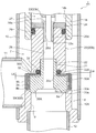
- FIG. 2 is an enlarged vertical sectional view of a main part of the electric valve shown in FIG.
- FIGS. 3 to 8 are enlarged vertical sectional views of a main part for explaining the configuration and operation of the motor-operated valve shown in FIGS.
- the gap formed between the members, the separation distance between the members, etc. are larger than the dimensions of each constituent member for easy understanding of the invention and for convenience of drawing. Or it may be drawn small.
- the motor-driven valve 1 of the illustrated embodiment is suitable for use as, for example, an expansion valve in a heat pump air conditioning system, and the fluid (refrigerant) is bidirectional (first flow direction from side to bottom and from bottom to side). In the second flow direction).
- the motor-operated valve 1 of the present embodiment includes a planetary gear speed reduction mechanism between the rotor and the screw feed mechanism so as to increase the axial force of the main valve body and improve the sealing performance. It has become.
- the motor-operated valve 1 includes a valve body 10 having a cylindrical base body 10A made of a sheet metal, a main valve body 20 disposed in the valve body 10 so as to be movable up and down, and the main valve body 20 to move up and down. And a stepping motor 50 attached to the upper side of the valve body 10.
- a valve chamber 7 is formed on the cylindrical base body 10A of the valve body 10, and a lateral first inlet / outlet (conduit joint) 11 that opens to the valve chamber 7 is attached to a side portion thereof.
- a main valve comprising a vertically oriented valve port 9 that opens from the lower side to the valve chamber 7 at the lower end of the cylindrical base body 10A (that is, the bottom of the valve chamber 7), and an inner peripheral corner of the upper end of the valve port 9.
- a stepped valve seat member 8 (a lower outer periphery of a stepped valve seat member 8b formed of an upper end outer peripheral top portion of the valve port 9 disposed outside the main valve seat 8a via a seat 8a and an inverted frustoconical surface 8c.
- a second inlet / outlet (conduit joint) 12 connected to the valve port 9 is attached to the valve seat member 8.
- a stepped cylindrical base 13 is attached to the upper surface opening of the cylindrical base body 10 ⁇ / b> A, and a cylindrical shape with a ceiling portion that constitutes a part of the stepping motor 50 is attached to the upper end of the cylindrical base 13.
- the lower end of the can 58 is hermetically joined by welding or the like.
- a cylindrical holding member 14 with a partition wall 14c is fixed to the inner peripheral side of the cylindrical base 13 by press-fitting or the like, and a bearing member provided with a female screw 15i on the lower inner periphery is provided above the cylindrical holding member 14. 15 is fixed by caulking.
- a spring chamber 14a Immediately above the partition wall 14c of the cylindrical holding member 14 is a spring chamber 14a in which a valve opening spring 25 made of a compression coil spring is accommodated.
- the main valve body 20 has a generally cylindrical shape with a step, and is a poppet valve that moves up and down in the vertical direction with respect to the main valve seat 8a to open and close the valve port 9.
- the main valve body 20 has a slightly large-diameter main valve body portion 20 ⁇ / b> A that opens and closes the valve port 9 in contact with and separates from the main valve seat 8 a of the valve seat member 8.
- a strut portion 20B having a slightly smaller diameter is provided continuously above the main valve body portion 20A, and the upper portion thereof is slidably fitted into the valve body guide hole 14b below the partition wall 14c in the cylindrical holding member 14.
- the lower half diameter fitting formed in the strut part 20B which consists of a cylindrical member is substantially upper half part of the small diameter fitting cylinder part 21 protruding upwardly at the main valve body part 20A (the upper surface center).
- the main valve body portion 20A and the strut portion 20B are integrated (that is, can move up and down integrally), and the main valve body portion 20A has a small-diameter fitting cylinder.
- a reverse frustoconical seal surface 20a that is substantially in line contact with the main valve seat 8a is provided on the outer peripheral portion of the lower surface of the main valve body 20A so as to obtain a required sealing property.
- the sub-valve body 30 for opening and closing the valve port 9 is slidable in the vertical direction on the lower outer peripheral side of the main valve body 20 (specifically, on the outer peripheral side of the main valve body portion 20A). It is arranged. That is, as described above, the main valve seat 8a in which the main valve body portion 20A (the seal surface 20a thereof) contacts and is separated from the upper inner peripheral side (corner portion) of the valve seat member 8 (valve port 9) in the valve body 10. Is provided on the upper outer peripheral side (top) of the valve seat member 8 via the inverted truncated cone surface 8c on the upper outer peripheral side (top) of the sub-valve element 30 (the lower outer flange-shaped portion 30B).
- a sub-valve seat 8b with which a lower surface (in this example, a flat surface perpendicular to the up-down direction) 30a contacts and separates is provided.
- the sub-valve body 30 has a cylindrical shape with a lower outer flange-shaped portion 30B that is inserted on the outer periphery of the lower portion of the main valve body 20 (the outer periphery of the main valve body portion 20A) so as to be movable up and down (with a predetermined gap).
- the lower outer flange-shaped portion 30B (the seal surface (the lower surface of the lower outer flange-shaped portion 30B) 30a) moves up and down in the vertical direction with respect to the sub-valve seat 8b. Open and close.
- the auxiliary valve body 30 is formed with a fitting insertion hole 30 c into which the small-diameter fitting cylinder portion 21 is slidably inserted in the ceiling portion.
- the main valve body 20 has a substantially hat-shaped cross section with a slightly larger diameter than the main valve body portion 20A. That is, the sub-valve body 30 is formed to have an outer diameter slightly larger than that of the main valve body portion 20A, and is externally inserted with a predetermined gap on the outer peripheral side of the main valve body portion 20A.
- the main valve body portion 20A has a cylindrical portion 30A with a lower outer flange-shaped portion 30B that is slightly shorter in length than the main valve body portion 20A, and has a ceiling portion (in other words, a cylindrical portion 30A) of the sub-valve body 30.
- the portion extending from the upper end to the outer periphery of the small-diameter fitting tube portion 21 of the main valve body portion 20A through the gap between the upper surface of the main valve body portion 20A and the lower surface of the strut portion 20B is the main valve body portion 20A.
- the upper inner hook-shaped hook portion 30 ⁇ / b> C is engaged with the upper surface.
- the O-ring (elastic member) 33 as a biasing member that constantly biases the sub-valve element 30 downward (in the valve closing direction) is accommodated in a compressed state (via a washer 32 described later).
- the sub-valve element 30 is slidable in the vertical direction on the main valve element 20 and is retained by being locked by the ceiling (upper inner hook-like hook part 30C).
- the valve port 9 is closed before the main valve body 20 (in other words, the seal surface 20a of the main valve body 20 is closed to the valve seat member 8 (valve port 9). )
- the dimension and shape of each part are set so that the sealing surface 30a of the sub valve body 30 is seated on the sub valve seat 8b of the valve seat member 8 (valve port 9)). (Details later).
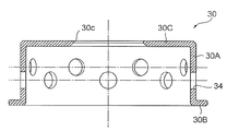
- the cylindrical portion 30A of the auxiliary valve body 30 is provided with a bleed hole 34 formed of a plurality of (or even one) through holes formed at substantially equal angular intervals, for example (see FIG. 9), a filter 35 made of a cylindrical porous body made of, for example, a sintered metal is disposed (exterior) on the outer periphery of the cylindrical portion 30A (the bleed hole 34).
- the filter 35 is formed so that the length in the vertical direction (axis O direction) is slightly longer than the cylindrical portion 30 ⁇ / b> A, and the inner end is between the sub valve body 30 and the O ring 33.
- a washer 32 made of a thin plate is disposed.
- the filter 35 mounted on the cylindrical portion 30A uses the elastic force (compression force) of the O-ring 33 to lower the upper outer flange-shaped portion 30B (the upper surface thereof) and the washer 32 (the lower surface of the outer end). Narrow pressure is maintained between.
- the filter 35 has a function of allowing refrigerant to pass but not allowing foreign matter to pass therethrough.
- the filter 35 includes a mesh member in which a wire is woven in a mesh shape, and a plurality of mesh members. It can be comprised from the laminated body laminated
- the stepping motor 50 disposed on the upper side of the valve main body 10 has a two-phase coil portion including a yoke 51, a bobbin 52, a coil 53, a resin mold 54, etc. It has a stator 55 that is externally fitted and fixed, and a rotor 57 that is rotatably arranged in a can 58 and has a rotor support member 56 fixed to the inside of the upper portion thereof. Further, on the inner peripheral side of the rotor 57, a sun gear 41 provided integrally with the rotor support member 56 and a fixing ring fixed to the tip of the cylindrical body 14d fixed to the upper end of the cylindrical holding member 14 are provided.
- a mysterious planetary gear type reduction mechanism 40 comprising an output shaft 46 and the like fixed to the gear 45 is attached.
- the number of teeth of the fixed ring gear 47 is different from the number of teeth of the output gear 45.
- the lower portion of the support shaft 49 is inserted into a hole provided in the upper portion of the output shaft 46, and the carrier 44 and the sun gear 41 (rotor support member 56) are inserted into the support shaft 49.
- a support member 48 having substantially the same diameter as the inner diameter of the can 58 is disposed, and the upper portion of the support shaft 49 is a support member. It is inserted through a hole provided at the center of 48.
- the output shaft 46 of the mysterious planetary gear speed reduction mechanism 40 is rotatably inserted into the upper portion of the bearing member 15, and the rotation of the output shaft 46 is provided on the bearing member 15 and is screwed into the screw 15 i. It is transmitted to the rotary vertical movement shaft 17 provided with the screw 17e.
- a slit-like fitting portion 46a is provided at the lower portion of the output shaft 46, and a plate-like portion 17a that is slidably fitted to the slit-like fitting portion 46a is provided on the upper portion of the rotary vertical movement shaft 17 so as to project.
- a stepped cylindrical thrust transmission member 23 is disposed below the rotary vertical movement shaft 17 and the thrust downward of the rotary vertical movement shaft 17 is transmitted through the ball 18 and the ball seat 19. . Since the ball 18 is interposed, only the downward thrust is transmitted from the rotary vertical shaft 17 to the thrust transmission member 23 even if the rotary vertical shaft 17 is lowered while rotating, and the rotational force is Not transmitted.
- the thrust transmission member 23 includes, in order from the top, a large-diameter upper portion 23a in which the ball seat 19 is fitted on the inner periphery, an intermediate body portion 23b that is slidably inserted into the partition wall 14c of the cylindrical holding member 14, A small diameter lower portion 23c having a diameter smaller than that of the intermediate body portion 23b, and a through hole 26d constituting an upper portion of a pressure equalizing passage 26 described later and a plurality of horizontal holes 26e opened in a back pressure chamber 27 described later are formed therein. Is provided. The upper end opening of the through hole 26d is closed by the ball seat 19.
- the small diameter lower portion 23c of the thrust transmission member 23 is fitted and fixed to the upper fitting hole 20d of the stepped cylindrical main valve body 20 (its strut portion 20B) by press fitting or the like, and the main valve body 20 and the thrust transmission member 23 are fixed. Can be moved up and down together.
- a pressing member 24 is sandwiched and fixed between the upper end surface of the main valve body 20 (the strut portion 20B thereof) and the lower end step portion of the intermediate body portion 23b of the thrust transmission member 23 when the small diameter lower portion 23c is press-fitted. ing.
- a sealing member 29 is mounted between the holding member 24 and the annular groove provided in the upper end portion of the main valve body 20 (the strut portion 20B) and the valve body guide hole 14b of the cylindrical holding member 14.
- a valve opening spring 25 made of a compression coil spring is mounted with its lower end in contact with the partition wall 14c.
- the lifting spring receiver 28 having a hook-like hooking portion (upper hooking portion 28a, lower hooking portion 28b) on the upper and lower sides. Is distributed.
- the upper hooking portion 28 a of the pulling spring receiving body 28 is placed on the valve opening spring 25, and the lower hooking portion 28 b is configured to hook the lower end step portion of the large-diameter upper portion 23 a of the thrust transmission member 23.
- the screw feed mechanism is constituted by the bearing member 15 provided with the female screw 15i and the rotary vertical movement shaft 17 provided with the male screw 17e.
- the stepping motor 50 rotor 57
- the rotary vertical movement shaft 17 is rotated downward, for example, by screw feed by the female screw 15i and the external screw 17e, and the thrust of the rotary vertical movement shaft 17 is rotated.
- the thrust transmission member 23 and the main valve body 20 are pushed down against the urging force of the valve opening spring 25, and finally the seal surface 20a of the main valve body portion 20A is pressed against the main valve seat 8a and the valve port 9 Is closed.
- the stepping motor 50 (rotor 57) is rotated in the other direction, for example, the rotary vertical shaft 17 is rotated while being rotated by the screw feed by the female screw 15i and the external screw 17e, and accordingly, the thrust transmission member 23 and the main valve body 20 are pulled up by the urging force of the valve opening spring 25, and the seal surface 20a of the main valve body portion 20A is lifted (raised) from the main valve seat 8a to open the valve port 9.
- a back pressure chamber 27 is defined above the main valve body 20 and between the pressing member 24 and the partition wall 14c of the cylindrical holding member 14. Further, in the main valve body 20 (the main valve body portion 20 ⁇ / b> A and the strut portion 20 ⁇ / b> B), a stepped pressure equalizing passage 26 that communicates the front end portion (lower end portion) of the main valve body 20 and the back pressure chamber 27. Is provided. The pressure equalizing passage 26 communicates with the back pressure chamber 27 together with the vertical hole 26d and the horizontal hole 26e of the thrust transmission member 23 described above.
- the diameter Da of the back pressure chamber 27 and the diameter Dc of the valve port 9 are set to be substantially the same.
- the valve closing operation is completed and the main valve body 20 and the sub-valve body 30 are located at the lowest position, that is, the main valve body 20 is seated on the main valve seat 8a.
- the O-ring 33 is pushed against the strut portion 20B of the main valve body 20 when the sub-valve body 30 is seated and pressed against the sub-valve seat 8b and is closed (when fully closed).
- a gap La is provided between the lower surface of the strut portion 20B of the main valve body 20 and the upper surface of the upper inner hook-like hook portion 30C of the sub-valve body 30 by being contracted, and the main valve body portion of the main valve body 20
- a gap Lb is provided between the upper surface of 20A and the lower surface of the upper inner hook-like hook portion 30C of the sub-valve body 30.
- the stepping motor 50 (rotor 57) is rotated in one direction, and the main valve body 20 is moved down with the sub-valve body 30.
- the sub valve body 30 is pushed down by the urging force (elastic force) of the O-ring 33.
- the upper inner hook-shaped hook portion 30C (the lower surface) is abutted and locked to the main valve body portion 20A (the upper surface thereof), and the lower surface of the strut portion 20B of the main valve body 20 and the upper inner hook shape of the sub-valve body 30 are A gap La + Lb is formed between the upper surface of the hook portion 30C.
- the lower end of the sub-valve element 30 (the lower outer flange-shaped part 30B) is higher than the lower end of the main valve element 20 (the main valve element part 20A).
- the coolant and the foreign substances (metal powder, shavings, abrasives, sludge, etc.) contained therein are located along the inverted truncated cone surface 8c formed at the upper end of the valve seat member 8 so that the sub-valve 30 and the auxiliary valve seat 8b and between the main valve body 20 and the main valve seat 8a.
- a foreign substance having a size (diameter) of 10 to 300 ⁇ m is assumed.
- the main valve body 20 is further moved downward from the state where the main valve body 20 shown in FIG. 3 is slightly opened and the sub-valve body 30 is slightly opened.
- the valve closing operation until the sub valve body 30 is seated on the sub valve seat 8b and closes (2), that is, the gap formed between the sub valve body 30 and the sub valve seat 8b becomes gradually smaller.
- the foreign matter contained in the refrigerant is dammed up in a minute gap formed between the sub-valve element 30 and the sub-valve seat 8b, and the part indicated by the arrow E1 in FIG.
- the small gap formed between the sub-valve body 30 and the sub-valve seat 8b accumulates on the upstream side (outer peripheral side) and becomes clogged.
- the sub-valve element 30 is seated on the sub-valve seat 8b and closed, the foreign matter is blocked by the sub-valve element 30 and is downstream (here, the main valve body 20 and the main valve seat 8a on the inner peripheral side). Will not flow.
- a part of the refrigerant Is a filter 35 provided on the outer periphery of the sub-valve body 30, a bleed hole 34 provided in the sub-valve body 30, between the sub-valve body 30 (the inner circumference) and the main valve body 20 (the outer circumference).
- the seal surface 20a of the main valve body 20 is seated on the main valve seat 8a and closed as shown in FIG.
- the refrigerant stops flowing (the flow rate becomes 0).
- the main valve body 20 is strongly pressed against the main valve seat 8a by a high axial force by the mysterious planetary gear speed reduction mechanism 40.
- the O-ring 33 is compressed by the strut portion 20B of the main valve body 20 by the gap Lb, so that the lower surface of the strut portion 20B of the main valve body 20 and the upper inner hook shape of the sub-valve body 30 are formed.
- the gap formed between the upper surface of the hook portion 30C is only La to Lb, and the upper surface of the main valve body portion 20A of the main valve body 20 and the lower surface of the upper inner hook-like hook portion 30C of the sub-valve body 30 In the meantime, the gap Lb is opened, and the auxiliary valve body 30 is pressed against the auxiliary valve seat 8b by the urging force (elastic force) of the O-ring 33.
- the stepping motor 50 (rotor 57) is rotated in the other direction, and thereby the main valve body 20 is pulled up as shown in FIG.
- the main valve body 20 is slightly opened from the closed state, whereby the main valve body of the main valve body 20 is urged by the urging force (elastic force) of the O-ring 33.
- the lower surface of the upper inner hook-like hook portion 30C of the sub-valve body 30 is abutted and locked to the upper surface of the portion 20A, and the lower surface of the strut portion 20B of the main valve body 20 and the upper inner hook-like hook portion of the sub-valve body 30
- the gap formed between the upper surface of 30C is changed from La to La + Lb, and the auxiliary valve body 30 remains closed, but the pressing force by the O-ring (elastic member) 33 is reduced.
- a part of the refrigerant (a minute flow rate) is a filter 35 provided on the outer periphery of the sub-valve element 30 and a bleed provided on the sub-valve element 30. It flows out to the valve port 9 side through the hole 34, the gap between the sub-valve body 30 (the inner circumference) and the main valve body 20 (the outer circumference), between the main valve body 20 and the main valve seat 8a. Become. Therefore, the balance between the push-down force (force acting in the valve closing direction) acting on the sub-valve body 30 and the push-up force (force acting in the valve opening direction) acting on the sub-valve body 30 in the valve-closed state is canceled. Thus, the push-down force acting on the closed valve body 30 is further reduced.
- FIGS. 7 and 8 states corresponding to FIGS. 3 and 4 at the time of the second flow from the bottom to the side.
- the main valve body 20 is moved downward from the state where the main valve body 20 is slightly opened and the sub-valve body 30 is slightly opened, and is formed between the sub-valve body 30 and the sub-valve seat 8b.
- the gap becomes gradually smaller and finally becomes 0, the foreign matter contained in the refrigerant is blocked by a minute gap formed between the sub-valve body 30 and the sub-valve seat 8b.
- a part of the refrigerant (a minute flow rate) is a gap between the main valve body 20 and the main valve seat 8a, a gap between the sub valve body 30 (the inner circumference) and the main valve body 20 (the outer circumference), a sub-flow Since it flows out to the valve chamber 7 side through the bleed hole 34 provided in the valve body 30 and the filter 35 provided on the outer periphery of the sub-valve body 30, the push-down force acting on the sub-valve body 30 (force acting in the valve closing direction) ) And the pushing-up force (force acting in the valve opening direction) acting on the sub-valve body 30 is balanced (differential pressure is canceled), and foreign matter is clogged in the gap between the main valve body 20 and the main valve seat 8a. There is nothing.
- the main valve body 20 is further lowered from the slightly opened state shown in FIG. 8, the main valve body 20 is seated on the main valve seat 8a and is closed, and the refrigerant does not flow.
- the O-ring 33 is compressed by the strut portion 20B of the main valve body 20 by the gap Lb, so that the lower surface of the strut portion 20B of the main valve body 20 and the upper inner hook shape of the sub-valve body 30 are formed.
- the gap formed between the upper surface of the hook portion 30C is only La to Lb, and the upper surface of the main valve body portion 20A of the main valve body 20 and the lower surface of the upper inner hook-like hook portion 30C of the sub-valve body 30 In the meantime, the gap Lb is opened, and the auxiliary valve body 30 is pressed against the auxiliary valve seat 8 b by the urging force (elastic force) of the O-ring (elastic member) 33.
- the auxiliary valve body 30 that closes the valve port 9 before the main valve body 20 is provided on the outer periphery of the main valve body 20.
- the fluid refrigerant
- the sub-valve body 30 is closed from there, the fluid (refrigerant) does not substantially flow.
- Foreign matter is not caught between the main valve body 20 and the main valve seat 8a. Therefore, even if the main valve body 20 is closed and strongly pressed against the main valve seat 8a, the main valve body 20 and the main valve seat 8a are not damaged or dented.
- the rotor 57 and the screw feed mechanism (the bearing member 15 provided with the female screw 15i, A strange planetary gear speed reduction mechanism 40 is interposed between the rotary vertical movement shaft 17) provided with the male screw 17e, and the axial force of the main valve body 20, that is, the main valve body 20 is applied to the main valve seat 8a.
- the pressing force is increased, it is difficult to cause a situation in which foreign matter contained in the fluid (refrigerant) is caught between the main valve body 20 and the main valve seat 8a and strongly pressed against them.
- the main valve seat 8a, the sub-valve seat 8b, the main valve body 20, and the sub-valve body 30 can be prevented from being scratched or dented. As a result, the valve leakage is effectively prevented and the valve is closed. Reliability can be improved.
- the sub valve body 30 closes the valve port 9 on the outer periphery of the sub valve body 30, until the main valve body 20 closes the valve port 9 (in other words, for example, after the main valve body 20 opens the valve port 9 and the sub-valve body 30 closes the valve port 9), a filter 35 that connects the valve port 9 and the valve chamber 7 is provided. Therefore, the fluid (refrigerant) passes through the filter 35 when the valve is opened. Therefore, the differential pressure acting on the sub-valve body 30 can be canceled, and foreign matter contained in the passing fluid (refrigerant) is captured by the filter 35, and the foreign matter contained in the fluid (refrigerant) is separated from the main valve body 20. It is difficult to cause a situation where the main valve seat 8a is caught between the main valve seats 8a and strongly pressed against them.
- the filter 35 for allowing the fluid (refrigerant) to pass through and trapping foreign matter contained in the fluid (refrigerant) is disposed outside the subvalve body 30 (the cylindrical portion 30A). However, for example, it may of course be arranged on the inner side (inner circumference) of the auxiliary valve body 30 (the cylindrical portion 30A). Further, the filter 35 is held and fixed to the sub-valve body 30 by using the washer 32, but needless to say that the method for holding and fixing the filter 35 is not limited to the above-described form.
- FIG. 10 to FIG. 13 are enlarged vertical sectional views of the essential parts for explaining the configuration and operation of the second embodiment of the motor-operated valve according to the present invention.
- the motor-operated valve 2 of the illustrated second embodiment has substantially the same configuration as the motor-operated valve 1 of the first embodiment shown in FIGS. 1 to 9 except for the main valve body, the sub-valve body, and the periphery of the valve port. .
- portions corresponding to the respective portions of the motor-operated valve 1 of the first embodiment and portions having similar functions are denoted by common reference numerals and redundant description is omitted, and the following description will focus on the differences.
- valve seat member 8 fixed to the lower end portion of the cylindrical base body 10A (that is, the bottom portion of the valve chamber 7) has a vertical valve port 9 that opens from the lower side to the valve chamber 7, and the valve port 9
- a main valve seat 8a composed of an inner peripheral corner of the upper end is formed, and a ring having a rectangular cross section made of, for example, sintered metal is formed on an outer peripheral step portion 36a formed on the outer side of the main valve seat 8a in the valve port 9.
- a filter 36 made of a porous material is fitted and fixed by press-fitting or the like, and the upper surface of the filter 36 is brought into contact with and separated from the subvalve element 31 (the seal surface (the lower surface of the lower outer flange-shaped portion 31B) 31a).
- the auxiliary valve seat 8b is used.
- a sub-valve body 31 for opening and closing the valve port 9 is disposed on the lower outer peripheral side of the main valve body 20 (specifically, on the outer peripheral side of the main valve body portion 20A).
- This sub-valve element 31 includes a truncated cone-shaped part 31A with a lower outer flange-shaped part 31B that is extrapolated (with a predetermined gap) on the lower outer periphery of the main valve body 20 (the outer periphery of the main valve body part 20A).
- the lower outer flange-shaped portion 31B (the seal surface (the lower surface of the lower outer flange-shaped portion 31B) 31a) moves up and down in the vertical direction with respect to the auxiliary valve seat 8b provided in the filter 36.
- the valve port 9 is opened and closed.
- the sub-valve element 31 is made of, for example, a SUS304CSP-3 / 4H material and is made of a spring plate material that has been subjected to annealing for removing stress (in other words, elastically deformable). Has been.
- the sub-valve body 31 has an outer diameter slightly larger than that of the main valve body portion 20A.
- the sub-valve body 31 is extrapolated with a predetermined gap on the outer peripheral side of the main valve body portion 20A, and has a length in the vertical direction (axis O direction).
- 31C is narrowly held and fixed between the main valve body portion 20A (the upper surface outer periphery thereof) and the strut portion 20B (the lower surface outer periphery thereof) of the main valve body 20.
- the sub-valve body 31 itself is made of an elastic spring plate material, and an urging member (such as an O-ring) that constantly urges the sub-valve body 31 downward (in the valve closing direction) Omitted, the sub-valve element 31 (the lower outer flange-shaped part 31B) is always urged downward (in the valve-closing direction) by the elastic force (elastic repulsive force) of the sub-valve element 31.
- an urging member such as an O-ring
- the sub valve body 31 closes the valve port 9 before the main valve body 20 when the main valve body 20 is closed from the open state.
- the seal surface 30a of the sub valve body 30 is The size and shape of each part are set so as to be seated on the secondary valve seat 8b of the valve port 9) (details will be described later).
- the sub-valve body 31 (the lower outer flange portion 31 ⁇ / b> B) is elastically seated on the valve port 9 outside the main valve seat 8 a.
- a fluid (refrigerant) flows between the valve chamber 7 and the valve port 9 through the filter 36 and the main valve body 20 (the main valve body portion 20A) and the main valve seat 8a (details will be described later).
- the valve closing operation is completed and the main valve body 20 and the sub-valve body 31 are positioned at the lowest position, that is, the main valve body 20 is seated on the main valve seat 8a and pressed.
- the sub-valve element 31 is seated and pressed against the sub-valve seat 8b and both are closed (when fully closed), the sub-valve element 31 is elastically deformed, and its lower outer flange-shaped portion 31B is pushed upward by a displacement Lc from the natural state (also referred to as a no-load state).
- the stepping motor 50 (rotor 57) is rotated in one direction, and the main valve body 20 is lowered with the sub-valve body 31.
- the sub-valve element 31 is in an unloaded state, so that the lower outer flange-shaped part 31B is moved by the elastic restoring force (elastic repulsive force) of the sub-valve element 31 itself. Pressed down.
- the lower end of the sub-valve element 31 (the lower outer flange-shaped part 31B) is higher than the lower end of the main valve element 20 (the main valve element portion 20A).
- the coolant and the foreign substances (metal powder, shavings, abrasives, sludge, etc.) contained therein are located along the inverted truncated cone surface 8c formed at the upper end of the valve seat member 8 so that the sub-valve 31 and the auxiliary valve seat 8b and between the main valve body 20 and the main valve seat 8a.
- the main valve body 20 is further moved down as shown in FIG.
- the gap formed between the sub valve body 31 and the sub valve seat 8b becomes gradually smaller.
- the foreign matter contained in the refrigerant is dammed up in a minute gap formed between the sub-valve element 31 and the sub-valve seat 8b, and the part indicated by the arrow E1 in FIG.
- the small gap formed between the sub valve body 31 and the sub valve seat 8b accumulates on the upstream side (outer peripheral side) and becomes clogged.
- the seal surface 20a of the main valve body 20 is seated on the main valve seat 8a and closed as shown in FIG.
- the refrigerant stops flowing (the flow rate becomes 0).
- the main valve body 20 is strongly pressed against the main valve seat 8a by a high axial force by the mysterious planetary gear speed reduction mechanism 40.
- the sub-valve element 31 is elastically deformed (along with the downward movement of the main valve element 20), and the lower outer flange-shaped portion 31B is pushed upward by a displacement amount Lc from the natural state.
- the valve body 31 (the lower outer flange portion 31B) is pressed against the auxiliary valve seat 8b by the elastic force of the auxiliary valve body 31 itself.
- the stepping motor 50 (rotor 57) is rotated in the other direction, whereby the main valve body 20 is pulled up and opened as shown in FIG. I speak.
- the sub-valve body 31 (the lower outer flange portion 31B) is closed by the elastic restoring force (elastic repulsive force) of the sub-valve body 31 itself.
- the pressing force due to the elastic force of the sub-valve element 31 itself is small.
- a part of the refrigerant (a minute flow rate) is a filter 36 having a sub-valve seat 8 b provided on the outer peripheral portion of the valve port 9, and the main valve body. It flows out to the valve port 9 side through between 20 and the main valve seat 8a. Therefore, the balance between the push-down force (force acting in the valve closing direction) acting on the sub-valve body 31 and the push-up force (force acting in the valve opening direction) acting on the sub-valve body 31 in the valve closing state is balanced (the differential pressure is canceled). Thus, the push-down force acting on the closed sub valve body 31 is further reduced.
- an elastically deformable sub-valve body 31 that closes the valve port 9 before the main valve body 20 is provided on the outer periphery of the main valve body 20. Therefore, when the sub-valve element 31 is in the slightly opened state, foreign matter contained in the fluid (refrigerant) is blocked by the sub-valve element 31, and when the sub-valve element 31 is closed from there, the fluid (refrigerant) is substantially Therefore, the foreign matter is not caught between the main valve body 20 and the main valve seat 8a. Therefore, even if the main valve body 20 is closed and strongly pressed against the main valve seat 8a, the main valve body 20 and the main valve seat 8a are not damaged or dented.
- the foreign matter contained in the fluid is caught between the main valve body 20 and the main valve seat 8a and strongly resists them.
- the main valve seat 8a, the sub-valve seat 8b, the main valve body 20, and the sub-valve body 31 can be prevented from being scratched or dented, resulting in valve leakage. It can prevent effectively and can improve the reliability of valve closing.
- the number of parts can be reduced and the parts configuration can be simplified.
- the urging member (O-ring or the like) that constantly urges the sub-valve element 31 downward (in the valve closing direction) is omitted, but for example, FIG. 1 to FIG.
- an O-ring elastic member
- an elastic member such as reference
- a seal member 39 made of an O-ring or ring-shaped packing may be attached.
- the mysterious planet is placed between the rotor 57 and the screw feed mechanism in order to strongly press the main valve body 20 against the main valve seat 8a (in other words, improve the sealing performance).
- the gear speed reduction type with the gear type speed reduction mechanism 40 interposed is described as an example, the present invention is a linear motion type (detailed structure and structure) with the mysterious planetary gear type speed reduction mechanism 40 and related parts removed.
- the description of the operation can be applied to the above-mentioned Patent Document 1 if necessary.
- the motor-operated valve according to the present invention is not limited to the configuration of each of the above-described embodiments.
- the configuration around the main valve body and the sub-valve body can be variously changed.
Landscapes
- Engineering & Computer Science (AREA)
- General Engineering & Computer Science (AREA)
- Mechanical Engineering (AREA)
- Electrically Driven Valve-Operating Means (AREA)
- Details Of Valves (AREA)
Abstract
流通する流体(冷媒)中に含まれる異物が弁体と弁シートとの間に噛み込まれてそれらに強く 押し付けられないようにでき、もって、弁シートや弁体に傷、打痕等がつかず、弁漏れを生じ難 くできる信頼性の高い電動弁を提供する。 ロータ(57)の回転をねじ送り機構により主弁体(20)の上下動に変換するようにされた 電動弁(1)であって、主弁体(20)周りに、弁口(9)を開閉するための副弁体(30)が 配設され、該副弁体(30)は、主弁体(20)が弁口(9)を閉弁する際、弁口(9)を主弁 体(20)より先に閉弁するとともに、副弁体(30)及び弁口(9)の少なくとも一方に、副 弁体(30)が弁口(9)を閉弁した後、主弁体(20)が弁口(9)を閉弁するまで、弁口(9) と弁室(7)とを連通せしめるフィルタ(35)が設けられている。
Description
本発明は、ヒートポンプ式冷暖房システム等に使用するのに好適な電動弁に係り、特に、流通する流体(冷媒)中に含まれる金属粉等の異物に起因する不具合が生じ難くされた電動弁に関する。
従来より、電動弁として、弁室、複数の入出口、弁シート、及び弁口等が設けられた弁本体と、前記弁室に上下動可能に配在された弁体と、該弁体を前記弁シートに対して接離させるための、例えば雄ねじが設けられた弁軸及び雌ねじが設けられたガイドステム等からなるねじ送り機構と、前記弁本体に密封接合された円筒状のキャンと、該キャンの内側に回転可能に配在されたロータ及び該キャンの外側に配在されたステータからなるステッピングモータとを備え、前記ロータの回転をねじ送り機構により弁体の上下動に変換して、弁体のリフト量(弁開度)を変化させることにより、弁口を通過する流体(冷媒)の流量を調整するようにされたものが知られている(例えば特許文献1参照)。
かかる電動弁では、通常、ロータの回転を減速することなくねじ送り機構に伝達するようされているが(このタイプを直動式の電動弁と称する)、近年においては、シール圧を上げるべく、例えば特許文献2に見られるように、ロータとねじ送り機構との間に遊星歯車式減速機構を介装し、ロータの回転を減速してねじ送り機構に伝達し、もって、弁体の軸力、すなわち、弁体の弁シートへの押し付け力を増大するようにしたものが知られている(このタイプを歯車減速式の電動弁と称する)。
しかしながら、上記のような従来の電動弁では、弁体のリフト量が微小(微開)であるとき、流体(冷媒)中に含まれる異物(金属粉、削りカス、研磨材、スラッジ等)が弁体部分に詰まり気味となり、この微開状態から閉弁すると、詰まり気味の異物が弁体と弁シートとの間に噛み込まれ、この異物噛み込みにより弁漏れしやすくなるという問題がある。
特に、弁体の弁シートへの押し付け力を増大するようにした歯車減速式の電動弁では、閉弁時に、異物が弁体と弁シートとの間に噛み込まれると、その噛み込まれた異物が弁体により弁シートに強く押し付けられるので、弁シートや弁体(のシール面)に傷、打痕等がつき、弁漏れが生じやすくなる。
そこで、従来、上記した如くの歯車減速式の電動弁を例えば緊急遮断弁として使用する場合には、当該電動弁を直列に2台繋いで安全性を高めるようにしている。しかし、かかる方策では、システムへの弁の組み込みや配管等を考慮すると、電動弁を1台だけで済ます場合と比べてコストが大幅に増大し、しかも、異物噛み込み自体は発生し得るので、費用対効果の面で良策ではない。
本発明は、上記事情に鑑みてなされたもので、その目的とするところは、流通する流体(冷媒)中に含まれる異物が弁体と弁シートとの間に噛み込まれてそれらに強く押し付けられないようにでき、もって、弁シートや弁体に傷、打痕等がつかず、弁漏れを生じ難くできる信頼性の高い電動弁を提供することにある。
前記目的を達成すべく、本発明に係る電動弁は、基本的には、弁室、複数の入出口、及び弁口が設けられた弁本体と、前記弁口を開閉すべく前記弁室に上下動可能に配在された主弁体と、前記弁本体に接合された筒状のキャンと、該キャンの内側に回転可能に配在されたロータ及び該キャンの外側に配在されたステータからなるステッピングモータと、前記ロータの回転を前記主弁体の上下動に変換するねじ送り機構とを備え、前記主弁体に、前記弁口を開閉するための副弁体が配設され、該副弁体は、前記主弁体が前記弁口を閉弁する際、前記弁口を前記主弁体より先に閉弁するとともに、前記副弁体及び前記弁口の少なくとも一方に、前記副弁体が前記弁口を閉弁した後、前記主弁体が前記弁口を閉弁するまで、前記弁口と前記弁室とを連通せしめるフィルタが設けられていることを特徴としている。
好ましい態様では、前記弁本体における前記弁口に、前記主弁体が接離する主弁シートと前記副弁体が接離する副弁シートとが別個に設けられる。
更に好ましい態様では、前記主弁体は、前記主弁シートに対して垂直方向に上下動して前記弁口を開閉するようにされ、前記副弁体は、前記副弁シートに対して垂直方向に上下動して前記弁口を開閉するようにされる。
他の好ましい態様では、前記弁本体における前記弁口に、前記主弁体が接離する主弁シートが設けられるとともに、前記副弁体が接離する副弁シートを持つ前記フィルタが固着される。
別の好ましい態様では、前記主弁体に前記副弁体が上下方向に摺動可能かつ抜止係止されて配在される。
更に好ましい態様では、前記副弁体は、前記主弁体に所定の隙間を持って上下動可能かつ抜止係止されて配在されるとともに、貫通穴からなるブリード穴を持つ円筒状部を有し、該円筒状部における前記ブリード穴の外側もしくは内側に前記フィルタが配在される。
更に好ましい態様では、前記円筒状部の下部に、前記弁口に接離する下側外鍔状部が設けられる。
更に好ましい態様では、前記副弁体と前記主弁体との間に、弾性力により前記副弁体を閉弁方向に付勢する弾性部材が介装される。
更に好ましい態様では、前記フィルタは、前記下側外鍔状部と、前記弾性部材と前記副弁体との間に介装されたワッシャとの間で狭圧保持される。
更に好ましい態様では、前記主弁体は、前記弁口を開閉する主弁体部と、該主弁体部の上側に連設されるストラット部材とを有し、前記主弁体部の上面と前記ストラット部の下面との間に、前記円筒状部の上部に設けられた上側内鍔状引っ掛け部が上下動可能かつ抜止係止されて配在されるとともに、前記ストラット部と前記上側内鍔状引っ掛け部との間に、弾性力により前記副弁体を閉弁方向に付勢する弾性部材が介装される。
更に好ましい態様では、前記円筒状部の下部に、前記弁口に接離する下側外鍔状部が設けられ、前記フィルタは、前記下側外鍔状部と、前記弾性部材と前記上側内鍔状引っ掛け部との間に介装されたワッシャとの間で狭圧保持される。
別の好ましい態様では、前記主弁体に、一端が前記主弁体に固定され、他端が前記弁口に設けられた前記フィルタに弾性的に接離する前記副弁体が配在される。
更に好ましい態様では、前記副弁体と前記主弁体との間に、弾性力により前記副弁体を閉弁方向に付勢する弾性部材が介装される。
別の好ましい態様では、前記主弁体と前記副弁体との間にシール部材が介装される。
別の好ましい態様では、前記ロータと前記ねじ送り機構との間に遊星歯車式減速機構が設けられる。
本発明に係る電動弁では、主弁体に、弁口を主弁体より先に閉弁する副弁体が設けられているので、副弁体が微開状態にあるとき、流体(冷媒)中に含まれる異物が副弁体により堰き止められ、そこから副弁体が閉弁すると流体(冷媒)が実質的に流れなくなるため、異物が主弁体と主弁シートとの間に噛み込まれることはない。したがって、主弁体が閉弁して主弁シートに強く押し付けられても、主弁体や主弁シートに傷、打痕等はつくことはない。
また、異物は副弁体と副弁シートとの間に噛み込まれるおそれがあるが、副弁体はOリング等の弾性部材もしくは副弁体自体の弾性力により付勢されているだけであるので、その押し付け力はさほど強くない。したがって、副弁体と副弁シートに傷、打痕等はつかない。
また、異物が副弁体と副弁シートとの間に噛み込まれて、それらの間に隙間が生じても、主弁体は閉弁しているので、弁漏れは生じない。
このように、本発明によれば、流体(冷媒)中に含まれる異物が主弁体と主弁シートとの間に噛み込まれてそれらに強く押し付けられるような事態を生じ難くでき、そのため、弁シートや弁体に傷、打痕等がつかないようにでき、その結果、弁漏れを効果的に防止して、閉弁の信頼性を向上させることができる。
また、本発明に係る電動弁では、副弁体及び弁口の少なくとも一方に、副弁体が弁口を閉弁した後、主弁体が弁口を閉弁するまで(換言すれば、主弁体が弁口を開弁した後、副弁体が弁口を閉弁している間)、弁口と弁室とを連通せしめるフィルタが設けられているので、開弁時に、流体(冷媒)がフィルタを通過する。そのため、副弁体に作用する差圧をキャンセルできるとともに、通過する流体(冷媒)中に含まれる異物が当該フィルタにより捕捉され、流体(冷媒)中に含まれる異物が主弁体と主弁シートとの間に噛み込まれてそれらに強く押し付けられるような事態を生じ難くできる。
以下、本発明の実施形態を図面を参照しながら説明する。
[第1実施形態]
図1は、本発明に係る電動弁の第1実施形態の全閉状態を示す全体縦断面図、図2は、図1に示される電動弁の要部拡大縦断面図である。また、図3~図8は、図1及び図2に示される電動弁の構成並びに動作説明に供される要部拡大縦断面図である。
図1は、本発明に係る電動弁の第1実施形態の全閉状態を示す全体縦断面図、図2は、図1に示される電動弁の要部拡大縦断面図である。また、図3~図8は、図1及び図2に示される電動弁の構成並びに動作説明に供される要部拡大縦断面図である。
なお、本明細書において、上下、左右、前後等の位置、方向を表わす記述は、説明が煩瑣になるのを避けるために図面に従って便宜上付けたものであり、実際にシステムに組み込まれた状態での位置、方向を指すとは限らない。
また、各図において、部材間に形成される隙間や部材間の離隔距離等は、発明の理解を容易にするため、また、作図上の便宜を図るため、各構成部材の寸法に比べて大きくあるいは小さく描かれている場合がある。
図示実施形態の電動弁1は、例えばヒートポンプ式冷暖房システムにおいて膨張弁として使用するのに好適なもので、流体(冷媒)が双方向(横から下への第1流れ方向と下から横への第2流れ方向)に流されるようになっている。また、本実施形態の電動弁1は、後述するように、ロータとねじ送り機構との間に遊星歯車式減速機構を介装し、主弁体の軸力を高めてシール性を向上させるようになっている。
電動弁1は、板金製の筒状基体10Aを有する弁本体10と、この弁本体10内に上下動可能に配在された主弁体20と、この主弁体20を上下動させるべく、弁本体10の上側に取り付けられたステッピングモータ50とを備える。
弁本体10の筒状基体10Aには、弁室7が形成されるとともに、その側部に、弁室7に開口する横向きの第1入出口(導管継手)11が取り付けられている。また、筒状基体10Aの下端部(つまり、弁室7の底部)に、下側から弁室7に開口する縦向きの弁口9、該弁口9の上端内周角部からなる主弁シート8a、逆円錐台面8cを介して該主弁シート8aの外側に配備された該弁口9の上端外周頂部からなる副弁シート8bが形成された段付きの弁座部材8(の下部外周に設けられた外鍔状部)が溶接等により固着されており、この弁座部材8に、前記弁口9に連なる第2入出口(導管継手)12が取り付けられている。
筒状基体10Aの上面開口部には、段付きの筒状基台13が取着され、この筒状基台13の上端部には、ステッピングモータ50の一部を構成する天井部付き円筒状のキャン58の下端部が溶接等により密封接合されている。筒状基台13の内周側には隔壁14c付き筒状保持部材14が圧入等により固定され、この筒状保持部材14の上部には、下部内周にめねじ15iが設けられた軸受部材15がかしめ係止固定されている。筒状保持部材14の隔壁14cの直上は、圧縮コイルばねからなる開弁ばね25が収納されるばね室14aとされている。
また、前記主弁体20は、概略段付き円筒状を有し、主弁シート8aに対して垂直方向に上下動して弁口9を開閉するポペット弁とされている。この主弁体20は、図2を参照すればよくわかるように、前記弁座部材8の主弁シート8aに接離して弁口9を開閉する若干大径の主弁体部20Aと、この主弁体部20Aの上側に連設され、その上部が筒状保持部材14における隔壁14cより下側の弁体ガイド穴14bに摺動自在に嵌挿される若干小径のストラット部20Bとを有する。本例では、主弁体部20A(の上面中央)に上向きに突設された小径嵌合筒部21の略上半部が、円筒状部材からなるストラット部20Bに形成された下部大径嵌合穴22に圧入等により嵌合固定されており、主弁体部20Aとストラット部20Bとは一体(つまり、一体に上下動可能)とされるとともに、主弁体部20Aの小径嵌合筒部21の下半部周りで主弁体部20Aの上面とストラット部20Bの下面との間に所定の大きさの間隙(後述する上側内鍔状引っ掛け部30Cが相対的に上下動可能な間隙)が形成されている。主弁体部20Aの下面外周部には、所要のシール性が得られるように、前記主弁シート8aに対して実質的に線接触する逆円錐台状のシール面20aが設けられている。
そして、本実施形態では、前記主弁体20の下部外周側(詳しくは、主弁体部20Aの外周側)に、弁口9を開閉するための副弁体30が上下方向に摺動可能に配設されている。すなわち、上記した如くに、弁本体10における弁座部材8(弁口9)の上部内周側(角部)に、主弁体部20A(のシール面20a)が接離する主弁シート8aが設けられ、逆円錐台面8cを介してこの主弁シート8aとは別個に、弁座部材8の上部外周側(頂部)に、副弁体30のシール面(下側外鍔状部30Bの下面(本例では、上下方向に対して垂直な平坦面))30aが接離する副弁シート8bが設けられている。この副弁体30は、主弁体20の下部外周(主弁体部20Aの外周)に(所定の隙間を持って)上下動可能に外挿された下側外鍔状部30B付き円筒状部30Aを有し、当該下側外鍔状部30B(のシール面(下側外鍔状部30Bの下面)30a)が前記副弁シート8bに対して垂直方向に上下動して弁口9を開閉するようにされている。
より詳細には、図9を併せて参照すればよく分かるように、前記副弁体30は、天井部に小径嵌合筒部21が摺動自在に挿入される嵌挿穴30cが形成されるとともに、主弁体20における主弁体部20Aより若干大径の断面略ハット状を有している。すなわち、この副弁体30は、外径が主弁体部20Aより若干大きく形成され、主弁体部20Aの外周側に所定の隙間を持って上下動可能に外挿されるとともに、上下方向(軸線O方向)長さが主弁体部20Aより若干短い下側外鍔状部30B付きの円筒状部30Aを有するとともに、この副弁体30の天井部(換言すれば、円筒状部30Aの上端から、主弁体部20Aの上面とストラット部20Bの下面との間の間隙を通って主弁体部20Aの小径嵌合筒部21の外周まで延びる部分)は、主弁体部20Aの上面に係止される上側内鍔状引っ掛け部30Cとなっている。また、主弁体20におけるストラット部20Bの下面中央(つまり、主弁体部20Aの小径嵌合筒部21の外周)に設けられた環状凹部22Aと前記上側内鍔状引っ掛け部30Cとの間には、(後述するワッシャ32を介して)前記副弁体30を常時下方(閉弁方向)に付勢する付勢部材としてのOリング(弾性部材)33が圧縮状態で収容されている。
前記副弁体30は、前述したように、前記主弁体20に上下方向に摺動可能かつその天井部(上側内鍔状引っ掛け部30C)により抜止係止されて配在されるとともに、主弁体20が開弁状態から閉弁せしめられる際、弁口9を主弁体20より先に閉弁する(換言すれば、主弁体20のシール面20aが弁座部材8(弁口9)の主弁シート8aに着座する前に、副弁体30のシール面30aが弁座部材8(弁口9)の副弁シート8bに着座する)ように、各部の寸法形状が設定されている(後で詳述)。
また、本実施形態では、前記副弁体30における円筒状部30Aに、例えば略等角度間隔で形成された複数個(1個でもよい)の貫通穴からなるブリード穴34が設けられるとともに(図9を併せて参照)、その円筒状部30A(におけるブリード穴34)の外周に、例えば焼結金属等で作製された円筒状の多孔体からなるフィルタ35が配在(外装)されている。本例では、前記フィルタ35は、上下方向(軸線O方向)長さが円筒状部30Aより僅かに長く形成されており、前記副弁体30と前記Oリング33との間に、内端がOリング33と上側内鍔状引っ掛け部30C(の上面)との間に介装され、外端が円筒状部30Aの外側まで延びてフィルタ35(の上面)上に載置されるリング状の薄板で構成されるワッシャ32が配在されている。前記円筒状部30Aに外装されたフィルタ35は、前記Oリング33の弾性力(圧縮力)を利用して前記下側外鍔状部30B(の上面)と前記ワッシャ32(の外端下面)との間で狭圧保持されている。
前記フィルタ35は、冷媒は通過させるが異物は通過させない機能を有するものであり、焼結金属や発泡部材等の多孔体の他に、線材を網目状に織り込んだメッシュ部材、複数のメッシュ部材を積層させた積層体、及び、複数の開口を形成した板状部材等から構成できる。
これにより、副弁体30が弁口9を閉弁した後、主弁体20が弁口9を閉弁するまで(換言すれば、主弁体20が弁口9を開弁した後、副弁体30が弁口9を閉弁している間)は、副弁体30(の円筒状部30A)の外周に設けられたフィルタ35、副弁体30(の円筒状部30A)に設けられたブリード穴34、副弁体30(の円筒状部30Aの内周)と主弁体20(の主弁体部20Aの外周)との間の隙間、主弁体20(の主弁体部20A)と主弁シート8aとの間を通して、流体(冷媒)が弁室7と弁口9との間で流通する(後で詳述)。
一方、弁本体10(の筒状基体10A)の上側に配置されたステッピングモータ50は、ヨーク51、ボビン52、コイル53、樹脂モールド54等からなる2相のコイル部を有し、キャン58に外嵌固定されたステータ55と、キャン58内に回転自在に配在され、ロータ支持部材56がその上部内側に固着されたロータ57とを有している。また、ロータ57の内周側には、ロータ支持部材56に一体的に設けられた太陽歯車41、筒状保持部材14の上端部に固着された筒状体14dの先端に固定された固定リング歯車47、前記太陽歯車41及び固定リング歯車47に歯合する遊星歯車42、該遊星歯車42を回転自在に支持するキャリア44、前記遊星歯車42に歯合するリング状の出力歯車45、該出力歯車45に固着された出力軸46等からなる不思議遊星歯車式減速機構40が付設されている。前記固定リング歯車47の歯数は、前記出力歯車45の歯数とは異なるようにされている。
前記出力軸46の上部に設けられた穴に支持軸49の下部が挿通されており、該支持軸49に前記キャリア44、太陽歯車41(ロータ支持部材56)が挿通されている。
キャン58内部において、該キャン58の天井部とロータ支持部材56との間には、該キャン58の内径とほぼ同一径を有する支持部材48が配置され、前記支持軸49の上部は、支持部材48の中心部に設けられた穴に挿通されている。
前記不思議遊星歯車式減速機構40の出力軸46は、軸受部材15の上部に回転自在に嵌挿され、この出力軸46の回転が、前記軸受部材15に設けられためねじ15iに螺合するおねじ17eが設けられた回転上下動軸17に伝達される。出力軸46の下部にはスリット状嵌合部46aが設けられ、回転上下動軸17の上部には前記スリット状嵌合部46aに摺動自在に嵌合する板状部17aが突設されており、出力軸46が回転すると、前記めねじ15iとおねじ17eによるねじ送りにより回転上下動軸17が回転しながら上下動せしめられる。
回転上下動軸17の下方には、該回転上下動軸17の下方への推力がボール18、ボール受座19を介して伝達される段付き筒状の推力伝達部材23が配在されている。なお、ボール18を介在させていることにより、回転上下動軸17が回転しながら下降しても、回転上下動軸17から推力伝達部材23へは下方への推力のみが伝達され、回転力は伝達されない。
推力伝達部材23は、上から順に、内周に前記ボール受座19が嵌め込まれた大径上部23a、前記筒状保持部材14の隔壁14cに摺動自在に挿通せしめられる中間胴部23b、該中間胴部23bより小径の小径下部23cからなっており、その内部に、後述する均圧通路26の上部を構成する貫通孔26d及び後述する背圧室27に開口する複数個の横孔26eが設けられている。なお、貫通孔26dの上端開口はボール受座19により閉塞されている。
推力伝達部材23の小径下部23cは、段付き円筒状の主弁体20(のストラット部20B)の上部嵌合穴20dに圧入等により嵌合固定され、主弁体20と推力伝達部材23とは一体に上下動せしめられる。主弁体20(のストラット部20B)の上端面と推力伝達部材23の中間胴部23bの下端段差部との間には、前記小径下部23cの圧入時において押さえ部材24が挟み込まれて固定されている。この押さえ部材24と主弁体20(のストラット部20B)の上端部に設けられた環状溝と前記筒状保持部材14の弁体ガイド穴14bとの間には、Oリング、リング状パッキンからなるシール部材29が装着されている。
また、筒状保持部材14の隔壁14cより上側のばね室14aには、圧縮コイルばねからなる開弁ばね25がその下端を隔壁14cに当接させた状態で縮装されるとともに、この開弁ばね25の付勢力(引き上げ力)を推力伝達部材23を介して主弁体20に伝達すべく、上下に鍔状引っ掛け部(上引っ掛け部28a、下引っ掛け部28b)を有する引き上げばね受け体28が配在されている。引き上げばね受け体28の上引っ掛け部28aは、開弁ばね25の上に乗せられ、下引っ掛け部28bは推力伝達部材23の大径上部23aの下端段差部を掛止するようになっている。
したがって、本実施形態では、めねじ15iが設けられた軸受部材15とおねじ17eが設けられた回転上下動軸17等でねじ送り機構が構成されている。ステッピングモータ50(ロータ57)が一方向に回転せしめられるとき、前記めねじ15iとおねじ17eによるねじ送りにより回転上下動軸17が回転しながら例えば下動せしめられ、回転上下動軸17の推力により、推力伝達部材23及び主弁体20が開弁ばね25の付勢力に抗して押し下げられ、最終的には主弁体部20Aのシール面20aが主弁シート8aに押し付けられて弁口9が閉じられる。
それに対し、ステッピングモータ50(ロータ57)が他方向に回転せしめられるときには、前記めねじ15iとおねじ17eによるねじ送りにより回転上下動軸17が回転しながら例えば上動せしめられ、それに伴い推力伝達部材23及び主弁体20が開弁ばね25の付勢力によって引き上げられ、主弁体部20Aのシール面20aが主弁シート8aからリフト(上昇)して弁口9を開くようにされている。
なお、副弁体30を含めた詳細な動作説明は後述する。
本実施形態では、前記主弁体20の上方で押さえ部材24と筒状保持部材14の隔壁14cとの間に、背圧室27が画成されている。また、主弁体20(の主弁体部20A及びストラット部20B)内には、該主弁体20の先端部(下端部)と背圧室27とを連通させる段付きの均圧通路26が設けられている。この均圧通路26は、前記した推力伝達部材23の縦穴26d及び横孔26eとともに背圧室27に連通している。ここでは、閉弁状態において主弁体20に作用する押し下げ力(閉弁方向に働く力)と主弁体20に作用する押し上げ力(開弁方向に働く力)とをバランス(差圧をキャンセル)させるべく、背圧室27の室径Daと弁口9の口径Dcとは略同一に設定されている。
次に、上記した如くの構成を有する電動弁1における副弁体30を含めた開閉動作を図2~図8を参照しながら説明する。
まず、図2及び図5に示される如くに、閉弁動作が完了して主弁体20及び副弁体30が最も下方に位置する状態、すなわち、主弁体20が主弁シート8aに着座して押し付けられ、副弁体30が副弁シート8bに着座して押し付けられ、共に閉弁しているとき(全閉時)には、Oリング33が主弁体20のストラット部20Bに押し縮められて該主弁体20のストラット部20Bの下面と副弁体30の上側内鍔状引っ掛け部30Cの上面との間には間隙Laが空けられるとともに、主弁体20の主弁体部20Aの上面と副弁体30の上側内鍔状引っ掛け部30Cの下面との間に間隙Lbが空けられる。
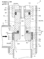
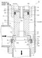
一方、図3に示される如くに、横から下への第1流れ時において、ステッピングモータ50(ロータ57)が一方向に回転せしめられて、主弁体20が副弁体30を伴って下動しているとき、すなわち、主弁体20及び副弁体30が共に開状態の閉弁動作中(1)においては、Oリング33の付勢力(弾性力)により副弁体30が押し下げられて、主弁体部20A(の上面)に上側内鍔状引っ掛け部30C(の下面)が当接係止され、主弁体20のストラット部20Bの下面と副弁体30の上側内鍔状引っ掛け部30Cの上面との間には間隙La+Lbが空けられている。
この閉弁動作中(1)において、本例では、主弁体20(の主弁体部20A)の下端より副弁体30(の下側外鍔状部30B)の下端の方が上側に位置しており、弁座部材8の上端に形成された逆円錐台面8cに沿うように、冷媒及びその中に含まれる異物(金属粉、削りカス、研磨材、スラッジ等)は、副弁体30と副弁シート8bとの間、及び、主弁体20と主弁シート8aとの間を通って流される。なお、本実施形態では、10~300μmの大きさ(直径)の異物を想定している。
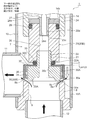
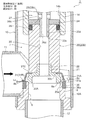
続いて、図3に示される、主弁体20が小開、副弁体30が微開している状態から、図4に示される如くに、主弁体20がさらに下動せしめられて、副弁体30が副弁シート8bに着座して閉弁するまでの閉弁動作中(2)、すなわち、副弁体30と副弁シート8bとの間に形成される隙間が次第に小さくなって最終的に0になるときには、冷媒中に含まれる異物が副弁体30と副弁シート8bとの間に形成される微小隙間に堰き止められ、図4においてE1矢印で示される部位、すなわち、副弁体30と副弁シート8bとの間に形成される微小隙間の上流側(外周側)に溜まって詰まり気味となる。副弁体30が副弁シート8bに着座して閉弁したときには、異物は副弁体30によりブロックされて下流側(ここでは、内周側の主弁体20及び主弁シート8a側)には流れなくなる。
このようにして副弁体30が微開状態から閉弁するまでの閉弁動作中(2)においては、主弁体20は小開状態から微開状態へと下動し、主弁体20を通過する冷媒流量が次第に小量となり、副弁体30が閉弁すると、冷媒はほとんど流れなくなり、流量が実質的に0となるが、ここで、本例では、冷媒の一部(微小流量)は、副弁体30の外周に設けられたフィルタ35、副弁体30に設けられたブリード穴34、副弁体30(の内周)と主弁体20(の外周)との間の隙間、主弁体20と主弁シート8aとの間を通って弁口9側に流れ出る。ただし、この閉弁動作中(2)においてブリード穴34等を通って弁口9側に流れ出る冷媒中に含まれる異物は、ブリード穴34の外側に設けられたフィルタ35により(ブリード穴34に侵入する前に)捕捉されて(ブロックされて)下流側(ここでは、内周側の主弁体20及び主弁シート8a側)には流れなくなる。
続いて、主弁体20が図4に示される微開状態からさらに下動せしめられると、図5に示される如くに、主弁体20のシール面20aが主弁シート8aに着座して閉弁し、冷媒は流れなくなる(流量が0となる)。この場合、主弁体20は、不思議遊星歯車式減速機構40による高い軸力で主弁シート8aに強く押し付けられる。このとき、前述したように、Oリング33が主弁体20のストラット部20Bにより間隙Lb分だけ押し縮められて該主弁体20のストラット部20Bの下面と副弁体30の上側内鍔状引っ掛け部30Cの上面との間に形成される間隙がLa+LbからLaのみになるとともに、主弁体20の主弁体部20Aの上面と副弁体30の上側内鍔状引っ掛け部30Cの下面との間に間隙Lbが空けられ、副弁体30がOリング33の付勢力(弾性力)により副弁シート8bに押し付けられる。
ここで、副弁体30が副弁シート8bに着座して閉弁した際(図4に示される状態)、異物が副弁体30と副弁シート8bとの間に噛み込まれている場合には、Lb分圧縮されるOリング33の付勢力により異物が副弁体30と副弁シート8bとに押し付けられるが、その押し付け力はさほど強くない。したがって、副弁体30と副弁シート8bに傷、打痕等はつかない。
また、このときは、主弁体20が微開状態から閉弁しても、異物は副弁体30もしくはフィルタ35でブロックされていて、冷媒は実質的に流れなくなっているので、主弁体20と主弁シート8aとの間に異物を噛み込むことはない。したがって、主弁体20が主弁シート8aに不思議遊星歯車式減速機構40による高い軸力で強く押し付けられても、主弁体20や主弁シート8aに傷、打痕等はつくことはない。
図5に示される全閉状態から開弁するにあたっては、ステッピングモータ50(ロータ57)が他方向に回転せしめられ、これによって、図6に示される如くに、主弁体20が引き上げられる。この場合、主弁体20が間隙Lb分引き上げられると、主弁体20が閉弁状態から微開し、これによって、Oリング33の付勢力(弾性力)により主弁体20の主弁体部20Aの上面に副弁体30の上側内鍔状引っ掛け部30Cの下面が当接係止されるとともに、主弁体20のストラット部20Bの下面と副弁体30の上側内鍔状引っ掛け部30Cの上面との間に形成される間隙がLaからLa+Lbになり、副弁体30は閉弁したままであるが、Oリング(弾性部材)33による押し付け力は小さくなる。
また、このとき、図4に基づき説明したように、本例では、冷媒の一部(微小流量)が、副弁体30の外周に設けられたフィルタ35、副弁体30に設けられたブリード穴34、副弁体30(の内周)と主弁体20(の外周)との間の隙間、主弁体20と主弁シート8aとの間を通って弁口9側に流れ出るようになる。そのため、閉弁状態において副弁体30に作用する押し下げ力(閉弁方向に働く力)と副弁体30に作用する押し上げ力(開弁方向に働く力)とがバランス(差圧がキャンセル)され、閉弁状態の副弁体30に作用する押し下げ力はさらに小さくなる。
この図6に示される状態からさらに主弁体20が引き上げられると、(主弁体20の主弁体部20Aによって)副弁体30のシール面30aが副弁シート8bから離れ、図3に示される如くの、主弁体20が小開、副弁体30が微開している状態となる。
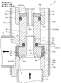
以上は、横から下への第1流れ時についての説明であるが、下から横への第2流れ時においても、図7、図8(図3、図4に対応する状態)に示される如くに、主弁体20が小開、副弁体30が微開している状態から、主弁体20が下動せしめられて、副弁体30と副弁シート8bとの間に形成される隙間が次第に小さくなって最終的に0になるときには、冷媒中に含まれる異物が副弁体30と副弁シート8bとの間に形成される微小隙間に堰き止められ、図8においてE2矢印で示される部位、すなわち、主弁体20と主弁シート8aとの間に形成される隙間より下流側(外周側)で、副弁体30と副弁シート8bとの間に形成される微小隙間の上流側(内周側)に溜まって詰まり気味となる。
かかる副弁体30が微開状態から閉弁するまでの閉弁動作中(2)においては、主弁体20は小開状態から微開状態へと下動し、主弁体20を通過する冷媒流量が次第に小量となり、副弁体30が閉弁すると、冷媒はほとんど流れなくなる。また、冷媒の一部(微小流量)は、主弁体20と主弁シート8aとの間、副弁体30(の内周)と主弁体20(の外周)との間の隙間、副弁体30に設けられたブリード穴34、副弁体30の外周に設けられたフィルタ35を通って弁室7側に流れ出るので、副弁体30に作用する押し下げ力(閉弁方向に働く力)と副弁体30に作用する押し上げ力(開弁方向に働く力)とがバランス(差圧がキャンセル)されるとともに、異物が主弁体20と主弁シート8aとの間の隙間に詰まることはない。
続いて、主弁体20が図8に示される微開状態からさらに下動せしめられると、主弁体20が主弁シート8aに着座して閉弁し、冷媒は流れなくなる。このとき、前述したように、Oリング33が主弁体20のストラット部20Bにより間隙Lb分だけ押し縮められて該主弁体20のストラット部20Bの下面と副弁体30の上側内鍔状引っ掛け部30Cの上面との間に形成される間隙がLa+LbからLaのみになるとともに、主弁体20の主弁体部20Aの上面と副弁体30の上側内鍔状引っ掛け部30Cの下面との間に間隙Lbが空けられ、副弁体30がOリング(弾性部材)33の付勢力(弾性力)により副弁シート8bに押し付けられる。
ここで、本第2流れ時においても、副弁体30が副弁シート8bに着座して閉弁した際(図8に示される状態)、異物が副弁体30と副弁シート8bとの間に噛み込まれている場合には、Lb分圧縮されるOリング33により異物が副弁体30と副弁シート8bとに押し付けられるが、その押し付け力はさほど強くない。したがって、副弁体30と副弁シート8bに傷、打痕等はつかない。
また、このときは、主弁体20が微開状態から閉弁しても、冷媒は実質的に流れなくなっているので、主弁体20と主弁シート8aとの間に異物を噛み込むことはほとんどない。したがって、主弁体20が主弁シート8aに強く押し付けられても、主弁体20や主弁シート8aに傷、打痕等はつくことはない。
このように、本実施形態の電動弁1においては、主弁体20の外周に、弁口9を主弁体20より先に閉弁する副弁体30が設けられているので、副弁体30が微開状態にあるとき、流体(冷媒)中に含まれる異物が副弁体30により堰き止められ、そこから副弁体30が閉弁すると流体(冷媒)が実質的に流れなくなるため、異物が主弁体20と主弁シート8aとの間に噛み込まれることはない。したがって、主弁体20が閉弁して主弁シート8aに強く押し付けられても、主弁体20や主弁シート8aに傷、打痕等はつくことはない。
また、異物は副弁体30と副弁シート8bとの間に噛み込まれるおそれがあるが、副弁体30はOリング33(の弾性力)により付勢されているだけであるので、その押し付け力はさほど強くない。したがって、副弁体30と副弁シート8bに傷、打痕等はつかない。
また、異物が副弁体30と副弁シート8bとの間に噛み込まれて、それらの間に隙間が生じても、主弁体20は閉弁しているので、弁漏れは生じない。
このように、本第1実施形態の歯車減速式の電動弁1では、シール性を高めて弁漏れを確実に防ぐべく、ロータ57とねじ送り機構(めねじ15iが設けられた軸受部材15、おねじ17eが設けられた回転上下動軸17)との間に不思議遊星歯車式減速機構40を介装し、主弁体20の軸力、すなわち、主弁体20の主弁シート8aへの押し付け力を増大するようにしたものにおいて、流体(冷媒)中に含まれる異物が主弁体20と主弁シート8aとの間に噛み込まれてそれらに強く押し付けられるような事態を生じ難くでき、そのため、主弁シート8a、副弁シート8bや主弁体20、副弁体30に傷、打痕等がつかないようにでき、その結果、弁漏れを効果的に防止して、閉弁の信頼性を向上させることができる。
また、本実施形態の電動弁1においては、副弁体30の外周に、副弁体30が弁口9を閉弁した後、主弁体20が弁口9を閉弁するまで(換言すれば、主弁体20が弁口9を開弁した後、副弁体30が弁口9を閉弁している間)、弁口9と弁室7とを連通せしめるフィルタ35が設けられているので、開弁時に、流体(冷媒)がフィルタ35を通過する。そのため、副弁体30に作用する差圧をキャンセルできるとともに、通過する流体(冷媒)中に含まれる異物が当該フィルタ35により捕捉され、流体(冷媒)中に含まれる異物が主弁体20と主弁シート8aとの間に噛み込まれてそれらに強く押し付けられるような事態を生じ難くできる。
なお、上記第1実施形態では、流体(冷媒)を通過させるとともに流体(冷媒)中に含まれる異物を捕捉するためのフィルタ35を、副弁体30(の円筒状部30A)の外側に配置しているが、例えば、副弁体30(の円筒状部30A)の内側(内周)に配置してもよいことは勿論である。また、前記フィルタ35をワッシャ32を使用して副弁体30に保持固定しているが、前記フィルタ35の保持・固定方法は、上記形態に限られないことは詳述するまでも無い。
[第2実施形態]
図10~図13は、本発明に係る電動弁の第2実施形態の構成並びに動作説明に供される要部拡大縦断面図である。
図10~図13は、本発明に係る電動弁の第2実施形態の構成並びに動作説明に供される要部拡大縦断面図である。
図示第2実施形態の電動弁2は、図1~図9に示される第1実施形態の電動弁1と、主弁体及び副弁体、並びに、弁口周り以外は略同様な構成である。そのため、第1実施形態の電動弁1の各部に対応する部分並びに同様の機能を有する部分には共通の符号を付して重複説明を省略し、以下においては、相違点を中心に説明する。
図示実施形態の電動弁2において、上記第1実施形態の電動弁1とは逆に、流体(冷媒)を通過させるとともに流体(冷媒)中に含まれる異物を捕捉するためのフィルタ36が、(副弁体30に代えて)弁座部材8の弁口9に設けられている。
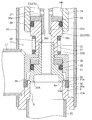
詳しくは、筒状基体10Aの下端部(つまり、弁室7の底部)に固着された弁座部材8は、下側から弁室7に開口する縦向きの弁口9、該弁口9の上端内周角部からなる主弁シート8aが形成されるとともに、弁口9における主弁シート8aの外側に形成された外周段差部36aに、例えば焼結金属等で作製された断面矩形のリング状の多孔体からなるフィルタ36が圧入等により嵌め込まれて固着され、そのフィルタ36の上面が、副弁体31(のシール面(下側外鍔状部31Bの下面)31a)が接離する副弁シート8bとされている。
また、本実施形態では、前記主弁体20の下部外周側(詳しくは、主弁体部20Aの外周側)に、弁口9を開閉するための副弁体31が配設されている。この副弁体31は、主弁体20の下部外周(主弁体部20Aの外周)に(所定の隙間を持って)外挿された下側外鍔状部31B付き円錐台状部31Aを有し、当該下側外鍔状部31B(のシール面(下側外鍔状部31Bの下面)31a)が前記フィルタ36に設けられた副弁シート8bに対して垂直方向に上下動して弁口9を開閉するようにされている。
より詳細には、前記副弁体31は、例えばSUS304CSP-3/4H材で作製され、応力除去のための焼きなましが施された弾性を有する(換言すれば、弾性変形可能な)ばね板材で構成されている。この副弁体31は、外径が主弁体部20Aより若干大きく形成され、主弁体部20Aの外周側に所定の隙間を持って外挿されるとともに、上下方向(軸線O方向)長さが主弁体部20Aより若干短い下側外鍔状部31B付きの円錐台状部31Aを有するとともに、この副弁体30の上端に(内向きに)設けられた上側内鍔状係止部31Cが、主弁体20における主弁体部20A(の上面外周)とストラット部20B(の下面外周)との間で狭圧保持されて固定されている。つまり、本例では、副弁体31自体が、弾性を有するばね板材で構成されており、当該副弁体31を常時下方(閉弁方向)に付勢する付勢部材(Oリング等)は省略され、当該副弁体31の弾性力(弾性反発力)によって当該副弁体31(の下側外鍔状部31B)を常時下方(閉弁方向)に付勢するようになっている。
本例でも、上記第1実施形態の電動弁1と同様、前記副弁体31は、主弁体20が開弁状態から閉弁せしめられる際、弁口9を主弁体20より先に閉弁する(換言すれば、主弁体20のシール面20aが弁座部材8(弁口9)の主弁シート8aに着座する前に、副弁体30のシール面30aが弁座部材8(弁口9)の副弁シート8bに着座する)ように、各部の寸法形状が設定されている(後で詳述)。
また、副弁体31が弁口9を閉弁した後、主弁体20が弁口9を閉弁するまで(換言すれば、主弁体20が弁口9を開弁した後、副弁体31が弁口9を閉弁している間)は、弁口9における主弁シート8aの外側に設けられ、副弁体31(の下側外鍔状部31B)が弾性的に着座するフィルタ36、主弁体20(の主弁体部20A)と主弁シート8aとの間を通して、流体(冷媒)が弁室7と弁口9との間で流通する(後で詳述)。
次に、上記した如くの構成を有する電動弁2における副弁体31を含めた開閉動作を図10~図13を参照しながら説明する。
まず、図12に示される如くに、閉弁動作が完了して主弁体20及び副弁体31が最も下方に位置する状態、すなわち、主弁体20が主弁シート8aに着座して押し付けられ、副弁体31が副弁シート8bに着座して押し付けられ、共に閉弁しているとき(全閉時)には、副弁体31は弾性変形せしめられ、その下側外鍔状部31Bが自然状態(無負荷状態ともいう)より変位量Lcだけ上側に押し上げられている。
一方、図10に示される如くに、横から下への第1流れ時において、ステッピングモータ50(ロータ57)が一方向に回転せしめられて、主弁体20が副弁体31を伴って下動している閉弁動作中(1)においては、副弁体31は無負荷状態となるので、副弁体31自体の弾性復元力(弾性反発力)によりその下側外鍔状部31Bが押し下げられている。この閉弁動作中(1)において、本例では、主弁体20(の主弁体部20A)の下端より副弁体31(の下側外鍔状部31B)の下端の方が上側に位置しており、弁座部材8の上端に形成された逆円錐台面8cに沿うように、冷媒及びその中に含まれる異物(金属粉、削りカス、研磨材、スラッジ等)は、副弁体31と副弁シート8bとの間、及び、主弁体20と主弁シート8aとの間を通って流される。
続いて、図10に示される、主弁体20が小開、副弁体31が微開している状態から、図11に示される如くに、主弁体20がさらに下動せしめられて、副弁体31が副弁シート8bに着座して閉弁するまでの閉弁動作中(2)、すなわち、副弁体31と副弁シート8bとの間に形成される隙間が次第に小さくなって最終的に0になるときには、冷媒中に含まれる異物が副弁体31と副弁シート8bとの間に形成される微小隙間に堰き止められ、図11においてE1矢印で示される部位、すなわち、副弁体31と副弁シート8bとの間に形成される微小隙間の上流側(外周側)に溜まって詰まり気味となる。副弁体31が副弁シート8bに着座して閉弁したときには、異物は副弁体31によりブロックされて下流側(ここでは、内周側の主弁体20及び主弁シート8a側)には流れなくなる。
このようにして副弁体31が微開状態から閉弁するまでの閉弁動作中(2)においては、主弁体20は小開状態から微開状態へと下動し、主弁体20を通過する冷媒流量が次第に小量となり、副弁体31が閉弁すると、冷媒はほとんど流れなくなり、流量が実質的に0となるが、ここで、本例では、冷媒の一部(微小流量)は、弁口9の外周部分に設けられた副弁シート8bを持つフィルタ36、主弁体20と主弁シート8aとの間を通って弁口9側に流れ出る。ただし、この閉弁動作中(2)において弁口9側に流れ出る冷媒中に含まれる異物は、前記副弁体31が着座する副弁シート8bを持つフィルタ36により捕捉されて(ブロックされて)下流側(ここでは、内周側の主弁体20及び主弁シート8a側)には流れなくなる。
続いて、主弁体20が図11に示される微開状態からさらに下動せしめられると、図12に示される如くに、主弁体20のシール面20aが主弁シート8aに着座して閉弁し、冷媒は流れなくなる(流量が0となる)。この場合、主弁体20は、不思議遊星歯車式減速機構40による高い軸力で主弁シート8aに強く押し付けられる。このとき、前述したように、副弁体31は(主弁体20の下動とともに)弾性変形せしめられ、その下側外鍔状部31Bが自然状態より変位量Lcだけ上側に押し上げられ、副弁体31(の下側外鍔状部31B)が当該副弁体31自体の弾性力により副弁シート8bに押し付けられる。
ここで、副弁体31が副弁シート8bに着座して閉弁した際(図11に示される状態)、異物が副弁体31と副弁シート8bとの間に噛み込まれている場合には、副弁体31自体の弾性力により異物が副弁体31と副弁シート8bとに押し付けられるが、その押し付け力はさほど強くない。したがって、副弁体31と副弁シート8bに傷、打痕等はつかない。
また、このときは、主弁体20が微開状態から閉弁しても、異物は副弁体31もしくはフィルタ36でブロックされていて、冷媒は実質的に流れなくなっているので、主弁体20と主弁シート8aとの間に異物を噛み込むことはない。したがって、主弁体20が主弁シート8aに不思議遊星歯車式減速機構40による高い軸力で強く押し付けられても、主弁体20や主弁シート8aに傷、打痕等はつくことはない。
図12に示される全閉状態から開弁するにあたっては、ステッピングモータ50(ロータ57)が他方向に回転せしめられ、これによって、図13に示される如くに、主弁体20が引き上げられて開弁する。この場合、主弁体20が変位量Lc分引き上げられるまでは、副弁体31自体の弾性復元力(弾性反発力)により副弁体31(の下側外鍔状部31B)は閉弁したままであるが、当該副弁体31自体の弾性力による押し付け力は小さくなる。
また、このとき、図11に基づき説明したように、本例では、冷媒の一部(微小流量)が、弁口9の外周部分に設けられた副弁シート8bを持つフィルタ36、主弁体20と主弁シート8aとの間を通って弁口9側に流れ出るようになる。そのため、閉弁状態において副弁体31に作用する押し下げ力(閉弁方向に働く力)と副弁体31に作用する押し上げ力(開弁方向に働く力)とがバランス(差圧がキャンセル)され、閉弁状態の副弁体31に作用する押し下げ力はさらに小さくなる。
この図13に示される状態からさらに主弁体20が引き上げられると、主弁体20とともに副弁体31が引き上げられ、副弁体31のシール面31aが副弁シート8bから離れて、副弁体31も開弁する。
以上は、横から下への第1流れ時についての説明であるが、下から横への第2流れ時においても、上記第1流れ時と同様の動作となり、図7、図8を用いて前述した第1実施形態の第2流れ時の作用効果と同様の作用効果が得られることは詳述するまでも無い。
このように、本第2実施形態の電動弁2においても、主弁体20の外周に、弁口9を主弁体20より先に閉弁する弾性変形可能な副弁体31が設けられているので、副弁体31が微開状態にあるとき、流体(冷媒)中に含まれる異物が副弁体31により堰き止められ、そこから副弁体31が閉弁すると流体(冷媒)が実質的に流れなくなるため、異物が主弁体20と主弁シート8aとの間に噛み込まれることはない。したがって、主弁体20が閉弁して主弁シート8aに強く押し付けられても、主弁体20や主弁シート8aに傷、打痕等はつくことはない。
また、異物は副弁体31と副弁シート8bとの間に噛み込まれるおそれがあるが、副弁体31は当該副弁体31自体の弾性力により付勢されているだけであるので、その押し付け力はさほど強くない。したがって、副弁体31と副弁シート8bに傷、打痕等はつかない。
また、異物が副弁体31と副弁シート8bとの間に噛み込まれて、それらの間に隙間が生じても、主弁体20は閉弁しているので、弁漏れは生じない。
このように、本第2実施形態の歯車減速式の電動弁2においても、流体(冷媒)中に含まれる異物が主弁体20と主弁シート8aとの間に噛み込まれてそれらに強く押し付けられるような事態を生じ難くでき、そのため、主弁シート8a、副弁シート8bや主弁体20、副弁体31に傷、打痕等がつかないようにでき、その結果、弁漏れを効果的に防止して、閉弁の信頼性を向上させることができる。
また、本第2実施形態の電動弁2においても、弁口9に、副弁体31が弁口9を閉弁した後、主弁体20が弁口9を閉弁するまで(換言すれば、主弁体20が弁口9を開弁した後、副弁体31が弁口9を閉弁している間)、弁口9と弁室7とを連通せしめるフィルタ36が設けられているので、開弁時に、流体(冷媒)がフィルタ36を通過する。そのため、副弁体31に作用する差圧をキャンセルできるとともに、通過する流体(冷媒)中に含まれる異物が当該フィルタ36により捕捉され、流体(冷媒)中に含まれる異物が主弁体20と主弁シート8aとの間に噛み込まれてそれらに強く押し付けられるような事態を生じ難くできる。
また、本第2実施形態の電動弁2においては、例えば上記第1実施形態の電動弁1と比べて、部品点数を削減できるととともに、部品構成を簡素化できるという効果もある。
なお、図10~図13に示される例では、副弁体31を常時下方(閉弁方向)に付勢する付勢部材(Oリング等)が省略されているが、例えば、図1~図9に示される第1実施形態の電動弁1と同様、主弁体20と副弁体31との間にOリング(弾性部材)を介装して副弁体31を常時下方(閉弁方向)に付勢してもよいし、図14及び図15に示される如くに、主弁体20と副弁体31との間にウェーブワッシャ33A(図14参照)や圧縮コイルばね33B(図15参照)等の弾性部材を介装してもよいことは勿論である。
また、例えば、図15に示される如くに、押さえ部材38等を用いて、主弁体20(の主弁体部20A)(の外周)と副弁体31(の内周)との間に、Oリング、リング状パッキンからなるシール部材39を装着してもよい。
また、上記実施形態の電動弁1、2では、主弁体20を主弁シート8aに強く押し付ける(換言すれば、シール性を向上させる)ためにロータ57とねじ送り機構との間に不思議遊星歯車式減速機構40を介装した歯車減速式のものを例示して説明したが、本発明は、不思議遊星歯車式減速機構40及びそれに関連する部分を取り除いた直動式のもの(詳細構造及び動作の説明は、必要なら上記特許文献1等を参照)にも適用できることは当然である。
また、本発明に係る電動弁は、上記した各実施形態の構成に限られないことは勿論であり、例えば主弁体及び副弁体周りの構成等は様々に変更可能である。
1 電動弁(第1実施形態)
2 電動弁(第2実施形態)
7 弁室
8 弁座部材
8a 主弁シート
8b 副弁シート
8c 逆円錐台面
9 弁口
10 弁本体
10A 筒状基体
11 第1入出口
12 第2入出口
20 主弁体
20a シール面
20A 主弁体部
20B ストラット部
21 小径嵌合筒部
22 下部大径嵌合穴
22A 環状凹部
30 副弁体(第1実施形態)
30a シール面
30c 嵌挿穴
30A 円筒状部
30B 下側外鍔状部
30C 上側内鍔状引っ掛け部
31 副弁体(第2実施形態)
31a シール面
31A 円錐台状部
31B 下側外鍔状部
31C 上側内鍔状係止部
32 ワッシャ
33 Oリング(弾性部材)
34 ブリード穴
35 フィルタ(第1実施形態)
36 フィルタ(第2実施形態)
36a 外周段差部
40 不思議遊星歯車式減速機構
50 ステッピングモータ
55 ステータ
57 ロータ
58 キャン
Claims (15)
- 弁室、複数の入出口、及び弁口が設けられた弁本体と、前記弁口を開閉すべく前記弁室に上下動可能に配在された主弁体と、前記弁本体に接合された筒状のキャンと、該キャンの内側に回転可能に配在されたロータ及び該キャンの外側に配在されたステータからなるステッピングモータと、前記ロータの回転を前記主弁体の上下動に変換するねじ送り機構とを備える電動弁であって、
前記主弁体に、前記弁口を開閉するための副弁体が配設され、該副弁体は、前記主弁体が前記弁口を閉弁する際、前記弁口を前記主弁体より先に閉弁するとともに、
前記副弁体及び前記弁口の少なくとも一方に、前記副弁体が前記弁口を閉弁した後、前記主弁体が前記弁口を閉弁するまで、前記弁口と前記弁室とを連通せしめるフィルタが設けられていることを特徴とする電動弁。 - 前記弁本体における前記弁口に、前記主弁体が接離する主弁シートと前記副弁体が接離する副弁シートとが別個に設けられていることを特徴とする請求項1に記載の電動弁。
- 前記主弁体は、前記主弁シートに対して垂直方向に上下動して前記弁口を開閉するようにされ、前記副弁体は、前記副弁シートに対して垂直方向に上下動して前記弁口を開閉するようにされていることを特徴とする請求項2に記載の電動弁。
- 前記弁本体における前記弁口に、前記主弁体が接離する主弁シートが設けられるとともに、前記副弁体が接離する副弁シートを持つ前記フィルタが固着されていることを特徴とする請求項1から3のいずれか一項に記載の電動弁。
- 前記主弁体に前記副弁体が上下方向に摺動可能かつ抜止係止されて配在されていることを特徴とする請求項1から4のいずれか一項に記載の電動弁。
- 前記副弁体は、前記主弁体に所定の隙間を持って上下動可能かつ抜止係止されて配在されるとともに、貫通穴からなるブリード穴を持つ円筒状部を有し、該円筒状部における前記ブリード穴の外側もしくは内側に前記フィルタが配在されていることを特徴とする請求項5に記載の電動弁。
- 前記円筒状部の下部に、前記弁口に接離する下側外鍔状部が設けられていることを特徴とする請求項6に記載の電動弁。
- 前記副弁体と前記主弁体との間に、弾性力により前記副弁体を閉弁方向に付勢する弾性部材が介装されていることを特徴とする請求項7に記載の電動弁。
- 前記フィルタは、前記下側外鍔状部と、前記弾性部材と前記副弁体との間に介装されたワッシャとの間で狭圧保持されていることを特徴とする請求項8に記載の電動弁。
- 前記主弁体は、前記弁口を開閉する主弁体部と、該主弁体部の上側に連設されるストラット部材とを有し、
前記主弁体部の上面と前記ストラット部の下面との間に、前記円筒状部の上部に設けられた上側内鍔状引っ掛け部が上下動可能かつ抜止係止されて配在されるとともに、前記ストラット部と前記上側内鍔状引っ掛け部との間に、弾性力により前記副弁体を閉弁方向に付勢する弾性部材が介装されていることを特徴とする請求項6に記載の電動弁。 - 前記円筒状部の下部に、前記弁口に接離する下側外鍔状部が設けられ、
前記フィルタは、前記下側外鍔状部と、前記弾性部材と前記上側内鍔状引っ掛け部との間に介装されたワッシャとの間で狭圧保持されていることを特徴とする請求項10に記載の電動弁。 - 前記主弁体に、一端が前記主弁体に固定され、他端が前記弁口に設けられた前記フィルタに弾性的に接離する前記副弁体が配在されていることを特徴とする請求項1から4のいずれか一項に記載の電動弁。
- 前記副弁体と前記主弁体との間に、弾性力により前記副弁体を閉弁方向に付勢する弾性部材が介装されていることを特徴とする請求項12に記載の電動弁。
- 前記主弁体と前記副弁体との間にシール部材が介装されていることを特徴とする請求項1から13のいずれか一項に記載の電動弁。
- 前記ロータと前記ねじ送り機構との間に遊星歯車式減速機構が設けられていることを特徴とする請求項1から14のいずれか一項に記載の電動弁。
Applications Claiming Priority (2)
| Application Number | Priority Date | Filing Date | Title |
|---|---|---|---|
| JP2018-107480 | 2018-06-05 | ||
| JP2018107480A JP7044246B2 (ja) | 2018-06-05 | 2018-06-05 | 電動弁 |
Publications (1)
| Publication Number | Publication Date |
|---|---|
| WO2019235149A1 true WO2019235149A1 (ja) | 2019-12-12 |
Family
ID=68770187
Family Applications (1)
| Application Number | Title | Priority Date | Filing Date |
|---|---|---|---|
| PCT/JP2019/019207 WO2019235149A1 (ja) | 2018-06-05 | 2019-05-15 | 電動弁 |
Country Status (2)
| Country | Link |
|---|---|
| JP (2) | JP7044246B2 (ja) |
| WO (1) | WO2019235149A1 (ja) |
Families Citing this family (1)
| Publication number | Priority date | Publication date | Assignee | Title |
|---|---|---|---|---|
| JP7361628B2 (ja) * | 2020-02-19 | 2023-10-16 | 株式会社鷺宮製作所 | 電動弁及び冷凍サイクルシステム |
Citations (2)
| Publication number | Priority date | Publication date | Assignee | Title |
|---|---|---|---|---|
| JP2000120886A (ja) * | 1998-10-09 | 2000-04-28 | Mitsubishi Heavy Ind Ltd | 高温隔離弁 |
| JP2013130271A (ja) * | 2011-12-22 | 2013-07-04 | Fuji Koki Corp | 電動弁 |
Family Cites Families (8)
| Publication number | Priority date | Publication date | Assignee | Title |
|---|---|---|---|---|
| JPS4413244Y1 (ja) * | 1965-02-26 | 1969-06-02 | ||
| JPS58101057U (ja) * | 1981-12-29 | 1983-07-09 | 株式会社ノーリツ | 電磁弁 |
| JP4465122B2 (ja) | 2001-01-15 | 2010-05-19 | パナソニック株式会社 | 空気調和機 |
| JP4535308B2 (ja) | 2001-02-07 | 2010-09-01 | パナソニック株式会社 | 空気調和機 |
| JP5956749B2 (ja) * | 2011-12-21 | 2016-07-27 | キヤノン株式会社 | 防振制御装置及びその制御方法、及び撮像装置 |
| JP5380562B2 (ja) | 2012-02-14 | 2014-01-08 | 株式会社不二工機 | 電動弁 |
| JP6768297B2 (ja) | 2016-01-20 | 2020-10-14 | 株式会社不二工機 | 流量調整弁 |
| JP6692215B2 (ja) | 2016-05-26 | 2020-05-13 | 株式会社不二工機 | 流量調整弁 |
-
2018
- 2018-06-05 JP JP2018107480A patent/JP7044246B2/ja active Active
-
2019
- 2019-05-15 WO PCT/JP2019/019207 patent/WO2019235149A1/ja active Application Filing
-
2022
- 2022-03-04 JP JP2022033125A patent/JP7333976B2/ja active Active
Patent Citations (2)
| Publication number | Priority date | Publication date | Assignee | Title |
|---|---|---|---|---|
| JP2000120886A (ja) * | 1998-10-09 | 2000-04-28 | Mitsubishi Heavy Ind Ltd | 高温隔離弁 |
| JP2013130271A (ja) * | 2011-12-22 | 2013-07-04 | Fuji Koki Corp | 電動弁 |
Also Published As
| Publication number | Publication date |
|---|---|
| JP7044246B2 (ja) | 2022-03-30 |
| JP7333976B2 (ja) | 2023-08-28 |
| JP2022071144A (ja) | 2022-05-13 |
| JP2019211006A (ja) | 2019-12-12 |
Similar Documents
| Publication | Publication Date | Title |
|---|---|---|
| JP5901960B2 (ja) | 電動弁 | |
| JP5055013B2 (ja) | 電動弁 | |
| CN106168304B (zh) | 电动阀 | |
| JP5726426B2 (ja) | 三方電動弁及び該弁を備えたヒートポンプ装置 | |
| US20120248355A1 (en) | Motor-operated valve | |
| JP6684599B2 (ja) | 流路切換弁 | |
| CN102449356B (zh) | 用于流体阀的阀座装置 | |
| JP5597468B2 (ja) | エアオペレートバルブ | |
| EP3336396A1 (en) | Electronic expansion valve | |
| KR20010052471A (ko) | 이중안전자기밸브 | |
| KR102408887B1 (ko) | 전기 밸브 | |
| KR102222565B1 (ko) | 제어밸브 | |
| JP7333976B2 (ja) | 電動弁 | |
| JP2019060479A (ja) | 電動弁 | |
| JP2012172749A (ja) | バルブ装置 | |
| WO2019163319A1 (ja) | 電動弁 | |
| JP5697937B2 (ja) | 逆止弁 | |
| WO2019146345A1 (ja) | 流量調整弁 | |
| JP5380562B2 (ja) | 電動弁 | |
| JP6715879B2 (ja) | 三方切換弁 | |
| JP5627188B2 (ja) | 可逆式電動弁 | |
| KR101969578B1 (ko) | 선택가능한 포트를 갖는 체크밸브 겸용 전자팽창밸브 및 냉난방 시스템 | |
| JP7491734B2 (ja) | 電動弁及び冷凍サイクルシステム | |
| CN214743672U (zh) | 电动阀以及冷冻循环系统 | |
| JP6507068B2 (ja) | 電動弁及びその組立方法 |
Legal Events
| Date | Code | Title | Description |
|---|---|---|---|
| 121 | Ep: the epo has been informed by wipo that ep was designated in this application |
Ref document number: 19815542 Country of ref document: EP Kind code of ref document: A1 |
|
| NENP | Non-entry into the national phase |
Ref country code: DE |
|
| 122 | Ep: pct application non-entry in european phase |
Ref document number: 19815542 Country of ref document: EP Kind code of ref document: A1 |