WO2019235149A1 - 電動弁 - Google Patents
電動弁 Download PDFInfo
- Publication number
- WO2019235149A1 WO2019235149A1 PCT/JP2019/019207 JP2019019207W WO2019235149A1 WO 2019235149 A1 WO2019235149 A1 WO 2019235149A1 JP 2019019207 W JP2019019207 W JP 2019019207W WO 2019235149 A1 WO2019235149 A1 WO 2019235149A1
- Authority
- WO
- WIPO (PCT)
- Prior art keywords
- valve
- valve body
- sub
- main valve
- main
- Prior art date
- Legal status (The legal status is an assumption and is not a legal conclusion. Google has not performed a legal analysis and makes no representation as to the accuracy of the status listed.)
- Ceased
Links
Images


Classifications
-
- F—MECHANICAL ENGINEERING; LIGHTING; HEATING; WEAPONS; BLASTING
- F16—ENGINEERING ELEMENTS AND UNITS; GENERAL MEASURES FOR PRODUCING AND MAINTAINING EFFECTIVE FUNCTIONING OF MACHINES OR INSTALLATIONS; THERMAL INSULATION IN GENERAL
- F16K—VALVES; TAPS; COCKS; ACTUATING-FLOATS; DEVICES FOR VENTING OR AERATING
- F16K1/00—Lift valves or globe valves, i.e. cut-off apparatus with closure members having at least a component of their opening and closing motion perpendicular to the closing faces
- F16K1/32—Details
- F16K1/34—Cutting-off parts, e.g. valve members, seats
- F16K1/44—Details of seats or valve members of double-seat valves
-
- F—MECHANICAL ENGINEERING; LIGHTING; HEATING; WEAPONS; BLASTING
- F16—ENGINEERING ELEMENTS AND UNITS; GENERAL MEASURES FOR PRODUCING AND MAINTAINING EFFECTIVE FUNCTIONING OF MACHINES OR INSTALLATIONS; THERMAL INSULATION IN GENERAL
- F16K—VALVES; TAPS; COCKS; ACTUATING-FLOATS; DEVICES FOR VENTING OR AERATING
- F16K31/00—Actuating devices; Operating means; Releasing devices
- F16K31/02—Actuating devices; Operating means; Releasing devices electric; magnetic
- F16K31/04—Actuating devices; Operating means; Releasing devices electric; magnetic using a motor
-
- F—MECHANICAL ENGINEERING; LIGHTING; HEATING; WEAPONS; BLASTING
- F16—ENGINEERING ELEMENTS AND UNITS; GENERAL MEASURES FOR PRODUCING AND MAINTAINING EFFECTIVE FUNCTIONING OF MACHINES OR INSTALLATIONS; THERMAL INSULATION IN GENERAL
- F16K—VALVES; TAPS; COCKS; ACTUATING-FLOATS; DEVICES FOR VENTING OR AERATING
- F16K51/00—Other details not peculiar to particular types of valves or cut-off apparatus
-
- Y—GENERAL TAGGING OF NEW TECHNOLOGICAL DEVELOPMENTS; GENERAL TAGGING OF CROSS-SECTIONAL TECHNOLOGIES SPANNING OVER SEVERAL SECTIONS OF THE IPC; TECHNICAL SUBJECTS COVERED BY FORMER USPC CROSS-REFERENCE ART COLLECTIONS [XRACs] AND DIGESTS
- Y02—TECHNOLOGIES OR APPLICATIONS FOR MITIGATION OR ADAPTATION AGAINST CLIMATE CHANGE
- Y02B—CLIMATE CHANGE MITIGATION TECHNOLOGIES RELATED TO BUILDINGS, e.g. HOUSING, HOUSE APPLIANCES OR RELATED END-USER APPLICATIONS
- Y02B30/00—Energy efficient heating, ventilation or air conditioning [HVAC]
- Y02B30/70—Efficient control or regulation technologies, e.g. for control of refrigerant flow, motor or heating
Definitions
- the present invention relates to a motor-operated valve suitable for use in a heat pump air-conditioning system and the like, and more particularly to a motor-operated valve in which problems caused by foreign matters such as metal powder contained in a circulating fluid (refrigerant) are less likely to occur. .
- a valve body provided with a valve chamber, a plurality of inlets / outlets, a valve seat, a valve port, etc., a valve body arranged to be movable up and down in the valve chamber, and the valve body
- a screw feed mechanism including a valve stem provided with a male screw and a guide stem provided with a female screw, and a cylindrical can that is hermetically joined to the valve body;
- the flow rate of the fluid (refrigerant) passing through the valve port is adjusted by changing the lift amount (valve opening) of the valve body (see, for example, Patent Document 1).
- the present invention has been made in view of the above circumstances, and the object of the present invention is to make sure that foreign matter contained in the circulating fluid (refrigerant) is caught between the valve body and the valve seat and pressed strongly against them. Accordingly, it is an object of the present invention to provide a highly reliable electric valve that can prevent the valve seat and the valve body from being scratched or dented and hardly cause valve leakage.
- an electric valve basically includes a valve body, a valve body provided with a plurality of inlets and outlets, and a valve port, and the valve chamber for opening and closing the valve port.
- a main valve body arranged to be movable up and down, a cylindrical can joined to the valve body, a rotor arranged to be rotatable inside the can, and a stator arranged outside the can
- a stepping motor comprising: a screw feed mechanism that converts the rotation of the rotor into vertical movement of the main valve body, and a sub-valve body for opening and closing the valve port is disposed on the main valve body, When the main valve body closes the valve port, the sub valve body closes the valve port before the main valve body, and at least one of the sub valve body and the valve port, After the sub valve body closes the valve port, the valve port and the valve chamber are closed until the main valve body closes the valve port. Is characterized in that filters allowed to communicate is provided.
- a main valve seat that contacts and separates the main valve body and a sub-valve seat that contacts and separates the sub-valve element are separately provided at the valve port of the valve body.
- the main valve body moves up and down in a direction perpendicular to the main valve seat to open and close the valve port
- the sub valve body is in a direction perpendicular to the sub valve seat.
- the valve port is opened and closed by moving up and down.
- a main valve seat that contacts and separates the main valve body is provided at the valve port of the valve body, and the filter having a sub valve seat that contacts and separates the sub valve body is fixed.
- the sub-valve element is slidable in the up-down direction and is secured to the main valve element.
- the sub-valve element has a cylindrical portion having a bleed hole made of a through-hole, and is arranged to be movable up and down with a predetermined gap and secured to the main valve element.
- the filter is disposed outside or inside the bleed hole in the cylindrical portion.
- a lower outer flange-shaped portion that contacts and separates from the valve port is provided at the lower portion of the cylindrical portion.
- an elastic member that urges the auxiliary valve body in the valve closing direction by an elastic force is interposed between the auxiliary valve body and the main valve body.
- the filter is held at a narrow pressure between the lower outer flange-shaped portion and a washer interposed between the elastic member and the sub-valve element.
- the main valve body has a main valve body portion that opens and closes the valve port, and a strut member that is connected to an upper side of the main valve body portion, and an upper surface of the main valve body portion;
- An upper inner hook-like hook portion provided on the upper portion of the cylindrical portion is disposed between the lower surface of the strut portion and can be moved up and down and locked and retained, and the strut portion and the upper inner hook are disposed.
- An elastic member that biases the sub-valve element in the valve closing direction by an elastic force is interposed between the hook and the hook.
- a lower outer flange-shaped portion that contacts and separates from the valve port is provided at a lower portion of the cylindrical portion, and the filter includes the lower outer flange-shaped portion, the elastic member, and the upper inner portion. Narrow pressure is maintained between the washer and the washer.
- the main valve body is provided with the sub-valve body having one end fixed to the main valve body and the other end elastically contacting and separating from the filter provided in the valve port. .
- an elastic member that urges the auxiliary valve body in the valve closing direction by an elastic force is interposed between the auxiliary valve body and the main valve body.
- a seal member is interposed between the main valve body and the sub-valve body.
- a planetary gear speed reduction mechanism is provided between the rotor and the screw feed mechanism.
- the main valve body is provided with a sub-valve body that closes the valve port before the main valve body. Therefore, when the sub-valve body is in the slightly open state, fluid (refrigerant) Foreign matter contained therein is blocked by the sub-valve, and when the sub-valve closes from there, fluid (refrigerant) does not flow substantially, so foreign matter is caught between the main valve and the main valve seat. It will never be. Therefore, even if the main valve body is closed and strongly pressed against the main valve seat, the main valve body and the main valve seat are not damaged or dented.
- the sub-valve element is only urged by an elastic member such as an O-ring or the elastic force of the sub-valve element itself. Therefore, the pressing force is not so strong. Accordingly, the sub-valve body and the sub-valve seat are not scratched or dented.
- the present invention it is possible to make it difficult for foreign matter contained in the fluid (refrigerant) to be bitten between the main valve body and the main valve seat and to be strongly pressed against them. It is possible to prevent the valve seat and the valve body from being scratched or dented, and as a result, it is possible to effectively prevent valve leakage and improve the reliability of valve closing.
- a filter that connects the valve port and the valve chamber is provided. ) Passes through the filter. Therefore, the differential pressure acting on the sub-valve can be canceled, and foreign matter contained in the passing fluid (refrigerant) is captured by the filter, and the foreign matter contained in the fluid (refrigerant) is separated from the main valve body and the main valve seat. It is possible to make it difficult to cause a situation where it is bitten between and pressed against them.
- the whole longitudinal cross-sectional view which shows the fully closed state of 1st Embodiment of the electrically operated valve which concerns on this invention The principal part expansion longitudinal cross-sectional view of the motor operated valve shown by FIG.
- movement at the time of the 1st flow The principal part expansion longitudinal cross-sectional view with which the motor operated valve of 1st Embodiment is provided for description of the valve closing operation
- the main part expansion longitudinal cross-sectional view which shows 2nd Embodiment of the motor operated valve which concerns on this invention, and is provided for description of the valve closing operation
- the principal part expansion longitudinal cross-sectional view used for description in the valve opening operation
- FIG. 1 is an overall longitudinal sectional view showing a fully closed state of a first embodiment of an electric valve according to the present invention
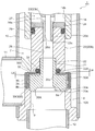
- FIG. 2 is an enlarged vertical sectional view of a main part of the electric valve shown in FIG.
- FIGS. 3 to 8 are enlarged vertical sectional views of a main part for explaining the configuration and operation of the motor-operated valve shown in FIGS.
- the gap formed between the members, the separation distance between the members, etc. are larger than the dimensions of each constituent member for easy understanding of the invention and for convenience of drawing. Or it may be drawn small.
- the motor-driven valve 1 of the illustrated embodiment is suitable for use as, for example, an expansion valve in a heat pump air conditioning system, and the fluid (refrigerant) is bidirectional (first flow direction from side to bottom and from bottom to side). In the second flow direction).
- the motor-operated valve 1 of the present embodiment includes a planetary gear speed reduction mechanism between the rotor and the screw feed mechanism so as to increase the axial force of the main valve body and improve the sealing performance. It has become.
- the motor-operated valve 1 includes a valve body 10 having a cylindrical base body 10A made of a sheet metal, a main valve body 20 disposed in the valve body 10 so as to be movable up and down, and the main valve body 20 to move up and down. And a stepping motor 50 attached to the upper side of the valve body 10.
- a valve chamber 7 is formed on the cylindrical base body 10A of the valve body 10, and a lateral first inlet / outlet (conduit joint) 11 that opens to the valve chamber 7 is attached to a side portion thereof.
- a main valve comprising a vertically oriented valve port 9 that opens from the lower side to the valve chamber 7 at the lower end of the cylindrical base body 10A (that is, the bottom of the valve chamber 7), and an inner peripheral corner of the upper end of the valve port 9.
- a stepped valve seat member 8 (a lower outer periphery of a stepped valve seat member 8b formed of an upper end outer peripheral top portion of the valve port 9 disposed outside the main valve seat 8a via a seat 8a and an inverted frustoconical surface 8c.
- a second inlet / outlet (conduit joint) 12 connected to the valve port 9 is attached to the valve seat member 8.
- a stepped cylindrical base 13 is attached to the upper surface opening of the cylindrical base body 10 ⁇ / b> A, and a cylindrical shape with a ceiling portion that constitutes a part of the stepping motor 50 is attached to the upper end of the cylindrical base 13.
- the lower end of the can 58 is hermetically joined by welding or the like.
- a cylindrical holding member 14 with a partition wall 14c is fixed to the inner peripheral side of the cylindrical base 13 by press-fitting or the like, and a bearing member provided with a female screw 15i on the lower inner periphery is provided above the cylindrical holding member 14. 15 is fixed by caulking.
- a spring chamber 14a Immediately above the partition wall 14c of the cylindrical holding member 14 is a spring chamber 14a in which a valve opening spring 25 made of a compression coil spring is accommodated.
- the main valve body 20 has a generally cylindrical shape with a step, and is a poppet valve that moves up and down in the vertical direction with respect to the main valve seat 8a to open and close the valve port 9.
- the main valve body 20 has a slightly large-diameter main valve body portion 20 ⁇ / b> A that opens and closes the valve port 9 in contact with and separates from the main valve seat 8 a of the valve seat member 8.
- a strut portion 20B having a slightly smaller diameter is provided continuously above the main valve body portion 20A, and the upper portion thereof is slidably fitted into the valve body guide hole 14b below the partition wall 14c in the cylindrical holding member 14.
- the lower half diameter fitting formed in the strut part 20B which consists of a cylindrical member is substantially upper half part of the small diameter fitting cylinder part 21 protruding upwardly at the main valve body part 20A (the upper surface center).
- the main valve body portion 20A and the strut portion 20B are integrated (that is, can move up and down integrally), and the main valve body portion 20A has a small-diameter fitting cylinder.
- a reverse frustoconical seal surface 20a that is substantially in line contact with the main valve seat 8a is provided on the outer peripheral portion of the lower surface of the main valve body 20A so as to obtain a required sealing property.
- the sub-valve body 30 for opening and closing the valve port 9 is slidable in the vertical direction on the lower outer peripheral side of the main valve body 20 (specifically, on the outer peripheral side of the main valve body portion 20A). It is arranged. That is, as described above, the main valve seat 8a in which the main valve body portion 20A (the seal surface 20a thereof) contacts and is separated from the upper inner peripheral side (corner portion) of the valve seat member 8 (valve port 9) in the valve body 10. Is provided on the upper outer peripheral side (top) of the valve seat member 8 via the inverted truncated cone surface 8c on the upper outer peripheral side (top) of the sub-valve element 30 (the lower outer flange-shaped portion 30B).
- a sub-valve seat 8b with which a lower surface (in this example, a flat surface perpendicular to the up-down direction) 30a contacts and separates is provided.
- the sub-valve body 30 has a cylindrical shape with a lower outer flange-shaped portion 30B that is inserted on the outer periphery of the lower portion of the main valve body 20 (the outer periphery of the main valve body portion 20A) so as to be movable up and down (with a predetermined gap).
- the lower outer flange-shaped portion 30B (the seal surface (the lower surface of the lower outer flange-shaped portion 30B) 30a) moves up and down in the vertical direction with respect to the sub-valve seat 8b. Open and close.
- the auxiliary valve body 30 is formed with a fitting insertion hole 30 c into which the small-diameter fitting cylinder portion 21 is slidably inserted in the ceiling portion.
- the main valve body 20 has a substantially hat-shaped cross section with a slightly larger diameter than the main valve body portion 20A. That is, the sub-valve body 30 is formed to have an outer diameter slightly larger than that of the main valve body portion 20A, and is externally inserted with a predetermined gap on the outer peripheral side of the main valve body portion 20A.
- the main valve body portion 20A has a cylindrical portion 30A with a lower outer flange-shaped portion 30B that is slightly shorter in length than the main valve body portion 20A, and has a ceiling portion (in other words, a cylindrical portion 30A) of the sub-valve body 30.
- the portion extending from the upper end to the outer periphery of the small-diameter fitting tube portion 21 of the main valve body portion 20A through the gap between the upper surface of the main valve body portion 20A and the lower surface of the strut portion 20B is the main valve body portion 20A.
- the upper inner hook-shaped hook portion 30 ⁇ / b> C is engaged with the upper surface.
- the O-ring (elastic member) 33 as a biasing member that constantly biases the sub-valve element 30 downward (in the valve closing direction) is accommodated in a compressed state (via a washer 32 described later).
- the sub-valve element 30 is slidable in the vertical direction on the main valve element 20 and is retained by being locked by the ceiling (upper inner hook-like hook part 30C).
- the valve port 9 is closed before the main valve body 20 (in other words, the seal surface 20a of the main valve body 20 is closed to the valve seat member 8 (valve port 9). )
- the dimension and shape of each part are set so that the sealing surface 30a of the sub valve body 30 is seated on the sub valve seat 8b of the valve seat member 8 (valve port 9)). (Details later).
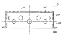
- the cylindrical portion 30A of the auxiliary valve body 30 is provided with a bleed hole 34 formed of a plurality of (or even one) through holes formed at substantially equal angular intervals, for example (see FIG. 9), a filter 35 made of a cylindrical porous body made of, for example, a sintered metal is disposed (exterior) on the outer periphery of the cylindrical portion 30A (the bleed hole 34).
- the filter 35 is formed so that the length in the vertical direction (axis O direction) is slightly longer than the cylindrical portion 30 ⁇ / b> A, and the inner end is between the sub valve body 30 and the O ring 33.
- a washer 32 made of a thin plate is disposed.
- the filter 35 mounted on the cylindrical portion 30A uses the elastic force (compression force) of the O-ring 33 to lower the upper outer flange-shaped portion 30B (the upper surface thereof) and the washer 32 (the lower surface of the outer end). Narrow pressure is maintained between.
- the filter 35 has a function of allowing refrigerant to pass but not allowing foreign matter to pass therethrough.
- the filter 35 includes a mesh member in which a wire is woven in a mesh shape, and a plurality of mesh members. It can be comprised from the laminated body laminated
- the stepping motor 50 disposed on the upper side of the valve main body 10 has a two-phase coil portion including a yoke 51, a bobbin 52, a coil 53, a resin mold 54, etc. It has a stator 55 that is externally fitted and fixed, and a rotor 57 that is rotatably arranged in a can 58 and has a rotor support member 56 fixed to the inside of the upper portion thereof. Further, on the inner peripheral side of the rotor 57, a sun gear 41 provided integrally with the rotor support member 56 and a fixing ring fixed to the tip of the cylindrical body 14d fixed to the upper end of the cylindrical holding member 14 are provided.
- a mysterious planetary gear type reduction mechanism 40 comprising an output shaft 46 and the like fixed to the gear 45 is attached.
- the number of teeth of the fixed ring gear 47 is different from the number of teeth of the output gear 45.
- the lower portion of the support shaft 49 is inserted into a hole provided in the upper portion of the output shaft 46, and the carrier 44 and the sun gear 41 (rotor support member 56) are inserted into the support shaft 49.
- a support member 48 having substantially the same diameter as the inner diameter of the can 58 is disposed, and the upper portion of the support shaft 49 is a support member. It is inserted through a hole provided at the center of 48.
- the output shaft 46 of the mysterious planetary gear speed reduction mechanism 40 is rotatably inserted into the upper portion of the bearing member 15, and the rotation of the output shaft 46 is provided on the bearing member 15 and is screwed into the screw 15 i. It is transmitted to the rotary vertical movement shaft 17 provided with the screw 17e.
- a slit-like fitting portion 46a is provided at the lower portion of the output shaft 46, and a plate-like portion 17a that is slidably fitted to the slit-like fitting portion 46a is provided on the upper portion of the rotary vertical movement shaft 17 so as to project.
- a stepped cylindrical thrust transmission member 23 is disposed below the rotary vertical movement shaft 17 and the thrust downward of the rotary vertical movement shaft 17 is transmitted through the ball 18 and the ball seat 19. . Since the ball 18 is interposed, only the downward thrust is transmitted from the rotary vertical shaft 17 to the thrust transmission member 23 even if the rotary vertical shaft 17 is lowered while rotating, and the rotational force is Not transmitted.
- the thrust transmission member 23 includes, in order from the top, a large-diameter upper portion 23a in which the ball seat 19 is fitted on the inner periphery, an intermediate body portion 23b that is slidably inserted into the partition wall 14c of the cylindrical holding member 14, A small diameter lower portion 23c having a diameter smaller than that of the intermediate body portion 23b, and a through hole 26d constituting an upper portion of a pressure equalizing passage 26 described later and a plurality of horizontal holes 26e opened in a back pressure chamber 27 described later are formed therein. Is provided. The upper end opening of the through hole 26d is closed by the ball seat 19.
- the small diameter lower portion 23c of the thrust transmission member 23 is fitted and fixed to the upper fitting hole 20d of the stepped cylindrical main valve body 20 (its strut portion 20B) by press fitting or the like, and the main valve body 20 and the thrust transmission member 23 are fixed. Can be moved up and down together.
- a pressing member 24 is sandwiched and fixed between the upper end surface of the main valve body 20 (the strut portion 20B thereof) and the lower end step portion of the intermediate body portion 23b of the thrust transmission member 23 when the small diameter lower portion 23c is press-fitted. ing.
- a sealing member 29 is mounted between the holding member 24 and the annular groove provided in the upper end portion of the main valve body 20 (the strut portion 20B) and the valve body guide hole 14b of the cylindrical holding member 14.
- a valve opening spring 25 made of a compression coil spring is mounted with its lower end in contact with the partition wall 14c.
- the lifting spring receiver 28 having a hook-like hooking portion (upper hooking portion 28a, lower hooking portion 28b) on the upper and lower sides. Is distributed.
- the upper hooking portion 28 a of the pulling spring receiving body 28 is placed on the valve opening spring 25, and the lower hooking portion 28 b is configured to hook the lower end step portion of the large-diameter upper portion 23 a of the thrust transmission member 23.
- the screw feed mechanism is constituted by the bearing member 15 provided with the female screw 15i and the rotary vertical movement shaft 17 provided with the male screw 17e.
- the stepping motor 50 rotor 57
- the rotary vertical movement shaft 17 is rotated downward, for example, by screw feed by the female screw 15i and the external screw 17e, and the thrust of the rotary vertical movement shaft 17 is rotated.
- the thrust transmission member 23 and the main valve body 20 are pushed down against the urging force of the valve opening spring 25, and finally the seal surface 20a of the main valve body portion 20A is pressed against the main valve seat 8a and the valve port 9 Is closed.
- the stepping motor 50 (rotor 57) is rotated in the other direction, for example, the rotary vertical shaft 17 is rotated while being rotated by the screw feed by the female screw 15i and the external screw 17e, and accordingly, the thrust transmission member 23 and the main valve body 20 are pulled up by the urging force of the valve opening spring 25, and the seal surface 20a of the main valve body portion 20A is lifted (raised) from the main valve seat 8a to open the valve port 9.
- a back pressure chamber 27 is defined above the main valve body 20 and between the pressing member 24 and the partition wall 14c of the cylindrical holding member 14. Further, in the main valve body 20 (the main valve body portion 20 ⁇ / b> A and the strut portion 20 ⁇ / b> B), a stepped pressure equalizing passage 26 that communicates the front end portion (lower end portion) of the main valve body 20 and the back pressure chamber 27. Is provided. The pressure equalizing passage 26 communicates with the back pressure chamber 27 together with the vertical hole 26d and the horizontal hole 26e of the thrust transmission member 23 described above.
- the diameter Da of the back pressure chamber 27 and the diameter Dc of the valve port 9 are set to be substantially the same.
- the valve closing operation is completed and the main valve body 20 and the sub-valve body 30 are located at the lowest position, that is, the main valve body 20 is seated on the main valve seat 8a.
- the O-ring 33 is pushed against the strut portion 20B of the main valve body 20 when the sub-valve body 30 is seated and pressed against the sub-valve seat 8b and is closed (when fully closed).
- a gap La is provided between the lower surface of the strut portion 20B of the main valve body 20 and the upper surface of the upper inner hook-like hook portion 30C of the sub-valve body 30 by being contracted, and the main valve body portion of the main valve body 20
- a gap Lb is provided between the upper surface of 20A and the lower surface of the upper inner hook-like hook portion 30C of the sub-valve body 30.
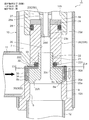
- the stepping motor 50 (rotor 57) is rotated in one direction, and the main valve body 20 is moved down with the sub-valve body 30.
- the sub valve body 30 is pushed down by the urging force (elastic force) of the O-ring 33.
- the upper inner hook-shaped hook portion 30C (the lower surface) is abutted and locked to the main valve body portion 20A (the upper surface thereof), and the lower surface of the strut portion 20B of the main valve body 20 and the upper inner hook shape of the sub-valve body 30 are A gap La + Lb is formed between the upper surface of the hook portion 30C.
- the lower end of the sub-valve element 30 (the lower outer flange-shaped part 30B) is higher than the lower end of the main valve element 20 (the main valve element part 20A).
- the coolant and the foreign substances (metal powder, shavings, abrasives, sludge, etc.) contained therein are located along the inverted truncated cone surface 8c formed at the upper end of the valve seat member 8 so that the sub-valve 30 and the auxiliary valve seat 8b and between the main valve body 20 and the main valve seat 8a.
- a foreign substance having a size (diameter) of 10 to 300 ⁇ m is assumed.
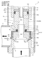
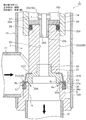
- the main valve body 20 is further moved downward from the state where the main valve body 20 shown in FIG. 3 is slightly opened and the sub-valve body 30 is slightly opened.
- the valve closing operation until the sub valve body 30 is seated on the sub valve seat 8b and closes (2), that is, the gap formed between the sub valve body 30 and the sub valve seat 8b becomes gradually smaller.
- the foreign matter contained in the refrigerant is dammed up in a minute gap formed between the sub-valve element 30 and the sub-valve seat 8b, and the part indicated by the arrow E1 in FIG.
- the small gap formed between the sub-valve body 30 and the sub-valve seat 8b accumulates on the upstream side (outer peripheral side) and becomes clogged.
- the sub-valve element 30 is seated on the sub-valve seat 8b and closed, the foreign matter is blocked by the sub-valve element 30 and is downstream (here, the main valve body 20 and the main valve seat 8a on the inner peripheral side). Will not flow.
- a part of the refrigerant Is a filter 35 provided on the outer periphery of the sub-valve body 30, a bleed hole 34 provided in the sub-valve body 30, between the sub-valve body 30 (the inner circumference) and the main valve body 20 (the outer circumference).
- the seal surface 20a of the main valve body 20 is seated on the main valve seat 8a and closed as shown in FIG.
- the refrigerant stops flowing (the flow rate becomes 0).
- the main valve body 20 is strongly pressed against the main valve seat 8a by a high axial force by the mysterious planetary gear speed reduction mechanism 40.
- the O-ring 33 is compressed by the strut portion 20B of the main valve body 20 by the gap Lb, so that the lower surface of the strut portion 20B of the main valve body 20 and the upper inner hook shape of the sub-valve body 30 are formed.
- the gap formed between the upper surface of the hook portion 30C is only La to Lb, and the upper surface of the main valve body portion 20A of the main valve body 20 and the lower surface of the upper inner hook-like hook portion 30C of the sub-valve body 30 In the meantime, the gap Lb is opened, and the auxiliary valve body 30 is pressed against the auxiliary valve seat 8b by the urging force (elastic force) of the O-ring 33.
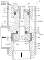
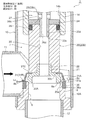
- the stepping motor 50 (rotor 57) is rotated in the other direction, and thereby the main valve body 20 is pulled up as shown in FIG.
- the main valve body 20 is slightly opened from the closed state, whereby the main valve body of the main valve body 20 is urged by the urging force (elastic force) of the O-ring 33.
- the lower surface of the upper inner hook-like hook portion 30C of the sub-valve body 30 is abutted and locked to the upper surface of the portion 20A, and the lower surface of the strut portion 20B of the main valve body 20 and the upper inner hook-like hook portion of the sub-valve body 30
- the gap formed between the upper surface of 30C is changed from La to La + Lb, and the auxiliary valve body 30 remains closed, but the pressing force by the O-ring (elastic member) 33 is reduced.
- a part of the refrigerant (a minute flow rate) is a filter 35 provided on the outer periphery of the sub-valve element 30 and a bleed provided on the sub-valve element 30. It flows out to the valve port 9 side through the hole 34, the gap between the sub-valve body 30 (the inner circumference) and the main valve body 20 (the outer circumference), between the main valve body 20 and the main valve seat 8a. Become. Therefore, the balance between the push-down force (force acting in the valve closing direction) acting on the sub-valve body 30 and the push-up force (force acting in the valve opening direction) acting on the sub-valve body 30 in the valve-closed state is canceled. Thus, the push-down force acting on the closed valve body 30 is further reduced.
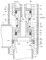
- FIGS. 7 and 8 states corresponding to FIGS. 3 and 4 at the time of the second flow from the bottom to the side.
- the main valve body 20 is moved downward from the state where the main valve body 20 is slightly opened and the sub-valve body 30 is slightly opened, and is formed between the sub-valve body 30 and the sub-valve seat 8b.
- the gap becomes gradually smaller and finally becomes 0, the foreign matter contained in the refrigerant is blocked by a minute gap formed between the sub-valve body 30 and the sub-valve seat 8b.
- a part of the refrigerant (a minute flow rate) is a gap between the main valve body 20 and the main valve seat 8a, a gap between the sub valve body 30 (the inner circumference) and the main valve body 20 (the outer circumference), a sub-flow Since it flows out to the valve chamber 7 side through the bleed hole 34 provided in the valve body 30 and the filter 35 provided on the outer periphery of the sub-valve body 30, the push-down force acting on the sub-valve body 30 (force acting in the valve closing direction) ) And the pushing-up force (force acting in the valve opening direction) acting on the sub-valve body 30 is balanced (differential pressure is canceled), and foreign matter is clogged in the gap between the main valve body 20 and the main valve seat 8a. There is nothing.
- the main valve body 20 is further lowered from the slightly opened state shown in FIG. 8, the main valve body 20 is seated on the main valve seat 8a and is closed, and the refrigerant does not flow.
- the O-ring 33 is compressed by the strut portion 20B of the main valve body 20 by the gap Lb, so that the lower surface of the strut portion 20B of the main valve body 20 and the upper inner hook shape of the sub-valve body 30 are formed.
- the gap formed between the upper surface of the hook portion 30C is only La to Lb, and the upper surface of the main valve body portion 20A of the main valve body 20 and the lower surface of the upper inner hook-like hook portion 30C of the sub-valve body 30 In the meantime, the gap Lb is opened, and the auxiliary valve body 30 is pressed against the auxiliary valve seat 8 b by the urging force (elastic force) of the O-ring (elastic member) 33.
- the auxiliary valve body 30 that closes the valve port 9 before the main valve body 20 is provided on the outer periphery of the main valve body 20.
- the fluid refrigerant
- the sub-valve body 30 is closed from there, the fluid (refrigerant) does not substantially flow.
- Foreign matter is not caught between the main valve body 20 and the main valve seat 8a. Therefore, even if the main valve body 20 is closed and strongly pressed against the main valve seat 8a, the main valve body 20 and the main valve seat 8a are not damaged or dented.
- the rotor 57 and the screw feed mechanism (the bearing member 15 provided with the female screw 15i, A strange planetary gear speed reduction mechanism 40 is interposed between the rotary vertical movement shaft 17) provided with the male screw 17e, and the axial force of the main valve body 20, that is, the main valve body 20 is applied to the main valve seat 8a.
- the pressing force is increased, it is difficult to cause a situation in which foreign matter contained in the fluid (refrigerant) is caught between the main valve body 20 and the main valve seat 8a and strongly pressed against them.
- the main valve seat 8a, the sub-valve seat 8b, the main valve body 20, and the sub-valve body 30 can be prevented from being scratched or dented. As a result, the valve leakage is effectively prevented and the valve is closed. Reliability can be improved.
- the sub valve body 30 closes the valve port 9 on the outer periphery of the sub valve body 30, until the main valve body 20 closes the valve port 9 (in other words, for example, after the main valve body 20 opens the valve port 9 and the sub-valve body 30 closes the valve port 9), a filter 35 that connects the valve port 9 and the valve chamber 7 is provided. Therefore, the fluid (refrigerant) passes through the filter 35 when the valve is opened. Therefore, the differential pressure acting on the sub-valve body 30 can be canceled, and foreign matter contained in the passing fluid (refrigerant) is captured by the filter 35, and the foreign matter contained in the fluid (refrigerant) is separated from the main valve body 20. It is difficult to cause a situation where the main valve seat 8a is caught between the main valve seats 8a and strongly pressed against them.
- the filter 35 for allowing the fluid (refrigerant) to pass through and trapping foreign matter contained in the fluid (refrigerant) is disposed outside the subvalve body 30 (the cylindrical portion 30A). However, for example, it may of course be arranged on the inner side (inner circumference) of the auxiliary valve body 30 (the cylindrical portion 30A). Further, the filter 35 is held and fixed to the sub-valve body 30 by using the washer 32, but needless to say that the method for holding and fixing the filter 35 is not limited to the above-described form.
- FIG. 10 to FIG. 13 are enlarged vertical sectional views of the essential parts for explaining the configuration and operation of the second embodiment of the motor-operated valve according to the present invention.
- the motor-operated valve 2 of the illustrated second embodiment has substantially the same configuration as the motor-operated valve 1 of the first embodiment shown in FIGS. 1 to 9 except for the main valve body, the sub-valve body, and the periphery of the valve port. .
- portions corresponding to the respective portions of the motor-operated valve 1 of the first embodiment and portions having similar functions are denoted by common reference numerals and redundant description is omitted, and the following description will focus on the differences.
- valve seat member 8 fixed to the lower end portion of the cylindrical base body 10A (that is, the bottom portion of the valve chamber 7) has a vertical valve port 9 that opens from the lower side to the valve chamber 7, and the valve port 9
- a main valve seat 8a composed of an inner peripheral corner of the upper end is formed, and a ring having a rectangular cross section made of, for example, sintered metal is formed on an outer peripheral step portion 36a formed on the outer side of the main valve seat 8a in the valve port 9.
- a filter 36 made of a porous material is fitted and fixed by press-fitting or the like, and the upper surface of the filter 36 is brought into contact with and separated from the subvalve element 31 (the seal surface (the lower surface of the lower outer flange-shaped portion 31B) 31a).
- the auxiliary valve seat 8b is used.
- a sub-valve body 31 for opening and closing the valve port 9 is disposed on the lower outer peripheral side of the main valve body 20 (specifically, on the outer peripheral side of the main valve body portion 20A).
- This sub-valve element 31 includes a truncated cone-shaped part 31A with a lower outer flange-shaped part 31B that is extrapolated (with a predetermined gap) on the lower outer periphery of the main valve body 20 (the outer periphery of the main valve body part 20A).
- the lower outer flange-shaped portion 31B (the seal surface (the lower surface of the lower outer flange-shaped portion 31B) 31a) moves up and down in the vertical direction with respect to the auxiliary valve seat 8b provided in the filter 36.
- the valve port 9 is opened and closed.
- the sub-valve element 31 is made of, for example, a SUS304CSP-3 / 4H material and is made of a spring plate material that has been subjected to annealing for removing stress (in other words, elastically deformable). Has been.
- the sub-valve body 31 has an outer diameter slightly larger than that of the main valve body portion 20A.
- the sub-valve body 31 is extrapolated with a predetermined gap on the outer peripheral side of the main valve body portion 20A, and has a length in the vertical direction (axis O direction).
- 31C is narrowly held and fixed between the main valve body portion 20A (the upper surface outer periphery thereof) and the strut portion 20B (the lower surface outer periphery thereof) of the main valve body 20.
- the sub-valve body 31 itself is made of an elastic spring plate material, and an urging member (such as an O-ring) that constantly urges the sub-valve body 31 downward (in the valve closing direction) Omitted, the sub-valve element 31 (the lower outer flange-shaped part 31B) is always urged downward (in the valve-closing direction) by the elastic force (elastic repulsive force) of the sub-valve element 31.
- an urging member such as an O-ring
- the sub valve body 31 closes the valve port 9 before the main valve body 20 when the main valve body 20 is closed from the open state.
- the seal surface 30a of the sub valve body 30 is The size and shape of each part are set so as to be seated on the secondary valve seat 8b of the valve port 9) (details will be described later).
- the sub-valve body 31 (the lower outer flange portion 31 ⁇ / b> B) is elastically seated on the valve port 9 outside the main valve seat 8 a.
- a fluid (refrigerant) flows between the valve chamber 7 and the valve port 9 through the filter 36 and the main valve body 20 (the main valve body portion 20A) and the main valve seat 8a (details will be described later).
- the valve closing operation is completed and the main valve body 20 and the sub-valve body 31 are positioned at the lowest position, that is, the main valve body 20 is seated on the main valve seat 8a and pressed.
- the sub-valve element 31 is seated and pressed against the sub-valve seat 8b and both are closed (when fully closed), the sub-valve element 31 is elastically deformed, and its lower outer flange-shaped portion 31B is pushed upward by a displacement Lc from the natural state (also referred to as a no-load state).
- the stepping motor 50 (rotor 57) is rotated in one direction, and the main valve body 20 is lowered with the sub-valve body 31.
- the sub-valve element 31 is in an unloaded state, so that the lower outer flange-shaped part 31B is moved by the elastic restoring force (elastic repulsive force) of the sub-valve element 31 itself. Pressed down.
- the lower end of the sub-valve element 31 (the lower outer flange-shaped part 31B) is higher than the lower end of the main valve element 20 (the main valve element portion 20A).
- the coolant and the foreign substances (metal powder, shavings, abrasives, sludge, etc.) contained therein are located along the inverted truncated cone surface 8c formed at the upper end of the valve seat member 8 so that the sub-valve 31 and the auxiliary valve seat 8b and between the main valve body 20 and the main valve seat 8a.
- the main valve body 20 is further moved down as shown in FIG.
- the gap formed between the sub valve body 31 and the sub valve seat 8b becomes gradually smaller.
- the foreign matter contained in the refrigerant is dammed up in a minute gap formed between the sub-valve element 31 and the sub-valve seat 8b, and the part indicated by the arrow E1 in FIG.
- the small gap formed between the sub valve body 31 and the sub valve seat 8b accumulates on the upstream side (outer peripheral side) and becomes clogged.
- the seal surface 20a of the main valve body 20 is seated on the main valve seat 8a and closed as shown in FIG.
- the refrigerant stops flowing (the flow rate becomes 0).
- the main valve body 20 is strongly pressed against the main valve seat 8a by a high axial force by the mysterious planetary gear speed reduction mechanism 40.
- the sub-valve element 31 is elastically deformed (along with the downward movement of the main valve element 20), and the lower outer flange-shaped portion 31B is pushed upward by a displacement amount Lc from the natural state.
- the valve body 31 (the lower outer flange portion 31B) is pressed against the auxiliary valve seat 8b by the elastic force of the auxiliary valve body 31 itself.
- the stepping motor 50 (rotor 57) is rotated in the other direction, whereby the main valve body 20 is pulled up and opened as shown in FIG. I speak.
- the sub-valve body 31 (the lower outer flange portion 31B) is closed by the elastic restoring force (elastic repulsive force) of the sub-valve body 31 itself.
- the pressing force due to the elastic force of the sub-valve element 31 itself is small.
- a part of the refrigerant (a minute flow rate) is a filter 36 having a sub-valve seat 8 b provided on the outer peripheral portion of the valve port 9, and the main valve body. It flows out to the valve port 9 side through between 20 and the main valve seat 8a. Therefore, the balance between the push-down force (force acting in the valve closing direction) acting on the sub-valve body 31 and the push-up force (force acting in the valve opening direction) acting on the sub-valve body 31 in the valve closing state is balanced (the differential pressure is canceled). Thus, the push-down force acting on the closed sub valve body 31 is further reduced.
- an elastically deformable sub-valve body 31 that closes the valve port 9 before the main valve body 20 is provided on the outer periphery of the main valve body 20. Therefore, when the sub-valve element 31 is in the slightly opened state, foreign matter contained in the fluid (refrigerant) is blocked by the sub-valve element 31, and when the sub-valve element 31 is closed from there, the fluid (refrigerant) is substantially Therefore, the foreign matter is not caught between the main valve body 20 and the main valve seat 8a. Therefore, even if the main valve body 20 is closed and strongly pressed against the main valve seat 8a, the main valve body 20 and the main valve seat 8a are not damaged or dented.
- the foreign matter contained in the fluid is caught between the main valve body 20 and the main valve seat 8a and strongly resists them.
- the main valve seat 8a, the sub-valve seat 8b, the main valve body 20, and the sub-valve body 31 can be prevented from being scratched or dented, resulting in valve leakage. It can prevent effectively and can improve the reliability of valve closing.
- the number of parts can be reduced and the parts configuration can be simplified.
- the urging member (O-ring or the like) that constantly urges the sub-valve element 31 downward (in the valve closing direction) is omitted, but for example, FIG. 1 to FIG.
- an O-ring elastic member
- an elastic member such as reference
- a seal member 39 made of an O-ring or ring-shaped packing may be attached.
- the mysterious planet is placed between the rotor 57 and the screw feed mechanism in order to strongly press the main valve body 20 against the main valve seat 8a (in other words, improve the sealing performance).
- the gear speed reduction type with the gear type speed reduction mechanism 40 interposed is described as an example, the present invention is a linear motion type (detailed structure and structure) with the mysterious planetary gear type speed reduction mechanism 40 and related parts removed.
- the description of the operation can be applied to the above-mentioned Patent Document 1 if necessary.
- the motor-operated valve according to the present invention is not limited to the configuration of each of the above-described embodiments.
- the configuration around the main valve body and the sub-valve body can be variously changed.
Landscapes
- Engineering & Computer Science (AREA)
- General Engineering & Computer Science (AREA)
- Mechanical Engineering (AREA)
- Electrically Driven Valve-Operating Means (AREA)
- Details Of Valves (AREA)
- Lift Valve (AREA)
Applications Claiming Priority (2)
| Application Number | Priority Date | Filing Date | Title |
|---|---|---|---|
| JP2018-107480 | 2018-06-05 | ||
| JP2018107480A JP7044246B2 (ja) | 2018-06-05 | 2018-06-05 | 電動弁 |
Publications (1)
| Publication Number | Publication Date |
|---|---|
| WO2019235149A1 true WO2019235149A1 (ja) | 2019-12-12 |
Family
ID=68770187
Family Applications (1)
| Application Number | Title | Priority Date | Filing Date |
|---|---|---|---|
| PCT/JP2019/019207 Ceased WO2019235149A1 (ja) | 2018-06-05 | 2019-05-15 | 電動弁 |
Country Status (2)
| Country | Link |
|---|---|
| JP (2) | JP7044246B2 (enExample) |
| WO (1) | WO2019235149A1 (enExample) |
Cited By (1)
| Publication number | Priority date | Publication date | Assignee | Title |
|---|---|---|---|---|
| JP2023155785A (ja) * | 2022-04-11 | 2023-10-23 | 株式会社不二工機 | 電動弁 |
Families Citing this family (3)
| Publication number | Priority date | Publication date | Assignee | Title |
|---|---|---|---|---|
| JP7361628B2 (ja) * | 2020-02-19 | 2023-10-16 | 株式会社鷺宮製作所 | 電動弁及び冷凍サイクルシステム |
| JP7519265B2 (ja) * | 2020-10-26 | 2024-07-19 | 株式会社鷺宮製作所 | 電動弁および冷凍サイクルシステム |
| JP2025101953A (ja) * | 2023-12-26 | 2025-07-08 | 株式会社不二工機 | 電動弁 |
Citations (2)
| Publication number | Priority date | Publication date | Assignee | Title |
|---|---|---|---|---|
| JP2000120886A (ja) * | 1998-10-09 | 2000-04-28 | Mitsubishi Heavy Ind Ltd | 高温隔離弁 |
| JP2013130271A (ja) * | 2011-12-22 | 2013-07-04 | Fuji Koki Corp | 電動弁 |
Family Cites Families (8)
| Publication number | Priority date | Publication date | Assignee | Title |
|---|---|---|---|---|
| JPS4413244Y1 (enExample) * | 1965-02-26 | 1969-06-02 | ||
| JPS58101057U (ja) * | 1981-12-29 | 1983-07-09 | 株式会社ノーリツ | 電磁弁 |
| JP4465122B2 (ja) | 2001-01-15 | 2010-05-19 | パナソニック株式会社 | 空気調和機 |
| JP4535308B2 (ja) | 2001-02-07 | 2010-09-01 | パナソニック株式会社 | 空気調和機 |
| JP5956749B2 (ja) * | 2011-12-21 | 2016-07-27 | キヤノン株式会社 | 防振制御装置及びその制御方法、及び撮像装置 |
| JP5380562B2 (ja) | 2012-02-14 | 2014-01-08 | 株式会社不二工機 | 電動弁 |
| JP6768297B2 (ja) | 2016-01-20 | 2020-10-14 | 株式会社不二工機 | 流量調整弁 |
| JP6692215B2 (ja) | 2016-05-26 | 2020-05-13 | 株式会社不二工機 | 流量調整弁 |
-
2018
- 2018-06-05 JP JP2018107480A patent/JP7044246B2/ja active Active
-
2019
- 2019-05-15 WO PCT/JP2019/019207 patent/WO2019235149A1/ja not_active Ceased
-
2022
- 2022-03-04 JP JP2022033125A patent/JP7333976B2/ja active Active
Patent Citations (2)
| Publication number | Priority date | Publication date | Assignee | Title |
|---|---|---|---|---|
| JP2000120886A (ja) * | 1998-10-09 | 2000-04-28 | Mitsubishi Heavy Ind Ltd | 高温隔離弁 |
| JP2013130271A (ja) * | 2011-12-22 | 2013-07-04 | Fuji Koki Corp | 電動弁 |
Cited By (2)
| Publication number | Priority date | Publication date | Assignee | Title |
|---|---|---|---|---|
| JP2023155785A (ja) * | 2022-04-11 | 2023-10-23 | 株式会社不二工機 | 電動弁 |
| JP7550466B2 (ja) | 2022-04-11 | 2024-09-13 | 株式会社不二工機 | 電動弁 |
Also Published As
| Publication number | Publication date |
|---|---|
| JP2019211006A (ja) | 2019-12-12 |
| JP7333976B2 (ja) | 2023-08-28 |
| JP7044246B2 (ja) | 2022-03-30 |
| JP2022071144A (ja) | 2022-05-13 |
Similar Documents
| Publication | Publication Date | Title |
|---|---|---|
| JP7333976B2 (ja) | 電動弁 | |
| WO2019163319A1 (ja) | 電動弁 | |
| JP5901960B2 (ja) | 電動弁 | |
| JP5055013B2 (ja) | 電動弁 | |
| CN110500424B (zh) | 三通切换阀 | |
| JP5597468B2 (ja) | エアオペレートバルブ | |
| CN106168304B (zh) | 电动阀 | |
| JP2012172749A (ja) | バルブ装置 | |
| JP2000227165A (ja) | 電動式コントロールバルブ | |
| JP7519265B2 (ja) | 電動弁および冷凍サイクルシステム | |
| CN108071839A (zh) | 电动阀以及使用了该电动阀的冷冻循环系统 | |
| JP2019060479A (ja) | 電動弁 | |
| JP2012241877A (ja) | バルブ装置 | |
| EP1724402A1 (en) | Self-sealing floor drainage | |
| JP5380562B2 (ja) | 電動弁 | |
| CN214743672U (zh) | 电动阀以及冷冻循环系统 | |
| JP6507068B2 (ja) | 電動弁及びその組立方法 | |
| JP2010223384A (ja) | 可逆式電動弁 | |
| JP7550466B2 (ja) | 電動弁 | |
| KR101969578B1 (ko) | 선택가능한 포트를 갖는 체크밸브 겸용 전자팽창밸브 및 냉난방 시스템 | |
| JP5911706B2 (ja) | 電動弁 | |
| US20060124182A1 (en) | Angled fluid control valve seal | |
| JP7550465B2 (ja) | 電動弁 | |
| CN111022661A (zh) | 一种密闭阀及核工业厂房 | |
| JP2011196362A (ja) | フィルタの取付け構造 |
Legal Events
| Date | Code | Title | Description |
|---|---|---|---|
| 121 | Ep: the epo has been informed by wipo that ep was designated in this application |
Ref document number: 19815542 Country of ref document: EP Kind code of ref document: A1 |
|
| NENP | Non-entry into the national phase |
Ref country code: DE |
|
| 122 | Ep: pct application non-entry in european phase |
Ref document number: 19815542 Country of ref document: EP Kind code of ref document: A1 |