WO2019234902A1 - 空気調和装置の室内機及び空気調和装置 - Google Patents
空気調和装置の室内機及び空気調和装置 Download PDFInfo
- Publication number
- WO2019234902A1 WO2019234902A1 PCT/JP2018/021963 JP2018021963W WO2019234902A1 WO 2019234902 A1 WO2019234902 A1 WO 2019234902A1 JP 2018021963 W JP2018021963 W JP 2018021963W WO 2019234902 A1 WO2019234902 A1 WO 2019234902A1
- Authority
- WO
- WIPO (PCT)
- Prior art keywords
- refrigerant
- sensitivity sensor
- sensor
- indoor unit
- air
- Prior art date
Links
Images


Classifications
-
- F—MECHANICAL ENGINEERING; LIGHTING; HEATING; WEAPONS; BLASTING
- F24—HEATING; RANGES; VENTILATING
- F24F—AIR-CONDITIONING; AIR-HUMIDIFICATION; VENTILATION; USE OF AIR CURRENTS FOR SCREENING
- F24F11/00—Control or safety arrangements
- F24F11/30—Control or safety arrangements for purposes related to the operation of the system, e.g. for safety or monitoring
- F24F11/32—Responding to malfunctions or emergencies
- F24F11/36—Responding to malfunctions or emergencies to leakage of heat-exchange fluid
-
- F—MECHANICAL ENGINEERING; LIGHTING; HEATING; WEAPONS; BLASTING
- F24—HEATING; RANGES; VENTILATING
- F24F—AIR-CONDITIONING; AIR-HUMIDIFICATION; VENTILATION; USE OF AIR CURRENTS FOR SCREENING
- F24F13/00—Details common to, or for air-conditioning, air-humidification, ventilation or use of air currents for screening
- F24F13/20—Casings or covers
-
- F—MECHANICAL ENGINEERING; LIGHTING; HEATING; WEAPONS; BLASTING
- F25—REFRIGERATION OR COOLING; COMBINED HEATING AND REFRIGERATION SYSTEMS; HEAT PUMP SYSTEMS; MANUFACTURE OR STORAGE OF ICE; LIQUEFACTION SOLIDIFICATION OF GASES
- F25B—REFRIGERATION MACHINES, PLANTS OR SYSTEMS; COMBINED HEATING AND REFRIGERATION SYSTEMS; HEAT PUMP SYSTEMS
- F25B49/00—Arrangement or mounting of control or safety devices
- F25B49/02—Arrangement or mounting of control or safety devices for compression type machines, plants or systems
Definitions
- the present invention relates to an indoor unit and an air conditioner of an air conditioner including a sensor that detects a refrigerant leaked from a refrigerant pipe.
- Patent Document 1 discloses a technique for determining whether or not refrigerant leaked into an indoor space is being stirred.
- the sensitivity threshold is decreased by increasing the alarm threshold of the refrigerant leakage sensor.
- the notification threshold value of the refrigerant leakage sensor is lowered to increase the sensitivity. Thereby, the detection of the refrigerant is promoted.
- Patent Document 2 discloses a technique in which a plurality of refrigerant leakage sensors are installed at the outlet in a casing.
- the sensitivity of the sensor is increased by lowering the notification threshold during operation of the blower, and the sensitivity of the sensor is decreased by increasing the notification threshold when the blower is stopped.
- Patent Document 2 a refrigerant leakage sensor is installed at the outlet, and the sensitivity of the refrigerant leakage sensor during operation of the blower is set higher than when stopped.
- Patent Document 1 the sensitivity of the refrigerant leakage sensor during operation of the blower is set lower than that at the time of stopping.
- a refrigerant leak sensor is arranged at the outlet in the casing of the indoor unit.
- the refrigerant leaked in the casing of the indoor unit is agitated during operation of the blower until it reaches the outlet.
- the stirred refrigerant is mixed with air to reduce the refrigerant concentration, making it difficult to detect refrigerant leakage.
- it is difficult to detect refrigerant leakage if there is no refrigerant leakage sensor in the flow path where the concentration of the stirred refrigerant is high.
- This invention is for solving the said subject, and it aims at providing the indoor unit and air conditioning apparatus of an air conditioning apparatus which can detect a refrigerant
- An indoor unit of an air conditioner according to the present invention includes a high-sensitivity sensor that detects refrigerant leaked from a refrigerant pipe, and a low-sensitivity sensor that detects refrigerant leaked from the refrigerant pipe with lower sensitivity than the high-sensitivity sensor.
- the high-sensitivity sensor is arranged at an air inlet.
- An air conditioner according to the present invention includes the indoor unit of the air conditioner described above.
- the high sensitivity sensor is arranged at the air inlet. For this reason, when the leaked refrigerant mixed with the room air after being blown out from the indoor unit is sucked from the suction port, the refrigerant leakage can be quickly detected by the high sensitivity sensor. Thereby, the refrigerant concentration in the indoor space mixed with the refrigerant can be prevented from exceeding a certain lower limit ignition concentration. Further, since the low sensitivity sensor is provided separately from the high sensitivity sensor, refrigerant leakage can be reliably detected even if one of the two sensors fails. Therefore, refrigerant leakage can be reliably detected not only when the blower is stopped but also during operation.
- 3 is a cross-sectional view showing the indoor unit of the air-conditioning apparatus according to Embodiment 1 of the present invention, taken along the line XX in FIG. It is explanatory drawing which shows the indoor unit of the air conditioning apparatus which concerns on Embodiment 1 of this invention in the state which attached the sensor holder to the electrical component box. It is a front view which shows the 1st sensor holder which concerns on Embodiment 1 of this invention.
- FIG. 1 is a refrigerant circuit diagram showing an air-conditioning apparatus 100 according to Embodiment 1 of the present invention.
- an outdoor unit 101 and an indoor unit 102 are connected by a gas refrigerant pipe 103 and a liquid refrigerant pipe 104.
- the outdoor unit 101 includes a compressor 105, a four-way valve 106, an outdoor heat exchanger 107, an expansion valve 108, and a blower 109.
- Compressor 105 compresses and discharges the sucked refrigerant.
- the compressor 105 may change an operation frequency arbitrarily, for example with an inverter circuit etc., and may change the capacity
- FIG. 1
- the four-way valve 106 is a valve that switches the flow of the refrigerant between, for example, a cooling operation and a heating operation.
- the outdoor heat exchanger 107 performs heat exchange between the refrigerant and the outdoor air.
- the outdoor heat exchanger 107 functions as a condenser during the cooling operation, and condenses and liquefies the refrigerant.
- the outdoor heat exchanger 107 functions as an evaporator during heating operation, and evaporates and evaporates the refrigerant.
- the expansion valve 108 is a flow control valve, and decompresses the refrigerant to expand it.
- the expansion valve 108 is constituted by an electronic expansion valve, for example, the opening degree can be adjusted based on an instruction from the control unit 110.
- the blower 109 blows outside air to the outdoor heat exchanger 107 and promotes heat exchange of the outdoor heat exchanger 107.
- the outdoor unit 101 includes a control unit 110.
- the control unit 110 communicates with the determination unit 5 of the indoor unit 102 described later and performs various controls.
- the indoor unit 102 includes an indoor heat exchanger 1 and a blower 2.
- the indoor heat exchanger 1 performs heat exchange between air to be air-conditioned and a refrigerant, for example.
- the indoor heat exchanger 1 functions as an evaporator during the cooling operation, and evaporates and evaporates the refrigerant.
- the indoor heat exchanger 1 functions as a condenser during heating operation, and condenses and liquefies the refrigerant.
- the blower 2 blows indoor air to the indoor heat exchanger 1 and promotes heat exchange of the indoor heat exchanger 1.
- the refrigerant flow is switched by the four-way valve 106 of the outdoor unit 101, and the cooling operation or the heating operation can be realized.
- the indoor unit 102 includes a high sensitivity sensor 3, a low sensitivity sensor 4, and a determination unit 5.
- the high sensitivity sensor 3 detects refrigerant leaking from the refrigerant pipe in the indoor unit 102.
- the low sensitivity sensor 4 detects the refrigerant leaked from the refrigerant pipe in the indoor unit 102 with a sensitivity lower than that of the high sensitivity sensor 3.
- the refrigerant pipes are all pipes through which the refrigerant flows including the gas refrigerant pipe 103, the liquid refrigerant pipe 104, and the heat transfer pipe of the indoor heat exchanger 1.
- the determination unit 5 determines refrigerant leakage based on the detection information of the high sensitivity sensor 3 and the low sensitivity sensor 4.
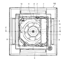
- FIG. 2 is a bottom view showing the indoor unit 102 of the air-conditioning apparatus 100 according to Embodiment 1 of the present invention with the suction grill removed.
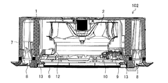
- FIG. 3 is a cross-sectional view showing the indoor unit 102 of the air-conditioning apparatus 100 according to Embodiment 1 of the present invention, taken along the line XX of FIG.
- FIG. 4 is an explanatory diagram showing the indoor unit 102 of the air-conditioning apparatus 100 according to Embodiment 1 of the present invention with the first and second sensor holders 10 and 11 attached to the electrical component box 9.
- the suction port 6 is formed in the central portion of the housing 7, and the blowout ports 8 for blowing conditioned air are formed on the four sides around the suction port 6. It is a ceiling-embedded indoor unit.
- the indoor unit 102 includes an electrical component box 9, a first sensor holder 10, a second sensor holder 11, a bell mouth 12, a drain pan 13, an indoor heat exchanger 1, and a blower 2 in a housing 7 from which a suction grill is removed. doing.
- a determination unit 5 is configured in the electrical component box 9, a determination unit 5 is configured.
- the electrical component box 9 is installed facing a suction side air passage that extends from the suction port 6 to the back.
- Two first and second sensor holders 10 and 11 are attached to the surface portion of the electrical component box 9 so as to face the suction port 6.
- the first sensor holder 10 is attached to the surface portion of the electrical component box 9 and incorporates the high sensitivity sensor 3 and the suction temperature sensor 14. Thereby, the high sensitivity sensor 3 is arrange
- the second sensor holder 11 is parallel to the first sensor holder 10 in the horizontal direction, is attached to the surface portion of the electrical component box 9, and incorporates the low sensitivity sensor 4.
- the second sensor holder 11 has no built-in suction temperature sensor. Thereby, the low sensitivity sensor 4 is arrange
- the position where the first and second sensor holders 10 and 11 are attached is a position below the indoor heat exchanger 1. Thereby, the low sensitivity sensor 4 is arrange
- the high sensitivity sensor 3 and the low sensitivity sensor 4 output analog output signals. For this reason, when a communication line such as a lead wire connected from the high sensitivity sensor 3 and the low sensitivity sensor 4 to the determination unit 5 runs in parallel with the power supply line or the blower 2, there is a concern that noise is added to the sensor output signal. On the other hand, when the first and second sensor holders 10 and 11 are directly installed in the electrical component box 9, the communication line is shortened and the adverse effect of noise is prevented.
- the high-sensitivity sensor 3 and the low-sensitivity sensor 4 are located in the vicinity of the suction port 6 so that the high-sensitivity sensor 3 or the low-sensitivity sensor 4 can detect when the refrigerant concentration of the indoor air becomes high within the range of the ignition lower limit concentration. Is installed.
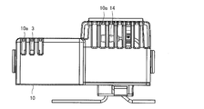
- FIG. 5 is a front view showing the first sensor holder 10 according to Embodiment 1 of the present invention.
- FIG. 6 is a left side view showing the first sensor holder 10 according to Embodiment 1 of the present invention.
- FIG. 7 is a right side view showing the first sensor holder 10 according to Embodiment 1 of the present invention.
- FIG. 8 is an internal development view showing the first sensor holder 10 according to Embodiment 1 of the present invention.
- the high sensitivity sensor 3 is built in the first sensor holder 10 together with the suction temperature sensor 14.
- a plurality of slits 10 a are formed in the first sensor holder 10 so that the high-sensitivity sensor 3 and the suction temperature sensor 14 directly come into the suction air.
- the high-sensitivity sensor 3 is configured mainly using a semiconductor sensitive gas element, and outputs due to the oxygen concentration.
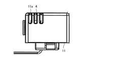
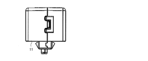
- FIG. 9 is a front view showing the second sensor holder 11 according to Embodiment 1 of the present invention.
- FIG. 10 is a left side view showing the second sensor holder 11 according to Embodiment 1 of the present invention.
- FIG. 11 is a right side view showing the second sensor holder 11 according to Embodiment 1 of the present invention.
- the low sensitivity sensor 4 is built in the second sensor holder 11.
- a plurality of slits 11 a are formed in the second sensor holder 11 so that the low-sensitivity sensor 4 directly receives the suction air.
- the low-sensitivity sensor 4 is configured mainly using a semiconductor sensitive gas element, and outputs due to the oxygen concentration.
- the low-sensitivity sensor 4 is output due to an oxygen concentration lower than that of the high-sensitivity sensor 3 from the beginning of manufacture, and detects the refrigerant with lower sensitivity than the high-sensitivity sensor 3.
- FIG. 12 is a block diagram showing an electrical component box 9 constituting the determination unit 5 according to Embodiment 1 of the present invention.
- the determination unit 5 is a processing circuit having a microcomputer including a CPU, a memory such as a ROM and a RAM, and an input / output device such as an I / O port.
- the control unit 110 mounted on the outdoor unit 101 has a processing circuit similar to that of the determination unit 5.
- the determination unit 5 detects the refrigerant leaked by the low sensitivity sensor 4 at all times or periodically regardless of whether the blower 2 is operated or stopped.
- the determination unit 5 detects the refrigerant leaked by the high sensitivity sensor 3 during operation of the blower 2.
- the determination unit 5 stops the detection of the high sensitivity sensor 3 when the blower 2 is stopped.
- the determination unit 5 transmits detection information to the control unit 110 of the outdoor unit 101 when the high sensitivity sensor 3 or the low sensitivity sensor 4 detects the leakage of the refrigerant.
- the control unit 110 of the outdoor unit 101 performs protection control such as pumping down so as to close an on-off valve in the refrigerant circuit and prevent the refrigerant from being supplied to the indoor unit 102.
- FIG. 13 is a diagram illustrating the detection timing for the leakage refrigerant concentration of the high-sensitivity sensor 3 and the low-sensitivity sensor 4 according to Embodiment 1 of the present invention.
- the vertical axis indicates the leakage refrigerant concentration in the indoor air.
- the horizontal axis is a time axis.
- the detection timing basically shows a proportional characteristic that rises to the right.
- the first detection point of the high sensitivity sensor 3 is a point when the leakage refrigerant concentration is the first threshold value.
- the first threshold value is a value at which erroneous detection by the high-sensitivity sensor 3 is issued when the blower 2 is stopped, for example, due to a decrease in oxygen concentration when the user sprays the pest control agent in the indoor space.
- the first threshold is the same component as the refrigerant that leaked when the blower 2 is stopped, for example, when the user sprays the deodorizing spray containing the same component as the refrigerant such as propane on the indoor space or the indoor unit 102. This is a value at which erroneous detection by the high-sensitivity sensor 3 due to the detection of is issued.
- the first threshold value is a value that is highly sensitive enough to be erroneously detected on a daily basis when the blower 2 is stopped.
- the second detection point of the low sensitivity sensor 4 is a point when the leaked refrigerant concentration is a second threshold value having a concentration higher than the first threshold value.
- the second threshold value is a value at which no erroneous detection is issued by the low-sensitivity sensor 4 due to a decrease in the oxygen concentration when the blower 2 is stopped, for example, when the user sprays the pest control agent in the indoor space.
- the second threshold value is the same component as the refrigerant that leaked when the blower 2 is stopped, for example, when the user sprays the deodorizing spray containing the same component as the refrigerant such as propane on the indoor space or the indoor unit 102. This is a value at which no false detection by the low-sensitivity sensor 4 due to the detection is issued.
- the second threshold value is a low-sensitivity value that does not cause erroneous detection on a daily basis when the blower 2 is stopped.
- the second threshold value is such that the leakage refrigerant concentration is lower than the lower limit ignition concentration value.
- the low-sensitivity sensor 4 lags behind the detection timing of the high-sensitivity sensor 3 after the refrigerant concentration is high, but leaks refrigerant at a point where the refrigerant concentration of indoor air is lower than the lower limit ignition concentration value. Can be detected.
- FIG. 14 is a flowchart showing a routine for detecting refrigerant leakage by the high sensitivity sensor 3 and the low sensitivity sensor 4 according to Embodiment 1 of the present invention. This routine is repeated sequentially.
- step S101 the determination unit 5 detects the refrigerant leaked by the low sensitivity sensor 4. As illustrated in FIG. 13, the low sensitivity sensor 4 notifies that the detection is performed when the leakage refrigerant concentration that has reached the second detection point is the second threshold value. After the process of step S101, the process proceeds to step S102.
- step S102 the determination unit 5 determines whether or not the blower 2 is in operation. When the blower 2 is in operation, the process proceeds to step S103. If the blower 2 is stopped, the process proceeds to step S104.
- step S103 the determination unit 5 detects the refrigerant leaked by the high sensitivity sensor 3.
- the high-sensitivity sensor 3 reports that the detection has been made when the leaked refrigerant concentration that has reached the first detection point is the first threshold value.
- the blower 2 since the refrigerant leaking into the room is detected when it is sucked from the suction port 6, it is quick to detect the sucked refrigerant with the high sensitivity sensor 3 having high sensitivity. is there.
- step S105 the process proceeds to step S105.
- step S104 the determination unit 5 stops the detection of the high sensitivity sensor 3. According to this, when the blower 2 is stopped, for example, it is possible to prevent erroneous detection by the high-sensitivity sensor 3 due to a decrease in oxygen concentration when the user sprays the pest control agent in the indoor space. Further, when the blower 2 is stopped, for example, the detection of the same component as the leaked refrigerant when the user sprays the deodorizing spray containing the same component as the refrigerant such as propane on the indoor space or the indoor unit 102. False detection by the high sensitivity sensor 3 can be prevented. Also in this case, since the low sensitivity sensor 4 is in the detection state, it can be detected whether the refrigerant leaks from any refrigerant pipe in the housing 7. After the process of step S104, the process proceeds to step S105.
- step S105 the determination unit 5 determines whether the high sensitivity sensor 3 or the low sensitivity sensor 4 has detected the leaked refrigerant. If refrigerant leakage is detected, the process proceeds to step S106. If no refrigerant leakage is detected, this routine is temporarily terminated.
- step S106 the determination unit 5 performs protection control such as pump down. This ensures the safety of the user. Thereafter, this routine is temporarily terminated.
- FIG. 15 is an explanatory diagram showing the indoor unit 102 of the air-conditioning apparatus 100 according to Modification 1 of Embodiment 1 of the present invention with the first and second sensor holders 10 and 11 attached to the electrical component box 9. is there.
- the same matters as those in the above embodiment are omitted, and only the characteristic portions will be described.
- the high sensitivity sensor 3 is disposed on the upstream side of the suction port 6 with respect to the low sensitivity sensor 4. That is, the two high sensitivity sensors 3 and the low sensitivity sensor 4 are installed side by side. In other words, the first and second sensor holders 10 and 11 are installed side by side.
- the low sensitivity sensor 4 is installed in a higher position, and it is easy to detect the refrigerant leaked from the indoor heat exchanger 1 when the blower 2 is stopped. The refrigerant leaked from the indoor heat exchanger 1 accumulates in the drain pan 13 and eventually leaks to the primary side where the suction port 6 is located. At that time, the low-sensitivity sensor 4 detects the refrigerant leaked quickly.
- the high-sensitivity sensor 3 and the low-sensitivity sensor 4 can reliably detect refrigerant leakage, the indoor air does not reach the lower limit ignition concentration, and the safe air conditioner 100 can be realized.
- the indoor unit 102 of the air conditioning apparatus 100 includes the high-sensitivity sensor 3 that detects the refrigerant leaked from the refrigerant pipe.
- the indoor unit 102 of the air conditioning apparatus 100 includes a low sensitivity sensor 4 that detects refrigerant leaked from the refrigerant pipe with lower sensitivity than the high sensitivity sensor 3.
- the high-sensitivity sensor 3 is disposed in the air inlet 6.
- the refrigerant is R32, it can be prevented from exceeding a concentration of 14 vol%.
- the low sensitivity sensor 4 is provided separately from the high sensitivity sensor 3. Thereby, when the blower 2 is stopped, if a refrigerant having a specific gravity greater than that of air stays at the bottom of the housing 7, the refrigerant leakage can be detected by the low sensitivity sensor 4. Even if one of the sensors 3 and 4 fails, the one sensor 3 and 4 can reliably detect the refrigerant leakage. Therefore, refrigerant leakage can be reliably detected not only when the blower 2 is stopped but also during operation.
- the low sensitivity sensor 4 is arranged in the air inlet 6.
- the refrigerant leakage can be detected by the low sensitivity sensor 4. Further, when the leaked refrigerant mixed with the indoor air after being blown out from the indoor unit 102 is sucked from the suction port 6, the refrigerant leakage can be detected later than the high sensitivity sensor 3 by the low sensitivity sensor 4. Thereby, the refrigerant concentration in the indoor space mixed with the refrigerant can be prevented from exceeding a certain lower limit ignition concentration. For example, if the refrigerant is R32, it can be prevented from exceeding a concentration of 14 vol%. Even if one of the sensors 3 and 4 fails, the one sensor 3 and 4 can reliably detect the refrigerant leakage. Therefore, refrigerant leakage can be reliably detected not only when the blower 2 is stopped but also during operation.
- the indoor unit 102 of the air conditioning apparatus 100 includes the blower 2.
- the indoor unit 102 of the air conditioning apparatus 100 includes a determination unit 5 that determines refrigerant leakage based on detection information from the high sensitivity sensor 3 and the low sensitivity sensor 4.
- the determination unit 5 detects the refrigerant leaked by the high sensitivity sensor 3 during operation of the blower 2.
- the sensitivity sensor 3 can quickly detect refrigerant leakage.
- the determination unit 5 stops the detection of the high sensitivity sensor 3 when the blower 2 is stopped.
- the blower 2 when the blower 2 is stopped, for example, it is possible to prevent erroneous detection by the high-sensitivity sensor 3 due to a decrease in oxygen concentration when the user sprays the pest control agent into the indoor space. Further, when the blower 2 is stopped, for example, the detection of the same component as the leaked refrigerant when the user sprays the deodorizing spray containing the same component as the refrigerant such as propane on the indoor space or the indoor unit 102. False detection by the high sensitivity sensor 3 can be prevented.
- the determination unit 5 detects the refrigerant leaked by the low sensitivity sensor 4 at all times or periodically regardless of whether the blower 2 is operated or stopped.
- the low-sensitivity sensor 4 can reliably detect refrigerant leakage when the refrigerant concentration in the indoor space in which the refrigerant is mixed does not exceed a certain lower limit ignition concentration. .
- the refrigerant is R32
- refrigerant leakage can be reliably detected by the low sensitivity sensor 4 when the concentration does not exceed 14 vol%.
- the indoor unit 102 of the air conditioning apparatus 100 includes the indoor heat exchanger 1.
- the low sensitivity sensor 4 is arranged at a position below the indoor heat exchanger 1.
- the determination unit 5 is configured in the electrical component box 9.
- the electrical component box 9 is installed facing a suction side air passage that extends from the suction port 6 to the back.
- a high-sensitivity sensor 3 is attached to the surface portion of the electrical component box 9.
- the high-sensitivity sensor 3 outputs an analog output signal. For this reason, when a communication line such as a lead wire that connects the high-sensitivity sensor 3 and the determination unit 5 runs in parallel with the power supply line or the blower 2, there is a concern that noise is added to the output signal of the high-sensitivity sensor 3. On the other hand, the high-sensitivity sensor 3 is attached to the surface portion of the electrical component box 9, the communication line is shortened, and adverse effects of noise can be avoided.
- the low sensitivity sensor 4 and the high sensitivity sensor 3 are attached to the surface portion of the electrical component box 9.
- some of the low-sensitivity sensors 4 output an analog output signal. For this reason, when a communication line such as a lead wire connecting the low-sensitivity sensor 4 and the determination unit 5 runs in parallel with the power supply line or the blower 2, there is a concern that noise is added to the output signal of the low-sensitivity sensor 4. On the other hand, the low sensitivity sensor 4 is attached to the surface portion of the electrical component box 9, the communication line is shortened, and the adverse effect of noise can be avoided.
- the high sensitivity sensor 3 is arranged on the upstream side of the suction port 6 with respect to the low sensitivity sensor 4.
- the high-sensitivity sensor 3 can quickly detect the refrigerant leak.
- the suction port 6 is formed in the central portion of the housing 7, and the air outlet 8 that blows out conditioned air is formed around the suction port 6. It is a ceiling-embedded indoor unit.
- the refrigerant at the outlet 8 is placed on the distribution path with a high concentration of refrigerant. If there is no leakage sensor, refrigerant leakage may not be detected.
- the high sensitivity sensor 3 is disposed in the suction port 6. For this reason, when the leaked refrigerant that has been blown out of the indoor unit 102 and mixed with the room air as a whole is sucked in from the suction port 6, the refrigerant leakage can be detected quickly by the high sensitivity sensor 3.
- the air conditioner 100 includes the indoor unit 102 of the air conditioner 100 described above.
- the air conditioner 100 including the indoor unit 102 of the air conditioner 100 can reliably detect refrigerant leakage not only when the blower 2 is stopped but also during operation.
Landscapes
- Engineering & Computer Science (AREA)
- Mechanical Engineering (AREA)
- General Engineering & Computer Science (AREA)
- Chemical & Material Sciences (AREA)
- Combustion & Propulsion (AREA)
- Physics & Mathematics (AREA)
- Thermal Sciences (AREA)
- Air Conditioning Control Device (AREA)
Abstract
空気調和装置の室内機は、冷媒管から漏洩した冷媒を検知する高感度センサと、冷媒管から漏洩した冷媒を高感度センサよりも低い感度で検知する低感度センサと、を備え、高感度センサは、空気の吸込口に配置される。
Description
本発明は、冷媒管から漏洩した冷媒を検知するセンサを備える空気調和装置の室内機及び空気調和装置に関する。
空気調和装置に使用される冷媒には、可燃性を有するものがある。そのため、万が一漏洩した際に、冷媒の混入した室内空間の冷媒濃度が一定の下限着火濃度を超えると着火の可能性がある。そこで、冷媒管から漏洩した冷媒を検知する技術が知られている(たとえば、特許文献1、2参照)。
特許文献1には、室内空間に漏洩した冷媒が攪拌されているか否かを判断する技術が開示されている。特許文献1では、送風機が運転して冷媒が攪拌されていると判断した場合に、冷媒漏洩センサの発報閾値を上げて感度を鈍くする。一方、送風機が停止して冷媒が攪拌されていないと判断した場合に、冷媒漏洩センサの発報閾値を下げて感度を高める。これにより、冷媒の検知を促進している。
特許文献2には、筐体内に冷媒漏洩センサを吹出口に複数個設置した技術が開示されている。特許文献2では、送風機の運転時に発報閾値を下げてセンサの感度を上げ、送風機停止時には発報閾値を上げてセンサの感度を下げている。
特許文献2では、冷媒漏洩センサが吹出口に設置され、送風機の運転中の冷媒漏洩センサの感度を停止時より高く設定している。一方、特許文献1では、送風機運転中の冷媒漏洩センサの感度を停止時より低く設定している。
ここで、空気調和装置の室内機の送風機が運転している場合には、筐体内に漏洩した冷媒が攪拌される。このため、冷媒漏洩を漏洩直後に検知することが困難である。この事情に鑑みると、特許文献2に記載されたように送風機の運転時は発報閾値を下げてセンサの感度を上げることが好ましい。
しかしながら、特許文献2の技術では、室内機の筐体内の吹出口に冷媒漏洩センサが配置されている。この場合には、室内機の筐体内で漏洩した冷媒が吹出口に達するまでに送風機の運転時に攪拌される。第1に撹拌された冷媒は、空気と混合されて冷媒濃度が薄くなり、冷媒漏洩の検知が難しい。第2に撹拌された冷媒の濃度が高い流通経路に冷媒漏洩センサが存在しないと、冷媒漏洩の検知が難しい。特に四方に吹き出す天井埋め込み型室内機などで撹拌された冷媒の濃度が高い流通経路が偏った場合には、冷媒の濃度が高い流通経路上に冷媒漏洩センサが存在しないと、冷媒漏洩の検知ができないおそれもある。
本発明は、上記課題を解決するためのものであり、送風機の停止時だけでなく運転時も冷媒漏洩が確実に検知できる空気調和装置の室内機及び空気調和装置を提供することを目的とする。
本発明に係る空気調和装置の室内機は、冷媒管から漏洩した冷媒を検知する高感度センサと、冷媒管から漏洩した冷媒を前記高感度センサよりも低い感度で検知する低感度センサと、を備え、前記高感度センサは、空気の吸込口に配置されるものである。
本発明に係る空気調和装置は、上記の空気調和装置の室内機を備えるものである。
本発明に係る空気調和装置の室内機及び空気調和装置によれば、高感度センサは、空気の吸込口に配置される。このため、室内機から吹き出された後に室内空気と全体的に混合された漏洩冷媒を吸込口から吸い込んだときに、高感度センサで冷媒漏洩がいち早く検知できる。それにより、冷媒の混入した室内空間の冷媒濃度が一定の下限着火濃度を超えないようにできる。また、低感度センサが高感度センサとは別個に設けられることにより、双方のセンサのどちらかが故障しても冷媒漏洩が確実に検知できる。したがって、送風機の停止時だけでなく運転時も冷媒漏洩が確実に検知できる。
以下、図面に基づいて本発明の実施の形態について説明する。なお、各図において、同一の符号を付したものは、同一の又はこれに相当するものであり、これは明細書の全文において共通している。また、断面図の図面においては、視認性に鑑みて適宜ハッチングを省略している。さらに、明細書全文に示す構成要素の形態は、あくまで例示であってこれらの記載に限定されるものではない。
実施の形態1.
<空気調和装置100の構成>
図1は、本発明の実施の形態1に係る空気調和装置100を示す冷媒回路図である。図1に示す空気調和装置100は、室外機101と室内機102とをガス冷媒配管103及び液冷媒配管104によって接続されている。
<空気調和装置100の構成>
図1は、本発明の実施の形態1に係る空気調和装置100を示す冷媒回路図である。図1に示す空気調和装置100は、室外機101と室内機102とをガス冷媒配管103及び液冷媒配管104によって接続されている。
室外機101は、圧縮機105、四方弁106、室外熱交換器107、膨張弁108及び送風機109を有する。
圧縮機105は、吸入した冷媒を圧縮して吐出する。圧縮機105は、たとえばインバータ回路などにより、運転周波数を任意に変化させ、圧縮機105の単位時間あたりの冷媒を送り出す容量を変化させてもよい。
四方弁106は、たとえば冷房運転時と暖房運転時とによって冷媒の流れを切り換える弁である。
室外熱交換器107は、冷媒と室外の空気との熱交換を行う。室外熱交換器107は、冷房運転時に凝縮器として機能し、冷媒を凝縮して液化させる。室外熱交換器107は、暖房運転時に蒸発器として機能し、冷媒を蒸発させて気化させる。
膨張弁108は、流量制御弁であり、冷媒を減圧して膨張させる。膨張弁108は、たとえば電子式膨張弁などで構成された場合には、制御部110の指示に基づいて開度調整を行える。
送風機109は、室外熱交換器107に外気を送風し、室外熱交換器107の熱交換を促進する。
また、室外機101は、制御部110を備える。制御部110は、後述する室内機102の判断部5と通信し、各種制御を行う。
室内機102は、室内熱交換器1及び送風機2を有する。
室内熱交換器1は、たとえば空調対象の空気と冷媒との熱交換を行う。室内熱交換器1は、冷房運転時に蒸発器として機能し、冷媒を蒸発させて気化させる。室内熱交換器1は、暖房運転時に凝縮器として機能し、冷媒を凝縮して液化させる。
送風機2は、室内熱交換器1に室内空気を送風し、室内熱交換器1の熱交換を促進する。
以上のように空気調和装置100を構成することにより、室外機101の四方弁106によって冷媒の流れを切り換え、冷房運転又は暖房運転が実現できる。
また、室内機102は、高感度センサ3、低感度センサ4及び判断部5を備える。
高感度センサ3は、室内機102内の冷媒管から漏洩した冷媒を検知する。低感度センサ4は、室内機102内の冷媒管から漏洩した冷媒を高感度センサ3よりも低い感度で検知する。ここで、冷媒管とは、ガス冷媒配管103及び液冷媒配管104並びに室内熱交換器1の伝熱管を含む冷媒が流通する全ての配管である。
判断部5は、高感度センサ3及び低感度センサ4の検知情報に基づいて冷媒漏洩を判断する。
<室内機102の構成>
図2は、本発明の実施の形態1に係る空気調和装置100の室内機102を吸込みグリルを外した状態で示す下視図である。図3は、本発明の実施の形態1に係る空気調和装置100の室内機102を図2のX-X線の断面で示す断面図である。図4は、本発明の実施の形態1に係る空気調和装置100の室内機102を電気品箱9に第1、第2センサホルダ10、11を取り付けた状態で示す説明図である。
図2は、本発明の実施の形態1に係る空気調和装置100の室内機102を吸込みグリルを外した状態で示す下視図である。図3は、本発明の実施の形態1に係る空気調和装置100の室内機102を図2のX-X線の断面で示す断面図である。図4は、本発明の実施の形態1に係る空気調和装置100の室内機102を電気品箱9に第1、第2センサホルダ10、11を取り付けた状態で示す説明図である。
図2~図4に示すように、室内機102は、吸込口6が筐体7の中央部に形成されるとともに、調和空気を吹き出す吹出口8が吸込口6の周囲の4辺に形成された天井埋め込み型室内機である。
室内機102は、吸込みグリルを取り外した筐体7内に、電気品箱9、第1センサホルダ10、第2センサホルダ11、ベルマウス12、ドレンパン13、室内熱交換器1及び送風機2を搭載している。
電気品箱9内には、判断部5が構成されている。電気品箱9は、吸込口6から奥に繋がる吸込側風路に面して設置されている。電気品箱9の表面部には、吸込口6に面して2つの第1、第2センサホルダ10、11が取り付けられている。
第1センサホルダ10は、電気品箱9の表面部に取り付けられ、高感度センサ3及び吸込温度センサ14を内蔵している。これにより、高感度センサ3は、吸込口6に配置されている。
第2センサホルダ11は、第1センサホルダ10に水平方向に並列し、電気品箱9の表面部に取り付けられ、低感度センサ4を内蔵している。第2センサホルダ11には、吸込温度センサが内蔵されていない。これにより、低感度センサ4は、吸込口6に配置されている。
第1、第2センサホルダ10、11が取り付けられた位置は、室内熱交換器1よりも下方の位置である。これにより、低感度センサ4は、室内熱交換器1よりも下方の位置に配置されている。
高感度センサ3及び低感度センサ4は、出力信号がアナログで出力される。このため、高感度センサ3及び低感度センサ4から判断部5に繋がるリード線などの通信線が電源線又は送風機2と並走する場合に、センサ出力信号にノイズが乗ることが懸念される。それに対し、第1、第2センサホルダ10、11が電気品箱9に直接設置されることにより、通信線が短くなり、ノイズの悪影響が防止される。
送風機2の運転時には、漏洩した冷媒が送風により希釈され、冷媒漏洩の検知が困難である。そのため、室内空気の冷媒濃度が着火下限濃度未満の範囲内で高くなったときに、高感度センサ3あるいは低感度センサ4で検知できるように吸込口6近傍に高感度センサ3及び低感度センサ4が設置されている。
<高感度センサ3の構成>
図5は、本発明の実施の形態1に係る第1センサホルダ10を示す正面図である。図6は、本発明の実施の形態1に係る第1センサホルダ10を示す左側面図である。図7は、本発明の実施の形態1に係る第1センサホルダ10を示す右側面図である。図8は、本発明の実施の形態1に係る第1センサホルダ10を示す内部展開図である。
図5は、本発明の実施の形態1に係る第1センサホルダ10を示す正面図である。図6は、本発明の実施の形態1に係る第1センサホルダ10を示す左側面図である。図7は、本発明の実施の形態1に係る第1センサホルダ10を示す右側面図である。図8は、本発明の実施の形態1に係る第1センサホルダ10を示す内部展開図である。
図5~図8に示すように、高感度センサ3は、吸込温度センサ14とともに第1センサホルダ10内に内蔵されている。第1センサホルダ10には、高感度センサ3及び吸込温度センサ14に直接吸込み空気が当たるように複数のスリット10aが形成されている。高感度センサ3は、主に半導体製の感応ガス素子を用いて構成され、酸素濃度に起因して出力する。
<低感度センサ4の構成>
図9は、本発明の実施の形態1に係る第2センサホルダ11を示す正面図である。図10は、本発明の実施の形態1に係る第2センサホルダ11を示す左側面図である。図11は、本発明の実施の形態1に係る第2センサホルダ11を示す右側面図である。
図9は、本発明の実施の形態1に係る第2センサホルダ11を示す正面図である。図10は、本発明の実施の形態1に係る第2センサホルダ11を示す左側面図である。図11は、本発明の実施の形態1に係る第2センサホルダ11を示す右側面図である。
図9~図11に示すように、低感度センサ4は、第2センサホルダ11内に内蔵されている。第2センサホルダ11には、低感度センサ4に直接吸込み空気が当たるように複数のスリット11aが形成されている。低感度センサ4は、主に半導体製の感応ガス素子を用いて構成され、酸素濃度に起因して出力する。低感度センサ4は、製造当初から高感度センサ3よりも低い酸素濃度に起因して出力するもので、高感度センサ3よりも低い感度で冷媒を検知する。
<判断部5の構成>
図12は、本発明の実施の形態1に係る判断部5を構成した電気品箱9を示すブロック図である。図12に示すように、判断部5は、CPU、ROM及びRAMなどのメモリ並びにI/Oポートなどの入出力装置を備えたマイコンを有した処理回路である。なお、室外機101に搭載された制御部110は、判断部5と同様な処理回路を有する。
図12は、本発明の実施の形態1に係る判断部5を構成した電気品箱9を示すブロック図である。図12に示すように、判断部5は、CPU、ROM及びRAMなどのメモリ並びにI/Oポートなどの入出力装置を備えたマイコンを有した処理回路である。なお、室外機101に搭載された制御部110は、判断部5と同様な処理回路を有する。
判断部5は、送風機2の運転又は停止にかかわらず、低感度センサ4で漏洩した冷媒を常時又は周期的に検知する。判断部5は、送風機2の運転時に、高感度センサ3で漏洩した冷媒を検知する。判断部5は、送風機2の停止時に、高感度センサ3の検知を停止する。判断部5は、高感度センサ3又は低感度センサ4が冷媒の漏洩を検知した場合には、室外機101の制御部110に検知情報を送信する。これにより、室外機101の制御部110は、冷媒回路の途中の開閉弁などを閉じ、室内機102に冷媒が供給されないようにするポンプダウンなどの保護制御を行う。
<高感度センサ3及び低感度センサ4の特性>
図13は、本発明の実施の形態1に係る高感度センサ3及び低感度センサ4の漏洩冷媒濃度に対する検知タイミングを示す図である。図13では、縦軸には、室内空気内の漏洩冷媒濃度が示されている。横軸は、時間軸である。検知タイミングは、基本的に右上がりの比例特性を示す。
図13は、本発明の実施の形態1に係る高感度センサ3及び低感度センサ4の漏洩冷媒濃度に対する検知タイミングを示す図である。図13では、縦軸には、室内空気内の漏洩冷媒濃度が示されている。横軸は、時間軸である。検知タイミングは、基本的に右上がりの比例特性を示す。
図13に示すように、高感度センサ3の第1検知点は、漏洩冷媒濃度が第1閾値のときの点である。第1閾値は、送風機2の停止時における、たとえば、使用者が害虫駆除剤を室内空間に散布したときの酸素濃度の低下に起因する高感度センサ3での誤検知が発令される値である。また、第1閾値は、送風機2の停止時における、たとえば、使用者がプロパンなどの冷媒と同成分の入った消臭スプレーを室内空間又は室内機102に噴霧したときの漏洩した冷媒と同成分の検知に起因する高感度センサ3での誤検知が発令される値である。このように、第1閾値は、送風機2の停止時に日常で誤検知してしまう程度に高感度な値である。
低感度センサ4の第2検知点は、漏洩冷媒濃度が第1閾値よりも高い濃度の第2閾値のときの点である。第2閾値は、送風機2の停止時における、たとえば、使用者が害虫駆除剤を室内空間に散布したときの酸素濃度の低下に起因する低感度センサ4での誤検知が発令されない値である。また、第2閾値は、送風機2の停止時における、たとえば、使用者がプロパンなどの冷媒と同成分の入った消臭スプレーを室内空間又は室内機102に噴霧したときの漏洩した冷媒と同成分の検知に起因する低感度センサ4での誤検知が発令されない値である。このように、第2閾値は、送風機2の停止時に日常で誤検知のない程度の低感度な値である。しかしながら、第2閾値は、漏洩冷媒濃度が下限着火濃度値よりも低い。このため、低感度センサ4は、高感度センサ3よりも検知タイミングが冷媒の濃度の濃くなってからと遅れるが、室内空気の漏洩冷媒濃度が下限着火濃度値よりも低い点で冷媒の漏洩を検知できる。
<漏洩冷媒検知動作>
図14は、本発明の実施の形態1に係る高感度センサ3及び低感度センサ4で冷媒漏洩を検知するルーチンを示すフローチャートである。本ルーチンは、順次繰り返される。
図14は、本発明の実施の形態1に係る高感度センサ3及び低感度センサ4で冷媒漏洩を検知するルーチンを示すフローチャートである。本ルーチンは、順次繰り返される。
ステップS101では、判断部5は、低感度センサ4で漏洩した冷媒を検知する。図13に示すように、低感度センサ4は、第2検知点に到達した漏洩冷媒濃度が第2閾値のときに検知したと報知する。ステップS101の処理の後、ステップS102に移行する。
ステップS102では、判断部5は、送風機2が運転中であるか否かを判別する。送風機2が運転時である場合には、ステップS103に移行する。送風機2が停止時である場合には、ステップS104に移行する。
ステップS103では、判断部5は、高感度センサ3で漏洩した冷媒を検知する。図13に示すように、高感度センサ3は、第1検知点に到達した漏洩冷媒濃度が第1閾値のときに検知したと報知する。送風機2が運転している場合には、室内に漏れ出た冷媒が吸込口6から吸い込まれたときに検知するため、吸い込んだ冷媒を感度の高い高感度センサ3で検知することに迅速性がある。ステップS103の処理の後、ステップS105に移行する。
ステップS104では、判断部5は、高感度センサ3の検知を停止する。これによれば、送風機2の停止時における、たとえば、使用者が害虫駆除剤を室内空間に散布したときの酸素濃度の低下に起因する高感度センサ3での誤検知が防止できる。また、送風機2の停止時における、たとえば、使用者がプロパンなどの冷媒と同成分の入った消臭スプレーを室内空間又は室内機102に噴霧したときの漏洩した冷媒と同成分の検知に起因する高感度センサ3での誤検知が防止できる。また、この場合でも、低感度センサ4が検知状態であるので、筐体7内のどの冷媒管から冷媒が漏洩しても検知できる。ステップS104の処理の後、ステップS105に移行する。
ステップS105では、判断部5は、高感度センサ3又は低感度センサ4が漏洩した冷媒を検知したか否かを判別する。冷媒漏洩を検知した場合には、ステップS106へ移行する。冷媒漏洩を検知しない場合には、本ルーチンを一旦終了する。
ステップS106では、判断部5は、ポンプダウンなどの保護制御を実施する。これにより、使用者の安全を確保する。その後、本ルーチンを一旦終了する。
<変形例1>
図15は、本発明の実施の形態1の変形例1に係る空気調和装置100の室内機102を電気品箱9に第1、第2センサホルダ10、11を取り付けた状態で示す説明図である。変形例1では、上記実施の形態と同様な事項は省略し、その特徴部分のみ説明する。
図15は、本発明の実施の形態1の変形例1に係る空気調和装置100の室内機102を電気品箱9に第1、第2センサホルダ10、11を取り付けた状態で示す説明図である。変形例1では、上記実施の形態と同様な事項は省略し、その特徴部分のみ説明する。
図15に示すように、高感度センサ3は、低感度センサ4よりも吸込口6の吸込み上流側に配置されている。すなわち、2つの高感度センサ3及び低感度センサ4が上下に並べて設置されている。言い換えると、第1、第2センサホルダ10、11が上下に並べて設置されている。これにより、低感度センサ4が高めの位置に設置され、送風機2の停止時に室内熱交換器1から漏洩した冷媒が検知し易くなっている。室内熱交換器1から漏洩した冷媒は、ドレンパン13に溜まり、やがて吸込口6がある一次側に漏れて来る。その際に低感度センサ4でいち早く漏洩した冷媒を検知する。
<室内機102の効果>
以上のように、高感度センサ3及び低感度センサ4が冷媒漏洩を確実に検知でき、室内空気が下限着火濃度に達せず、安全な空気調和装置100が実現できる。
以上のように、高感度センサ3及び低感度センサ4が冷媒漏洩を確実に検知でき、室内空気が下限着火濃度に達せず、安全な空気調和装置100が実現できる。
<実施の形態1の効果>
実施の形態1によれば、空気調和装置100の室内機102は、冷媒管から漏洩した冷媒を検知する高感度センサ3を備える。空気調和装置100の室内機102は、冷媒管から漏洩した冷媒を高感度センサ3よりも低い感度で検知する低感度センサ4を備える。高感度センサ3は、空気の吸込口6に配置されている。
実施の形態1によれば、空気調和装置100の室内機102は、冷媒管から漏洩した冷媒を検知する高感度センサ3を備える。空気調和装置100の室内機102は、冷媒管から漏洩した冷媒を高感度センサ3よりも低い感度で検知する低感度センサ4を備える。高感度センサ3は、空気の吸込口6に配置されている。
この構成によれば、送風機2の運転時に筐体7内から漏洩した冷媒が希釈され、特許文献2のような吹出口8に設置した冷媒漏洩センサで冷媒漏洩を瞬時に検出できない場合でも、吸込口6の高感度センサ3で冷媒漏洩が検知できる。すなわち、室内機102から吹き出された後に室内空気と全体的に混合された漏洩冷媒を吸込口6から吸い込んだときに、高感度センサ3で冷媒漏洩がいち早く検知できる。それにより、冷媒の混入した室内空間の冷媒濃度が一定の下限着火濃度を超えないようにできる。たとえば、冷媒がR32であれば、14vol%の濃度を超えないようにできる。また、低感度センサ4が高感度センサ3とは別個に設けられる。これにより、送風機2の停止時には、筐体7の底部に空気より比重の大きい冷媒が滞留すると、低感度センサ4で冷媒漏洩が検知できる。そして、双方のセンサ3、4のどちらかが故障しても、一方のセンサ3、4で冷媒漏洩が確実に検知できる。したがって、送風機2の停止時だけでなく運転時も冷媒漏洩が確実に検知できる。
実施の形態1によれば、低感度センサ4は、空気の吸込口6に配置されている。
この構成によれば、送風機2の停止時には、筐体7の底部に空気より比重の大きい冷媒が滞留すると、低感度センサ4で冷媒漏洩が検知できる。また、室内機102から吹き出された後に室内空気と全体的に混合された漏洩冷媒を吸込口6から吸い込んだときに、低感度センサ4で冷媒漏洩が高感度センサ3よりも遅く検知できる。それにより、冷媒の混入した室内空間の冷媒濃度が一定の下限着火濃度を超えないようにできる。たとえば、冷媒がR32であれば、14vol%の濃度を超えないようにできる。そして、双方のセンサ3、4のどちらかが故障しても、一方のセンサ3、4で冷媒漏洩が確実に検知できる。したがって、送風機2の停止時だけでなく運転時も冷媒漏洩が確実に検知できる。
実施の形態1によれば、空気調和装置100の室内機102は、送風機2を備える。空気調和装置100の室内機102は、高感度センサ3及び低感度センサ4の検知情報に基づいて冷媒漏洩を判断する判断部5を備える。判断部5は、送風機2の運転時に、高感度センサ3で漏洩した冷媒を検知する。
この構成によれば、送風機2の運転時に筐体7内から漏洩した冷媒が室内機102から吹き出された後に室内空気と全体的に混合された漏洩冷媒を吸込口6から吸い込んだときに、高感度センサ3で冷媒漏洩がいち早く検知できる。
実施の形態1によれば、判断部5は、送風機2の停止時に、高感度センサ3の検知を停止する。
この構成によれば、送風機2の停止時における、たとえば、使用者が害虫駆除剤を室内空間に散布したときの酸素濃度の低下に起因する高感度センサ3での誤検知が防止できる。また、送風機2の停止時における、たとえば、使用者がプロパンなどの冷媒と同成分の入った消臭スプレーを室内空間又は室内機102に噴霧したときの漏洩した冷媒と同成分の検知に起因する高感度センサ3での誤検知が防止できる。
実施の形態1によれば、判断部5は、送風機2の運転又は停止にかかわらず、低感度センサ4で漏洩した冷媒を常時又は周期的に検知する。
この構成によれば、送風機2の停止時には、筐体7の底部に空気より比重の大きい冷媒が滞留すると、低感度センサ4で冷媒漏洩が検知できる。また、高感度センサ3が故障しても、送風機2の運転時には、冷媒の混入した室内空間の冷媒濃度が一定の下限着火濃度を超えないときに低感度センサ4で冷媒漏洩が確実に検知できる。たとえば、冷媒がR32であれば14vol%の濃度を超えないときに低感度センサ4で冷媒漏洩が確実に検知できる。
実施の形態1によれば、空気調和装置100の室内機102は、室内熱交換器1を備える。低感度センサ4は、室内熱交換器1よりも下方の位置に配置されている。
この構成によれば、送風機2の停止時には、筐体7の底部に空気より比重の大きい冷媒が滞留すると、室内熱交換器1よりも下方の位置に配置された低感度センサ4で冷媒漏洩が検知できる。
実施の形態1によれば、判断部5は、電気品箱9内に構成されている。電気品箱9は、吸込口6から奥に繋がる吸込側風路に面して設置されている。電気品箱9の表面部には、高感度センサ3が取り付けられている。
この構成によれば、高感度センサ3は、出力信号がアナログで出力されるものもある。このため、高感度センサ3と判断部5とを繋ぐリード線といった通信線が電源線又は送風機2と並走する場合に、高感度センサ3の出力信号にノイズが乗ることが懸念される。これに対し、電気品箱9の表面部には、高感度センサ3が取り付けられ、通信線が短くなり、ノイズの悪影響が回避できる。
実施の形態1によれば、電気品箱9の表面部には、低感度センサ4が高感度センサ3とともに取り付けられている。
この構成によれば、低感度センサ4は、出力信号がアナログで出力されるものもある。このため、低感度センサ4と判断部5とを繋ぐリード線といった通信線が電源線又は送風機2と並走する場合に、低感度センサ4の出力信号にノイズが乗ることが懸念される。これに対し、電気品箱9の表面部には、低感度センサ4が取り付けられ、通信線が短くなり、ノイズの悪影響が回避できる。
実施の形態1によれば、高感度センサ3は、低感度センサ4よりも吸込口6の吸込み上流側に配置されている。
この構成によれば、室内機102から吹き出された後に室内空気と全体的に混合された漏洩冷媒を吸込口6から吸い込んだときに、高感度センサ3で冷媒漏洩がいち早く検知できる。
実施の形態1によれば、空気調和装置100の室内機102は、吸込口6が筐体7の中央部に形成されるとともに、調和空気を吹き出す吹出口8が吸込口6の周囲に形成された天井埋め込み型室内機である。
この構成によれば、四方に吹き出す天井埋め込み型の室内機102で撹拌された冷媒の濃度が高い流通経路が偏った場合には、冷媒の濃度が偏って高い流通経路上に吹出口8の冷媒漏洩センサが存在しないと、冷媒漏洩の検知ができないおそれもある。一方、高感度センサ3は、吸込口6に配置される。このため、室内機102から吹き出された後に室内空気と全体的に混合された漏洩冷媒を吸込口6から吸い込んだときに、高感度センサ3で冷媒漏洩がいち早く検知できる。
実施の形態1によれば、空気調和装置100は、上記の空気調和装置100の室内機102を備える。
この構成によれば、空気調和装置100の室内機102を備える空気調和装置100では、送風機2の停止時だけでなく運転時も冷媒漏洩が確実に検知できる。
1 室内熱交換器、2 送風機、3 高感度センサ、4 低感度センサ、5 判断部、6 吸込口、7 筐体、8 吹出口、9 電気品箱、10 第1センサホルダ、10a スリット、11 第2センサホルダ、11a スリット、12 ベルマウス、13 ドレンパン、14 吸込温度センサ、100 空気調和装置、101 室外機、102 室内機、103 ガス冷媒配管、104 液冷媒配管、105 圧縮機、106 四方弁、107 室外熱交換器、108 膨張弁、109 送風機、110 制御部。
Claims (11)
- 冷媒管から漏洩した冷媒を検知する高感度センサと、
冷媒管から漏洩した冷媒を前記高感度センサよりも低い感度で検知する低感度センサと、
を備え、
前記高感度センサは、空気の吸込口に配置される空気調和装置の室内機。 - 前記低感度センサは、前記空気の吸込口に配置される請求項1に記載の空気調和装置の室内機。
- 送風機と、
前記高感度センサ及び前記低感度センサの検知情報に基づいて冷媒漏洩を判断する判断部と、
を備え、
前記判断部は、前記送風機の運転時に、前記高感度センサで漏洩した冷媒を検知する請求項1又は2に記載の空気調和装置の室内機。 - 前記判断部は、前記送風機の停止時に、前記高感度センサの検知を停止する請求項3に記載の空気調和装置の室内機。
- 前記判断部は、前記送風機の運転又は停止にかかわらず、前記低感度センサで漏洩した冷媒を検知する請求項3又は4に記載の空気調和装置の室内機。
- 熱交換器を備え、
前記低感度センサは、前記熱交換器よりも下方の位置に配置される請求項1~5のいずれか1項に記載の空気調和装置の室内機。 - 前記判断部は、電気品箱内に構成され、
前記電気品箱は、前記吸込口から奥に繋がる吸込側風路に面して設置され、
前記電気品箱の表面部には、前記高感度センサが取り付けられる請求項3~6のいずれか1項に記載の空気調和装置の室内機。 - 前記電気品箱の表面部には、前記低感度センサが前記高感度センサとともに取り付けられる請求項7に記載の空気調和装置の室内機。
- 前記高感度センサは、前記低感度センサよりも前記吸込口の吸込み上流側に配置される請求項1~8のいずれか1項に記載の空気調和装置の室内機。
- 前記吸込口が筐体の中央部に形成されるとともに、調和空気を吹き出す吹出口が前記吸込口の周囲に形成された天井埋め込み型室内機である請求項1~9のいずれか1項に記載の空気調和装置の室内機。
- 請求項1~10のいずれか1項に記載の空気調和装置の室内機を備える空気調和装置。
Priority Applications (2)
| Application Number | Priority Date | Filing Date | Title |
|---|---|---|---|
| PCT/JP2018/021963 WO2019234902A1 (ja) | 2018-06-08 | 2018-06-08 | 空気調和装置の室内機及び空気調和装置 |
| JP2020523947A JP6949217B2 (ja) | 2018-06-08 | 2018-06-08 | 空気調和装置の室内機及び空気調和装置 |
Applications Claiming Priority (1)
| Application Number | Priority Date | Filing Date | Title |
|---|---|---|---|
| PCT/JP2018/021963 WO2019234902A1 (ja) | 2018-06-08 | 2018-06-08 | 空気調和装置の室内機及び空気調和装置 |
Publications (1)
| Publication Number | Publication Date |
|---|---|
| WO2019234902A1 true WO2019234902A1 (ja) | 2019-12-12 |
Family
ID=68770808
Family Applications (1)
| Application Number | Title | Priority Date | Filing Date |
|---|---|---|---|
| PCT/JP2018/021963 WO2019234902A1 (ja) | 2018-06-08 | 2018-06-08 | 空気調和装置の室内機及び空気調和装置 |
Country Status (2)
| Country | Link |
|---|---|
| JP (1) | JP6949217B2 (ja) |
| WO (1) | WO2019234902A1 (ja) |
Citations (2)
| Publication number | Priority date | Publication date | Assignee | Title |
|---|---|---|---|---|
| JP2016090175A (ja) * | 2014-11-07 | 2016-05-23 | 日立アプライアンス株式会社 | 室内機、および、それを備える空気調和機 |
| WO2016151641A1 (ja) * | 2015-03-26 | 2016-09-29 | 三菱電機株式会社 | 空気調和機の室内機 |
-
2018
- 2018-06-08 WO PCT/JP2018/021963 patent/WO2019234902A1/ja active Application Filing
- 2018-06-08 JP JP2020523947A patent/JP6949217B2/ja active Active
Patent Citations (2)
| Publication number | Priority date | Publication date | Assignee | Title |
|---|---|---|---|---|
| JP2016090175A (ja) * | 2014-11-07 | 2016-05-23 | 日立アプライアンス株式会社 | 室内機、および、それを備える空気調和機 |
| WO2016151641A1 (ja) * | 2015-03-26 | 2016-09-29 | 三菱電機株式会社 | 空気調和機の室内機 |
Also Published As
| Publication number | Publication date |
|---|---|
| JPWO2019234902A1 (ja) | 2021-01-14 |
| JP6949217B2 (ja) | 2021-10-13 |
Similar Documents
| Publication | Publication Date | Title |
|---|---|---|
| JP6388735B2 (ja) | 空気調和装置 | |
| US11067303B2 (en) | Air-conditioning apparatus | |
| WO2019215877A1 (ja) | 冷媒漏洩判定装置、空気調和機、及び冷媒漏洩判定方法 | |
| JP6168113B2 (ja) | 空調室内機 | |
| JP6431339B2 (ja) | 室内機、および、それを備える空気調和機 | |
| US20210041114A1 (en) | Indoor unit of air-conditioning apparatus, and air-conditioning apparatus including the indoor unit | |
| JP6656406B2 (ja) | 空気調和装置および冷媒漏洩検知方法 | |
| CN114127478B (zh) | 冷冻装置的室内机 | |
| EP3517856B1 (en) | Method and apparatus for refrigerant detector calibration confirmation | |
| US20230235907A1 (en) | Leakage detection and mitigation system | |
| WO2019102729A1 (ja) | 空調機 | |
| JP7315845B2 (ja) | 空気調和装置 | |
| WO2019234902A1 (ja) | 空気調和装置の室内機及び空気調和装置 | |
| JP2021085644A (ja) | 空調システム | |
| US20200132320A1 (en) | Detecting blockage of air conditioner unit based on control signal | |
| JPWO2019138534A1 (ja) | 空気調和装置 | |
| WO2019198176A1 (ja) | 空気調和装置の室内機 | |
| JP2021085642A (ja) | 空気調和装置 | |
| JP2008202868A (ja) | 空気調和機 | |
| JP2008249288A (ja) | 空気調和機 | |
| CN110410934A (zh) | 一种空调器制冷剂泄漏处理方法、装置及空调器 | |
| CN220958668U (zh) | 一种空调室内机及空调系统 | |
| US20240044533A1 (en) | Air conditioning system, operation control method therefor, and operation control device for air conditioning system | |
| JP2006242438A (ja) | 冷凍サイクル機器 |
Legal Events
| Date | Code | Title | Description |
|---|---|---|---|
| 121 | Ep: the epo has been informed by wipo that ep was designated in this application |
Ref document number: 18922023 Country of ref document: EP Kind code of ref document: A1 |
|
| ENP | Entry into the national phase |
Ref document number: 2020523947 Country of ref document: JP Kind code of ref document: A |
|
| NENP | Non-entry into the national phase |
Ref country code: DE |
|
| 122 | Ep: pct application non-entry in european phase |
Ref document number: 18922023 Country of ref document: EP Kind code of ref document: A1 |