WO2019234902A1 - Unité intérieure de dispositif de conditionnement d'air et dispositif de conditionnement d'air - Google Patents
Unité intérieure de dispositif de conditionnement d'air et dispositif de conditionnement d'air Download PDFInfo
- Publication number
- WO2019234902A1 WO2019234902A1 PCT/JP2018/021963 JP2018021963W WO2019234902A1 WO 2019234902 A1 WO2019234902 A1 WO 2019234902A1 JP 2018021963 W JP2018021963 W JP 2018021963W WO 2019234902 A1 WO2019234902 A1 WO 2019234902A1
- Authority
- WO
- WIPO (PCT)
- Prior art keywords
- refrigerant
- sensitivity sensor
- sensor
- indoor unit
- air
- Prior art date
Links
Images


Classifications
-
- F—MECHANICAL ENGINEERING; LIGHTING; HEATING; WEAPONS; BLASTING
- F24—HEATING; RANGES; VENTILATING
- F24F—AIR-CONDITIONING; AIR-HUMIDIFICATION; VENTILATION; USE OF AIR CURRENTS FOR SCREENING
- F24F11/00—Control or safety arrangements
- F24F11/30—Control or safety arrangements for purposes related to the operation of the system, e.g. for safety or monitoring
- F24F11/32—Responding to malfunctions or emergencies
- F24F11/36—Responding to malfunctions or emergencies to leakage of heat-exchange fluid
-
- F—MECHANICAL ENGINEERING; LIGHTING; HEATING; WEAPONS; BLASTING
- F24—HEATING; RANGES; VENTILATING
- F24F—AIR-CONDITIONING; AIR-HUMIDIFICATION; VENTILATION; USE OF AIR CURRENTS FOR SCREENING
- F24F13/00—Details common to, or for air-conditioning, air-humidification, ventilation or use of air currents for screening
- F24F13/20—Casings or covers
-
- F—MECHANICAL ENGINEERING; LIGHTING; HEATING; WEAPONS; BLASTING
- F25—REFRIGERATION OR COOLING; COMBINED HEATING AND REFRIGERATION SYSTEMS; HEAT PUMP SYSTEMS; MANUFACTURE OR STORAGE OF ICE; LIQUEFACTION SOLIDIFICATION OF GASES
- F25B—REFRIGERATION MACHINES, PLANTS OR SYSTEMS; COMBINED HEATING AND REFRIGERATION SYSTEMS; HEAT PUMP SYSTEMS
- F25B49/00—Arrangement or mounting of control or safety devices
- F25B49/02—Arrangement or mounting of control or safety devices for compression type machines, plants or systems
Definitions
- the present invention relates to an indoor unit and an air conditioner of an air conditioner including a sensor that detects a refrigerant leaked from a refrigerant pipe.
- Patent Document 1 discloses a technique for determining whether or not refrigerant leaked into an indoor space is being stirred.
- the sensitivity threshold is decreased by increasing the alarm threshold of the refrigerant leakage sensor.
- the notification threshold value of the refrigerant leakage sensor is lowered to increase the sensitivity. Thereby, the detection of the refrigerant is promoted.
- Patent Document 2 discloses a technique in which a plurality of refrigerant leakage sensors are installed at the outlet in a casing.
- the sensitivity of the sensor is increased by lowering the notification threshold during operation of the blower, and the sensitivity of the sensor is decreased by increasing the notification threshold when the blower is stopped.
- Patent Document 2 a refrigerant leakage sensor is installed at the outlet, and the sensitivity of the refrigerant leakage sensor during operation of the blower is set higher than when stopped.
- Patent Document 1 the sensitivity of the refrigerant leakage sensor during operation of the blower is set lower than that at the time of stopping.
- a refrigerant leak sensor is arranged at the outlet in the casing of the indoor unit.
- the refrigerant leaked in the casing of the indoor unit is agitated during operation of the blower until it reaches the outlet.
- the stirred refrigerant is mixed with air to reduce the refrigerant concentration, making it difficult to detect refrigerant leakage.
- it is difficult to detect refrigerant leakage if there is no refrigerant leakage sensor in the flow path where the concentration of the stirred refrigerant is high.
- This invention is for solving the said subject, and it aims at providing the indoor unit and air conditioning apparatus of an air conditioning apparatus which can detect a refrigerant
- An indoor unit of an air conditioner according to the present invention includes a high-sensitivity sensor that detects refrigerant leaked from a refrigerant pipe, and a low-sensitivity sensor that detects refrigerant leaked from the refrigerant pipe with lower sensitivity than the high-sensitivity sensor.
- the high-sensitivity sensor is arranged at an air inlet.
- An air conditioner according to the present invention includes the indoor unit of the air conditioner described above.
- the high sensitivity sensor is arranged at the air inlet. For this reason, when the leaked refrigerant mixed with the room air after being blown out from the indoor unit is sucked from the suction port, the refrigerant leakage can be quickly detected by the high sensitivity sensor. Thereby, the refrigerant concentration in the indoor space mixed with the refrigerant can be prevented from exceeding a certain lower limit ignition concentration. Further, since the low sensitivity sensor is provided separately from the high sensitivity sensor, refrigerant leakage can be reliably detected even if one of the two sensors fails. Therefore, refrigerant leakage can be reliably detected not only when the blower is stopped but also during operation.
- 3 is a cross-sectional view showing the indoor unit of the air-conditioning apparatus according to Embodiment 1 of the present invention, taken along the line XX in FIG. It is explanatory drawing which shows the indoor unit of the air conditioning apparatus which concerns on Embodiment 1 of this invention in the state which attached the sensor holder to the electrical component box. It is a front view which shows the 1st sensor holder which concerns on Embodiment 1 of this invention.
- FIG. 1 is a refrigerant circuit diagram showing an air-conditioning apparatus 100 according to Embodiment 1 of the present invention.
- an outdoor unit 101 and an indoor unit 102 are connected by a gas refrigerant pipe 103 and a liquid refrigerant pipe 104.
- the outdoor unit 101 includes a compressor 105, a four-way valve 106, an outdoor heat exchanger 107, an expansion valve 108, and a blower 109.
- Compressor 105 compresses and discharges the sucked refrigerant.
- the compressor 105 may change an operation frequency arbitrarily, for example with an inverter circuit etc., and may change the capacity
- FIG. 1
- the four-way valve 106 is a valve that switches the flow of the refrigerant between, for example, a cooling operation and a heating operation.
- the outdoor heat exchanger 107 performs heat exchange between the refrigerant and the outdoor air.
- the outdoor heat exchanger 107 functions as a condenser during the cooling operation, and condenses and liquefies the refrigerant.
- the outdoor heat exchanger 107 functions as an evaporator during heating operation, and evaporates and evaporates the refrigerant.
- the expansion valve 108 is a flow control valve, and decompresses the refrigerant to expand it.
- the expansion valve 108 is constituted by an electronic expansion valve, for example, the opening degree can be adjusted based on an instruction from the control unit 110.
- the blower 109 blows outside air to the outdoor heat exchanger 107 and promotes heat exchange of the outdoor heat exchanger 107.
- the outdoor unit 101 includes a control unit 110.
- the control unit 110 communicates with the determination unit 5 of the indoor unit 102 described later and performs various controls.
- the indoor unit 102 includes an indoor heat exchanger 1 and a blower 2.
- the indoor heat exchanger 1 performs heat exchange between air to be air-conditioned and a refrigerant, for example.
- the indoor heat exchanger 1 functions as an evaporator during the cooling operation, and evaporates and evaporates the refrigerant.
- the indoor heat exchanger 1 functions as a condenser during heating operation, and condenses and liquefies the refrigerant.
- the blower 2 blows indoor air to the indoor heat exchanger 1 and promotes heat exchange of the indoor heat exchanger 1.
- the refrigerant flow is switched by the four-way valve 106 of the outdoor unit 101, and the cooling operation or the heating operation can be realized.
- the indoor unit 102 includes a high sensitivity sensor 3, a low sensitivity sensor 4, and a determination unit 5.
- the high sensitivity sensor 3 detects refrigerant leaking from the refrigerant pipe in the indoor unit 102.
- the low sensitivity sensor 4 detects the refrigerant leaked from the refrigerant pipe in the indoor unit 102 with a sensitivity lower than that of the high sensitivity sensor 3.
- the refrigerant pipes are all pipes through which the refrigerant flows including the gas refrigerant pipe 103, the liquid refrigerant pipe 104, and the heat transfer pipe of the indoor heat exchanger 1.
- the determination unit 5 determines refrigerant leakage based on the detection information of the high sensitivity sensor 3 and the low sensitivity sensor 4.
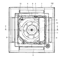
- FIG. 2 is a bottom view showing the indoor unit 102 of the air-conditioning apparatus 100 according to Embodiment 1 of the present invention with the suction grill removed.
- FIG. 3 is a cross-sectional view showing the indoor unit 102 of the air-conditioning apparatus 100 according to Embodiment 1 of the present invention, taken along the line XX of FIG.
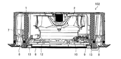
- FIG. 4 is an explanatory diagram showing the indoor unit 102 of the air-conditioning apparatus 100 according to Embodiment 1 of the present invention with the first and second sensor holders 10 and 11 attached to the electrical component box 9.
- the suction port 6 is formed in the central portion of the housing 7, and the blowout ports 8 for blowing conditioned air are formed on the four sides around the suction port 6. It is a ceiling-embedded indoor unit.
- the indoor unit 102 includes an electrical component box 9, a first sensor holder 10, a second sensor holder 11, a bell mouth 12, a drain pan 13, an indoor heat exchanger 1, and a blower 2 in a housing 7 from which a suction grill is removed. doing.
- a determination unit 5 is configured in the electrical component box 9, a determination unit 5 is configured.
- the electrical component box 9 is installed facing a suction side air passage that extends from the suction port 6 to the back.
- Two first and second sensor holders 10 and 11 are attached to the surface portion of the electrical component box 9 so as to face the suction port 6.
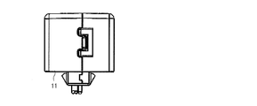
- the first sensor holder 10 is attached to the surface portion of the electrical component box 9 and incorporates the high sensitivity sensor 3 and the suction temperature sensor 14. Thereby, the high sensitivity sensor 3 is arrange
- the second sensor holder 11 is parallel to the first sensor holder 10 in the horizontal direction, is attached to the surface portion of the electrical component box 9, and incorporates the low sensitivity sensor 4.
- the second sensor holder 11 has no built-in suction temperature sensor. Thereby, the low sensitivity sensor 4 is arrange
- the position where the first and second sensor holders 10 and 11 are attached is a position below the indoor heat exchanger 1. Thereby, the low sensitivity sensor 4 is arrange
- the high sensitivity sensor 3 and the low sensitivity sensor 4 output analog output signals. For this reason, when a communication line such as a lead wire connected from the high sensitivity sensor 3 and the low sensitivity sensor 4 to the determination unit 5 runs in parallel with the power supply line or the blower 2, there is a concern that noise is added to the sensor output signal. On the other hand, when the first and second sensor holders 10 and 11 are directly installed in the electrical component box 9, the communication line is shortened and the adverse effect of noise is prevented.
- the high-sensitivity sensor 3 and the low-sensitivity sensor 4 are located in the vicinity of the suction port 6 so that the high-sensitivity sensor 3 or the low-sensitivity sensor 4 can detect when the refrigerant concentration of the indoor air becomes high within the range of the ignition lower limit concentration. Is installed.
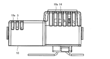
- FIG. 5 is a front view showing the first sensor holder 10 according to Embodiment 1 of the present invention.
- FIG. 6 is a left side view showing the first sensor holder 10 according to Embodiment 1 of the present invention.
- FIG. 7 is a right side view showing the first sensor holder 10 according to Embodiment 1 of the present invention.
- FIG. 8 is an internal development view showing the first sensor holder 10 according to Embodiment 1 of the present invention.
- the high sensitivity sensor 3 is built in the first sensor holder 10 together with the suction temperature sensor 14.
- a plurality of slits 10 a are formed in the first sensor holder 10 so that the high-sensitivity sensor 3 and the suction temperature sensor 14 directly come into the suction air.
- the high-sensitivity sensor 3 is configured mainly using a semiconductor sensitive gas element, and outputs due to the oxygen concentration.
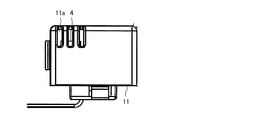
- FIG. 9 is a front view showing the second sensor holder 11 according to Embodiment 1 of the present invention.
- FIG. 10 is a left side view showing the second sensor holder 11 according to Embodiment 1 of the present invention.
- FIG. 11 is a right side view showing the second sensor holder 11 according to Embodiment 1 of the present invention.
- the low sensitivity sensor 4 is built in the second sensor holder 11.
- a plurality of slits 11 a are formed in the second sensor holder 11 so that the low-sensitivity sensor 4 directly receives the suction air.
- the low-sensitivity sensor 4 is configured mainly using a semiconductor sensitive gas element, and outputs due to the oxygen concentration.
- the low-sensitivity sensor 4 is output due to an oxygen concentration lower than that of the high-sensitivity sensor 3 from the beginning of manufacture, and detects the refrigerant with lower sensitivity than the high-sensitivity sensor 3.
- FIG. 12 is a block diagram showing an electrical component box 9 constituting the determination unit 5 according to Embodiment 1 of the present invention.
- the determination unit 5 is a processing circuit having a microcomputer including a CPU, a memory such as a ROM and a RAM, and an input / output device such as an I / O port.
- the control unit 110 mounted on the outdoor unit 101 has a processing circuit similar to that of the determination unit 5.
- the determination unit 5 detects the refrigerant leaked by the low sensitivity sensor 4 at all times or periodically regardless of whether the blower 2 is operated or stopped.
- the determination unit 5 detects the refrigerant leaked by the high sensitivity sensor 3 during operation of the blower 2.
- the determination unit 5 stops the detection of the high sensitivity sensor 3 when the blower 2 is stopped.
- the determination unit 5 transmits detection information to the control unit 110 of the outdoor unit 101 when the high sensitivity sensor 3 or the low sensitivity sensor 4 detects the leakage of the refrigerant.
- the control unit 110 of the outdoor unit 101 performs protection control such as pumping down so as to close an on-off valve in the refrigerant circuit and prevent the refrigerant from being supplied to the indoor unit 102.
- FIG. 13 is a diagram illustrating the detection timing for the leakage refrigerant concentration of the high-sensitivity sensor 3 and the low-sensitivity sensor 4 according to Embodiment 1 of the present invention.
- the vertical axis indicates the leakage refrigerant concentration in the indoor air.
- the horizontal axis is a time axis.
- the detection timing basically shows a proportional characteristic that rises to the right.
- the first detection point of the high sensitivity sensor 3 is a point when the leakage refrigerant concentration is the first threshold value.
- the first threshold value is a value at which erroneous detection by the high-sensitivity sensor 3 is issued when the blower 2 is stopped, for example, due to a decrease in oxygen concentration when the user sprays the pest control agent in the indoor space.
- the first threshold is the same component as the refrigerant that leaked when the blower 2 is stopped, for example, when the user sprays the deodorizing spray containing the same component as the refrigerant such as propane on the indoor space or the indoor unit 102. This is a value at which erroneous detection by the high-sensitivity sensor 3 due to the detection of is issued.
- the first threshold value is a value that is highly sensitive enough to be erroneously detected on a daily basis when the blower 2 is stopped.
- the second detection point of the low sensitivity sensor 4 is a point when the leaked refrigerant concentration is a second threshold value having a concentration higher than the first threshold value.
- the second threshold value is a value at which no erroneous detection is issued by the low-sensitivity sensor 4 due to a decrease in the oxygen concentration when the blower 2 is stopped, for example, when the user sprays the pest control agent in the indoor space.
- the second threshold value is the same component as the refrigerant that leaked when the blower 2 is stopped, for example, when the user sprays the deodorizing spray containing the same component as the refrigerant such as propane on the indoor space or the indoor unit 102. This is a value at which no false detection by the low-sensitivity sensor 4 due to the detection is issued.
- the second threshold value is a low-sensitivity value that does not cause erroneous detection on a daily basis when the blower 2 is stopped.
- the second threshold value is such that the leakage refrigerant concentration is lower than the lower limit ignition concentration value.
- the low-sensitivity sensor 4 lags behind the detection timing of the high-sensitivity sensor 3 after the refrigerant concentration is high, but leaks refrigerant at a point where the refrigerant concentration of indoor air is lower than the lower limit ignition concentration value. Can be detected.
- FIG. 14 is a flowchart showing a routine for detecting refrigerant leakage by the high sensitivity sensor 3 and the low sensitivity sensor 4 according to Embodiment 1 of the present invention. This routine is repeated sequentially.
- step S101 the determination unit 5 detects the refrigerant leaked by the low sensitivity sensor 4. As illustrated in FIG. 13, the low sensitivity sensor 4 notifies that the detection is performed when the leakage refrigerant concentration that has reached the second detection point is the second threshold value. After the process of step S101, the process proceeds to step S102.
- step S102 the determination unit 5 determines whether or not the blower 2 is in operation. When the blower 2 is in operation, the process proceeds to step S103. If the blower 2 is stopped, the process proceeds to step S104.
- step S103 the determination unit 5 detects the refrigerant leaked by the high sensitivity sensor 3.
- the high-sensitivity sensor 3 reports that the detection has been made when the leaked refrigerant concentration that has reached the first detection point is the first threshold value.
- the blower 2 since the refrigerant leaking into the room is detected when it is sucked from the suction port 6, it is quick to detect the sucked refrigerant with the high sensitivity sensor 3 having high sensitivity. is there.
- step S105 the process proceeds to step S105.
- step S104 the determination unit 5 stops the detection of the high sensitivity sensor 3. According to this, when the blower 2 is stopped, for example, it is possible to prevent erroneous detection by the high-sensitivity sensor 3 due to a decrease in oxygen concentration when the user sprays the pest control agent in the indoor space. Further, when the blower 2 is stopped, for example, the detection of the same component as the leaked refrigerant when the user sprays the deodorizing spray containing the same component as the refrigerant such as propane on the indoor space or the indoor unit 102. False detection by the high sensitivity sensor 3 can be prevented. Also in this case, since the low sensitivity sensor 4 is in the detection state, it can be detected whether the refrigerant leaks from any refrigerant pipe in the housing 7. After the process of step S104, the process proceeds to step S105.
- step S105 the determination unit 5 determines whether the high sensitivity sensor 3 or the low sensitivity sensor 4 has detected the leaked refrigerant. If refrigerant leakage is detected, the process proceeds to step S106. If no refrigerant leakage is detected, this routine is temporarily terminated.
- step S106 the determination unit 5 performs protection control such as pump down. This ensures the safety of the user. Thereafter, this routine is temporarily terminated.
- FIG. 15 is an explanatory diagram showing the indoor unit 102 of the air-conditioning apparatus 100 according to Modification 1 of Embodiment 1 of the present invention with the first and second sensor holders 10 and 11 attached to the electrical component box 9. is there.
- the same matters as those in the above embodiment are omitted, and only the characteristic portions will be described.
- the high sensitivity sensor 3 is disposed on the upstream side of the suction port 6 with respect to the low sensitivity sensor 4. That is, the two high sensitivity sensors 3 and the low sensitivity sensor 4 are installed side by side. In other words, the first and second sensor holders 10 and 11 are installed side by side.
- the low sensitivity sensor 4 is installed in a higher position, and it is easy to detect the refrigerant leaked from the indoor heat exchanger 1 when the blower 2 is stopped. The refrigerant leaked from the indoor heat exchanger 1 accumulates in the drain pan 13 and eventually leaks to the primary side where the suction port 6 is located. At that time, the low-sensitivity sensor 4 detects the refrigerant leaked quickly.
- the high-sensitivity sensor 3 and the low-sensitivity sensor 4 can reliably detect refrigerant leakage, the indoor air does not reach the lower limit ignition concentration, and the safe air conditioner 100 can be realized.
- the indoor unit 102 of the air conditioning apparatus 100 includes the high-sensitivity sensor 3 that detects the refrigerant leaked from the refrigerant pipe.
- the indoor unit 102 of the air conditioning apparatus 100 includes a low sensitivity sensor 4 that detects refrigerant leaked from the refrigerant pipe with lower sensitivity than the high sensitivity sensor 3.
- the high-sensitivity sensor 3 is disposed in the air inlet 6.
- the refrigerant is R32, it can be prevented from exceeding a concentration of 14 vol%.
- the low sensitivity sensor 4 is provided separately from the high sensitivity sensor 3. Thereby, when the blower 2 is stopped, if a refrigerant having a specific gravity greater than that of air stays at the bottom of the housing 7, the refrigerant leakage can be detected by the low sensitivity sensor 4. Even if one of the sensors 3 and 4 fails, the one sensor 3 and 4 can reliably detect the refrigerant leakage. Therefore, refrigerant leakage can be reliably detected not only when the blower 2 is stopped but also during operation.
- the low sensitivity sensor 4 is arranged in the air inlet 6.
- the refrigerant leakage can be detected by the low sensitivity sensor 4. Further, when the leaked refrigerant mixed with the indoor air after being blown out from the indoor unit 102 is sucked from the suction port 6, the refrigerant leakage can be detected later than the high sensitivity sensor 3 by the low sensitivity sensor 4. Thereby, the refrigerant concentration in the indoor space mixed with the refrigerant can be prevented from exceeding a certain lower limit ignition concentration. For example, if the refrigerant is R32, it can be prevented from exceeding a concentration of 14 vol%. Even if one of the sensors 3 and 4 fails, the one sensor 3 and 4 can reliably detect the refrigerant leakage. Therefore, refrigerant leakage can be reliably detected not only when the blower 2 is stopped but also during operation.
- the indoor unit 102 of the air conditioning apparatus 100 includes the blower 2.
- the indoor unit 102 of the air conditioning apparatus 100 includes a determination unit 5 that determines refrigerant leakage based on detection information from the high sensitivity sensor 3 and the low sensitivity sensor 4.
- the determination unit 5 detects the refrigerant leaked by the high sensitivity sensor 3 during operation of the blower 2.
- the sensitivity sensor 3 can quickly detect refrigerant leakage.
- the determination unit 5 stops the detection of the high sensitivity sensor 3 when the blower 2 is stopped.
- the blower 2 when the blower 2 is stopped, for example, it is possible to prevent erroneous detection by the high-sensitivity sensor 3 due to a decrease in oxygen concentration when the user sprays the pest control agent into the indoor space. Further, when the blower 2 is stopped, for example, the detection of the same component as the leaked refrigerant when the user sprays the deodorizing spray containing the same component as the refrigerant such as propane on the indoor space or the indoor unit 102. False detection by the high sensitivity sensor 3 can be prevented.
- the determination unit 5 detects the refrigerant leaked by the low sensitivity sensor 4 at all times or periodically regardless of whether the blower 2 is operated or stopped.
- the low-sensitivity sensor 4 can reliably detect refrigerant leakage when the refrigerant concentration in the indoor space in which the refrigerant is mixed does not exceed a certain lower limit ignition concentration. .
- the refrigerant is R32
- refrigerant leakage can be reliably detected by the low sensitivity sensor 4 when the concentration does not exceed 14 vol%.
- the indoor unit 102 of the air conditioning apparatus 100 includes the indoor heat exchanger 1.
- the low sensitivity sensor 4 is arranged at a position below the indoor heat exchanger 1.
- the determination unit 5 is configured in the electrical component box 9.
- the electrical component box 9 is installed facing a suction side air passage that extends from the suction port 6 to the back.
- a high-sensitivity sensor 3 is attached to the surface portion of the electrical component box 9.
- the high-sensitivity sensor 3 outputs an analog output signal. For this reason, when a communication line such as a lead wire that connects the high-sensitivity sensor 3 and the determination unit 5 runs in parallel with the power supply line or the blower 2, there is a concern that noise is added to the output signal of the high-sensitivity sensor 3. On the other hand, the high-sensitivity sensor 3 is attached to the surface portion of the electrical component box 9, the communication line is shortened, and adverse effects of noise can be avoided.
- the low sensitivity sensor 4 and the high sensitivity sensor 3 are attached to the surface portion of the electrical component box 9.
- some of the low-sensitivity sensors 4 output an analog output signal. For this reason, when a communication line such as a lead wire connecting the low-sensitivity sensor 4 and the determination unit 5 runs in parallel with the power supply line or the blower 2, there is a concern that noise is added to the output signal of the low-sensitivity sensor 4. On the other hand, the low sensitivity sensor 4 is attached to the surface portion of the electrical component box 9, the communication line is shortened, and the adverse effect of noise can be avoided.
- the high sensitivity sensor 3 is arranged on the upstream side of the suction port 6 with respect to the low sensitivity sensor 4.
- the high-sensitivity sensor 3 can quickly detect the refrigerant leak.
- the suction port 6 is formed in the central portion of the housing 7, and the air outlet 8 that blows out conditioned air is formed around the suction port 6. It is a ceiling-embedded indoor unit.
- the refrigerant at the outlet 8 is placed on the distribution path with a high concentration of refrigerant. If there is no leakage sensor, refrigerant leakage may not be detected.
- the high sensitivity sensor 3 is disposed in the suction port 6. For this reason, when the leaked refrigerant that has been blown out of the indoor unit 102 and mixed with the room air as a whole is sucked in from the suction port 6, the refrigerant leakage can be detected quickly by the high sensitivity sensor 3.
- the air conditioner 100 includes the indoor unit 102 of the air conditioner 100 described above.
- the air conditioner 100 including the indoor unit 102 of the air conditioner 100 can reliably detect refrigerant leakage not only when the blower 2 is stopped but also during operation.
Landscapes
- Engineering & Computer Science (AREA)
- Mechanical Engineering (AREA)
- General Engineering & Computer Science (AREA)
- Chemical & Material Sciences (AREA)
- Combustion & Propulsion (AREA)
- Physics & Mathematics (AREA)
- Thermal Sciences (AREA)
- Air Conditioning Control Device (AREA)
Abstract
La présente invention concerne une unité intérieure de dispositif de conditionnement d'air comprenant : un capteur à haute sensibilité qui détecte un fluide frigorigène s'échappant d'un tuyau de fluide frigorigène ; et un capteur à faible sensibilité qui détecte le fluide frigorigène s'échappant du tuyau de fluide frigorigène à une sensibilité inférieure à celle du capteur à haute sensibilité, le capteur à haute sensibilité étant disposé au niveau d'un orifice d'entrée d'air.
Priority Applications (2)
| Application Number | Priority Date | Filing Date | Title |
|---|---|---|---|
| PCT/JP2018/021963 WO2019234902A1 (fr) | 2018-06-08 | 2018-06-08 | Unité intérieure de dispositif de conditionnement d'air et dispositif de conditionnement d'air |
| JP2020523947A JP6949217B2 (ja) | 2018-06-08 | 2018-06-08 | 空気調和装置の室内機及び空気調和装置 |
Applications Claiming Priority (1)
| Application Number | Priority Date | Filing Date | Title |
|---|---|---|---|
| PCT/JP2018/021963 WO2019234902A1 (fr) | 2018-06-08 | 2018-06-08 | Unité intérieure de dispositif de conditionnement d'air et dispositif de conditionnement d'air |
Publications (1)
| Publication Number | Publication Date |
|---|---|
| WO2019234902A1 true WO2019234902A1 (fr) | 2019-12-12 |
Family
ID=68770808
Family Applications (1)
| Application Number | Title | Priority Date | Filing Date |
|---|---|---|---|
| PCT/JP2018/021963 WO2019234902A1 (fr) | 2018-06-08 | 2018-06-08 | Unité intérieure de dispositif de conditionnement d'air et dispositif de conditionnement d'air |
Country Status (2)
| Country | Link |
|---|---|
| JP (1) | JP6949217B2 (fr) |
| WO (1) | WO2019234902A1 (fr) |
Citations (2)
| Publication number | Priority date | Publication date | Assignee | Title |
|---|---|---|---|---|
| JP2016090175A (ja) * | 2014-11-07 | 2016-05-23 | 日立アプライアンス株式会社 | 室内機、および、それを備える空気調和機 |
| WO2016151641A1 (fr) * | 2015-03-26 | 2016-09-29 | 三菱電機株式会社 | Unité intérieure de climatiseur |
-
2018
- 2018-06-08 WO PCT/JP2018/021963 patent/WO2019234902A1/fr active Application Filing
- 2018-06-08 JP JP2020523947A patent/JP6949217B2/ja active Active
Patent Citations (2)
| Publication number | Priority date | Publication date | Assignee | Title |
|---|---|---|---|---|
| JP2016090175A (ja) * | 2014-11-07 | 2016-05-23 | 日立アプライアンス株式会社 | 室内機、および、それを備える空気調和機 |
| WO2016151641A1 (fr) * | 2015-03-26 | 2016-09-29 | 三菱電機株式会社 | Unité intérieure de climatiseur |
Also Published As
| Publication number | Publication date |
|---|---|
| JPWO2019234902A1 (ja) | 2021-01-14 |
| JP6949217B2 (ja) | 2021-10-13 |
Similar Documents
| Publication | Publication Date | Title |
|---|---|---|
| JP6388735B2 (ja) | 空気調和装置 | |
| US11067303B2 (en) | Air-conditioning apparatus | |
| WO2019215877A1 (fr) | Dispositif de détermination de fuite de fluide frigorigène, climatiseur et procédé de détermination de fuite de fluide frigorigène | |
| JP6168113B2 (ja) | 空調室内機 | |
| JP6431339B2 (ja) | 室内機、および、それを備える空気調和機 | |
| US20210041114A1 (en) | Indoor unit of air-conditioning apparatus, and air-conditioning apparatus including the indoor unit | |
| JP6656406B2 (ja) | 空気調和装置および冷媒漏洩検知方法 | |
| CN114127478B (zh) | 冷冻装置的室内机 | |
| EP3517856B1 (fr) | Procédé et appareil de confirmation d'étalonnage d'un détecteur de fluide frigorigène | |
| US20230235907A1 (en) | Leakage detection and mitigation system | |
| WO2019102729A1 (fr) | Climatiseur | |
| JP7315845B2 (ja) | 空気調和装置 | |
| WO2019234902A1 (fr) | Unité intérieure de dispositif de conditionnement d'air et dispositif de conditionnement d'air | |
| JP2021085644A (ja) | 空調システム | |
| US20200132320A1 (en) | Detecting blockage of air conditioner unit based on control signal | |
| JPWO2019138534A1 (ja) | 空気調和装置 | |
| WO2019198176A1 (fr) | Unité intérieure pour dispositif de climatisation | |
| JP2021085642A (ja) | 空気調和装置 | |
| JP2008202868A (ja) | 空気調和機 | |
| JP2008249288A (ja) | 空気調和機 | |
| CN110410934A (zh) | 一种空调器制冷剂泄漏处理方法、装置及空调器 | |
| CN220958668U (zh) | 一种空调室内机及空调系统 | |
| US20240044533A1 (en) | Air conditioning system, operation control method therefor, and operation control device for air conditioning system | |
| JP2006242438A (ja) | 冷凍サイクル機器 |
Legal Events
| Date | Code | Title | Description |
|---|---|---|---|
| 121 | Ep: the epo has been informed by wipo that ep was designated in this application |
Ref document number: 18922023 Country of ref document: EP Kind code of ref document: A1 |
|
| ENP | Entry into the national phase |
Ref document number: 2020523947 Country of ref document: JP Kind code of ref document: A |
|
| NENP | Non-entry into the national phase |
Ref country code: DE |
|
| 122 | Ep: pct application non-entry in european phase |
Ref document number: 18922023 Country of ref document: EP Kind code of ref document: A1 |