WO2019230862A1 - 接合体及びその製造方法 - Google Patents
接合体及びその製造方法 Download PDFInfo
- Publication number
- WO2019230862A1 WO2019230862A1 PCT/JP2019/021452 JP2019021452W WO2019230862A1 WO 2019230862 A1 WO2019230862 A1 WO 2019230862A1 JP 2019021452 W JP2019021452 W JP 2019021452W WO 2019230862 A1 WO2019230862 A1 WO 2019230862A1
- Authority
- WO
- WIPO (PCT)
- Prior art keywords
- plasma
- rubber
- resin
- resin body
- sheet
- Prior art date
- Legal status (The legal status is an assumption and is not a legal conclusion. Google has not performed a legal analysis and makes no representation as to the accuracy of the status listed.)
- Ceased
Links
Images
Classifications
-
- B—PERFORMING OPERATIONS; TRANSPORTING
- B32—LAYERED PRODUCTS
- B32B—LAYERED PRODUCTS, i.e. PRODUCTS BUILT-UP OF STRATA OF FLAT OR NON-FLAT, e.g. CELLULAR OR HONEYCOMB, FORM
- B32B7/00—Layered products characterised by the relation between layers; Layered products characterised by the relative orientation of features between layers, or by the relative values of a measurable parameter between layers, i.e. products comprising layers having different physical, chemical or physicochemical properties; Layered products characterised by the interconnection of layers
- B32B7/04—Interconnection of layers
-
- B—PERFORMING OPERATIONS; TRANSPORTING
- B32—LAYERED PRODUCTS
- B32B—LAYERED PRODUCTS, i.e. PRODUCTS BUILT-UP OF STRATA OF FLAT OR NON-FLAT, e.g. CELLULAR OR HONEYCOMB, FORM
- B32B15/00—Layered products comprising a layer of metal
- B32B15/04—Layered products comprising a layer of metal comprising metal as the main or only constituent of a layer, which is next to another layer of the same or of a different material
- B32B15/06—Layered products comprising a layer of metal comprising metal as the main or only constituent of a layer, which is next to another layer of the same or of a different material of natural rubber or synthetic rubber
-
- B—PERFORMING OPERATIONS; TRANSPORTING
- B32—LAYERED PRODUCTS
- B32B—LAYERED PRODUCTS, i.e. PRODUCTS BUILT-UP OF STRATA OF FLAT OR NON-FLAT, e.g. CELLULAR OR HONEYCOMB, FORM
- B32B15/00—Layered products comprising a layer of metal
- B32B15/18—Layered products comprising a layer of metal comprising iron or steel
-
- B—PERFORMING OPERATIONS; TRANSPORTING
- B32—LAYERED PRODUCTS
- B32B—LAYERED PRODUCTS, i.e. PRODUCTS BUILT-UP OF STRATA OF FLAT OR NON-FLAT, e.g. CELLULAR OR HONEYCOMB, FORM
- B32B15/00—Layered products comprising a layer of metal
- B32B15/20—Layered products comprising a layer of metal comprising aluminium or copper
-
- B—PERFORMING OPERATIONS; TRANSPORTING
- B32—LAYERED PRODUCTS
- B32B—LAYERED PRODUCTS, i.e. PRODUCTS BUILT-UP OF STRATA OF FLAT OR NON-FLAT, e.g. CELLULAR OR HONEYCOMB, FORM
- B32B17/00—Layered products essentially comprising sheet glass, or glass, slag, or like fibres
- B32B17/06—Layered products essentially comprising sheet glass, or glass, slag, or like fibres comprising glass as the main or only constituent of a layer, next to another layer of a specific material
- B32B17/10—Layered products essentially comprising sheet glass, or glass, slag, or like fibres comprising glass as the main or only constituent of a layer, next to another layer of a specific material of synthetic resin
-
- B—PERFORMING OPERATIONS; TRANSPORTING
- B32—LAYERED PRODUCTS
- B32B—LAYERED PRODUCTS, i.e. PRODUCTS BUILT-UP OF STRATA OF FLAT OR NON-FLAT, e.g. CELLULAR OR HONEYCOMB, FORM
- B32B25/00—Layered products comprising a layer of natural or synthetic rubber
- B32B25/04—Layered products comprising a layer of natural or synthetic rubber comprising rubber as the main or only constituent of a layer, which is next to another layer of the same or of a different material
- B32B25/08—Layered products comprising a layer of natural or synthetic rubber comprising rubber as the main or only constituent of a layer, which is next to another layer of the same or of a different material of synthetic resin
-
- B—PERFORMING OPERATIONS; TRANSPORTING
- B32—LAYERED PRODUCTS
- B32B—LAYERED PRODUCTS, i.e. PRODUCTS BUILT-UP OF STRATA OF FLAT OR NON-FLAT, e.g. CELLULAR OR HONEYCOMB, FORM
- B32B25/00—Layered products comprising a layer of natural or synthetic rubber
- B32B25/20—Layered products comprising a layer of natural or synthetic rubber comprising silicone rubber
-
- B—PERFORMING OPERATIONS; TRANSPORTING
- B32—LAYERED PRODUCTS
- B32B—LAYERED PRODUCTS, i.e. PRODUCTS BUILT-UP OF STRATA OF FLAT OR NON-FLAT, e.g. CELLULAR OR HONEYCOMB, FORM
- B32B27/00—Layered products comprising a layer of synthetic resin
- B32B27/16—Layered products comprising a layer of synthetic resin specially treated, e.g. irradiated
-
- B—PERFORMING OPERATIONS; TRANSPORTING
- B32—LAYERED PRODUCTS
- B32B—LAYERED PRODUCTS, i.e. PRODUCTS BUILT-UP OF STRATA OF FLAT OR NON-FLAT, e.g. CELLULAR OR HONEYCOMB, FORM
- B32B27/00—Layered products comprising a layer of synthetic resin
- B32B27/28—Layered products comprising a layer of synthetic resin comprising synthetic resins not wholly covered by any one of the sub-groups B32B27/30 - B32B27/42
- B32B27/281—Layered products comprising a layer of synthetic resin comprising synthetic resins not wholly covered by any one of the sub-groups B32B27/30 - B32B27/42 comprising polyimides
-
- B—PERFORMING OPERATIONS; TRANSPORTING
- B32—LAYERED PRODUCTS
- B32B—LAYERED PRODUCTS, i.e. PRODUCTS BUILT-UP OF STRATA OF FLAT OR NON-FLAT, e.g. CELLULAR OR HONEYCOMB, FORM
- B32B27/00—Layered products comprising a layer of synthetic resin
- B32B27/28—Layered products comprising a layer of synthetic resin comprising synthetic resins not wholly covered by any one of the sub-groups B32B27/30 - B32B27/42
- B32B27/285—Layered products comprising a layer of synthetic resin comprising synthetic resins not wholly covered by any one of the sub-groups B32B27/30 - B32B27/42 comprising polyethers
-
- B—PERFORMING OPERATIONS; TRANSPORTING
- B32—LAYERED PRODUCTS
- B32B—LAYERED PRODUCTS, i.e. PRODUCTS BUILT-UP OF STRATA OF FLAT OR NON-FLAT, e.g. CELLULAR OR HONEYCOMB, FORM
- B32B27/00—Layered products comprising a layer of synthetic resin
- B32B27/28—Layered products comprising a layer of synthetic resin comprising synthetic resins not wholly covered by any one of the sub-groups B32B27/30 - B32B27/42
- B32B27/286—Layered products comprising a layer of synthetic resin comprising synthetic resins not wholly covered by any one of the sub-groups B32B27/30 - B32B27/42 comprising polysulphones; polysulfides
-
- B—PERFORMING OPERATIONS; TRANSPORTING
- B32—LAYERED PRODUCTS
- B32B—LAYERED PRODUCTS, i.e. PRODUCTS BUILT-UP OF STRATA OF FLAT OR NON-FLAT, e.g. CELLULAR OR HONEYCOMB, FORM
- B32B27/00—Layered products comprising a layer of synthetic resin
- B32B27/28—Layered products comprising a layer of synthetic resin comprising synthetic resins not wholly covered by any one of the sub-groups B32B27/30 - B32B27/42
- B32B27/288—Layered products comprising a layer of synthetic resin comprising synthetic resins not wholly covered by any one of the sub-groups B32B27/30 - B32B27/42 comprising polyketones
-
- B—PERFORMING OPERATIONS; TRANSPORTING
- B32—LAYERED PRODUCTS
- B32B—LAYERED PRODUCTS, i.e. PRODUCTS BUILT-UP OF STRATA OF FLAT OR NON-FLAT, e.g. CELLULAR OR HONEYCOMB, FORM
- B32B27/00—Layered products comprising a layer of synthetic resin
- B32B27/30—Layered products comprising a layer of synthetic resin comprising vinyl (co)polymers; comprising acrylic (co)polymers
-
- B—PERFORMING OPERATIONS; TRANSPORTING
- B32—LAYERED PRODUCTS
- B32B—LAYERED PRODUCTS, i.e. PRODUCTS BUILT-UP OF STRATA OF FLAT OR NON-FLAT, e.g. CELLULAR OR HONEYCOMB, FORM
- B32B27/00—Layered products comprising a layer of synthetic resin
- B32B27/30—Layered products comprising a layer of synthetic resin comprising vinyl (co)polymers; comprising acrylic (co)polymers
- B32B27/302—Layered products comprising a layer of synthetic resin comprising vinyl (co)polymers; comprising acrylic (co)polymers comprising aromatic vinyl (co)polymers, e.g. styrenic (co)polymers
-
- B—PERFORMING OPERATIONS; TRANSPORTING
- B32—LAYERED PRODUCTS
- B32B—LAYERED PRODUCTS, i.e. PRODUCTS BUILT-UP OF STRATA OF FLAT OR NON-FLAT, e.g. CELLULAR OR HONEYCOMB, FORM
- B32B27/00—Layered products comprising a layer of synthetic resin
- B32B27/30—Layered products comprising a layer of synthetic resin comprising vinyl (co)polymers; comprising acrylic (co)polymers
- B32B27/304—Layered products comprising a layer of synthetic resin comprising vinyl (co)polymers; comprising acrylic (co)polymers comprising vinyl halide (co)polymers, e.g. PVC, PVDC, PVF, PVDF
-
- B—PERFORMING OPERATIONS; TRANSPORTING
- B32—LAYERED PRODUCTS
- B32B—LAYERED PRODUCTS, i.e. PRODUCTS BUILT-UP OF STRATA OF FLAT OR NON-FLAT, e.g. CELLULAR OR HONEYCOMB, FORM
- B32B27/00—Layered products comprising a layer of synthetic resin
- B32B27/32—Layered products comprising a layer of synthetic resin comprising polyolefins
-
- B—PERFORMING OPERATIONS; TRANSPORTING
- B32—LAYERED PRODUCTS
- B32B—LAYERED PRODUCTS, i.e. PRODUCTS BUILT-UP OF STRATA OF FLAT OR NON-FLAT, e.g. CELLULAR OR HONEYCOMB, FORM
- B32B27/00—Layered products comprising a layer of synthetic resin
- B32B27/32—Layered products comprising a layer of synthetic resin comprising polyolefins
- B32B27/322—Layered products comprising a layer of synthetic resin comprising polyolefins comprising halogenated polyolefins, e.g. PTFE
-
- B—PERFORMING OPERATIONS; TRANSPORTING
- B32—LAYERED PRODUCTS
- B32B—LAYERED PRODUCTS, i.e. PRODUCTS BUILT-UP OF STRATA OF FLAT OR NON-FLAT, e.g. CELLULAR OR HONEYCOMB, FORM
- B32B27/00—Layered products comprising a layer of synthetic resin
- B32B27/32—Layered products comprising a layer of synthetic resin comprising polyolefins
- B32B27/325—Layered products comprising a layer of synthetic resin comprising polyolefins comprising polycycloolefins
-
- B—PERFORMING OPERATIONS; TRANSPORTING
- B32—LAYERED PRODUCTS
- B32B—LAYERED PRODUCTS, i.e. PRODUCTS BUILT-UP OF STRATA OF FLAT OR NON-FLAT, e.g. CELLULAR OR HONEYCOMB, FORM
- B32B27/00—Layered products comprising a layer of synthetic resin
- B32B27/36—Layered products comprising a layer of synthetic resin comprising polyesters
-
- C—CHEMISTRY; METALLURGY
- C08—ORGANIC MACROMOLECULAR COMPOUNDS; THEIR PREPARATION OR CHEMICAL WORKING-UP; COMPOSITIONS BASED THEREON
- C08J—WORKING-UP; GENERAL PROCESSES OF COMPOUNDING; AFTER-TREATMENT NOT COVERED BY SUBCLASSES C08B, C08C, C08F, C08G or C08H
- C08J5/00—Manufacture of articles or shaped materials containing macromolecular substances
- C08J5/12—Bonding of a preformed macromolecular material to the same or other solid material such as metal, glass, leather, e.g. using adhesives
-
- C—CHEMISTRY; METALLURGY
- C08—ORGANIC MACROMOLECULAR COMPOUNDS; THEIR PREPARATION OR CHEMICAL WORKING-UP; COMPOSITIONS BASED THEREON
- C08J—WORKING-UP; GENERAL PROCESSES OF COMPOUNDING; AFTER-TREATMENT NOT COVERED BY SUBCLASSES C08B, C08C, C08F, C08G or C08H
- C08J7/00—Chemical treatment or coating of shaped articles made of macromolecular substances
-
- B—PERFORMING OPERATIONS; TRANSPORTING
- B32—LAYERED PRODUCTS
- B32B—LAYERED PRODUCTS, i.e. PRODUCTS BUILT-UP OF STRATA OF FLAT OR NON-FLAT, e.g. CELLULAR OR HONEYCOMB, FORM
- B32B2307/00—Properties of the layers or laminate
- B32B2307/70—Other properties
- B32B2307/748—Releasability
-
- B—PERFORMING OPERATIONS; TRANSPORTING
- B32—LAYERED PRODUCTS
- B32B—LAYERED PRODUCTS, i.e. PRODUCTS BUILT-UP OF STRATA OF FLAT OR NON-FLAT, e.g. CELLULAR OR HONEYCOMB, FORM
- B32B2310/00—Treatment by energy or chemical effects
- B32B2310/14—Corona, ionisation, electrical discharge, plasma treatment
Definitions
- the present invention relates to a joined body and a manufacturing method thereof.
- etching treatment ultraviolet treatment, chemical vapor deposition treatment, plasma treatment and the like have been performed in order to impart various functions to the surface of a molded body containing a fluororesin. Molded products molded with fluororesins have low surface wettability and are difficult to bond with adhesives, so etching and plasma treatments are used to improve the surface adhesion of molded products. Has been done.
- Patent Document 1 describes a surface modification method in which plasma irradiation is performed, ions in plasma are injected into the surface of the molded body, and fluorine atoms on the surface of the molded body are replaced with atoms other than fluorine atoms.
- Patent Document 2 describes a fluororesin molded body in which fine projections are formed by surface modification of a fluororesin by ion implantation treatment.
- Patent Document 3 discloses a fluororesin layer having a plasma-monomer polymerization layer on the surface, and describes that surface modification and grafting are performed simultaneously.
- the surface temperature of the molded body containing the organic polymer compound is set to (the melting point of the organic polymer compound ⁇ 120) ° C. or higher, and the surface of the molded body is set.
- a method for producing a surface-modified molded article which is characterized by performing atmospheric pressure plasma treatment and introducing peroxide radicals.
- An object of the present invention is to provide a joined body of a resin body containing a fluororesin and a rubber body containing a vulcanized silicone rubber.
- the gist of the present invention is as follows.
- the present invention is a joined body of a resin body containing a fluororesin and a rubber body containing vulcanized silicone rubber.
- the vulcanized silicone rubber contains a dimethylsiloxane unit.
- the fluororesin is a copolymer of at least one of a hexafluoropropylene unit, a perfluoroalkyl vinyl ether unit, a methylene unit, an ethylene unit and a perfluorodioxole unit and a difluoromethylene unit, or polytetrafluoroethylene. It is preferable.
- At least one surface of the resin body and at least one surface of the rubber body are subjected to plasma treatment, and the plasma-treated surfaces are joined to each other.
- the adhesive strength between the resin body and the rubber body is 1.0 N / mm or more.
- the present invention also includes a method for manufacturing a joined body of a resin body containing a fluorine-based resin and a rubber body containing silicone rubber.
- the above manufacturing method reduces the oxygen concentration near the surface of the resin body to 0. Less than 5% by volume, the surface of the resin body is subjected to plasma treatment to produce a surface-modified resin body, and the oxygen concentration in the vicinity of the surface of the rubber body is set to 1% by volume or more.
- a surface treatment process for producing a surface-modified rubber body, a modified surface of the surface-modified resin body, and a modified surface of the surface-modified rubber body And a step of heating and pressurizing.
- the rubber body By performing a predetermined plasma treatment on the surface of the rubber body containing the vulcanized silicone rubber, the rubber body could be adhered to the resin body containing the fluororesin.
- metal or glass adheres to the surface of a rubber body containing vulcanized silicone rubber. Therefore, by adhering metal or glass to the surface of the rubber body in the joined body of the present invention, it is possible to overlap the resin body, the rubber body, and the metal in this order, or the resin body, the rubber body, and the glass in this order. That is, a resin body containing a fluorine resin can be bonded to metal or glass without using an adhesive.
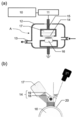
- FIG. 1 It is a conceptual diagram of an atmospheric pressure plasma processing apparatus, (a) is a whole side view, (b) is a top view which shows the relationship between a rod-shaped electrode and a board
- a resin body containing a fluororesin (hereinafter simply referred to as a resin body) and a rubber body containing a vulcanized silicone rubber (hereinafter sometimes simply referred to as a rubber body) are joined.
- the resin body and the rubber body are directly joined without using an adhesive.
- at least one surface of the resin body and at least one surface of the rubber body are subjected to plasma treatment, and the surfaces subjected to the plasma treatment are bonded to each other.
- the fluororesin refers to a resin containing a fluorine atom in a molecule.
- the fluororesin is a copolymer of at least one of a hexafluoropropylene unit, a perfluoroalkyl vinyl ether unit, a methylene unit, an ethylene unit and a perfluorodioxole unit and a difluoromethylene unit, or polytetrafluoroethylene.
- the fluororesin is preferably a hexafluoropropylene unit, a perfluoroalkyl vinyl ether unit, an ethylene unit or a copolymer of a perfluorodioxole unit and a tetrafluoroethylene unit, or polytetrafluoroethylene.
- fluororesins examples include polytetrafluoroethylene (PTFE), polychlorotrifluoroethylene (PCTFE), polyvinylidene fluoride (PVDF), polyvinyl fluoride (PVF), and tetrafluoroethylene-hexafluoropropylene copolymer (FEP). ), Tetrafluoroethylene-perfluoroalkyl vinyl ether copolymer (PFA), tetrafluoroethylene-ethylene copolymer (ETFE), tetrafluoroethylene-perfluorodioxole copolymer (TFE / PDD), chlorotrifluoro And ethylene-ethylene copolymer (ECTFE).
- PTFE polytetrafluoroethylene
- PCTFE polychlorotrifluoroethylene
- PVDF polyvinylidene fluoride
- PVF polyvinyl fluoride
- FEP tetrafluoroethylene-hexafluoropropylene copo
- PTFE substitution ratio of fluorine atoms
- PFA substitution ratio of fluorine atoms
- ETFE substitution ratio of fluorine atoms
- FEP substitution ratio of fluorine atoms
- the resin body used in the present invention may contain a resin other than the above-described fluororesin.
- resins other than fluorine resins include olefin resins such as polyethylene resins, polypropylene resins and cycloolefin resins; polyester resins such as polyethylene terephthalate resins; polyimide resins; styrene resins such as styrene resins and syndiotactic polystyrene resins.
- the fluororesin is contained in an amount exceeding 50 parts by mass, preferably 80 parts by mass or more, and 90 parts by mass or more. Is more preferably 95 parts by mass or more, particularly preferably 99 parts by mass or more, and most preferably 100 parts by mass (containing only the fluororesin).
- the form of the resin body that can be used in the present invention is not particularly limited as long as it is a shape capable of plasma irradiation, which will be described later, and can be applied to those having various shapes and structures. Examples thereof include, but are not limited to, a square shape, a spherical shape, and a thin film shape having a surface shape such as a flat surface, a curved surface, and a bent surface.
- the resin body may be molded by various molding methods such as injection molding, melt extrusion molding, paste extrusion molding, compression molding, cutting molding, cast molding, and impregnation molding depending on the characteristics of the fluororesin. Further, the resin body may have a dense continuous structure, such as a normal injection molded body, a porous structure, a non-woven fabric, or other structures. good.
- the vulcanized silicone rubber preferably contains a siloxane unit, and more preferably contains a dimethylsiloxane unit.
- vulcanized silicone rubber is produced by vulcanizing (crosslinking) polysiloxane.
- the polysiloxane is not particularly limited as long as it has a Si—O structure, and examples thereof include chain polysiloxanes such as polydimethylsiloxane, methylphenylpolysiloxane, and methylhydrogenpolysiloxane, decamethylcyclopentasiloxane, and dodecamethyl.
- cyclic polysiloxanes such as cyclohexasiloxane
- 1 type may be used independently among these polysiloxanes and they may be used in combination of 2 or more type.
- the polysiloxane preferably contains a linear polysiloxane, more preferably polydimethylsiloxane (PDMS).
- PDMS polydimethylsiloxane
- the rubber body used in the present invention may contain rubber other than vulcanized silicone rubber.
- rubbers other than vulcanized silicone rubber include butadiene rubber, isoprene rubber, butyl rubber, fluorine rubber, ethylene propylene rubber, nitrile rubber, and natural rubber. More than 50 parts by mass of vulcanized silicone rubber is contained in 100 parts by mass of the rubber body, preferably 80 parts by mass or more, more preferably 90 parts by mass or more, and 95 parts by mass. More preferably, it is more preferably 99 parts by mass or more, and most preferably 100 parts by mass (containing only vulcanized silicone rubber).
- the crosslinking agent is preferably 1 part by mass or more, more preferably 1.5 parts by mass or more, still more preferably 2 parts by mass or more, and 10 parts by mass or less in 100 parts by mass of the rubber body. Preferably, it is 7 parts by mass or less, more preferably 5 parts by mass or less, and particularly preferably 3 parts by mass or less.
- the rubber composition may contain other additives such as a vulcanization accelerator, a crosslinking aid, a reinforcing agent, an acid acceptor, a plasticizer, a heat resistance inhibitor, and a colorant, which are blended in a normal rubber composition. May be included.
- the content of these other additives is preferably 10 parts by mass or less in total in 100 parts by mass of the rubber body, more preferably 7 parts by mass or less, still more preferably 5 parts by mass or less, Particularly preferably, it is 3 parts by mass or less.
- silicone rubber examples include KE-571-U, KE-1571-U, KE-951-U, KE-541-U, KE-551-U, and KE-561-U manufactured by Shin-Etsu Chemical Co., Ltd. KE-961T-U, KE-1541-U, KE-1551-U, KE-941-U, KE-971T-U, and the like can be used.
- Silicone rubber is cross-linked by a cross-linking agent.
- the crosslinking agent include an addition reaction crosslinking agent and / or an organic peroxide crosslinking agent, and an addition vulcanized silicone rubber produced using the addition reaction crosslinking agent is preferable.
- addition reaction crosslinking agent for example, a known organohydrogenpolysiloxane is preferably mentioned as an addition reaction type crosslinking agent having two or more SiH groups (SiH bonds) in one molecule.
- One type of addition reaction crosslinking agent may be included, or two or more types may be included.
- the addition amount of the addition reaction crosslinking agent is usually 0.1 to 3.0 parts by mass with respect to 100 parts by mass of the silicone rubber.
- the silicone peroxide can be crosslinked with the organic peroxide crosslinking agent alone, but it may be used in combination as an auxiliary crosslinking agent for the addition reaction crosslinking agent.
- the organic peroxide crosslinking agent include benzoyl peroxide, bis-2,4-dichlorobenzoyl peroxide, dicumyl peroxide, di-t-butyl peroxide, 2,5-dimethyl-2,5-bis. And (t-butylperoxy) hexane.
- the amount of the organic peroxide crosslinking agent is usually 0.1 to 5.0 parts by mass with respect to 100 parts by mass of the silicone rubber.
- the organic peroxide crosslinking agent may be one type or may contain two or more types.
- the addition reaction crosslinking agent is preferably used in combination with an addition reaction catalyst.
- the addition reaction catalyst is preferably a platinum group metal simple substance and its compound, but fine platinum metal adsorbed on a carrier such as silica, alumina or silica gel, platinum chloride, chloroplatinic acid, platinum chloride.
- An acid hexahydrate alcohol solution, a palladium catalyst, a rhodium catalyst, or the like may be used.
- the amount of the addition reaction catalyst is usually 1 ppm to 1.0 part by mass with respect to 100 parts by mass of the silicone rubber.
- the addition reaction catalyst may be one type or two or more types.
- Plasma treatment is performed on the surface of the resin body in the state where oxygen is not present as much as possible near the surface of the resin body containing the fluororesin, and peroxide radicals are formed on the surface of the resin body.
- the surface of the resin body is modified by forming it sufficiently.
- the oxygen concentration in the vicinity of the surface of the resin body may be less than 0.5% by volume, and the surface of the resin body may be subjected to plasma treatment to produce a surface-modified resin body.
- the surface modification of the resin body may be performed by performing a treatment with atmospheric pressure plasma in a state where the surface temperature of the resin body is increased.
- the surface of the resin body is preferably subjected to surface modification by performing treatment with atmospheric pressure plasma at a surface temperature of (melting point of fluororesin ⁇ 150) ° C. or higher.
- the mobility of the polymer of the polymer compound on the surface of the resin body that is the target of plasma irradiation is increased.
- a polymer compound having such a high mobility is irradiated with plasma
- the bond between the carbon atom of the polymer compound and the carbon atom or other atoms is broken
- the carbon atoms whose bonds are broken can undergo a cross-linking reaction to sufficiently form peroxide radicals on the surface of the resin body.
- the surface temperature of the resin body is preferably within the above range, more preferably 180 ° C. or higher, and further preferably 200 ° C. or higher.
- the upper limit of the surface temperature of the resin body is not particularly limited, but may be, for example, (melting point + 20) ° C. or lower.
- the surface of the resin body containing the fluororesin is modified by atmospheric pressure plasma.
- the conditions for the treatment with the atmospheric pressure plasma are not particularly limited as long as the surface temperature and the output power density of the resin body can be within the predetermined ranges. Conditions that are capable of generating atmospheric pressure plasma, which are employed in the technical field of performing surface modification of a resin body by plasma, can be appropriately employed.
- the surface temperature of the resin body is set to a predetermined temperature range in which the mobility of the fluororesin polymer on the surface of the resin body can be increased, atmospheric pressure plasma treatment is performed. In the case where the surface temperature is raised only by the heating effect by the plasma treatment, it is preferable to perform the atmospheric pressure plasma treatment under the condition that the heating effect is obtained.
- a high frequency power source having an applied voltage frequency of 50 Hz to 2.45 GHz may be used.
- the output power density (output power per unit area) may be 15 W / cm 2 or more, and the upper limit is not particularly limited, For example, it may be 40 W / cm 2 or less.
- the pulse modulation frequency is preferably 1 to 50 kHz (preferably 5 to 30 kHz), and the pulse duty is 5 to 99% (preferably 15 to 80%, more preferably 25 to 70%).
- a cylindrical or flat metal having at least one side coated with a dielectric can be used.
- the distance between the opposed electrodes depends on other conditions, but is preferably 5 mm or less, more preferably 3 mm or less, still more preferably 2 mm or less, particularly preferably 1 mm or less from the viewpoint of plasma generation and heating. is there.
- the minimum of the distance between the electrodes made to oppose is not specifically limited, For example, it is 0.5 mm or more.
- a rare gas such as helium, argon, or neon
- a reactive gas such as oxygen, nitrogen, or hydrogen
- these gases may use only 1 type, or 2 or more types of noble gases, or a mixed gas of 1 type or 2 types or more of noble gases and an appropriate amount of 1 type or 2 types or more of reactive gases. It may be used.
- the generation of the plasma may be performed under the above-described conditions in which the gas atmosphere is controlled using a chamber, or may be performed under a completely open atmosphere condition in which, for example, a rare gas is flowed to the electrode portion.
- the surface of the resin body opposite to the plasma irradiation surface is hardly affected by the plasma treatment (the effect of improving the hardness is smaller than that of the plasma irradiation surface).
- Various characteristics for example, chemical resistance, weather resistance, heat resistance, electrical insulation, etc. that are inherently exhibited without fail are fully exhibited.
- FIG. 1 is a conceptual diagram of a capacitively coupled atmospheric pressure plasma processing apparatus that is an example of an atmospheric pressure plasma processing apparatus that can be used in the present invention.
- An atmospheric pressure plasma processing apparatus A shown in FIG. 1A includes a high-frequency power source 10, a matching unit 11, a chamber 12, an evacuation system 13, an electrode 14, an electrode lifting mechanism 15, a grounded cylindrical rotary stage and a sample holder 16.
- the rotary stage control unit (not shown) is configured.
- the rotary stage 16 is disposed so as to face the electrode 14.
- the cylindrical rotary stage and the sample holder 16 for example, those made of aluminum alloy can be used.
- the electrode 14 has a rod-like shape, for example, a structure in which the surface of an inner tube 18 made of copper is covered with an outer tube 19 of, for example, aluminum oxide (Al 2 O 3 ). It can be used.
- the surface modification method of the resin body using the atmospheric pressure plasma processing apparatus A shown in FIG. 1 is as follows. First, the resin body is washed with an organic solvent such as acetone or water such as ultrapure water as necessary, and then a sheet-shaped sample (fluorine) is placed on the sample holder 16 in the chamber 12 as shown in FIG. After the resin body 20 including the resin is disposed, the air in the chamber 12 is sucked from the vacuum exhaust system 13 by a suction device (not shown) to reduce the pressure, and a gas for generating plasma is supplied into the chamber 12 (FIG. 1). (Refer to arrow (a)), the inside of the chamber 12 is set to atmospheric pressure. The atmospheric pressure does not have to be strictly 1013 hPa, and may be in the range of 700 to 1300 hPa.
- the plasma treatment can be performed with the oxygen concentration in the vicinity of the surface of the resin body (plasma irradiation region) being less than 0.5% by volume.
- the height of the electrode lifting mechanism 15 (vertical direction in FIG. 1A) is adjusted, and the electrode 14 is moved to a desired position.
- the distance between the electrode 14 and the surface (upper surface) of the sample 20 can be adjusted.
- the distance between the electrode 14 and the surface of the sample 20 is preferably 5 mm or less, and more preferably 2 mm or less.
- the distance is particularly preferably 1.0 mm or less.
- the electrode 14 and the sample 20 must not be brought into contact with each other.
- the rotational speed of the rotary stage 16 is preferably 1 to 3 mm / second, but the present invention is not limited to such an example.
- the plasma irradiation time to the sample 20 can be adjusted, for example, by changing the rotation speed of the rotary stage 16 or by rotating the rotary stage 16 repeatedly a desired number of times.
- the high frequency power source 10 is, for example, one having the frequency of the applied voltage or the output power density as described above, and using, for example, an alumina-coated copper electrode and an aluminum alloy sample holder, Glow discharge can be realized. Therefore, peroxide radicals can be generated stably on the surface of the resin body. The introduction of peroxide radicals induced the formation of dangling bonds by defluorination on the surface of the PTFE sheet by radicals, electrons, ions, etc.
- hydrophilic functional groups such as a hydroxyl group and a carbonyl group can be spontaneously formed in the dangling bond.
- the intensity of the plasma applied to the surface of the resin body can be appropriately adjusted according to the above-described various parameters of the high-frequency power source, the distance between the electrode 14 and the surface of the resin body, and the like.
- the preferable conditions for generating atmospheric plasma are particularly effective when the resin body has a sheet shape made of PTFE.
- the frequency of the applied voltage is 5 to 30 MHz
- the distance between the electrode 14 and the surface of the resin body is 0.5 to 2.0 mm
- the output power density is 15 to 30 W / cm 2
- integrated irradiation to the surface of the resin body The time is preferably 50 seconds to 3300 seconds, more preferably 250 seconds to 3300 seconds, and particularly preferably 550 seconds to 2400 seconds.
- the surface temperature of the sheet-shaped resin body made of PTFE is preferably 210 to 327 ° C.
- the irradiation time is preferably 600 to 1200 seconds. When the irradiation time is long, the influence of heating tends to appear.
- the plasma irradiation time means an integrated time during which the surface of the resin body is irradiated with plasma, and it is sufficient that the resin body surface temperature is (melting point ⁇ 150) ° C. or higher during at least a part of the plasma irradiation time.
- the surface temperature of the resin body may be (melting point ⁇ 150) ° C. or more at 1/2 or more (preferably 2/3 or more) of the plasma irradiation time.
- the surface temperature of the resin body by setting the surface temperature of the resin body within the above range, the mobility of the PTFE molecules on the surface of the resin body is improved, and the carbon atoms in the carbon-fluorine bonds of the PTFE molecules cut by the plasma are reduced.
- the probability that a carbon-carbon bond is formed by bonding with a carbon atom of another PTFE molecule generated in the same manner is remarkably improved, and the surface hardness can be improved.
- a heating means for heating the sample 20 can be separately provided.
- a heat ray irradiation device such as a halogen heater 17 may be disposed in the vicinity of the electrode 14 in order to directly heat the surface of the resin body, and the environmental temperature in the chamber 12 is raised.
- a heating device that heats the gas in the chamber 12 and a circulation device that includes a stirring blade that circulates the heated gas in the chamber 12 may be arranged in the chamber 12 or a sample.
- a heating means may be disposed on the rotary stage 16 or these may be combined.
- the heating temperature by the heating means may be appropriately set and controlled in consideration of the characteristics of the fluororesin constituting the resin body, the shape of the molded body, the heating effect by the plasma treatment, and the like. Moreover, it is preferable to pre-heat the molded body before operating the high-frequency power supply 10 so that a desired temperature is reached during plasma irradiation.
- the surface temperature of the molded body during the plasma treatment can be measured by using a radiation thermometer 21 or using a temperature measurement seal as shown in FIG.
- Plasma treatment is performed on the surface of rubber body containing vulcanized silicone rubber with an oxygen concentration in the vicinity of the rubber body surface (plasma irradiation region) of 1% by volume or more.
- a surface-modified rubber body is produced.
- the oxygen concentration near the surface of the rubber body is more preferably 3% by volume or more, further preferably 5% by volume or more, particularly preferably 7% by volume or more, and preferably 10% by volume or more.
- the plasma treatment for the surface of the rubber body containing the vulcanized silicone rubber the treatment method is not particularly limited as long as the plasma treatment is performed so that the oxygen concentration in the vicinity of the surface of the rubber body satisfies the above conditions.
- a plasma jet treatment is preferred.
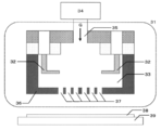
- FIG. 2 is a conceptual diagram of a plasma irradiation head in a plasma jet processing apparatus that can be used in the present invention.
- the plasma generated in the reaction chamber 33 is blown out toward the processing object (sample 38) disposed outside the plasma irradiation head 31, so that a so-called remote type plasma processing apparatus is formed.
- a pair of electrodes 32 and 32 are arranged opposite to each other in the plasma irradiation head 31, and one of the electrodes 32 and 32 is connected to a power source and the other is electrically grounded (power source, ground). If the voltage is supplied from the power source with the gas flowing into the reaction chamber 33, plasma can be generated.
- a processing gas G is introduced from a gas supply device 34 into an inflow path (gas introduction port) 35 to generate plasma (that is, a processing gas converted into plasma).
- the gas is blown out from the gas blow-out port 37 formed on the surface, and sprayed onto the surface of the sample (rubber body containing vulcanized silicone rubber) 38 below the gas blow-out port 37. Since the lower part of the gas outlet 37 is not sealed, the atmosphere flows in, and the oxygen concentration in the vicinity of the sample 38 is higher than the oxygen concentration in the gas G in the vicinity of the inflow path 35.
- the gas G at least one selected from the group consisting of nitrogen and air can be used.
- the distance between the gas outlet 37 and the surface of the sample 38 is preferably 50 mm or less, and more preferably 20 mm or less.
- a desired portion of the sample 38 can be irradiated with plasma.
- the moving speed of the stage 39 is preferably 0.5 to 10 mm / second, but the present invention is not limited to such an example.
- the plasma irradiation time to the sample 38 can be adjusted, for example, by changing the moving speed of the stage 39 or reciprocating the stage 39 a desired number of times.
- thermocompression bonding heating and pressurization
- both can be directly joined.
- the thermocompression bonding may be performed by heating and pressurizing for about 10 to 40 minutes at a heating temperature of 140 to 200 ° C. and a pressure of 1 to 20 MPa, for example.
- a heating temperature 140 to 200 ° C.
- a pressure of 1 to 20 MPa for example.
- what is necessary is just to laminate
- the mechanism by which the resin body and the rubber body are bonded (adhered) and good adhesive strength (bonding strength) is not necessarily clarified, but the peroxide radical introduced to the surface of the resin body by plasma treatment It is considered that the C—OH group or COOH group (carboxyl group) formed due to this and the silanol (Si—OH) group present on the rubber body surface by the plasma treatment are chemically bonded after hydrogen bonding or dehydration condensation reaction. .
- the mechanism for improving the adhesive strength in the present invention is not limited to the above mechanism.
- the adhesive strength between the resin body and the rubber body is preferably 1.0 N / mm or more, more preferably 1.5 N / mm or more, and further preferably 2.0 N / mm or more. A method for measuring the adhesive strength will be described later.
- the AFM-IR device which combines the surface morphology observation function of the atomic force microscope (AFM) and the functional group identification function of infrared spectroscopy (IR), has a very high spatial resolution of about 10 nm, and has surface morphology and elasticity. It is possible to clarify not only the information on the rate but also the distribution of functional groups present on the surface.
- AFM atomic force microscope
- IR infrared spectroscopy
- a bonded body of the present invention for example, a bonded body of a PTFE sheet and a PDMS sheet described in Examples described later, a bonded body of a PFA sheet and a PDMS sheet, a bonded body of an ETFE sheet and a PDMS sheet, an FEP sheet and a PDMS sheet
- the cross section of the bonded body is analyzed using AFM-IR, the surface modification depth and interface roughness by plasma treatment can be specified as well as the material constituting the bonded body, so reverse engineering is possible. is there.
- Example 1-1 A PTFE sheet whose surface was plasma-treated and a PDMS sheet whose surface was plasma-jet-treated were prepared as follows.
- ⁇ PTFE sheet> (I) Cleaning A PTFE sheet (Nitoflon No. 900UL) cut to a thickness of 0.2 mm by Nitto Denko Co., Ltd. was cut into a certain size (width: 4.5 cm x length: 7 cm). did. The resin body was ultrasonically cleaned in acetone for 1 minute, and then ultrasonically cleaned in pure water for 1 minute. Thereafter, the pure water adhering to the PTFE sheet was removed by blowing nitrogen gas (purity: 99% or more) with an air gun.
- nitrogen gas purity: 99% or more
- the high frequency power source of the plasma generator one having an applied voltage frequency of 13.56 MHz was used.
- the electrode an electrode having a structure in which a copper tube having an inner diameter of 1.8 mm, an outer diameter of 3 mm, and a length of 165 mm was covered with an alumina tube having an outer diameter of 5 mm, a thickness of 1 mm, and a length of 145 mm was used.
- a sample holder made of aluminum alloy and having a diameter of 50 mm and a width of 3.4 cm was used.
- a PTFE sheet was placed on the upper surface of the sample holder, and the distance between the resin body surface and the electrode was set to 1.0 mm.
- the chamber was sealed and reduced in pressure to 10 Pa with a rotary pump, and then helium gas was introduced until atmospheric pressure (1013 hPa) was reached. Thereafter, the high-frequency power source is set so that the output power density is 19.1 W / cm 2 , and the scanning stage is moved at a speed of 2 mm / second, and the length that the electrode passes is 30 mm in the length direction of the resin body. Set to move by minutes.
- the high frequency power supply was operated, the scanning stage was moved, and plasma irradiation was performed for 600 seconds within a range of width: 1.0 cm ⁇ length: 3.4 cm.
- the plasma irradiation time was adjusted by the number of reciprocations of 30 mm movement in the length direction of the scanning stage. Further, when the oxygen concentration in the vicinity of the PTFE sheet surface (plasma irradiation region) was measured using a zirconia oxygen concentration meter LC-300 manufactured by Toray Engineering Co., Ltd., it was 25.7 ppm, which is much lower than 0.5% by volume. It was.
- the surface temperature of the resin body during the plasma treatment was 203 ° C. when measured with a radiation thermometer (FT-H40K and FT-50A, manufactured by Keyence Corporation).
- the addition-crosslinked PDMS sheet was ultrasonically cleaned in acetone for 1 minute, and then ultrasonically cleaned in pure water for 1 minute. Thereafter, the pure water adhering to the addition-crosslinked PDMS sheet was removed by blowing nitrogen gas (purity: 99% or more) with an air gun.
- the plasma-treated surface of the PTFE sheet is brought into contact with the plasma-treated surface of the PDMS sheet so that the joining range is 20 mm ⁇ 30 mm, and the unjoined range (grip margin) is 10 mm ⁇ 30 mm. Heating and pressurizing were performed for 10 minutes to produce a joined body of a PTFE sheet and a PDMS sheet.
- Copper foil manufactured by Niraco Co., Ltd., model number: CU-113263, Cu purity: 99.9%, 30 mm ⁇ 25 mm ⁇ thickness 0.05 mm
- the above (IV) plasma jet treatment is different in that the distance between the plasma outlet and the copper foil is 10 mm, the stage moving speed is 0.8 mm / second, and the stage is reciprocated five times. Further, surface modification is not performed even if the copper foil is subjected to plasma jet treatment.
- the copper foil after the plasma jet treatment was bonded in the order of PTFE sheet, PDMS sheet, and copper foil.
- the copper foil was fixed to the upper chuck, the PDMS sheet and the PTFE sheet were sandwiched between the lower chuck, and measured by the T-peeling test, the bond strength between the PDMS sheet and the copper foil was 2.2 N / mm or more.
- attached separately was prepared and the adhesive strength of a PTFE sheet and a PDMS sheet was measured by the said T-shaped peeling test, it was 2.4 N / mm or more.
- the stainless steel foil after the plasma jet treatment was bonded in the order of PTFE sheet, PDMS sheet, and stainless steel foil.
- the stainless steel foil was fixed to the upper chuck, the PDMS sheet and the PTFE sheet were sandwiched between the lower chucks, and measured by the above T-peeling test.
- the adhesive strength was 2.3 N / mm or more.
- attached was prepared separately and the adhesive strength of a PTFE sheet and a PDMS sheet was measured by the said T-shaped peeling test, it was 2.4 N / mm or more.
- ⁇ Adhesive strength between the layers of the three-layer laminate including a glass plate> A glass plate (manufactured by Matsunami Glass Industry Co., Ltd., model number: S7213, 76 mm ⁇ 26 mm ⁇ thickness 1 mm) was adhered to the joined body in the order of PTFE sheet, PDMS sheet, and glass plate. About the laminate to which the glass plate was bonded, the glass plate was fixed, the PDMS sheet and the PTFE sheet were pulled in a 90-degree direction with the chuck interposed therebetween, and the adhesion strength between the PDMS sheet and the glass plate was measured in the same manner. It was 2.0 N / mm or more. Moreover, when the laminated body to which the glass plate was adhere
- the glass-coated ABS resin was bonded to the adhesive body in the order of PTFE sheet, PDMS sheet, and glass-coated ABS resin.
- the glass-coated ABS resin is fixed to the upper chuck, and the PDMS sheet and PTFE sheet are sandwiched between the lower chuck and pulled in the 180 degree direction (up and down).
- the adhesive strength between the sheet and the glass-coated ABS resin was measured, it was 2.0 N / mm or more.
- attached separately was prepared and the adhesive strength of a PTFE sheet and a PDMS sheet was measured by the said T-shaped peeling test, it was 2.4 N / mm or more.
- Example 1 Example 1 except that the surface treatment of the PDMS sheet was changed from (IV) plasma jet treatment to (II) high-temperature plasma treatment, and the surface of the addition-crosslinked PDMS sheet subjected to the cleaning of (III) was modified with plasma.
- a bonded body was prepared in the same manner as in Example 1, and the adhesive strength was measured. The results are shown in Table 1.
- Example 1-2 A bonded body was prepared in the same manner as in Example 1-1 except that the surface treatment of the PDMS sheet was changed from (IV) plasma jet treatment to (V) low temperature plasma treatment described below, and the adhesive strength was measured. The results are shown in Table 1.
- (V) Low-temperature plasma treatment Using a plasma generator (product name: K2X02L023, manufactured by Myeongchang Kiko Co., Ltd.) having the configuration shown in FIG. 1, the surface of the addition cross-linked PDMS sheet subjected to the cleaning of (III) is modified with plasma. Quality.
- a plasma generator product name: K2X02L023, manufactured by Myeongchang Kiko Co., Ltd.
- the high frequency power source of the plasma generator one having an applied voltage frequency of 13.56 MHz was used.
- the electrode an electrode having a structure in which a copper tube having an inner diameter of 1.8 mm, an outer diameter of 3 mm, and a length of 165 mm was covered with an alumina tube having an outer diameter of 5 mm, a thickness of 1 mm, and a length of 145 mm was used.
- a sample holder made of aluminum alloy and having a diameter of 50 mm and a width of 3.4 cm was used.
- a rubber body was placed on the upper surface of the sample holder, and the distance between the rubber body surface and the electrode was set to 1.0 mm.
- the chamber was sealed and reduced in pressure to 10 Pa with a rotary pump, and then helium gas was introduced until atmospheric pressure (1013 hPa) was reached. Thereafter, the high-frequency power source is set so that the output power density is 7.4 W / cm 2 , and the scanning stage is moved at a speed of 2 mm / second and the length that the electrode passes is 30 mm in the length direction of the rubber body. Set to move by minutes.
- the high frequency power supply was operated, the scanning stage was moved, and plasma irradiation was performed for 600 seconds within a range of width: 1.0 cm ⁇ length: 3.4 cm.
- the plasma irradiation time was adjusted by the number of reciprocations of 30 mm movement in the length direction of the scanning stage. Further, the surface temperature of the rubber body during the plasma treatment was measured with a radiation thermometer (FT-H40K and FT-50A, manufactured by Keyence Corporation) and found to be 95 ° C.
- FT-H40K and FT-50A manufactured by Keyence Corporation
- Example 1-3 A bonded body was prepared in the same manner as in Example 1-1 except that the surface treatment of the PTFE sheet was not performed, and the adhesive strength was measured. The results are shown in Table 1.
- Example 1 except that the surface treatment of the PTFE sheet was changed from (II) high-temperature plasma treatment to (IV) plasma jet treatment, and the surface of the PTFE sheet subjected to the cleaning of (I) was modified by plasma jet treatment.
- a bonded body was prepared in the same manner as in Example 1, and the adhesive strength was measured. The results are shown in Table 1.
- Example 1-1 (Comparative Example 1-5) Example 1-1, except that the surface treatment of the PTFE sheet was changed from (II) high-temperature plasma treatment to (V) low-temperature plasma treatment, and the surface of the PTFE sheet subjected to the cleaning of (I) was modified by plasma.
- a bonded body was prepared in the same manner as above, and the adhesive strength was measured. The results are shown in Table 1.
- Comparative Examples 1-6 to 8 In Comparative Examples 1-6 to 8, a joined body was prepared in the same manner as Comparative Example 1-3, Example 1-1, and Comparative Example 1-4, except that the surface treatment of the PDMS sheet was not performed. Prepared and measured the adhesive strength. The results are shown in Table 1.
- Example 2-1 and Comparative Examples 2-1 and 2 Example 1-1 was performed except that the PTFE sheet was replaced with a PFA sheet (Nephron (registered trademark) AF series manufactured by Daikin Industries, Ltd.). A joined body was produced in the same manner as Comparative Example 1-1 and Comparative Example 1-2. The adhesive strength of each of the joined bodies of Example 2-1 and Comparative Examples 2-1 and 2 was measured, and the results are shown in Table 2.
- Example 3-1 and Comparative Examples 3-1 and 2 In Example 3-1, Comparative Example 3-1, and Comparative Example 3-2, Example 1-1 was performed except that the PTFE sheet was replaced with an ETFE sheet (Neoflon (registered trademark) EF series manufactured by Daikin Industries, Ltd.). A joined body was produced in the same manner as Comparative Example 1-1 and Comparative Example 1-2. The adhesive strength of the joined bodies of Example 3-1 and Comparative Examples 3-1 and 2 was measured, and the results are shown in Table 3.
- ETFE sheet Neoflon (registered trademark) EF series manufactured by Daikin Industries, Ltd.
- Example 4-1 and Comparative Example 4-1 are the same as Example 1-1 and Comparative Example 1-1, except that the PTFE sheet was replaced with an FEP sheet (Neoflon (registered trademark) NF series manufactured by Daikin Industries, Ltd.). Similarly, a joined body was produced. With respect to each of the joined bodies of Example 4-1 and Comparative Example 4-1, the above adhesive strength was measured, and the results are shown in Table 4.
- Example 1-1 Various resin bodies (PFFE sheet, PFA sheet, ETFE sheet, FEP sheet) are subjected to the high temperature plasma treatment of (II) above with the oxygen concentration in the plasma irradiation region being less than 0.5% by volume.
- Example 1-1, Example 2-1, Example 3-1, and Example 4-1 in which the plasma jet treatment of the above (IV) was performed with the oxygen concentration in the irradiation region being 1% by volume or more, both adhesive strengths were It was very high at 2.4 N / mm or more.
- comparison was not made by performing the high temperature plasma treatment of (II) above on various resin bodies (PFFE sheet, PFA sheet, ETFE sheet, FEP sheet) and the plasma jet treatment of (IV) above on a PDMS sheet.
- Comparative Examples 2-1 to 2 Comparative Examples 3-1 to 2, and Comparative Example 4-1
- the adhesive strength is significantly lower than 0.1 N / mm, and the joined body easily peels off. It was in a state.
Landscapes
- Chemical & Material Sciences (AREA)
- Medicinal Chemistry (AREA)
- Organic Chemistry (AREA)
- Polymers & Plastics (AREA)
- Health & Medical Sciences (AREA)
- Chemical Kinetics & Catalysis (AREA)
- Materials Engineering (AREA)
- Manufacturing & Machinery (AREA)
- Engineering & Computer Science (AREA)
- Treatments Of Macromolecular Shaped Articles (AREA)
- Manufacture Of Macromolecular Shaped Articles (AREA)
- Laminated Bodies (AREA)
- Lining Or Joining Of Plastics Or The Like (AREA)
Abstract
フッ素系樹脂を含む樹脂体と加硫シリコーンゴムを含むゴム体との接合体。前記加硫シリコーンゴムがジメチルシロキサン単位を含むことが好ましい。加硫シリコーンゴムを含むゴム体の表面に対して、所定のプラズマ処理を行うことによって、フッ素系樹脂を含む樹脂体に上記ゴム体が接合することを見出した。
Description
本発明は、接合体及びその製造方法に関する。
従来より、フッ素系樹脂を含む成型体の表面に各種の機能を付与するために、エッチング処理、紫外線処理、化学蒸着処理、プラズマ処理等が行われている。フッ素系樹脂を用いて成型された成型体は、表面の濡れ性が低く接着剤を用いた接着が困難であるため、エッチング処理やプラズマ処理を行って成型体の表面の接着性を向上させる処理が行われている。
特許文献1には、プラズマ照射を行い、成型体表面にプラズマ中のイオンを注入し、かつ、成型体表面のフッ素原子をフッ素原子以外の原子に置換する表面改質方法が記載されている。特許文献2には、イオン注入処理により、フッ素樹脂の表面改質が行われ、微細突起が形成されたフッ素樹脂成型体が記載されている。特許文献3では、表面にプラズマ-モノマー重合層を有するフッ素樹脂層が開示されており、表面改質とグラフト化が同時に行われていることが記載されている。また、本発明者らが既に出願した特許文献4では、有機高分子化合物を含む成型体の表面温度を、(前記有機高分子化合物の融点-120)℃以上にして、該成型体の表面に大気圧プラズマ処理を行い、過酸化物ラジカルを導入することを特徴とする表面改質成型体の製造方法を開示している。
しかし、上記特許文献1~4に記載の製造方法で作製されたフッ素樹脂層や成型体を用いたとしても、上記フッ素樹脂層や上記成型体と加硫シリコーンゴムとの接着には更なる研究の余地があることがわかった。
本発明の目的は、フッ素系樹脂を含む樹脂体と加硫シリコーンゴムを含むゴム体との接合体を提供することにある。
上記課題に鑑みて、本発明の発明者らは鋭意検討を行った。その結果、加硫シリコーンゴムを含むゴム体の表面に対して、所定のプラズマ処理を行うことによって、フッ素系樹脂を含む樹脂体に上記ゴム体が接着することを見出し、本発明を完成するに至った。本発明の要旨は以下の通りである。
本発明は、フッ素系樹脂を含む樹脂体と加硫シリコーンゴムを含むゴム体との接合体である。
前記加硫シリコーンゴムがジメチルシロキサン単位を含むことが好ましい。
前記フッ素系樹脂が、ヘキサフルオロプロピレン単位、パーフルオロアルキルビニルエーテル単位、メチレン単位、エチレン単位及びパーフルオロジオキソール単位の少なくとも1種とジフルオロメチレン単位との共重合体、又はポリテトラフルオロエチレンであることが好ましい。
前記樹脂体の少なくとも一方の表面及び前記ゴム体の少なくとも一方の表面がプラズマ処理されており、前記プラズマ処理された面同士が接合された接合体であることが好ましい。
前記樹脂体と前記ゴム体との接着強度が1.0N/mm以上であることが好ましい。
加えて、本発明は、フッ素系樹脂を含む樹脂体とシリコーンゴムを含むゴム体との接合体の製造方法も包含しており、上記製造方法は、前記樹脂体の表面近傍の酸素濃度を0.5体積%未満として、前記樹脂体の表面にプラズマ処理を行い、表面改質された樹脂体を製造する工程と、前記ゴム体の表面近傍の酸素濃度を1体積%以上として、前記ゴム体の表面にプラズマ処理を行い、表面改質されたゴム体を製造する工程と、前記表面改質された樹脂体の改質された表面と前記表面改質されたゴム体の改質された表面とを接触させ、加熱及び加圧する工程とを含むことを特徴とする。
加硫シリコーンゴムを含むゴム体の表面に対して、所定のプラズマ処理を行うことにより、フッ素系樹脂を含む樹脂体に上記ゴム体を接着させることができた。
また、加硫シリコーンゴムを含むゴム体の表面には金属やガラスが接着することが知られている。よって、本発明の接合体におけるゴム体の表面に金属やガラスを接着させることにより、樹脂体、ゴム体、金属の順に重ねたり、樹脂体、ゴム体、ガラスの順に重ねたりすることもできる。すなわち、接着剤を用いることなく、フッ素系樹脂を含む樹脂体を金属やガラスに接着させることができる。
本発明の接合体は、フッ素系樹脂を含む樹脂体(以下、単に樹脂体ということがある)と加硫シリコーンゴムを含むゴム体(以下、単にゴム体ということがある)とが接合されたものである。接着剤を用いることなく、樹脂体とゴム体とが直接接合されていることが好ましい。また、樹脂体の少なくとも一方の表面及びゴム体の少なくとも一方の表面がプラズマ処理されており、上記プラズマ処理された面同士が接合されていることが好ましい。なお、本明細書では、フッ素系樹脂とは、分子中にフッ素原子を含む樹脂のことを指す。
<フッ素系樹脂を含む樹脂体>
フッ素系樹脂は、ヘキサフルオロプロピレン単位、パーフルオロアルキルビニルエーテル単位、メチレン単位、エチレン単位及びパーフルオロジオキソール単位の少なくとも1種とジフルオロメチレン単位との共重合体、又はポリテトラフルオロエチレンである。フッ素系樹脂は、ヘキサフルオロプロピレン単位、パーフルオロアルキルビニルエーテル単位、エチレン単位又はパーフルオロジオキソール単位とテトラフルオロエチレン単位との共重合体、又はポリテトラフルオロエチレンであることが好ましい。
フッ素系樹脂としては、ポリテトラフルオロエチレン(PTFE)、ポリクロロトリフルオロエチレン(PCTFE)、ポリビニリデンフルオライド(PVDF)、ポリビニルフルオライド(PVF)、テトラフルオロエチレン-ヘキサフルオロプロピレン共重合体(FEP)、テトラフルオロエチレン-パーフルオロアルキルビニルエーテル共重合体(PFA)、テトラフルオロエチレン-エチレン共重合体(ETFE)、テトラフルオロエチレン-パーフルオロジオキソール共重合体(TFE/PDD)、クロロトリフルオロエチレン-エチレン共重合体(ECTFE)などが挙げられる。このうち、モノマー単位の炭素-フッ素結合数(フッ素原子の置換割合)の観点から、PTFE、PFA、ETFE、FEPの少なくとも1種であることが好ましく、PTFEであることが特に好ましい。フッ素系樹脂は、1種でもよいし、2種以上含んでいてもよい。
フッ素系樹脂は、ヘキサフルオロプロピレン単位、パーフルオロアルキルビニルエーテル単位、メチレン単位、エチレン単位及びパーフルオロジオキソール単位の少なくとも1種とジフルオロメチレン単位との共重合体、又はポリテトラフルオロエチレンである。フッ素系樹脂は、ヘキサフルオロプロピレン単位、パーフルオロアルキルビニルエーテル単位、エチレン単位又はパーフルオロジオキソール単位とテトラフルオロエチレン単位との共重合体、又はポリテトラフルオロエチレンであることが好ましい。
フッ素系樹脂としては、ポリテトラフルオロエチレン(PTFE)、ポリクロロトリフルオロエチレン(PCTFE)、ポリビニリデンフルオライド(PVDF)、ポリビニルフルオライド(PVF)、テトラフルオロエチレン-ヘキサフルオロプロピレン共重合体(FEP)、テトラフルオロエチレン-パーフルオロアルキルビニルエーテル共重合体(PFA)、テトラフルオロエチレン-エチレン共重合体(ETFE)、テトラフルオロエチレン-パーフルオロジオキソール共重合体(TFE/PDD)、クロロトリフルオロエチレン-エチレン共重合体(ECTFE)などが挙げられる。このうち、モノマー単位の炭素-フッ素結合数(フッ素原子の置換割合)の観点から、PTFE、PFA、ETFE、FEPの少なくとも1種であることが好ましく、PTFEであることが特に好ましい。フッ素系樹脂は、1種でもよいし、2種以上含んでいてもよい。
本発明で用いられる樹脂体には、上述のフッ素系樹脂以外の樹脂が含まれていてもよい。フッ素系樹脂以外の樹脂として、例えば、ポリエチレン樹脂、ポリプロピレン樹脂、シクロオレフィン樹脂等のオレフィン系樹脂;ポリエチレンテレフタレート樹脂等のポリエステル系樹脂;ポリイミド系樹脂;スチレン樹脂、シンジオタクチックポリスチレン樹脂等のスチレン系樹脂;芳香族ポリエーテルケトン樹脂、ポリエーテルエーテルケトン樹脂、ポリフェニレンエーテル樹脂等の芳香族ポリエーテルケトン系樹脂;ポリアセタール系樹脂;ポリフェニレンサルファイド系樹脂;ビスマレイミドトリアジン系樹脂;などが挙げられる。本発明で用いられる樹脂体中の全樹脂100質量部中、フッ素系樹脂は50質量部超含まれており、80質量部以上含まれていることが好ましく、90質量部以上含まれていることがより好ましく、95質量部以上含まれていることがさらに好ましく、99質量部以上含まれていることが特に好ましく、100質量部である(フッ素系樹脂のみを含有する)ことが最も好ましい。
本発明で用いることができる樹脂体の形態は、後述するプラズマ照射が可能な形状であれば、特に限定はなく、各種の形状、構造を有するものに適用できる。例えば、平面、曲面、屈曲面等の表面形状を有する、方形状、球形状、薄膜形状等が挙げられるが、これらに限定されない。また、樹脂体は、フッ素系樹脂の特性に応じて、射出成型、溶融押出成型、ペースト押出成型、圧縮成型、切削成型、キャスト成型、含浸成型等各種の成型方法により成型されたものでよい。また、樹脂体は、例えば通常の射出成型体のような樹脂が緻密な連続構造を有しても良いし、多孔質構造を有しても良いし、不織布状でも良いし、その他の構造でも良い。
<加硫シリコーンゴムを含むゴム体>
加硫シリコーンゴムは、シロキサン単位を含むことが好ましく、ジメチルシロキサン単位を含むことがより好ましい。通常、加硫シリコーンゴムはポリシロキサンを加硫(架橋)することによって製造される。ポリシロキサンは、Si-O構造を有するものであれば特に限定されず、例えば、ポリジメチルシロキサン、メチルフェニルポリシロキサン、メチルハイドロジェンポリシロキサン等の鎖状ポリシロキサン、デカメチルシクロペンタシロキサン、ドデカメチルシクロヘキサシロキサン等の環状ポリシロキサンが挙げられるが、これらのポリシロキサンのうち1種を単独で用いてもよいし、2種以上を組み合わせて使用してもよい。ポリシロキサンは鎖状ポリシロキサンを含むことが好ましく、ポリジメチルシロキサン(PDMS)を含むことがより好ましい。
加硫シリコーンゴムは、シロキサン単位を含むことが好ましく、ジメチルシロキサン単位を含むことがより好ましい。通常、加硫シリコーンゴムはポリシロキサンを加硫(架橋)することによって製造される。ポリシロキサンは、Si-O構造を有するものであれば特に限定されず、例えば、ポリジメチルシロキサン、メチルフェニルポリシロキサン、メチルハイドロジェンポリシロキサン等の鎖状ポリシロキサン、デカメチルシクロペンタシロキサン、ドデカメチルシクロヘキサシロキサン等の環状ポリシロキサンが挙げられるが、これらのポリシロキサンのうち1種を単独で用いてもよいし、2種以上を組み合わせて使用してもよい。ポリシロキサンは鎖状ポリシロキサンを含むことが好ましく、ポリジメチルシロキサン(PDMS)を含むことがより好ましい。
本発明で用いられるゴム体には、加硫シリコーンゴム以外のゴムが含まれていてもよい。加硫シリコーンゴム以外のゴムとして、例えば、ブタジエンゴム、イソプレンゴム、ブチルゴム、フッ素ゴム、エチレンプロピレンゴム、ニトリルゴム、天然ゴムなどが挙げられる。ゴム体100質量部中に、加硫シリコーンゴムは50質量部超含まれており、80質量部以上含まれていることが好ましく、90質量部以上含まれていることがより好ましく、95質量部以上含まれていることがさらに好ましく、99質量部以上含まれていることが特に好ましく、100質量部である(加硫シリコーンゴムのみを含有する)ことが最も好ましい。
架橋剤は、ゴム体100質量部中に、1質量部以上であることが好ましく、より好ましくは1.5質量部以上であり、更に好ましくは2質量部以上であり、また10質量部以下であることが好ましく、より好ましくは7質量部以下であり、更に好ましくは5質量部以下であり、特に好ましくは3質量部以下である。
ゴム組成物は、必要に応じて、通常のゴム組成物に配合される加硫促進剤、架橋助剤、強化剤、受酸剤、可塑剤、耐熱防止剤、着色剤などの他の添加剤を含んでいても良い。これら他の添加剤の含有量は、ゴム体100質量部中に、合計で10質量部以下であることが好ましく、より好ましくは7質量部以下であり、更に好ましくは5質量部以下であり、特に好ましくは3質量部以下である。
シリコーンゴムとしては、例えば、信越化学工業株式会社製のKE-571-U、KE-1571-U、KE-951-U、KE-541-U、KE-551-U、KE-561-U、KE-961T-U、KE-1541-U、KE-1551-U、KE-941-U、KE-971T-U等を使用することができる。
シリコーンゴムは架橋剤により架橋される。架橋剤として付加反応架橋剤及び/又は有機過酸化物架橋剤を挙げることができ、付加反応架橋剤を用いて作製された付加加硫シリコーンゴムであることが好ましい。
前記付加反応架橋剤として、例えば、一分子中に二個以上のSiH基(SiH結合)を有する付加反応型の架橋剤として公知のオルガノハイドロジェンポリシロキサンが好適に挙げられる。付加反応架橋剤は1種でもよいし、2種以上含んでいてもよい。付加反応架橋剤の配合量は、通常、シリコーンゴム100質量部に対して0.1~3.0質量部である。
また、前記有機過酸化物架橋剤単独で、シリコーンゴムを架橋させることも可能であるが、付加反応架橋剤の補助架橋剤として併用してもよい。有機過酸化物架橋剤としては、例えば、ベンゾイルパーオキサイド、ビス-2,4-ジクロロベンゾイルパーオキサイド、ジクミルパーオキサイド、ジ-t-ブチルパーオキサイド、2,5-ジメチル-2,5-ビス(t-ブチルパーオキシ)ヘキサン等が挙げられる。有機過酸化物架橋剤の配合量は、通常、シリコーンゴム100質量部に対して0.1~5.0質量部である。有機過酸化物架橋剤は1種でもよいし、2種以上含んでいてもよい。
付加反応架橋剤は、付加反応触媒を併用するのが好ましい。付加反応触媒としては、白金族の金属単体とその化合物であることが好ましいが、シリカ、アルミナ又はシリカゲルのような担体に吸着させた微粒子状白金金属、塩化第二白金、塩化白金酸、塩化白金酸6水塩のアルコール溶液、パラジウム触媒、ロジウム触媒等を用いてもよい。付加反応触媒の配合量は、通常、シリコーンゴム100質量部に対して1ppm~1.0質量部である。付加反応触媒は1種でもよいし、2種以上含んでいてもよい。
<接合体の接着性>
加硫シリコーンゴムを含むゴム体の表面には金属やガラスが接着するため、本発明の接合体のゴム体の表面に金属やガラスを接着させることができる。従って、樹脂体、ゴム体、金属の順に重ねたり、樹脂体、ゴム体、ガラスの順に重ねたりすることができ、接着剤を用いることなく、フッ素系樹脂を含む樹脂体を金属やガラスに接着させることができる。なお、ガラスとしては、樹脂の表面をガラスでコーティングしたものを用いてもよい。
本発明の接合体のゴム体の表面に金属やガラスを接着させた積層体は、樹脂体とゴム体との接着性、ゴム体と金属又はガラスとの接着性が共に優れている。
加硫シリコーンゴムを含むゴム体の表面には金属やガラスが接着するため、本発明の接合体のゴム体の表面に金属やガラスを接着させることができる。従って、樹脂体、ゴム体、金属の順に重ねたり、樹脂体、ゴム体、ガラスの順に重ねたりすることができ、接着剤を用いることなく、フッ素系樹脂を含む樹脂体を金属やガラスに接着させることができる。なお、ガラスとしては、樹脂の表面をガラスでコーティングしたものを用いてもよい。
本発明の接合体のゴム体の表面に金属やガラスを接着させた積層体は、樹脂体とゴム体との接着性、ゴム体と金属又はガラスとの接着性が共に優れている。
<接合体の製造方法>
以下、フッ素系樹脂を含む樹脂体と加硫シリコーンゴムを含むゴム体との接合体の製造方法の一例について説明するが、以下に記載の製造方法に限定されるものではない。
以下、フッ素系樹脂を含む樹脂体と加硫シリコーンゴムを含むゴム体との接合体の製造方法の一例について説明するが、以下に記載の製造方法に限定されるものではない。
1.フッ素系樹脂を含む樹脂体の表面改質工程
フッ素系樹脂を含む樹脂体の表面近傍に極力酸素が存在しない状態で、樹脂体の表面にプラズマ処理を行い、樹脂体表面に過酸化物ラジカルを十分に形成させることにより、樹脂体の表面改質を行う。具体的には、樹脂体の表面近傍(プラズマ照射領域)の酸素濃度を0.5体積%未満として、樹脂体の表面にプラズマ処理を行い、表面改質された樹脂体を製造すればよい。プラズマ処理については、例えば、樹脂体の表面温度を高めた状態で大気圧プラズマによる処理を行うことで、樹脂体の表面改質を行ってもよい。大気圧プラズマ処理を行うことで、プラズマ中に含まれるラジカル、電子、イオン等により、樹脂体表面の脱フッ素によるダングリングボンドの形成を誘起する。その後、大気に数分から10分程度曝すことによって、大気中の水成分と反応して、ダングリングボンドに過酸化物ラジカルをはじめ、水酸基、カルボニル基などの親水性官能基が自発的に形成される。
樹脂体の表面に対して、表面温度が(フッ素系樹脂の融点-150)℃以上の温度で、大気圧プラズマによる処理を行うことで、樹脂体の表面改質を行うことが好ましい。このような表面温度にすることで、プラズマ照射の対象となる樹脂体表面の高分子化合物の高分子の運動性が高まることになる。そして、このような運動性の高い状態の高分子化合物にプラズマを照射すると、高分子化合物の炭素原子と炭素原子やそれ以外の原子との間の結合が切断された時に、各高分子内の結合が切断された炭素原子同士が架橋反応し、樹脂体表面に過酸化物ラジカルを十分に形成させることができる。特に樹脂体を構成するフッ素系樹脂がPTFEであるときに、樹脂体の表面温度を前記範囲とすることが好ましく、180℃以上であることがより好ましく、200℃以上であることがさらに好ましい。樹脂体の表面温度の上限は特に限定されないが、例えば(融点+20)℃以下とすれば良い。
フッ素系樹脂を含む樹脂体の表面近傍に極力酸素が存在しない状態で、樹脂体の表面にプラズマ処理を行い、樹脂体表面に過酸化物ラジカルを十分に形成させることにより、樹脂体の表面改質を行う。具体的には、樹脂体の表面近傍(プラズマ照射領域)の酸素濃度を0.5体積%未満として、樹脂体の表面にプラズマ処理を行い、表面改質された樹脂体を製造すればよい。プラズマ処理については、例えば、樹脂体の表面温度を高めた状態で大気圧プラズマによる処理を行うことで、樹脂体の表面改質を行ってもよい。大気圧プラズマ処理を行うことで、プラズマ中に含まれるラジカル、電子、イオン等により、樹脂体表面の脱フッ素によるダングリングボンドの形成を誘起する。その後、大気に数分から10分程度曝すことによって、大気中の水成分と反応して、ダングリングボンドに過酸化物ラジカルをはじめ、水酸基、カルボニル基などの親水性官能基が自発的に形成される。
樹脂体の表面に対して、表面温度が(フッ素系樹脂の融点-150)℃以上の温度で、大気圧プラズマによる処理を行うことで、樹脂体の表面改質を行うことが好ましい。このような表面温度にすることで、プラズマ照射の対象となる樹脂体表面の高分子化合物の高分子の運動性が高まることになる。そして、このような運動性の高い状態の高分子化合物にプラズマを照射すると、高分子化合物の炭素原子と炭素原子やそれ以外の原子との間の結合が切断された時に、各高分子内の結合が切断された炭素原子同士が架橋反応し、樹脂体表面に過酸化物ラジカルを十分に形成させることができる。特に樹脂体を構成するフッ素系樹脂がPTFEであるときに、樹脂体の表面温度を前記範囲とすることが好ましく、180℃以上であることがより好ましく、200℃以上であることがさらに好ましい。樹脂体の表面温度の上限は特に限定されないが、例えば(融点+20)℃以下とすれば良い。
本発明では、大気圧プラズマにより、フッ素系樹脂を含む樹脂体の表面を改質する。この大気圧プラズマによる処理の条件は、樹脂体の表面温度及び出力電力密度を上記所定の範囲内とすることができれば、特に限定はない。プラズマによる樹脂体の表面改質を行う技術分野において採用される、大気圧プラズマを発生させることが可能な条件を適宜採用することができる。
もっとも、本発明では、樹脂体の表面温度を、樹脂体表面のフッ素系樹脂の高分子の運動性を高めることが可能な所定の温度範囲にしつつ、大気圧プラズマによる処理を行うため、大気圧プラズマ処理による加熱効果のみにより表面温度を上昇させる場合は、加熱効果が得られる条件で、大気圧プラズマ処理を行うのが好ましい。
もっとも、本発明では、樹脂体の表面温度を、樹脂体表面のフッ素系樹脂の高分子の運動性を高めることが可能な所定の温度範囲にしつつ、大気圧プラズマによる処理を行うため、大気圧プラズマ処理による加熱効果のみにより表面温度を上昇させる場合は、加熱効果が得られる条件で、大気圧プラズマ処理を行うのが好ましい。
大気圧プラズマの発生には、例えば、印加電圧の周波数が50Hz~2.45GHzの高周波電源を用いるとよい。プラズマ発生装置や樹脂体の構成材料等によるため一概にはいえないが、例えば、出力電力密度(単位面積当たりの出力電力)を15W/cm2以上とすれば良く、上限は特に限定されないが、例えば40W/cm2以下であっても良い。
また、パルス出力を使用する場合は、1~50kHzのパルス変調周波数(好ましくは5~30kHz)、5~99%のパルスデューティ(好ましくは15~80%、より好ましくは25~70%)とするとよい。対向電極には、少なくとも片側が誘電体で被覆された円筒状又は平板状の金属を用いることができる。対向させた電極間の距離は、他の条件にもよるが、プラズマの発生と加熱の観点からは、5mm以下が好ましく、より好ましくは3mm以下、更に好ましくは2mm以下、特に好ましくは1mm以下である。対向させた電極間の距離の下限は特に限定されないが、例えば0.5mm以上である。
また、パルス出力を使用する場合は、1~50kHzのパルス変調周波数(好ましくは5~30kHz)、5~99%のパルスデューティ(好ましくは15~80%、より好ましくは25~70%)とするとよい。対向電極には、少なくとも片側が誘電体で被覆された円筒状又は平板状の金属を用いることができる。対向させた電極間の距離は、他の条件にもよるが、プラズマの発生と加熱の観点からは、5mm以下が好ましく、より好ましくは3mm以下、更に好ましくは2mm以下、特に好ましくは1mm以下である。対向させた電極間の距離の下限は特に限定されないが、例えば0.5mm以上である。
プラズマを発生させるために用いるガスとしては、例えば、ヘリウム、アルゴン、ネオンなどの希ガス、酸素、窒素、水素などの反応性ガスを用いることができる。即ち、本発明で用いるガスとしては、非重合性ガスのみを用いるのが好ましい。
また、これらのガスは、1種又は2種以上の希ガスのみを用いても良いし、1種又は2種以上の希ガスと適量の1種又は2種以上の反応性ガスの混合ガスを用いてもよい。
プラズマの発生は、チャンバーを用いて上述のガス雰囲気を制御した条件で行ってもよいし、例えば希ガスを電極部にフローさせる形態をとる完全大気開放条件で行ってもよい。
また、これらのガスは、1種又は2種以上の希ガスのみを用いても良いし、1種又は2種以上の希ガスと適量の1種又は2種以上の反応性ガスの混合ガスを用いてもよい。
プラズマの発生は、チャンバーを用いて上述のガス雰囲気を制御した条件で行ってもよいし、例えば希ガスを電極部にフローさせる形態をとる完全大気開放条件で行ってもよい。
なお、本発明では、樹脂体の、プラズマ照射面と反対側の面には、プラズマ処理の影響はほとんどない(プラズマ照射面よりも硬さ向上等の影響が小さい)ため、フッ素系樹脂が元来有する諸特性(例えば、耐薬品性、耐候性、耐熱性、電気絶縁性など)は損なわれることなく、十分に発揮される。
以下では、本発明で用いられる樹脂体の製造方法に適用可能な大気圧プラズマ処理の実施形態の一例を、主に、樹脂体がPTFE製のシート形状(厚さ:0.2mm)である場合を例にして、図を参照しつつ説明するが、本発明はこうした例に何ら限定されるものではなく、本発明の要旨を逸脱しない範囲において種々の形態で実施し得ることは勿論である。
図1は、本発明において使用可能な大気圧プラズマ処理装置の一例である容量結合型大気圧プラズマ処理装置の概念図を示したものである。図1(a)に示す大気圧プラズマ処理装置Aは、高周波電源10、マッチングユニット11、チャンバー12、真空排気系13、電極14、電極昇降機構15、接地された円柱型回転ステージおよび試料ホルダー16、回転ステージ制御部(図示せず)から構成されている。回転ステージ16は、電極14と対向するように配置されている。円柱型回転ステージおよび試料ホルダー16としては、例えばアルミ合金製のものを用いることができる。電極14としては、図1(b)に示すように、棒状の形状を有し、例えば銅製の内管18の表面を、例えば酸化アルミニウム(Al2O3)の外管19で被覆した構造を有するものを用いることができる。
図1に示す大気圧プラズマ処理装置Aを用いた樹脂体の表面改質方法は以下のとおりである。先ず、樹脂体を必要に応じてアセトン等の有機溶媒や超純水等の水で洗浄した後、図1(a)に示すように、チャンバー12内の試料ホルダー16にシート形状の試料(フッ素樹脂を含む樹脂体)20を配置した後、図示しない吸引装置により、真空排気系13からチャンバー12内の空気を吸引して減圧し、プラズマを発生させるガスをチャンバー12内に供給し(図1(a)矢印参照)、チャンバー12内を大気圧にする。尚、大気圧とは、厳密に1013hPaである必要はなく、700~1300hPaの範囲であればよい。
図1(a)のような装置であれば、樹脂体の表面近傍(プラズマ照射領域)の酸素濃度を0.5体積%未満として、プラズマ処理を行うことができる。
次に、電極昇降機構15の高さ(図1(a)の上下方向)を調整し、電極14を所望の位置に移動させる。電極昇降機構15の高さを調整することで、電極14と試料20の表面(上面)との距離を調整することができる。電極14と試料20表面間の距離は、5mm以下が好ましく、2mm以下がより好ましい。特に、プラズマ処理による自然昇温により、樹脂体表面温度を特定の範囲にする場合は、その距離は1.0mm以下であるのが特に好ましい。尚、試料20を回転ステージ16の回転により移動させるため、電極14と試料20を接触させてはならないのは勿論のことである。
また、回転ステージ16を回転させることで、樹脂体表面の所望の部分にプラズマを照射することができる。例えば、回転ステージ16の回転速度は、1~3mm/秒が好ましいが、本発明はこうした例に何ら限定されるものではない。尚、試料20へのプラズマ照射時間は、例えば、回転ステージ16の回転速度を可変させることや回転ステージ16を所望回数反復回転させることで調整することができる。
また、回転ステージ16を回転させることで、樹脂体表面の所望の部分にプラズマを照射することができる。例えば、回転ステージ16の回転速度は、1~3mm/秒が好ましいが、本発明はこうした例に何ら限定されるものではない。尚、試料20へのプラズマ照射時間は、例えば、回転ステージ16の回転速度を可変させることや回転ステージ16を所望回数反復回転させることで調整することができる。
回転ステージ16を移動させることで試料20を移動させつつ、高周波電源10を作動させることで、電極14と回転ステージ16との間にプラズマを発生させ、試料20の表面の所望の範囲にプラズマを照射する。この時、高周波電源10として、例えば上述のような印加電圧の周波数や出力電力密度のものを用い、例えばアルミナ被覆銅製電極とアルミ合金製試料ホルダーを用いることで、誘電体バリア放電条件下でのグロー放電を実現することができる。そのため、樹脂体表面に安定して過酸化物ラジカルを生成させることができる。過酸化物ラジカルの導入は、プラズマ中に含まれるラジカル、電子、イオン等により、PTFEシート表面の脱フッ素によるダングリングボンドの形成が誘起され、チャンバー内に残存していた空気あるいはプラズマ処理後に清浄な空気にさらすことで空気中の水成分等と反応することで行われる。また、ダングリングボンドには、過酸化物ラジカルの他、水酸基、カルボニル基などの親水性官能基が自発的に形成され得る。
樹脂体表面に照射するプラズマの強度は、上述の高周波電源の各種パラメータ、電極14と樹脂体表面間の距離等により、適宜調整することができる。なお、上記した大気プラズマ発生の好ましい条件(印加電圧の周波数、出力電力密度、パルス変調周波数、パルスデューティ等)は、特に樹脂体がPTFE製のシート形状である場合について有効である。また、出力電力密度に応じて、樹脂体表面に対する積算の照射時間を調整することで、樹脂体表面を特定の温度範囲にすることも可能である。例えば、印加電圧の周波数が5~30MHz、電極14と樹脂体表面間の距離が0.5~2.0mm、出力電力密度が15~30W/cm2である場合、樹脂体表面に対する積算の照射時間を50秒~3300秒とするのが好ましく、250秒~3300秒とするのがより好ましく、550秒~2400秒とするのが特に好ましい。特にPTFE製のシート形状の樹脂体の表面温度を210~327℃とし、照射時間を600~1200秒とすることが好ましい。照射時間が長い場合は、加熱による影響が表れる傾向にある。なお、プラズマ照射時間とは、樹脂体表面にプラズマが照射されている積算時間を意味し、プラズマ照射時間の少なくとも一部で樹脂体表面温度が(融点-150)℃以上となっていれば良く、例えばプラズマ照射時間のうちの1/2以上(好ましくは2/3以上)で樹脂体表面温度が(融点-150)℃以上となっていれば良い。いずれの態様においても、樹脂体の表面温度を上記範囲とすることで、樹脂体表面のPTFE分子の運動性を向上させ、プラズマにより切断されたPTFE分子の炭素-フッ素結合のうちの炭素原子が、同様にして生じた他のPTFE分子の炭素原子と結合して炭素-炭素結合が生じる確率が格段に向上し、表面硬さを向上させることができる。
また、試料20を加熱するための加熱手段を別途設けることができる。図1(b)に示すように樹脂体の表面を直接加熱するためにハロゲンヒーター17などの熱線照射装置を電極14の近傍部に配置してもよいし、チャンバー12内の環境温度を昇温するために、チャンバー12内の上述のガスを加熱する加熱装置と、加熱されたガスをチャンバー12内に循環させる撹拌翼等を備えた循環装置をチャンバー12内に配置してもよいし、試料20を下面側から加熱するために、回転ステージ16に加熱手段を配置してもよいし、これらを組み合わせてもよい。加熱手段による加熱温度は、樹脂体を構成するフッ素系樹脂の特性、成型体の形状、プラズマ処理による加熱効果等を考慮して、適宜設定、制御するとよい。また、プラズマ照射時に所望の温度になるように、高周波電源10を作動させる前に、成型体を予備加熱しておくのが好ましい。
また、プラズマ処理時の成型体の表面温度は、図1(b)に示すように放射温度計21を用いたり、温度測定シールを用いたりすることによって測定することができる。
2.加硫シリコーンゴムを含むゴム体の表面改質工程
加硫シリコーンゴムを含むゴム体の表面に対して、ゴム体の表面近傍(プラズマ照射領域)の酸素濃度を1体積%以上としてプラズマ処理を行い、表面改質されたゴム体を製造する。ゴム体の表面近傍の酸素濃度は3体積%以上とすることがより好ましく、5体積%以上とすることがさらに好ましく、7体積%以上とすることが特に好ましく、10体積%以上とすることが最も好ましい。また、加硫シリコーンゴムを含むゴム体の表面に対するプラズマ処理については、ゴム体の表面近傍の酸素濃度が上記の条件を満たすようなプラズマ処理が行われていれば処理方法は特に限定されないが、プラズマジェット処理であることが好ましい。
加硫シリコーンゴムを含むゴム体の表面に対して、ゴム体の表面近傍(プラズマ照射領域)の酸素濃度を1体積%以上としてプラズマ処理を行い、表面改質されたゴム体を製造する。ゴム体の表面近傍の酸素濃度は3体積%以上とすることがより好ましく、5体積%以上とすることがさらに好ましく、7体積%以上とすることが特に好ましく、10体積%以上とすることが最も好ましい。また、加硫シリコーンゴムを含むゴム体の表面に対するプラズマ処理については、ゴム体の表面近傍の酸素濃度が上記の条件を満たすようなプラズマ処理が行われていれば処理方法は特に限定されないが、プラズマジェット処理であることが好ましい。
以下では、本発明で用いられるゴム体の製造方法に適用可能なプラズマジェット処理の実施形態の一例を、図を参照しつつ説明するが、本発明はこうした例に何ら限定されるものではなく、本発明の要旨を逸脱しない範囲において種々の形態で実施し得ることは勿論である。
図2は、本発明において使用可能なプラズマジェット処理装置におけるプラズマ照射ヘッドの概念図を示したものである。プラズマ照射ヘッド31では、反応室33内で生成したプラズマを、プラズマ照射ヘッド31の外に配された処理対象物(試料38)に向けて吹き出しており、いわゆるリモート式のプラズマ処理装置となっている。プラズマ照射ヘッド31には一対の電極32、32が相対向して配置されており、両電極32、32のうちの一方が電源に接続され、他方が電気的に接地されており(電源、接地は図示せず)、反応室33内にガスを流入させた状態で電源から電圧を供給すればプラズマの生成が可能となる。プラズマ照射ヘッド31においては、ガス供給装置34から流入路(ガス導入口)35に処理用のガスGを導入してプラズマ(即ちプラズマ化された処理用ガス)を生成し、そのプラズマを躯体36に形成されたガス吹き出し口37から吹き出し、ガス吹き出し口37の下方にある試料(加硫シリコーンゴムを含むゴム体)38の表面に吹き付けるようにしている。ガス吹き出し口37の下方は密閉されていないため、大気が流入しており、試料38近傍の酸素濃度は流入路35近傍のガスG中の酸素濃度に比べて高くなっている。ガスGとしては、窒素及び空気からなる群から選択される少なくとも1種を用いることができる。また、ガス吹き出し口37と試料38表面間の距離は、50mm以下が好ましく、20mm以下がより好ましい。
ステージ39を上下左右に移動させることにより、試料38の所望の部分にプラズマを照射することができる。例えば、ステージ39の移動速度は、0.5~10mm/秒が好ましいが、本発明はこうした例に何ら限定されるものではない。尚、試料38へのプラズマ照射時間は、例えば、ステージ39の移動速度を可変させることやステージ39を所望回数往復させることで調整することができる。
ステージ39を上下左右に移動させることにより、試料38の所望の部分にプラズマを照射することができる。例えば、ステージ39の移動速度は、0.5~10mm/秒が好ましいが、本発明はこうした例に何ら限定されるものではない。尚、試料38へのプラズマ照射時間は、例えば、ステージ39の移動速度を可変させることやステージ39を所望回数往復させることで調整することができる。
3.樹脂体とゴム体の接触及び接着工程
表面改質された樹脂体と表面改質されたゴム体とを金型に入れて、表面改質された樹脂体の改質された表面と表面改質されたゴム体の改質された表面とを接触させた状態で熱圧着(加熱及び加圧)すると、両者を直接接合できる。これにより、樹脂体とゴム体との接合体が得られる。熱圧着は、加熱温度を例えば140~200℃、圧力を例えば1~20MPaとして、10~40分間程度加熱及び加圧処理すればよい。尚、両者がシート状の形状である場合は、積層して圧縮成型すればよい。
表面改質された樹脂体と表面改質されたゴム体とを金型に入れて、表面改質された樹脂体の改質された表面と表面改質されたゴム体の改質された表面とを接触させた状態で熱圧着(加熱及び加圧)すると、両者を直接接合できる。これにより、樹脂体とゴム体との接合体が得られる。熱圧着は、加熱温度を例えば140~200℃、圧力を例えば1~20MPaとして、10~40分間程度加熱及び加圧処理すればよい。尚、両者がシート状の形状である場合は、積層して圧縮成型すればよい。
樹脂体とゴム体とが接合(接着)し、良好な接着強度(接合強度)が実現できるメカニズムは必ずしも明らかになったわけではないが、プラズマ処理によって樹脂体表面に導入された過酸化物ラジカルに起因して形成したC-OH基又はCOOH基(カルボキシル基)と、プラズマ処理によってゴム体表面に存在するシラノール(Si-OH)基が水素結合又は脱水縮合反応後に化学結合することなどが考えられる。但し、本発明における接着強度向上のメカニズムは上記メカニズムに限定されない。
樹脂体とゴム体との接着強度が1.0N/mm以上であることが好ましく、1.5N/mm以上であることがより好ましく、2.0N/mm以上であることがさらに好ましい。接着強度の測定方法については後述する。
原子間力顕微鏡(AFM)の表面形態観察機能と赤外分光法(IR)の官能基特定機能を組み合わせたAFM-IRという装置は、10nm程度の非常に高い空間分解能を持ち、表面形態や弾性率に関する情報だけでなく、表面に存在する官能基の分布も明らかにすることが可能である。本発明の接合体(例えば、後述の実施例に記載のPTFEシートとPDMSシートとの接合体、PFAシートとPDMSシートとの接合体、ETFEシートとPDMSシートとの接合体、FEPシートとPDMSシートとの接合体など)の断面をAFM-IRを用いて分析すれば、接合体を構成する材料の特定はもちろんプラズマ処理による表面改質深さや界面粗さを特定できるため、リバースエンジニアリングが可能である。
本願は、2018年5月31日に出願された日本国特許出願第2018-105432号に基づく優先権の利益を主張するものである。2018年5月31日に出願された日本国特許出願第2018-105432号の明細書の全内容が、本願に参考のため援用される。
以下、実施例を挙げて本発明をより具体的に説明する。本発明は以下の実施例によって制限を受けるものではなく、前記、後記の趣旨に適合し得る範囲で適当に変更を加えて実施することも勿論可能であり、それらはいずれも本発明の技術的範囲に包含される。
(実施例1-1)
以下のようにして、表面をプラズマ処理したPTFEシートと表面をプラズマジェット処理したPDMSシートをそれぞれ作製した。
以下のようにして、表面をプラズマ処理したPTFEシートと表面をプラズマジェット処理したPDMSシートをそれぞれ作製した。
<PTFEシート>
(I)洗浄
日東電工株式会社にて厚さ0.2mmに切削されたPTFEシート(ニトフロンNo.900UL)を一定の大きさ(幅:4.5cm×長さ:7cm)に切り分けたものを準備した。この樹脂体をアセトン中で1分間超音波洗浄した後、純水中で1分間超音波洗浄した。その後、PTFEシートに付着した純水は、エアガンにより窒素ガス(純度:99%以上)を吹付け除去した。
(I)洗浄
日東電工株式会社にて厚さ0.2mmに切削されたPTFEシート(ニトフロンNo.900UL)を一定の大きさ(幅:4.5cm×長さ:7cm)に切り分けたものを準備した。この樹脂体をアセトン中で1分間超音波洗浄した後、純水中で1分間超音波洗浄した。その後、PTFEシートに付着した純水は、エアガンにより窒素ガス(純度:99%以上)を吹付け除去した。
(II)高温プラズマ処理
図1に示す構成を有するプラズマ発生装置(明昌機工株式会社製、製品名K2X02L023)を用いて、上記(I)の洗浄を行ったPTFEシートの表面をプラズマにより改質した。
プラズマ発生装置の高周波電源として、印加電圧の周波数が13.56MHzのものを用いた。電極としては、内径1.8mm、外径3mm、長さ165mmの銅管を外径5mm、厚さ1mm、長さ145mmのアルミナ管で被覆した構造のものを用いた。試料ホルダーとしては、アルミ合金製で直径:50mm、幅:3.4cmの円柱状のものを用いた。試料ホルダーの上面に、PTFEシートを載せ、樹脂体表面と電極との距離が1.0mmになるように設定した。
チャンバーを密閉し、ロータリーポンプにより10Paになるまで減圧した後、大気圧(1013hPa)になるまでヘリウムガスを導入した。その後、出力電力密度が19.1W/cm2になるように高周波電源を設定するとともに、走査ステージを、移動速度が2mm/秒で、電極が通過する長さが樹脂体の長さ方向に30mm分移動するように設定した。その後、高周波電源を作動させ、走査ステージを移動させ、幅:1.0cm×長さ:3.4cmの範囲内で600秒間プラズマ照射を行った。プラズマの照射時間は、走査ステージの長さ方向への30mmの移動を往復させる回数で調整した。また、PTFEシート表面近傍(プラズマ照射領域)における酸素濃度を東レエンジニアリング株式会社製ジルコニア式酸素濃度計LC-300を用いて測定したところ、25.7ppmであり、0.5体積%を大きく下回っていた。そして、プラズマ処理時の樹脂体の表面温度を、放射温度計(FT-H40KおよびFT-50A、株式会社キーエンス製)により測定したところ、203℃であった。
図1に示す構成を有するプラズマ発生装置(明昌機工株式会社製、製品名K2X02L023)を用いて、上記(I)の洗浄を行ったPTFEシートの表面をプラズマにより改質した。
プラズマ発生装置の高周波電源として、印加電圧の周波数が13.56MHzのものを用いた。電極としては、内径1.8mm、外径3mm、長さ165mmの銅管を外径5mm、厚さ1mm、長さ145mmのアルミナ管で被覆した構造のものを用いた。試料ホルダーとしては、アルミ合金製で直径:50mm、幅:3.4cmの円柱状のものを用いた。試料ホルダーの上面に、PTFEシートを載せ、樹脂体表面と電極との距離が1.0mmになるように設定した。
チャンバーを密閉し、ロータリーポンプにより10Paになるまで減圧した後、大気圧(1013hPa)になるまでヘリウムガスを導入した。その後、出力電力密度が19.1W/cm2になるように高周波電源を設定するとともに、走査ステージを、移動速度が2mm/秒で、電極が通過する長さが樹脂体の長さ方向に30mm分移動するように設定した。その後、高周波電源を作動させ、走査ステージを移動させ、幅:1.0cm×長さ:3.4cmの範囲内で600秒間プラズマ照射を行った。プラズマの照射時間は、走査ステージの長さ方向への30mmの移動を往復させる回数で調整した。また、PTFEシート表面近傍(プラズマ照射領域)における酸素濃度を東レエンジニアリング株式会社製ジルコニア式酸素濃度計LC-300を用いて測定したところ、25.7ppmであり、0.5体積%を大きく下回っていた。そして、プラズマ処理時の樹脂体の表面温度を、放射温度計(FT-H40KおよびFT-50A、株式会社キーエンス製)により測定したところ、203℃であった。
<PDMSシート>
(III)準備
株式会社ハタダにて、付加加硫シリコーンゴムである信越化学工業株式会社製信越シリコーン(登録商標)KE-541-U(商品名)100質量部に、加硫剤である信越化学工業株式会社製C-25Bを2質量部、白金触媒である信越化学工業株式会社製C-25Aを0.5質量部配合して付加架橋を行い、付加架橋PDMSシートを成型した。上記付加架橋PDMSシートをアセトン中で1分間超音波洗浄した後、純水中で1分間超音波洗浄した。その後、付加架橋PDMSシートに付着した純水は、エアガンにより窒素ガス(純度:99%以上)を吹付け除去した。
(III)準備
株式会社ハタダにて、付加加硫シリコーンゴムである信越化学工業株式会社製信越シリコーン(登録商標)KE-541-U(商品名)100質量部に、加硫剤である信越化学工業株式会社製C-25Bを2質量部、白金触媒である信越化学工業株式会社製C-25Aを0.5質量部配合して付加架橋を行い、付加架橋PDMSシートを成型した。上記付加架橋PDMSシートをアセトン中で1分間超音波洗浄した後、純水中で1分間超音波洗浄した。その後、付加架橋PDMSシートに付着した純水は、エアガンにより窒素ガス(純度:99%以上)を吹付け除去した。
(IV)プラズマジェット処理
図2に示す構成を有する超高密度大気圧プラズマユニット(株式会社FUJI製Tough Plasma FPE20)を用いて、上記(III)の洗浄を行った付加架橋PDMSシートの表面をプラズマジェット処理により改質した。
プラズマ照射領域への窒素ガスの流量を29.7L/min、空気の流量を0.3L/minとし、すなわち窒素ガス及び空気の合計流量を100%とすると空気の割合が1.0%、酸素の割合が0.2%となるようにしたが、密閉式の装置ではなく、PDMSシートの近傍には大気が流入しているため、プラズマ照射領域における酸素濃度を東レエンジニアリング株式会社製ジルコニア式酸素濃度計LC-300を用いて測定したところ11.3%であった。プラズマ吹き出し口と付加架橋PDMSシートとの距離を10mmとし、ステージの移動速度を8mm/秒とし、ステージを往復させることなく1回だけプラズマジェット処理した。
図2に示す構成を有する超高密度大気圧プラズマユニット(株式会社FUJI製Tough Plasma FPE20)を用いて、上記(III)の洗浄を行った付加架橋PDMSシートの表面をプラズマジェット処理により改質した。
プラズマ照射領域への窒素ガスの流量を29.7L/min、空気の流量を0.3L/minとし、すなわち窒素ガス及び空気の合計流量を100%とすると空気の割合が1.0%、酸素の割合が0.2%となるようにしたが、密閉式の装置ではなく、PDMSシートの近傍には大気が流入しているため、プラズマ照射領域における酸素濃度を東レエンジニアリング株式会社製ジルコニア式酸素濃度計LC-300を用いて測定したところ11.3%であった。プラズマ吹き出し口と付加架橋PDMSシートとの距離を10mmとし、ステージの移動速度を8mm/秒とし、ステージを往復させることなく1回だけプラズマジェット処理した。
PTFEシートのプラズマ処理した表面とPDMSシートのプラズマ処理した表面とを接触させ、接合範囲が20mm×30mm、未接合範囲(掴みしろ)が10mm×30mmとなるように、温度180℃、圧力10MPaで10分間、加熱及び加圧処理し、PTFEシートとPDMSシートとの接合体を作製した。
デジタルフォースゲージ(ZP-200N,株式会社イマダ製作所製)と電動スタンド(MX-500N,株式会社イマダ製作所製)を組み合わせて用いて、掴みしろをチャックにはさみ、PTFEシートとPDMSシートとを180度の方向に引張り、T字はく離試験を行い、PTFEシートとPDMSシートとの接着強度を測定した。ロードセルは1kN、引張速度は60mm/minとした。その結果を表1に示す。なお、表1に記載の接着強度は試験期間中の最大値である。
<銅箔を備えた3層積層体の各層間の接着強度>
銅箔(ニラコ株式会社製、型番:CU-113263、Cu純度:99.9%、30mm×25mm×厚さ0.05mm)を上記(IV)プラズマジェット処理に記載の方法で洗浄した。ただし、上記(IV)プラズマジェット処理とは、プラズマ吹き出し口と銅箔との距離を10mmとし、ステージの移動速度を0.8mm/秒とし、ステージを5往復させた点で異なる。また、銅箔をプラズマジェット処理しても表面改質は行われない。プラズマジェット処理後の銅箔を、PTFEシート、PDMSシート、銅箔の順となるように接着した。銅箔が接着された積層体について、銅箔を上チャックに固定し、PDMSシートとPTFEシートを下チャックにはさみ、上記T字はく離試験で測定したところ、PDMSシートと銅箔との接着強度は、2.2N/mm以上であった。また、銅箔が接着された積層体を別に用意し、PTFEシートとPDMSシートとの接着強度を上記T字はく離試験で測定したところ、2.4N/mm以上であった。
銅箔(ニラコ株式会社製、型番:CU-113263、Cu純度:99.9%、30mm×25mm×厚さ0.05mm)を上記(IV)プラズマジェット処理に記載の方法で洗浄した。ただし、上記(IV)プラズマジェット処理とは、プラズマ吹き出し口と銅箔との距離を10mmとし、ステージの移動速度を0.8mm/秒とし、ステージを5往復させた点で異なる。また、銅箔をプラズマジェット処理しても表面改質は行われない。プラズマジェット処理後の銅箔を、PTFEシート、PDMSシート、銅箔の順となるように接着した。銅箔が接着された積層体について、銅箔を上チャックに固定し、PDMSシートとPTFEシートを下チャックにはさみ、上記T字はく離試験で測定したところ、PDMSシートと銅箔との接着強度は、2.2N/mm以上であった。また、銅箔が接着された積層体を別に用意し、PTFEシートとPDMSシートとの接着強度を上記T字はく離試験で測定したところ、2.4N/mm以上であった。
<ステンレス鋼箔を備えた3層積層体の各層間の接着強度>
ステンレス鋼箔(株式会社岩田製作所製、型番:TS200-200-005、種類:SUS304、30mm×25mm×厚さ0.05mm)を上記(IV)プラズマジェット処理に記載の方法で洗浄した。ただし、上記(IV)プラズマジェット処理とは、プラズマ吹き出し口とステンレス鋼箔との距離を10mmとし、ステージの移動速度を0.8mm/秒とし、ステージを5往復させた点で異なる。また、ステンレス鋼箔をプラズマジェット処理しても表面改質は行われない。プラズマジェット処理後のステンレス鋼箔を、PTFEシート、PDMSシート、ステンレス鋼箔の順となるように接着した。ステンレス鋼箔が接着された積層体について、ステンレス鋼箔を上チャックに固定し、PDMSシートとPTFEシートを下チャックにはさみ、上記T字はく離試験で測定したところ、PDMSシートとステンレス鋼箔との接着強度は、2.3N/mm以上であった。また、ステンレス鋼箔が接着された積層体を別に用意し、PTFEシートとPDMSシートとの接着強度を上記T字はく離試験で測定したところ、2.4N/mm以上であった。
ステンレス鋼箔(株式会社岩田製作所製、型番:TS200-200-005、種類:SUS304、30mm×25mm×厚さ0.05mm)を上記(IV)プラズマジェット処理に記載の方法で洗浄した。ただし、上記(IV)プラズマジェット処理とは、プラズマ吹き出し口とステンレス鋼箔との距離を10mmとし、ステージの移動速度を0.8mm/秒とし、ステージを5往復させた点で異なる。また、ステンレス鋼箔をプラズマジェット処理しても表面改質は行われない。プラズマジェット処理後のステンレス鋼箔を、PTFEシート、PDMSシート、ステンレス鋼箔の順となるように接着した。ステンレス鋼箔が接着された積層体について、ステンレス鋼箔を上チャックに固定し、PDMSシートとPTFEシートを下チャックにはさみ、上記T字はく離試験で測定したところ、PDMSシートとステンレス鋼箔との接着強度は、2.3N/mm以上であった。また、ステンレス鋼箔が接着された積層体を別に用意し、PTFEシートとPDMSシートとの接着強度を上記T字はく離試験で測定したところ、2.4N/mm以上であった。
<ガラス板を備えた3層積層体の各層間の接着強度>
ガラス板(松浪硝子工業株式会社製、型番:S7213、76mm×26mm×厚さ1mm)を、PTFEシート、PDMSシート、ガラス板の順となるように接合体に接着した。ガラス板が接着された積層体について、ガラス板を固定して、PDMSシートとPTFEシートをチャックにはさんで90度方向に引っ張り、PDMSシートとガラス板との接着強度を同様に測定したところ、2.0N/mm以上であった。また、ガラス板が接着された積層体を別に用意し、PTFEシートとPDMSシートとの接着強度を上記T字はく離試験で測定したところ、2.4N/mm以上であった。
ガラス板(松浪硝子工業株式会社製、型番:S7213、76mm×26mm×厚さ1mm)を、PTFEシート、PDMSシート、ガラス板の順となるように接合体に接着した。ガラス板が接着された積層体について、ガラス板を固定して、PDMSシートとPTFEシートをチャックにはさんで90度方向に引っ張り、PDMSシートとガラス板との接着強度を同様に測定したところ、2.0N/mm以上であった。また、ガラス板が接着された積層体を別に用意し、PTFEシートとPDMSシートとの接着強度を上記T字はく離試験で測定したところ、2.4N/mm以上であった。
<ガラスコーティングされたABS樹脂を備えた3層積層体の各層間の接着強度>
アクリロニトリル、ブタジエン、スチレン共重合合成樹脂(ABS樹脂、1mm厚、アズワン株式会社製2-9229-01)に対して、プラズマジェット処理装置でプラズマを照射し、ABS樹脂の親水性を高めた上で、常温硬化型のSiO2コート剤(SSGコート、ニットーボーメディカル株式会社製ME90L)を塗布し、室温で12時間以上自然乾燥させ、ABS樹脂上にガラスコーティング膜を作製した。PTFEシート、PDMSシート、ガラスコーティングされたABS樹脂の順となるように、ガラスコーティングされたABS樹脂を接着体に接着した。ガラスコーティングされたABS樹脂が接着された積層体について、ガラスコーティングされたABS樹脂を上チャックに固定して、PDMSシートとPTFEシートを下チャックにはさんで180度方向(上下)に引っ張り、PDMSシートとガラスコーティングされたABS樹脂との接着強度を測定したところ、2.0N/mm以上であった。また、ガラスコーティングされたABS樹脂が接着された積層体を別に用意し、PTFEシートとPDMSシートとの接着強度を上記T字はく離試験で測定したところ、2.4N/mm以上であった。
アクリロニトリル、ブタジエン、スチレン共重合合成樹脂(ABS樹脂、1mm厚、アズワン株式会社製2-9229-01)に対して、プラズマジェット処理装置でプラズマを照射し、ABS樹脂の親水性を高めた上で、常温硬化型のSiO2コート剤(SSGコート、ニットーボーメディカル株式会社製ME90L)を塗布し、室温で12時間以上自然乾燥させ、ABS樹脂上にガラスコーティング膜を作製した。PTFEシート、PDMSシート、ガラスコーティングされたABS樹脂の順となるように、ガラスコーティングされたABS樹脂を接着体に接着した。ガラスコーティングされたABS樹脂が接着された積層体について、ガラスコーティングされたABS樹脂を上チャックに固定して、PDMSシートとPTFEシートを下チャックにはさんで180度方向(上下)に引っ張り、PDMSシートとガラスコーティングされたABS樹脂との接着強度を測定したところ、2.0N/mm以上であった。また、ガラスコーティングされたABS樹脂が接着された積層体を別に用意し、PTFEシートとPDMSシートとの接着強度を上記T字はく離試験で測定したところ、2.4N/mm以上であった。
(比較例1-1)
PDMSシートの表面処理を(IV)プラズマジェット処理から(II)高温プラズマ処理に変更し、上記(III)の洗浄を行った付加架橋PDMSシートの表面をプラズマにより改質した以外は、実施例1-1と同様に接合体を作製し、接着強度を測定した。その結果を表1に示す。
PDMSシートの表面処理を(IV)プラズマジェット処理から(II)高温プラズマ処理に変更し、上記(III)の洗浄を行った付加架橋PDMSシートの表面をプラズマにより改質した以外は、実施例1-1と同様に接合体を作製し、接着強度を測定した。その結果を表1に示す。
(比較例1-2)
PDMSシートの表面処理を(IV)プラズマジェット処理から以下に記載の(V)低温プラズマ処理に変更した以外は、実施例1-1と同様に接合体を作製し、接着強度を測定した。その結果を表1に示す。
PDMSシートの表面処理を(IV)プラズマジェット処理から以下に記載の(V)低温プラズマ処理に変更した以外は、実施例1-1と同様に接合体を作製し、接着強度を測定した。その結果を表1に示す。
(V)低温プラズマ処理
図1に示す構成を有するプラズマ発生装置(明昌機工株式会社製、製品名K2X02L023)を用いて、上記(III)の洗浄を行った付加架橋PDMSシートの表面をプラズマにより改質した。
プラズマ発生装置の高周波電源として、印加電圧の周波数が13.56MHzのものを用いた。電極としては、内径1.8mm、外径3mm、長さ165mmの銅管を外径5mm、厚さ1mm、長さ145mmのアルミナ管で被覆した構造のものを用いた。試料ホルダーとしては、アルミ合金製で直径:50mm、幅:3.4cmの円柱状のものを用いた。試料ホルダーの上面に、ゴム体を載せ、ゴム体表面と電極との距離が1.0mmになるように設定した。
チャンバーを密閉し、ロータリーポンプにより10Paになるまで減圧した後、大気圧(1013hPa)になるまでヘリウムガスを導入した。その後、出力電力密度が7.4W/cm2になるように高周波電源を設定するとともに、走査ステージを、移動速度が2mm/秒で、電極が通過する長さがゴム体の長さ方向に30mm分移動するように設定した。その後、高周波電源を作動させ、走査ステージを移動させ、幅:1.0cm×長さ:3.4cmの範囲内で600秒間プラズマ照射を行った。プラズマの照射時間は、走査ステージの長さ方向への30mmの移動を往復させる回数で調整した。また、プラズマ処理時のゴム体の表面温度を、放射温度計(FT-H40KおよびFT-50A、株式会社キーエンス製)により測定したところ、95℃であった。
図1に示す構成を有するプラズマ発生装置(明昌機工株式会社製、製品名K2X02L023)を用いて、上記(III)の洗浄を行った付加架橋PDMSシートの表面をプラズマにより改質した。
プラズマ発生装置の高周波電源として、印加電圧の周波数が13.56MHzのものを用いた。電極としては、内径1.8mm、外径3mm、長さ165mmの銅管を外径5mm、厚さ1mm、長さ145mmのアルミナ管で被覆した構造のものを用いた。試料ホルダーとしては、アルミ合金製で直径:50mm、幅:3.4cmの円柱状のものを用いた。試料ホルダーの上面に、ゴム体を載せ、ゴム体表面と電極との距離が1.0mmになるように設定した。
チャンバーを密閉し、ロータリーポンプにより10Paになるまで減圧した後、大気圧(1013hPa)になるまでヘリウムガスを導入した。その後、出力電力密度が7.4W/cm2になるように高周波電源を設定するとともに、走査ステージを、移動速度が2mm/秒で、電極が通過する長さがゴム体の長さ方向に30mm分移動するように設定した。その後、高周波電源を作動させ、走査ステージを移動させ、幅:1.0cm×長さ:3.4cmの範囲内で600秒間プラズマ照射を行った。プラズマの照射時間は、走査ステージの長さ方向への30mmの移動を往復させる回数で調整した。また、プラズマ処理時のゴム体の表面温度を、放射温度計(FT-H40KおよびFT-50A、株式会社キーエンス製)により測定したところ、95℃であった。
(比較例1-3)
PTFEシートの表面処理を行わない以外は、実施例1-1と同様に接合体を作製し、接着強度を測定した。その結果を表1に示す。
PTFEシートの表面処理を行わない以外は、実施例1-1と同様に接合体を作製し、接着強度を測定した。その結果を表1に示す。
(比較例1-4)
PTFEシートの表面処理を(II)高温プラズマ処理から(IV)プラズマジェット処理に変更し、上記(I)の洗浄を行ったPTFEシートの表面をプラズマジェット処理により改質した以外は、実施例1-1と同様に接合体を作製し、接着強度を測定した。その結果を表1に示す。
PTFEシートの表面処理を(II)高温プラズマ処理から(IV)プラズマジェット処理に変更し、上記(I)の洗浄を行ったPTFEシートの表面をプラズマジェット処理により改質した以外は、実施例1-1と同様に接合体を作製し、接着強度を測定した。その結果を表1に示す。
(比較例1-5)
PTFEシートの表面処理を(II)高温プラズマ処理から(V)低温プラズマ処理に変更し、上記(I)の洗浄を行ったPTFEシートの表面をプラズマにより改質した以外は、実施例1-1と同様に接合体を作製し、接着強度を測定した。その結果を表1に示す。
PTFEシートの表面処理を(II)高温プラズマ処理から(V)低温プラズマ処理に変更し、上記(I)の洗浄を行ったPTFEシートの表面をプラズマにより改質した以外は、実施例1-1と同様に接合体を作製し、接着強度を測定した。その結果を表1に示す。
(比較例1-6~8)
比較例1-6、1-7、1-8は、PDMSシートの表面処理を行わなかった以外は、比較例1-3、実施例1-1、比較例1-4と同様に接合体を作製し、接着強度を測定した。その結果を表1に示す。
比較例1-6、1-7、1-8は、PDMSシートの表面処理を行わなかった以外は、比較例1-3、実施例1-1、比較例1-4と同様に接合体を作製し、接着強度を測定した。その結果を表1に示す。
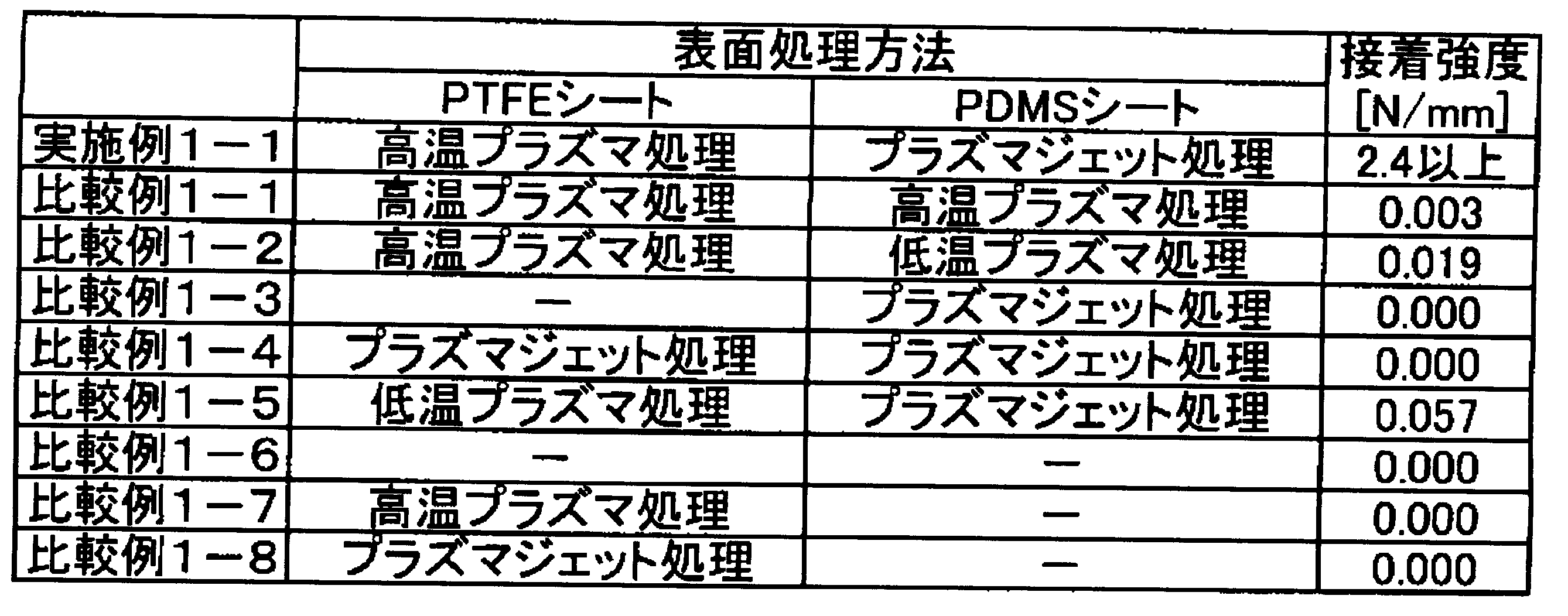
また、実施例1-1の接合体を超音波洗浄機(アズワン株式会社製USK-1R)において、22℃のエタノール中で1分間超音波洗浄しても、PTFEシートとPDMSシートとは剥離しなかった。一方、比較例1-4の接合体を上記超音波洗浄機において、22℃のエタノール中で1分間超音波洗浄すると、PTFEシートとPDMSシートとが剥離した。以上のことから、比較例1-4のように接着強度が低い場合、超音波洗浄を行うだけで容易に剥離してしまうことがわかった。
(実施例2-1、比較例2-1~2)
実施例2-1、比較例2-1、比較例2-2は、PTFEシートをPFAシート(ダイキン工業株式会社製ネオフロン(登録商標)AFシリーズ)に代えた以外は、実施例1-1、比較例1-1、比較例1-2と同様に接合体を作製した。実施例2-1、比較例2-1~2の各接合体について、上記の接着強度の測定を行い、その結果を表2に示した。
実施例2-1、比較例2-1、比較例2-2は、PTFEシートをPFAシート(ダイキン工業株式会社製ネオフロン(登録商標)AFシリーズ)に代えた以外は、実施例1-1、比較例1-1、比較例1-2と同様に接合体を作製した。実施例2-1、比較例2-1~2の各接合体について、上記の接着強度の測定を行い、その結果を表2に示した。

(実施例3-1、比較例3-1~2)
実施例3-1、比較例3-1、比較例3-2は、PTFEシートをETFEシート(ダイキン工業株式会社製ネオフロン(登録商標)EFシリーズ)に代えた以外は、実施例1-1、比較例1-1、比較例1-2と同様に接合体を作製した。実施例3-1、比較例3-1~2の各接合体について、上記の接着強度の測定を行い、その結果を表3に示した。
実施例3-1、比較例3-1、比較例3-2は、PTFEシートをETFEシート(ダイキン工業株式会社製ネオフロン(登録商標)EFシリーズ)に代えた以外は、実施例1-1、比較例1-1、比較例1-2と同様に接合体を作製した。実施例3-1、比較例3-1~2の各接合体について、上記の接着強度の測定を行い、その結果を表3に示した。

(実施例4-1、比較例4-1)
実施例4-1、比較例4-1は、PTFEシートをFEPシート(ダイキン工業株式会社製ネオフロン(登録商標)NFシリーズ)に代えた以外は、実施例1-1、比較例1-1と同様に接合体を作製した。実施例4-1、比較例4-1の各接合体について、上記の接着強度の測定を行い、その結果を表4に示した。
実施例4-1、比較例4-1は、PTFEシートをFEPシート(ダイキン工業株式会社製ネオフロン(登録商標)NFシリーズ)に代えた以外は、実施例1-1、比較例1-1と同様に接合体を作製した。実施例4-1、比較例4-1の各接合体について、上記の接着強度の測定を行い、その結果を表4に示した。

各種樹脂体(PFFEシート、PFAシート、ETFEシート、FEPシート)において、プラズマ照射領域の酸素濃度を0.5体積%未満として上記(II)の高温プラズマ処理を行い、かつ、PDMSシートにおいて、プラズマ照射領域の酸素濃度を1体積%以上として上記(IV)のプラズマジェット処理を行った実施例1-1、実施例2-1、実施例3-1、実施例4-1では接着強度が共に2.4N/mm以上と非常に高かった。一方、各種樹脂体(PFFEシート、PFAシート、ETFEシート、FEPシート)において上記(II)の高温プラズマ処理を行い、かつ、PDMSシートに上記(IV)のプラズマジェット処理を行ったものではない比較例1-1~8、比較例2-1~2、比較例3-1~2、比較例4-1では接着強度が0.1N/mmを大きく下回っており、接合体は容易に剥離する状態であった。
10 高周波電源
11 マッチングユニット
12 チャンバー
13 真空排気系
14 電極
15 電極昇降機構
16 円柱型回転ステージおよび試料ホルダー
17 ハロゲンヒーター
18 内管
19 外管
20 試料(フッ素樹脂を含む樹脂体)
21 放射温度計
31 プラズマ照射ヘッド
32 電極
33 反応室
34 ガス供給装置
35 流入路(ガス導入口)
36 躯体
37 ガス吹き出し口
38 試料(加硫シリコーンゴムを含むゴム体)
39 ステージ
G ガス
11 マッチングユニット
12 チャンバー
13 真空排気系
14 電極
15 電極昇降機構
16 円柱型回転ステージおよび試料ホルダー
17 ハロゲンヒーター
18 内管
19 外管
20 試料(フッ素樹脂を含む樹脂体)
21 放射温度計
31 プラズマ照射ヘッド
32 電極
33 反応室
34 ガス供給装置
35 流入路(ガス導入口)
36 躯体
37 ガス吹き出し口
38 試料(加硫シリコーンゴムを含むゴム体)
39 ステージ
G ガス
Claims (6)
- フッ素系樹脂を含む樹脂体と加硫シリコーンゴムを含むゴム体との接合体。
- 前記加硫シリコーンゴムがジメチルシロキサン単位を含む請求項1に記載の接合体。
- 前記フッ素系樹脂が、ヘキサフルオロプロピレン単位、パーフルオロアルキルビニルエーテル単位、メチレン単位、エチレン単位及びパーフルオロジオキソール単位の少なくとも1種とジフルオロメチレン単位との共重合体、又はポリテトラフルオロエチレンである請求項1又は2に記載の接合体。
- 前記樹脂体の少なくとも一方の表面及び前記ゴム体の少なくとも一方の表面がプラズマ処理されており、前記プラズマ処理された面同士が接合された請求項1~3のいずれか1項に記載の接合体。
- 前記樹脂体と前記ゴム体との接着強度が1.0N/mm以上である請求項1~4のいずれか1項に記載の接合体。
- フッ素系樹脂を含む樹脂体と加硫シリコーンゴムを含むゴム体との接合体の製造方法であって、
前記樹脂体の表面近傍の酸素濃度を0.5体積%未満として、前記樹脂体の表面にプラズマ処理を行い、表面改質された樹脂体を製造する工程と、
前記ゴム体の表面近傍の酸素濃度を1体積%以上として、前記ゴム体の表面にプラズマ処理を行い、表面改質されたゴム体を製造する工程と、
前記表面改質された樹脂体の改質された表面と前記表面改質されたゴム体の改質された表面とを接触させ、加熱及び加圧する工程とを含むことを特徴とする接合体の製造方法。
Priority Applications (2)
| Application Number | Priority Date | Filing Date | Title |
|---|---|---|---|
| US17/059,721 US11383488B2 (en) | 2018-05-31 | 2019-05-30 | Joined body and method for manufacturing same |
| JP2020522579A JP7060276B2 (ja) | 2018-05-31 | 2019-05-30 | 接合体及びその製造方法 |
Applications Claiming Priority (2)
| Application Number | Priority Date | Filing Date | Title |
|---|---|---|---|
| JP2018-105432 | 2018-05-31 | ||
| JP2018105432 | 2018-05-31 |
Publications (1)
| Publication Number | Publication Date |
|---|---|
| WO2019230862A1 true WO2019230862A1 (ja) | 2019-12-05 |
Family
ID=68698957
Family Applications (1)
| Application Number | Title | Priority Date | Filing Date |
|---|---|---|---|
| PCT/JP2019/021452 Ceased WO2019230862A1 (ja) | 2018-05-31 | 2019-05-30 | 接合体及びその製造方法 |
Country Status (3)
| Country | Link |
|---|---|
| US (1) | US11383488B2 (ja) |
| JP (1) | JP7060276B2 (ja) |
| WO (1) | WO2019230862A1 (ja) |
Cited By (1)
| Publication number | Priority date | Publication date | Assignee | Title |
|---|---|---|---|---|
| JP2023081220A (ja) * | 2021-11-30 | 2023-06-09 | 国立大学法人大阪大学 | 樹脂体とゲル体との積層体及びその製造方法 |
Families Citing this family (3)
| Publication number | Priority date | Publication date | Assignee | Title |
|---|---|---|---|---|
| CN117940604A (zh) * | 2021-09-15 | 2024-04-26 | 芝浦机械株式会社 | 表面处理装置以及表面处理方法 |
| CN114199806B (zh) * | 2021-12-10 | 2024-04-09 | 南京大学 | 用afm-ir检测微纳米粗糙的铜箔表面有机物分布的方法 |
| KR102677583B1 (ko) * | 2021-12-30 | 2024-06-21 | (주)에이피아이 | 플라즈마 처리를 이용한 실리콘 고무의 접합방법 |
Citations (8)
| Publication number | Priority date | Publication date | Assignee | Title |
|---|---|---|---|---|
| JPH05147163A (ja) * | 1991-11-28 | 1993-06-15 | Nitto Denko Corp | フツ素樹脂−シリコーンゴム積層体およびその製法 |
| WO2010032728A1 (ja) * | 2008-09-16 | 2010-03-25 | 株式会社朝日ラバー | 三次元化シリコーンゴム接着体 |
| JP2010142573A (ja) * | 2008-12-22 | 2010-07-01 | Coki Engineering Inc | シリンジ用ガスケット及びその製造方法並びに該ガスケットを用いたプレフィルドシリンジ |
| JP2013011280A (ja) * | 2009-02-12 | 2013-01-17 | Board Of Trustees Of The Univ Of Illinois | 磁気的に駆動されるマイクロポンプ |
| WO2013042377A1 (ja) * | 2011-09-22 | 2013-03-28 | 国立大学法人東京工業大学 | 合成樹脂の接着方法 |
| JP2014021081A (ja) * | 2012-07-24 | 2014-02-03 | Hitachi High-Technologies Corp | 分析用マイクロ流路チップの製造方法 |
| JP2016056363A (ja) * | 2014-09-05 | 2016-04-21 | 国立大学法人大阪大学 | 表面改質成型体の製造方法、及び該表面改質成型体を用いた複合体の製造方法 |
| JP2016071344A (ja) * | 2014-09-30 | 2016-05-09 | キヤノン株式会社 | 電子写真用部材、像加熱装置、画像形成装置及び電子写真用部材の製造方法 |
Family Cites Families (5)
| Publication number | Priority date | Publication date | Assignee | Title |
|---|---|---|---|---|
| JP3475085B2 (ja) | 1998-06-29 | 2003-12-08 | 株式会社日立製作所 | 表面改質層を有するフッ素樹脂成形体、フッ素樹脂の表面処理方法、及び処理装置 |
| JP5649772B2 (ja) | 2008-04-25 | 2015-01-07 | 日本バルカー工業株式会社 | フッ素樹脂系成形物の表面改質方法 |
| JP2012233038A (ja) | 2011-04-28 | 2012-11-29 | Osaka Prefecture Univ | 表面改質フッ素樹脂フィルム、その製造方法、その製造装置、表面改質フッ素樹脂フィルムを含む複合体及びその製造方法 |
| WO2015129675A1 (ja) | 2014-02-28 | 2015-09-03 | 国立大学法人大阪大学 | 誘電体基材表面の金属化方法及び金属膜付き誘電体基材 |
| US9588471B2 (en) * | 2014-09-30 | 2017-03-07 | Canon Kabushiki Kaisha | Member for electrophotography, image heating apparatus, image forming apparatus, and method for manufacturing member for electrophotography |
-
2019
- 2019-05-30 WO PCT/JP2019/021452 patent/WO2019230862A1/ja not_active Ceased
- 2019-05-30 JP JP2020522579A patent/JP7060276B2/ja active Active
- 2019-05-30 US US17/059,721 patent/US11383488B2/en active Active
Patent Citations (8)
| Publication number | Priority date | Publication date | Assignee | Title |
|---|---|---|---|---|
| JPH05147163A (ja) * | 1991-11-28 | 1993-06-15 | Nitto Denko Corp | フツ素樹脂−シリコーンゴム積層体およびその製法 |
| WO2010032728A1 (ja) * | 2008-09-16 | 2010-03-25 | 株式会社朝日ラバー | 三次元化シリコーンゴム接着体 |
| JP2010142573A (ja) * | 2008-12-22 | 2010-07-01 | Coki Engineering Inc | シリンジ用ガスケット及びその製造方法並びに該ガスケットを用いたプレフィルドシリンジ |
| JP2013011280A (ja) * | 2009-02-12 | 2013-01-17 | Board Of Trustees Of The Univ Of Illinois | 磁気的に駆動されるマイクロポンプ |
| WO2013042377A1 (ja) * | 2011-09-22 | 2013-03-28 | 国立大学法人東京工業大学 | 合成樹脂の接着方法 |
| JP2014021081A (ja) * | 2012-07-24 | 2014-02-03 | Hitachi High-Technologies Corp | 分析用マイクロ流路チップの製造方法 |
| JP2016056363A (ja) * | 2014-09-05 | 2016-04-21 | 国立大学法人大阪大学 | 表面改質成型体の製造方法、及び該表面改質成型体を用いた複合体の製造方法 |
| JP2016071344A (ja) * | 2014-09-30 | 2016-05-09 | キヤノン株式会社 | 電子写真用部材、像加熱装置、画像形成装置及び電子写真用部材の製造方法 |
Cited By (2)
| Publication number | Priority date | Publication date | Assignee | Title |
|---|---|---|---|---|
| JP2023081220A (ja) * | 2021-11-30 | 2023-06-09 | 国立大学法人大阪大学 | 樹脂体とゲル体との積層体及びその製造方法 |
| JP7765037B2 (ja) | 2021-11-30 | 2025-11-06 | 国立大学法人大阪大学 | 樹脂体とゲル体との積層体及びその製造方法 |
Also Published As
| Publication number | Publication date |
|---|---|
| US11383488B2 (en) | 2022-07-12 |
| US20210213705A1 (en) | 2021-07-15 |
| JPWO2019230862A1 (ja) | 2021-07-29 |
| JP7060276B2 (ja) | 2022-04-26 |
Similar Documents
| Publication | Publication Date | Title |
|---|---|---|
| JP7060276B2 (ja) | 接合体及びその製造方法 | |
| CN106687510B (zh) | 表面改性成形体的制造方法、以及使用了该表面改性成形体的复合体的制造方法 | |
| JP5849308B2 (ja) | 表面改質フッ素樹脂フィルムの製造方法及び表面改質フッ素樹脂フィルム | |
| JP4908617B2 (ja) | 表面改質フッ素樹脂フィルムの製造方法、ゴム複合体の製造方法およびゴム製品 | |
| JP5649772B2 (ja) | フッ素樹脂系成形物の表面改質方法 | |
| JP5895468B2 (ja) | 積層フィルム及びそれを用いたゴム成形体 | |
| EP3178869B1 (en) | Fluororesin tube | |
| WO2009082034A1 (ja) | ゴム成形品 | |
| JP2012514547A (ja) | 多層ポリマー物品およびその製造方法 | |
| JP6846781B2 (ja) | 積層体及びその製造方法 | |
| CN108699398A (zh) | 使用电晕处理使硅酮胶粘剂物质锚固在含氟聚合物膜上 | |
| US11795317B2 (en) | Laminated body including resin body and gel body and method for producing same | |
| US20250121586A1 (en) | Laminated body having resin layer and metal layer and production method for same | |
| JPH03164246A (ja) | 複合構造体 | |
| WO2006059697A1 (ja) | エチレン-テトラフルオロエチレン系共重合体成形物およびその製造方法 | |
| JP2002059486A (ja) | フッ素樹脂フィルムと未加硫ゴムとの加硫接着方法 | |
| WO2010131372A1 (ja) | フッ素樹脂系成形物の表面改質方法 | |
| CN1505115A (zh) | 有机材料膜的处理方法 | |
| JP3593985B2 (ja) | 積層体およびその製法 | |
| KR101741155B1 (ko) | 미세유체 디바이스 제조를 위한 무용매 열가소성-pdms 기판의 본딩 방법 | |
| WO2019244997A1 (ja) | フッ素樹脂フィルム | |
| JP2009013310A (ja) | フッ素樹脂系成形物の表面改質方法 | |
| TW200918561A (en) | Atmospheric plasma double graft polymerization apparatus for polymeric material and method thereof |
Legal Events
| Date | Code | Title | Description |
|---|---|---|---|
| 121 | Ep: the epo has been informed by wipo that ep was designated in this application |
Ref document number: 19811493 Country of ref document: EP Kind code of ref document: A1 |
|
| DPE2 | Request for preliminary examination filed before expiration of 19th month from priority date (pct application filed from 20040101) | ||
| ENP | Entry into the national phase |
Ref document number: 2020522579 Country of ref document: JP Kind code of ref document: A |
|
| NENP | Non-entry into the national phase |
Ref country code: DE |
|
| 122 | Ep: pct application non-entry in european phase |
Ref document number: 19811493 Country of ref document: EP Kind code of ref document: A1 |