WO2019230069A1 - 電池管理装置、電池情報処理システム、及び電池情報処理方法 - Google Patents
電池管理装置、電池情報処理システム、及び電池情報処理方法 Download PDFInfo
- Publication number
- WO2019230069A1 WO2019230069A1 PCT/JP2019/005906 JP2019005906W WO2019230069A1 WO 2019230069 A1 WO2019230069 A1 WO 2019230069A1 JP 2019005906 W JP2019005906 W JP 2019005906W WO 2019230069 A1 WO2019230069 A1 WO 2019230069A1
- Authority
- WO
- WIPO (PCT)
- Prior art keywords
- battery
- unit
- information
- recording
- vehicle
- Prior art date
Links
Images


Classifications
-
- H—ELECTRICITY
- H01—ELECTRIC ELEMENTS
- H01M—PROCESSES OR MEANS, e.g. BATTERIES, FOR THE DIRECT CONVERSION OF CHEMICAL ENERGY INTO ELECTRICAL ENERGY
- H01M10/00—Secondary cells; Manufacture thereof
- H01M10/42—Methods or arrangements for servicing or maintenance of secondary cells or secondary half-cells
- H01M10/425—Structural combination with electronic components, e.g. electronic circuits integrated to the outside of the casing
-
- H—ELECTRICITY
- H01—ELECTRIC ELEMENTS
- H01M—PROCESSES OR MEANS, e.g. BATTERIES, FOR THE DIRECT CONVERSION OF CHEMICAL ENERGY INTO ELECTRICAL ENERGY
- H01M10/00—Secondary cells; Manufacture thereof
- H01M10/42—Methods or arrangements for servicing or maintenance of secondary cells or secondary half-cells
- H01M10/48—Accumulators combined with arrangements for measuring, testing or indicating the condition of cells, e.g. the level or density of the electrolyte
- H01M10/482—Accumulators combined with arrangements for measuring, testing or indicating the condition of cells, e.g. the level or density of the electrolyte for several batteries or cells simultaneously or sequentially
-
- H—ELECTRICITY
- H02—GENERATION; CONVERSION OR DISTRIBUTION OF ELECTRIC POWER
- H02J—CIRCUIT ARRANGEMENTS OR SYSTEMS FOR SUPPLYING OR DISTRIBUTING ELECTRIC POWER; SYSTEMS FOR STORING ELECTRIC ENERGY
- H02J7/00—Circuit arrangements for charging or depolarising batteries or for supplying loads from batteries
- H02J7/0013—Circuit arrangements for charging or depolarising batteries or for supplying loads from batteries acting upon several batteries simultaneously or sequentially
-
- H—ELECTRICITY
- H02—GENERATION; CONVERSION OR DISTRIBUTION OF ELECTRIC POWER
- H02J—CIRCUIT ARRANGEMENTS OR SYSTEMS FOR SUPPLYING OR DISTRIBUTING ELECTRIC POWER; SYSTEMS FOR STORING ELECTRIC ENERGY
- H02J7/00—Circuit arrangements for charging or depolarising batteries or for supplying loads from batteries
- H02J7/0047—Circuit arrangements for charging or depolarising batteries or for supplying loads from batteries with monitoring or indicating devices or circuits
-
- B—PERFORMING OPERATIONS; TRANSPORTING
- B60—VEHICLES IN GENERAL
- B60L—PROPULSION OF ELECTRICALLY-PROPELLED VEHICLES; SUPPLYING ELECTRIC POWER FOR AUXILIARY EQUIPMENT OF ELECTRICALLY-PROPELLED VEHICLES; ELECTRODYNAMIC BRAKE SYSTEMS FOR VEHICLES IN GENERAL; MAGNETIC SUSPENSION OR LEVITATION FOR VEHICLES; MONITORING OPERATING VARIABLES OF ELECTRICALLY-PROPELLED VEHICLES; ELECTRIC SAFETY DEVICES FOR ELECTRICALLY-PROPELLED VEHICLES
- B60L58/00—Methods or circuit arrangements for monitoring or controlling batteries or fuel cells, specially adapted for electric vehicles
- B60L58/10—Methods or circuit arrangements for monitoring or controlling batteries or fuel cells, specially adapted for electric vehicles for monitoring or controlling batteries
- B60L58/12—Methods or circuit arrangements for monitoring or controlling batteries or fuel cells, specially adapted for electric vehicles for monitoring or controlling batteries responding to state of charge [SoC]
-
- B—PERFORMING OPERATIONS; TRANSPORTING
- B60—VEHICLES IN GENERAL
- B60L—PROPULSION OF ELECTRICALLY-PROPELLED VEHICLES; SUPPLYING ELECTRIC POWER FOR AUXILIARY EQUIPMENT OF ELECTRICALLY-PROPELLED VEHICLES; ELECTRODYNAMIC BRAKE SYSTEMS FOR VEHICLES IN GENERAL; MAGNETIC SUSPENSION OR LEVITATION FOR VEHICLES; MONITORING OPERATING VARIABLES OF ELECTRICALLY-PROPELLED VEHICLES; ELECTRIC SAFETY DEVICES FOR ELECTRICALLY-PROPELLED VEHICLES
- B60L58/00—Methods or circuit arrangements for monitoring or controlling batteries or fuel cells, specially adapted for electric vehicles
- B60L58/10—Methods or circuit arrangements for monitoring or controlling batteries or fuel cells, specially adapted for electric vehicles for monitoring or controlling batteries
- B60L58/16—Methods or circuit arrangements for monitoring or controlling batteries or fuel cells, specially adapted for electric vehicles for monitoring or controlling batteries responding to battery ageing, e.g. to the number of charging cycles or the state of health [SoH]
-
- B—PERFORMING OPERATIONS; TRANSPORTING
- B60—VEHICLES IN GENERAL
- B60L—PROPULSION OF ELECTRICALLY-PROPELLED VEHICLES; SUPPLYING ELECTRIC POWER FOR AUXILIARY EQUIPMENT OF ELECTRICALLY-PROPELLED VEHICLES; ELECTRODYNAMIC BRAKE SYSTEMS FOR VEHICLES IN GENERAL; MAGNETIC SUSPENSION OR LEVITATION FOR VEHICLES; MONITORING OPERATING VARIABLES OF ELECTRICALLY-PROPELLED VEHICLES; ELECTRIC SAFETY DEVICES FOR ELECTRICALLY-PROPELLED VEHICLES
- B60L58/00—Methods or circuit arrangements for monitoring or controlling batteries or fuel cells, specially adapted for electric vehicles
- B60L58/10—Methods or circuit arrangements for monitoring or controlling batteries or fuel cells, specially adapted for electric vehicles for monitoring or controlling batteries
- B60L58/18—Methods or circuit arrangements for monitoring or controlling batteries or fuel cells, specially adapted for electric vehicles for monitoring or controlling batteries of two or more battery modules
-
- H—ELECTRICITY
- H01—ELECTRIC ELEMENTS
- H01M—PROCESSES OR MEANS, e.g. BATTERIES, FOR THE DIRECT CONVERSION OF CHEMICAL ENERGY INTO ELECTRICAL ENERGY
- H01M10/00—Secondary cells; Manufacture thereof
- H01M10/42—Methods or arrangements for servicing or maintenance of secondary cells or secondary half-cells
- H01M10/425—Structural combination with electronic components, e.g. electronic circuits integrated to the outside of the casing
- H01M2010/4271—Battery management systems including electronic circuits, e.g. control of current or voltage to keep battery in healthy state, cell balancing
-
- H—ELECTRICITY
- H02—GENERATION; CONVERSION OR DISTRIBUTION OF ELECTRIC POWER
- H02J—CIRCUIT ARRANGEMENTS OR SYSTEMS FOR SUPPLYING OR DISTRIBUTING ELECTRIC POWER; SYSTEMS FOR STORING ELECTRIC ENERGY
- H02J7/00—Circuit arrangements for charging or depolarising batteries or for supplying loads from batteries
- H02J7/0047—Circuit arrangements for charging or depolarising batteries or for supplying loads from batteries with monitoring or indicating devices or circuits
- H02J7/0048—Detection of remaining charge capacity or state of charge [SOC]
-
- H—ELECTRICITY
- H02—GENERATION; CONVERSION OR DISTRIBUTION OF ELECTRIC POWER
- H02J—CIRCUIT ARRANGEMENTS OR SYSTEMS FOR SUPPLYING OR DISTRIBUTING ELECTRIC POWER; SYSTEMS FOR STORING ELECTRIC ENERGY
- H02J7/00—Circuit arrangements for charging or depolarising batteries or for supplying loads from batteries
- H02J7/0047—Circuit arrangements for charging or depolarising batteries or for supplying loads from batteries with monitoring or indicating devices or circuits
- H02J7/005—Detection of state of health [SOH]
-
- Y—GENERAL TAGGING OF NEW TECHNOLOGICAL DEVELOPMENTS; GENERAL TAGGING OF CROSS-SECTIONAL TECHNOLOGIES SPANNING OVER SEVERAL SECTIONS OF THE IPC; TECHNICAL SUBJECTS COVERED BY FORMER USPC CROSS-REFERENCE ART COLLECTIONS [XRACs] AND DIGESTS
- Y02—TECHNOLOGIES OR APPLICATIONS FOR MITIGATION OR ADAPTATION AGAINST CLIMATE CHANGE
- Y02E—REDUCTION OF GREENHOUSE GAS [GHG] EMISSIONS, RELATED TO ENERGY GENERATION, TRANSMISSION OR DISTRIBUTION
- Y02E60/00—Enabling technologies; Technologies with a potential or indirect contribution to GHG emissions mitigation
- Y02E60/10—Energy storage using batteries
-
- Y—GENERAL TAGGING OF NEW TECHNOLOGICAL DEVELOPMENTS; GENERAL TAGGING OF CROSS-SECTIONAL TECHNOLOGIES SPANNING OVER SEVERAL SECTIONS OF THE IPC; TECHNICAL SUBJECTS COVERED BY FORMER USPC CROSS-REFERENCE ART COLLECTIONS [XRACs] AND DIGESTS
- Y02—TECHNOLOGIES OR APPLICATIONS FOR MITIGATION OR ADAPTATION AGAINST CLIMATE CHANGE
- Y02T—CLIMATE CHANGE MITIGATION TECHNOLOGIES RELATED TO TRANSPORTATION
- Y02T10/00—Road transport of goods or passengers
- Y02T10/60—Other road transportation technologies with climate change mitigation effect
- Y02T10/70—Energy storage systems for electromobility, e.g. batteries
Definitions
- the present invention relates to a battery management device, a battery information processing system, and a battery information processing method.
- This application claims priority based on Japanese Patent Application No. 2018-106343 filed on June 1, 2018, and incorporates all the description content described in the above Japanese application.
- HEV and EV are equipped with secondary batteries.
- a secondary battery mounted on a vehicle is configured as an assembled battery by further combining a plurality of battery modules obtained by combining a plurality of battery cells.
- Each of the battery cell and the battery module has battery characteristics individually.
- a battery cell and a battery module having similar or equivalent battery characteristics are combined to be manufactured as one assembled battery. However, after repeated charge and discharge by use, the battery characteristics vary.
- a method has been proposed in which a reusable battery module is selected from an assembled battery whose period has elapsed from the start of use, and the assembled battery is reconfigured.
- Patent Document 1 discloses a method of measuring all battery characteristics such as a full charge capacity and a degree of deterioration for each battery module or battery cell included in an assembled battery and determining whether or not the battery can be reused.
- Non-Patent Document 1 discloses collecting assembled batteries, measuring and classifying the performance (full charge capacity, deterioration degree) of all battery modules of the collected assembled batteries, and reusing them.
- the collected battery modules are classified into those that are reused for driving HEVs and EVs, those that are reused for industrial vehicles such as forklifts, and those that are reused for backup power sources.
- the derivation method of the battery characteristics of the secondary battery is a method of calculating parameters of elements of an equivalent circuit, or a method as disclosed in Patent Document 2 to Patent Document 5. Has been proposed.
- the battery management device includes a calculation unit that calculates a battery characteristic of a secondary battery including a plurality of unit batteries for each unit battery, and a battery characteristic for each unit battery calculated by the calculation unit.
- FIG. 2 is a block diagram showing a configuration of a device mounted on a vehicle V.
- FIG. 3 is a perspective view illustrating a configuration example of a battery module device in Embodiment 1.
- FIG. It is a block diagram which shows the structural example of a battery management apparatus. 3 is a functional block diagram of a module control unit in the first embodiment.
- FIG. It is explanatory drawing which shows the equivalent circuit model of a unit battery (battery module or battery cell). It is explanatory drawing which shows the equivalent circuit model of a unit battery (battery module or battery cell). It is explanatory drawing which shows the equivalent circuit model of a unit battery (battery module or battery cell). It is explanatory drawing which shows the equivalent circuit model of a unit battery (battery module or battery cell).
- FIG. 6 is a block diagram illustrating a part of the configuration of an in-vehicle communication system according to Embodiment 2.
- FIG. 6 is a functional block diagram of a control unit of the battery monitoring apparatus in Embodiment 2.
- FIG. It is a flowchart which shows an example of the process sequence in a vehicle-mounted communication system.
- 5 is a diagram illustrating an outline of a secondary battery reuse system in Embodiment 3.
- FIG. FIG. 10 is a block diagram showing a part of the configuration of an in-vehicle communication system in a third embodiment. It is a block diagram of a server apparatus.
- FIG. 10 is a flowchart illustrating an example of a processing procedure of each device in the secondary battery reuse system according to the third embodiment. It is a figure which shows the outline
- FIG. 10 is a block diagram showing a part of the configuration of an in-vehicle communication system in a fourth embodiment. It is a figure which shows the outline
- This application aims at providing the battery management apparatus, battery information processing system, and battery information processing method which can contribute to the efficient use of resources, such as a rare earth contained in a secondary battery.
- the battery management device includes a calculation unit that calculates, for each unit battery, battery characteristics in a secondary battery including a plurality of unit batteries, and battery characteristics for each unit battery calculated by the calculation unit. Are recorded in association with unit battery identification information for identifying the unit battery and time information indicating the calculated time.
- the battery characteristics calculated based on voltage, current, or temperature in the unit battery (battery cell or battery module unit in which a plurality of battery cells are connected) included in the secondary battery are included in the device. It is recorded in association with information for identifying the unit battery and time information indicating the calculated time. Since the recorded battery characteristics can be read later, detailed battery characteristics can be obtained without requiring measurement during reuse or reproduction.
- each unit battery For each unit battery, record the battery characteristic history in association with the unit battery identification information, so that the history of many unit batteries can be collected and which unit batteries should be combined and reused quickly. Can be identified. The traceability of the unit battery can be improved and the reuse of each unit battery can be promoted. By reusing unit batteries as assembled batteries that have the same characteristics using the battery characteristics when they are actually used, it is possible to prevent rapid deterioration of each unit battery, that is, to efficiently use resources. Can be used.
- the said control part detects the arrival of the replacement
- the battery information processing system is a battery information processing system that processes information indicating characteristics of a secondary battery including a plurality of unit batteries, and is connected to the plurality of unit batteries.
- a plurality of battery management devices that calculate battery characteristics for each unit battery, and the battery characteristics calculated for each unit battery correspond to unit battery identification information that identifies the unit battery and time information that indicates the calculated time.
- a recording device for recording each unit battery.
- the recording device is not provided in the battery management device, but is provided in another device in a device (vehicle) that operates by receiving power supplied from the secondary battery. It may be provided by another external device.
- a device vehicle
- the recording device is easy to comprehensively specify the battery characteristics of a plurality of unit batteries or to make a determination in view of the state of the device (vehicle).
- the recording device is provided in a device different from a device that operates by receiving power from the secondary battery, and the battery management device displays the calculated battery characteristics in the unit battery identification information.
- a transmission unit for transmitting to the recording device in association with the time information and the recording device includes a reception unit for receiving the battery characteristics, and the received battery characteristics of each unit battery are the unit battery identification information and Records in association with time information.
- a recording device is provided outside the device, and the battery management device transmits the calculated battery characteristics in association with the time information to the recording device.
- a large number of battery characteristics of the secondary battery are recorded on the recording device.
- the battery characteristics include at least one of a unit battery full charge capacity, a charge rate, a deterioration degree, and a battery equivalent circuit parameter.
- the reading device that reads the recorded battery characteristic history for each unit battery. Before deterioration progresses, it is incorporated into a new secondary battery or reused for other purposes, thereby realizing efficient use of each secondary battery for each unit battery.
- the detection of the replacement time is performed not by the battery management device but by the reading device, so that comprehensive detection using other information such as information on the device itself provided with the secondary battery is also possible.
- the recording apparatus includes a plurality of processing nodes and a recording medium that perform operations for verifying and approving recording information for recording attribution of information based on an electronic signature obtained from private key information corresponding to a movement source.
- a distributed database network system configured to record the information by dispersing the calculation results in a plurality of recording media, connected to the battery management device, and calculating the battery characteristics calculated by the battery management device.
- the battery characteristics are recorded by a distributed database network system called a so-called block chain.
- a distributed database network system called a so-called block chain.
- the node is different for each unit battery, and creates the transaction by a signature using address information obtained based on secret key information.
- the battery characteristics are recorded using a signature using address information based on secret key information that is different for each unit battery, and from a node connected to the battery management device, in the distributed database network system. Realized by a transaction toward a specific node. Since the address information is given to each unit battery, it corresponds as unit battery identification information.
- the distributed database network system includes, for each unit battery, a node that processes a transaction for registering transfer using unit battery identification information.
- the battery characteristics calculated for each unit battery are associated with time information indicating the calculated time, recorded for each unit battery, and based on the recorded history of battery characteristics for each unit battery, The process which specifies a state for every unit battery is included.
- this application can not only be realized as a battery management apparatus provided with such a characteristic component.
- the battery information management method including the characteristic steps executed by the battery management device, and a program for causing a computer to execute these steps can also be realized.
- a battery module device including a unit battery instead of a single battery management device as a vehicle communication system including a communication device that transmits and receives information by communication with the battery module device, and further as a vehicle including the vehicle communication system It can also be realized. Realized as a semiconductor integrated circuit that realizes part or all of the components of the battery management device, a battery reuse system that uses information processed by the battery management device, and other systems that further include them can do.
- FIG. 1 is a diagram showing an outline of a secondary battery reuse system 100.
- the secondary battery reuse system 100 is a system that supports the reuse of the secondary battery 10 used in the vehicle V that is an EV or HEV.
- the secondary battery reuse system 100 makes it possible to sort out the battery modules 11 having the same battery characteristics from the used secondary batteries 10 and regenerate the secondary battery 10 by combining the sorted battery modules 11. .
- the battery module in which the output voltage at the time of discharging is still high and the deterioration has not progressed is reused for the secondary battery 10 for the vehicle V.
- the battery module 11 can be used in vehicles other than the vehicle V, for example, small vehicles such as forklifts and golf carts, and storage batteries used in backup power sources.
- Secondary battery 10 includes, for example, a lithium ion battery.
- the secondary battery 10 includes a plurality of battery modules (unit batteries) 11 in which a plurality of battery cells (unit batteries) 11a are connected in series or in series and parallel and accommodated in a casing.
- the secondary battery reuse system 100 of Embodiment 1 includes a plurality of battery management devices (see FIG. 2) that calculate battery characteristics for each of a plurality of unit batteries, and a recording device (see FIG. 4) that records the calculated battery characteristics.
- a battery information processing system including a module control unit 12a and a memory 12e).
- the battery characteristics of the battery module 11 of the secondary battery 10 mounted on the vehicle V by the battery information processing system are sequentially calculated and recorded.
- As a method for calculating battery characteristics it is desirable to use a highly accurate method that does not depend on uniform environment, such as a constant temperature. After the decision to reuse, the situation of having to measure for the first time at the time of disassembly is avoided, and if sufficient information is recorded, the measurement at the time of disassembly may be unnecessary.
- the battery characteristic calculation method will be described later.
- the battery characteristics calculated for each unit battery are recorded in association with information for identifying the unit battery so that it can be referred to later. This makes it unnecessary to determine whether or not the secondary battery 10 can be reused and to measure which unit battery should be combined. By referring to the record, it is possible to determine whether the secondary battery 10 is to be provided for a reuse product and which unit battery should be combined.
- FIG. 2 is a block diagram showing the configuration of the device mounted on the vehicle V. As shown in FIG. At least the battery module device 1 and the battery monitoring device 4 are mounted on the vehicle V with respect to the secondary battery 10.
- the power supply system using the secondary battery 10 in the vehicle V includes a relay, a generator (ALT), a starter motor, a battery, an electric load, a start switch, a charger and the like in addition to the battery module device 1. A detailed description of the power supply system is omitted.
- the battery module device 1 uses one battery management device (BMU) 12 in association with one battery module 11 constituting a part of the secondary battery 10.
- the battery management device 12 has an input / output unit 12d (see FIG. 4) and can exchange information with the battery monitoring device 4.
- the battery monitoring device 4 includes a control unit 40, a current detection unit 41, an input / output unit 43, a memory 44, a communication unit 45, and a power supply unit 46.
- the control unit 40 includes a processor such as a CPU (Central Processing Unit), a ROM (Read Only Memory), a RAM (Random Access Memory), a clock unit, a microcomputer having an input / output interface, a dedicated LSI (Large-Scale Integration), Alternatively, it is configured by FPGA (Field-Programmable Gate Array) or the like.
- the control unit 40 passes information through the input / output unit 43 for processing with the battery management device 12 that calculates information indicating the battery characteristics of the unit battery (battery module 11 or battery cell 11a).
- the current detection unit 41 is composed of, for example, a shunt resistor or a hall sensor for detecting the current of the secondary battery 10, and detects the charging current and the discharging current of the secondary battery 10 at a predetermined sampling period.
- the sampling period is, for example, 10 milliseconds, but is not limited thereto.
- the control unit 40 sequentially outputs the current value detected by the current detection unit 41 from the input / output unit 43 to each battery management device 12.
- the secondary battery 10 is configured by further connecting battery modules 11 in which battery cells 11 a are connected in series. Therefore, the current flowing through each unit battery (battery module 11 or battery cell 11a) can be detected by detecting the current at one end of the secondary battery 10 with one current detection unit 41.
- the current detection unit 41 may include a current detection circuit in each of the battery management devices 12 to be described later to detect the current.
- the input / output unit 43 is an input / output interface between the control unit 40 and the plurality of battery management devices 12, and is connected to a communication bus corresponding to the battery management device 12.
- the input / output unit 43 may be replaced with a wireless communication module, and may transmit / receive information to / from each battery management device 12 wirelessly.
- the memory 44 includes a nonvolatile memory such as a flash memory.
- the memory 44 stores management device identification information (BMU-ID) of each of the plurality of battery management devices 12 connected to the own device.
- the management device identification information may be stored in advance by setting, or the control unit 40 may collect management device identification information by inputting / outputting signals to / from each battery management device 12.
- the memory 44 may store unit battery identification information (MID: module ID / CID: cell ID) for identifying a unit battery (battery module 11 or battery cell 11a) of the secondary battery 10 for each unit battery.
- the communication unit 45 is a communication module that realizes communication corresponding to the in-vehicle LAN (Local Area Network).
- the communication unit 45 can transmit and receive information to and from other in-vehicle devices using, for example, CAN (Controller Area Network).
- the communication unit 45 may be a wireless communication module having a wireless communication antenna.
- the power supply unit 46 is a circuit that converts electric power from the secondary battery 10 into a predetermined voltage value and supplies it to each component unit.
- control unit 40 comprehensively specifies the state of the secondary battery 10 from the information obtained from the battery management device 12 of each battery module device 1, and detects an abnormality. Send / receive information to / from other devices.
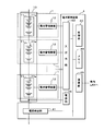
- FIG. 3 is a perspective view illustrating a configuration example of the battery module device 1 according to the first embodiment.
- the battery module device 1 has a quadrangular prism shape as a whole.
- the battery module 11 is configured by stacking a plurality of battery cells 11a each having a plate shape in the thickness direction.
- Each battery cell 11a has a pair of electrode terminals 11b at both ends, and the plurality of electrode terminals 11b at each end are linearly arranged in the stacking direction.
- the battery module 11 is held by the holding member 1a.
- a substantially rectangular parallelepiped portion is formed extending to one end side in the stacking direction of the battery cells 11a, and a support plate 12g for supporting the battery management device 12 is provided on one surface side of the rectangular parallelepiped portion. .
- the battery management device 12 includes a circuit board 12h on which a circuit group (see FIG. 5) that performs processing is mounted.
- the circuit board 12h is substantially the same as the side surface on which the electrode terminals 11b of the battery cells 11a are arranged. Parallel to the support plate 12g.
- a connection terminal 12i is provided at an appropriate location on the circuit board 12h, on the battery cell 11a side.
- the electrode terminals 11b of the plurality of battery cells 11a are connected to the connection terminals 12i by conducting wires 12j.
- the conducting wire 12j is wired along the arrangement of the electrode terminals 11b arranged in the stacking direction, and once connected to one electrode terminal 11b of the battery cell 11a, the other end is connected to the connection terminal 12i.
- FIG. 4 is a block diagram illustrating a configuration example of the battery management device 12. As shown in FIG. 2, a plurality of battery management devices 12 are provided corresponding to each of the battery modules 11, but since all have the same configuration, only one battery management device 12 will be described.
- the battery management device 12 includes a module control unit 12a, a voltage detection circuit 12b, a temperature detection circuit 12c, an input / output unit 12d, a memory 12e, and a power supply circuit 12f that control the operation of the entire device mounted on the circuit board 12h.
- the voltage detection circuit 12b detects the voltage across the battery module 11 at a predetermined sampling period, and outputs information indicating the detection voltage to the module control unit 12a.
- the voltage detection circuit 12b may detect the voltage of each of the plurality of battery cells 11a included in the battery module 11.
- the sampling period is, for example, 10 milliseconds, but is not limited thereto.
- the temperature detection circuit 12c notifies the module controller 12a of the surface temperature of any one or a plurality of locations of the plurality of battery cells 11a in the battery module 11.
- the temperature detection circuit 12c uses a temperature sensor 120c configured by, for example, a thermistor, and reads the temperature based on the signal level of the output signal from the temperature sensor 120c.
- One temperature sensor 120c may be provided for each battery module 11, or one temperature sensor 120c may be provided for each battery cell 11a.
- the use of the thermistor is an example.
- a known temperature sensor such as a temperature sensor, a semiconductor temperature sensor, a thermocouple, or the like may be used.
- the temperature detection may be realized using a temperature sensor installed in any one or a plurality of battery modules 11.
- the battery monitoring device 4 reads the temperature from the output signal of the temperature sensor, and notifies each battery management device 12 via the input / output unit 12d.
- the input / output unit 12d is an input / output terminal between the battery monitoring device 4.
- the battery management device 12 transmits and receives signals (information) to and from the battery monitoring device 4 through the input / output unit 12d.
- the memory 12e is a non-volatile memory such as a flash memory.
- the management device identification information (BMU-ID) of its own device is stored in the non-rewritable area (Read Only) of the memory 12e.
- the memory 12e stores information generated by the process of the module control unit 12a.
- the power supply circuit 12 f is a circuit that converts the power supplied from the battery module 11 into a voltage suitable for driving each component of the battery management device 12 and supplies power to each component of the battery management device 12.
- the module control unit 12a is configured by a processor such as a CPU, a ROM, a RAM, a clock unit, a microcomputer having an input / output interface, a dedicated LSI, or an FPGA.
- a voltage detection circuit 12b, a temperature detection circuit 12c, an input / output unit 12d, and a memory 12e are connected to the input / output interface of the module control unit 12a.
- FIG. 5 is a functional block diagram of the module control unit 12a in the first embodiment.
- the module control unit 12a includes a control unit 121 that controls the entire apparatus, a timer 122, a recording unit 123, an input / output processing unit 124, a voltage acquisition unit 125, a current acquisition unit 126, a temperature acquisition unit 127, a current integration unit 128, a charging rate. It functions as a calculation unit 129, a parameter calculation unit 130, a full charge capacity calculation unit 131, and a deterioration degree calculation unit 132.
- the module control unit 12a controls each unit as the control unit 121, and calculates battery characteristics for each unit battery that is the battery module 11 or the battery cell 11a based on the detected voltage, temperature, and current.
- the module control unit 12a calculates, for example, a full charge capacity (FCC: Full Charge Capacity), a charge rate (SOC: State of Charge), a deterioration degree (SOH: State of Health), and an equivalent circuit parameter as battery characteristics.
- FCC Full Charge Capacity
- SOC State of Charge
- SOH State of Health
- the module control unit 12a functions as a timer 122 using a built-in timing unit.
- the timer 122 outputs the time measurement result to the control unit 121.
- the control unit 121 associates the time information based on the output from the timer 122 so as to store the calculated battery characteristics in time series.
- the module control unit 12a functions as the recording unit 123 using the memory 12e.
- the recording unit 123 records various types of information indicating battery characteristics calculated for each unit battery.
- Information for calculating the battery characteristics is stored in the memory 12e.
- information referred to for calculating a charging rate (SOC) for each unit battery is recorded.
- the memory 12e stores in advance a correlation between the open voltage (OCV: Open Circuit Voltage) of the unit battery (battery cell 11a or battery module 11 unit) and the charging rate.
- OCV Open Circuit Voltage
- the memory 12e stores unit battery identification information (MID) of the battery module 11 to be managed.
- the memory 12e may store unit battery identification information (CID) of each of the plurality of battery cells 11a constituting the battery module 11.
- the unit battery identification information (MID / CID) may be stored by the operation of the recording unit 123 via the specific device or the battery monitoring device 4 by the work operator. preferable.
- a storage medium storing unit battery identification information (MID / CID) is attached to each of the battery module 11 or the battery cell 11a, and the unit battery identification information is read from the storage medium and stored by the control unit 121. Also good.
- the memory 12e stores the initial full charge capacity or equivalent circuit parameter of each unit battery as information for calculating the degree of deterioration for each unit battery.
- This full charge capacity or equivalent circuit parameter may be stored in the order in which the unit batteries are connected and can be read out in a distinguishable manner.
- the memory 12e may store the relationship between the rate of increase in internal resistance and the discharge capacity ratio corresponding to the degree of deterioration as information for calculating the degree of deterioration for each unit battery. These new information may be stored by work by the above-described work operator.
- the module control unit 12a controls transmission / reception of information to / from the battery monitoring device 4 via the input / output unit 12d.
- the input / output processing unit 124 can transmit / receive information (FCC, SOC, SOH, or equivalent circuit parameter) indicating battery characteristics for each unit battery to and from the battery monitoring device 4.
- the module control unit 12a functions as a voltage acquisition unit 125, a current acquisition unit 126, and a temperature acquisition unit 127 that respectively acquire a voltage, a temperature, and a current used for calculating battery characteristics.
- the voltage acquisition part 125 acquires the information which shows the both-ends voltage of the battery module 11 output from the voltage detection circuit 12b, or the voltage of each battery cell 11a.
- the voltage acquisition unit 125 may acquire the both-ends voltage of the battery module 11 and the voltage in each of the battery cells 11a separately from each other.
- the current acquisition unit 126 acquires information indicating the current flowing through the battery module 11 or the battery cell 11a obtained from the battery monitoring device 4 through the input / output unit 12d as the current value of the unit battery.
- the temperature acquisition unit 127 acquires information indicating the temperature output from the temperature detection circuit 12c.
- the module control unit 12a integrates the current value acquired by the current acquisition unit 126 as the current integration unit 128.
- the integrated value of current is obtained by integrating the current with time, and corresponds to the amount of change in the charge amount.
- the integrated value of the current is positive in the case of charging and negative in the case of discharging.
- the integrated value in any given period can be positive or negative depending on the value of the charging current and discharging current in the period.
- the timing for starting the calculation of integration is the activation timing of the secondary battery 10, or the battery module device 1 or the battery monitoring device 4 itself.
- the integral value is calculated continuously. Note that the integrated value may be reset at a predetermined timing, for example, when the battery module 11 is recombined in the case of reuse.
- the module control unit 12a calculates the charge rate for each unit battery that is the battery module 11 or the battery cell 11a.
- the charging rate calculation unit 129 obtains an open circuit voltage in the unit battery that is the battery module 11 or the battery cell 11a.
- the charging rate calculation unit 129 estimates and calculates the charging rate by applying the obtained open circuit voltage to the correlation between the open circuit voltage stored in the recording unit 123 and the charging rate.
- the charge rate calculation unit 129 calculates the charge rate using the charge current and discharge current obtained by integration by the current integration unit 128 and the full charge capacity described later, based on the charge rate at a specific time. May be.
- the module control unit 12a calculates parameters of each element of the equivalent circuit for the unit battery.
- the parameters are the resistance values Ra and Rb in the equivalent circuit, the capacitance Cb of the capacitor, and the like.
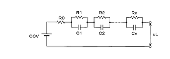
- 6A, 6B, and 6C are explanatory diagrams illustrating an equivalent circuit model of a unit battery (battery module 11 or battery cell 11a).
- the equivalent circuit is represented by a circuit in which a resistor Ra and a parallel circuit of a resistor Rb and a capacitor Cb are connected in series to a voltage source having an open circuit voltage as an electromotive force.
- the resistance Ra corresponds to the electrolyte resistance.
- the resistor Rb corresponds to the charge transfer resistance.
- the capacitor Cb corresponds to the electric double layer capacitance.
- the resistor Ra may include a charge transfer resistor, and the resistor Rb may correspond to a diffused resistor.
- the equivalent circuit of the unit battery is not limited to that shown in FIG. 6A.
- the internal parameters of the equivalent circuit model shown in FIGS. 6A, 6B, and 6C are obtained by estimating the parameters in the approximate expression using the voltage value and the current value, for example, by the least square method.
- a known method may be used for this parameter estimation method (see, for example, “Battery Management Engineering” Shuichi Adachi et al., Tokyo Denki University Publishing, Chapter 6.2.2).
- the internal parameters Ra, Rb, and Cb may be calculated using a Kalman filter.
- the parameter calculation unit 130 is an observation vector when an input signal expressed by a terminal voltage and a current is given to the unit battery, and a state when the same input signal is given to the equivalent circuit model of the unit battery. Compare with vector. As a result of the comparison, the parameter calculation unit 130 repeatedly corrects the equivalent circuit model so that the error between both vectors is minimized by multiplying the error between the two by the Kalman gain and feeding back to the equivalent circuit model. In this way, the parameter calculation unit 130 can also estimate the internal parameters.
- the module control unit 12a calculates the full charge capacity for each battery cell 11a.
- Various methods can be adopted as a method for calculating the full charge capacity by the full charge capacity calculation unit 131.
- the full charge capacity calculation unit 131 performs the first charging of the battery cell 11a at the first time point when the start switch is in the OFF state within the first trip period from the ON time point of the start switch of the vehicle V to the next ON time point.
- the first charging rate is calculated by the charging rate calculation unit 129 by applying the open circuit voltage to the stored correlation.
- the full charge capacity calculation unit 131 calculates the second charge rate by the charge rate calculation unit 129 based on the second open circuit voltage at the second time point when the start switch is in the OFF state during the second trip period.
- the full charge capacity calculation unit 131 calculates the charge / discharge amount based on the charge / discharge current acquired by the current acquisition unit 126 between the first time point and the second time point by the current integration unit 128.
- the full charge capacity calculation unit 131 calculates the full charge capacity of each battery cell 11a based on the calculated first charge rate, second charge rate, and charge / discharge amount.
- the full charge capacity calculation unit 131 can also calculate the full charge capacity for each battery module 11 based on the full charge capacity for each battery cell 11a. As a method for calculating the full charge capacity, other known methods or new methods may be used.
- the module control unit 12a calculates the deterioration level for each unit battery that is the battery module 11 or the battery cell 11a.
- the deterioration degree calculation unit 132 calculates the deterioration degree by comparing the full charge capacity of the unit battery calculated by the full charge capacity calculation unit 131 with the initial full charge capacity stored in the recording unit 123. .
- the deterioration degree calculation unit 132 obtains the ratio (increase) of the internal resistance value R calculated by the parameter calculation unit 130 to the initial value R0 for the secondary battery 10 and stores the internal resistance stored in the recording unit 123.
- the degree of deterioration may be calculated based on the correlation between the increase rate and the discharge capacity ratio. Further, the deterioration degree calculation unit 132 may calculate the deterioration degree by comparing the initial value of the equivalent circuit parameter stored in the recording unit 123 with the value calculated by the parameter calculation unit 130.
- Battery characteristics can be calculated by various methods as the above-described charging rate calculation unit 129, parameter calculation unit 130, full charge capacity calculation unit 131, and deterioration degree calculation unit 132.
- the charging rate calculation unit 129, the parameter calculation unit 130, the full charge capacity calculation unit 131, and the deterioration degree calculation unit 132 are disclosed in, for example, Japanese Patent Laid-Open Nos. 2018-013456, 2017-203659, and 2017-194284. The method disclosed in JP-A-2017-194283 and the like may be used.
- the module control unit 12a calculates, as a control unit 121, all or a part of battery characteristics such as a charging rate, an equivalent circuit parameter, a full charge capacity, and a deterioration degree at a predetermined cycle such as 10 milliseconds, and temporarily stores them. Then, charge / discharge control according to the battery characteristics is performed.
- the control unit 121 outputs the battery characteristics to the battery monitoring device 4, and the battery monitoring device 4 calculates the battery characteristics of the entire secondary battery 10 and performs charge / discharge control as a whole, or traveling control to other in-vehicle devices. Provide information to
- the recording unit 123 records these pieces of information indicating the sequentially calculated battery characteristics in association with the time information in the memory 12e at a predetermined recording timing.
- FIG. 7 is a diagram illustrating an example of the content of information recorded by the recording unit 123.
- the recording unit 123 associates information indicating the battery characteristics (FCC, SOC, SOH, or equivalent circuit parameters) with the unit battery identification information (MID / CID) and the management device identification information (BMU-ID), so that the timer 122 It is recorded with time information (calculation time) that can be acquired with.
- the recording timing is, for example, the timing at which the start switch is turned on from the off state at regular intervals such as once a month.
- the recording unit 123 continuously determines whether or not the recording timing has arrived, and performs recording processing when determining that it has arrived.
- the recording timing may be an instruction from the battery monitoring device 4 or a timing when a request is made. In this case, a request may be made via a communication medium from another in-vehicle control device (not shown).
- the recording process is continuously performed by the battery management device 12 in both the vehicle V in which the new secondary battery 10 is mounted and the vehicle V in which the reused secondary battery 10 is mounted.
- the battery characteristics are recorded by the recording unit 123 so as to be identifiable for each unit battery (battery module 11 or battery cell 11a) and in association with time information.
- the battery characteristics recorded by the recording unit 123 can be read later.
- a reading device such as a diagnostic terminal is used, and the reading device is connected to the communication unit 45 of the battery monitoring device 4 via a vehicle gateway device (not shown) so as to be communicable.
- the reading device can read the battery characteristics recorded in the recording unit 123 in association with the unit battery identification information (MID / CID) and the management device identification information (BMU-ID).
- the operator separately uses a terminal corresponding to the input / output unit 12d, and the battery characteristics recorded by the recording unit 123 on this terminal are used as unit battery identification information (MID / (CID) and management device identification information (BMU-ID) may be read in association with each other.
- MID / (CID) unit battery identification information
- BMU-ID management device identification information
- the battery information processing system including the charging rate calculation unit 129 that calculates the battery characteristics, the parameter calculation unit 130, the full charge capacity calculation unit 131, the deterioration degree calculation unit 132, and the recording unit 123.
- the secondary battery reuse system 100 can collect battery characteristics for each unit battery identification information (MID / CID) and management device identification information (BMU-ID) read when the vehicle V is inspected. Accordingly, it is possible to quickly manage which identification information of the battery module 11 or the battery cell 11a should be combined. The state of each battery module 11 or each battery cell 11a can be detected without performing another measurement when the secondary battery 10 is disassembled.
- the module control unit 12a of the battery management device 12 detects whether or not the replacement time has arrived from the state of detection based on the battery characteristics recorded by the recording unit 123. You may make it notify the arrival of replacement
- the battery information processing system included in the secondary battery reuse system 100 includes a plurality of battery management devices 12 that calculate battery characteristics for each of a plurality of unit batteries, and a record that records the calculated battery characteristics.
- Apparatus the control unit 40 and the memory 44 in FIG. 8).
- FIG. 8 is a block diagram showing a part of the configuration of the in-vehicle communication system in the second embodiment.
- the in-vehicle communication system shown in FIG. 8 is a system in the vehicle V included in the secondary battery reuse system 100 shown in the first embodiment.
- the components common to the first embodiment are denoted by the same reference numerals, and detailed description thereof is omitted.
- the vehicle V is mounted with an in-vehicle communication system including a battery monitoring device 4 connected to the secondary battery 10, a GW (Gateway) device 2 connected to the in-vehicle LAN, and an ECU 5. .
- the GW apparatus 2 includes a control unit 20 and an in-vehicle communication unit 21.
- the control unit 20 uses one or more processors and a memory to execute processing for controlling each component.
- the GW apparatus 2 is a communication apparatus that relays information between different communication media included in the in-vehicle LAN.
- the in-vehicle communication unit 21 realizes transmission / reception of information between the battery monitoring device 4 and another ECU 5 by in-vehicle communication.
- the in-vehicle communication unit 21 performs communication by CAN communication, but may perform communication by wired communication or wireless communication using another protocol.
- the ECU 5 is an in-vehicle device that includes a control unit 50, an in-vehicle communication unit 51, a display unit 52, and an audio output unit 53, and exhibits a function of outputting a message for a passenger. Note that only one of the display unit 52 and the audio output unit 53 may be provided.
- the control unit 50 controls the display unit 52 and the audio output unit 53 using a microcomputer.
- the in-vehicle communication unit 51 is connected to the in-vehicle LAN to realize transmission / reception of information with other in-vehicle devices.
- the display unit 52 is an indicator lamp provided in a panel of instruments including a speedometer on the instrument panel.
- the display unit 52 may use an LED (Light Emitting Diode).
- the display unit 52 may be a head-up display.
- the display unit 52 incorporates a touch panel used in a navigation system or the like, and may use a display panel such as an LCD (Liquid Crystal Display) or an organic EL (Electro Luminescence).
- the display unit 52 displays images or characters based on the control of the control unit 50.
- the sound output unit 53 is a speaker and emits sound or sound effect based on the control of the control unit 50.
- FIG. 9 is a functional block diagram of the control unit 40 of the battery monitoring device 4 according to the second embodiment.
- the control unit 40 of the battery monitoring device 4 functions as a battery characteristic acquisition unit 401, a recording unit 402 that records battery characteristics in the memory 44, and a replacement time detection unit 403.
- the module control unit 12a of the battery management device 12 serves as the recording unit 123 that sequentially records the battery characteristics in the memory 12e, which is a nonvolatile storage medium, even if the battery characteristics to be sequentially calculated are temporarily stored. Does not have to work.
- the battery characteristic acquisition unit 401 acquires the battery characteristics transmitted from the battery management device 12 of each battery module device 1 through the input / output unit 43 together with time information. Thereby, the battery monitoring device 4 functions as a battery characteristic reading device.
- the recording unit 402 performs processing for recording the battery characteristics acquired via the input / output unit 43 in the memory 44 at a predetermined timing.
- the replacement time detection unit 403 refers to information recorded in the memory 44 at a predetermined timing, and executes processing related to detection of abnormality in the secondary battery 10 and promotion of provision of the secondary battery 10 for reuse.
- FIG. 10 is a flowchart showing an example of a processing procedure in the in-vehicle communication system.
- the control unit 40 of the battery monitoring device 4 determines whether it is a recording timing (step S401).
- the recording timing is, for example, every fixed period such as once a month.
- the control unit 40 determines that it is the recording timing when a certain period of time has elapsed and the start switch is next turned on from the off state.
- control unit 40 determines that it is not the recording timing (S401: NO), it returns the process to step S401.
- the control unit 40 sequentially instructs the battery management device 12 of each battery module device 1 to read (step S402).
- the control unit 121 sequentially calculates (for example, 10 milliseconds) in accordance with an instruction from the battery monitoring device 4 and reads out the temporarily stored battery characteristics (step S101).
- the control unit 121 associates the read battery characteristics with the unit battery identification information (CID / BID) and management device identification information (BMU-ID) stored in the recording unit 123, and inputs / outputs the data to the battery monitoring device 4. 12d is output (step S102).
- the control unit 121 also outputs time information for calculating the output battery characteristics.
- the control unit 40 receives the battery characteristics transmitted from the battery management device 12 in response to the read instruction, at the communication unit 45 (step S403).
- the control unit 40 acquires travel information (travel distance, average speed, fuel consumption, etc.) of the vehicle V from another device via the in-vehicle LAN by the communication unit 45 (step S404).
- the control unit 40 records the received battery characteristics in the memory 44 in association with the unit battery identification information (CID / BID), the management apparatus identification information (BMU-ID), and the travel information acquired in Step S404 (Step S404). S405). In step S405, the control unit 40 also records the time information received correspondingly.
- control unit 40 Based on the battery characteristics recorded in time series in the memory 44, the control unit 40 refers to the travel information, and whether the replacement time of the secondary battery 10 has already arrived or does it come within one year thereafter It is determined whether or not (step S406).
- the control unit 40 may determine whether or not it is predicted to arrive within one year, and may determine that it has arrived when it is determined that it will arrive. In step S406, in particular, the control unit 40 determines that the replacement time has come when the degree of deterioration is a predetermined rate, for example, 70%, that is, when the full charge capacity is 70% or less compared to the new state. Further, the control unit 40 may determine whether or not the output voltage at the time of full charge is equal to or lower than a predetermined ratio as compared with a new state. When the fuel consumption included in the travel information is in a deteriorated state, the control unit 40 may determine that the replacement time has arrived.
- a predetermined rate for example, 70%
- the control unit 40 may determine whether or not the output voltage at the time of full charge is equal to or lower than a predetermined ratio as compared with a new state.
- step S406 If it is determined in step S406 that the replacement time has not arrived (S406: NO), the control unit 40 ends the process. In this case, the control unit 40 stands by again from step S401 until it is the recording timing.
- step S406 When it is determined in step S406 that the replacement time has arrived or has arrived (S406: YES), the control unit 40 transmits an arrival notification of the replacement time of the secondary battery 10 from the communication unit 45 to the ECU 5. (Step S407). And the control part 40 of the battery monitoring apparatus 4 complete
- the ECU 5 receives the arrival notification by the in-vehicle communication unit 51 (step S501), and the control unit 50 displays a message indicating the replacement time on the display unit 52 (step S502), and sounds a warning sound.
- the output is output from the output unit 53 (step S503).
- the control unit 40 notifies the arrival of the replacement time separately from the abnormality detection of the secondary battery 10, so that the battery module 11 or the battery is deteriorated before it can be used even in reuse.
- the replacement of the cell 11a can be promoted.
- the battery monitoring device 4 connected to all the battery management devices 12 rather than each of the battery management devices 12 collects the battery characteristics and records them so that they can be read later. It is possible to make a comprehensive judgment on the arrival of time, including driving information.
- FIG. 11 is a diagram showing an outline of the secondary battery reuse system 200 in the third embodiment.
- the battery characteristics for each unit battery of the secondary battery 10 of each vehicle V are collected by the server device 3 existing outside the vehicle V and recorded in the database 301.
- the secondary battery reuse system 200 of Embodiment 3 includes a plurality of battery management devices 12 that calculate battery characteristics for each of a plurality of unit batteries, and a recording device (server device 3 and database 301) that records the calculated battery characteristics. Including a battery information processing system.
- the server device 3 and the database 301 are managed by the vehicle V that inspects the secondary battery 10, the inspection organization of the secondary battery 10, an inspection service provider that is a third party, or the like.
- the GW device 2 shown in the second embodiment has a function of communicating with the outside of the vehicle in addition to the in-vehicle communication unit 21, and can transmit / receive information to / from the server device 3 via the network N.
- the network N includes a public communication network and a carrier network that realizes wireless communication according to a predetermined mobile communication standard. It may include a network of optical beacons and ITS (Intelligent Transport Systems).
- the processing in the battery management device 12 and the battery monitoring device 4 in the third embodiment is the same as the processing described in the first and second embodiments, except for the processing for setting the recording location as the database 301.
- the configurations common to the first and second embodiments are denoted by the same reference numerals, and detailed description thereof is omitted.
- FIG. 12 is a block diagram showing a part of the configuration of the in-vehicle communication system according to the third embodiment.
- the GW apparatus 2 includes an out-of-vehicle communication unit 22.
- the vehicle exterior communication unit 22 is a unit that transmits and receives information to and from a communication device (including a wireless communication device brought into the vehicle) other than the vehicle-mounted device.
- the communication unit 22 outside the vehicle is connected to the network N via the communication device, and can send and receive information to and from the server device 3.
- the out-of-vehicle communication unit 22 is a wireless communication unit capable of communication connection to an access point AP of a communication network provided by a communication carrier provided by Wi-Fi communication.
- the external communication unit 22 may use Bluetooth (registered trademark).
- the vehicle exterior communication unit 22 may be a wireless communication module according to a predetermined mobile communication standard.
- the outside communication unit 22 may transmit / receive information to / from the server device 3 via the communication device outside the vehicle and the network N using an optical beacon or an ITS wireless communication standard.
- the communication unit 22 outside the vehicle may be an interface such as a diagnosis port for abnormality diagnosis or log extraction, and the control unit 20 may transmit information from the communication unit 22 outside the vehicle to a predetermined diagnosis terminal. In this case, the information received by the diagnosis terminal is transmitted to the server device 3 via the network N via the terminal device used in the inspection organization.
- FIG. 13 is a block diagram of the server device 3.
- the server device 3 uses a server computer and includes a control unit 30, a recording unit 31, and a communication unit 32.
- the server apparatus 3 is described as a single server computer, but a configuration in which a plurality of server computers perform processing in a distributed manner may be used.
- the control unit 30 is a processor using a CPU or a GPU (Graphics Processing ⁇ Unit), and executes processing by controlling each component using a built-in memory such as a ROM and a RAM.
- the control unit 30 executes information processing based on the computer program recorded in the recording unit 31.
- the recording unit 31 uses a non-volatile storage medium such as a hard disk, SSD (Solid State Drive), flash memory, or the like.
- the recording unit 31 records information indicating battery characteristics in the database 301 in association with unit battery identification information (MID / CID) for identifying each unit battery (battery module 11 or battery cell 11a).
- the database 301 may be configured by a storage device outside the server device 3.
- the communication unit 32 is a communication device that realizes communication connection and data transmission / reception via the network N.
- the communication unit 32 is a network card corresponding to the network N.
- FIG. 14 is a flowchart illustrating an example of a processing procedure of each device in the secondary battery reuse system 200 according to the third embodiment.
- the control unit 40 of the battery monitoring device 4 receives battery characteristics from the battery management device 12 (S403), and acquires travel information of the vehicle V via the in-vehicle LAN (S404).
- the control unit 40 associates the battery characteristics received in step S403 with identification information such as unit battery identification information (CID / BID) and management device identification information (BMU-ID) and the travel information acquired in step S404. It transmits to server apparatus 3 address (step S415).
- step S415 the control unit 40 transmits both the time information received from the battery management device 12 corresponding to the battery characteristics and the vehicle body identification information of the vehicle V.
- the communication unit 32 receives the battery characteristics (step S301).
- the control unit 30 records the battery identification received by the communication unit 32 in the database 301 in association with the unit battery identification information (CID / BID) and the management device identification information (BMU-ID) (step S302).
- the control unit 30 records the time information received correspondingly in the database 301.
- the control unit 30 reads the battery characteristics recorded for each unit battery in the database 301 (step S303). Thereby, the server device 3 functions as a battery characteristic reading device. Based on the read battery characteristics, the control unit 30 determines whether or not the replacement time has arrived for each vehicle V, that is, for each secondary battery 10 (step S304). In step S304, the control unit 30 collects battery characteristics for each unit battery associated with the same vehicle body identification information, and as described in step S405 of the flowchart of FIG. Judgment may be made based on the travel information. When the server device 3 with sufficient hardware resources can determine whether or not the replacement time has come, the control unit 30 performs statistical processing (regression analysis) in advance based on the recording of time-series battery characteristics for each unit. , T method, etc.) or deep learning. In these determination methods, the control unit 30 uses a learning model prepared in advance to output the predicted unit battery life when the input is battery characteristics, and refers to the output life. It is good to judge.
- step S304 If it is determined in step S304 that the replacement time has not arrived (S304: NO), the control unit 30 ends the process.
- step S304 When it is determined in step S304 that the replacement time has arrived or has arrived (S304: YES), the control unit 30 transmits an exchange time arrival notification to the vehicle V (step S305), and ends the process. To do.
- step S304 the control unit 30 sends vehicle body identification information, unit battery identification information (CID / BID), and management device identification information (manufactured by another vehicle V manufacturer, dealer, inspector, or secondary battery 10 manufacturer).
- BMU-ID management device identification information
- the unit battery included in the secondary battery 10 in use can be replaced with a new secondary battery 10 or a regenerated secondary battery 10 while being recognized by a dealer or a manufacturer. It is possible to realize a service such as presenting the merits of this to the user and promote the use of the secondary battery reuse system 200.
- the battery monitoring device 4 or the ECU 5 receives the arrival notification from the server device 3 (step S416), and notifies the user of the arrival of the replacement time using the in-vehicle display unit 52 or the like.
- the server device 3 outside the vehicle V records the battery characteristics in the database 301 for each unit battery. Although it is desirable to simplify the device mounted on the vehicle V as much as possible, it can be expected to make a highly accurate judgment by recording the server device 3 having abundant resources so that it can be read. Further, by making the determination at the server device 3, not only can the user know that the replacement time has arrived, but also notification to the battery manufacturer and the manufacturer of the vehicle V can be easily realized. It is also easy to realize a service that prompts the secondary battery reuse system 200 to provide a unit battery at the time of inspection by the manufacturer of the vehicle V. By providing the unit battery to the secondary battery reuse system 200, it is possible to present a merit such as a price discount for the new secondary battery 10 from the manufacturer of the vehicle V.
- FIG. 15 is a diagram showing an outline of the secondary battery reuse system 300 in the fourth embodiment.
- battery characteristics are recorded by a distributed DB network system 600 called a so-called block chain.
- the distributed DB network system 600 includes a storage medium and includes a plurality of nodes 601 that perform predetermined calculations.
- a secondary battery reuse system 300 according to Embodiment 4 includes a plurality of battery management devices 12 that calculate battery characteristics for each of a plurality of unit batteries, and a recording device (distributed DB network system) that records the calculated battery characteristics. Including a battery information processing system.
- a vehicle V is mounted on a vehicle V, which is a communication device having a secret key itself or a wallet address based on the secret key.
- the in-vehicle node 6 can be connected to the battery monitoring device 4 to acquire the battery characteristics for each unit battery of the secondary battery 10.
- the secret key itself is assigned to each unit battery, and the in-vehicle node 6 stores and uses the wallet address based on the secret key for each unit battery included in the secondary battery 10 of the vehicle V in which it is mounted. Also good.
- a plurality of wallet addresses that can be created based on the secret key corresponding to the in-vehicle node 6 may be assigned to each of the plurality of unit batteries included in the secondary battery 10.
- the wallet address of each unit battery may be used as unit battery identification information.
- FIG. 16 is a block diagram showing a part of the configuration of the in-vehicle communication system according to the fourth embodiment.
- the vehicle-mounted node 6 connected to the battery monitoring device 4 so as to be communicable is mounted on the vehicle V.
- the in-vehicle node 6 includes a processing unit 60, a memory 61, an in-vehicle communication unit 62, and an out-of-vehicle communication unit 63.
- the processing unit 60 uses a processor such as a CPU and a GPU, and a memory.
- the processing unit 60 may be configured as one piece of hardware (SoC: System On a Chip) in which a processor, a memory, and further a memory 61, an in-vehicle communication unit 62, and an out-of-vehicle communication unit 63 are integrated.
- SoC System On a Chip
- the secret key may be stored in the memory of the processing unit 60 in a non-rewritable manner in hardware (wallet chip).
- the memory 61 uses a flash memory and stores information such as programs and data referred to by the processing unit 60.
- the above-described secret key may be stored in the memory 61.
- the memory 61 stores a public key based on the secret key and a wallet address.
- the in-vehicle communication unit 62 realizes information transmission / reception with the battery monitoring device 4.
- the in-vehicle node 6 may not communicate with other in-vehicle devices other than the battery monitoring device 4.
- the in-vehicle communication unit 63 is a unit that transmits and receives information by wireless signals to and from communication devices other than the in-vehicle device (including wireless communication devices brought into the vehicle).
- the communication unit 63 outside the vehicle is communicably connected to the network N via the communication device, and can transmit information to any one of the plurality of nodes 601 included in the distributed DB network system 600.
- the vehicle exterior communication unit 63 is, for example, a wireless communication module according to a predetermined mobile communication standard.
- the out-of-vehicle communication unit 63 is a wireless communication unit capable of communication connection to an access point AP of a communication network provided by a communication provider.
- the external communication unit 63 may use Bluetooth (registered trademark).
- the in-vehicle node 6 configured in this way outputs (transmits) a transaction for recording battery characteristics to the distributed DB network system 600 including the node 601 and the nodes 601 outside the vehicle V.
- a signature based on the wallet address (unit battery identification information) stored in the in-vehicle node 6 is used.
- a transaction for transmitting battery characteristics from the wallet address of the in-vehicle node 6 to the wallet address of a specific node (registration node) can be used.
- the battery characteristics may be transmitted after being converted to a hash value.
- a transaction for recording battery characteristics based on the wallet address of each in-vehicle node 6 in the distributed DB network system 600 undergoes a process of verifying a signature included in the transaction using the public key of the in-vehicle node 6, and any node 601. In addition, it is recorded so that it can be browsed via communication from a device outside the distributed DB network system 600.
- the use of the battery characteristics recorded in the distributed DB network system 600 will be described.
- the battery characteristics recorded in the distributed DB network system 600 can be confirmed as highly accurate battery characteristics for each unit battery as shown in the first to third embodiments. Therefore, it is possible for an operator to grasp the degree of deterioration of each unit battery without an inspection at the stage of disassembling the secondary battery 10.
- the in-vehicle node 6 that can output a transaction to the distributed DB network system 600 that is a so-called block chain, it is possible to distribute information on the unit battery on the distributed DB network system 600.
- FIG. 17 is a diagram showing an outline of information distribution in the distributed DB network system 600.
- the in-vehicle node 6 outputs a transaction for recording the battery characteristics with high accuracy obtained by the battery management device 12 for each unit battery.
- distribution of unit cells as resources can be recorded.
- the distributed DB network system 600 may be provided with a specific node 601 configured to execute a smart contract for processing a transaction for registering a transfer.
- each unit battery included in the secondary battery 10 is mounted on the vehicle V from a specific node managed by the manufacturer of the secondary battery 10 or the manufacturer of the vehicle V itself.
- a transaction for transferring the unit battery identification information (CID / BID) to the in-vehicle node 6 is output.
- the wallet address of the in-vehicle node 6 to which the unit battery identification information (CID / BID) is transferred becomes clear on the distributed DB network system 600.
- the transaction at the time of recombination may transfer unit battery identification information (CID / BID) from the in-vehicle node 6 of the original vehicle V to a specific node 601 managed by the battery supplier performing the recombination.
- the transfer transaction is set so that recording to the distributed DB network system 600 can be realized for the first time by multisig using a secret key or the like corresponding to each of the transfer source node and the transfer destination node (device). Good. Further, at the time of relocation, a transaction for paying the price of virtual currency may be recorded as a consideration for relocation between the in-vehicle nodes 6. As a result, for the provision of the unit battery to the secondary battery reuse system 300, the vehicle V itself can be paid with a digital asset such as a virtual currency.
- the secret key of the vehicle-mounted node 6 of the vehicle V is managed by the user who is the owner of the vehicle V, so that the virtual currency can be paid to the owner who provides the secondary battery 10.
- the transfer transaction is, for example, a node such as the in-vehicle node 6 via a node that can be operated by an owner who knows the secret key of the secondary battery 10 (initially, the manufacturer of the secondary battery 10 or the manufacturer of the vehicle V). It is good to output by accepting a transfer instruction.
- the function of the in-vehicle node 6 shown in the fourth embodiment may be incorporated in the battery monitoring device 4.
- the distributed DB network system 600 to record the battery characteristics, identification information, and the like related to the unit batteries included in the secondary battery 10, it is possible to activate the distribution of the unit cells that are resources, Traceability can be improved and the value of the unit cell can be guaranteed.
- the secondary battery 10 has been described with reference to an example in which the secondary battery 10 is first used to supply driving power for the vehicle V.
- the secondary battery reuse system 100 (200 or 300) records not only the vehicle V but also secondary battery such as carts, battery characteristics in use in stationary power storage devices, etc., so that it can be collected. May be.
- the secondary battery reuse system 100 (200 or 300) of the present disclosure can be applied to any system that uses a secondary battery in which a plurality of unit batteries (battery cells 11a or battery modules 11) are combined.
Landscapes
- Engineering & Computer Science (AREA)
- Manufacturing & Machinery (AREA)
- Chemical & Material Sciences (AREA)
- Chemical Kinetics & Catalysis (AREA)
- Electrochemistry (AREA)
- General Chemical & Material Sciences (AREA)
- Power Engineering (AREA)
- Microelectronics & Electronic Packaging (AREA)
- Secondary Cells (AREA)
- Charge And Discharge Circuits For Batteries Or The Like (AREA)
- Tests Of Electric Status Of Batteries (AREA)
- Electric Propulsion And Braking For Vehicles (AREA)
Priority Applications (4)
| Application Number | Priority Date | Filing Date | Title |
|---|---|---|---|
| CN201980029337.6A CN112055912A (zh) | 2018-06-01 | 2019-02-18 | 电池管理装置、电池信息处理系统以及电池信息处理方法 |
| JP2020521693A JP7156373B2 (ja) | 2018-06-01 | 2019-02-18 | 電池管理装置、電池情報処理システム、及び電池情報処理方法 |
| US17/058,290 US20210367277A1 (en) | 2018-06-01 | 2019-02-18 | Battery management device, battery information processing system, and battery information processing method |
| DE112019002799.9T DE112019002799T5 (de) | 2018-06-01 | 2019-02-18 | Batterieverwaltungsvorrichtung, Batterieinformationsverarbeitungssystem und Batterieinformationsverarbeitungsverfahren |
Applications Claiming Priority (2)
| Application Number | Priority Date | Filing Date | Title |
|---|---|---|---|
| JP2018106343 | 2018-06-01 | ||
| JP2018-106343 | 2018-06-01 |
Publications (1)
| Publication Number | Publication Date |
|---|---|
| WO2019230069A1 true WO2019230069A1 (ja) | 2019-12-05 |
Family
ID=68697980
Family Applications (1)
| Application Number | Title | Priority Date | Filing Date |
|---|---|---|---|
| PCT/JP2019/005906 WO2019230069A1 (ja) | 2018-06-01 | 2019-02-18 | 電池管理装置、電池情報処理システム、及び電池情報処理方法 |
Country Status (5)
| Country | Link |
|---|---|
| US (1) | US20210367277A1 (zh) |
| JP (1) | JP7156373B2 (zh) |
| CN (1) | CN112055912A (zh) |
| DE (1) | DE112019002799T5 (zh) |
| WO (1) | WO2019230069A1 (zh) |
Cited By (7)
| Publication number | Priority date | Publication date | Assignee | Title |
|---|---|---|---|---|
| JP2020166928A (ja) * | 2019-03-28 | 2020-10-08 | 本田技研工業株式会社 | 選定装置、選定方法、及びプログラム |
| JP6944579B1 (ja) * | 2020-10-22 | 2021-10-06 | 株式会社日本総合研究所 | 情報処理方法及び情報処理装置 |
| JP2021191159A (ja) * | 2020-06-02 | 2021-12-13 | トヨタ自動車株式会社 | 管理装置、及び車両販売システム |
| WO2022034704A1 (ja) * | 2020-08-13 | 2022-02-17 | TeraWatt Technology株式会社 | 情報処理装置、情報処理方法、及びプログラム |
| JP2022068834A (ja) * | 2020-10-22 | 2022-05-10 | 株式会社日本総合研究所 | 情報処理方法及び情報処理装置 |
| JP2023513685A (ja) * | 2020-08-27 | 2023-04-03 | エルジー エナジー ソリューション リミテッド | バッテリー統合管理プラットフォームサービスシステム及び方法 |
| JP7403563B2 (ja) | 2022-01-14 | 2023-12-22 | 本田技研工業株式会社 | バッテリ情報管理方法およびプログラム |
Families Citing this family (6)
| Publication number | Priority date | Publication date | Assignee | Title |
|---|---|---|---|---|
| JP6935793B2 (ja) * | 2018-12-04 | 2021-09-15 | 株式会社デンソー | 電池システム |
| KR102497448B1 (ko) * | 2019-02-14 | 2023-02-08 | 주식회사 엘지에너지솔루션 | 배터리 셀 이상 판단 장치 및 방법 |
| JP2021099726A (ja) * | 2019-12-23 | 2021-07-01 | 本田技研工業株式会社 | 情報提供サーバ、情報提供システム、及びプログラム |
| CN113270649B (zh) * | 2020-02-17 | 2024-01-30 | 丰田自动车株式会社 | 电池控制装置、电池控制方法、存储介质和车辆 |
| JP7472834B2 (ja) * | 2021-03-18 | 2024-04-23 | トヨタ自動車株式会社 | 電池診断システム |
| IT202100015797A1 (it) * | 2021-06-16 | 2021-09-16 | Innova S R L | Dispositivo modulare di gestione e monitoraggio |
Citations (2)
| Publication number | Priority date | Publication date | Assignee | Title |
|---|---|---|---|---|
| JP2014063693A (ja) * | 2012-09-24 | 2014-04-10 | Toshiba Corp | 二次電池装置および電池容量推定システム |
| JP2018044776A (ja) * | 2016-09-12 | 2018-03-22 | 特定非営利活動法人広島循環型社会推進機構 | 蓄電池劣化診断装置 |
Family Cites Families (8)
| Publication number | Priority date | Publication date | Assignee | Title |
|---|---|---|---|---|
| CN1294420A (zh) * | 1999-10-25 | 2001-05-09 | 雅马哈发动机株式会社 | 电动车辆的电池状态显示装置 |
| WO2001065627A1 (fr) * | 2000-03-01 | 2001-09-07 | Matsushita Electric Industrial Co., Ltd. | Batterie et systeme de service d'entretien pour dispositif d'alimentation |
| JP4922711B2 (ja) * | 2006-09-22 | 2012-04-25 | オリンパスメディカルシステムズ株式会社 | 電池管理システム |
| CN101878558B (zh) * | 2007-11-28 | 2012-11-28 | 奥林巴斯医疗株式会社 | 电池管理系统以及充电器 |
| CN103081213B (zh) * | 2010-06-24 | 2015-02-11 | 丰田自动车株式会社 | 电池管理系统、电池管理装置、电池的再利用方法以及信息通信终端设备 |
| CN102859783A (zh) * | 2011-04-15 | 2013-01-02 | 松下电器产业株式会社 | 电池履历信息管理装置、电池履历信息管理方法、电池履历信息管理系统及蓄电装置 |
| WO2012169063A1 (ja) * | 2011-06-10 | 2012-12-13 | 日立ビークルエナジー株式会社 | 電池制御装置、電池システム |
| US9720478B2 (en) * | 2012-03-19 | 2017-08-01 | Panasonic Intellectual Property Management Co., Ltd. | Storage battery monitoring method, storage battery monitoring system, and storage battery system |
-
2019
- 2019-02-18 US US17/058,290 patent/US20210367277A1/en not_active Abandoned
- 2019-02-18 CN CN201980029337.6A patent/CN112055912A/zh active Pending
- 2019-02-18 WO PCT/JP2019/005906 patent/WO2019230069A1/ja active Application Filing
- 2019-02-18 DE DE112019002799.9T patent/DE112019002799T5/de not_active Withdrawn
- 2019-02-18 JP JP2020521693A patent/JP7156373B2/ja active Active
Patent Citations (2)
| Publication number | Priority date | Publication date | Assignee | Title |
|---|---|---|---|---|
| JP2014063693A (ja) * | 2012-09-24 | 2014-04-10 | Toshiba Corp | 二次電池装置および電池容量推定システム |
| JP2018044776A (ja) * | 2016-09-12 | 2018-03-22 | 特定非営利活動法人広島循環型社会推進機構 | 蓄電池劣化診断装置 |
Cited By (12)
| Publication number | Priority date | Publication date | Assignee | Title |
|---|---|---|---|---|
| JP2020166928A (ja) * | 2019-03-28 | 2020-10-08 | 本田技研工業株式会社 | 選定装置、選定方法、及びプログラム |
| JP7178940B2 (ja) | 2019-03-28 | 2022-11-28 | 本田技研工業株式会社 | 選定装置、選定方法、及びプログラム |
| JP2021191159A (ja) * | 2020-06-02 | 2021-12-13 | トヨタ自動車株式会社 | 管理装置、及び車両販売システム |
| JP7354931B2 (ja) | 2020-06-02 | 2023-10-03 | トヨタ自動車株式会社 | 車両販売システム |
| US11900332B2 (en) | 2020-06-02 | 2024-02-13 | Toyota Jidosha Kabushiki Kaisha | System for managing vehicle battery replacement |
| WO2022034704A1 (ja) * | 2020-08-13 | 2022-02-17 | TeraWatt Technology株式会社 | 情報処理装置、情報処理方法、及びプログラム |
| JP2023513685A (ja) * | 2020-08-27 | 2023-04-03 | エルジー エナジー ソリューション リミテッド | バッテリー統合管理プラットフォームサービスシステム及び方法 |
| JP6944579B1 (ja) * | 2020-10-22 | 2021-10-06 | 株式会社日本総合研究所 | 情報処理方法及び情報処理装置 |
| JP2022068612A (ja) * | 2020-10-22 | 2022-05-10 | 株式会社日本総合研究所 | 情報処理方法及び情報処理装置 |
| JP2022068834A (ja) * | 2020-10-22 | 2022-05-10 | 株式会社日本総合研究所 | 情報処理方法及び情報処理装置 |
| JP7231686B2 (ja) | 2020-10-22 | 2023-03-01 | 株式会社日本総合研究所 | 情報処理方法及び情報処理装置 |
| JP7403563B2 (ja) | 2022-01-14 | 2023-12-22 | 本田技研工業株式会社 | バッテリ情報管理方法およびプログラム |
Also Published As
| Publication number | Publication date |
|---|---|
| JP7156373B2 (ja) | 2022-10-19 |
| DE112019002799T5 (de) | 2021-03-18 |
| CN112055912A (zh) | 2020-12-08 |
| US20210367277A1 (en) | 2021-11-25 |
| JPWO2019230069A1 (ja) | 2021-08-12 |
Similar Documents
| Publication | Publication Date | Title |
|---|---|---|
| WO2019230069A1 (ja) | 電池管理装置、電池情報処理システム、及び電池情報処理方法 | |
| JP7441671B2 (ja) | 電池パックの放電プロファイルを予測するためのシステム、方法および記憶媒体 | |
| JP7432901B2 (ja) | 監視装置、管理システム、及び管理方法 | |
| JP7173127B2 (ja) | 電池監視方法、電池監視装置及び電池監視システム | |
| EP3796014A1 (en) | Battery control device, charge and discharge system, parking lot system, secondary battery reuse system, battery control method, and battery control program | |
| JP2020009646A (ja) | 電池情報処理システム、電池情報処理方法及びコンピュータプログラム | |
| US11084387B2 (en) | Systems, methods, and storage media for arranging a plurality of cells in a vehicle battery pack | |
| JP2014206499A (ja) | 二次電池寿命予測システム、二次電池特性評価装置、二次電池搭載装置、および二次電池寿命予測方法 | |
| US20230065968A1 (en) | Calculation system, battery characteristic estimation method, and battery characteristic estimation program | |
| WO2022032674A1 (en) | Systems and methods for detecting abnormal charging events | |
| CN108810816B (zh) | 蓄电装置的信息收集系统 | |
| CN115267552A (zh) | 车辆电池健康状态评估方法、装置、设备及存储介质 | |
| WO2021010092A1 (ja) | 電池情報管理システム、ノード、管理方法、記録方法、及びコンピュータプログラム | |
| WO2011135804A1 (ja) | 二次電池管理システム、電池システム、二次電池管理方法及び二次電池管理プログラム | |
| JP2022539800A (ja) | 電池状態予測装置および電池状態予測方法 | |
| WO2019171680A1 (ja) | 電池監視装置、電池モジュール装置及び電池監視システム | |
| WO2022024847A1 (ja) | 演算システム、電池の劣化予測方法、及び電池の劣化予測プログラム | |
| US20230266399A1 (en) | Battery management system, calculation system, battery degradation prediction method, and battery degradation prediction program | |
| JP2020004657A (ja) | 検知装置、電池モジュール装置、電池情報処理システム、コンピュータプログラム及び検知方法 | |
| WO2022009696A1 (ja) | 演算システム、電池の検査方法、及び電池の検査プログラム | |
| WO2023026743A1 (ja) | 劣化判定システム、劣化判定方法、および劣化判定プログラム | |
| JP7444102B2 (ja) | 情報収集システム | |
| CN111610459B (zh) | 用于预测电池组的放电曲线的系统、方法和存储介质 | |
| WO2024070662A1 (ja) | バッテリ状態評価装置、バッテリ状態評価方法、およびプログラム | |
| WO2023187875A1 (ja) | 情報提供装置、情報提供方法、およびプログラム |
Legal Events
| Date | Code | Title | Description |
|---|---|---|---|
| 121 | Ep: the epo has been informed by wipo that ep was designated in this application |
Ref document number: 19811049 Country of ref document: EP Kind code of ref document: A1 |
|
| ENP | Entry into the national phase |
Ref document number: 2020521693 Country of ref document: JP Kind code of ref document: A |
|
| 122 | Ep: pct application non-entry in european phase |
Ref document number: 19811049 Country of ref document: EP Kind code of ref document: A1 |