WO2019216207A1 - インジェクタ - Google Patents
インジェクタ Download PDFInfo
- Publication number
- WO2019216207A1 WO2019216207A1 PCT/JP2019/017253 JP2019017253W WO2019216207A1 WO 2019216207 A1 WO2019216207 A1 WO 2019216207A1 JP 2019017253 W JP2019017253 W JP 2019017253W WO 2019216207 A1 WO2019216207 A1 WO 2019216207A1
- Authority
- WO
- WIPO (PCT)
- Prior art keywords
- movable core
- injector
- core
- elastic member
- fixed core
- Prior art date
- Legal status (The legal status is an assumption and is not a legal conclusion. Google has not performed a legal analysis and makes no representation as to the accuracy of the status listed.)
- Ceased
Links
Images


Classifications
-
- F—MECHANICAL ENGINEERING; LIGHTING; HEATING; WEAPONS; BLASTING
- F02—COMBUSTION ENGINES; HOT-GAS OR COMBUSTION-PRODUCT ENGINE PLANTS
- F02M—SUPPLYING COMBUSTION ENGINES IN GENERAL WITH COMBUSTIBLE MIXTURES OR CONSTITUENTS THEREOF
- F02M21/00—Apparatus for supplying engines with non-liquid fuels, e.g. gaseous fuels stored in liquid form
- F02M21/02—Apparatus for supplying engines with non-liquid fuels, e.g. gaseous fuels stored in liquid form for gaseous fuels
-
- F—MECHANICAL ENGINEERING; LIGHTING; HEATING; WEAPONS; BLASTING
- F02—COMBUSTION ENGINES; HOT-GAS OR COMBUSTION-PRODUCT ENGINE PLANTS
- F02M—SUPPLYING COMBUSTION ENGINES IN GENERAL WITH COMBUSTIBLE MIXTURES OR CONSTITUENTS THEREOF
- F02M51/00—Fuel-injection apparatus characterised by being operated electrically
- F02M51/06—Injectors peculiar thereto with means directly operating the valve needle
-
- F—MECHANICAL ENGINEERING; LIGHTING; HEATING; WEAPONS; BLASTING
- F02—COMBUSTION ENGINES; HOT-GAS OR COMBUSTION-PRODUCT ENGINE PLANTS
- F02M—SUPPLYING COMBUSTION ENGINES IN GENERAL WITH COMBUSTIBLE MIXTURES OR CONSTITUENTS THEREOF
- F02M61/00—Fuel-injectors not provided for in groups F02M39/00 - F02M57/00 or F02M67/00
- F02M61/04—Fuel-injectors not provided for in groups F02M39/00 - F02M57/00 or F02M67/00 having valves, e.g. having a plurality of valves in series
- F02M61/10—Other injectors with elongated valve bodies, i.e. of needle-valve type
-
- F—MECHANICAL ENGINEERING; LIGHTING; HEATING; WEAPONS; BLASTING
- F02—COMBUSTION ENGINES; HOT-GAS OR COMBUSTION-PRODUCT ENGINE PLANTS
- F02M—SUPPLYING COMBUSTION ENGINES IN GENERAL WITH COMBUSTIBLE MIXTURES OR CONSTITUENTS THEREOF
- F02M67/00—Apparatus in which fuel-injection is effected by means of high-pressure gas, the gas carrying the fuel into working cylinders of the engine, e.g. air-injection type
- F02M67/10—Injectors peculiar thereto, e.g. valve less type
- F02M67/12—Injectors peculiar thereto, e.g. valve less type having valves
-
- Y—GENERAL TAGGING OF NEW TECHNOLOGICAL DEVELOPMENTS; GENERAL TAGGING OF CROSS-SECTIONAL TECHNOLOGIES SPANNING OVER SEVERAL SECTIONS OF THE IPC; TECHNICAL SUBJECTS COVERED BY FORMER USPC CROSS-REFERENCE ART COLLECTIONS [XRACs] AND DIGESTS
- Y02—TECHNOLOGIES OR APPLICATIONS FOR MITIGATION OR ADAPTATION AGAINST CLIMATE CHANGE
- Y02T—CLIMATE CHANGE MITIGATION TECHNOLOGIES RELATED TO TRANSPORTATION
- Y02T10/00—Road transport of goods or passengers
- Y02T10/10—Internal combustion engine [ICE] based vehicles
- Y02T10/30—Use of alternative fuels, e.g. biofuels
Definitions
- This disclosure relates to an injector.
- Patent Document 1 discloses a fuel injection valve that includes a needle that opens and closes a nozzle hole and a movable core that is provided separately from the needle valve.
- the needle valve moves in the valve opening direction together with the movable core that receives the magnetic attractive force from the fixed core.
- the needle valve moves away from the movable core due to inertia and further moves in the valve opening direction. Thereafter, the needle valve is pushed back by the spring, moves in the valve closing direction, and again contacts the movable core.
- an injector has an injection hole for injecting fuel, a cylindrical housing having a first flow path communicating with the injection hole, a first housing fixed in the housing and communicating with the first flow path.
- a cylindrical fixed core having two flow paths, and a reciprocating movement in the first flow path on the nozzle hole side of the fixed core along the axial direction of the housing.
- a movable core having an outer diameter larger than the inner diameter and having a through-hole smaller than the inner diameter of the fixed core; a coil that generates a magnetic field that moves the movable core toward the fixed core by energization;
- a needle having a shaft passing through a through-hole in a reciprocating manner in the axial direction, and a valve formed at an end of the shaft on the nozzle hole side and capable of opening and closing the nozzle, and the needle A spray that biases toward the nozzle hole side Provided grayed and, the.
- the shaft portion has a first protrusion on the valve portion side and a second protrusion on the fixed core across the movable core, and the first protrusion is radially in the movable core.
- the second protrusion protrudes outward from the edge of the through hole, and protrudes outward from the edge of the through hole in the movable core and inward from the inner periphery of the fixed core in the radial direction. More than the distance along the axial direction between the first surface that is the surface on the fixed core side of the first projecting portion and the second surface that is the surface on the valve portion side of the second projecting portion, The distance along the axial direction between the third surface that is the surface of the movable core on the valve portion side and the fourth surface that is the surface on the fixed core side of the movable core is smaller, and the first surface and An elastic member is provided on at least one of the third surface.
- the injector of this form since the first surface of the first protrusion of the needle and the third surface of the movable core are in contact with each other via the elastic member, the impact when the first protrusion and the movable core collide with each other. The force is reduced, and accordingly, the impact force when the second projecting portion of the needle collides with the movable core is also reduced. Therefore, it is possible to suppress wear of the movable core, wear of the first protrusion contacting the movable core via the elastic member, and wear of the second protrusion contacting the movable core.
- the present disclosure can be realized in various forms other than the injector.
- it is realizable with forms, such as a fuel injection device and a fuel injection method.
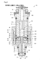
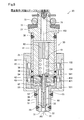
- FIG. 1 is an explanatory diagram showing a schematic configuration of an injector in the first embodiment.
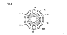
- FIG. 2 is a cross-sectional view of the needle taken along the line II-II in the first embodiment
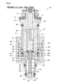
- FIG. 3 is a first explanatory view showing the valve opening operation of the injector in the first embodiment
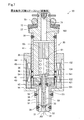
- FIG. 4 is a second explanatory view showing the valve opening operation of the injector in the first embodiment
- FIG. 5 is a third explanatory view showing the valve opening operation of the injector in the first embodiment
- FIG. 6 is a first explanatory view showing the valve closing operation of the injector in the first embodiment
- FIG. 1 is an explanatory diagram showing a schematic configuration of an injector in the first embodiment.
- FIG. 2 is a cross-sectional view of the needle taken along the line II-II in the first embodiment
- FIG. 3 is a first explanatory view showing the valve opening operation of the injector in the first embodiment
- FIG. 4 is a second explanatory view showing the valve opening operation of the
- FIG. 7 is a second explanatory view showing the valve closing operation of the injector in the first embodiment
- FIG. 8 is a third explanatory diagram showing the valve closing operation of the injector in the first embodiment
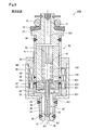
- FIG. 9 is an explanatory diagram showing a schematic configuration of the injector in the second embodiment.
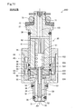
- FIG. 10 is an explanatory diagram showing a schematic configuration of an injector in the third embodiment.
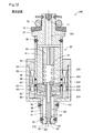
- FIG. 11 is an explanatory diagram showing a schematic configuration of an injector in the fourth embodiment.
- FIG. 12 is an explanatory diagram showing a schematic configuration of the injector in the fifth embodiment.
- FIG. 13 is an explanatory diagram showing grooves provided in the movable core in another embodiment.
- the injector 20 of the first embodiment includes a housing 30, a fixed core 41, a movable core 42, a coil 44, a needle 50, a first spring 61, a second spring 62, And an elastic member 55.
- the injector 20 is a device for injecting fuel.
- Injector 20 of this embodiment injects hydrogen gas which is gaseous fuel as fuel.
- the housing 30 is a cylindrical member in which a nozzle hole 32 for injecting fuel and a first flow path 101 communicating with the nozzle hole 32 are formed.
- the housing 30 of the present embodiment includes, in order from the nozzle hole 32 side, the nozzle tip part 31 in which the nozzle holes 32 are formed, the first magnetic part 34, the nonmagnetic part 36, the second magnetic part 35, and the inlet part. 37.
- a valve seat 33 is provided around the nozzle hole 32 on the inner surface of the housing 30 of the nozzle tip portion 31. Between the nozzle tip part 31 and the first magnetic part 34, between the first magnetic part 34 and the nonmagnetic part 36, between the nonmagnetic part 36 and the second magnetic part 35, and between the second magnetic part 35 and the inlet part.
- the nozzle tip portion 31 is made of martensitic stainless steel that is a nonmagnetic material.
- the first magnetic part 34 and the second magnetic part 35 are made of ferritic stainless steel, which is a magnetic material.
- the nonmagnetic portion 36 is formed of austenitic stainless steel that is a nonmagnetic material.
- a supply pipe (not shown) for supplying fuel to the injector 20 is connected to the inlet portion 37.
- the supply pipe is connected so as to contact a backup ring 72 provided at the inlet portion 37.
- a gap between the supply pipe and the inlet portion 37 is sealed by an O-ring 73 provided on the backup ring 72.
- An inlet channel 103 is formed in the inlet portion 37.
- a filter 71 is provided in the inlet channel 103. The filter 71 collects foreign matter contained in the fuel supplied from the supply pipe and suppresses the foreign matter from flowing into the housing 30.
- the fixed core 41 is a cylindrical member fixed in the housing 30.
- a second flow path 102 communicating with the first flow path 101 is formed in the fixed core 41.
- the opposite side of the second channel 102 from the first channel 101 communicates with the inlet channel 103.
- the fixed core 41 is made of a ferritic stainless steel that is a magnetic material.
- the movable core 42 is a cylindrical member provided so as to be capable of reciprocating along the axial direction AX of the housing 30 in the first flow path 101 closer to the injection hole 32 than the fixed core 41.
- the movable core 42 has an outer diameter larger than the inner diameter of the fixed core 41 and has a through hole 43 smaller than the inner diameter of the fixed core 41.
- the movable core 42 and the fixed core 41 are configured to be contactable in the axial direction AX.
- the movable core 42 is made of a ferritic stainless steel that is a magnetic material.
- the coil 44 is wound around the outer periphery of the housing 30.
- the outer periphery of the coil 44 is covered with a yoke 45 formed of ferritic stainless steel, which is a magnetic material.
- the coil 44 generates a magnetic field that moves the movable core 42 toward the fixed core 41 when energized.
- the current flowing through the coil 44 is supplied from, for example, a power supply source (not shown) such as a battery.
- the voltage applied from the power supply source is controlled by a control unit (not shown).
- the needle 50 includes a shaft portion 51, a valve portion 52, a stopper portion 53, and a flange portion 54.
- the stopper portion 53 may be referred to as a first protruding portion
- the flange portion 54 may be referred to as a second protruding portion.
- the shaft portion 51 is provided so as to reciprocate along the axial direction AX in the through hole 43 of the movable core 42.
- the central axis of the shaft portion 51 is the same as the central axis of the fixed core 41 and the central axis of the movable core 42.
- a communication channel 104 through which fuel flows from the second channel 102 toward the first channel 101 is formed inside the shaft portion 51.
- the valve part 52 is formed at the end of the shaft part 51 on the nozzle hole 32 side.
- the valve portion 52 is configured to be able to come into contact with a valve seat 33 provided in the nozzle tip portion 31, and is a valve body that opens and closes the injection hole 32 when the shaft portion 51 reciprocates along the axial direction AX. .
- the fuel that has flowed through the housing 30 in the order of the inlet channel 103, the second channel 102, the communication channel 104, and the first channel 101 is injected from the nozzle hole 32 when the nozzle hole 32 is opened. .
- the stopper part 53 is a disk-shaped member located on the valve part 52 side with respect to the movable core 42 in the shaft part 51.
- the stopper portion 53 protrudes larger than the diameter of the through hole 43 in the radial direction of the shaft portion 51.
- the stopper portion 53 has a first surface 531 on the fixed core 41 side.
- the stopper portion 53 is formed of austenitic stainless steel, which is a nonmagnetic material, and is press-fitted into the shaft portion 51.
- the flange portion 54 is a disk-shaped member that is positioned closer to the fixed core 41 than the movable core 42 in the shaft portion 51.
- the flange portion 54 protrudes in the radial direction of the shaft portion 51 larger than the diameter of the through hole 43 and smaller than the inner diameter of the fixed core 41.
- the flange portion 54 has a second surface 541 on the valve portion 52 side.
- the distance along the axial direction AX between the first surface 531 of the stopper portion 53 and the second surface 541 of the flange portion 54 is the axial direction AX between the third surface 421 of the movable core 42 and the fourth surface 422 of the movable core 42. Greater than the spacing along.
- the thickness of the movable core 42 is smaller than the distance along the axial direction AX between the first surface 531 of the stopper portion 53 and the second surface 541 of the flange portion 54.
- the shaft portion 51, the valve portion 52, and the flange portion 54 are integrally formed.
- the shaft portion 51, the valve portion 52, and the flange portion 54 are made of martensitic stainless steel, which is a nonmagnetic material.
- the first spring 61 is disposed in the second flow path 102.
- the first spring 61 urges the flange portion 54 from the fixed core 41 side toward the injection hole 32 side.
- the first spring 61 is a coil spring.
- An adjusting pipe 63 is provided upstream of the first spring 61 in the second flow path 102.
- the force with which the first spring 61 pushes the flange portion 54 is configured to be adjustable by adjusting the position of the end portion of the adjusting pipe 63 on the injection hole 32 side.
- the second spring 62 is disposed in the first flow path 101 and urges the movable core 42 from the injection hole 32 side toward the fixed core 41 side.
- the second spring 62 of the present embodiment is a coil spring. In the valve closed state, the movable core 42 is pushed by the second spring 62, and the second surface 541 of the flange portion 54 and the fourth surface 422 of the movable core 42 come into contact with each other.
- the elastic member 55 is provided on the first surface 531 of the stopper portion 53.
- the elastic member 55 of this embodiment is rubber.
- the rubber for example, fluorine rubber or silicon rubber can be used.
- the elastic member 55 is bonded to the first surface 531 by, for example, vulcanization bonding.
- the elastic member 55 is provided with a notch 56 extending from the inner peripheral side to the outer peripheral side of the elastic member 55.
- the cutout portion 56 is formed by adhering the elastic member 55 so that a part of the outer peripheral portion of the stopper portion 53 is exposed.
- the cutout portion 56 of this embodiment extends linearly from the inner peripheral side of the elastic member 55 toward the outer peripheral side.
- the form of the notch 56 may be any form in which foreign matter is easily discharged from the inner peripheral side of the elastic member 55 toward the outer peripheral side.
- a part of the outer peripheral portion of the stopper portion 53 is not exposed, and a groove from the inner peripheral side to the outer peripheral side of the elastic member 55 is formed on the elastic member 55, whereby the notch portion 56 is formed. Also good.
- valve opening operation performed in the injector 20 of the present embodiment will be described with reference to FIGS. 1 and 3 to 5.
- the valve portion 52 is in contact with the valve seat 33 in the valve closed state.
- the coil 44 is not energized.
- the flange portion 54 is pushed from the fixed core 41 side toward the nozzle hole 32 side by the first spring 61.
- the movable core 42 is pushed by the second spring 62 from the nozzle hole 32 side toward the fixed core 41 side. Therefore, the second surface 541 of the flange portion 54 and the fourth surface 422 of the movable core 42 are in contact with each other.
- a predetermined interval necessary for opening the valve is secured between the movable core 42 and the fixed core 41 in the valve-closed state. In this specification, this state is also referred to as an initial state.
- the needle 50 is detached from the movable core 42 due to inertia and continues to move toward the upstream side of the second flow path 102.
- the first surface 531 of the stopper portion 53 collides with the third surface 421 via the elastic member 55.
- the impact force caused by the collision between the first surface 531 of the stopper portion 53 and the third surface 421 of the movable core 42 is absorbed by the elastic member 55. Therefore, the impact force when the first surface 531 of the stopper portion 53 and the third surface 421 of the movable core 42 collide with each other is reduced.
- the impact force caused by the collision between the movable core 42 and the fixed core 41 is reduced when the needle 50 is detached from the movable core 42.
- the elastic energy stored in the first spring 61 is released as power to push back the needle 50.
- the needle 50 moves from the fixed core 41 side toward the injection hole 32 side, and the second surface 541 of the flange portion 54 collides with the fourth surface 422 of the movable core 42 again.
- the impact force when the first surface 531 of the stopper portion 53 and the third surface 421 of the movable core 42 collide with each other is reduced by the elastic member 55, so that the bounce of the needle 50 is suppressed and the flange portion 54.
- the impact force when the second surface 541 and the fourth surface 422 of the movable core 42 collide again is reduced. Thereafter, the second surface 541 of the flange portion 54 is supported by the fourth surface 422 of the movable core 42, thereby ensuring a lift amount between the valve portion 52 and the valve seat 33.
- the valve opening operation in the injector 20 is completed by the series of operations described above.
- FIG. 6 when the energization to the coil 44 is stopped, the magnetic attractive force from the fixed core 41 that has been working on the movable core 42 is unloaded and the needle biased by the first spring 61.
- the valve portion 52 collides with the valve seat 33 by moving 50 from the fixed core 41 side toward the nozzle hole 32 side. Therefore, the valve is closed and the fuel injection from the nozzle hole 32 is stopped.
- the needle 50 moves, the fourth surface 422 of the movable core 42 is pushed by the second surface 541 of the flange portion 54, so that the movable core 42 moves together with the needle 50.
- the movable core 42 continues to move from the fixed core 41 side toward the injection hole 32 side due to inertia, thereby moving the movable core 42.
- the third surface 421 collides with the first surface 531 of the stopper portion 53 via the elastic member 55.
- the impact force caused by the collision between the third surface 421 of the movable core 42 and the first surface 531 of the stopper portion 53 is absorbed by the elastic member 55. Therefore, the impact force when the first surface 531 of the stopper portion 53 and the third surface 421 of the movable core 42 collide with each other is reduced.
- the impact force due to the collision between the valve portion 52 and the valve seat 33 is reduced by the movement of the movable core 42 separately from the needle 50.
- the movable core 42 moves from the injection hole 32 side toward the fixed core 41 side by an impact force when the first surface 531 of the stopper portion 53 and the third surface 421 of the movable core 42 collide with each other.
- the second surface 541 of the flange portion 54 and the fourth surface 422 of the movable core 42 collide with each other.
- the impact force when the first surface 531 of the stopper portion 53 and the third surface 421 of the movable core 42 collide with each other is reduced by the elastic member 55, the rebound of the movable core 42 is suppressed, and the flange portion
- the impact force when the second surface 541 of 54 and the fourth surface 422 of the movable core 42 collide with each other is reduced.
- the movable core 42 is supported by the second spring 62 and returns to the initial state.
- the valve closing operation in the injector 20 is completed by the series of operations described above.
- the first surface 531 of the stopper portion 53 and the third surface 421 of the movable core 42 are in contact with each other via the elastic member 55, so the first surface of the stopper portion 53.
- the impact force when 531 and the third surface 421 of the movable core 42 collide with each other is reduced, and accordingly, the impact when the second surface 541 of the flange portion 54 and the fourth surface 422 of the movable core 42 collide with each other. Force is also reduced. Therefore, the wear of the movable core 42, the wear of the first protrusion 53 that contacts the movable core 42 via the elastic member 55, and the wear of the second protrusion 54 that contacts the movable core 42 can be suppressed.
- the injector 20 when the injector 20 is in the form of injecting gaseous fuel, the first surface 531 of the stopper portion 53 and the third surface 421 of the movable core 42, compared to the form of injecting liquid fuel, And since the squeeze force by the fuel when the 2nd surface 541 of the flange part 54 and the 4th surface 422 of the movable core 42 collide is small, an impact force becomes large. Therefore, the elastic member 55 has a great effect of suppressing the wear of the movable core 42, the first protrusion 53, and the second protrusion 54.
- the cutout portion 56 is provided in the elastic member 55, the discharge of foreign matters from the elastic member 55 is improved.
- the elastic member 55 passes through the filter 71 and enters the flow path. Even if foreign matter or foreign matter generated by wear in the flange portion 54 and the movable core 42 passes through the gap between the through hole 43 of the movable core 42 and the shaft portion 51 of the needle 50 and flows onto the elastic member 55, It is suppressed that the 1st surface 531 of the stopper part 53 and the 3rd surface 421 of the movable core 42 collide through a foreign material. Therefore, wear of the movable core 42 and the first protrusion 53 is further suppressed.
- the elastic member 55 is provided on the third surface 421 of the movable core 42 instead of the first surface 531 of the stopper 53. And different. Other configurations and opening / closing operations are the same as those in the first embodiment.
- the first surface 531 of the stopper portion 53 and the third surface 421 of the movable core 42 are in contact with each other via the elastic member 55, so that the first surface 531 of the stopper portion 53 and the movable core 42 are in contact with each other.
- the impact force when the third surface 421 collides is reduced, and accordingly, the impact force when the second surface 541 of the flange portion 54 collides with the fourth surface 422 of the movable core 42 is also reduced.
- the elastic member 55 is provided on both the first surface 531 of the stopper portion 53 and the third surface 421 of the movable core 42 in the first embodiment. Different from form. Other configurations and opening / closing operations are the same as those in the first embodiment.
- the injector 20C of this form since the elastic member 55 is provided on both the first surface 531 of the stopper portion 53 and the third surface 421 of the movable core 42, the first surface 531 of the stopper portion 53 is movable.
- the impact force when the third surface 421 of the core 42 collides is further reduced, and accordingly, the impact force when the second surface 541 of the flange portion 54 and the fourth surface 422 of the movable core 42 collide with each other. Reduced.
- the injector 20 ⁇ / b> D of the fourth embodiment is different from the first embodiment in that an elastic member 55 is also provided on the second surface 541 of the flange portion 54.
- the elastic member 55 may be provided on the fourth surface 422 of the movable core 42 instead of the second surface 541 of the flange portion 54, or the second surface 541 of the flange portion 54 and the fourth surface 422 of the movable core 42.
- the elastic member 55 may be provided in both.
- the second surface 541 of the flange portion 54 and the fourth surface 422 of the movable core 42 are in contact with each other via the elastic member 55, so the second surface 541 of the flange portion 54 and the movable core The impact force when colliding with the fourth surface 422 of 42 is further reduced.
- the injector 20E of the fifth embodiment is different from the first embodiment in that liquid fuel is injected as fuel. Further, the nozzle tip portion 31E is different from the first embodiment in that a plurality of nozzle holes 32 are provided. Other configurations and opening / closing operations are the same as those in the first embodiment. Examples of the liquid fuel include gasoline and light oil.
- the injector 20E of this form since it is a form which injects liquid fuel, compared with the form which injects gaseous fuel, the 1st surface 531 of the stopper part 53 and the 3rd surface 421 of the movable core 42 collide. At this time, the squeeze force by the fuel when the second surface 541 of the flange portion 54 and the fourth surface 422 of the movable core 42 collide with each other is increased, and the impact force is reduced.
- the elastic member 55 is provided with a notch 56.
- the elastic member 55 does not have to be provided with the notch 56.
- the contact area of the elastic member 55 is increased as compared with the configuration in which the notch portion 56 is provided. Therefore, the impact force when the first surface 531 of the stopper portion 53 and the third surface 421 of the movable core 42 collide is further reduced, and accordingly, the second surface 541 of the flange portion 54 and the first surface of the movable core 42 are reduced. The impact force when colliding with the four surfaces 422 is further reduced.
- the cutout portion 56 is provided in the elastic member 55 provided on the first surface 531 of the stopper portion 53.
- the groove 57 has a form extending linearly from the inner peripheral side to the outer peripheral side of the movable core 42.
- channel 57 should just be a form from which a foreign material is easy to be discharged
- the first surface 531 of the stopper portion 53 that is not provided with the elastic member 55 is the stopper portion 53. You may have the groove
- the elastic member 55 In the injector 20 in each of the embodiments described above, rubber is used as the elastic member 55.
- the elastic member 55 may be an elastic body other than rubber.
- a thermoplastic elastomer may be used.
- the elastic member 55 may be an elastic body that can reduce the impact force.
- the present disclosure is not limited to the above-described embodiment, and can be realized with various configurations without departing from the spirit of the present disclosure.
- the technical features in the embodiments are appropriately replaced or combined to solve part or all of the above-described problems or to achieve part or all of the above-described effects. Is possible.
- the technical feature is not described as essential in the present specification, it can be deleted as appropriate.
Landscapes
- Engineering & Computer Science (AREA)
- Chemical & Material Sciences (AREA)
- Combustion & Propulsion (AREA)
- Mechanical Engineering (AREA)
- General Engineering & Computer Science (AREA)
- Chemical Kinetics & Catalysis (AREA)
- General Chemical & Material Sciences (AREA)
- Oil, Petroleum & Natural Gas (AREA)
- Fuel-Injection Apparatus (AREA)
Applications Claiming Priority (2)
| Application Number | Priority Date | Filing Date | Title |
|---|---|---|---|
| JP2018091129A JP6733701B2 (ja) | 2018-05-10 | 2018-05-10 | インジェクタ |
| JP2018-091129 | 2018-05-10 |
Publications (1)
| Publication Number | Publication Date |
|---|---|
| WO2019216207A1 true WO2019216207A1 (ja) | 2019-11-14 |
Family
ID=68468050
Family Applications (1)
| Application Number | Title | Priority Date | Filing Date |
|---|---|---|---|
| PCT/JP2019/017253 Ceased WO2019216207A1 (ja) | 2018-05-10 | 2019-04-23 | インジェクタ |
Country Status (2)
| Country | Link |
|---|---|
| JP (1) | JP6733701B2 (enExample) |
| WO (1) | WO2019216207A1 (enExample) |
Cited By (2)
| Publication number | Priority date | Publication date | Assignee | Title |
|---|---|---|---|---|
| CN112983680A (zh) * | 2021-03-02 | 2021-06-18 | 北京航空航天大学 | 一种磁致伸缩材料驱动的针栓喷注器调节机构 |
| WO2025078548A1 (en) * | 2023-10-10 | 2025-04-17 | Phinia Delphi Luxembourg Sarl | Valve for a fuel injector |
Citations (4)
| Publication number | Priority date | Publication date | Assignee | Title |
|---|---|---|---|---|
| JP2003512557A (ja) * | 1999-10-21 | 2003-04-02 | ローベルト ボツシユ ゲゼルシヤフト ミツト ベシユレンクテル ハフツング | 燃料噴射弁 |
| JP2008038632A (ja) * | 2006-08-01 | 2008-02-21 | Aisan Ind Co Ltd | 燃料噴射弁 |
| JP2015021470A (ja) * | 2013-07-23 | 2015-02-02 | マツダ株式会社 | 燃料噴射弁 |
| JP2018059514A (ja) * | 2017-12-06 | 2018-04-12 | 株式会社デンソー | 燃料噴射弁 |
-
2018
- 2018-05-10 JP JP2018091129A patent/JP6733701B2/ja active Active
-
2019
- 2019-04-23 WO PCT/JP2019/017253 patent/WO2019216207A1/ja not_active Ceased
Patent Citations (4)
| Publication number | Priority date | Publication date | Assignee | Title |
|---|---|---|---|---|
| JP2003512557A (ja) * | 1999-10-21 | 2003-04-02 | ローベルト ボツシユ ゲゼルシヤフト ミツト ベシユレンクテル ハフツング | 燃料噴射弁 |
| JP2008038632A (ja) * | 2006-08-01 | 2008-02-21 | Aisan Ind Co Ltd | 燃料噴射弁 |
| JP2015021470A (ja) * | 2013-07-23 | 2015-02-02 | マツダ株式会社 | 燃料噴射弁 |
| JP2018059514A (ja) * | 2017-12-06 | 2018-04-12 | 株式会社デンソー | 燃料噴射弁 |
Cited By (2)
| Publication number | Priority date | Publication date | Assignee | Title |
|---|---|---|---|---|
| CN112983680A (zh) * | 2021-03-02 | 2021-06-18 | 北京航空航天大学 | 一种磁致伸缩材料驱动的针栓喷注器调节机构 |
| WO2025078548A1 (en) * | 2023-10-10 | 2025-04-17 | Phinia Delphi Luxembourg Sarl | Valve for a fuel injector |
Also Published As
| Publication number | Publication date |
|---|---|
| JP6733701B2 (ja) | 2020-08-05 |
| JP2019196739A (ja) | 2019-11-14 |
Similar Documents
| Publication | Publication Date | Title |
|---|---|---|
| US8684285B2 (en) | Fuel injection valve | |
| US7252245B2 (en) | Fuel injection valve | |
| JP4483940B2 (ja) | 燃料噴射弁 | |
| JP6753432B2 (ja) | 燃料噴射装置 | |
| US10941739B2 (en) | Fuel injection device | |
| JP5262972B2 (ja) | 燃料噴射弁 | |
| CN107709751A (zh) | 电磁阀 | |
| WO2016042753A1 (ja) | 燃料噴射弁 | |
| WO2019216207A1 (ja) | インジェクタ | |
| JP7323445B2 (ja) | 燃料噴射弁 | |
| JP4276954B2 (ja) | 燃料噴射弁 | |
| WO2017154815A1 (ja) | 燃料噴射装置 | |
| JP2013151915A (ja) | 燃料噴射弁 | |
| JP2002139168A (ja) | 電磁弁装置およびそれを用いた燃料噴射装置 | |
| CN107923548A (zh) | 电磁阀 | |
| US12110852B2 (en) | Fuel injection valve | |
| JP7152274B2 (ja) | 燃料噴射装置 | |
| US9394869B2 (en) | Fuel injector | |
| JP7273386B2 (ja) | インジェクタ | |
| WO2019216201A1 (ja) | インジェクタ | |
| JP6760422B2 (ja) | インジェクタ | |
| JP6338662B2 (ja) | 燃料噴射弁 | |
| JP7323444B2 (ja) | 燃料噴射弁 | |
| US20100038458A1 (en) | Fuel injector having an energy attenuator sub-assembly for the valve seat | |
| JP2006017088A (ja) | 燃料噴射弁 |
Legal Events
| Date | Code | Title | Description |
|---|---|---|---|
| 121 | Ep: the epo has been informed by wipo that ep was designated in this application |
Ref document number: 19798830 Country of ref document: EP Kind code of ref document: A1 |
|
| NENP | Non-entry into the national phase |
Ref country code: DE |
|
| 122 | Ep: pct application non-entry in european phase |
Ref document number: 19798830 Country of ref document: EP Kind code of ref document: A1 |