WO2019216096A1 - 粘着剤層、その製造方法、粘着シート、粘着剤層付光学フィルムおよび画像表示装置 - Google Patents
粘着剤層、その製造方法、粘着シート、粘着剤層付光学フィルムおよび画像表示装置 Download PDFInfo
- Publication number
- WO2019216096A1 WO2019216096A1 PCT/JP2019/015629 JP2019015629W WO2019216096A1 WO 2019216096 A1 WO2019216096 A1 WO 2019216096A1 JP 2019015629 W JP2019015629 W JP 2019015629W WO 2019216096 A1 WO2019216096 A1 WO 2019216096A1
- Authority
- WO
- WIPO (PCT)
- Prior art keywords
- adhesive layer
- pressure
- sensitive adhesive
- refractive index
- film
- Prior art date
- Legal status (The legal status is an assumption and is not a legal conclusion. Google has not performed a legal analysis and makes no representation as to the accuracy of the status listed.)
- Ceased
Links
Images



Classifications
-
- C—CHEMISTRY; METALLURGY
- C08—ORGANIC MACROMOLECULAR COMPOUNDS; THEIR PREPARATION OR CHEMICAL WORKING-UP; COMPOSITIONS BASED THEREON
- C08K—Use of inorganic or non-macromolecular organic substances as compounding ingredients
- C08K3/00—Use of inorganic substances as compounding ingredients
- C08K3/16—Halogen-containing compounds
-
- C—CHEMISTRY; METALLURGY
- C08—ORGANIC MACROMOLECULAR COMPOUNDS; THEIR PREPARATION OR CHEMICAL WORKING-UP; COMPOSITIONS BASED THEREON
- C08K—Use of inorganic or non-macromolecular organic substances as compounding ingredients
- C08K7/00—Use of ingredients characterised by shape
- C08K7/22—Expanded, porous or hollow particles
- C08K7/24—Expanded, porous or hollow particles inorganic
- C08K7/26—Silicon- containing compounds
-
- C—CHEMISTRY; METALLURGY
- C09—DYES; PAINTS; POLISHES; NATURAL RESINS; ADHESIVES; COMPOSITIONS NOT OTHERWISE PROVIDED FOR; APPLICATIONS OF MATERIALS NOT OTHERWISE PROVIDED FOR
- C09J—ADHESIVES; NON-MECHANICAL ASPECTS OF ADHESIVE PROCESSES IN GENERAL; ADHESIVE PROCESSES NOT PROVIDED FOR ELSEWHERE; USE OF MATERIALS AS ADHESIVES
- C09J11/00—Features of adhesives not provided for in group C09J9/00, e.g. additives
- C09J11/02—Non-macromolecular additives
- C09J11/04—Non-macromolecular additives inorganic
-
- C—CHEMISTRY; METALLURGY
- C09—DYES; PAINTS; POLISHES; NATURAL RESINS; ADHESIVES; COMPOSITIONS NOT OTHERWISE PROVIDED FOR; APPLICATIONS OF MATERIALS NOT OTHERWISE PROVIDED FOR
- C09J—ADHESIVES; NON-MECHANICAL ASPECTS OF ADHESIVE PROCESSES IN GENERAL; ADHESIVE PROCESSES NOT PROVIDED FOR ELSEWHERE; USE OF MATERIALS AS ADHESIVES
- C09J11/00—Features of adhesives not provided for in group C09J9/00, e.g. additives
- C09J11/08—Macromolecular additives
-
- C—CHEMISTRY; METALLURGY
- C09—DYES; PAINTS; POLISHES; NATURAL RESINS; ADHESIVES; COMPOSITIONS NOT OTHERWISE PROVIDED FOR; APPLICATIONS OF MATERIALS NOT OTHERWISE PROVIDED FOR
- C09J—ADHESIVES; NON-MECHANICAL ASPECTS OF ADHESIVE PROCESSES IN GENERAL; ADHESIVE PROCESSES NOT PROVIDED FOR ELSEWHERE; USE OF MATERIALS AS ADHESIVES
- C09J133/00—Adhesives based on homopolymers or copolymers of compounds having one or more unsaturated aliphatic radicals, each having only one carbon-to-carbon double bond, and at least one being terminated by only one carboxyl radical, or of salts, anhydrides, esters, amides, imides, or nitriles thereof; Adhesives based on derivatives of such polymers
- C09J133/04—Homopolymers or copolymers of esters
-
- C—CHEMISTRY; METALLURGY
- C09—DYES; PAINTS; POLISHES; NATURAL RESINS; ADHESIVES; COMPOSITIONS NOT OTHERWISE PROVIDED FOR; APPLICATIONS OF MATERIALS NOT OTHERWISE PROVIDED FOR
- C09J—ADHESIVES; NON-MECHANICAL ASPECTS OF ADHESIVE PROCESSES IN GENERAL; ADHESIVE PROCESSES NOT PROVIDED FOR ELSEWHERE; USE OF MATERIALS AS ADHESIVES
- C09J201/00—Adhesives based on unspecified macromolecular compounds
-
- C—CHEMISTRY; METALLURGY
- C09—DYES; PAINTS; POLISHES; NATURAL RESINS; ADHESIVES; COMPOSITIONS NOT OTHERWISE PROVIDED FOR; APPLICATIONS OF MATERIALS NOT OTHERWISE PROVIDED FOR
- C09J—ADHESIVES; NON-MECHANICAL ASPECTS OF ADHESIVE PROCESSES IN GENERAL; ADHESIVE PROCESSES NOT PROVIDED FOR ELSEWHERE; USE OF MATERIALS AS ADHESIVES
- C09J7/00—Adhesives in the form of films or foils
- C09J7/10—Adhesives in the form of films or foils without carriers
-
- C—CHEMISTRY; METALLURGY
- C09—DYES; PAINTS; POLISHES; NATURAL RESINS; ADHESIVES; COMPOSITIONS NOT OTHERWISE PROVIDED FOR; APPLICATIONS OF MATERIALS NOT OTHERWISE PROVIDED FOR
- C09J—ADHESIVES; NON-MECHANICAL ASPECTS OF ADHESIVE PROCESSES IN GENERAL; ADHESIVE PROCESSES NOT PROVIDED FOR ELSEWHERE; USE OF MATERIALS AS ADHESIVES
- C09J7/00—Adhesives in the form of films or foils
- C09J7/20—Adhesives in the form of films or foils characterised by their carriers
-
- C—CHEMISTRY; METALLURGY
- C09—DYES; PAINTS; POLISHES; NATURAL RESINS; ADHESIVES; COMPOSITIONS NOT OTHERWISE PROVIDED FOR; APPLICATIONS OF MATERIALS NOT OTHERWISE PROVIDED FOR
- C09J—ADHESIVES; NON-MECHANICAL ASPECTS OF ADHESIVE PROCESSES IN GENERAL; ADHESIVE PROCESSES NOT PROVIDED FOR ELSEWHERE; USE OF MATERIALS AS ADHESIVES
- C09J7/00—Adhesives in the form of films or foils
- C09J7/30—Adhesives in the form of films or foils characterised by the adhesive composition
-
- C—CHEMISTRY; METALLURGY
- C09—DYES; PAINTS; POLISHES; NATURAL RESINS; ADHESIVES; COMPOSITIONS NOT OTHERWISE PROVIDED FOR; APPLICATIONS OF MATERIALS NOT OTHERWISE PROVIDED FOR
- C09J—ADHESIVES; NON-MECHANICAL ASPECTS OF ADHESIVE PROCESSES IN GENERAL; ADHESIVE PROCESSES NOT PROVIDED FOR ELSEWHERE; USE OF MATERIALS AS ADHESIVES
- C09J7/00—Adhesives in the form of films or foils
- C09J7/30—Adhesives in the form of films or foils characterised by the adhesive composition
- C09J7/38—Pressure-sensitive adhesives [PSA]
-
- G—PHYSICS
- G02—OPTICS
- G02B—OPTICAL ELEMENTS, SYSTEMS OR APPARATUS
- G02B5/00—Optical elements other than lenses
- G02B5/30—Polarising elements
-
- C—CHEMISTRY; METALLURGY
- C08—ORGANIC MACROMOLECULAR COMPOUNDS; THEIR PREPARATION OR CHEMICAL WORKING-UP; COMPOSITIONS BASED THEREON
- C08K—Use of inorganic or non-macromolecular organic substances as compounding ingredients
- C08K3/00—Use of inorganic substances as compounding ingredients
- C08K3/16—Halogen-containing compounds
- C08K2003/162—Calcium, strontium or barium halides, e.g. calcium, strontium or barium chloride
-
- C—CHEMISTRY; METALLURGY
- C08—ORGANIC MACROMOLECULAR COMPOUNDS; THEIR PREPARATION OR CHEMICAL WORKING-UP; COMPOSITIONS BASED THEREON
- C08K—Use of inorganic or non-macromolecular organic substances as compounding ingredients
- C08K3/00—Use of inorganic substances as compounding ingredients
- C08K3/16—Halogen-containing compounds
- C08K2003/166—Magnesium halide, e.g. magnesium chloride
-
- C—CHEMISTRY; METALLURGY
- C09—DYES; PAINTS; POLISHES; NATURAL RESINS; ADHESIVES; COMPOSITIONS NOT OTHERWISE PROVIDED FOR; APPLICATIONS OF MATERIALS NOT OTHERWISE PROVIDED FOR
- C09J—ADHESIVES; NON-MECHANICAL ASPECTS OF ADHESIVE PROCESSES IN GENERAL; ADHESIVE PROCESSES NOT PROVIDED FOR ELSEWHERE; USE OF MATERIALS AS ADHESIVES
- C09J2301/00—Additional features of adhesives in the form of films or foils
- C09J2301/40—Additional features of adhesives in the form of films or foils characterized by the presence of essential components
- C09J2301/408—Additional features of adhesives in the form of films or foils characterized by the presence of essential components additives as essential feature of the adhesive layer
Definitions
- the present invention relates to an adhesive layer and a method for producing the same. Moreover, this invention relates to the adhesive sheet which has the said adhesive layer, and an optical film with an adhesive layer. Furthermore, the present invention relates to an image display device using them.
- a display device such as a liquid crystal display device or an organic EL display device has a pressure-sensitive adhesive composition for bonding a polarizing film, a retardation film, a transparent cover member such as a cover glass, and other various optical films to other optical films.
- an optical film laminate having the two optical films is formed by disposing the pressure-sensitive adhesive layer between the two optical films.
- the optical film laminate having such a configuration is disposed, for example, such that the optical film side is the viewing side.
- the incident light is reflected at the interface between the adhesive layer and the non-viewing-side optical film and returns to the viewing side. This problem is particularly noticeable when the incident angle of external light is shallow.
- a backlight unit of an image display device for example, it has been proposed to use a light diffusion pressure-sensitive adhesive composition containing a (meth) acrylic polymer as a base polymer and containing light diffusing fine particles (Patent Literature). 1).
- the problem as described above is considered to be caused by the difference in refractive index between the pressure-sensitive adhesive layer and the adherend.
- an optical member for example, an antireflection film, a light diffusion film, a light guide film
- a low refractive index material such as an adhesive layer and a fluorine-based resin, polysiloxane, low refractive inorganic particles, porous material, hollow material, etc.
- a prism film, a lens film, a Fresnel lens, a lenticular lens, or a micro lens film a problem arises in visibility due to the internal reflection of incident light at the interface.
- a pressure-sensitive adhesive layer having a low refractive index As a method of forming a pressure-sensitive adhesive layer having a low refractive index with an acrylic pressure-sensitive adhesive, a general acrylic polymer (refractive index is usually 1.47 to 1.52) which is a base polymer and a fluorocarbon monomer unit are used. It is conceivable to use alkyl acrylate (refractive index of around 1.38).
- an adhesive layer having a low refractive index using a base polymer containing the fluoroalkyl acrylate as a monomer unit has a high surface tension and it is difficult to ensure adhesion.
- a pressure-sensitive adhesive layer having a low refractive index for example, a refractive index of 1.40 or less
- the pressure-sensitive adhesive layer formed from the light diffusing pressure-sensitive adhesive composition of Patent Document 1 has a light diffusing function, but the light diffusing fine particles are dispersed in the entire range of the pressure-sensitive adhesive layer. It is difficult to ensure sufficient adhesion with the like.
- the present invention can effectively suppress internal reflection even when applied to an optical member having a low refractive index such as an antireflection film, a light diffusion film, a lens film, a Fresnel lens, a lenticular lens, or a microlens film. And it aims at providing the adhesive layer with favorable adhesiveness, and its manufacturing method.
- an optical member having a low refractive index such as an antireflection film, a light diffusion film, a lens film, a Fresnel lens, a lenticular lens, or a microlens film.
- this invention provides the adhesive sheet which has the said adhesive layer, Furthermore, it provides the optical film with an adhesive layer which has the said adhesive layer, Furthermore, this invention is with the said adhesive layer or an adhesive layer.
- An object of the present invention is to provide an image display device having an optical film.
- the present invention is a pressure-sensitive adhesive layer having a first surface and a second surface opposite to the first surface,
- the pressure-sensitive adhesive layer forms the base of the entire pressure-sensitive adhesive layer by a pressure-sensitive adhesive composition containing a base polymer,
- the first surface has a first refractive index based on the pressure-sensitive adhesive composition, while the second refractive index of the second surface is lower than the first refractive index of the first surface.
- Agent layer is a pressure-sensitive adhesive layer having a first surface and a second surface opposite to the first surface,
- the pressure-sensitive adhesive layer forms the base of the entire pressure-sensitive adhesive layer by a pressure-sensitive adhesive composition containing a base polymer,
- the first surface has a first refractive index based on the pressure-sensitive adhesive composition, while the second refractive index of the second surface is lower than the first refractive index of the first surface.
- Agent layer is a pressure-sensitive adhesive layer having a first surface and a second surface opposite to the first surface,
- the difference between the first refractive index of the first surface and the second refractive index of the second surface is preferably 0.02 to 0.45.
- the second refractive index of the second surface is preferably 1.45 or less.
- the pressure-sensitive adhesive layer it is possible to adopt a mode in which a low refractive index material having a refractive index lower than the refractive index of the base polymer is dispersed on the second surface side.
- the thickness of the region in which the low refractive index material is dispersed is preferably 600 nm or less in the thickness direction from the second surface side in the pressure-sensitive adhesive layer.
- the base polymer preferably has a refractive index of 1.40 to 1.55, and the low refractive material has a refractive index of 1.10 to 1.45.
- the difference between the refractive index of the base polymer and the refractive index of the low refractive index material is preferably 0.07 to 0.45.
- Examples of the low refractive index material include particles having an average particle diameter of 10 nm to 150 nm.
- the low refractive index material is selected from the group consisting of at least one inorganic particle selected from the group consisting of MgF 2 , CaF 2 and Na 3 AlF 6 , porous silica particles, hollow nanosilica particles, and hollow polymer particles. At least one particle.
- the pressure-sensitive adhesive layer preferably has a total light transmittance of 85% or more.
- the adhesive layer preferably has a reflectance of 0.5 to 3.5% on the second surface.
- the difference in reflectance between the first surface and the second surface is preferably 0.1 to 3.5%.
- the pressure-sensitive adhesive layer preferably has a gel fraction of 30 to 95% by weight.
- the pressure-sensitive adhesive layer preferably has a storage elastic modulus G ′ at 25 ° C. of 0.05 to 0.50 MPa.
- the pressure-sensitive adhesive layer preferably has a tan ⁇ peak value of ⁇ 5 to ⁇ 50 ° C. when measuring dynamic viscoelasticity at 1 Hz.
- the present invention is also a method for producing the pressure-sensitive adhesive layer, Forming a base pressure-sensitive adhesive layer on the support with a pressure-sensitive adhesive composition containing the base polymer (1), Preparing a dispersion in which a low refractive index material having a lower refractive index than that of the base polymer is dispersed (2); In the base adhesive layer, the dispersion or solution is applied to the second surface opposite to the first surface on the support side, and the low refractive index material contained in the dispersion or solution is applied to the base adhesive.
- a step (3) of infiltrating in the thickness direction from the second surface of the agent layer, and a step (4) of drying the adhesive layer infiltrated with the low refractive index material It is related with the manufacturing method of the adhesive layer characterized by including.
- the present invention also relates to the pressure-sensitive adhesive layer and the pressure-sensitive adhesive sheet having a support on one side or both sides of the pressure-sensitive adhesive layer.
- the present invention is an optical film with an adhesive layer having an optical film and an adhesive layer provided on one side or both sides of the optical film,
- the single-sided or double-sided pressure-sensitive adhesive layer is the pressure-sensitive adhesive layer, and the first surface side of the pressure-sensitive adhesive layer is provided on the optical film.
- a polarizing film is preferably used as the optical film.
- the present invention also relates to an optical laminate comprising the optical film with the pressure-sensitive adhesive layer and a low refractive index optical member bonded to the pressure-sensitive adhesive layer of the optical film with the pressure-sensitive adhesive layer.
- the present invention also relates to an image display device comprising the pressure-sensitive adhesive layer, the optical film with the pressure-sensitive adhesive layer, or the optical laminate.
- the pressure-sensitive adhesive layer of the present invention is different from the diffusion pressure-sensitive adhesive layer in which fine particles are uniformly diffused in the pressure-sensitive adhesive layer, and has different refractive indexes on both sides of a single pressure-sensitive adhesive layer having a first surface and a second surface.
- the first surface side has a first refractive index based on the pressure-sensitive adhesive composition that forms the base of the entire pressure-sensitive adhesive layer, and the other second surface side has the first refractive index.
- the second refractive index is lower than the first refractive index of the surface.
- the pressure-sensitive adhesive layer of the present invention has a pressure-sensitive adhesive surface controlled to have a lower refractive index than the refractive index based on the pressure-sensitive adhesive layer
- an optical member formed of a low refractive index material for example, The refractive index difference between the antireflection film, light diffusion film, light guide film, prism film, lens film, Fresnel lens, lenticular lens, microlens film, etc.
- Reflection at the interface with the optical member can be suppressed, and the light extraction efficiency can be improved.
- the second surface of the pressure-sensitive adhesive layer of the present invention When the second surface of the pressure-sensitive adhesive layer of the present invention is applied to a surface uneven shape portion such as a microlens, the surface uneven shape is protected by filling the surface uneven shape portion with the pressure-sensitive adhesive layer. Compared to the case where a void layer is provided on the surface uneven shape portion, the void can be filled without impairing the light extraction efficiency, and scratches and shape damage due to vibration during handling and transportation can be achieved. Can be suppressed. Further, the second surface of the pressure-sensitive adhesive layer of the present invention has a refractive index adjustment region adjusted to a low refractive index, but has a high total light transmittance and a low refractive index region without increasing the haze value. Can be formed.
- the adhesive layer of this invention since the adhesive force which the adhesive layer originally has is maintained, adhesiveness with a general optical film (for example, polarizing film etc.) is also favorable, on the other hand, since the pressure-sensitive adhesive composition forms a base also on the second surface of the pressure-sensitive adhesive layer controlled to have a low refractive index, it ensures adhesion with an optical film formed of a low-refractive index material. Can do.
- a general optical film for example, polarizing film etc.
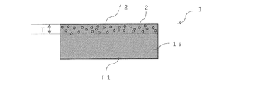
- the pressure-sensitive adhesive layer 1 of the present invention has a first surface f1 and a second surface f2 on the opposite side of the first surface f1.
- substrate (matrix) 1a of the adhesive layer 1 whole is formed with the adhesive composition containing a base polymer.
- the first surface f1 has a first refractive index n1
- the second refractive index n2 of the second surface f2 is designed to be lower than the first refractive index n1.
- FIG. 1 illustrates a case where a low refractive index material 2 having a refractive index lower than the refractive index of the base polymer is dispersed (distributed) on the base 1a on the second surface f2 side. ing.
- the first refractive index n1 of the first surface f1 corresponds to the refractive index of the pressure-sensitive adhesive layer obtained from the pressure-sensitive adhesive composition forming the base 1a in the pressure-sensitive adhesive layer 1 of the present invention. Accordingly, the first refractive index n1 is determined by the pressure-sensitive adhesive composition forming the base 1a. In addition, since the refractive index of the base polymer is substantially the same as the refractive index of the base 1a adhesive layer 1 of the entire adhesive layer 1, the first refractive index n1 of the first surface f1 is approximately the base. Determined by the refractive index of the polymer.
- the pressure-sensitive adhesive composition forming the pressure-sensitive adhesive layer will be described later.
- the refractive index of a pressure-sensitive adhesive layer formed of a typical acrylic pressure-sensitive adhesive is generally about 1.47 to 1.52.
- the refractive index of the pressure-sensitive adhesive layer formed of the silicone-based pressure-sensitive adhesive is generally about 1.40.
- the second refractive index n2 of the second surface f2 is not particularly limited as long as n1> n2 is satisfied in relation to the first refractive index n1 on the first surface f1 side. It is appropriately determined in consideration of the refractive index of the low refractive index optical film. However, if the difference (n1 ⁇ n2) between the first refractive index n1 and the second refractive index n2 becomes too large, internal reflection in the pressure-sensitive adhesive layer 1 may occur. ) Is preferably adjusted to 0.02 to 0.45.
- the difference (n1-n2) is more preferably 0.03 to 0.35, and further preferably 0.03 to 0.25.
- the second refractive index n2 of the second surface f2 is preferably, for example, 1.45 or less from the viewpoint of effectively suppressing internal reflection, more preferably 1.4 or less, and further 1 Is preferably 35 or less, and more preferably 1.3 or less. If the second refractive index n2 is 1.4 or less, the second surface side of the pressure-sensitive adhesive layer 1 of the present invention can be used as an alternative to the air layer. On the other hand, the second refractive index n2 is preferably 1.25 or more, and more preferably 1.28 or more, from the viewpoint of maintaining adhesive force.
- the range of the second refractive index n2 is a range lower than the lower limit value of the refractive index (generally about 1.47 to 1.52) of the pressure-sensitive adhesive layer formed of a typical acrylic pressure-sensitive adhesive.
- the base polymer in the pressure-sensitive adhesive composition forming the base 1a is dispersed.
- the refractive index is 1.40 to 1.55, and the refractive index of the low refractive index material 2 dispersed on the second surface a2 side in the substrate 1a is 1.10 to 1.45. preferable.
- the difference between the refractive index of the base polymer and the refractive index of the low refractive index material 2 is preferably 0.07 to 0.45.
- the refractive index of the base polymer is more preferably 1.40 to 1.52, and further preferably 1.40 to 1.50.
- the refractive index of the low refractive index material 2 is preferably 1.14 to 1.42, and more preferably 1.18 to 1.40.
- the difference between the refractive index of the base polymer and the refractive index of the low refractive index material 2 is preferably 0.07 to 0.35, and more preferably 0.10 to 0.30.
- the low refractive index material 2 has a lower refractive index, and the refractive index can be lowered with a small addition amount.
- the difference between the refractive index of the base polymer (adhesive layer 1a) and the refractive index of the low refractive index material 2 is low.
- the refractive index difference is preferably adjusted so as not to become too large.
- the refractive index can be shown as a refractive index value of D line measured in a 23 ° C. environment by spectroscopic ellipsometry when the material is a single layer film.
- particles having an average particle diameter of 10 nm to 150 nm can be used. Particles having an average particle diameter in the above range are preferable for keeping the haze of the pressure-sensitive adhesive layer 1 low and maintaining a high total light transmittance even when dispersed on the second surface f2 side of the pressure-sensitive adhesive layer 1. .
- the average particle diameter is preferably 20 nm to 100 nm, more preferably 20 nm to 90 nm.
- the average particle diameter of the particles is a value measured by a particle size distribution diameter measuring apparatus using a dynamic light scattering method.
- low refractive index material 2 examples include MgF 2 (refractive index 1.38), CaF 2 (refractive index 1.43: fluorite), Na 3 AlF (refractive index 1.34: sodium hexafluoroaluminate ( Cryolite)) and the like. These materials (for example, particles) can be used alone or in combination of two or more.
- the low refractive index material 2 for example, hollow particles can be used.
- the hollow particles may be inorganic particles or polymer particles. Since the hollow particles have a void space having a low refractive index in the particles, the refractive index of the hollow particles is lower than the refractive index of the component forming the hollow particles.
- silica has a refractive index of 1.46, but hollow nanosilica particles (refractive index: 1.24, trade name: thruria 5320, particle size 75 nm, manufactured by JGC Catalysts & Chemicals Co., Ltd.), porous silica particles have low refractive index. It can be used as a material.
- the hollow particles include fine hollow polymer particles (refractive index: 1.32, trade name: Techpolymer NH, product number XX-255AA, particle size 80 nm, hollow rate 39%, manufactured by Sekisui Plastics Co., Ltd.).
- the hollow particles when the hollow particles are provided on the surface treatment layer having a low refraction, the hollow particles (low refractive index material 2) in the present invention have a problem in strength and scratch resistance because they are hollow materials. Since it is a form added (impregnated) in the agent layer 1, it can be applied without considering the problems of strength and scratch resistance.
- an oligomer containing a fluoroalkyl group, an oligomer of a polysiloxane resin, or the like can be used as the low refractive index material 2.
- the thickness of the pressure-sensitive adhesive layer 1 is not particularly limited, but is usually 5 ⁇ m to 500 ⁇ m, preferably 10 ⁇ m to 400 ⁇ m, and more preferably 10 ⁇ m to 350 ⁇ m.
- distributing in the said adhesive layer 1 is represented by thickness T from the said 2nd surface f2 side.
- the thickness T is appropriately designed according to the thickness of the pressure-sensitive adhesive layer, but is usually preferably 600 nm or less, more preferably 300 nm or less, and further preferably 200 nm or less.
- the thickness T is preferably 10 nm or more, more preferably 15 nm or more, and more preferably 20 nm or more in order to effectively suppress internal reflection when applied to an optical film having a low refractive index. Is preferred.
- the region where the low refractive index material 2 relating to the thickness T is dispersed in the pressure-sensitive adhesive layer 1 has an irregular concavo-convex shape in relation to the base (matrix) 1a. Is determined by averaging the measured values of the depth of the concavo-convex shape.
- the low refractive index material 2 is distributed on the second surface f2 side in a dispersed state or in a partially aggregated state.
- the boundary between the region where the low-refractive index material 2 is dispersed and the base 1a where the low-refractive index material 2 is not dispersed has an irregular uneven shape as described with reference to FIG.
- the range of the depth where 90% of the low refractive index material 2 exists at each measurement position is taken as the measurement value of the thickness T at the measurement position, and the measurement values at a plurality of measurement positions are used. Average.
- FIG. 2 is a plan view showing a state of the second surface f2 of the pressure-sensitive adhesive layer 1.
- the base 1a has a sea-island structure in which the low refractive index material 2 is dispersed in an island shape.
- the base 1a portion and the low refractive index material 2 portion exist.
- the area ratio of the low refractive index material 2 on the second surface f2 is preferably in the range of 30 to 99%.
- the area ratio is the ratio of the area occupied by the low refractive index material 2 to the total area of the square area in a square area having a side of 10 ⁇ m to 200 ⁇ m, and measurement is performed for a plurality of square areas, and the measured values are averaged. An area ratio is required.
- the ratio of the low refractive index material 3 in the pressure-sensitive adhesive layer 1 is such that the first refractive index n1 on the first surface f1 side and the second refractive index n2 on the second surface f2 satisfy the relationship n1> n2. If it does, it will not be restricted in particular.
- the total light transmittance of the entire pressure-sensitive adhesive layer 1 of the present invention is preferably 85% or more, more preferably 88% or more, and further preferably 90% or more.
- the total light transmittance of the pressure-sensitive adhesive layer 1 is preferably as high as possible.
- the haze value is preferably 1.5% or less, more preferably 1% or less, and still more preferably 0.8% or less.
- the haze value of the pressure-sensitive adhesive layer 1 is preferably as low as possible.
- the total light transmittance and haze value of the entire pressure-sensitive adhesive layer 1 are values measured in accordance with JIS K7361.
- the reflectance of the second surface of the pressure-sensitive adhesive layer 1 of the present invention is preferably 0.5 to 3.5%.
- the reflectance of the second surface of the pressure-sensitive adhesive layer 1 of the present invention is lower than the reflectance of the first surface, and the internal reflection can be controlled to be small even in relation to the low refractive index material.
- the reflectance of the two surfaces is preferably 0.5 to 3.0%, more preferably 0.5 to 2.5%.
- the difference in reflectance between the first surface and the second surface of the pressure-sensitive adhesive layer 1 of the present invention is preferably 0.1 to 3.5%.
- the pressure-sensitive adhesive layer 1 of the present invention is described above on the assumption that the second refractive index n2 of the second surface f2 is designed to be lower than the first refractive index n1.
- the pressure-sensitive adhesive layer 1 of the present invention can be specified by the relationship between the refractive indexes of both surfaces, and the reflectance of the second surface f2 is lower than the reflectance of the first surface f1. It can be understood as a featured invention.
- the pressure-sensitive adhesive layer 1 of the present invention preferably has a gel fraction of 30 to 95% by weight.
- the gel fraction is preferably 30 to 90% by weight, more preferably 35 to 90% by weight, and still more preferably 40 to 90% by weight.
- the gel fraction relates to the base 1a in the pressure-sensitive adhesive layer 1 and does not include the low refractive index material 2.
- Sample 1 was scraped about 0.2 g from the pressure-sensitive adhesive layer (before penetration of the low refractive index material).
- the sample 1 was wrapped in a Teflon (registered trademark) film (trade name “NTF1122”, manufactured by Nitto Denko Corporation) having a diameter of 0.2 ⁇ m, and then tied with a kite string to obtain a sample 2.
- the weight of sample 2 before being subjected to the following test was measured, and this was designated as weight A.
- the weight A is the total weight of the sample 1 (adhesive layer), the Teflon (registered trademark) film, and the kite string.
- the total weight of the Teflon (registered trademark) film and the kite string was defined as weight B.
- the pressure-sensitive adhesive layer 1 of the present invention preferably has a storage elastic modulus G ′ at 25 ° C. of 0.05 to 0.50 MPa.
- the storage elastic modulus G ′ is preferably 0.06 to 0.45 MPa, more preferably 0.07 to 0.40 MPa, and still more preferably 0.08 to 0.35 MPa.
- image display devices LCD, OLED terminals, etc.
- the pressure-sensitive adhesive layer 1 of the present invention preferably has a tan ⁇ peak value (glass transition temperature) of ⁇ 5 to ⁇ 50 ° C. when measuring dynamic viscoelasticity at 1 Hz.
- the tan ⁇ peak value is preferably ⁇ 7 to ⁇ 50 ° C., more preferably ⁇ 9 to ⁇ 45 ° C., and further preferably ⁇ 10 to ⁇ 40 ° C.
- the tan ⁇ peak value of the pressure-sensitive adhesive layer 1 is within the above range, it becomes a preferable aspect in securing the resistance against a drop impact of the image display device (mobile terminal or the like).
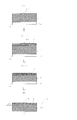
- a base pressure-sensitive adhesive layer 1 ′ is formed on a support S with a pressure-sensitive adhesive composition containing a base polymer.
- Base adhesive layer 1 ' forms the base
- the support 1 side is the first surface f1 ′, and the opposite side is the second surface f2 ′.
- the method for forming the base pressure-sensitive adhesive layer 1 ′ is not particularly limited, and can be formed by a method usually used in this field. Specifically, the pressure-sensitive adhesive composition is applied to one side of the support S and a coating film formed from the pressure-sensitive adhesive composition is formed by drying, or irradiated with active energy rays such as ultraviolet rays. Can be formed.
- the support S is not particularly limited, and various substrates such as a release film and a transparent resin film substrate can be used.
- the constituent material of the release film examples include resin films such as polyethylene, polypropylene, polyethylene terephthalate, and polyester films, porous materials such as paper, cloth, and nonwoven fabric, nets, foam sheets, metal foils, and laminates thereof. Suitable thin leaf bodies and the like can be mentioned, but a resin film is suitably used from the viewpoint of excellent surface smoothness.
- the release film may be subjected to release and antifouling treatment or antistatic treatment as necessary.
- a dispersion 10 in which a low refractive index material 2 having a refractive index lower than the refractive index of the base polymer used in the pressure-sensitive adhesive composition is prepared (not shown).
- a dispersion medium used in the dispersion a material capable of dispersing the low refractive index material 2 and penetrating into the base pressure-sensitive adhesive layer 1 ′ is used. It is selected in a timely manner according to the type of pressure-sensitive adhesive composition forming the layer.
- the concentration of the low refractive index material in the dispersion medium is preferably adjusted to 0.1 to 10% by weight, for example.
- dispersion medium examples include methanol, ethanol, isopropyl alcohol, 1-propanol, n-butanol, 2-butanol, cyclohexanol, t-butyl alcohol, glycerin, ethylene glycol, 2-methyl-2,4-pentadiol.
- Alcohols such as phenol and parachlorophenol; ketones such as acetone, methyl ethyl ketone, methyl isobutyl ketone, cyclohexanone, cyclopentanone, 2-pentanone, 2-hexanone, 2-heptanone; diethyl ether, tetrahydrofuran, dioxane, anisole, etc.
- Ethers such as ethyl acetate, butyl acetate and methyl lactate; aromatic hydrocarbons such as benzene, toluene and xylene; aliphatic hydrocarbons such as n-hexane and cyclohexane; Chill formamide, amides such as dimethylacetamide; methyl cellosolve, ethyl cellosolve, cellosolve such as methyl cellosolve acetate and the like.
- These dispersion media can be used alone or in admixture of two or more.
- said solvent is a mere illustration and the solvent used for this invention is not limited to these.
- the dispersion 10 is applied to the second surface f2 ′ of the base adhesive layer 1 ′, and the low refractive index material 2 contained in the dispersion 10 is applied to the base adhesive. It penetrates in the thickness direction from the second surface f2 ′ of the agent layer 1 ′.
- (3) -1 in FIG. 3 shows a state immediately after the dispersion 10 is coated with the base pressure-sensitive adhesive layer 1 ′, and (3) -2 shows a state in which the low refractive index material 2 has penetrated the base pressure-sensitive adhesive layer 1 ′.
- the second surface f2 ′ side of the base pressure-sensitive adhesive layer 1 ′ is swollen by the dispersion medium of the dispersion liquid 10, and in the process, the low refractive index material 2 in the dispersion liquid 10 enters the base pressure-sensitive adhesive layer 1 ′. To penetrate.
- the base pressure-sensitive adhesive layer 1 ′ into which the low refractive index material 2 has penetrated is dried.
- the pressure-sensitive adhesive layer 1 shown in FIG. 1 can be obtained by evaporating the dispersion medium of the dispersion 10 that has penetrated into the base pressure-sensitive adhesive layer 1 ′ by the drying step. This state is shown in (4) of FIG.
- the conditions for the drying step are determined according to the type of the dispersion medium.
- the region (thickness T) in which the low refractive index material 2 is dispersed in the pressure-sensitive adhesive layer 1 is determined by the relationship between the pressure-sensitive adhesive composition forming the base pressure-sensitive adhesive layer 1 ′ and the dispersion medium of the dispersion liquid 10. .
- the dispersion medium can be appropriately selected so that the penetration depth becomes the value described above. Further, the coating amount of the dispersion liquid is appropriately set so as to have a desired thickness T.
- the dispersion can be applied by, for example, roll coating, kiss roll coating, gravure coating, reverse coating, roll brushing, spray coating, dip roll coating, bar coating, knife coating, air knife coating, curtain coating, lip coating, or die coating.
- An appropriate method such as a filter can be used.
- the thickness T can be controlled by the dispersion coating method, the concentration of the dispersion, the coating amount, and the like.
- ⁇ Adhesive composition The pressure-sensitive adhesive composition containing the base polymer that forms the base (matrix) 1a of the pressure-sensitive adhesive layer 1 of the present invention will be described.
- the adhesive composition is preferably a transparent material having adhesiveness that can be used for optical applications.
- the pressure-sensitive adhesive composition is appropriately selected from, for example, acrylic pressure-sensitive adhesives, rubber-based pressure-sensitive adhesives, silicone-based pressure-sensitive adhesives, polyester-based pressure-sensitive adhesives, urethane-based pressure-sensitive adhesives, epoxy-based pressure-sensitive adhesives, and polyether-based pressure-sensitive adhesives. Can be used. From the viewpoint of transparency, workability, durability, etc., it is preferable to use an acrylic pressure-sensitive adhesive. A base polymer corresponding to the type of the pressure-sensitive adhesive composition is used. In the present invention, an acrylic pressure-sensitive adhesive containing a (meth) acrylic polymer as a base polymer is preferable.
- the acrylic pressure-sensitive adhesive can include, for example, a partial polymer of a monomer component containing alkyl (meth) acrylate and / or a (meth) acrylic polymer obtained from the monomer component.
- the base polymer of the acrylic pressure-sensitive adhesive includes a partial polymer of a monomer component containing an alkyl (meth) acrylate and / or a (meth) acrylic polymer obtained from the monomer component.
- alkyl (meth) acrylate examples include the aforementioned linear or branched alkyl (meth) acrylates having 1 to 24 carbon atoms, and among these, alkyl (meth) having 1 to 9 carbon atoms. Acrylates are preferred, and alkyl (meth) acrylates having 4 to 9 carbon atoms are preferred.
- the alkyl (meth) acrylate is preferable in terms of easily balancing the adhesive properties.
- Specific examples of the alkyl (meth) acrylate having 4 to 9 carbon atoms include n-butyl (meth) acrylate, s-butyl (meth) acrylate, t-butyl (meth) acrylate, and isobutyl (meth).
- n-pentyl (meth) acrylate isopentyl (meth) acrylate, isohexyl (meth) acrylate, isoheptyl (meth) acrylate, 2-ethylhexyl (meth) acrylate, isooctyl (meth) acrylate, isononyl (meth) acrylate, etc.
- These can be used alone or in combination of two or more.
- the alkyl (meth) acrylate having an alkyl group having 1 to 24 carbon atoms at the ester terminal is 40% by weight or more based on the total amount of the monofunctional monomer component forming the (meth) acrylic polymer. It is preferably 50% by weight or more, more preferably 60% by weight or more.
- the monomer component may contain a copolymerization monomer other than the alkyl (meth) acrylate as a monofunctional monomer component.
- a copolymerization monomer can be used as the remainder of the said alkyl (meth) acrylate in a monomer component.
- a cyclic nitrogen-containing monomer can be included.
- a polymerizable functional group which has unsaturated double bonds such as a (meth) acryloyl group or a vinyl group
- has a cyclic nitrogen structure can be especially used without a restriction
- the cyclic nitrogen structure preferably has a nitrogen atom in the cyclic structure.
- cyclic nitrogen-containing monomers include lactam vinyl monomers such as N-vinylpyrrolidone, N-vinyl- ⁇ -caprolactam, and methylvinylpyrrolidone; vinylpyridine, vinylpiperidone, vinylpyrimidine, vinylpiperazine, vinylpyrazine, vinylpyrrole, vinyl Examples thereof include vinyl monomers having a nitrogen-containing heterocyclic ring such as imidazole, vinyl oxazole and vinyl morpholine.
- the (meth) acryl monomer containing heterocyclic rings such as a morpholine ring, a piperidine ring, a pyrrolidine ring, a piperazine ring, is mentioned.
- N-acryloylmorpholine N-acryloylpiperidine, N-methacryloylpiperidine, N-acryloylpyrrolidine and the like.
- lactam vinyl monomers are preferable.
- the cyclic nitrogen-containing monomer is preferably 0.5 to 50% by weight, and preferably 0.5 to 40% by weight, based on the total amount of the monofunctional monomer component forming the (meth) acrylic polymer. Is more preferable, and 0.5 to 30% by weight is even more preferable.
- the monomer component used in the present invention can contain a hydroxyl group-containing monomer as a monofunctional monomer component.
- a hydroxyl group-containing monomer a monomer having a polymerizable functional group having an unsaturated double bond such as a (meth) acryloyl group or a vinyl group and having a hydroxyl group can be used without particular limitation.
- hydroxyl group-containing monomer examples include 2-hydroxyethyl (meth) acrylate, 2-hydroxypropyl (meth) acrylate, 2-hydroxybutyl (meth) acrylate, 3-hydroxypropyl (meth) acrylate, 4-hydroxybutyl ( Hydroxyalkyl (meth) acrylates such as (meth) acrylate, 6-hydroxyhexyl (meth) acrylate, 8-hydroxyoctyl (meth) acrylate, 10-hydroxydecyl (meth) acrylate, 12-hydroxylauryl (meth) acrylate; -Hydroxyalkylcycloalkane (meth) acrylates such as -hydroxymethylcyclohexyl) methyl (meth) acrylate.
- hydroxyethyl (meth) acrylamide examples include hydroxyethyl (meth) acrylamide, allyl alcohol, 2-hydroxyethyl vinyl ether, 4-hydroxybutyl vinyl ether, diethylene glycol monovinyl ether, and the like. These can be used alone or in combination. Of these, hydroxyalkyl (meth) acrylate is preferred.
- the hydroxyl group-containing monomer is preferably 1% by weight or more from the viewpoint of enhancing adhesive force and cohesive force with respect to the total amount of the monofunctional monomer component forming the (meth) acrylic polymer, It is more preferably 2% by weight or more, and further preferably 3% by weight or more.
- the amount of the hydroxyl group-containing monomer is too large, the pressure-sensitive adhesive layer may become hard and the adhesive strength may decrease, and the viscosity of the pressure-sensitive adhesive composition may become too high or may be gelled.
- the hydroxyl group-containing monomer is preferably 30% by weight or less, more preferably 27% by weight or less, and more preferably 25% by weight based on the total amount of the monofunctional monomer component forming the (meth) acrylic polymer. % Or less is more preferable.
- the monomer component that forms the (meth) acrylic polymer can contain other functional group-containing monomers as monofunctional monomers, such as carboxyl group-containing monomers and monomers having a cyclic ether group. It is done.
- carboxyl group-containing monomer a monomer having a polymerizable functional group having an unsaturated double bond such as a (meth) acryloyl group or a vinyl group and having a carboxyl group can be used without particular limitation.
- the carboxyl group-containing monomer include (meth) acrylic acid, carboxyethyl (meth) acrylate, carboxypentyl (meth) acrylate, itaconic acid, maleic acid, fumaric acid, crotonic acid, and isocrotonic acid. Can be used alone or in combination. These anhydrides can be used for itaconic acid and maleic acid. Among these, acrylic acid and methacrylic acid are preferable, and acrylic acid is particularly preferable.
- a carboxyl group-containing monomer can be arbitrarily used for the monomer component used for manufacture of the (meth) acrylic-type polymer of this invention, On the other hand, it is not necessary to use a carboxyl group-containing monomer.
- a monomer having a cyclic ether group a monomer having a polymerizable functional group having an unsaturated double bond such as a (meth) acryloyl group or a vinyl group and a cyclic ether group such as an epoxy group or an oxetane group.
- the epoxy group-containing monomer include glycidyl (meth) acrylate, 3,4-epoxycyclohexylmethyl (meth) acrylate, 4-hydroxybutyl (meth) acrylate glycidyl ether, and the like.
- Examples of the oxetane group-containing monomer include 3-oxetanylmethyl (meth) acrylate, 3-methyl-oxetanylmethyl (meth) acrylate, 3-ethyl-oxetanylmethyl (meth) acrylate, and 3-butyl-oxetanylmethyl (meth) acrylate. , 3-hexyl-oxetanylmethyl (meth) acrylate and the like. These can be used alone or in combination.
- the carboxyl group-containing monomer and the monomer having a cyclic ether group are preferably 30% by weight or less based on the total amount of the monofunctional monomer component forming the (meth) acrylic polymer, and 27% by weight. % Or less is more preferable, and 25% by weight or less is more preferable.
- the monomer component forming the (meth) acrylic polymer of the present invention includes, for example, CH 2 ⁇ C (R 1 ) COOR 2 (wherein R 1 is hydrogen or a methyl group, and R 2 is the number of carbon atoms). And an alkyl (meth) acrylate represented by 1 to 3 substituted alkyl groups and cyclic cycloalkyl groups.
- the substituent of the substituted alkyl group having 1 to 3 carbon atoms as R 2 is preferably an aryl group having 3 to 8 carbon atoms or an aryloxy group having 3 to 8 carbon atoms.
- the aryl group is not limited, but is preferably a phenyl group.
- Examples of such a monomer represented by CH 2 ⁇ C (R 1 ) COOR 2 include phenoxyethyl (meth) acrylate, benzyl (meth) acrylate, cyclohexyl (meth) acrylate, 3,3,5-trimethylcyclohexyl. (Meth) acrylate, isobornyl (meth) acrylate, etc. are mentioned. These can be used alone or in combination.
- the (meth) acrylate represented by CH 2 ⁇ C (R 1 ) COOR 2 is 50% by weight or less based on the total amount of the monofunctional monomer component forming the (meth) acrylic polymer. 45% by weight or less is preferable, 40% by weight or less is more preferable, and 35% by weight or less is more preferable.
- copolymerization monomers include vinyl acetate, vinyl propionate, styrene, ⁇ -methylstyrene; (meth) acrylic acid polyethylene glycol, (meth) acrylic acid polypropylene glycol, (meth) acrylic acid methoxyethylene glycol, (meth) Glycol acrylic ester monomers such as methoxypolypropylene glycol acrylate; Acrylic ester monomers such as tetrahydrofurfuryl (meth) acrylate, fluorine (meth) acrylate, silicone (meth) acrylate and 2-methoxyethyl acrylate; Monomers, amino group-containing monomers, imide group-containing monomers, N-acryloylmorpholine, vinyl ether monomers and the like can also be used. Moreover, as a copolymerization monomer, the monomer which has cyclic structures, such as terpene (meth) acrylate and dicyclopentanyl (meth) acrylate, can be used.
- silane monomers containing silicon atoms examples include silane monomers containing silicon atoms.
- examples of the silane monomer include 3-acryloxypropyltriethoxysilane, vinyltrimethoxysilane, vinyltriethoxysilane, 4-vinylbutyltrimethoxysilane, 4-vinylbutyltriethoxysilane, and 8-vinyloctyltrimethoxysilane.
- the monomer component that forms the (meth) acrylic polymer of the present invention includes, in addition to the above-described monofunctional monomer, a polyfunctional monomer as necessary. Can be contained.
- the polyfunctional monomer is a monomer having at least two polymerizable functional groups having an unsaturated double bond such as a (meth) acryloyl group or a vinyl group, such as (poly) ethylene glycol di (meth) acrylate, (Poly) propylene glycol di (meth) acrylate, neopentyl glycol di (meth) acrylate, pentaerythritol di (meth) acrylate, pentaerythritol tri (meth) acrylate, dipentaerythritol hexa (meth) acrylate, 1,2-ethylene Glycol di (meth) acrylate, 1,6-hexanediol di (meth) acrylate, 1,12-dodecanediol di (meth) acrylate, trimethylolpropane tri (meth) acrylate, tetramethylol methanetri (meth) acrylate Ester compounds of poly
- trimethylolpropane tri (meth) acrylate, hexanediol di (meth) acrylate, and dipentaerythritol hexa (meth) acrylate can be preferably used.
- a polyfunctional monomer can be used individually by 1 type or in combination of 2 or more types.
- the amount of the polyfunctional monomer used varies depending on the molecular weight, the number of functional groups, etc., but it is preferably used at 3 parts by weight or less, more preferably 2 parts by weight or less, with respect to a total of 100 parts by weight of the monofunctional monomer. 1 part by weight or less is more preferable. Moreover, it does not specifically limit as a lower limit, However It is preferable that it is 0 weight part or more, and it is more preferable that it is 0.001 weight part or more. Adhesive force can be improved when the usage-amount of a polyfunctional monomer exists in the said range.
- the production of the (meth) acrylic polymer can be appropriately selected from known production methods such as radiation polymerization such as solution polymerization and ultraviolet (UV) polymerization, various radical polymerizations such as bulk polymerization and emulsion polymerization. Further, the (meth) acrylic polymer obtained may be any of a random copolymer, a block copolymer, a graft copolymer, and the like.
- a partial polymer of the monomer component can also be suitably used.
- the production of the (meth) acrylic polymer can be appropriately selected from known production methods such as radiation polymerization such as solution polymerization and ultraviolet (UV) polymerization, various radical polymerizations such as bulk polymerization and emulsion polymerization. Further, the (meth) acrylic polymer obtained may be any of a random copolymer, a block copolymer, a graft copolymer, and the like.
- polymerization can be carried out by appropriately adding a polymerization initiator, a chain transfer agent, an emulsifier and the like used for radical polymerization to the monomer component.
- the polymerization initiator, chain transfer agent, emulsifier and the like used for the radical polymerization are not particularly limited and can be appropriately selected and used.
- the weight average molecular weight of a (meth) acrylic-type polymer can be controlled by the usage-amount of a polymerization initiator and a chain transfer agent, and reaction conditions, and the usage-amount is suitably adjusted according to these kinds.
- solution polymerization for example, ethyl acetate, toluene or the like is used as a polymerization solvent.
- the reaction is carried out in an inert gas stream such as nitrogen and a polymerization initiator is added, and the reaction is usually performed at about 50 to 70 ° C. under reaction conditions for about 5 to 30 hours.
- the (meth) acrylic polymer when produced by radiation polymerization, it can be produced by polymerizing the monomer component by irradiating the monomer component with radiation such as an electron beam or ultraviolet (UV).
- radiation such as an electron beam or ultraviolet (UV).
- UV ultraviolet
- the pressure-sensitive adhesive composition of the present invention can contain a silane coupling agent.
- the amount of the silane coupling agent is preferably 1 part by weight or less, more preferably 0.01 to 1 part by weight, based on 100 parts by weight of the base polymer (for example, the (meth) acrylic polymer). More preferred is 0.02 to 0.6 parts by weight.
- the pressure-sensitive adhesive composition of the present invention can contain a crosslinking agent.
- crosslinking agents include isocyanate crosslinking agents, epoxy crosslinking agents, silicone crosslinking agents, oxazoline crosslinking agents, aziridine crosslinking agents, silane crosslinking agents, alkyletherified melamine crosslinking agents, metal chelate crosslinking agents, Crosslinkers such as oxides are included.
- a crosslinking agent can be used alone or in combination of two or more. Among these, an isocyanate type crosslinking agent is preferably used.
- the crosslinking agent may be used alone or in combination of two or more, but the total content is a monofunctional monomer that forms a (meth) acrylic polymer.
- the amount is preferably 5 parts by weight or less, more preferably 0.01 to 5 parts by weight, further preferably 0.01 to 4 parts by weight, and 0.02 to 3 parts by weight with respect to 100 parts by weight of the component. Particularly preferred.
- the pressure-sensitive adhesive composition of the present invention may contain appropriate additives in addition to the above components depending on the application.
- viscosity modifiers for example, rosin derivative resins, polyterpene resins, petroleum resins, oil-soluble phenol resins, etc., solid, semi-solid, or liquid at room temperature
- plasticizers for example, rosin derivative resins, polyterpene resins, petroleum resins, oil-soluble phenol resins, etc., solid, semi-solid, or liquid at room temperature
- plasticizers for example, rosin derivative resins, polyterpene resins, petroleum resins, oil-soluble phenol resins, etc., solid, semi-solid, or liquid at room temperature
- plasticizers for example, rosin derivative resins, polyterpene resins, petroleum resins, oil-soluble phenol resins, etc., solid, semi-solid, or liquid at room temperature
- softening Agents for example, rosin derivative resins, polyterpene resins, petroleum resins, oil-soluble phenol
- the pressure-sensitive adhesive sheet of the present invention has a support on one side or both sides of the pressure-sensitive adhesive layer 1 and the pressure-sensitive adhesive layer 1.
- FIG. 4 shows a case where the pressure-sensitive adhesive layer 1 has a support 3a on the first surface f1 and a support 3b on the second surface f2.
- the supports 3a and 3b the same support as the support S used in the pressure-sensitive adhesive layer 1 shown in FIG. 3 can be used.
- the support 3b can be appropriately provided on the second surface f2 of the pressure-sensitive adhesive layer 1 after the pressure-sensitive adhesive layer 1 is manufactured by the manufacturing method shown in FIG.
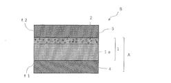
- the optical film A with an adhesive layer of the present invention has an optical film 4 and an adhesive layer 1 provided on one side or both sides of the optical film 4.
- the pressure-sensitive adhesive layer 1 is provided on either one side or both sides of the optical film 4.
- the 1st surface f1 side of the said adhesive layer 1 is provided in the said optical film 4.
- FIG. 5 shows a case where the support 3 b is provided on the second surface f ⁇ b> 2 of the pressure-sensitive adhesive layer 1.
- optical film As an optical film, what is used for formation of image display apparatuses, such as a liquid crystal display device, is used, for example, The kind in particular is not restrict
- a polarizing film is mentioned as an optical film.
- a polarizing film having a transparent protective film on one or both sides of a polarizer is generally used.
- polarizing film examples include those having a transparent protective film on at least one surface of a polarizer.
- the polarizer is not particularly limited, and various types can be used.
- polarizers include dichroic iodine and dichroic dyes on hydrophilic polymer films such as polyvinyl alcohol films, partially formalized polyvinyl alcohol films, and ethylene / vinyl acetate copolymer partially saponified films.
- hydrophilic polymer films such as polyvinyl alcohol films, partially formalized polyvinyl alcohol films, and ethylene / vinyl acetate copolymer partially saponified films.
- examples thereof include polyene-based oriented films such as those obtained by adsorbing substances and uniaxially stretched, polyvinyl alcohol dehydrated products and polyvinyl chloride dehydrochlorinated products.
- a polarizer composed of a polyvinyl alcohol film and a dichroic substance such as iodine is preferable.
- the thickness of these polarizers is not particularly limited, but is generally about 5 to 80 ⁇ m.
- a polarizer obtained by dyeing a polyvinyl alcohol film with iodine and uniaxially stretching can be prepared, for example, by dyeing a polyvinyl alcohol film in an iodine aqueous solution and stretching it 3 to 7 times the original length. it can. If necessary, it can be immersed in an aqueous solution of potassium iodide or the like which may contain boric acid, zinc sulfate, zinc chloride or the like. Further, if necessary, the polyvinyl alcohol film may be immersed in water and washed before dyeing.
- Stretching may be performed after dyeing with iodine, may be performed while dyeing, or may be dyed with iodine after stretching.
- the film can be stretched even in an aqueous solution of boric acid or potassium iodide or in a water bath.
- a thin polarizer having a thickness of 10 ⁇ m or less can also be used.
- the thickness is preferably 1 to 7 ⁇ m.
- Such a thin polarizer is preferable in that the thickness unevenness is small, the visibility is excellent, the dimensional change is small, the durability is excellent, and the thickness of the polarizing film can be reduced.
- a thin polarizing film described in Japanese Patent No. 073563 can be given.
- These thin polarizing films can be obtained by a production method including a step of stretching and dyeing a polyvinyl alcohol-based resin (hereinafter also referred to as PVA-based resin) layer and a stretching resin substrate in the state of a laminate.
- PVA-based resin polyvinyl alcohol-based resin
- thermoplastic resin excellent in transparency, mechanical strength, thermal stability, moisture barrier property, isotropy and the like is used.
- thermoplastic resins include cellulose resins such as triacetyl cellulose, polyester resins, polyethersulfone resins, polysulfone resins, polycarbonate resins, polyamide resins, polyimide resins, polyolefin resins, (meth) acrylic resins, cyclic Examples thereof include polyolefin resins (norbornene resins), polyarylate resins, polystyrene resins, polyvinyl alcohol resins, and mixtures thereof.
- a transparent protective film is bonded to one side of the polarizer by an adhesive layer.
- thermosetting resin such as a system or an ultraviolet curable resin
- a thermosetting resin such as a system or an ultraviolet curable resin
- the additive include an ultraviolet absorber, an antioxidant, a lubricant, a plasticizer, a mold release agent, a coloring inhibitor, a flame retardant, a nucleating agent, an antistatic agent, a pigment, and a coloring agent.
- the content of the thermoplastic resin in the transparent protective film is preferably 50 to 100% by weight, more preferably 50 to 99% by weight, still more preferably 60 to 98% by weight, and particularly preferably 70 to 97% by weight. .
- content of the said thermoplastic resin in a transparent protective film is 50 weight% or less, there exists a possibility that the high transparency etc. which a thermoplastic resin originally has cannot fully be expressed.
- the thickness of the transparent protective film can be appropriately determined, but is generally about 1 to 500 ⁇ m from the viewpoints of workability such as strength and handleability, and thin film properties.
- a functional layer such as a hard coat layer, an antireflection layer, or an antisticking layer can be formed on the surface of the transparent protective film to which the polarizer is not adhered, and a treatment for diffusion or antiglare is performed. It may be.
- the adhesive used for laminating the polarizer and the transparent protective film is not particularly limited as long as it is optically transparent, and water-based, solvent-based, hot-melt-based, radical curable, and cationic curable types are used. However, water-based adhesives or radical curable adhesives are suitable.
- an optical film it is used for forming a liquid crystal display device such as a reflection plate, an anti-transmission plate, a retardation film (including wavelength plates such as 1/2 and 1/4), a visual compensation film, and a brightness enhancement film. And an optical layer that may be formed. These can be used alone as an optical film, or can be laminated on the polarizing film for practical use to use one layer or two or more layers.
- a retardation film can also be used as the transparent protective film.
- the retardation film a film obtained by stretching / shrinking a polymer film or a film obtained by aligning and fixing a liquid crystal material can be appropriately used depending on the purpose.
- An optical film obtained by laminating the optical layer on a polarizing film can be formed by a method of laminating separately sequentially in the manufacturing process of a liquid crystal display device or the like.
- an appropriate adhesive means such as an adhesive layer can be used for the lamination.
- their optical axes can be set at an appropriate arrangement angle in accordance with a target retardation characteristic or the like.
- the optical laminate B of the present invention includes an optical film A with an adhesive layer and an optical member 5 having a low refractive index bonded to the adhesive layer 1 of the optical film A with an adhesive layer.
- the optical member 5 is provided on the second surface f2 side of the pressure-sensitive adhesive layer 1.
- the optical layered body B shown in FIG. 6 has the optical member 5 attached to the pressure-sensitive adhesive layer 1 after peeling the support 3b (for example, a release film) from the optical film A with the pressure-sensitive adhesive layer shown in FIG. The case of being combined is illustrated.
- the optical member 5 include an antireflection film, a light diffusion film, a prism film, a light guide film, a lens film, a Fresnel lens, a lenticular lens, and a microlens film.
- the optical film or optical laminate with an adhesive layer of the present invention can be preferably used for forming various image display devices such as liquid crystal display devices.
- the liquid crystal display device can be formed according to the conventional method. That is, a liquid crystal display device is generally formed by assembling a drive circuit by appropriately assembling components such as a display panel such as a liquid crystal cell and an optical film with an adhesive layer, or an optical laminate and an illumination system as required.
- a liquid crystal display device is generally formed by assembling a drive circuit by appropriately assembling components such as a display panel such as a liquid crystal cell and an optical film with an adhesive layer, or an optical laminate and an illumination system as required.
- the optical film with the pressure-sensitive adhesive layer or the optical laminate according to the present invention is used, and it can conform to the conventional one.
- an arbitrary type such as an arbitrary type such as a TN type, STN type, ⁇ type, VA type, or IPS type can be used.
- Appropriate liquid crystal display devices such as a liquid crystal display device in which an optical film with an adhesive layer or an optical laminate is disposed on one or both sides of a display panel such as a liquid crystal cell, or a backlight or reflector used in an illumination system are formed. can do.
- the optical film or optical laminated body with an adhesive layer by this invention can be installed in the one side or both sides of display panels, such as a liquid crystal cell.
- optical films are provided on both sides, they may be the same or different.
- a liquid crystal display device for example, a single layer or a suitable layer of suitable components such as a diffusion layer, an antiglare layer, an antireflection film, a protective plate, a prism array, a lens array sheet, a light diffusion sheet, and a backlight, Two or more layers can be arranged.
- suitable components such as a diffusion layer, an antiglare layer, an antireflection film, a protective plate, a prism array, a lens array sheet, a light diffusion sheet, and a backlight.
- Comparative Example 1 (Preparation of pressure-sensitive adhesive composition (A)) 2-ethylhexyl acrylate (2EHA) 41 parts by weight, isostearyl acrylate (ISTA) 41 parts by weight, N-vinyl-2-pyrrolidone (NVP) 14 parts by weight, N-2-hydroxybutyl acrylate (4HBA) 4 parts by weight, 2
- a seed photopolymerization initiator (trade name: Irgacure 184, manufactured by BASF) 0.035 parts by weight and a photopolymerization initiator (trade name: Irgacure 651, manufactured by BASF) 0.035 parts by weight are charged into a four-necked flask. A monomer mixture was prepared.
- this monomer mixture was partially photopolymerized by exposing it to ultraviolet rays under a nitrogen atmosphere to obtain a partially polymerized product (acrylic polymer syrup) having a polymerization rate of about 10% by weight.
- a partially polymerized product (acrylic polymer syrup) having a polymerization rate of about 10% by weight.
- TMPTA trimethylolpropane triacrylate
- silane coupling agent trade name: KBM-403, manufactured by Shin-Etsu Chemical Co., Ltd.
- the pressure-sensitive adhesive composition (A) was applied on the release-treated surface of the release film so that the thickness after forming the pressure-sensitive adhesive layer was 100 ⁇ m to form a coating layer.
- another release film was coated on the surface of the coating layer so that the release treatment surface was on the coating layer side.
- UV irradiation is performed under the conditions of illuminance: 6.5 mW / cm 2 , light quantity: 2000 mJ / cm 2 , peak wavelength: 350 nm, and the coating layer is photocured to form the pressure-sensitive adhesive layer (A).
- a pressure-sensitive adhesive sheet (base-less type, pressure-sensitive adhesive layer thickness: 100 ⁇ m) in which release films were provided on both surfaces of the layer (A) was produced.
- the refractive index (n D ) of D line measured by an Abbe refractometer of the pressure-sensitive adhesive layer (A) in an environment of 23 ° C. was 1.48, and the gel fraction was 67%.
- Comparative Example 2 (Preparation of pressure-sensitive adhesive composition (B)) Photopolymerization started on a monomer mixture composed of 76 parts by weight of 2-ethylhexyl acrylate (2EHA), 18 parts by weight of N-vinyl-2-pyrrolidone (NVP), and 16 parts by weight of 2-hydroxyethyl acrylate (HEA).
- EHA 2-ethylhexyl acrylate
- NDP N-vinyl-2-pyrrolidone
- HSA 2-hydroxyethyl acrylate
- 1-hydroxycyclohexyl phenyl ketone (trade name: Irgacure 184, having an absorption band at a wavelength of 200 to 370 nm, manufactured by BASF) 0.050 part by weight
- 2,2-dimethoxy-1,2-diphenylethane-1 -ON (trade name: Irgacure 651, having an absorption band at a wavelength of 200 to 380 nm, manufactured by BASF) 0.050 parts by weight
- viscosity measurement conditions: BH viscometer No.
- the pressure-sensitive adhesive composition (B) was applied onto the release-treated surface of the release film so that the thickness after forming the pressure-sensitive adhesive layer was 150 ⁇ m to form a coating layer.
- another release film was coated on the surface of the coating layer so that the release treatment surface was on the coating layer side.
- UV irradiation was performed under the conditions of illuminance: 6.5 mW / cm 2 , light quantity: 2000 mJ / cm 2 , peak wavelength: 350 nm, and the coating layer was photocured to form the pressure-sensitive adhesive layer (B).
- a pressure-sensitive adhesive sheet (baseless type, pressure-sensitive adhesive layer thickness: 150 ⁇ m) having release films provided on both sides of the agent layer (B) was produced.
- the refractive index (n D ) of D line measured by an Abbe refractometer of the pressure-sensitive adhesive layer (B) in an environment of 23 ° C. was 1.49, and the gel fraction was 88%.
- a pressure-sensitive adhesive composition (C: solution) was prepared by adding 0.1 part by weight of a silane coupling agent (trade name: KBM-403, manufactured by Shin-Etsu Chemical Co., Ltd.).
- the pressure-sensitive adhesive composition (C: solution) was applied on the release-treated surface of the release film so that the thickness after drying was 23 ⁇ m, and then dried at 100 ° C. for 3 minutes to form a solvent. Was removed to obtain a pressure-sensitive adhesive layer (C). Then, the crosslinking process was performed by heating at 50 degreeC for 48 hours. The exposed surface of the obtained pressure-sensitive adhesive layer (C) is covered with another release film so that the release-treated surface is on the exposed surface side, and the release film is formed on both surfaces of the pressure-sensitive adhesive layer (C).
- a pressure-sensitive adhesive sheet (baseless type, pressure-sensitive adhesive layer thickness: 23 ⁇ m) was prepared.
- the refractive index (n D ) of D line measured by an Abbe refractometer of the pressure-sensitive adhesive layer (C) in an environment of 23 ° C. was 1.47, and the gel fraction was 82%.
- Comparative Example 4 (Preparation of pressure-sensitive adhesive composition (D))
- a separable flask equipped with a thermometer, a stirrer, a reflux condenser, and a nitrogen gas introduction tube 99 parts by weight of butyl acrylate (BA) as a monomer component, 1 part by weight of 4 hydroxybutyl acrylate (4HBA), and azo as a polymerization initiator
- BA butyl acrylate
- 4HBA 4 hydroxybutyl acrylate
- azo a polymerization initiator
- nitrogen substitution was performed for about 1 hour while flowing nitrogen gas and stirring. Thereafter, the flask was heated to 60 ° C.
- the pressure-sensitive adhesive composition (D: solution) was applied onto the release-treated surface of the release film so that the thickness after drying was 20 ⁇ m, and then dried at 120 ° C. for 3 minutes to remove the solvent. Thus, an adhesive layer (D) was obtained. Then, the crosslinking process was performed by heating at 50 degreeC for 48 hours. The exposed surface of the obtained pressure-sensitive adhesive layer (D) is coated with another release film so that the release-treated surface is on the exposed surface side, and the release film is formed on both surfaces of the pressure-sensitive adhesive layer (D).
- a pressure-sensitive adhesive sheet baseless type, pressure-sensitive adhesive layer thickness: 23 ⁇ m
- the refractive index (n D ) of D line measured by an Abbe refractometer of the pressure-sensitive adhesive layer (D) in an environment of 23 ° C. was 1.47, and the gel fraction was 75%.
- Example 1 Preparation of dispersion containing low refractive index particles
- hollow nanosilica particles hollow particles, refractive index: 1.24, average primary particle size: 75 nm, trade name: Thruria 5320, manufactured by JGC Catalysts & Chemicals Co., Ltd.
- Examples 2-8 Example 1 except that the type of the pressure-sensitive adhesive layer and the type of dispersion (the type of low refractive index particles, the average particle diameter thereof, the type of dispersion medium, and the particle concentration) were changed as shown in Table 1.
- a pressure-sensitive adhesive sheet having a pressure-sensitive adhesive layer with an adjusted refractive index was produced.
- the target thickness of the refractive index adjustment region after drying is about 150 to 300 nm or more, bar coater RDS No. 5 is used, and the target thickness of the refractive index adjustment region after drying is 20 to 150 nm. In the case of grade, bar coater RDS No. 3 was used.
- Table 1 shows the results of the following evaluations performed on the pressure-sensitive adhesive layers (pressure-sensitive adhesive sheets) obtained in Examples and Comparative Examples.
- the average surface refractive index of the pressure-sensitive adhesive layer (refractive index adjusting region side: second surface) obtained in the examples was measured using a spectroscopic ellipsometer (EC-400, manufactured by JA Woolam) at sodium D line (589 nm). The refractive index was measured. From the pressure-sensitive adhesive sheets obtained in Examples and Comparative Examples, the release films on both sides were peeled off, and the dispersion liquid was applied in a state where the blackboard was bonded to the surface where the dispersion liquid was not applied (first surface). The average refractive index of the surface (second surface) was measured.
- the average refractive index of the pressure-sensitive adhesive layer surface was measured in a state where both release sheets were peeled off and a blackboard was bonded to one surface.
- the pressure-sensitive adhesive layer of the pressure-sensitive adhesive sheet of the comparative example has the same refractive index on both sides.
- ⁇ Measurement of thickness of refractive index adjustment region> The cross section in the depth direction of the pressure-sensitive adhesive layer was adjusted, and TEM observation was performed. The thickness of the refractive index adjustment region was measured from the obtained TEM image (direct magnification: 3000 to 30000 times). The thickness of the refractive index adjustment region is an average value of the unevenness of the interface between the region where the particles are dispersed and the region where the particle is not dispersed in the pressure-sensitive adhesive layer.
- the binarized image processing was performed with image processing software (ImageJ), and the thickness of the region where 90% (area) of the particles existed was determined.
- the second release film (the second surface side of the pressure-sensitive adhesive layer) was peeled off from the pressure-sensitive adhesive sheet obtained in the examples, and a slide glass (trade name: white polishing No. 1, thickness: 0.8 to 1) 0.0 mm, total light transmittance: 92%, haze: 0.2%, manufactured by Matsunami Glass Industry Co., Ltd.). Furthermore, the other 1st release film was peeled and the test piece which has a layer structure of an adhesive layer (refractive index adjustment area
- one release film is peeled off and bonded to the same slide glass as described above, and the other release film is peeled off to form a pressure-sensitive adhesive layer / slide glass layer structure.
- a test piece was prepared. The total light transmittance and haze value in the visible light region of the test piece were measured using a haze meter (device name: HM-150, manufactured by Murakami Color Research Laboratory).
- ⁇ Adhesiveness> A sheet piece having a length of 100 mm and a width of 20 mm was cut out from the pressure-sensitive adhesive sheets obtained in Examples and Comparative Examples. Next, from the sheet piece obtained from the pressure-sensitive adhesive sheet of the example, the first release film (side on which the dispersion liquid was not applied in the pressure-sensitive adhesive layer) was peeled off, and then the PET film (product) Name: Lumirror S-10, thickness: 25 ⁇ m, manufactured by Toray Industries, Inc.) was attached (backed).
- the second release film is peeled off, and is bonded to a glass plate as a test plate (trade name: soda lime glass # 0050, manufactured by Matsunami Glass Industry Co., Ltd.) under a 2 kg roller, one reciprocating pressure condition.
- a sample composed of a test plate / adhesive layer (first side is PET side) / PET film was prepared.
- the sheet piece obtained from the pressure-sensitive adhesive sheet of the comparative example was peeled off one release film, and then, on the pressure-sensitive adhesive layer surface, the same PET film was peeled off, and then the other release film was peeled off.
- a sample was prepared using the same test plate.
- the obtained sample was autoclaved (50 ° C., 0.5 MPa, 15 minutes), and then 23 ° C., 50% R.D. H. And allowed to cool for 30 minutes. After allowing to cool, a tensile tester (device name: Autograph AG-IS, manufactured by Shimadzu Corporation) was used, and the temperature was 23 ° C. and 50% R.D. according to JIS Z0237. H. Under the above conditions, the pressure-sensitive adhesive sheet (pressure-sensitive adhesive layer / PET film) was peeled off from the test plate under the conditions of a tensile speed of 300 mm / min and a peeling angle of 180 °, and the 180 ° peel-off adhesive strength (N / 20 mm) was measured.
- a tensile tester device name: Autograph AG-IS, manufactured by Shimadzu Corporation
- the surface (second surface) on which the dispersion liquid of the pressure-sensitive adhesive layer obtained in the examples was applied was used as a reflectance measurement surface.
- the first release film (the side where the dispersion liquid was not applied in the pressure-sensitive adhesive layer) was peeled off from the pressure-sensitive adhesive sheet obtained in the example, and a black acrylic plate (trade name “CLAREX”, manufactured by Nitto Resin Co., Ltd.) was attached.
- the second release film (the side on which the dispersion liquid was applied in the pressure-sensitive adhesive layer) was peeled off, and the peeled surface was used as a sample for measuring surface reflectance.
- the surface of the pressure-sensitive adhesive layer had a refractive index of 1.36 on the triacetyl cellulose film.
- the laminated film on which the low refractive index layer was formed was bonded to the low refractive layer side so that the low refractive index adjustment region of the pressure-sensitive adhesive layer was in contact with the low refractive index layer on the laminated film.
- the first release film was peeled off, and a slide glass (trade name: white polishing No.
- the internal reflection suppression rate was calculated based on the following equation by measuring the transmittance of the test piece prepared above.
- “transmittance without particles (%)” is the reflectance of the test piece of the comparative example. That is, the internal reflection suppressing effect (transmittance improving effect) is an index indicating how much the internal reflectance can be reduced by having the refractive index adjustment layer.
- Internal reflection suppression rate (%) "Transmittance (%)"-"Transmittance without particles (%)"
- Adhesive layer 1a Base of the entire adhesive layer (matrix) 2 ....
Landscapes
- Chemical & Material Sciences (AREA)
- Organic Chemistry (AREA)
- Physics & Mathematics (AREA)
- Inorganic Chemistry (AREA)
- Optics & Photonics (AREA)
- General Physics & Mathematics (AREA)
- Polymers & Plastics (AREA)
- Health & Medical Sciences (AREA)
- Medicinal Chemistry (AREA)
- Chemical Kinetics & Catalysis (AREA)
- Adhesives Or Adhesive Processes (AREA)
- Adhesive Tapes (AREA)
- Polarising Elements (AREA)
- Surface Treatment Of Optical Elements (AREA)
- Laminated Bodies (AREA)
- Optical Elements Other Than Lenses (AREA)
- Liquid Crystal (AREA)
Priority Applications (5)
| Application Number | Priority Date | Filing Date | Title |
|---|---|---|---|
| CN201980030221.4A CN112074580A (zh) | 2018-05-11 | 2019-04-10 | 粘合剂层、其制造方法、粘合片、带粘合剂层的光学膜和图像显示装置 |
| CN202310382624.3A CN116515457A (zh) | 2018-05-11 | 2019-04-10 | 粘合剂层、其制造方法、粘合片、带粘合剂层的光学膜和图像显示装置 |
| SG11202011147XA SG11202011147XA (en) | 2018-05-11 | 2019-04-10 | Pressure-sensitive adhesive layer, method for producing same, pressure-sensitive adhesive sheet, pressure-sensitive adhesive layer-attached optical film, and image display device |
| KR1020247036303A KR20240161219A (ko) | 2018-05-11 | 2019-04-10 | 점착제층, 그 제조 방법, 점착 시트, 점착제층을 갖춘 광학 필름, 및 화상 표시 장치 |
| KR1020207033460A KR20210009322A (ko) | 2018-05-11 | 2019-04-10 | 점착제층, 그 제조 방법, 점착 시트, 점착제층을 갖춘 광학 필름, 및 화상 표시 장치 |
Applications Claiming Priority (2)
| Application Number | Priority Date | Filing Date | Title |
|---|---|---|---|
| JP2018092443A JP7685816B2 (ja) | 2018-05-11 | 2018-05-11 | 粘着剤層、その製造方法、粘着シート、粘着剤層付光学フィルムおよび画像表示装置 |
| JP2018-092443 | 2018-05-11 |
Publications (1)
| Publication Number | Publication Date |
|---|---|
| WO2019216096A1 true WO2019216096A1 (ja) | 2019-11-14 |
Family
ID=68467931
Family Applications (1)
| Application Number | Title | Priority Date | Filing Date |
|---|---|---|---|
| PCT/JP2019/015629 Ceased WO2019216096A1 (ja) | 2018-05-11 | 2019-04-10 | 粘着剤層、その製造方法、粘着シート、粘着剤層付光学フィルムおよび画像表示装置 |
Country Status (5)
| Country | Link |
|---|---|
| JP (2) | JP7685816B2 (https=) |
| KR (2) | KR20210009322A (https=) |
| CN (2) | CN112074580A (https=) |
| SG (1) | SG11202011147XA (https=) |
| WO (1) | WO2019216096A1 (https=) |
Cited By (1)
| Publication number | Priority date | Publication date | Assignee | Title |
|---|---|---|---|---|
| KR20220071019A (ko) * | 2020-11-23 | 2022-05-31 | 김중석 | 고점착, 고두께의 고기능성 실리콘 점착제 및 이를 이용한 필름 |
Families Citing this family (5)
| Publication number | Priority date | Publication date | Assignee | Title |
|---|---|---|---|---|
| JP7685816B2 (ja) * | 2018-05-11 | 2025-05-30 | 日東電工株式会社 | 粘着剤層、その製造方法、粘着シート、粘着剤層付光学フィルムおよび画像表示装置 |
| JP7052786B2 (ja) | 2018-12-14 | 2022-04-12 | 株式会社デンソー | 表示制御装置および表示制御プログラム |
| JP7523224B2 (ja) | 2020-02-07 | 2024-07-26 | 日東電工株式会社 | 粘着シート |
| KR102486600B1 (ko) * | 2020-02-20 | 2023-01-09 | 삼성에스디아이 주식회사 | 점착 필름, 이를 포함하는 비산 방지 필름 및 이를 포함하는 광학표시장치 |
| WO2024083344A1 (en) * | 2022-10-21 | 2024-04-25 | Huawei Technologies Co., Ltd. | Flexible display stack and apparatus comprising such display stack |
Citations (10)
| Publication number | Priority date | Publication date | Assignee | Title |
|---|---|---|---|---|
| WO2002067044A1 (en) * | 2001-02-19 | 2002-08-29 | Matsushita Electric Industrial Co., Ltd. | Liquid crystal display employing plastic substrate |
| JP2011037978A (ja) * | 2009-08-10 | 2011-02-24 | Sekisui Chem Co Ltd | 低屈折率接着剤 |
| KR20120049650A (ko) * | 2010-11-09 | 2012-05-17 | 주식회사 엘지화학 | 백라이트 유닛 |
| WO2015060177A1 (ja) * | 2013-10-22 | 2015-04-30 | 三菱樹脂株式会社 | 透明粘着材及びフロントライト型画像表示装置 |
| WO2015108159A1 (ja) * | 2014-01-17 | 2015-07-23 | 日東電工株式会社 | 粘着剤層を有する光学部材積層体及びその製造方法 |
| JP2016160284A (ja) * | 2015-02-26 | 2016-09-05 | 旭化成株式会社 | 光硬化性樹脂組成物及びその製造方法 |
| JP2017024266A (ja) * | 2015-07-22 | 2017-02-02 | 日東電工株式会社 | 積層体及びその製造方法 |
| JP2017043678A (ja) * | 2015-08-25 | 2017-03-02 | 日東電工株式会社 | 光学部材用粘着剤層、粘着剤層付光学部材、及び画像表示装置 |
| JP2017064954A (ja) * | 2015-09-28 | 2017-04-06 | 日東電工株式会社 | 積層フィルムの製造方法および画像表示装置の製造方法 |
| JP2017171819A (ja) * | 2016-03-25 | 2017-09-28 | 日立マクセル株式会社 | 粘着性組成物、粘着性部材及びその製造方法、粘着性シート及びその製造方法、並びに粘着性部材を含む電子機器 |
Family Cites Families (6)
| Publication number | Priority date | Publication date | Assignee | Title |
|---|---|---|---|---|
| JP3684587B2 (ja) * | 1994-02-04 | 2005-08-17 | 住友化学株式会社 | 光拡散性メタクリル系樹脂板 |
| JP2009132803A (ja) | 2007-11-30 | 2009-06-18 | Nitto Denko Corp | リワーク性粘着部材 |
| WO2013114945A1 (ja) * | 2012-01-31 | 2013-08-08 | 東レフィルム加工株式会社 | 透明導電性フィルム、タッチパネルおよび表示装置 |
| JP6285127B2 (ja) | 2012-09-13 | 2018-02-28 | 日東電工株式会社 | 光拡散粘着剤ならびに該光拡散粘着剤を用いた偏光板および光学部材 |
| WO2016152787A1 (ja) * | 2015-03-24 | 2016-09-29 | デクセリアルズ株式会社 | 両面粘着テープ、及びその製造方法 |
| JP7685816B2 (ja) * | 2018-05-11 | 2025-05-30 | 日東電工株式会社 | 粘着剤層、その製造方法、粘着シート、粘着剤層付光学フィルムおよび画像表示装置 |
-
2018
- 2018-05-11 JP JP2018092443A patent/JP7685816B2/ja active Active
-
2019
- 2019-04-10 CN CN201980030221.4A patent/CN112074580A/zh active Pending
- 2019-04-10 SG SG11202011147XA patent/SG11202011147XA/en unknown
- 2019-04-10 KR KR1020207033460A patent/KR20210009322A/ko not_active Ceased
- 2019-04-10 CN CN202310382624.3A patent/CN116515457A/zh active Pending
- 2019-04-10 WO PCT/JP2019/015629 patent/WO2019216096A1/ja not_active Ceased
- 2019-04-10 KR KR1020247036303A patent/KR20240161219A/ko active Pending
-
2023
- 2023-02-27 JP JP2023028490A patent/JP7696381B2/ja active Active
Patent Citations (10)
| Publication number | Priority date | Publication date | Assignee | Title |
|---|---|---|---|---|
| WO2002067044A1 (en) * | 2001-02-19 | 2002-08-29 | Matsushita Electric Industrial Co., Ltd. | Liquid crystal display employing plastic substrate |
| JP2011037978A (ja) * | 2009-08-10 | 2011-02-24 | Sekisui Chem Co Ltd | 低屈折率接着剤 |
| KR20120049650A (ko) * | 2010-11-09 | 2012-05-17 | 주식회사 엘지화학 | 백라이트 유닛 |
| WO2015060177A1 (ja) * | 2013-10-22 | 2015-04-30 | 三菱樹脂株式会社 | 透明粘着材及びフロントライト型画像表示装置 |
| WO2015108159A1 (ja) * | 2014-01-17 | 2015-07-23 | 日東電工株式会社 | 粘着剤層を有する光学部材積層体及びその製造方法 |
| JP2016160284A (ja) * | 2015-02-26 | 2016-09-05 | 旭化成株式会社 | 光硬化性樹脂組成物及びその製造方法 |
| JP2017024266A (ja) * | 2015-07-22 | 2017-02-02 | 日東電工株式会社 | 積層体及びその製造方法 |
| JP2017043678A (ja) * | 2015-08-25 | 2017-03-02 | 日東電工株式会社 | 光学部材用粘着剤層、粘着剤層付光学部材、及び画像表示装置 |
| JP2017064954A (ja) * | 2015-09-28 | 2017-04-06 | 日東電工株式会社 | 積層フィルムの製造方法および画像表示装置の製造方法 |
| JP2017171819A (ja) * | 2016-03-25 | 2017-09-28 | 日立マクセル株式会社 | 粘着性組成物、粘着性部材及びその製造方法、粘着性シート及びその製造方法、並びに粘着性部材を含む電子機器 |
Cited By (2)
| Publication number | Priority date | Publication date | Assignee | Title |
|---|---|---|---|---|
| KR20220071019A (ko) * | 2020-11-23 | 2022-05-31 | 김중석 | 고점착, 고두께의 고기능성 실리콘 점착제 및 이를 이용한 필름 |
| KR102459692B1 (ko) * | 2020-11-23 | 2022-10-26 | 김중석 | 고점착, 고두께의 고기능성 실리콘 점착제 및 이를 이용한 필름 |
Also Published As
| Publication number | Publication date |
|---|---|
| TW202413578A (zh) | 2024-04-01 |
| SG11202011147XA (en) | 2020-12-30 |
| KR20210009322A (ko) | 2021-01-26 |
| KR20240161219A (ko) | 2024-11-12 |
| JP7685816B2 (ja) | 2025-05-30 |
| JP2023059986A (ja) | 2023-04-27 |
| CN112074580A (zh) | 2020-12-11 |
| CN116515457A (zh) | 2023-08-01 |
| TW201946995A (zh) | 2019-12-16 |
| JP7696381B2 (ja) | 2025-06-20 |
| JP2019196468A (ja) | 2019-11-14 |
Similar Documents
| Publication | Publication Date | Title |
|---|---|---|
| JP7696381B2 (ja) | 粘着剤層、その製造方法、粘着シート、粘着剤層付光学フィルムおよび画像表示装置 | |
| TWI727494B (zh) | 雙面附黏著劑之光學膜、及使用其之圖像顯示裝置之製造方法、以及雙面附黏著劑之光學膜之捲曲抑制方法 | |
| CN103764777B (zh) | 压敏粘合剂 | |
| TWI813901B (zh) | 附黏著劑層之偏光薄膜及影像顯示裝置 | |
| CN113773757B (zh) | 丙烯酸类粘合剂组合物、粘合剂层及其制造方法、带粘合剂层的偏振膜及图像显示装置 | |
| CN108230900A (zh) | 图像显示装置 | |
| CN108431959A (zh) | 有机el显示装置用粘合剂组合物、有机el显示装置用粘合剂层、带有有机el显示装置用粘合剂层的偏振膜和有机el显示装置 | |
| TWI746487B (zh) | 附黏著劑層之偏光薄膜及影像顯示裝置 | |
| KR102755811B1 (ko) | 액정층 적층체 | |
| CN110643287A (zh) | 粘着片及光学层叠体 | |
| KR101587351B1 (ko) | 광산란 점착 필름, 편광판 및 액정 표시 장치 | |
| WO2024070789A1 (ja) | 粘着剤および粘着シート | |
| JP2004240087A (ja) | 積層偏光フィルム | |
| TWI896625B (zh) | 雙面附黏著劑之光學膜、及圖像顯示裝置 | |
| KR20190015236A (ko) | 점착제층을 갖는 편광 필름, 및 화상 표시 장치 | |
| TW202421750A (zh) | 黏著劑及黏著片材 | |
| TWI717357B (zh) | 紫外線硬化型丙烯酸系黏著劑組成物、紫外線硬化型丙烯酸系黏著劑層、附有黏著劑層之偏光薄膜、紫外線硬化型丙烯酸系黏著劑層之製造方法、及影像顯示裝置 | |
| CN110268292A (zh) | 带光学功能层的偏振膜及液晶显示装置 | |
| TWI917309B (zh) | 黏著劑層、其製造方法、黏著片、附黏著劑層之光學膜及圖像顯示裝置 | |
| TWI917827B (zh) | 黏著劑層、其製造方法、黏著片、附黏著劑層之光學膜及圖像顯示裝置 | |
| JP7755936B2 (ja) | 粘着シート、粘着剤層付き光学フィルム、および光学積層体 | |
| TWI764605B (zh) | 光學黏著劑、光學黏著層及其形成方法、以及光學層合物 | |
| JP2024146806A (ja) | 粘着シート用光硬化性組成物、粘着シート、光学積層体及び画像表示装置 | |
| TW202026377A (zh) | 紫外線硬化型丙烯酸系黏著劑組成物、紫外線硬化型丙烯酸系黏著劑層、附有黏著劑層之偏光薄膜、紫外線硬化型丙烯酸系黏著劑層之製造方法、及影像顯示裝置 | |
| JP2025155996A (ja) | 粘着シートおよび光学積層体 |
Legal Events
| Date | Code | Title | Description |
|---|---|---|---|
| 121 | Ep: the epo has been informed by wipo that ep was designated in this application |
Ref document number: 19800650 Country of ref document: EP Kind code of ref document: A1 |
|
| NENP | Non-entry into the national phase |
Ref country code: DE |
|
| 122 | Ep: pct application non-entry in european phase |
Ref document number: 19800650 Country of ref document: EP Kind code of ref document: A1 |