WO2019208320A1 - 車両衝突推定装置 - Google Patents
車両衝突推定装置 Download PDFInfo
- Publication number
- WO2019208320A1 WO2019208320A1 PCT/JP2019/016263 JP2019016263W WO2019208320A1 WO 2019208320 A1 WO2019208320 A1 WO 2019208320A1 JP 2019016263 W JP2019016263 W JP 2019016263W WO 2019208320 A1 WO2019208320 A1 WO 2019208320A1
- Authority
- WO
- WIPO (PCT)
- Prior art keywords
- vehicle
- collision
- collision estimation
- preceding vehicle
- condition
- Prior art date
- Legal status (The legal status is an assumption and is not a legal conclusion. Google has not performed a legal analysis and makes no representation as to the accuracy of the status listed.)
- Ceased
Links
Images


Classifications
-
- B—PERFORMING OPERATIONS; TRANSPORTING
- B60—VEHICLES IN GENERAL
- B60W—CONJOINT CONTROL OF VEHICLE SUB-UNITS OF DIFFERENT TYPE OR DIFFERENT FUNCTION; CONTROL SYSTEMS SPECIALLY ADAPTED FOR HYBRID VEHICLES; ROAD VEHICLE DRIVE CONTROL SYSTEMS FOR PURPOSES NOT RELATED TO THE CONTROL OF A PARTICULAR SUB-UNIT
- B60W30/00—Purposes of road vehicle drive control systems not related to the control of a particular sub-unit, e.g. of systems using conjoint control of vehicle sub-units
- B60W30/08—Active safety systems predicting or avoiding probable or impending collision or attempting to minimise its consequences
- B60W30/095—Predicting travel path or likelihood of collision
- B60W30/0956—Predicting travel path or likelihood of collision the prediction being responsive to traffic or environmental parameters
-
- B—PERFORMING OPERATIONS; TRANSPORTING
- B60—VEHICLES IN GENERAL
- B60W—CONJOINT CONTROL OF VEHICLE SUB-UNITS OF DIFFERENT TYPE OR DIFFERENT FUNCTION; CONTROL SYSTEMS SPECIALLY ADAPTED FOR HYBRID VEHICLES; ROAD VEHICLE DRIVE CONTROL SYSTEMS FOR PURPOSES NOT RELATED TO THE CONTROL OF A PARTICULAR SUB-UNIT
- B60W30/00—Purposes of road vehicle drive control systems not related to the control of a particular sub-unit, e.g. of systems using conjoint control of vehicle sub-units
- B60W30/08—Active safety systems predicting or avoiding probable or impending collision or attempting to minimise its consequences
- B60W30/09—Taking automatic action to avoid collision, e.g. braking and steering
-
- B—PERFORMING OPERATIONS; TRANSPORTING
- B60—VEHICLES IN GENERAL
- B60W—CONJOINT CONTROL OF VEHICLE SUB-UNITS OF DIFFERENT TYPE OR DIFFERENT FUNCTION; CONTROL SYSTEMS SPECIALLY ADAPTED FOR HYBRID VEHICLES; ROAD VEHICLE DRIVE CONTROL SYSTEMS FOR PURPOSES NOT RELATED TO THE CONTROL OF A PARTICULAR SUB-UNIT
- B60W50/00—Details of control systems for road vehicle drive control not related to the control of a particular sub-unit, e.g. process diagnostic or vehicle driver interfaces
- B60W50/08—Interaction between the driver and the control system
- B60W50/14—Means for informing the driver, warning the driver or prompting a driver intervention
-
- G—PHYSICS
- G08—SIGNALLING
- G08G—TRAFFIC CONTROL SYSTEMS
- G08G1/00—Traffic control systems for road vehicles
- G08G1/16—Anti-collision systems
-
- B—PERFORMING OPERATIONS; TRANSPORTING
- B60—VEHICLES IN GENERAL
- B60W—CONJOINT CONTROL OF VEHICLE SUB-UNITS OF DIFFERENT TYPE OR DIFFERENT FUNCTION; CONTROL SYSTEMS SPECIALLY ADAPTED FOR HYBRID VEHICLES; ROAD VEHICLE DRIVE CONTROL SYSTEMS FOR PURPOSES NOT RELATED TO THE CONTROL OF A PARTICULAR SUB-UNIT
- B60W2554/00—Input parameters relating to objects
- B60W2554/40—Dynamic objects, e.g. animals, windblown objects
- B60W2554/404—Characteristics
Definitions
- the present disclosure relates to a vehicle collision estimation device.
- a vehicle collision estimation device there is known a device that warns a driver when it is estimated that the vehicle may collide.
- the vehicle collision estimation apparatus described in Patent Literature 1 if another vehicle is detected at the predicted travel position of the host vehicle, it is estimated that there is a possibility of a collision.
- the conventional technology does not consider the case where the preceding vehicle makes a U-turn.
- the inventor of the present application has found that when the preceding vehicle makes a U-turn, the estimation of the possibility of a collision with the preceding vehicle may be delayed. Therefore, a technique that can reduce the possibility of a collision when the preceding vehicle makes a U-turn is desired.
- a vehicle collision estimation device is mounted on a vehicle including a peripheral sensor that detects a preceding vehicle.
- the vehicle and the preceding vehicle collide when the collision estimation region setting unit that sets a collision estimation region in front of the vehicle and the preceding vehicle exist in the collision estimation region.
- a collision estimation unit that estimates that there is a possibility that the collision estimation area setting unit determines that the preceding vehicle satisfies the predetermined U-turn condition that the U-turn is estimated to cause the preceding vehicle to make a U-turn.
- the collision estimation area is expanded as compared with the case where the U-turn condition is not satisfied.
- the collision estimation area setting unit expands the collision estimation area when the preceding vehicle satisfies the U-turn condition than when the preceding vehicle satisfies the U-turn condition. The possibility of collision when turning is reduced.
- FIG. 1 is an explanatory diagram showing an outline of the configuration of an automatic driving system.
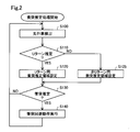
- FIG. 2 is a flowchart showing the collision estimation process.
- FIG. 3 is an explanatory diagram when the preceding vehicle satisfies the U-turn condition
- FIG. 4 is a diagram illustrating an example of a collision estimation area for a non-U-turn
- FIG. 5 is a diagram illustrating another example of the collision estimation region for non-U-turns
- FIG. 6 is a graph showing the relationship between the relative velocity and the estimated collision area length.
- FIG. 7 is a diagram showing an example of a U-turn collision estimation area.
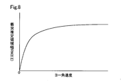
- FIG. 8 is a graph showing the relationship between the yaw angular velocity of the preceding vehicle and the estimated collision area width.
- a vehicle 100 (hereinafter also referred to as “own vehicle”) includes a vehicle collision estimation device 110, a peripheral sensor 120, a vehicle position sensor 126, a road information storage unit 130, and a notification unit 140. And an operation control EUC (Electronic Control Unit) 210, a driving force control ECU 220, a braking force control ECU 230, and a steering control ECU 240.
- the vehicle collision estimation device 110, the driving control ECU 210, the driving force control ECU 220, the braking force control ECU 230, and the steering control ECU 240 are connected via an in-vehicle network 250.
- the vehicle collision estimation device 110 includes a collision estimation region setting unit 112, a collision estimation unit 114, and a collision avoidance operation execution unit 116.
- the vehicle collision estimation device 110 is composed of a central processing unit (CPU), a microcomputer constituted by a RAM, a ROM, and the like, and the functions of these units are realized by the microcomputer executing a preinstalled program. .
- the collision estimation area setting unit 112 sets a collision estimation area.
- the “collision estimation area” is a predetermined range ahead of the host vehicle, and is used to estimate whether or not there is a possibility of a collision with a preceding vehicle. The setting of the collision estimation area will be described later.
- the collision estimation unit 114 estimates a collision with a preceding vehicle using the collision estimation region set by the collision estimation region setting unit 112 and the detection signal of the surrounding sensor 120. More specifically, the collision estimation unit 114 determines whether or not there is a preceding vehicle in the collision estimation region, and collides with the preceding vehicle when a part or all of the preceding vehicle exists in the collision estimation region. Estimate that there is a possibility.
- the collision avoidance operation executing unit 116 executes a predetermined collision avoidance operation when the collision estimation region setting unit 112 estimates that there is a possibility of collision with the preceding vehicle.
- a collision avoidance operation for example, an operation of outputting a signal to the notification unit 140 is performed in order to notify the passenger of the vehicle of the possibility of a collision with the preceding vehicle.
- the peripheral sensor 120 includes a peripheral recognition camera 122 and a peripheral object sensor 124.
- the periphery recognition camera 122 captures an image of the surroundings of the host vehicle.
- the surrounding object sensor 124 detects the situation around the host vehicle.
- Examples of the peripheral object sensor 124 include object sensors using reflected waves such as laser radar, millimeter wave radar, and ultrasonic sensor.
- the collision estimation area setting unit 112 determines the presence, position, size, distance, traveling direction, speed, and yaw angular speed of the preceding vehicle from the image captured by the peripheral recognition camera 122 and the detection result of the peripheral object sensor 124. Then, a collision margin time (TTC) until the vehicle collides with the preceding vehicle is detected.
- TTC collision margin time
- the collision estimation area setting unit 112 may detect part of the information by inter-vehicle communication with the preceding vehicle.
- the peripheral sensor 120 further detects the presence and position of the left and right lane markings of the lane in which the vehicle is traveling, the state of traffic lights, and traffic signs.
- the own vehicle position sensor 126 detects the current own vehicle position.
- Examples of the vehicle position sensor 126 include a global navigation satellite system (Global Navigation Satellite System (s) (GNSS)) and a gyro sensor.
- GNSS Global Navigation Satellite System
- the notification unit 140 is a device that notifies the driver when the possibility of a collision with a preceding vehicle is estimated.
- the notification unit 140 can be realized using, for example, a lamp such as an LED, a display device that displays characters and pictures such as a car navigation system, and an audio device such as a speaker. Moreover, you may implement
- the notification unit 140 is a speaker.
- the road information storage unit 130 stores detailed road information related to the road on which the vehicle is scheduled to travel.
- the road information stores, for example, information such as the number of lanes, lane width, center coordinates of each lane, curve curvature, stop line position, and traffic signal position. From the lane line position detected by processing the image captured by the peripheral recognition camera 122, the positioning signal of the vehicle position sensor 126, the road information read from the road information storage unit 130, and the like, including the lane that is running The own vehicle position is detected.
- the operation control ECU 210 includes a central processing unit (CPU), a microcomputer constituted by a RAM, a ROM, and the like, and realizes an automatic operation function when the microcomputer executes a program installed in advance.
- CPU central processing unit
- microcomputer constituted by a RAM, a ROM, and the like
- the driving force control ECU 220 is an electronic control device that controls an actuator that generates a driving force of a vehicle such as an engine.
- the driving force control ECU 220 controls a power source that is an engine or an electric motor according to the operation amount of the accelerator pedal.
- the driving force control ECU 220 controls the power source according to the required driving force calculated by the driving control ECU 210.
- the braking force control ECU 230 is an electronic control device that controls a brake actuator that generates a braking force of the vehicle.
- the braking force control ECU 230 controls the brake actuator according to the operation amount of the brake pedal.
- the braking force control ECU 230 controls the brake actuator according to the required braking force calculated by the driving control ECU 210.
- Steering control ECU 240 is an electronic control device that controls a motor that generates steering torque of the vehicle.
- the steering control ECU 240 controls the motor according to the operation of the steering handle to generate assist torque for the steering operation.
- the driver can operate the steering with a small amount of force, thereby realizing the steering of the vehicle.
- the steering control ECU 240 performs steering by controlling the motor according to the required steering angle calculated by the driving control ECU 210.
- the collision estimation process shown in FIG. 2 is a series of processes in which the collision estimation unit 114 estimates whether or not the host vehicle and the preceding vehicle may collide. This process is a process repeatedly executed by the vehicle collision estimation device 110 while the vehicle 100 is traveling.
- the collision estimation area setting unit 112 detects a preceding vehicle in step S100. More specifically, the position and vehicle speed of the preceding vehicle are detected from the surrounding image of the vehicle taken by the surrounding recognition camera 122 and the surrounding situation of the vehicle detected by the surrounding object sensor 124.
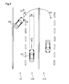
- the collision estimation area setting unit 112 estimates whether or not the preceding vehicle detected in step S100 makes a U-turn. More specifically, it is determined whether or not a predetermined U-turn condition for estimating that the preceding vehicle makes a U-turn is satisfied. Whether or not the preceding vehicle satisfies the U-turn condition can be determined using detection signals from the peripheral recognition camera 122 and the peripheral object sensor 124. As the U-turn condition, for example, any one or more of the following conditions can be adopted. Hereinafter, the U-turn condition will be described with reference to FIG. In FIG.
- the host vehicle VL1 travels in the lane Ln2
- the preceding vehicle VL2 travels in the lane Ln1 on the left side of the host vehicle VL1
- the oncoming lane Ln3 exists on the right side of the host vehicle VL1.
- the preceding vehicle VL2 makes a U-turn across the front of the host vehicle VL1.
- the preceding vehicle VL2 is in a range opposite to the opposite lane Ln3 of the host vehicle VL1 with respect to the vehicle width range W1 of the host vehicle VL1 ⁇ Condition 2> Crossing the traveling direction D1 of the host vehicle VL1 so that the traveling direction D2 of the preceding vehicle VL2 is directed to the oncoming lane Ln3 ⁇ Condition 3>
- the relative angle ⁇ of the preceding vehicle VL2 with respect to the traveling direction D1 of the host vehicle VL1 is equal to or greater than a predetermined threshold value ⁇ Condition 4>
- the increase rate of the relative angle ⁇ is not less than a predetermined threshold value ⁇ Condition 5>
- the winker w of the preceding vehicle VL2 in the direction of the host vehicle VL1 is lit ⁇ Condition 6>
- the speed of the preceding vehicle VL2 is not more than a predetermined threshold value ⁇ Condition 7>
- the host vehicle VL1 does not travel on the highway
- the U-turn condition preferably includes this condition 1.
- the U-turn condition preferably includes this condition 2.
- the relative angle ⁇ with the preceding vehicle VL2 is large, so the steering angle (yaw angle) of the preceding vehicle is large, and the vehicle can move in a manner that hinders the traveling of the host vehicle.
- the “relative angle ⁇ ” is an inferior angle formed by the traveling direction D2 of the preceding vehicle VL2 with respect to the traveling direction D1 of the host vehicle VL1, and the traveling direction D2 of the preceding vehicle VL2 is on the opposite lane Ln3 side.
- a certain case is positive, and a case where the traveling direction D2 of the preceding vehicle VL2 is not on the opposite lane Ln3 is negative.
- the threshold value of condition 2 can be determined in advance by experiments, and can be set, for example, in the range of 20 degrees to 45 degrees.
- the “increase rate of relative angle” is a change amount of the relative angle ⁇ per unit time, and is positive when the relative angle ⁇ is large and negative when the relative angle ⁇ is small.
- the threshold value of condition 4 can be determined in advance by experiment, and can be set to 20 degrees / second or more and 90 degrees / second or less, for example. Since condition 4 is highly correlated with condition 3, either condition 3 or condition 4 may be adopted as the U-turn condition.
- the preceding vehicle VL2 may make a U-turn.
- the winker w of the preceding vehicle VL2 is also lit in the case of a lane change, it is preferable that the condition 5 constitutes a U-turn condition together with other conditions.
- condition 6 If the above condition 6 is not satisfied, the preceding vehicle VL2 cannot make a sudden U-turn, so it is preferable to include the condition 6 in the U-turn condition.
- the threshold value of condition 6 can be determined in advance by experiments, and can be set to a speed of 50% or less of the legal speed, for example.
- the collision estimation region setting unit 112 determines from the vehicle position sensor 126 and the road information storage unit 130 that the vehicle is not traveling on a highway. Since the U-turn cannot be performed when traveling on the highway, the collision estimation area setting unit 112 can estimate that the preceding vehicle VL2 may make a U-turn. Note that, when the speed of the host vehicle VL1 is equal to or higher than a predetermined speed (for example, a value of 70 km / h or more and 80 km / h or less), it may be determined that the vehicle is traveling on a highway.
- a predetermined speed for example, a value of 70 km / h or more and 80 km / h or less
- condition 1 to 7 and other conditions can be appropriately combined to form a U-turn condition.
- Condition 1, Condition 2, and Condition 3 described above are used, and it is determined that the U-turn condition is satisfied when all of these Conditions 1 to 3 are satisfied. If a U-turn condition including conditions 1 to 3 is used, the possibility that the preceding vehicle makes a U-turn can be estimated with a high probability. If other conditions (for example, conditions 5 and 6) are included in the U-turn condition in addition to the conditions 1 to 3, the possibility that the preceding vehicle makes a U-turn can be estimated with a higher probability.
- the collision estimation area setting unit 112 sets a collision estimation area for a non-U-turn in step S125.
- the collision estimation area setting unit 112 sets a U-turn collision estimation area in step S120. More specifically, the collision estimation area is set to be larger than the non-U-turn collision estimation area.
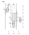
- the collision estimation area setting unit 112 sets the collision estimation area R1 ahead of the traveling direction D1 of the host vehicle VL1.
- the collision estimation area R1 when the preceding vehicles VL3 and VL4 do not satisfy the U-turn condition can be set to a substantially rectangular shape having a collision estimation area width RW1 and a collision estimation area length RL1, for example.
- the collision estimated area width RW1 is a length obtained in advance by experiments, and is preferably equal to or greater than the vehicle width of the host vehicle VL1.
- the collision estimated area width RW1 may be increased according to the relative speeds of the host vehicle VL1 and the preceding vehicles VL3 and VL4.
- the collision estimated area length RL1 can be calculated based on, for example, a map or a function in which the relationship between the relative speed between the host vehicle VL1 and the preceding vehicles VL3 and VL4 and the estimated collision area length RL1 obtained in advance through experiments is defined.
- the “relative speed” is positive when the preceding vehicles VL3 and VL4 are slower than the own vehicle VL1, and is minus when the preceding vehicles VL3 and VL4 are faster than the own vehicle VL1.
- the vertical axis represents the collision estimated area length RL1
- the horizontal axis represents the relative speed between the host vehicle VL1 and the preceding vehicles VL3 and VL4.
- the collision estimation region length RL1 extends as the relative speed increases.
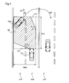
- the preceding vehicle VL2 shown in FIG. 7 is outside the vehicle width range W1 in front of the host vehicle VL1, the above-described condition 1 is satisfied. Further, the relative angle ⁇ formed by the intersection of the traveling direction D2 toward the opposite lane of the preceding vehicle VL2 and the traveling direction D1 of the host vehicle VL1 is equal to or greater than a predetermined threshold value, and satisfies the above-described condition 2 and condition 3 Yes. Accordingly, the preceding vehicle VL2 satisfies the U-turn conditions including the conditions 1 to 3.
- the collision estimation area R2 when the preceding vehicle VL2 satisfies the U-turn condition is set to be expanded from the collision estimation area R1 when the U-turn condition is not satisfied.
- the collision estimation area R2 is set to extend in a direction intersecting with the traveling direction D1 of the host vehicle VL1 and on the opposite side to the oncoming lane Ln3 than the collision estimation area R1.
- the collision estimation area R2 when the preceding vehicle VL2 satisfies the U-turn condition can be set to a substantially hexagonal shape by, for example, the collision estimation area width RW2, the collision estimation area length RL2, and the estimation area angles ⁇ 1 and ⁇ 2. More specifically, among the approximately rectangular corner portions formed by the estimated collision region width RW2 and the estimated collision region length RL2, a substantially triangular cutout is formed at the corner portion on the front end side and the opposite lane Ln3 side.
- the part C1 is deleted, and the substantially triangular notch part C2 is deleted at the corner part on the rear end side and opposite to the opposite lane Ln3.
- the notch C1 on the front end side when the preceding vehicle VL2 moves to the vicinity of the oncoming lane Ln3 by the U-turn, the possibility of colliding with the preceding vehicle VL2 is low. Can not.
- the notch C2 on the rear end side when the preceding vehicle VL2 is running side by side with the host vehicle VL1, the possibility of collision with the preceding vehicle VL2 is low, so it is estimated that there is a possibility of collision.
- the shape of the collision estimation region R2 may be set to a shape other than a substantially hexagon (for example, a substantially square).
- the collision estimation area length RL2 is based on, for example, a map or function in which the relationship between the relative speed between the host vehicle and another vehicle obtained in advance by experiment and the collision estimation area length RL1 is defined in the same manner as the collision estimation area length RL1. Can be calculated.
- the collision estimated area width RW2 can be calculated based on, for example, a map or a function in which the relationship between the yaw angular velocity of the preceding vehicle and the collision estimated area width RW2 obtained in advance by experiment is defined.
- the estimated area angles ⁇ 1 and ⁇ 2 can be calculated based on, for example, a map or function in which the relationship between the relative speed and the lateral speed of the preceding vehicle VL2 and the estimated area angles ⁇ 1 and ⁇ 2 is defined.
- the “relative speed” is the speed difference between the host vehicle VL1 and the preceding vehicle VL2 in the traveling direction D1 of the host vehicle VL1
- the “lateral speed” is the direction perpendicular to the traveling direction D1 of the host vehicle VL1. This is the speed of the preceding vehicle VL2.
- the estimated area angles ⁇ 1 and ⁇ 2 increase as the relative speed increases and the lateral speed decreases. Note that the estimated region angles ⁇ 1 and ⁇ 2 are preferably not less than 0 degrees and not more than 90 degrees. Further, the estimated area angle ⁇ 1 and the estimated area angle ⁇ 2 may be the same angle.
- the vertical axis represents the collision estimated area width RW2
- the horizontal axis represents the yaw angular velocity of the preceding vehicle VL2.
- the collision estimated region width RW2 extends as the yaw angular velocity of the preceding vehicle VL2 increases.
- step S130 the collision estimation unit 114 estimates whether or not there is a possibility of collision with the preceding vehicle. More specifically, it is determined whether or not at least a part of the preceding vehicle exists in the collision estimation area set in step S120 or S125. If it is estimated that there is no possibility of a collision, that is, if the preceding vehicle does not exist in the collision estimation area, the process returns to step S100. On the other hand, if it is estimated that there is a possibility of a collision, that is, if the preceding vehicle exists in the collision estimation area, the process proceeds to step S140, and the collision avoidance operation execution unit 116 executes a predetermined collision avoidance operation.
- the collision avoidance operation is performed by pre-crash safety (Pre Crash Safety (PCS (registered trademark))) control, warning and automatic brake for avoiding the collision, and automatic brake for reducing the impact caused by the collision. And automatic take-up of seat belts.
- Pre Crash Safety PCS (registered trademark)
- the collision avoidance operation execution unit 116 controls the notification unit 140 to warn the passenger of the vehicle that there is a possibility of a collision.
- the collision estimation area setting unit 112 expands the collision estimation area when the preceding vehicle does not satisfy the U-turn condition when the preceding vehicle satisfies the U-turn condition. Therefore, the possibility of collision can be estimated by predicting the U-turn of the preceding vehicle.
- a preceding vehicle VL2 that travels in the same traveling direction D1 as the host vehicle VL1 enters the oncoming lane Ln3 across a region where the host vehicle VL1 travels.
- the present invention is not limited to this.
- the present invention may be applied to a U-turn in which another vehicle traveling on the oncoming lane Ln3 enters the lane Ln2 on which the host vehicle VL1 travels.
- the collision estimation unit 114 sets the collision estimation region width RW2 according to the yaw angular velocity of the preceding vehicle VL2 in step S120.
- the collision estimation area width RW2 may be set according to the relative angle ⁇ of the preceding vehicle VL2, the increasing rate of the relative angle ⁇ , and the lateral speed of the preceding vehicle VL2. For example, when the relative angle ⁇ is large, the estimated collision region width RW2 can be set larger than when the relative angle ⁇ is small.
- the collision avoidance operation executing unit 116 determines the speed of the vehicle 100 based on the positional relationship between the preceding vehicle and the vehicle 100 existing in the collision estimation region as the above-described collision avoidance operation. You may perform the operation
- the present disclosure is not limited to the above-described embodiment, and can be realized with various configurations without departing from the spirit of the present disclosure.
- the technical features in the embodiments corresponding to the technical features in each embodiment described in the summary section of the invention are for solving the above-described problems or achieving some or all of the above-described effects.
- replacement and combination can be performed as appropriate.
- the technical feature is not described as essential in the present specification, it can be deleted as appropriate.
Landscapes
- Engineering & Computer Science (AREA)
- Automation & Control Theory (AREA)
- Transportation (AREA)
- Mechanical Engineering (AREA)
- Human Computer Interaction (AREA)
- Physics & Mathematics (AREA)
- General Physics & Mathematics (AREA)
- Traffic Control Systems (AREA)
- Control Of Driving Devices And Active Controlling Of Vehicle (AREA)
Priority Applications (1)
| Application Number | Priority Date | Filing Date | Title |
|---|---|---|---|
| US17/075,977 US11872983B2 (en) | 2018-04-23 | 2020-10-21 | Vehicle collision prediction apparatus |
Applications Claiming Priority (2)
| Application Number | Priority Date | Filing Date | Title |
|---|---|---|---|
| JP2018082089A JP7014032B2 (ja) | 2018-04-23 | 2018-04-23 | 車両衝突推定装置 |
| JP2018-082089 | 2018-04-23 |
Related Child Applications (1)
| Application Number | Title | Priority Date | Filing Date |
|---|---|---|---|
| US17/075,977 Continuation US11872983B2 (en) | 2018-04-23 | 2020-10-21 | Vehicle collision prediction apparatus |
Publications (1)
| Publication Number | Publication Date |
|---|---|
| WO2019208320A1 true WO2019208320A1 (ja) | 2019-10-31 |
Family
ID=68294936
Family Applications (1)
| Application Number | Title | Priority Date | Filing Date |
|---|---|---|---|
| PCT/JP2019/016263 Ceased WO2019208320A1 (ja) | 2018-04-23 | 2019-04-16 | 車両衝突推定装置 |
Country Status (3)
| Country | Link |
|---|---|
| US (1) | US11872983B2 (enExample) |
| JP (1) | JP7014032B2 (enExample) |
| WO (1) | WO2019208320A1 (enExample) |
Families Citing this family (12)
| Publication number | Priority date | Publication date | Assignee | Title |
|---|---|---|---|---|
| DE102017202415A1 (de) * | 2017-02-15 | 2018-08-16 | Bayerische Motoren Werke Aktiengesellschaft | Kollisionsvermeidung mit Querverkehr |
| DE102017223486A1 (de) * | 2017-12-21 | 2019-06-27 | Continental Teves Ag & Co. Ohg | Verfahren und System zum Vermeiden von lateralen Kollisionen |
| JP7014032B2 (ja) * | 2018-04-23 | 2022-02-01 | 株式会社デンソー | 車両衝突推定装置 |
| JP7497789B2 (ja) * | 2019-04-19 | 2024-06-11 | マツダ株式会社 | 車両制御装置 |
| US12269462B1 (en) * | 2020-03-16 | 2025-04-08 | Zoox, Inc. | Spatial prediction |
| KR20220092303A (ko) * | 2020-12-24 | 2022-07-01 | 현대자동차주식회사 | 차량 및 그 제어 방법 |
| JP7306419B2 (ja) * | 2021-03-26 | 2023-07-11 | いすゞ自動車株式会社 | 運転制御装置 |
| JP2022150605A (ja) | 2021-03-26 | 2022-10-07 | いすゞ自動車株式会社 | 運転制御装置 |
| KR102473714B1 (ko) * | 2021-05-07 | 2022-12-06 | 현대모비스 주식회사 | 객체를 감지하기 위한 차량 제어 시스템 및 그에 관한 방법 |
| CN115909813B (zh) * | 2022-12-06 | 2024-10-18 | 中国第一汽车股份有限公司 | 一种车辆碰撞预警方法、装置、设备及存储介质 |
| CN116118721A (zh) * | 2022-12-27 | 2023-05-16 | 苏州商力威科技有限公司 | 车辆控制方法、装置和电子设备 |
| CN115991160A (zh) * | 2023-02-02 | 2023-04-21 | 岚图汽车科技有限公司 | 区域控制器配置方法及相关设备 |
Citations (5)
| Publication number | Priority date | Publication date | Assignee | Title |
|---|---|---|---|---|
| JP2016130129A (ja) * | 2016-04-04 | 2016-07-21 | 株式会社小松製作所 | 運搬車両 |
| WO2017065212A1 (ja) * | 2015-10-14 | 2017-04-20 | 株式会社デンソー | 車両制御装置及び車両制御方法 |
| WO2017104773A1 (ja) * | 2015-12-17 | 2017-06-22 | 株式会社デンソー | 移動体制御装置及び移動体制御方法 |
| JP2017117343A (ja) * | 2015-12-25 | 2017-06-29 | 株式会社デンソー | 走行支援装置 |
| JP2018052328A (ja) * | 2016-09-29 | 2018-04-05 | ダイハツ工業株式会社 | 車両の制御装置 |
Family Cites Families (10)
| Publication number | Priority date | Publication date | Assignee | Title |
|---|---|---|---|---|
| JP2007099237A (ja) * | 2005-10-07 | 2007-04-19 | Fuji Heavy Ind Ltd | 車両用運転支援装置 |
| US7881868B2 (en) * | 2007-06-12 | 2011-02-01 | Palo Alto Research Center Incorporated | Dual assessment for early collision warning |
| JP5015849B2 (ja) | 2008-04-11 | 2012-08-29 | トヨタ自動車株式会社 | 逆走警告装置、逆走警告方法 |
| JP5407952B2 (ja) | 2009-06-18 | 2014-02-05 | 日産自動車株式会社 | 車両運転支援装置及び車両運転支援方法 |
| JP2016015043A (ja) | 2014-07-02 | 2016-01-28 | トヨタ自動車株式会社 | 対象物認識装置 |
| US9248834B1 (en) * | 2014-10-02 | 2016-02-02 | Google Inc. | Predicting trajectories of objects based on contextual information |
| WO2017056401A1 (ja) * | 2015-09-30 | 2017-04-06 | ソニー株式会社 | 制御装置、制御方法及びプログラム |
| JP6901555B2 (ja) * | 2017-06-02 | 2021-07-14 | 本田技研工業株式会社 | 自動運転車の制御のための車両制御装置及び方法 |
| US20190101924A1 (en) * | 2017-10-03 | 2019-04-04 | Uber Technologies, Inc. | Anomaly Detection Systems and Methods for Autonomous Vehicles |
| JP7014032B2 (ja) * | 2018-04-23 | 2022-02-01 | 株式会社デンソー | 車両衝突推定装置 |
-
2018
- 2018-04-23 JP JP2018082089A patent/JP7014032B2/ja active Active
-
2019
- 2019-04-16 WO PCT/JP2019/016263 patent/WO2019208320A1/ja not_active Ceased
-
2020
- 2020-10-21 US US17/075,977 patent/US11872983B2/en active Active
Patent Citations (5)
| Publication number | Priority date | Publication date | Assignee | Title |
|---|---|---|---|---|
| WO2017065212A1 (ja) * | 2015-10-14 | 2017-04-20 | 株式会社デンソー | 車両制御装置及び車両制御方法 |
| WO2017104773A1 (ja) * | 2015-12-17 | 2017-06-22 | 株式会社デンソー | 移動体制御装置及び移動体制御方法 |
| JP2017117343A (ja) * | 2015-12-25 | 2017-06-29 | 株式会社デンソー | 走行支援装置 |
| JP2016130129A (ja) * | 2016-04-04 | 2016-07-21 | 株式会社小松製作所 | 運搬車両 |
| JP2018052328A (ja) * | 2016-09-29 | 2018-04-05 | ダイハツ工業株式会社 | 車両の制御装置 |
Also Published As
| Publication number | Publication date |
|---|---|
| US20210031762A1 (en) | 2021-02-04 |
| JP2019188936A (ja) | 2019-10-31 |
| JP7014032B2 (ja) | 2022-02-01 |
| US11872983B2 (en) | 2024-01-16 |
Similar Documents
| Publication | Publication Date | Title |
|---|---|---|
| JP7014032B2 (ja) | 車両衝突推定装置 | |
| CN111942352B (zh) | 考虑转向路径的自适应aeb系统及其控制方法 | |
| US9669760B2 (en) | Warning device | |
| US20240270238A1 (en) | Vehicle for avoiding collision and method for operating the same | |
| JP6740969B2 (ja) | 車両における制動支援装置および制動支援制御方法 | |
| JP7435725B2 (ja) | 運転支援装置 | |
| CN103635946A (zh) | 驾驶辅助装置 | |
| US11299163B2 (en) | Control system of vehicle, control method of the same, and non-transitory computer-readable storage medium | |
| US11091174B2 (en) | Vehicle control device | |
| US12090998B2 (en) | Vehicle control apparatus | |
| US20220388502A1 (en) | Lateral movement system for collision avoidance | |
| CN112849133B (zh) | 驾驶支援装置 | |
| WO2019202859A1 (ja) | 走行制御装置 | |
| JP2023047007A (ja) | 車両の走行制御装置 | |
| US20210245753A1 (en) | Travel control apparatus, vehicle, travel control method, and non-transitory computer-readable storage medium | |
| US20200216096A1 (en) | Control system of vehicle, control method of the same, and non-transitory computer-readable storage medium | |
| US12043310B2 (en) | Driver assistance system and control method for the same | |
| JP4294450B2 (ja) | 車両用運転支援装置 | |
| JP2018090063A (ja) | 車両制御システム | |
| JP7676864B2 (ja) | 運転支援装置 | |
| US20240067173A1 (en) | Lane departure suppression device | |
| JP2023155454A (ja) | 運転支援装置及び通知装置 | |
| JP5267444B2 (ja) | 運転支援装置 | |
| JP7347340B2 (ja) | 走行制御装置および車両 | |
| WO2025205270A1 (ja) | 運転支援装置 |
Legal Events
| Date | Code | Title | Description |
|---|---|---|---|
| 121 | Ep: the epo has been informed by wipo that ep was designated in this application |
Ref document number: 19793369 Country of ref document: EP Kind code of ref document: A1 |
|
| NENP | Non-entry into the national phase |
Ref country code: DE |
|
| 122 | Ep: pct application non-entry in european phase |
Ref document number: 19793369 Country of ref document: EP Kind code of ref document: A1 |