WO2019203358A1 - ピストンリング - Google Patents
ピストンリング Download PDFInfo
- Publication number
- WO2019203358A1 WO2019203358A1 PCT/JP2019/016881 JP2019016881W WO2019203358A1 WO 2019203358 A1 WO2019203358 A1 WO 2019203358A1 JP 2019016881 W JP2019016881 W JP 2019016881W WO 2019203358 A1 WO2019203358 A1 WO 2019203358A1
- Authority
- WO
- WIPO (PCT)
- Prior art keywords
- ring
- axial direction
- gradually increasing
- outer peripheral
- piston ring
- Prior art date
Links
Images


Classifications
-
- F—MECHANICAL ENGINEERING; LIGHTING; HEATING; WEAPONS; BLASTING
- F02—COMBUSTION ENGINES; HOT-GAS OR COMBUSTION-PRODUCT ENGINE PLANTS
- F02F—CYLINDERS, PISTONS OR CASINGS, FOR COMBUSTION ENGINES; ARRANGEMENTS OF SEALINGS IN COMBUSTION ENGINES
- F02F5/00—Piston rings, e.g. associated with piston crown
-
- F—MECHANICAL ENGINEERING; LIGHTING; HEATING; WEAPONS; BLASTING
- F16—ENGINEERING ELEMENTS AND UNITS; GENERAL MEASURES FOR PRODUCING AND MAINTAINING EFFECTIVE FUNCTIONING OF MACHINES OR INSTALLATIONS; THERMAL INSULATION IN GENERAL
- F16J—PISTONS; CYLINDERS; SEALINGS
- F16J9/00—Piston-rings, e.g. non-metallic piston-rings, seats therefor; Ring sealings of similar construction
- F16J9/12—Details
- F16J9/14—Joint-closures
Definitions
- the present invention relates to a piston ring, and more particularly to a piston ring used for an internal combustion engine, a compression engine, or the like.
- the upper two or three piston rings which are the combustion chamber side, mainly maintain the airtightness between the combustion chamber and the crank chamber, and mainly have the function of transferring heat from the piston to the cylinder to dissipate heat. It is called “pressure ring”.
- the lower piston ring which is the crank chamber side, mainly has the function of forming an oil film on the cylinder inner surface and scraping off excess oil, and is generally called an “oil ring”. ing.
- a tapered face type piston ring having a tapered outer peripheral surface As an example of the pressure ring, a tapered face type piston ring having a tapered outer peripheral surface is known. Such a taper face type piston ring, by setting an appropriate taper angle, scrapes off oil adhering to the cylinder liner or the cylinder inner wall during the downward stroke of the piston, and a wedge effect between the tapered surface and the cylinder inner wall during the upward stroke. Thus, an oil film is formed. Because of these characteristics, the taper face type piston ring is mainly a second pressure ring (referred to as a “second ring” in the second position from the upper side) of the automobile engine or the second. It is used as a third pressure ring (a pressure ring arranged at the third position from the upper side and called a “third ring”).
- the pressure ring is provided with an abutment portion in which a predetermined abutment gap is formed.
- the outer peripheral surface of the pressure ring elastically contacts the inner wall of the cylinder with the piston fitted into the cylinder.
- the gas leak from between the outer peripheral surface of a pressure ring and a cylinder inner wall can be suppressed.
- gas may leak from the combustion chamber side to the crank chamber side through the abutment gap during operation of the internal combustion engine.
- oil may move to the combustion chamber side through the joint gap and be consumed.
- the abutment gap of the second pressure ring is made larger than the abutment gap of the first pressure ring (the pressure ring arranged at the first position from the upper side is called a “top ring”). It is known. By enlarging the joint gap of the second pressure ring, blow-by gas can be easily released through the joint gap of the second pressure ring during high load operation. Therefore, it is possible to suppress the accumulation of blow-by gas between the second land of the piston located between the first pressure ring and the second pressure ring and the cylinder inner wall. As a result, an increase in pressure due to blow-by gas at the position of the second land (hereinafter sometimes referred to as “second land pressure”) can be suppressed. Thereby, fluttering of the first pressure ring can be suppressed, and oil consumption and blow-by associated with fluttering can be reduced.
- Patent Document 1 discloses an engine piston ring structure in which the upper side of the joint gap of the second pressure ring is narrowed and the lower side is relatively wide.
- Patent Document 2 discloses a piston device for an internal combustion engine for the purpose of reducing oil consumption during high speed / high load operation and boost condition operation.
- the second pressure ring has a notch penetrating inward and outward in the lower surface of the joint portion.
- the joint gap of the second pressure ring in the notch is larger than the joint gap of the first pressure ring.
- the joint gap of the second pressure ring in the portion other than the notch is the same as or smaller than the joint gap of the first pressure ring.
- Patent Document 1 and Patent Document 2 it is possible to suppress an increase in the second land pressure and suppress an increase in oil consumption during high load operation, and also in an in-cylinder negative pressure environment.
- the oil can be prevented from moving toward the combustion chamber through the joint gap of the second pressure ring, but there is room for further improvement.
- the present invention when used as a second pressure ring or a third pressure ring, can suppress an increase in oil consumption during high load operation and in a cylinder negative pressure environment.
- An object is to provide a piston ring capable of suppressing uneven wear.
- the piston ring as the first aspect of the present invention is a sectional view along the axial direction, and a tapered portion that expands outward in the radial direction from the upper side to the lower side in the axial direction, and the shaft with respect to the tapered portion
- An outer peripheral surface having an outer peripheral top continuous in the lower side in the direction, and a gradually increasing region that gradually increases to the lower side surface toward the lower side in the axial direction is formed in the joint gap. It is provided only on the lower side in the axial direction than the outer peripheral top portion of the outer peripheral surface.
- an outer circumferential notch is formed over the entire region in the circumferential direction excluding the joint gap at a position below the outer circumferential top of the outer circumferential surface in the axial direction.
- the gradually increasing region is preferably provided in an axial region where the outer circumferential notch is formed.
- the gradually increasing region is provided over the entire region in the axial direction in which the outer circumferential notch is formed.
- the outer peripheral notch is formed by being cut out in a step shape or an undercut step shape in a sectional view along the axial direction.
- At least one abutment end surface portion forming the gradually increasing region is configured by an inclined surface inclined with respect to the axial direction.
- both the abutment end surface portions forming the gradually increasing region are constituted by the inclined surfaces.
- the inclined surface preferably includes a convex curved surface.
- the inclined surface and the lower surface are connected via a convex curved surface.
- the angle of the inclined surface with respect to the axial direction is preferably 30 to 80 degrees.
- the size of the abutment gap on the lower side is preferably 1.5 to 10 times the size of the abutment gap on the upper side.
- the joint gap gradually increases from the inside in the radial direction toward the outside in the gradually increasing region.
- the present invention when used as the second pressure ring or the third pressure ring, it is possible to suppress an increase in oil consumption during a high load operation and in a cylinder negative pressure environment.
- a piston ring capable of suppressing uneven wear of the groove can be provided.
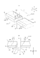
- FIG. 3A is an enlarged cross-sectional view showing the vicinity of the second ring shown in FIG. 2 further enlarged.
- FIG. 3B is a diagram illustrating a state in which the upper side surface of the second ring illustrated in FIG. 2 is in contact with the upper surface of the second ring groove.
- FIG. 3 is a top side view of a single second ring shown in FIG. 2. It is II sectional drawing of FIG. FIG. 6A is a perspective view showing the vicinity of the joint gap of the second ring in the assembled state.
- FIG. 6B is a front view of the abutment of the second ring in the assembled state as seen from the outer peripheral surface side to the front. It is a figure which shows the modification of the joint end surface part shown in FIG. It is a figure which shows the modification of the joint end surface part shown in FIG. It is a figure which shows the modification of the joint end surface part shown in FIG. It is a figure which shows the modification of the joint end surface part shown in FIG. It is a figure which shows the modification of the joint end surface part shown in FIG. It is a figure which shows the modification of the outer periphery notch part shown in FIG. It is a figure which shows the modification of the 2nd ring shown in FIG. It is a figure which shows the result of the confirmation experiment implemented using the engine which concerns on an Example. It is a figure which shows the result of the confirmation experiment implemented using the engine which concerns on an Example.
- FIG. 1 is a view showing a reciprocating engine (reciprocating internal combustion engine) as an internal combustion engine 1 having a piston ring as an embodiment.
- an internal combustion engine 1 includes a cylindrical cylinder 2 formed in a cylinder block 50, and an internal combustion engine piston 3 slidably accommodated in the cylinder 2 with an inner wall 2 a of the cylinder 2. (Hereinafter simply referred to as “piston 3”), a connecting rod 5 having an upper end coupled to the piston 3 via a piston pin 4, and a lower end of the connecting rod 5 via a crank pin 6.
- the crankshaft 7 is provided.
- the reciprocating engine as the internal combustion engine 1 shown in FIG. 1 is a gasoline engine in which the piston 3 can reciprocate in the vertical direction in the cylinder 2, but is another internal combustion engine such as a diesel engine in which the piston reciprocates. May be.
- the crankcase 8 is coupled to the lower side of the cylinder block 50, and the crankcase 9 for accommodating the crankshaft 7 is defined by the crankcase 8 and the lower portion of the cylinder block 50.
- An oil pan that receives oil dropped from above is provided on the lower side of the crankcase 8.
- a cylinder head 60 provided with an intake port 12 and an exhaust port 13 that are opened and closed by an intake valve 10 and an exhaust valve 11, respectively, is coupled to the upper side of the cylinder block 50, and the inner wall surface of the cylinder head 60 and the upper surface of the piston 3 are connected. And the inner peripheral surface of the cylinder 2 define a combustion chamber 14.
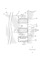
- FIG. 2 is an enlarged cross-sectional view showing a part of the cross-section parallel to the central axis O of the piston 3 shown in FIG.
- the piston 3 includes a piston main body 16 in which a ring groove 15 is formed on the outer peripheral surface, and a piston ring 17 disposed in the ring groove 15.
- a plurality of ring grooves 15 are formed in the piston body 16 of the present embodiment. More specifically, three ring grooves 15 of a first ring groove 15a, a second ring groove 15b, and a third ring groove 15c are formed on the outer peripheral surface of the piston body 16 of the present embodiment.
- the first ring groove 15a is parallel to the center axis O of the piston 3 (same as the center axis of the piston body 16) (hereinafter referred to as “center axis direction A”), and the second ring groove 15b and the second ring groove 15a. It is located closer to the crown surface of the piston body 16 than the three ring grooves 15c. In other words, the first ring groove 15 a is located at the uppermost position in the central axis direction A among the plurality of ring grooves 15.
- the second ring groove 15b is located between the first ring groove 15a and the third ring groove 15c in the central axis direction A.
- the third ring groove 15c is located on the lower end side of the piston body 16 in the central axis direction A with respect to the second ring groove 15b and the third ring groove 15c. In other words, the third ring groove 15 c is located at the lowest position in the central axis direction A among the plurality of ring grooves 15.
- one piston ring 17 is disposed in each of the first ring groove 15a and the second ring groove 15b.
- one piston ring 17 made of three parts is disposed in the third ring groove 15c of the three ring grooves 15. More specifically, the first ring 17a is fitted and disposed in the first ring groove 15a. A second ring 17b is fitted in the second ring groove 15b. The third ring 17c is fitted in the third ring groove 15c.
- the first ring 17a is a so-called “first pressure ring” and suppresses the escape of compressed gas (blow-by gas) from the combustion chamber 14 side to the crankcase 8 side. Specifically, the outer circumference of the first ring 17a slides under a predetermined pressure through the inner wall 2a of the cylinder 2 and the lubricating oil, thereby suppressing the generation of the blow-by gas described above.
- the third ring 17 c is a so-called “oil ring”, and scrapes off excess engine oil attached to the inner wall 2 a of the cylinder 2 to form an appropriate oil film, thereby preventing the piston 3 from burning. .
- the third ring 17c forms an appropriate oil film on the inner wall 2a of the cylinder 2 by sliding its outer peripheral surface with the inner wall 2a of the cylinder 2 under a predetermined pressure.
- the third ring 17c can be realized by various configurations.
- the second ring 17b is a so-called “second pressure ring”, which assists the first ring 17a, which is the first pressure ring, and suppresses the generation of the blow-by gas described above. Furthermore, the second ring 17b also has a function of assisting the third ring 17c that is an oil ring. That is, the outer peripheral surface of the second ring 17b slides under a predetermined pressure through the inner wall 2a of the cylinder 2 and the lubricating oil, thereby suppressing the above-described blow-by gas, while maintaining an excess on the inner wall 2a of the cylinder 2. The engine oil is scraped off.
- the piston body 16 of the piston 3 is made of an aluminum alloy, and the piston ring 17 is made of steel, cast iron, or resin.
- FIG. 3A is an enlarged cross-sectional view showing the vicinity of the second ring 17b of FIG. 2 further enlarged.
- FIG. 3A shows a state in which the lower surface 17b1 of the second ring 17b is in contact with the lower surface 15b1 of the second ring groove 15b, for example, in the operation stroke of the internal combustion engine 1 (see FIG. 1).
- the blow-by gas staying at the position of the second land 31 of the piston 3 is transferred to the third land 32 side of the piston 3 even in the state shown in FIG. Easy to escape and reduce oil consumption. Specifically, as indicated by an arrow in FIG.
- the second ring 17b is disposed between the upper surface 17b2 of the second ring 17b and the upper surface 15b2 of the second ring groove 15b, and the inner peripheral surface 17b3 of the second ring 17b and the second surface.
- FIG. 3B shows a state in which the upper side surface 17b2 of the second ring 17b is in contact with the upper surface 15b2 of the second ring groove 15b, for example, in the operation stroke of the internal combustion engine 1 (see FIG. 1). Yes.
- the oil is moved from the crank chamber 9 (see FIG. 1) side to the combustion chamber 14 (see FIG. 1) side. Oil consumption can be reduced. Details of this will be described later.
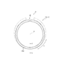
- FIG. 4 is a top side view of a single second ring 17b. More specifically, in FIG. 4, the second ring 17b in a free state where no external force before being incorporated into the cylinder 2 is indicated by a broken line, is accommodated in the cylinder 2 together with the piston main body 16, and the cylinder 2
- the second ring 17b in a state in which an external force is applied and tensioned from the inner wall 2a, in other words, in a state in which the cylinder 2 is closed to the inner diameter (hereinafter, sometimes simply referred to as “assembled state”) is indicated by a solid line. It shows by.
- the second ring 17b is provided with an abutment 21.
- a joint gap 20 is formed in the joint part 21 of the second ring 17 b in the assembled state.
- FIG. 5 is a cross-sectional view taken along the line II of FIG. 4, in other words, a cross-sectional view of the second ring 17b perpendicular to the circumferential direction B of the single unit.
- the second ring 17b of the present embodiment includes an outer peripheral surface 17b4 that slides through the inner wall 2a of the cylinder 2 and the lubricating oil.
- the outer peripheral surface 17b4 of the second ring 17b is in the axial direction of the second ring 17b (because it is the same direction as the central axial direction A, hereinafter simply referred to as “axial direction A”).
- axial direction A In a cross-sectional view along, a tapered portion 18 that expands outward in the radial direction C from the upper side to the lower side in the axial direction A, and an outer peripheral top portion 19 that continues to the lower side in the axial direction A with respect to the tapered portion 18. I have.
- the axial direction A shown in FIG. 5 is the axial direction of the second ring 17b in a free state.
- the above-described tapered portion 18 is formed at a position continuous from the upper side surface 17b2 of the second ring 17b.
- a ridge portion as the outer peripheral top portion 19 is formed at the lower end position of the tapered portion 18.
- the position of the taper part 18 of the outer peripheral surface 17b4 is not limited to the position of the present embodiment, and may be formed at a position that is not continuous with the upper side surface 17b2 of the second ring 17b.
- the outer peripheral top portion 19 is not limited to the configuration of the present embodiment.
- the outer peripheral top portion 19 is connected to the tapered portion 18 and is configured by a peripheral surface having a uniform outer diameter regardless of the position in the axial direction A. It is good.
- the outer peripheral surface 17b4 of the second ring 17b of the present embodiment is a so-called “tapered face surface” configured by the tapered portion 18 and the outer peripheral top portion 19 described above, but includes surfaces other than the tapered portion 18 and the outer peripheral top portion 19. It may be configured.
- the inner peripheral surface 17b3 of the second ring 17b is constituted by a peripheral surface having a substantially uniform inner diameter regardless of the position in the axial direction A in the free state of the second ring 17b.
- the lower side surface 17b1 and the upper side surface 17b2 of the second ring 17b are configured by planes substantially parallel to the direction orthogonal to the axial direction A in the free state of the second ring 17b.
- a direction from the lower side surface 17b1 to the upper side surface 17b2 in the axial direction A is simply referred to as “upper side of the axial direction A”
- a direction from the upper side surface 17b2 to the lower side surface 17b1 in the axial direction A is simply “ The lower side of the axial direction A is described.
- the “upper side in the axial direction A” referred to here means the combustion chamber 14 (see FIG.
- An outer circumferential notch 22 is formed over the entire region in the circumferential direction B excluding the joint gap 20 at a position below the outer circumferential top portion 19 of the outer circumferential surface 17b4 of the second ring 17b of the present embodiment in the axial direction A. ing.
- the outer circumferential notch 22 of the present embodiment is formed by being cut out in a step shape in a sectional view along the axial direction A (see FIG. 5 and the like). Therefore, the lower surface 17b1 and the outer peripheral surface 17b4 of the second ring 17b of the present embodiment are connected via the outer peripheral notch 22 in the cross-sectional view shown in FIG.
- deletion part 23 is formed over the whole area of the circumferential direction B except the joint gap 20 in the position below the axial direction A of the internal peripheral surface 17b3 of the 2nd ring 17b of this embodiment. Therefore, the lower surface 17b1 and the inner peripheral surface 17b3 of the second ring 17b of the present embodiment are connected via the defect portion 23 in the cross-sectional view shown in FIG. Note that the second ring 17b may have a configuration in which the defect portion 23 is not formed. Further, in order to reduce the twist in the assembled state of the second ring 17b, for example, a defective portion may be formed at a position on the upper side in the axial direction A of the outer peripheral surface 17b4 of the second ring 17b.
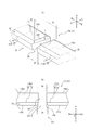
- FIG. 6A is a perspective view showing the vicinity of the joint gap 20 of the assembled second ring 17b.
- FIG. 6A shows the lower surface 17b1 side of the assembled second ring 17b.
- FIG. 6B is a front view of the joint portion 21 of the second ring 17b in the assembled state when viewed from the outer peripheral surface side.
- the joint gap 20 is formed with a gradually increasing region E that gradually increases to the lower side surface 17b1 toward the lower side in the axial direction A. Further, as shown in FIGS. 6A and 6B, the gradually increasing region E is provided only on the lower side in the axial direction A than the outer peripheral top portion 19 of the outer peripheral surface 17b4 of the second ring 17b.
- the size of the joint gap at the lower side surface 17b1 becomes a joint at the upper side surface.
- oil up can be suppressed both during high-load operation and in an in-cylinder negative pressure environment.
- the second ring 17b is pressed against the lower surface 15b1 of the second ring groove 15b by the combustion pressure (see FIG. 3A).
- the combustion gas flows between the upper surface 17b2 of the second ring 17b and the upper surface 15b2 of the second ring groove 15b, the inner peripheral surface 17b3 of the second ring 17b, and the bottom surface 15b3 of the second ring groove 15b.
- And passes through a wide portion on the lower surface 17b1 side of the joint gap 20 to flow toward the crank chamber 9 (see FIG. 1).
- the combustion chamber 14 in the combustion stroke during high load operation.
- the high-pressure gas (see FIG. 1) can easily escape to the crank chamber 9 (see FIG. 1) side.
- fluttering of the first ring 17a (see FIG. 2) due to the increase in the second land pressure can be suppressed, and backflow of gas to the combustion chamber 14 (see FIG. 1) side can be suppressed.
- oil consumption due to oil up to the combustion chamber 14 (see FIG. 1) side due to the back flow of the gas can be suppressed.
- the high-pressure gas in the combustion chamber 14 escapes to the crank chamber 9 (see FIG. 1) side, so that an oil blowing-down effect can be obtained. Oil consumption can also be suppressed in this respect.
- the second ring 17b is in contact with the upper surface 15b2 of the second ring groove 15b in an in-cylinder negative pressure environment where the pressure in the combustion chamber 14 (see FIG. 1) decreases. (See FIG. 3B).
- the oil hardly moves from the crank chamber 9 (see FIG. 1) side to the combustion chamber 14 (see FIG. 1) side through the abutment gap 20.
- the size S2 of the joint gap 20 on the upper side surface 17b2 narrower than the size S1 of the joint gap 20 on the lower side surface 17b1, oil consumption due to oil up through the joint gap 20 can be suppressed.
- a gradually increasing region E that gradually increases to the lower side surface 17b1 toward the lower side in the axial direction A is formed in the joint gap 20. Providing such a gradually increasing region E makes it difficult for the edge on the lower surface 17b1 side of the abutment gap 20 to be caught on the lower surface 15b1 of the second ring groove 15b, thereby causing uneven wear of the second ring 17b and the second ring groove 15b. Can be suppressed.
- the gradually increasing region E is provided only below the outer peripheral top portion 19 of the outer peripheral surface 17b4 of the second ring 17b in the axial direction A, a part of the outer peripheral top portion 19 is positioned adjacent to the joint gap 20. Can be prevented from being lost. Therefore, adhesion between the outer peripheral top 19 and the inner wall 2a of the cylinder 2 can be maintained at a position adjacent to the joint gap 20.
- the outer circumferential notch portion 22 is formed at a position below the outer circumferential top portion 19 of the outer circumferential surface 17b4 of the second ring 17b in the axial direction A.
- region E of this embodiment is provided in the axial direction area
- the lower surface 17b1 of the second ring 17b is in pressure contact with the lower surface 15b1 of the second ring groove 15b (see FIG. 3A), from a position near the second land 31.
- the gradually increasing region of the joint gap 20 is between the upper side surface 17b2 of the second ring 17b and the upper surface 15b2 of the second ring groove 15b, between the inner peripheral surface 17b3 of the second ring 17b and the bottom surface 15b3 of the second ring groove 15b.
- the blow-by gas that sequentially travels through E is released at the position of the outer circumferential notch 22.
- the gradually increasing region E of the present embodiment is provided over the entire region in the axial direction in which the outer circumferential notch 22 is formed. More specifically, as shown in FIG. 6 (b), the outer circumferential notch portion 22 of the present embodiment is formed in the entire region below the axial direction A with respect to the circumferential ridge portion as the outer circumferential top portion 19. Has been. Therefore, the gradually increasing region E of the present embodiment is formed in the entire region below the axial direction A with respect to the circumferential ridge portion as the outer peripheral top portion 19.
- the length of the gradually increasing region E in the axial direction A can be secured, and a wide passage area of blow-by gas can be secured. Therefore, the increase in the second land pressure can be further suppressed. As a result, the backflow of gas due to the increase in the second land pressure can be further suppressed, and the oil consumption accompanying this backflow of gas can be further suppressed.
- one abutment end surface portion 24 that forms the gradually increasing region E of the present embodiment is configured by an inclined surface that is inclined with respect to the axial direction A. More specifically, in the present embodiment, one abutment end face portion 24 is an inclined surface that is inclined with respect to the axial direction A, and the other abutment end face portion 25 is standing substantially parallel to the axial direction A. In this manner, by forming the gradually increasing region E in a triangular shape including an inclined surface, it becomes easy to process and productivity can be improved.
- the size S1 on the lower side surface 17b1 of the joint gap 20 is preferably 1.5 to 10 times the size S2 on the upper side surface 17b2 of the joint gap 20. More preferably 5 times. If it is smaller than 1.5 times, the high-pressure gas from the combustion chamber 14 (see FIG. 1) side is difficult to escape, and the effect of suppressing the second land pressure cannot be sufficiently exhibited. If it exceeds ten times, the second ring 17b is likely to be lifted by the inertial force in the vicinity of bottom dead center due to the wraparound of the combustion gas, and the side sealability of the second ring 17b may be deteriorated, and the oil consumption is reduced. The effect cannot be fully demonstrated.
- S1 and S2 in the present embodiment are substantially constant regardless of the position in the radial direction C, but when they vary depending on the position in the radial direction C, the size S1 and the upper side of the lower surface of the joint gap
- the size S2 on the side surface means a value at a position where the facing distance is minimum, that is, a minimum value of the facing distance (see FIG. 10).
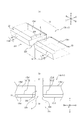
- FIG. 7 is a view showing a modification of the joint end surface portions 24 and 25 of the present embodiment.
- FIG. 7A is a perspective view showing the vicinity of the joint gap 120 of the assembled second ring 17b.
- FIG. 7A shows the lower surface 17b1 side of the assembled second ring 17b.
- FIG. 7B is a front view of the joint portion 121 of the second ring 17b in the assembled state when viewed from the outer peripheral surface side.
- the abutment portion 121 shown in FIG. 7 is different from the abutment portion 21 shown in FIG. 6 in the shape of the abutment end surface portion, and the other configurations are the same. Therefore, this difference is mainly described here. A description of the common configuration will be omitted.
- Both the abutment end surface portions 124 and 125 forming the gradually increasing region E shown in FIG. 7 are configured by inclined surfaces inclined with respect to the axial direction A. More specifically, the facing abutment end surface portions 124 and 125 shown in FIG. 7 are inclined so that the facing distance is separated from the lower side in the axial direction A. In this way, by forming both the abutment end surface portions 124 and 125 forming the gradually increasing region E with inclined surfaces that are separated from each other toward the lower side in the axial direction A, only one of the abutment end surface portions is formed. Compared with the case where it comprises with the inclined surface which inclines with respect to the axial direction A, the gradually increasing area
- FIG. 8 is a view showing another modified example of the above-described joint end surface portions 24 and 25.
- FIG. 8A is a perspective view showing the vicinity of the joint gap 220 of the assembled second ring 17b.
- FIG. 8A shows the lower surface 17b1 side of the assembled second ring 17b.
- FIG. 8B is a front view of the joint 221 of the second ring 17b in the assembled state as viewed from the outer peripheral surface side.
- the abutment portion 221 shown in FIG. 8 is different from the abutment portion 121 shown in FIG. 7 in the shape of the abutment end surface portion, and the other configurations are the same. Therefore, this difference is mainly described here. A description of the common configuration will be omitted.
- Both the abutment end surface portions 224 and 225 forming the gradually increasing region E shown in FIG. 8 are configured by inclined surfaces that are inclined with respect to the axial direction A, like the abutment end surface portions 124 and 125 of FIG. Furthermore, the inclined surfaces constituting both the abutting end surface portions 224 and 225 forming the gradually increasing region E shown in FIG. 8 are formed by convex curved surfaces. Thus, you may comprise both the joint end surface parts 224 and 225 which form the gradual increase area
- abutment end surface portion 24 may be formed of a convex curved surface. Therefore, in the abutment portion 21 in which only one abutment end surface portion 24 shown in FIG. 6 is constituted by an inclined surface, the abutment end surface portion 24 may be constituted by a convex curved surface.
- FIG. 9 is a view showing still another modified example of the above-described joint end surface portions 24 and 25.
- FIG. 9A is a perspective view showing the vicinity of the joint gap 320 of the second ring 17b in the assembled state.
- FIG. 9A shows the lower surface 17b1 side of the assembled second ring 17b.
- FIG. 9B is a front view of the joint portion 321 of the second ring 17b in the assembled state when viewed from the outer peripheral surface side.
- the abutment portion 321 shown in FIG. 9 is different from the abutment portion 221 shown in FIG. 8 in the shape of the abutment end surface portion, and the other configurations are the same. Therefore, this difference is mainly described here. A description of the common configuration will be omitted.
- Both the abutment end surface portions 324 and 325 forming the gradually increasing region E shown in FIG. 9 are configured by inclined surfaces that are inclined with respect to the axial direction A, like the abutment end surface portions 224 and 225 of FIG. Furthermore, the inclined surfaces constituting both the abutting end surface portions 324 and 325 forming the gradually increasing region E shown in FIG. 9 are configured by planes.
- the inclined surfaces constituting the joint end surface portions 324 and 325 and the lower side surface 17b1 are connected via a convex curved surface 326.
- the abutment end surface portions 324 and 325 and the lower side surface 17b1 can be smoothly continued by the convex curved surface 326.
- the edge on the lower surface 17b1 side of the joint gap 220 is less likely to be caught on the lower surface 15b1 (see FIG. 3) of the second ring groove 15b (see FIG. 3), and the second ring 17b and the second ring groove 15b.
- the uneven wear can be further suppressed.
- FIG. 10 is a view showing still another modified example of the above-described joint end surface portions 24 and 25.
- FIG. 10A is a perspective view showing the vicinity of the joint gap 420 of the second ring 17b in the assembled state.
- FIG. 10A shows the lower surface 17b1 side of the assembled second ring 17b.
- FIG. 10B is a front view of the abutment portion 421 of the second ring 17b in the assembled state as viewed from the outer peripheral surface side.
- the abutment portion 421 shown in FIG. 10 is different from the abutment portion 121 shown in FIG. 7 in the shape of the abutment end surface portion, and the other configurations are the same. Therefore, this difference is mainly described here. A description of the common configuration will be omitted.
- Both the abutment end surface portions 424 and 425 forming the gradually increasing region E shown in FIG. 10 are configured by inclined surfaces that are inclined with respect to the axial direction A, like the abutment end surface portions 124 and 125 of FIG. Further, the inclined surfaces constituting both the abutting end surface portions 424 and 425 forming the gradually increasing region E shown in FIG. 10 are configured by a plane, like the abutting end surface portions 124 and 125 of FIG. However, the abutment gap 420 shown in FIG. 10 gradually increases from the inside in the radial direction C toward the outside in the gradually increasing region E.
- the angle ⁇ with respect to the axial direction A of the portion constituted by a flat surface among the inclined surfaces constituting the joint end surface portion shown in FIGS. 6, 7, and 9 is preferably 30 ° to 80 °, more preferably 30 ° to More preferably, the angle is 60 degrees.
- outer circumferential notch 22 shown in FIGS. 6 to 10 is formed by being cut out in a step shape in a sectional view along the axial direction A.
- the present invention is not limited to this configuration, and as shown in FIG.
- the outer periphery notch part 22 formed by notching in an undercut step shape in the same sectional view may be used.
- the second ring 17b made of cast iron or resin is shown, but a second ring 17b made of steel as shown in FIG. 12 may be used.
- the outer peripheral surface 17b4 of the second ring 17b in FIG. 12B includes a first taper portion 18a continuous with the upper side surface 17b2 from the upper side in the axial direction A, and a lower side in the axial direction A of the first taper portion 18a.
- a second taper portion 18b continuous to the side, and an outer peripheral top portion 19 located on the lower side in the axial direction A of the second taper portion 18b.
- the outer peripheral surface 17b4 provided with the some taper part from which the angle which inclines with respect to the axial direction A differs may be sufficient.
- the engine used as an embodiment is an in-line four-cylinder four-cycle gasoline engine in which the bore diameter, which is the inner diameter of the cylinder 2 (see FIG. 1), is 78 [mm] and the displacement is 1.5 [L]. It is.
- This gasoline engine takes in the cylinder 2 by natural intake by atmospheric pressure without using a turbocharger or the like.
- the gasoline engine is configured to inject fuel into the intake port 12 (see FIG. 1) of each cylinder 2.
- a first ring 17a (see FIG. 2), a second ring 17b (see FIG. 2), and a third ring 17c (see FIG. 2) are used.
- the first ring 17a the ring width (length in the axial direction) is 1.2 [mm]
- the ring thickness (length in the radial direction) is 2.5 [mm]
- the joint gap in the assembled state is 0. .20 [mm] and tension of 5 [N] are used.
- the second ring 17b has a ring width (axial length) of 1.0 [mm], a ring thickness (radial length) of 2.5 [mm], and a tension of 3 [N]. Is used. Regarding the joint gap 20 (see FIG. 6 and the like) in the assembled state of the second ring 17b, the size at the upper side surface 17b2 (see FIG. 6 and the like) with respect to the size S1 at the lower side surface 17b1 (see FIG. 6 and the like). The following seven types of samples having a reduced length S2 were prepared and a confirmation experiment was performed (see [Table 1]).
- the ring width (length in the axial direction) is 2.0 [mm]
- the combined ring thickness (length in the radial direction) is 2.2 [mm]
- the joint gap in the assembled state is The one with 0.30 [mm] and tension of 8 [N] is used.
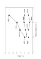
- FIG. 13 shows a confirmation experiment for measuring the oil consumption at the full load (6000 [rpm]) as a high speed and high load operation performed on an engine including each of the 11 types of second rings shown in [Table 1]. It is a figure which shows a result.
- the oil consumption of the engine of Comparative Example 1 is “1”. That is, in FIG. 13, the oil consumption of Examples 1 to 7 and Comparative Examples 2 to 4 is shown as a ratio to the oil consumption of Comparative Example 1.
- FIG. 14 is a diagram showing a result of a confirmation experiment for measuring an oil consumption amount in an acceleration / deceleration operation mode in which the combustion chamber has a negative pressure, which is performed on an engine including each of the 11 types of second rings shown in [Table 1]. It is.
- the oil consumption can be reduced by making the size S2 of the joint gap 20 on the upper side surface 17b2 smaller than the size S1 of the joint gap 20 on the lower side surface 17b1. This is considered to be because the oil up in which oil is sucked from the position of the third land portion to the combustion chamber side in the intake stroke can be suppressed.
- the size S1 of the joint gap 20 on the lower side surface 17b1 is increased, and the size S2 of the joint gap 20 on the upper side surface 17b2 is made smaller than the size S1 of the joint gap 20 on the lower side surface 17b1. Oil consumption during high speed and high load operation can be suppressed.
- the piston ring according to the present invention is not limited to the specific configurations shown in the above-described embodiments and modifications, and various modifications and changes can be made without departing from the description of the claims.
- the piston ring according to the present invention may be used as a third ring in an internal combustion engine having four rings (top ring, second ring, third ring, oil ring). That is, it is good also as a structure which provides the above-mentioned gradually increasing area
- the present invention relates to a piston ring, and more particularly to a piston ring used for an internal combustion engine, a compression engine, or the like.
Landscapes
- Engineering & Computer Science (AREA)
- General Engineering & Computer Science (AREA)
- Mechanical Engineering (AREA)
- Chemical & Material Sciences (AREA)
- Combustion & Propulsion (AREA)
- Pistons, Piston Rings, And Cylinders (AREA)
Abstract
本発明に係るピストンリングは、軸方向に沿う断面視で、前記軸方向の上側から下側に向かうにつれて径方向の外側に拡がるテーパ部と、前記テーパ部に対して前記軸方向の下側で連続する外周頂部と、を備える外周面を備え、合口隙間には、前記軸方向の下側に向かって下側面まで漸増する漸増領域が形成されており、前記漸増領域は、前記外周面の前記外周頂部よりも前記軸方向の下側のみに設けられている。
Description
本発明はピストンリングに関し、特に、内燃機関、圧縮機関等に使用されるピストンリングに関する。
内燃機関のピストンには、3~4本のピストンリングが装着される。燃焼室側である上側の2~3本のピストンリングは、燃焼室とクランク室との気密を保持すると共に、ピストンの熱をシリンダに伝達して放熱する機能を主に有し、一般的に「圧力リング」と呼ばれている。また、クランク室側である下側の1本のピストンリングは、シリンダ内面に油膜を形成し、かつ、過剰なオイルを掻き落とす機能を主に有し、一般的に「オイルリング」と呼ばれている。
圧力リングの一例として、テーパ形状の外周面を有するテーパフェイス形のピストンリングが知られている。このようなテーパフェイス形のピストンリングは、適正なテーパ角度の設定により、ピストンの下降行程時にはシリンダライナ又はシリンダ内壁に付着するオイルを掻き落とすと共に、上昇行程時にはテーパ面とシリンダ内壁間のくさび効果により油膜を形成するという特徴を有している。このような特徴から、テーパフェイス形のピストンリングは、主に、自動車エンジンの第2圧力リング(上側から2番目の位置に配置される圧力リングで「セカンドリング」と呼ばれている。)又は第3圧力リング(上側から3番目の位置に配置される圧力リングで「サードリング」と呼ばれている。)として利用されている。
また、圧力リングには、所定の合口隙間が形成されている合口部が設けられている。この合口部を設けることにより、圧力リングの外周面が、ピストンをシリンダに嵌合した状態で、シリンダ内壁に弾発的に接触する。これにより、圧力リングの外周面と、シリンダ内壁と、の間からのガス漏れを抑制することができる。しかしながら、合口部を設けることで、内燃機関の運転時において、合口隙間を通じて、燃焼室側からクランク室側へとガスが漏れることがある。更に、合口隙間を通じて、オイルが燃焼室側へと移動し、消費されることがある。
これらの対策として、第2圧力リングの合口隙間を、第1圧力リング(上側から1番目の位置に配置される圧力リングで「トップリング」と呼ばれている。)の合口隙間よりも大きくすることが知られている。第2圧力リングの合口隙間を大きくすることで、高負荷運転時に、第2圧力リングの合口隙間を通じてブローバイガスを抜け易くすることができる。そのため、第1圧力リング及び第2圧力リングの間に位置するピストンの第2ランドと、シリンダ内壁と、の間にブローバイガスが溜まることを抑制することができる。その結果、第2ランドの位置でのブローバイガスによる圧力(以下「第2ランド圧」と記載する場合がある。)の上昇が抑制できる。これにより、第1圧力リングのフラッタリングを抑制することができると共に、フラッタリングに伴うオイル消費やブローバイについても低減することができる。
しかしながら、自動車の減速のためにエンジンブレーキを使用した際などは、筒内負圧状態が発生し、第2圧力リングの合口隙間を大きくした分、第2圧力リングの合口隙間を通じて、オイルが燃焼室側へと移動し易く、オイル消費が増大するおそれがある。
これに対して、特許文献1には、第2圧力リングの合口隙間の上側を狭くし、下側を相対的に広く形成させたエンジンのピストンリング構造が開示されている。
また、特許文献2では、高速・高負荷運転時及びブースト条件運転時においてオイル消費を少なくすることを目的とした内燃機関用ピストン装置が開示されている。特許文献2に記載の内燃機関用ピストン装置では、第2圧力リングが、合口部の下面に内外に貫通する切欠きを有する。この切欠き部における第2圧力リングの合口隙間は、第1圧力リングの合口隙間よりも大きい。また、切欠き部以外の部分における第2圧力リングの合口隙間は、第1圧力リングの合口隙間と同じか又は小さい。
特許文献1及び特許文献2に開示されている構成によれば、高負荷運転時において、第2ランド圧の上昇を抑制し、オイル消費の増大を抑制できると共に、筒内負圧環境下においても、第2圧力リングの合口隙間を通じて燃焼室側にオイルが移動することを抑制することができるが、更なる改善の余地がある。
本発明は、第2圧力リング又は第3圧力リングとして使用される場合に、高負荷運転時及び筒内負圧環境下においてオイル消費が増大することを抑制可能であり、更には、リング溝の偏摩耗をも抑制可能な、ピストンリングを提供することを目的とする。
本発明の第1の態様としてのピストンリングは、軸方向に沿う断面視で、前記軸方向の上側から下側に向かうにつれて径方向の外側に拡がるテーパ部と、前記テーパ部に対して前記軸方向の下側で連続する外周頂部と、を備える外周面を備え、合口隙間には、前記軸方向の下側に向かって下側面まで漸増する漸増領域が形成されており、前記漸増領域は、前記外周面の前記外周頂部よりも前記軸方向の下側のみに設けられていることを特徴とするものである。
本発明の1つの実施形態としてのピストンリングは、前記外周面の前記外周頂部よりも前記軸方向の下側の位置に、前記合口隙間を除く周方向の全域に亘って外周切欠き部が形成されており、前記漸増領域は、前記外周切欠き部が形成されている軸方向領域内に設けられていることが好ましい。
本発明の1つの実施形態として、前記漸増領域は、前記外周切欠き部が形成されている前記軸方向領域の全域に亘って設けられていることが好ましい。
本発明の1つの実施形態として、前記外周切欠き部は、前記軸方向に沿う断面視で、ステップ状又はアンダカットステップ状に切欠かれて形成されていることが好ましい。
本発明の1つの実施形態として、前記漸増領域を形成する少なくとも一方の合口端面部は、前記軸方向に対して傾斜する傾斜面により構成されていることが好ましい。
本発明の1つの実施形態として、前記漸増領域を形成する両方の前記合口端面部は、前記傾斜面により構成されていることが好ましい。
本発明の1つの実施形態として、前記傾斜面は、凸形の曲面を含むことが好ましい。
本発明の1つの実施形態として、前記傾斜面と前記下側面とは、凸形の曲面を介して連なっていることが好ましい。
本発明の1つの実施形態として、前記傾斜面の前記軸方向に対する角度は、30度~80度であることが好ましい。
本発明の1つの実施形態として、前記合口隙間の前記下側面での大きさは、前記合口隙間の上側面での大きさに対して、1.5~10倍であることが好ましい。
本発明の1つの実施形態として、前記合口隙間は、前記漸増領域において、前記径方向の内側から外側に向かって漸増していることが好ましい。
本発明によれば、第2圧力リング又は第3圧力リングとして使用される場合に、高負荷運転時及び筒内負圧環境下においてオイル消費が増大することを抑制可能であり、更には、リング溝の偏摩耗をも抑制可能な、ピストンリングを提供することができる。
以下、本発明に係るピストンリングの実施形態について、図1~図14を参照して説明する。各図において共通する部材・部位には同一の符号を付している。
図1は、本実施形態としてのピストンリングを備える、内燃機関1としてのレシプロエンジン(往復動内燃機関)を示す図である。図1に示すように、内燃機関1は、シリンダブロック50に形成された円筒状のシリンダ2と、このシリンダ2内でシリンダ2の内壁2aと摺動可能に収容されている内燃機関用ピストン3(以下、単に「ピストン3」と記載する。)と、ピストンピン4を介してピストン3に上端部が結合されたコネクティングロッド5と、クランクピン6を介してコネクティングロッド5の下端部に連結されたクランクシャフト7と、を備えている。なお、図1に示す内燃機関1としてのレシプロエンジンは、ピストン3がシリンダ2内で上下方向に往復移動可能なガソリンエンジンであるが、ディーゼルエンジンなど、ピストンが往復移動する他の内燃機関であってもよい。
シリンダブロック50の下側には、クランクケース8が結合され、このクランクケース8とシリンダブロック50の下部とで、クランクシャフト7を収容するクランク室9が区画される。クランクケース8の下側には、上方から降下したオイルを受けるオイルパンが設けられている。シリンダブロック50の上側には、吸気バルブ10及び排気バルブ11によりそれぞれ開閉される吸気ポート12及び排気ポート13が設けられたシリンダヘッド60が結合され、このシリンダヘッド60の内壁面とピストン3の上面とシリンダ2の内周面とで燃焼室14が区画される。
図2は、図1に示すピストン3の中心軸線Oに平行で中心軸線Oを含む断面のうち一部を拡大して示す拡大断面図である。図2に示すように、ピストン3は、外周面にリング溝15が形成されているピストン本体16と、リング溝15に配置されるピストンリング17と、を備えている。具体的に、本実施形態のピストン本体16には、複数のリング溝15が形成されている。より具体的に、本実施形態のピストン本体16の外周面には、第1リング溝15a、第2リング溝15b、及び、第3リング溝15cの3つのリング溝15が形成されている。
第1リング溝15aは、ピストン3の中心軸線O(ピストン本体16の中心軸線と同じ)と平行な方向(以下、「中心軸線方向A」と記載する。)において、第2リング溝15b及び第3リング溝15cよりも、ピストン本体16の冠面側に位置している。換言すれば、第1リング溝15aは、複数のリング溝15のうち、中心軸線方向Aにおいて最上方に位置している。
第2リング溝15bは、中心軸線方向Aにおいて、第1リング溝15aと第3リング溝15cとの間に位置している。
第3リング溝15cは、中心軸線方向Aにおいて、第2リング溝15b及び第3リング溝15cよりも、ピストン本体16の下端側に位置している。換言すれば、第3リング溝15cは、複数のリング溝15のうち、中心軸線方向Aにおいて最下方に位置している。
これら3つのリング溝15のうち第1リング溝15a、第2リング溝15bそれぞれには、1つのピストンリング17が配置されている。また、3つのリング溝15のうち第3リング溝15cには、3つの部品からなる1つのピストンリング17が配置されている。より具体的に、第1リング溝15aには、第1リング17aを嵌合配置している。第2リング溝15bには、第2リング17bを嵌合している。第3リング溝15cには、第3リング17cを嵌合している。
第1リング17aは、所謂「第1圧力リング」であり、燃焼室14側からクランクケース8側へと圧縮ガスが抜けること(ブローバイガス)を抑制するものである。具体的に、第1リング17aは、その外周面がシリンダ2の内壁2aと潤滑油を介して所定圧力下で摺動することにより、上述のブローバイガスの発生を抑制する。
第3リング17cは、所謂「オイルリング」であり、シリンダ2の内壁2aに付いている余分なエンジンオイルをかき落とし、適度な油膜を形成することにより、ピストン3の焼きつきを防止するものである。具体的に、第3リング17cは、その外周面がシリンダ2の内壁2aと所定の圧力下で摺動することにより、シリンダ2の内壁2a上に適度な油膜を形成する。なお、第3リング17cは各種構成により実現することができる。
第2リング17bは、所謂「第2圧力リング」であり、第1圧力リングである第1リング17aを補助し、上述のブローバイガスの発生を抑制するものである。更に、第2リング17bは、オイルリングである第3リング17cを補助する機能をも有している。つまり、第2リング17bは、その外周面がシリンダ2の内壁2aと潤滑油を介して所定圧力下で摺動することにより、上述のブローバイガスを抑制しつつ、シリンダ2の内壁2a上の余分なエンジンオイルをかき落とすものである。
なお、ピストン3のピストン本体16はアルミ合金製であり、ピストンリング17は鋼製、鋳鉄製又は樹脂製である。
以下、本実施形態のピストンリング17としての第2リング17b、及び、この第2リング17bが配置されている第2リング溝15b、の構成の詳細について説明する。
図3(a)は、図2の第2リング17b近傍を更に拡大して示す拡大断面図である。図3(a)では、例えば内燃機関1(図1参照)の動作行程において、第2リング17bの下側面17b1が、第2リング溝15bの下面15b1に当接している状態を示している。本実施形態の第2リング17bを用いることにより、図3(a)に示す状態であっても、ピストン3の第2ランド31の位置に滞留するブローバイガスを、ピストン3の第3ランド32側へ逃がし易く、オイル消費を低減できる。具体的には、図3(a)に矢印で示すように、第2リング17bの上側面17b2と第2リング溝15bの上面15b2との間、第2リング17bの内周面17b3と第2リング溝15bの底面15b3との間、第2リング17bの後述する合口部21の合口隙間20、を順に通過することで、ブローバイガスを逃がし、第2ランド圧の上昇を抑制できる。この結果、クランク室9(図1参照)側から燃焼室14(図1参照)側に移動するオイルアップによるオイル消費を低減できる。また、図3(b)は、例えば内燃機関1(図1参照)の動作行程において、第2リング17bの上側面17b2が、第2リング溝15bの上面15b2に当接している状態を示している。本実施形態の第2リング17bを用いることにより、図3(b)に示す状態であっても、クランク室9(図1参照)側から燃焼室14(図1参照)側に移動するオイルアップによるオイル消費を低減できる。この詳細は後述する。
まず、第2リング17bについて詳細に説明する。
図4は、第2リング17bの単体の上側面図である。より具体的に、図4では、シリンダ2内に組み込まれる前の外力が付加されていない自由状態での第2リング17bを破線により示し、シリンダ2内にピストン本体16と共に収容され、シリンダ2の内壁2aから外力が付加されて張設された状態、換言すれば、シリンダ2の内径まで閉じた状態(以下、単に「組み込み状態」と記載する場合がある。)での第2リング17bを実線により示している。
図4に示すように、第2リング17bには合口部21が設けられている。図4の実線で示すように、組み込み状態の第2リング17bの合口部21には合口隙間20が形成される。
図5は、図4のI-I断面図、換言すれば、第2リング17bの単体の周方向Bと直交するリング断面を示す図である。
図3~図5に示すように、本実施形態の第2リング17bは、シリンダ2の内壁2aと潤滑油を介して摺動する外周面17b4を備えている。
図5に示すように、第2リング17bの外周面17b4は、第2リング17bの軸方向(中心軸線方向Aと同じ方向であるため、以下、単に「軸方向A」と記載する。)に沿う断面視で、軸方向Aの上側から下側に向かうにつれて径方向Cの外側に拡がるテーパ部18と、このテーパ部18に対して軸方向Aの下側で連続する外周頂部19と、を備えている。なお、図5で示す軸方向Aは、自由状態の第2リング17bの軸方向である。
本実施形態の第2リング17bの外周面17b4では、第2リング17bの上側面17b2から連続する位置に、上述のテーパ部18が形成されている。
また、本実施形態の第2リング17bの外周面17b4では、テーパ部18の下端の位置に外周頂部19としての尾根部が形成されている。
なお、外周面17b4のテーパ部18の位置は、本実施形態の位置に限らず、第2リング17bの上側面17b2に連続しない位置に形成されていてもよい。また、外周頂部19についても、本実施形態の構成に限らず、例えば、テーパ部18に連設され、軸方向Aの位置によらず外径が一様な周面により構成される外周頂部19としてもよい。
本実施形態の第2リング17bの外周面17b4は、上述したテーパ部18及び外周頂部19により構成される、所謂「テーパフェイス面」であるが、テーパ部18及び外周頂部19以外の面が含まれる構成であってもよい。
図5に示すように、第2リング17bの内周面17b3は、第2リング17bの自由状態において、軸方向Aの位置によらず内径が略一様な周面により構成されている。
図5に示すように、第2リング17bの下側面17b1及び上側面17b2は、第2リング17bの自由状態において、軸方向Aと直交する方向に略平行な平面により構成されている。以下、説明の便宜上、軸方向Aにおいて下側面17b1から上側面17b2に向かう方向を単に「軸方向Aの上側」と記載し、軸方向Aにおいて上側面17b2から下側面17b1に向かう方向を単に「軸方向Aの下側」と記載する。なお、ここで言う「軸方向Aの上側」とは、シリンダ2(図1参照)内に組み込まれた状態で、燃焼室14(図1参照)側を意味する。また、ここで言う「軸方向Aの下側」とは、シリンダ2(図1参照)内に組み込まれた状態で、クランク室9(図1参照)側を意味する。
本実施形態の第2リング17bの外周面17b4の外周頂部19よりも軸方向Aの下側の位置には、合口隙間20を除く周方向Bの全域に亘って外周切欠き部22が形成されている。換言すれば、本実施形態の外周切欠き部22は、軸方向Aに沿う断面視(図5等参照)で、ステップ状に切欠かれて形成されている。したがって、本実施形態の第2リング17bの下側面17b1と外周面17b4とは、図5に示す断面視において、外周切欠き部22を介して繋がっている。
また、本実施形態の第2リング17bの内周面17b3の軸方向Aの下側の位置には、合口隙間20を除く周方向Bの全域に亘って欠損部23が形成されている。したがって、本実施形態の第2リング17bの下側面17b1と内周面17b3とは、図5に示す断面視において、欠損部23を介して繋がっている。なお、第2リング17bを、欠損部23が形成されていない構成としてもよい。また、第2リング17bの組み込み状態での捩れを軽減するため、例えば、第2リング17bの外周面17b4の軸方向Aの上側の位置に欠損部を形成してもよい。
以下、第2リング17bの合口隙間20近傍の構成の詳細について説明する。
図6(a)は、組み込み状態の第2リング17bの合口隙間20近傍を示す斜視図である。図6(a)では、組み込み状態の第2リング17bのうち、下側面17b1側を示している。図6(b)は、組み込み状態での第2リング17bの合口部21を、外周面側から正面に見た合口正面図である。
図6(a)、図6(b)に示すように、合口隙間20には、軸方向Aの下側に向かって下側面17b1まで漸増する漸増領域Eが形成されている。また、図6(a)、図6(b)に示すように、漸増領域Eは、第2リング17bの外周面17b4の外周頂部19よりも軸方向Aの下側のみに設けられている。
このように、下側面17b1での合口隙間20の大きさS1を、上側面17b2の合口隙間20の大きさS2より大きくすることで、下側面での合口隙間の大きさが上側面での合口隙間の大きさ以下である構成と比較して、高負荷運転時及び筒内負圧環境下の両方において、オイルアップを抑制することができる。
具体的に、高負荷運転時の燃焼行程において、燃焼圧によって第2リング17bが第2リング溝15bの下面15b1に押し付けられる状態となる(図3(a)参照)。この際に、燃焼ガスは、第2リング17bの上側面17b2と第2リング溝15bの上面15b2との間、及び、第2リング17bの内周面17b3と第2リング溝15bの底面15b3との間、を通って、合口隙間20のうち下側面17b1側の広い部分を通過することで、クランク室9(図1参照)側に流れる。このように、下側面17b1での合口隙間20の大きさS1を、上側面17b2の合口隙間20の大きさS2より大きくすることで、高負荷運転時の燃焼行程において、燃焼室14(図1参照)の高圧ガスがクランク室9(図1参照)側に抜け易くなる。その結果、第2ランド圧の上昇による第1リング17a(図2参照)のフラッタリングを抑制でき、燃焼室14(図1参照)側へのガスの逆流を抑制できる。また、このガスの逆流に伴う燃焼室14(図1参照)側へのオイルアップによるオイル消費を抑制できる。更に、燃焼室14(図1参照)の高圧ガスがクランク室9(図1参照)側に抜けることで、オイルの吹き下げ効果を得られる。この点でもオイル消費を抑制できる。
また、エンジンブレーキを使用した際など、燃焼室14(図1参照)内の圧力が減少する筒内負圧環境下においては、第2リング17bが第2リング溝15bの上面15b2に当接する状態となる(図3(b)参照)。この際に、合口隙間20の上側面17b2側が狭められているため、合口隙間20を通じてクランク室9(図1参照)側から燃焼室14(図1参照)側へとオイルが移動し難い。このように、上側面17b2での合口隙間20の大きさS2を、下側面17b1の合口隙間20の大きさS1より狭くすることで、合口隙間20を通じたオイルアップによるオイル消費を抑制できる。
更に、合口隙間20には、軸方向Aの下側に向かって下側面17b1まで漸増する漸増領域Eが形成されている。このような漸増領域Eを設けることで、合口隙間20の下側面17b1側における縁が、第2リング溝15bの下面15b1に引っ掛かり難くなり、第2リング17b及び第2リング溝15bの偏摩耗を抑制できる。
また、漸増領域Eは、第2リング17bの外周面17b4の外周頂部19よりも軸方向Aの下側のみに設けられているため、合口隙間20に隣接する位置で、外周頂部19の一部が欠損することを防ぐことができる。そのため、合口隙間20に隣接する位置で、外周頂部19とシリンダ2の内壁2aとの密着が保持できる。
以上のように、上述の漸増領域Eを備える構成とすることにより、高負荷運転時及び筒内負圧環境下の両方においてオイル消費を抑制できると共に、第2リング17b及び第2リング溝15bの偏摩耗をも抑制できる。
更に、本実施形態では、第2リング17bの外周面17b4の外周頂部19よりも軸方向Aの下側の位置には、上述したように、外周切欠き部22が形成されている。そして、本実施形態の漸増領域Eは、外周切欠き部22が形成されている軸方向領域内に設けられている。
高負荷運転時の燃焼行程において、第2リング17bの下側面17b1が第2リング溝15bの下面15b1に圧接している状態(図3(a)参照)で、第2ランド31近傍の位置から、第2リング17bの上側面17b2と第2リング溝15bの上面15b2との間、第2リング17bの内周面17b3と第2リング溝15bの底面15b3との間、合口隙間20の漸増領域E、を順に進行するブローバイガスは、外周切欠き部22の位置で放出される。この外周切欠き部22を設けることで、周方向Bにブローバイガスが回り込み易く、オイルをクランク室9(図1参照)側に吹き下げる吹き下げ効果が得られる周方向B領域を拡大することができる。
また、図6(a)、図6(b)に示すように、本実施形態の漸増領域Eは、外周切欠き部22が形成されている軸方向領域の全域に亘って設けられている。より具体的には、図6(b)に示すように、本実施形態の外周切欠き部22は、外周頂部19としての周状の尾根部に対して軸方向Aの下側の全域に形成されている。したがって、本実施形態の漸増領域Eは、外周頂部19としての周状の尾根部に対して軸方向Aの下側の全域に形成されている。
このようにすることで、軸方向Aにおける漸増領域Eの長さを確保でき、ブローバイガスの通路面積を広く確保できる。そのため、第2ランド圧の上昇を、より抑制することができる。その結果、第2ランド圧の上昇によるガスの逆流を、より抑制できると共に、このガスの逆流に伴うオイル消費を、より抑制できる。
また、図6(b)に示すように、本実施形態の漸増領域Eを形成する一方の合口端面部24は、軸方向Aに対して傾斜する傾斜面により構成されている。より具体的に、本実施形態では、一方の合口端面部24が軸方向Aに対して傾斜する傾斜面であり、他方の合口端面部25が軸方向Aに略平行な立直面である。このように、漸増領域Eを、傾斜面を含む三角形状に形成することで、加工し易くなり、生産性を向上させることができる。
なお、本実施形態において、合口隙間20の下側面17b1での大きさS1は、合口隙間20の上側面17b2での大きさS2に対して、1.5~10倍であることが好ましく、3~5倍がより好ましい。1.5倍よりも小さいと、燃焼室14(図1参照)側からの高圧ガスが抜け難く、第2ランド圧の抑制効果が十分に発揮できない。10倍を超えると、燃焼ガスの回り込みにより、下死点付近での慣性力で第2リング17bが浮き上がり易くなり、第2リング17bの側面シール性が低下するおそれがあり、オイル消費量の低減効果が十分に発揮できない。そのため、上記範囲とすれば、高負荷運転時及び筒内負圧環境下の両方においてオイル消費を、より確実に抑制できると共に、第2リング17b及び第2リング溝15bの偏摩耗をも、より確実に抑制できる。ここで、本実施形態における上記S1及びS2は、径方向Cの位置によらず略一定であるが、径方向Cの位置によって変動する場合は、合口隙間の下側面での大きさS1及び上側面での大きさS2は、対向距離が最小となる位置での値、すなわち、対向距離の最小値を意味する(図10参照)。
漸増領域Eを形成する合口端面部は本実施形態の形状に限定されない。図7は、本実施形態の合口端面部24及び25の変形例を示す図である。具体的に、図7(a)は、組み込み状態の第2リング17bの合口隙間120近傍を示す斜視図である。図7(a)では、組み込み状態の第2リング17bのうち、下側面17b1側を示している。図7(b)は、組み込み状態での第2リング17bの合口部121を、外周面側から正面に見た合口正面図である。
図7に示す合口部121は、図6に示す合口部21と比較して、合口端面部の形状が相違しており、その他の構成は同一である、したがって、ここではこの相違点を主に説明し、共通する構成は説明を省略する。
図7に示す漸増領域Eを形成する両方の合口端面部124及び125が、軸方向Aに対して傾斜する傾斜面により構成されている。より具体的に、図7に示す対向する合口端面部124及び125は、軸方向Aの下側に向かうにつれて、対向する距離が離間するように傾斜している。このように、漸増領域Eを形成する両方の合口端面部124及び125を、軸方向Aの下側に向かって互いに離間するような傾斜面で構成することにより、いずれか一方の合口端面部のみを軸方向Aに対して傾斜する傾斜面で構成する場合と比較して、漸増領域Eを、より広く確保することができる。その結果、第2ランド圧の上昇を、より一層抑制できる。
図8は、上述の合口端面部24及び25の別の変形例を示す図である。具体的に、図8(a)は、組み込み状態の第2リング17bの合口隙間220近傍を示す斜視図である。図8(a)では、組み込み状態の第2リング17bのうち、下側面17b1側を示している。図8(b)は、組み込み状態での第2リング17bの合口部221を、外周面側から正面に見た合口正面図である。
図8に示す合口部221は、図7に示す合口部121と比較して、合口端面部の形状が相違しており、その他の構成は同一である、したがって、ここではこの相違点を主に説明し、共通する構成は説明を省略する。
図8に示す漸増領域Eを形成する両方の合口端面部224及び225は、図7の合口端面部124及び125と同様、軸方向Aに対して傾斜する傾斜面により構成されている。更に、図8に示す漸増領域Eを形成する両方の合口端面部224及び225を構成する傾斜面は、凸形の曲面により構成されている。このように、漸増領域Eを形成する両方の合口端面部224及び225を凸形の曲面により構成してもよい。
なお、一方の合口端面部のみが凸形の曲面により構成されていてもよい。したがって、図6に示す一方の合口端面部24のみが傾斜面で構成されている合口部21において、合口端面部24を凸形の曲面により構成してもよい。
図9は、上述の合口端面部24及び25の更に別の変形例を示す図である。具体的に、図9(a)は、組み込み状態の第2リング17bの合口隙間320近傍を示す斜視図である。図9(a)では、組み込み状態の第2リング17bのうち、下側面17b1側を示している。図9(b)は、組み込み状態での第2リング17bの合口部321を、外周面側から正面に見た合口正面図である。
図9に示す合口部321は、図8に示す合口部221と比較して、合口端面部の形状が相違しており、その他の構成は同一である、したがって、ここではこの相違点を主に説明し、共通する構成は説明を省略する。
図9に示す漸増領域Eを形成する両方の合口端面部324及び325は、図8の合口端面部224及び225と同様、軸方向Aに対して傾斜する傾斜面により構成されている。更に、図9に示す漸増領域Eを形成する両方の合口端面部324及び325を構成する傾斜面は、平面により構成されている。
但し、合口端面部324及び325を構成する傾斜面と下側面17b1とは、凸形の曲面326を介して連なっている。このようにすれば、合口端面部324及び325を構成する傾斜面を平面としても、合口端面部324及び325と下側面17b1とを、凸形の曲面326により、滑らかに連続させることができる。その結果、合口隙間220の下側面17b1側における縁が、第2リング溝15b(図3参照)の下面15b1(図3参照)に、より引っ掛かり難くなり、第2リング17b及び第2リング溝15bの偏摩耗を、より抑制できる。
なお、図8に示すように、合口端面部224及び225を凸形の曲面により構成しても、下側面17b1に滑らかに連続させることができる。
図10は、上述の合口端面部24及び25の更に別の変形例を示す図である。具体的に、図10(a)は、組み込み状態の第2リング17bの合口隙間420近傍を示す斜視図である。図10(a)では、組み込み状態の第2リング17bのうち、下側面17b1側を示している。図10(b)は、組み込み状態での第2リング17bの合口部421を、外周面側から正面に見た合口正面図である。
図10に示す合口部421は、図7に示す合口部121と比較して、合口端面部の形状が相違しており、その他の構成は同一である、したがって、ここではこの相違点を主に説明し、共通する構成は説明を省略する。
図10に示す漸増領域Eを形成する両方の合口端面部424及び425は、図7の合口端面部124及び125と同様、軸方向Aに対して傾斜する傾斜面により構成されている。更に、図10に示す漸増領域Eを形成する両方の合口端面部424及び425を構成する傾斜面は、図7の合口端面部124及び125と同様、平面により構成されている。但し、図10に示す合口隙間420は、漸増領域Eにおいて、径方向Cの内側から外側に向かって漸増している。
漸増領域Eをこのような構成とすることで、クランク室9(図1参照)側のオイルが、仮に漸増領域Eを径方向Cの外側から内側に進行したとしても、漸増領域Eの径方向Cの内側が狭まっているため、オイルが第2リング溝15b(図2参照)の底面15b3側に排出され難い。そのため、オイルが第2リング溝15bを通過して燃焼室14(図1参照)側に移動することを抑制でき、オイル消費をより一層抑制できる。
なお、図6、図7、図9に示す合口端面部を構成する傾斜面のうち、平面で構成されている部分の軸方向Aに対する角度θは、30度~80度が好ましく、30度~60度とすることがより好ましい。角度θを上記範囲とすることにより、漸増領域Eにおける径方向Cでのガスの流通性を高めつつ、軸方向Aでのオイルアップを抑制できる。
また、図6~図10に示す外周切欠き部22は、軸方向Aに沿う断面視で、ステップ状に切欠かれて形成されているが、この構成に限らず、図11に示すような、同断面視でアンダカットステップ状に切欠かれて形成される外周切欠き部22でもよい。
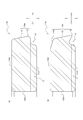
更に、図6~図11では、鋳鉄製又は樹脂製の第2リング17bを示しているが、図12に示すような鋼製の第2リング17bであってもよい。また、図12(b)の第2リング17bの外周面17b4は、軸方向Aの上側から、上側面17b2と連続する第1テーパ部18aと、この第1テーパ部18aの軸方向Aの下側に連続する第2テーパ部18bと、この第2テーパ部18bの軸方向Aの下側に位置する外周頂部19と、を備える。このように、軸方向Aに対して傾斜する角度が異なる複数のテーパ部を備える外周面17b4であってもよい。
(実施例)
以下、図1に示す内燃機関1の実施例としてのエンジンについて実施した確認実験の概要及び結果について説明する。ここで使用する実施例としてのエンジンは、シリンダ2(図1参照)の内径であるボア径が78[mm]であり、排気量が1.5[L]の直列4気筒の4サイクルガソリンエンジンである。このガソリンエンジンは、ターボ等の過給器を用いずに大気圧による自然吸気でシリンダ2内に吸気するものである。また、このガソリンエンジンは、各シリンダ2の吸気ポート12(図1参照)に燃料噴射する構成である。
以下、図1に示す内燃機関1の実施例としてのエンジンについて実施した確認実験の概要及び結果について説明する。ここで使用する実施例としてのエンジンは、シリンダ2(図1参照)の内径であるボア径が78[mm]であり、排気量が1.5[L]の直列4気筒の4サイクルガソリンエンジンである。このガソリンエンジンは、ターボ等の過給器を用いずに大気圧による自然吸気でシリンダ2内に吸気するものである。また、このガソリンエンジンは、各シリンダ2の吸気ポート12(図1参照)に燃料噴射する構成である。
このエンジンでは、第1リング17a(図2参照)、第2リング17b(図2参照)、第3リング17c(図2参照)が用いられている。第1リング17aとしては、リング幅(軸方向の長さ)が1.2[mm]、リング厚さ(径方向の長さ)が2.5[mm]、組み付け状態での合口隙間が0.20[mm]、張力が5[N]のものを用いている。
また、第2リング17bとしては、リング幅(軸方向の長さ)が1.0[mm]、リング厚さ(径方向の長さ)が2.5[mm]、張力が3[N]のものを用いている。第2リング17bの組み付け状態での合口隙間20(図6等参照)については、下側面17b1(図6等参照)での大きさS1に対して上側面17b2(図6等参照)での大きさS2を小さくしたものを、以下の7種類用意し、確認実験を行っている([表1]参照)。なお、軸方向の位置によらず合口隙間の大きさが一定の第2リングを含む比較例としてのエンジンについても、併せて確認実験を行っている([表1]参照)。また、第2リング17bの外周切欠き部22(図6等参照)の軸方向の長さは、0.25[mm]としている。比較例としてのエンジンは、実施例のエンジンに対して、第2リングの合口隙間のみが相違し、他の構成は同一である。

第3リング17cとしては、リング幅(軸方向の長さ)が2.0[mm]、組合せリング厚さ(径方向の長さ)が2.2[mm]、組み付け状態での合口隙間が0.30[mm]、張力が8[N]のものを用いている。
図13は、[表1]に示す11種類の第2リングそれぞれを含むエンジンに関して行った、高速高負荷運転時としての全負荷時(6000[rpm])のオイル消費量を測定する確認実験の結果を示す図である。図13では、比較例1のエンジンのオイル消費量を「1」としている。つまり、図13では、実施例1~7及び比較例2~4のオイル消費量を、比較例1のオイル消費量に対する比として示している。
図14は、[表1]に示す11種類の第2リングそれぞれを含むエンジンに関して行った、燃焼室が負圧となる加減速運転モード時のオイル消費量を測定する確認実験の結果を示す図である。
下側面17b1の合口隙間20の大きさS1を大きくすることにより、高速高負荷運転時の燃焼行程での燃焼室14(図1参照)の高圧ガスが、クランク室9(図1参照)側に抜け易くなる。より具体的に、第2リング17bが燃焼圧によって第2リング溝15b(図2等参照)の下面15b1(図2等参照)に押し付けられた状態で、第2ランド部31(図3等参照)側からの高圧ガスは、第2リング17bの上側面17b2(図3等参照)及び内周面17b3(図3等参照)に沿って進行し、合口隙間20のうち下側面17b1側の広い漸増領域E(図6等参照)を通過してクランク室9へと流れることができる。そのため、第2ランド圧の上昇によるガスの逆流が抑制でき、図13に示すように、オイル消費量の低減を実現できる。また、図13に示すように、上側面17b2の合口隙間20の大きさS2を、下側面17b1の合口隙間20の大きさS1よりも小さくすることで、オイル消費量を低減できる。これは、吸気行程において第3ランド部の位置から燃焼室側へとオイルが吸引されるオイルアップを抑制できるためと考えられる。このように、下側面17b1の合口隙間20の大きさS1を大きくし、かつ、上側面17b2の合口隙間20の大きさS2を下側面17b1の合口隙間20の大きさS1よりも小さくすることで、高速高負荷運転時のオイル消費を抑制できる。
図14に示すように、比較例1~4では、合口隙間が大きい構成ほど、オイル消費量が増大する。燃焼室が負圧となる加減速運転モードでは、オイルがクランク室9側から第3ランド部32、第2ランド部31を経由して、燃焼室14へとオイルが吸引される。そのため、合口隙間が大きい構成ほど、合口隙間を通じて吸引されるオイル量が増大し、オイル消費量が増大する。これに対して、図14に示す実施例1~7では、加減速運転モードにおいて、下側面17b1の合口隙間20の大きさS1を大きくしても、オイル消費量は増大しないことがわかる。これは、第2リング17bが負圧環境時に第2リング溝15bの上面15b2に押し付けられた状態で、オイルは、合口隙間20のうち上側面17b2の狭い隙間を通過しないと、燃焼室14側に移動できないためである。そのため、上側面17b2の合口隙間20の大きさS2を調整することにより、負圧環境時のオイル消費量を抑制できることがわかる。
以上のように、下側面17b1の合口隙間20の大きさS1を大きくすると共に、上側面17b2の合口隙間20の大きさS2を小さくすることで、高負荷運転時及び筒内負圧環境下においてオイル消費が増大することを抑制できる。
本発明に係るピストンリングは、上述の実施形態及び変形例に示す具体的な構成に限られるものではなく、請求の範囲の記載を逸脱しない限り、種々の変形・変更が可能である。例えば、本発明に係るピストリングを、4本のリング(トップリング、セカンドリング、サードリング、オイルリング)を有する内燃機関において、サードリングとして用いてもよい。つまり、サードリングについて上述の漸増領域Eを設ける構成としてもよい。
本発明はピストンリングに関し、特に、内燃機関、圧縮機関等に使用されるピストンリングに関する。
1:内燃機関
2:シリンダ
2a:シリンダの内壁
3:ピストン
4:ピストンピン
5:コネクティングロッド
6:クランクピン
7:クランクシャフト
8:クランクケース
9:クランク室
10:吸気バルブ
11:排気バルブ
12:吸気ポート
13:排気ポート
14:燃焼室
15:リング溝
15a:第1リング溝
15b:第2リング溝
15b1:第2リング溝の下面
15b2:第2リング溝の上面
15b3:第2リング溝の底面
15c:第3リング溝
16:ピストン本体
17:ピストンリング
17a:第1リング
17b:第2リング
17b1:第2リングの下側面
17b2:第2リングの上側面
17b3:第2リングの内周面
17b4:第2リングの外周面
17c:第3リング
18:テーパ部
18a:第1テーパ部
18b:第2テーパ部
19:外周頂部
20:合口隙間
21:合口部
22:外周切欠き部
23:欠損部
24、25:合口端面部
31:第2ランド部
32:第3ランド部
50:シリンダブロック
60:シリンダヘッド
120、220、320、420:合口隙間
121、221、321、421:合口部
124、125、224、225、324、325、424、425:合口端面部
326:曲面
A:ピストンの中心軸線方向(組み込み状態のピストンリングの軸方向)
B:ピストンリングの周方向
C:ピストンリングの径方向
E:合口隙間の漸増領域
O:ピストンの中心軸線
S1:下側面の合口隙間の大きさ
S2:上側面の合口隙間の大きさ
Claims (11)
- 軸方向に沿う断面視で、前記軸方向の上側から下側に向かうにつれて径方向の外側に拡がるテーパ部と、前記テーパ部に対して前記軸方向の下側で連続する外周頂部と、を備える外周面を備え、
合口隙間には、前記軸方向の下側に向かって下側面まで漸増する漸増領域が形成されており、
前記漸増領域は、前記外周面の前記外周頂部よりも前記軸方向の下側のみに設けられていることを特徴とするピストンリング。 - 前記外周面の前記外周頂部よりも前記軸方向の下側の位置に、前記合口隙間を除く周方向の全域に亘って外周切欠き部が形成されており、
前記漸増領域は、前記外周切欠き部が形成されている軸方向領域内に設けられていることを特徴とする、請求項1に記載のピストンリング。 - 前記漸増領域は、前記外周切欠き部が形成されている前記軸方向領域の全域に亘って設けられている、請求項2に記載のピストンリング。
- 前記外周切欠き部は、前記軸方向に沿う断面視で、ステップ状又はアンダカットステップ状に切欠かれて形成されていることを特徴とする、請求項2又は3に記載のピストンリング。
- 前記漸増領域を形成する少なくとも一方の合口端面部は、前記軸方向に対して傾斜する傾斜面により構成されていることを特徴とする、請求項1乃至4のいずれか1つに記載のピストンリング。
- 前記漸増領域を形成する両方の前記合口端面部は、前記傾斜面により構成されていることを特徴とする、請求項5に記載のピストンリング。
- 前記傾斜面は、凸形の曲面を含むことを特徴とする、請求項5又は6に記載のピストンリング。
- 前記傾斜面と前記下側面とは、凸形の曲面を介して連なっていることを特徴とする、請求項5乃至7のいずれか1つに記載のピストンリング。
- 前記傾斜面の前記軸方向に対する角度は、30度~80度であることを特徴とする、請求項5乃至8のいずれか1つに記載のピストンリング。
- 前記合口隙間の前記下側面での大きさは、前記合口隙間の上側面での大きさに対して、1.5~10倍であることを特徴とする、請求項1乃至9のいずれか1つに記載のピストンリング。
- 前記合口隙間は、前記漸増領域において、前記径方向の内側から外側に向かって漸増していることを特徴とする、請求項1乃至10のいずれか1つに記載のピストンリング。
Applications Claiming Priority (2)
| Application Number | Priority Date | Filing Date | Title |
|---|---|---|---|
| JP2018081414A JP2019190513A (ja) | 2018-04-20 | 2018-04-20 | ピストンリング |
| JP2018-081414 | 2018-04-20 |
Publications (1)
| Publication Number | Publication Date |
|---|---|
| WO2019203358A1 true WO2019203358A1 (ja) | 2019-10-24 |
Family
ID=68239672
Family Applications (1)
| Application Number | Title | Priority Date | Filing Date |
|---|---|---|---|
| PCT/JP2019/016881 WO2019203358A1 (ja) | 2018-04-20 | 2019-04-19 | ピストンリング |
Country Status (2)
| Country | Link |
|---|---|
| JP (1) | JP2019190513A (ja) |
| WO (1) | WO2019203358A1 (ja) |
Families Citing this family (1)
| Publication number | Priority date | Publication date | Assignee | Title |
|---|---|---|---|---|
| JP7478901B1 (ja) | 2023-01-31 | 2024-05-07 | 株式会社リケン | ピストンリング及びピストンリングの組合せ |
Citations (4)
| Publication number | Priority date | Publication date | Assignee | Title |
|---|---|---|---|---|
| JPH0259246U (ja) * | 1988-10-26 | 1990-04-27 | ||
| JPH0280261U (ja) * | 1988-12-08 | 1990-06-20 | ||
| WO2012118036A1 (ja) * | 2011-02-28 | 2012-09-07 | 日本ピストンリング株式会社 | ピストンリング |
| JP2016527460A (ja) * | 2013-08-07 | 2016-09-08 | フェデラル−モーグル コーポレイション | ピストンリング |
-
2018
- 2018-04-20 JP JP2018081414A patent/JP2019190513A/ja active Pending
-
2019
- 2019-04-19 WO PCT/JP2019/016881 patent/WO2019203358A1/ja active Application Filing
Patent Citations (4)
| Publication number | Priority date | Publication date | Assignee | Title |
|---|---|---|---|---|
| JPH0259246U (ja) * | 1988-10-26 | 1990-04-27 | ||
| JPH0280261U (ja) * | 1988-12-08 | 1990-06-20 | ||
| WO2012118036A1 (ja) * | 2011-02-28 | 2012-09-07 | 日本ピストンリング株式会社 | ピストンリング |
| JP2016527460A (ja) * | 2013-08-07 | 2016-09-08 | フェデラル−モーグル コーポレイション | ピストンリング |
Also Published As
| Publication number | Publication date |
|---|---|
| JP2019190513A (ja) | 2019-10-31 |
Similar Documents
| Publication | Publication Date | Title |
|---|---|---|
| EP2045488B1 (en) | Piston ring of reciprocating engine | |
| US20070272078A1 (en) | Piston Device for Internal Combustion Engine | |
| JP2006144700A (ja) | 内燃機関用エンジンのピストン及び内燃機関用エンジンのピストンとピストンリングの組合せ | |
| JP7297917B2 (ja) | シリンダライナ及びシリンダボア | |
| US10760524B2 (en) | Internal combustion engine | |
| US10927787B2 (en) | Piston for internal combustion engine | |
| WO2019203358A1 (ja) | ピストンリング | |
| JP2009281387A (ja) | 内燃機関用エンジンのピストン及び内燃機関用エンジンのピストンとピストンリングの組合せ | |
| JP6389865B2 (ja) | 内燃機関用ピストン | |
| US9194327B2 (en) | Cylinder liner with slots | |
| US10359112B2 (en) | Piston ring set for internal combustion engine and system and method thereof | |
| KR20190086204A (ko) | 내연기관용 피스톤 | |
| JP6467222B2 (ja) | 組合せオイルリング | |
| JP6528720B2 (ja) | ピストン | |
| JP6387237B2 (ja) | ピストンリング及び該ピストンリングを備えるエンジン | |
| JP2015129463A (ja) | 内燃機関のピストン | |
| WO2017130457A1 (ja) | 連接棒およびこれを備えたクロスヘッド型エンジン | |
| JP7308316B1 (ja) | ピストンリング | |
| JP2019116918A (ja) | 2ピースオイルリング用本体リング及びエンジン | |
| US20240159200A1 (en) | Internal combustion engine | |
| JPH0842693A (ja) | オイルリング | |
| JP2007040470A (ja) | ピストンリング及びピストン装置 | |
| JP2014009620A (ja) | 内燃機関用ピストンリング | |
| JP2001214805A (ja) | ピストン | |
| JP2006257887A (ja) | 内燃機関用ピストン |
Legal Events
| Date | Code | Title | Description |
|---|---|---|---|
| 121 | Ep: the epo has been informed by wipo that ep was designated in this application |
Ref document number: 19787862 Country of ref document: EP Kind code of ref document: A1 |
|
| NENP | Non-entry into the national phase |
Ref country code: DE |
|
| 122 | Ep: pct application non-entry in european phase |
Ref document number: 19787862 Country of ref document: EP Kind code of ref document: A1 |