WO2019198729A1 - Élément structural de véhicule automobile - Google Patents
Élément structural de véhicule automobile Download PDFInfo
- Publication number
- WO2019198729A1 WO2019198729A1 PCT/JP2019/015519 JP2019015519W WO2019198729A1 WO 2019198729 A1 WO2019198729 A1 WO 2019198729A1 JP 2019015519 W JP2019015519 W JP 2019015519W WO 2019198729 A1 WO2019198729 A1 WO 2019198729A1
- Authority
- WO
- WIPO (PCT)
- Prior art keywords
- frp
- joined
- structural member
- automobile structural
- hollow
- Prior art date
Links
Images


Classifications
-
- B—PERFORMING OPERATIONS; TRANSPORTING
- B62—LAND VEHICLES FOR TRAVELLING OTHERWISE THAN ON RAILS
- B62D—MOTOR VEHICLES; TRAILERS
- B62D29/00—Superstructures, understructures, or sub-units thereof, characterised by the material thereof
- B62D29/001—Superstructures, understructures, or sub-units thereof, characterised by the material thereof characterised by combining metal and synthetic material
- B62D29/005—Superstructures, understructures, or sub-units thereof, characterised by the material thereof characterised by combining metal and synthetic material preformed metal and synthetic material elements being joined together, e.g. by adhesives
-
- B—PERFORMING OPERATIONS; TRANSPORTING
- B62—LAND VEHICLES FOR TRAVELLING OTHERWISE THAN ON RAILS
- B62D—MOTOR VEHICLES; TRAILERS
- B62D21/00—Understructures, i.e. chassis frame on which a vehicle body may be mounted
- B62D21/15—Understructures, i.e. chassis frame on which a vehicle body may be mounted having impact absorbing means, e.g. a frame designed to permanently or temporarily change shape or dimension upon impact with another body
-
- B—PERFORMING OPERATIONS; TRANSPORTING
- B62—LAND VEHICLES FOR TRAVELLING OTHERWISE THAN ON RAILS
- B62D—MOTOR VEHICLES; TRAILERS
- B62D29/00—Superstructures, understructures, or sub-units thereof, characterised by the material thereof
- B62D29/04—Superstructures, understructures, or sub-units thereof, characterised by the material thereof predominantly of synthetic material
- B62D29/043—Superstructures
-
- B—PERFORMING OPERATIONS; TRANSPORTING
- B62—LAND VEHICLES FOR TRAVELLING OTHERWISE THAN ON RAILS
- B62D—MOTOR VEHICLES; TRAILERS
- B62D25/00—Superstructure or monocoque structure sub-units; Parts or details thereof not otherwise provided for
- B62D25/02—Side panels
- B62D25/025—Side sills thereof
-
- B—PERFORMING OPERATIONS; TRANSPORTING
- B62—LAND VEHICLES FOR TRAVELLING OTHERWISE THAN ON RAILS
- B62D—MOTOR VEHICLES; TRAILERS
- B62D25/00—Superstructure or monocoque structure sub-units; Parts or details thereof not otherwise provided for
- B62D25/04—Door pillars ; windshield pillars
-
- B—PERFORMING OPERATIONS; TRANSPORTING
- B62—LAND VEHICLES FOR TRAVELLING OTHERWISE THAN ON RAILS
- B62D—MOTOR VEHICLES; TRAILERS
- B62D25/00—Superstructure or monocoque structure sub-units; Parts or details thereof not otherwise provided for
- B62D25/08—Front or rear portions
-
- B—PERFORMING OPERATIONS; TRANSPORTING
- B62—LAND VEHICLES FOR TRAVELLING OTHERWISE THAN ON RAILS
- B62D—MOTOR VEHICLES; TRAILERS
- B62D25/00—Superstructure or monocoque structure sub-units; Parts or details thereof not otherwise provided for
- B62D25/20—Floors or bottom sub-units
-
- B—PERFORMING OPERATIONS; TRANSPORTING
- B62—LAND VEHICLES FOR TRAVELLING OTHERWISE THAN ON RAILS
- B62D—MOTOR VEHICLES; TRAILERS
- B62D29/00—Superstructures, understructures, or sub-units thereof, characterised by the material thereof
- B62D29/001—Superstructures, understructures, or sub-units thereof, characterised by the material thereof characterised by combining metal and synthetic material
Definitions
- the present invention relates to an automobile structural member.
- Automotive structural members are required to have impact resistance to protect passengers in the event of a collision.
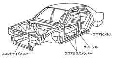
- the floor cross member as shown in FIG. 1 is required to have impact resistance at the time of side collision
- the floor tunnel and the side sill are required to have impact resistance at the time of frontal collision and rearward collision.
- the front side member is composed of a front side member front and a front side member rear, and the front side member rear is required to have impact resistance at the time of a frontal collision. In order to further improve the collision safety of automobiles, it is important to improve the impact resistance of each structural member.
- Patent Document 1 discloses a floor cross member composed of a hat-shaped member joined to the inside of a floor panel and a U-shaped member joined to the top of the hat-shaped member. It is disclosed.
- impact resistance is improved by dispersing and transmitting an impact load input at the time of a side collision of an automobile to a hat-shaped member and a U-shaped member.
- Patent Document 2 discloses a shock absorbing member having a composite structure in which an FRP member (high-strength lightweight material) is joined to an aluminum alloy hollow frame (shock absorbing material).
- the technique described in Patent Document 2 discloses a configuration in which almost 100% of the FRP members are joined in the longitudinal direction of the hollow frame, thereby achieving both an impact energy absorption function and a deformation prevention function.
- Patent Document 3 discloses a technique for bonding a CFRP reinforcing material to a wall portion of a metal hollow frame.
- the weight reduction and the load resistance are achieved by attaching the reinforcing material only to the place where the tensile load is concentrated.
- Patent Document 4 discloses a metal-CFRP composite member used for automobile members.
- the residual shear stress of the thermosetting adhesive for adhering the reinforcing material (CFRP) can be reduced.
- Patent Document 5 discloses a vehicle body manufacturing method in which a vehicle body member of an automobile is reinforced using a CFRP patch.
- the reinforcing effect can be enhanced by sticking or bolting the patch to the tensile surface of the stress concentration portion, and the magnitude of the reinforcing effect can be easily adjusted.
- Patent Document 2 discloses a configuration in which the FRP member is almost 100% joined in the longitudinal direction of the hollow frame, there is room for further contrivance at the joining location of the FRP member, and impact resistance and light weight. Further improvement in weight efficiency is required for achieving compatibility.
- Patent Document 3 describes that a reinforcing material is attached only to a place where a tensile load is concentrated. However, a configuration of a suitable reinforcing material with respect to impact resistance is not mentioned, and impact resistance is not described. In order to achieve both compatibility and weight reduction, further ingenuity is required.
- Patent Document 4 is a technique for reducing the residual shear stress of a thermosetting adhesive for adhering a reinforcing material (CFRP), and Patent Document 5 is a technique in which a patch is attached to a tensile surface of a stress concentration portion or Although it is a technique to reinforce by bolting, both of these documents do not fully refer to a suitable adhesion position of FRP member accompanying impact resistance and a technique for improving the weight efficiency. There is room for improvement.
- CFRP thermosetting adhesive for adhering a reinforcing material
- the present invention has been made in view of the above circumstances, and an object thereof is to improve the weight efficiency of impact resistance in automobile structural members.
- an automotive structural member comprising a hollow member having a flat surface portion and an FRP member joined to at least one location of the flat surface portion, wherein the FRP member is The hollow member is joined to at least a portion of the longitudinal length L of 0.1L to 0.9L, and the FRP member is joined to the flat portion at the portion of 0.1L to 0.9L.
- a FRP joint portion that is a portion where the FRP member is not joined, and a FRP non-joint portion that is a portion where the FRP member is not joined.
- the total width of the FRP joint portion is the total width of the planar portion. 8 to 60%
- the flexural rigidity of the FRP member at the FRP joint portion in the flat surface portion is 30 times or more of the flexural rigidity of the flat surface portion excluding the FRP member. Construction Wood is provided.
- the bending rigidity of the FRP member may be 100 times or more of the bending rigidity of the flat portion excluding the FRP member.
- the thickness of the FRP member may be 6 times or more the thickness of the planar portion.
- Each width D of the FRP non-joining part in the plane part may satisfy the following formula (1).
- t thickness of the plane part
- E Young's modulus of the plane part
- ⁇ y yield stress of the plane part
- the FRP member may be joined to the surface of the hollow member on the inner space side.
- the FRP member may be a CFRP member made of CFRP.
- the FRP member may be a GFRP member made of GFRP.
- 80% or more of the total fibers may be fibers in which the fiber direction of the CFRP member is within ⁇ 5 ° with respect to the longitudinal direction of the CFRP member.
- the automobile structural member may be at least one of a floor cross member, a floor tunnel, a front side member rear, and a side sill.
- the automobile structural member according to the present invention does not include a structural member in which the FRP member is bonded to the entire flat portion of the hollow member.
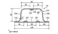
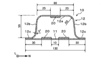
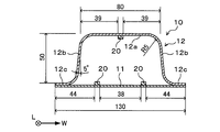
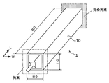
- FIG. 1 It is a figure which shows the vehicle body structure of a common motor vehicle. It is a perspective view showing a schematic structure of a structural member concerning an embodiment of the present invention. It is sectional drawing at the time of cut
- FIG. 1 It is sectional drawing which shows schematic structure of the structural member which concerns on another embodiment of this invention. It is a perspective view which shows the analysis model in a collision simulation (A). It is a figure which shows the joining position of the FRP member in a collision simulation (A). It is a figure which shows the joining position of the FRP member in a collision simulation (A). It is a figure which shows the joining position of the FRP member in a collision simulation (A). It is a figure which shows the joining position of the FRP member in a collision simulation (A). It is a perspective view which shows the analysis model in a collision simulation (B). It is a figure which shows the joining position of the FRP member in a collision simulation (B).
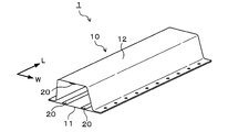
- the automobile structural member 1 (hereinafter also simply referred to as “structural member 1”) of the present embodiment includes a hollow member 10 and, for example, CFRP (carbon fiber reinforced resin) joined to the hollow member 10.
- FRP member 20 consisting of The resin and reinforcing fibers that constitute the FRP member 20 will be described later.
- both ends of the hollow member 10 in the longitudinal direction L are open, but the openings may be covered with another flat plate (not shown) or the like.
- the other flat plate is a wall portion of another member such as a side sill or a floor tunnel that is joined to an end portion of the floor cross member.
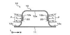
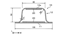
- the hollow member 10 includes a flat plate 11 and a member whose cross section perpendicular to the longitudinal direction L of the hollow member 10 is a hat shape (hereinafter referred to as “hat-shaped member 12”).
- hat-shaped member 12 a member whose cross section perpendicular to the longitudinal direction L of the hollow member 10 is a hat shape
- the raw material of the flat plate 11 and the hat-shaped member 12 is not specifically limited, For example, a steel plate or an aluminum plate is used.
- the longitudinal direction in which the closed section of the hollow member 10 in the plan view of the structural member 1 extends is referred to as the longitudinal direction L of the member, and the direction perpendicular to the longitudinal direction L in the plan view is referred to as the “width direction”. W ".
- the surface facing the hat-shaped member 12 that is, the surface on the inner space side of the hollow member 10 is referred to as “inner surface”, and the opposite surface is referred to as “outer surface”. Further, among the surfaces of the hat-shaped member 12, the surface on the inner space side of the hollow member 10 is referred to as an “inner surface”, and the opposite surface is referred to as an “outer surface”.
- the hat-shaped member 12 includes a top plate portion 12a, a vertical wall portion 12b extending from both ends of the top plate portion 12a in the width direction W and inclined with respect to the top plate portion 12a, and a vertical wall. It has a flange portion 12c extending outward in the width direction W from the tip portion of the portion 12b.
- the FRP member 20 of this embodiment is joined to two locations on the inner surface of the flat plate 11 and one location on the inner surface of the top plate portion 12 a of the hat-shaped member 12.
- the FRP members 20 bonded to the flat plate 11 are arranged at intervals, and the FRP members 20 bonded to the hat-shaped member 12 are bonded to the flat surface portion P of the top plate portion 12a.
- Each FRP member 20 extends along the longitudinal direction L of the hollow member 10. In this embodiment, each FRP member 20 continuously extends from one end to the other end in the longitudinal direction L of the hollow member 10.
- the length in the longitudinal direction L of the FRP member 20 may be 80% or more of the length L1 in the longitudinal direction L of the hollow member 10. Specifically, when the length of the hollow member 10 in the longitudinal direction L is L1, the FRP member 20 needs to be joined to at least a portion of 0.1L1 to 0.9L1 in the longitudinal direction L.
- the FRP member 20 be joined to a portion separated by a distance of 40% of the length L1 from the center in the length direction of the hollow member in the two end directions.
- both ends in the longitudinal direction of the hollow member 10 are normally connected to other members and are in a restrained state, and therefore the length in the longitudinal direction L of the hollow member 10 is set to both ends (0 to 0.1L1) in L1.
- 0.9L1 to 1.0L1) that is, impact resistance is ensured even if the FRP member 20 is not necessarily joined to the portion from both ends to 10% of the length L1.
- the longitudinal direction of the FRP member 20 is preferably in the range of ⁇ 10 ° to 10 ° (within ⁇ 10 °) with respect to the longitudinal direction L of the hollow member 10.
- the angle is more preferably within ⁇ 5 ° to + 5 ° (within ⁇ 5 °).
- the curved surface is contained in the edge part of the width direction W of the top-plate part 12a.
- the term “plane portion” of a member including a plane and a curved surface refers to the boundary between the plane and the curved surface, that is, the portion from the R stop of one curved surface to the R stop of the other curved surface. May be.
- the flat surface portion P of the vertical wall portion 12b of the hat-shaped member 12 is a portion from the R stop of the curved surface on the top plate portion 12a side to the R stop of the curved surface on the flange portion 12c side.
- r / t ⁇ 10000 is defined as plane portion when the plate thickness of a member (top plate portion 12a, vertical wall portion 12b, etc.) is t and the radius of curvature is r. P may be defined. Since the surface of the flat plate 11 is naturally the flat portion P, the FRP member 20 used in this embodiment is all provided on the inner surface of the flat portion P of the hollow member 10. In addition, as shown in the example mentioned later, the hollow member 10 does not have a curved surface part, and may be comprised only by the plane part.
- the joining method of the FRP member 20 with respect to the plane part P is not specifically limited, For example, it joins by affixing on the plane part P using a well-known adhesive agent.
- the structural member 1 is a state in which the FRP member 20 is attached to the inner surface of the flat surface portion P of the top plate portion 12a by an adhesive and the flat plate 11 in a state where the FRP member 20 is attached to the surface by an adhesive, for example.
- the hat-shaped member 12 is manufactured by joining the flange-shaped member 12 of the hat-shaped member 12 to each other by a known joining means such as spot welding.
- the manufacturing method of the structural member 1 is not limited to said method.
- the adhesive is between the flat surface portion P of the hollow member 10 and the FRP member 20. It can be confirmed that it exists. A specific example of a method for joining the flat portion P and the FRP member 20 will be described later.
- the automobile structural member 1 of the present embodiment is configured as described above. According to the structural member 1 of the present embodiment, since the FRP member 20 is joined to the flat surface portion P of the hollow member 10, the bending rigidity against the out-of-plane deformation in the flat surface portion P is increased, and an impact load is input. Occurrence of buckling phenomenon can be suppressed. Thereby, the impact resistance as the structural member 1 can be improved.
- FIG. 4 is a diagram in which the top plate portion 12a of the hat-shaped member 12 in the conventional structural member is compared to the support structure of the plate 30 and schematically shows a cross section of the surface including the width direction W of the structural member. is there.
- FIG. 5 is a diagram in which the top plate portion 12a of the hat-shaped member 12 in the structural member 1 of the present embodiment is compared to the support structure of the plate 30, and a cross section of the surface including the width direction W of the structural member 1 is schematically illustrated. It is shown. As shown in FIG.
- both ends of the plate 30 are in a simple support state by the support points 31 (corresponding to the vertical wall portion 12b of the hat-like member 12), but the central portion of the plate 30 is supported. It has not been. For this reason, the range of the so-called effective width b that becomes a part that affects the buckling strength is only in the vicinity of both ends of the plate 30.
- the “effective width b” in the present specification is an effective width calculated by the formula of von karman, and is referred to as a compression strength of a flat plate simply supported on both edges.
- the structural member 1 of the present embodiment since the FRP member 20 is joined to the center of the flat surface portion P of the top plate portion 12a, the bending rigidity of the portion increases, so the support of the plate 30 as shown in FIG.
- the structure is such that a new simple support point 32 is provided at the center of the plate 30. That is, both end portions and the central portion of the plate 30 are in a simple support state, and the range of the effective width b is increased as compared with the conventional structural member. As a result, the buckling strength is improved. Thereby, the impact resistance of the structural member 1 is improved.
- the increase in weight can be suppressed compared with the case where the hollow member 10 is reinforced using the reinforcement member which consists of conventional metal members, such as a steel plate, with respect to the structural member in which the FRP member 20 is not provided.
- the weight efficiency of impact resistance can be improved.
- FRP junction P A portion of FRP member 20 is bonded in the plane part P.
- the FRP junction P A is a concept including a planar portion P of the portion FRP member 20 is joined, and a FRP member 20 which is joined to the portion. Further, referred in the plane portion P portion FRP member 20 is not bonded, i.e., the portion other than FRP junction P A and "FRP unbonded portion P B".
- Parts FRP junction P A in order to be closer to a simply supported state as described above, except the bending rigidity of the FRP member 20 in the FRP junction P A, the FRP member 20 in the FRP junction P A, that ratio of the flexural rigidity of the flat portion P of the FRP junction P a (hereinafter, "flexural rigidity ratio") must be 30 or more. If the FRP member 20 having bending rigidity satisfying this condition is joined to the flat surface portion P of the hollow member 10, the impact resistance can be improved and the weight efficiency of the impact resistance can be improved. It can be equal to or more than a member in which 20 is not provided.
- the bending stiffness ratio is more preferably 50 or more, 80 or more, 100 or more, 150 or more, 200 or more, or 300 or more. Since the weight efficiency increases as the bending stiffness ratio increases, the upper limit of the bending stiffness is not particularly limited, and can be determined as appropriate depending on other factors such as the design conditions and cost of the structural member 1. Among several factors, in consideration of the adhesive strength of the FRP bending member, it is preferable to avoid excessively increasing the bending rigidity ratio, and specifically, it is preferable to set the bending rigidity ratio to 50000 or less. If necessary, the bending stiffness ratio may be 20000 or less, 10,000 or less, 5000 or less, 1000 or less, or 500 or less.
- the flexural rigidity of the FRP member 20 is the cross-sectional secondary moment I that can be calculated from the shape of the FRP member 20 in the vertical cross section of the hollow member 10 and the normal temperature of the FRP member 20 in the longitudinal direction L of the hollow member 10. It can be obtained as the product IE with the elastic modulus E obtained from the tensile test.
- the cross-sectional secondary moment I calculated from the shape of the FRP member 20 is parallel to the bonding surface of the hollow member 10 (the surface bonded to the flat surface portion P), and the centroid (center of gravity position) of the FRP member 20 is
- the following equation (2) is used in a coordinate system in which the straight line passing through is the origin, the direction perpendicular to the bonding surface is the y-axis, the length direction of the FRP member and the direction perpendicular to the y-axis direction is the x-axis.
- a in Formula (2) is a cross section.
- the cross-sectional shape of the FRP member 20 is preferably constant, but when the cross-sectional shape changes, the minimum value of the cross-sectional secondary moment is set as the cross-sectional secondary moment of the FRP member 20.
- the cross-sectional secondary moment I O of the plane portion P is based on a plane perpendicular to the thickness direction passing through the center of the thickness of the plane portion, and the direction perpendicular to the reference plane is the y axis, the longitudinal direction L of the hollow member 10 and Calculation is performed by the above equation (2) in a coordinate system in which the direction perpendicular to the y-axis direction is the x axis.
- the bending rigidity of the plane portion P is the product I O of the cross-sectional secondary moment I O of the plane portion P and the elastic modulus E O obtained from a tensile test at normal temperature in the longitudinal direction L of the plane portion P. It can be determined as EO .
- the bending stiffness ratio can be obtained as IE / I O E O.
- the said tensile test may be abbreviate
- the total width of the FRP junction P A is 8 to the total width of the flat portion P It needs to be 60%. If the sum of the width of the FRP junction P A is 60% of the overall width of the flat portion P, not lighter effect corresponding to the effect of improving the buckling strength can not be obtained. On the other hand, if the sum of the width of the FRP junction P A is less than 8% of the total width of the planar portion P, it is because there is a possibility that the effect of improving the buckling strength commensurate with the weight increase due to FRP member 20 can not be obtained .
- the interval between the adjacent simple support points 31 and 32 within the range of 0.5 to 1.6 times the effective width b. . That is, the width D of the FRP non-joining portion P B is von It is preferably within a range of 0.5 to 1.6 times the effective width b calculated by Karman's equation.
- the FRP member 20 is provided so that each width D of the FRP non-joining portion P B satisfies the following formula (1).
- impact resistance can be improved.
- the maximum value of the width D that satisfies the following formula (1) is more preferable.
- the lower limit of the width D may be 0.6 times, 0.7 times, or 0.8 times the effective width b, and the upper limit of the width D is relaxed to 2.5 times or 2.0 times. Alternatively, it may be 1.5 times, 1.4 times, 1.3 times, or 1.2 times.
- each width D of the FRP non-joined part P B is the adjacent FRP member 20. If there is, it is the interval in the width direction W between the adjacent FRP members 20, and if there is no adjacent FRP member 20, the FRP member 20 (however, closest to the end of the flat surface portion P of the bonding surface) It is also the distance in the width direction from the position) to the end of the plane portion P.
- the distance in the width direction W between adjacent FRP members 20 and the distance in the width direction from the FRP member 20 (however, the position closest to the end of the flat portion P of the bonding surface) to the end of the flat portion P are as follows. It is preferable to satisfy the above formula (1).
- the thickness of the FRP member 20 is preferably 6 times or more the thickness of the plane portion P to which the FRP member 20 is joined. It is good also as 4 times or more of the thickness of the plane part P, 8 times or more, or 10 times or more.
- the upper limit of the thickness of the FRP member 20 is not particularly required, but may be 15 times or less or 20 times or less the thickness of the plane portion P. As a result, the weight efficiency of impact resistance is increased, and the degree of improvement in impact resistance with respect to the increase in weight is increased.
- the upper limit of the thickness of the FRP member 20 is not particularly limited, but is determined according to the weight, cost, space at the joining location, and the like.
- the thickness of the FRP member is 6 of the thickness of the plane portion P to which the FRP is joined. If it is twice or more, the degree of improvement in impact resistance against an increase in weight can be reliably increased.
- the width of the FRP member 20 is appropriately changed depending on other factors such as the width of the plane portion P, the number of FRP members 20 joined to the plane portion P, the design conditions and cost of the structural member 1, For example, 5 to 15 mm.
- the FRP member 20 is joined to the flat surface portion P of the hollow member 10 to improve the weight efficiency of the impact resistance of the structural member 1.
- a structural member 1 is preferably used as a member at a location where an axial force acts during a collision among members constituting a vehicle body of an automobile.
- it is preferably used as a member of at least one of a floor cross member, a floor tunnel, a front side member rear, and a side sill.
- the structural member 1 as in the present embodiment does not need to separate the hollow member 10 and the FRP member 20 when the structural member 1 is reused as scrap, and is excellent in recyclability.
- the FRP member 20 is joined to two places in the inner surface of the flat plate 11 of the hollow member 10, and one place in the plane part P inner surface of the top-plate part 12a of the hat-shaped member 12, the FRP member 20 is joined.
- the number and the joining position are not particularly limited.
- the FRP member 20 may be joined to the vertical wall portion 12 b of the hat-shaped member 12.
- the FRP joint portion of the vertical wall portion 12b functions as a simple support point, whereby the weight efficiency of impact resistance can be improved.
- the FRP member 20 may be joined to the flat plate 11, the flat surface portion P of the top plate portion 12a, and the flat surface portion P of the vertical wall portion 12b.
- a plurality of FRP members 20 may not be provided. That is, the FRP member 20 may be joined so as to be along the longitudinal direction L of the hollow member 10 at least at one place on the flat surface portion P of the hollow member 10.
- the hollow member 10 includes the flat plate 11 and the hat-shaped member 12.
- the flat plate 11 may be a floor panel.
- the hollow member 10 is manufactured by joining the hat-shaped member 12 to the floor panel.
- the hollow member 10 may be composed of two hat-shaped members 12. That is, the configuration of the hollow member 10 is not particularly limited.
- the FRP member 20 is joined to the inner surface of the hollow member 10, but the FRP member 20 may be joined to the outer surface of the hollow member 10.
- the FRP member 20 is bonded to the inner surface of the hollow member 10 in order to improve the weight efficiency of impact resistance and to secure a vehicle interior space.
- the FRP member 20 since the FRP member 20 has higher strength related to tensile deformation than normal compression deformation, it is more effective to improve the weight efficiency of impact resistance when bonded to the inner surface side of the hollow member 10 that is relatively susceptible to tensile deformation. be able to.
- the FRP member 20 is made of, for example, CFRP (carbon fiber reinforced resin).
- CFRP carbon fiber reinforced resin
- the technology of the present invention can be applied to a configuration using the FRP member 20 made of various FRPs. That is, a GFRP member made of GFRP (glass fiber reinforced resin) may be used as the FRP member 20 as a member to be joined to the flat portion P of the hollow member 10.
- the member to be joined to the flat portion P of the hollow member 10 may be an FRP member made of FRP (fiber reinforced resin). From the viewpoint of weight reduction and specific rigidity improvement, it is important to use an FRP member, and a CFRP member is particularly preferable.
- the configuration of the FRP member and the joining method will be described.
- the FRP member that can be used as the reinforcing member means a fiber reinforced resin member that is composed of a matrix resin and a reinforced fiber material that is contained in the matrix resin and combined.
- the reinforcing fiber material for example, carbon fiber or glass fiber can be used.
- boron fiber, silicon carbide fiber, aramid fiber, or the like can be used as the reinforcing fiber material.
- examples of the reinforcing fiber base material used as the base material of the reinforcing fiber material include, for example, a nonwoven fabric base material using chopped fibers, a cloth material using continuous fibers, and a unidirectional reinforcing fiber base material (UD). Material) etc. can be used.
- UD unidirectional reinforcing fiber base material
- a unidirectional reinforced fiber base material (UD material) is used, and the fiber direction is in the range of ⁇ 5 ° to 5 ° in the longitudinal direction of the fiber reinforced resin member. It is more desirable to have them together.
- the CFRP member is an FRP member using carbon fiber as a reinforcing fiber material.
- the carbon fiber for example, a PAN-based or pitch-based one can be used.
- the strength with respect to weight can be improved efficiently.
- the volume fraction in the range of (carbon) fiber is -5 ° or more and 5 ° or less ( ⁇ 5 °) is 80% or more and 90% or more of the whole (carbon) fiber. Or it is preferable that it is 95% or more.
- the direction of the (carbon) fiber can be identified by observing the fiber reinforced resin member with a microfocus X-ray CT (X-ray computed tomography) system and computer-analyzing the obtained three-dimensional image.
- the ratio of the number of fibers becomes the volume fraction.
- the volume ratio can be calculated from the CFRP cross-sectional area calculated from the fiber diameter of CFRP and the fiber number ratio for each CFRP cross-sectional area.
- the GFRP member is an FRP member using glass fiber as a reinforcing fiber material. Although it is inferior to a carbon fiber in mechanical characteristics, it can suppress the electric corrosion of a metal member.
- thermosetting resin Both the thermosetting resin and the thermoplastic resin can be used as the matrix resin used for the FRP member.
- thermosetting resin include epoxy resins, unsaturated polyester resins, and vinyl ester resins.
- Thermoplastic resins include polyolefins (polyethylene, polypropylene, etc.) and acid-modified products thereof, polyamide resins such as nylon 6 and nylon 66, thermoplastic aromatic polyesters such as polyethylene terephthalate and polybutylene terephthalate, polycarbonate, polyethersulfone.
- polyphenylene ether and modified products thereof polyarylate, polyetherketone, polyetheretherketone, polyetherketoneketone, styrene resins such as vinyl chloride and polystyrene, and phenoxy resin.
- the matrix resin may be formed of a plurality of types of resin materials.
- thermoplastic resin As the matrix resin from the viewpoint of workability and productivity.
- the density of the reinforcing fiber material can be increased by using a phenoxy resin as the matrix resin.
- the phenoxy resin has a molecular structure very similar to that of an epoxy resin that is a thermosetting resin, the phenoxy resin has a heat resistance comparable to that of an epoxy resin.
- application to a high temperature environment is also possible by further adding a curing component.
- the addition amount may be appropriately determined in consideration of the impregnation property to the reinforcing fiber material, the brittleness of the FRP member, the tact time, the workability, and the like.
- the type of the adhesive resin composition that forms the adhesive resin layer is not particularly limited.
- the adhesive resin composition may be either a thermosetting resin or a thermoplastic resin.
- the kind of thermosetting resin and thermoplastic resin is not particularly limited.
- thermoplastic resins polyolefins and acid-modified products thereof, polystyrene, polymethyl methacrylate, AS resin, ABS resin, thermoplastic aromatic polyesters such as polyethylene terephthalate and polybutylene terephthalate, polycarbonate, polyimide, polyamide, polyamide
- a thermosetting resin 1 or more types chosen from an epoxy resin, a vinyl ester resin, a phenol resin, and a urethane resin can be used, for example
- the adhesive resin composition can be appropriately selected according to the characteristics of the matrix resin constituting the FRP member, the characteristics of the reinforcing member, or the characteristics of the metal member.
- the adhesiveness is improved by using a resin having a polar functional group or a resin subjected to acid modification as the adhesive resin layer.
- the adhesion between the FRP member and the metal member can be improved by adhering the FRP member to the metal member using the above-described adhesive resin layer. If it does so, the deformation
- the form of the adhesive resin composition used to form the adhesive resin layer can be, for example, a liquid such as powder or varnish, or a solid such as a film.
- a crosslinkable adhesive resin composition may be formed by blending a crosslinkable curable resin and a crosslinker into the adhesive resin composition.
- a crosslinkable curable resin for example, a bifunctional or higher functional epoxy resin or a crystalline epoxy resin can be used.
- an amine, an acid anhydride, etc. can be used as a crosslinking agent.
- various additives such as various rubber
- the compounding of the FRP member into the metal member can be realized by various methods. For example, it can be obtained by adhering an FRP forming prepreg which is an FRP member or an FRP molding prepreg thereof and a metal member with the above-described adhesive resin composition, and solidifying (or curing) the adhesive resin composition. .
- the FRP member and the metal member can be combined by performing thermocompression bonding.
- the above-mentioned adhesion of FRP or FRP molding prepreg to a metal member can be performed before molding, during molding, or after molding.
- FRP or FRP molding prepreg may be bonded to the metal member.
- the workpiece to which the FRP member is bonded may be molded to obtain a composite metal member.
- the matrix resin of the FRP member is a thermoplastic resin, it is possible to perform a bending process or the like on the portion to which the FRP member is bonded.
- composite batch molding in which the thermocompression bonding step and the molding step are integrated may be performed.
- the joining method of the FRP member and the metal member is not limited to the above-described adhesion by the adhesive resin layer.
- the FRP member and the metal member may be mechanically joined. More specifically, a fastening hole is formed at a position corresponding to each of the FRP member and the metal member, and these are fastened through the hole by a fastening means such as a bolt or a rivet.
- the member may be joined.
- the FRP member and the metal member may be joined by a known joining means.
- the FRP member and the metal member may be joined in a composite manner by a plurality of joining means.
- the adhesion by the adhesive resin layer and the fastening by the fastening means may be used in combination.
- the metal member according to the present invention may be plated. Thereby, corrosion resistance improves. In particular, it is more suitable when the metal member is a steel material.
- the type of plating is not particularly limited, and known plating can be used. For example, as galvanized steel sheets (steel materials), hot dip galvanized steel sheets, galvannealed steel sheets, Zn—Al—Mg alloy plated steel sheets, aluminum plated steel sheets, electrogalvanized steel sheets, electric Zn—Ni alloy plated steel sheets, etc. Can be used.
- the metal member may have a surface coated with a film called chemical conversion treatment.
- chemical conversion treatment a generally known chemical conversion treatment can be used.
- the chemical conversion treatment zinc phosphate treatment, chromate treatment, chromate-free treatment or the like can be used.
- the film may be a known resin film.
- the metal member may be one that is generally painted. Thereby, corrosion resistance improves more.
- a known resin can be used.
- an epoxy resin, a urethane resin, an acrylic resin, a polyester resin, or a fluorine resin can be used as a main resin.
- generally well-known pigment may be added to the coating as needed.
- the coating may be a clear coating to which no pigment is added. Such coating may be applied to the metal member in advance before the FRP member is combined, or may be applied to the metal member after the FRP member is combined. Alternatively, the FRP member may be combined after the metal member has been painted in advance, and then painted.
- the paint used for painting may be a solvent-based paint, a water-based paint, a powder paint, or the like.
- a known method can be applied as a method of painting.
- electrodeposition coating, spray coating, electrostatic coating, immersion coating, or the like can be used as a coating method. Since electrodeposition coating is suitable for coating the end face and gap portion of a metal member, it is excellent in corrosion resistance after coating. Moreover, coating film adhesion improves by performing generally well-known chemical conversion treatments, such as a zinc phosphate process and a zirconia process, on the surface of a metal member before coating.
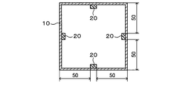
- the structural member 1 of the analysis model is composed of a hollow member 10 composed of a flat plate 11 and a hat-shaped member 12, and an FRP member 20 composed of CFRP.
- the flat plate 11 and the hat-shaped member 12 are spot-welded at the flange portion 12c of the hat-shaped member 12, and the interval between spot spots is 40 mm.
- the plate thickness of the flat plate 11 and the hat-shaped member 12 is 1.0 mm, and the yield stress is 700 MPa.
- the FRP member 20 is joined to two locations on the inner surface of the flat plate 11 and one location on the inner surface of the flat portion of the top plate portion 12 a of the hat-shaped member 12.
- the ends in the width direction W of the two FRP members 20 joined to the inner surface of the flat plate 11 are 40 mm from the ends in the width direction W of the flat plate 11, respectively, and the distance between the FRP members 20 is 30 mm.
- An end portion in the width direction W of the FRP member 20 joined to the top plate portion 12a is located at a position of 35 mm from the pair of opposing vertical wall portions 12b.
- the FRP member 20 is continuously joined from one end to the other end in the longitudinal direction L of the hollow member 10.
- one end face of the analysis model is completely restrained, and the other end face is restrained from causing in-plane deformation while allowing displacement of the hollow member 10 in the longitudinal direction L. .
- the end surface on the side that is completely constrained is referred to as a complete constraining side end surface, and the opposite end surface is referred to as a non-fully constraining side end surface.
- the collision simulation (A) was carried out under such a constraint condition that the end surface on the incomplete constraint side was compressed by 10 mm in the longitudinal direction of the hollow member 10.
- the collision speed at this time was 3 m / s, the element size was 1 mm, and the collision analysis was performed by the nonlinear structural analysis software LS-DYNA.
- the collision simulation (A) was performed with a plurality of analysis models having different thicknesses of the FRP member 20.
- the thickness of each FRP member 20 used for one analysis model is equal to each other.
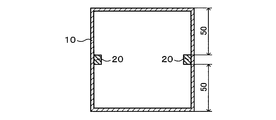
- an analysis model (Comparative Example 1) in which the FRP member 20 is not provided for the structural member 1 shown in FIG. 9, the entire inner surface of the flat plate 11 as shown in FIG. 10, and the top plate portion 12a.
- An analysis model (Comparative Example 2) in which the FRP member 20 was bonded to the entire inner surface of the flat part was created, and a collision simulation (A) was performed with each analysis model.
- FIG. 1 an analysis model in which the FRP member 20 is not provided for the structural member 1 shown in FIG. 9, the entire inner surface of the flat plate 11 as shown in FIG. 10, and the top plate portion 12a.
- An analysis model (Comparative Example 2) in which the FRP member 20 was bonded to the entire inner surface of the flat part was created, and a collision simulation (A) was performed with each analysis model.
- the width of the FRP member is 10 mm, but the widths of the FRP members of Example 7 and Comparative Example 4 are 30 mm and 2 mm, respectively, as shown in FIGS. 11 and 12 (Table 1). reference).
- the full width 130 mm of the plane part P of Example 7 and Comparative Example 4 is the same as that in FIG. 9, and the sticking center position of the FRP member in FIG. 9 is the same.
- fibers whose FRP member fiber direction is within ⁇ 5 ° (within a range of ⁇ 5 ° to + 5 °) of the longitudinal direction of the FRP member are It was 80% or more.
- the results of the collision simulation (A) are shown in Table 1 below.
- the maximum reaction force that occurs when the end face on the incomplete restraint side is compressed was measured. Since the maximum reaction force is correlated with the buckling strength, it is an index for evaluating impact resistance. Further, the maximum reaction force / weight was calculated as an index for evaluating the weight efficiency of impact resistance, and the ratio of the weight efficiency in each example to the weight efficiency of Comparative Example 1 in which no FRP member was provided was calculated. Moreover, the bending rigidity of the FRP member single body in the FRP joint part in any one place of a structural member and the bending rigidity of the plane part P in a FRP joint part were each calculated, and ratio (bending rigidity ratio) of both was computed.
- the value of the "total width of the FRP junction P A / planar portion P overall width ⁇ 100" and the "PA-width / flat portion width” (unit:%) is defined as, the example, in Comparative Example This value was calculated in each part where the FRP joint part such as the flat plate 11 and the top plate part 12a and the FRP non-joint part coexist. Further, in view of the condition of the formula (1) described in the above embodiment, the value ⁇ shown in the following formula (3) is defined, and in each part such as the flat plate 11 and the top plate portion 12a in each example and comparative example. This value ⁇ (unit:%) was calculated. In addition, in the case of FIG. 9 with the value of ⁇ in Table 1, the values at the top plate portion 12a and the values at three locations of the flat plate 11 are shown.
- Comparative Example 2 which is a structural member in which the FRP member 20 is joined to the entire flat portion of the hollow member 10 improves the bending rigidity but does not include the FRP member 20. Weight efficiency is lower than structural members. The reason for such a result is that there is no portion functioning like a simple support point in the central portion of the plane portion. More specifically, when the FRP member 20 is joined to the entire flat surface portion, the end portion in the width direction of the FRP joint portion approaches a simple support state, but the central portion in the width direction of the flat surface portion is in a simple support state. It is still a part that does not contribute to buckling strength. For this reason, the impact resistance corresponding to the increase in weight cannot be obtained.
- Examples 1 to 7 have higher weight efficiency than Comparative Example 1. Considering the result of this simulation, the weight efficiency can be improved when the bending stiffness ratio is 30 or more. In particular, when the FRP member 20 having a thickness of 6 times or more the plate thickness (1.0 mm) of the flat plate or hat-shaped member is joined, the weight efficiency is remarkably increased.
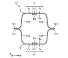
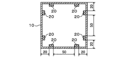
- the structural member 1 of the analysis model is composed of a square tube which is a hollow member 10, and an FRP member made of CFRP is joined to the inner surface of the square tube.
- the plate thickness of the square tube is 1.0 mm, and the yield stress is 700 MPa.
- one end surface of the analysis model is a completely constrained side end surface, and the other end surface is an incompletely constrained side end surface.
- the collision simulation (B) was performed under such a constraint condition that the end surface on the incomplete constraint side was compressed 20 mm in the longitudinal direction of the hollow member 10.
- the collision speed at this time was 3 m / s, the element size was 1 mm, and the collision analysis was performed by the nonlinear structural analysis software LS-DYNA.
- the collision simulation (B) was performed with a plurality of analysis models in which the joining positions of the FRP member 20 are different as shown in FIGS.
- the thickness of each FRP member 20 used for one analysis model is equal to each other.
- an analysis model (Comparative Example 5) in which the FRP member 20 is not provided in the structural member shown in FIG. 14 is created and a collision simulation (B) is performed.
- the structural member shown in FIG. An analysis model was created and a collision simulation (B) was performed.
- the fibers in which the directions of the fibers of the FRP members of Examples 9 and 10 are within ⁇ 5 ° of the longitudinal direction of the FRP members are 80% of the total fibers in volume fraction, and Comparative Examples 5 and 6, Example 8, The fibers in which the direction of the fibers of the 11 to 13 FRP members was within ⁇ 5 ° of the longitudinal direction of the FRP member was 100% of the total fiber in terms of volume fraction.
- the structural members of Examples 8 to 13 to which the FRP member 20 is joined are greatly improved in weight efficiency compared to the structural member of Comparative Example 5 in which the FRP member 20 is not provided. Yes.
- the weight efficiency can be improved by providing each FRP member 20 on a plane portion facing each other. Can be improved.
- the weight efficiency can be improved by increasing the number of FRP members 20 provided in the same plane portion. This is because the number of locations approaching the simple support state increases in the same plane portion, and the range of the effective width increases.
- Example 9 When comparing Example 9 and Example 12, although the number of FRP members 20 is the same, the weight efficiency of impact resistance is higher in Example 9. The reason why such a difference occurs is that the distance between the adjacent FRP members 20 at the central portion of the plane portion is narrower in the ninth embodiment, and the effect of the effective width is not at the FRP non-intensity in the central portion of the plane portion. It is easy to reach the joint portion, and the FRP non-joint portion is in a state of effectively contributing to the improvement of the buckling strength. Therefore, it is preferable that the FRP member 20 is provided so that the length of the FRP non-joining portion of the plane portion is equal to or less than the effective width.
- the present invention can be used for a floor cross member of an automobile, for example.
Abstract
Afin d'améliorer l'efficacité de poids résistant aux chocs dans un élément structural de véhicule automobile, l'élément structural de véhicule automobile selon l'invention comprend : un élément creux présentant une section plate ; et un élément FRP assemblé à au moins un emplacement sur la section plate. L'élément structural de véhicule automobile est caractérisé en ce que : l'élément FRP est assemblé à au moins une section 0,1L1-0,9L1 de la longueur L1 dans la direction longitudinale de l'élément creux ; une section assemblée FRP est une section à laquelle l'élément FRP est assemblé et une section non assemblée FRP est une section à laquelle l'élément FRP n'est pas assemblé formée au niveau du site 0,1L1-0,9L1 dans la section plate ; la largeur totale de la section assemblée FRP dans la section plate est de 8 %-60 % de la largeur totale de la section plate ; et la rigidité à la flexion de l'élément FRP dans la section d'assemblage FRP dans la section plate est d'au moins 30 fois la rigidité à la flexion de la section plate à l'exclusion de l'élément FRP.
Priority Applications (4)
| Application Number | Priority Date | Filing Date | Title |
|---|---|---|---|
| JP2020513416A JP6969674B2 (ja) | 2018-04-09 | 2019-04-09 | 自動車構造部材 |
| US17/044,716 US11541933B2 (en) | 2018-04-09 | 2019-04-09 | Automotive structural member |
| EP19784480.6A EP3760519B1 (fr) | 2018-04-09 | 2019-04-09 | Élément structural de véhicule automobile |
| CN201980023629.9A CN111989257B (zh) | 2018-04-09 | 2019-04-09 | 汽车构造构件 |
Applications Claiming Priority (2)
| Application Number | Priority Date | Filing Date | Title |
|---|---|---|---|
| JP2018-074647 | 2018-04-09 | ||
| JP2018074647 | 2018-04-09 |
Publications (1)
| Publication Number | Publication Date |
|---|---|
| WO2019198729A1 true WO2019198729A1 (fr) | 2019-10-17 |
Family
ID=68164189
Family Applications (1)
| Application Number | Title | Priority Date | Filing Date |
|---|---|---|---|
| PCT/JP2019/015519 WO2019198729A1 (fr) | 2018-04-09 | 2019-04-09 | Élément structural de véhicule automobile |
Country Status (5)
| Country | Link |
|---|---|
| US (1) | US11541933B2 (fr) |
| EP (1) | EP3760519B1 (fr) |
| JP (1) | JP6969674B2 (fr) |
| CN (1) | CN111989257B (fr) |
| WO (1) | WO2019198729A1 (fr) |
Families Citing this family (2)
| Publication number | Priority date | Publication date | Assignee | Title |
|---|---|---|---|---|
| DE102017121975A1 (de) * | 2017-09-22 | 2019-03-28 | GEDIA Gebrüder Dingerkus GmbH | Verfahren zur Herstellung von Bauteilen aus Metallblech |
| WO2019198729A1 (fr) * | 2018-04-09 | 2019-10-17 | 日本製鉄株式会社 | Élément structural de véhicule automobile |
Citations (7)
| Publication number | Priority date | Publication date | Assignee | Title |
|---|---|---|---|---|
| JPH06101732A (ja) | 1992-09-17 | 1994-04-12 | Kobe Steel Ltd | 複合構造の衝撃吸収用部材 |
| JP2013212730A (ja) * | 2012-03-30 | 2013-10-17 | Fuji Heavy Ind Ltd | 車両 |
| JP2014233999A (ja) | 2013-05-31 | 2014-12-15 | 本田技研工業株式会社 | 自動車の車体製造方法 |
| JP2015112898A (ja) | 2013-12-09 | 2015-06-22 | トヨタ自動車株式会社 | 車両下部構造 |
| JP2015160524A (ja) | 2014-02-27 | 2015-09-07 | 本田技研工業株式会社 | 自動車の車体構造 |
| JP2017061068A (ja) | 2015-09-24 | 2017-03-30 | 本田技研工業株式会社 | 金属−cfrp複合部材 |
| JP2018034664A (ja) * | 2016-08-31 | 2018-03-08 | トヨタ自動車株式会社 | 車両用骨格構造 |
Family Cites Families (22)
| Publication number | Priority date | Publication date | Assignee | Title |
|---|---|---|---|---|
| JP3498614B2 (ja) * | 1999-01-29 | 2004-02-16 | マツダ株式会社 | 車両の車体構造 |
| JP2007176328A (ja) * | 2005-12-28 | 2007-07-12 | Toray Ind Inc | Frp構造体 |
| DE102012000458A1 (de) * | 2012-01-13 | 2012-09-06 | Daimler Ag | Trägerteil |
| JP5983583B2 (ja) * | 2013-11-01 | 2016-08-31 | トヨタ自動車株式会社 | 車両の骨格構造 |
| DE102013018631A1 (de) * | 2013-11-06 | 2014-05-08 | Daimler Ag | Hohlkörper-Strukturteil, Herstellverfahren und Kraftfahrzeugkarosserie |
| WO2015157250A1 (fr) * | 2014-04-09 | 2015-10-15 | Honda Motor Co., Ltd. | Construction de châssis de véhicule et procédé associé |
| JP6109271B2 (ja) * | 2015-02-06 | 2017-04-05 | 株式会社神戸製鋼所 | 接合構造体、及び接合構造体の製造方法 |
| RU2696505C1 (ru) * | 2016-02-19 | 2019-08-02 | Ниппон Стил Корпорейшн | Автомобильный элемент |
| WO2018078990A1 (fr) * | 2016-10-24 | 2018-05-03 | 本田技研工業株式会社 | Panneau de plancher de véhicule et procédé de fabrication de panneau de plancher de véhicule |
| MX2020002130A (es) * | 2017-09-01 | 2020-07-14 | Nippon Steel Corp | Miembro hueco. |
| CN111051187B (zh) * | 2017-09-01 | 2022-06-07 | 日本制铁株式会社 | 中空的部件 |
| EP3486144B1 (fr) * | 2017-11-15 | 2022-01-19 | Sika Technology Ag | Système d'un élément structural renforcé d'un véhicule automobile |
| DE102017222652A1 (de) * | 2017-12-13 | 2019-06-13 | Bayerische Motoren Werke Aktiengesellschaft | Faserverstärkte Fahrzeugkarosserie |
| US11060543B2 (en) * | 2017-12-28 | 2021-07-13 | Honda Motor Co., Ltd. | Device and method of applying a sealant around a structural adhesive to prevent corrosion |
| JP6981322B2 (ja) * | 2018-03-19 | 2021-12-15 | トヨタ自動車株式会社 | 車両骨格構造 |
| WO2019198729A1 (fr) * | 2018-04-09 | 2019-10-17 | 日本製鉄株式会社 | Élément structural de véhicule automobile |
| JP2019209767A (ja) * | 2018-06-01 | 2019-12-12 | 本田技研工業株式会社 | 車両用構造体 |
| WO2020017662A1 (fr) * | 2018-07-20 | 2020-01-23 | 日本製鉄株式会社 | Élément structural de véhicule |
| JP6933203B2 (ja) * | 2018-12-20 | 2021-09-08 | Jfeスチール株式会社 | 自動車用衝突エネルギー吸収部品、該自動車用衝突エネルギー吸収部品の製造方法 |
| JP6950871B2 (ja) * | 2019-01-23 | 2021-10-13 | Jfeスチール株式会社 | 車体骨格部品 |
| EP3929037A4 (fr) * | 2019-02-22 | 2022-01-12 | JFE Steel Corporation | Composant d'absorption d'énergie de collision pour automobiles |
| JP7120175B2 (ja) * | 2019-07-18 | 2022-08-17 | Jfeスチール株式会社 | 自動車用衝突エネルギー吸収部品、該自動車用衝突エネルギー吸収部品の製造方法 |
-
2019
- 2019-04-09 WO PCT/JP2019/015519 patent/WO2019198729A1/fr unknown
- 2019-04-09 US US17/044,716 patent/US11541933B2/en active Active
- 2019-04-09 JP JP2020513416A patent/JP6969674B2/ja active Active
- 2019-04-09 CN CN201980023629.9A patent/CN111989257B/zh active Active
- 2019-04-09 EP EP19784480.6A patent/EP3760519B1/fr active Active
Patent Citations (7)
| Publication number | Priority date | Publication date | Assignee | Title |
|---|---|---|---|---|
| JPH06101732A (ja) | 1992-09-17 | 1994-04-12 | Kobe Steel Ltd | 複合構造の衝撃吸収用部材 |
| JP2013212730A (ja) * | 2012-03-30 | 2013-10-17 | Fuji Heavy Ind Ltd | 車両 |
| JP2014233999A (ja) | 2013-05-31 | 2014-12-15 | 本田技研工業株式会社 | 自動車の車体製造方法 |
| JP2015112898A (ja) | 2013-12-09 | 2015-06-22 | トヨタ自動車株式会社 | 車両下部構造 |
| JP2015160524A (ja) | 2014-02-27 | 2015-09-07 | 本田技研工業株式会社 | 自動車の車体構造 |
| JP2017061068A (ja) | 2015-09-24 | 2017-03-30 | 本田技研工業株式会社 | 金属−cfrp複合部材 |
| JP2018034664A (ja) * | 2016-08-31 | 2018-03-08 | トヨタ自動車株式会社 | 車両用骨格構造 |
Non-Patent Citations (1)
| Title |
|---|
| See also references of EP3760519A4 |
Also Published As
| Publication number | Publication date |
|---|---|
| CN111989257B (zh) | 2022-12-30 |
| EP3760519B1 (fr) | 2024-03-06 |
| JPWO2019198729A1 (ja) | 2021-01-14 |
| EP3760519A4 (fr) | 2021-12-01 |
| JP6969674B2 (ja) | 2021-11-24 |
| US11541933B2 (en) | 2023-01-03 |
| CN111989257A (zh) | 2020-11-24 |
| EP3760519A1 (fr) | 2021-01-06 |
| US20210031835A1 (en) | 2021-02-04 |
Similar Documents
| Publication | Publication Date | Title |
|---|---|---|
| JP6801825B2 (ja) | 車両用構造部材 | |
| WO2019198729A1 (fr) | Élément structural de véhicule automobile | |
| US11945205B2 (en) | Curved panel part | |
| JP6969673B2 (ja) | T字継手構造 | |
| JP6693605B1 (ja) | 車両用構造部材 | |
| JP7389378B2 (ja) | 自動車のフラットパネル構造 | |
| US11731392B2 (en) | Panel structure | |
| JP2019182168A (ja) | センターピラーインナーおよびセンターピラー | |
| JP6617859B1 (ja) | 車両用構造部材 | |
| JP7035742B2 (ja) | 車両用構造部材 | |
| WO2020017647A1 (fr) | Élément structurel de véhicule | |
| JP6683293B2 (ja) | 自動車のt字継手構造 | |
| JP7087768B2 (ja) | 車両用構造部材 | |
| JP7107055B2 (ja) | 車両用構造部材 | |
| JP6708323B1 (ja) | センターピラーインナーおよびセンターピラー | |
| JP2019209660A (ja) | 曲面パネル部材 |
Legal Events
| Date | Code | Title | Description |
|---|---|---|---|
| 121 | Ep: the epo has been informed by wipo that ep was designated in this application |
Ref document number: 19784480 Country of ref document: EP Kind code of ref document: A1 |
|
| ENP | Entry into the national phase |
Ref document number: 2020513416 Country of ref document: JP Kind code of ref document: A |
|
| ENP | Entry into the national phase |
Ref document number: 2019784480 Country of ref document: EP Effective date: 20201001 |
|
| NENP | Non-entry into the national phase |
Ref country code: DE |