WO2019198729A1 - Automobile structural member - Google Patents
Automobile structural member Download PDFInfo
- Publication number
- WO2019198729A1 WO2019198729A1 PCT/JP2019/015519 JP2019015519W WO2019198729A1 WO 2019198729 A1 WO2019198729 A1 WO 2019198729A1 JP 2019015519 W JP2019015519 W JP 2019015519W WO 2019198729 A1 WO2019198729 A1 WO 2019198729A1
- Authority
- WO
- WIPO (PCT)
- Prior art keywords
- frp
- joined
- structural member
- automobile structural
- hollow
- Prior art date
Links
Images


Classifications
-
- B—PERFORMING OPERATIONS; TRANSPORTING
- B62—LAND VEHICLES FOR TRAVELLING OTHERWISE THAN ON RAILS
- B62D—MOTOR VEHICLES; TRAILERS
- B62D29/00—Superstructures, understructures, or sub-units thereof, characterised by the material thereof
- B62D29/001—Superstructures, understructures, or sub-units thereof, characterised by the material thereof characterised by combining metal and synthetic material
- B62D29/005—Superstructures, understructures, or sub-units thereof, characterised by the material thereof characterised by combining metal and synthetic material preformed metal and synthetic material elements being joined together, e.g. by adhesives
-
- B—PERFORMING OPERATIONS; TRANSPORTING
- B62—LAND VEHICLES FOR TRAVELLING OTHERWISE THAN ON RAILS
- B62D—MOTOR VEHICLES; TRAILERS
- B62D21/00—Understructures, i.e. chassis frame on which a vehicle body may be mounted
- B62D21/15—Understructures, i.e. chassis frame on which a vehicle body may be mounted having impact absorbing means, e.g. a frame designed to permanently or temporarily change shape or dimension upon impact with another body
-
- B—PERFORMING OPERATIONS; TRANSPORTING
- B62—LAND VEHICLES FOR TRAVELLING OTHERWISE THAN ON RAILS
- B62D—MOTOR VEHICLES; TRAILERS
- B62D29/00—Superstructures, understructures, or sub-units thereof, characterised by the material thereof
- B62D29/04—Superstructures, understructures, or sub-units thereof, characterised by the material thereof predominantly of synthetic material
- B62D29/043—Superstructures
-
- B—PERFORMING OPERATIONS; TRANSPORTING
- B62—LAND VEHICLES FOR TRAVELLING OTHERWISE THAN ON RAILS
- B62D—MOTOR VEHICLES; TRAILERS
- B62D25/00—Superstructure or monocoque structure sub-units; Parts or details thereof not otherwise provided for
- B62D25/02—Side panels
- B62D25/025—Side sills thereof
-
- B—PERFORMING OPERATIONS; TRANSPORTING
- B62—LAND VEHICLES FOR TRAVELLING OTHERWISE THAN ON RAILS
- B62D—MOTOR VEHICLES; TRAILERS
- B62D25/00—Superstructure or monocoque structure sub-units; Parts or details thereof not otherwise provided for
- B62D25/04—Door pillars ; windshield pillars
-
- B—PERFORMING OPERATIONS; TRANSPORTING
- B62—LAND VEHICLES FOR TRAVELLING OTHERWISE THAN ON RAILS
- B62D—MOTOR VEHICLES; TRAILERS
- B62D25/00—Superstructure or monocoque structure sub-units; Parts or details thereof not otherwise provided for
- B62D25/08—Front or rear portions
-
- B—PERFORMING OPERATIONS; TRANSPORTING
- B62—LAND VEHICLES FOR TRAVELLING OTHERWISE THAN ON RAILS
- B62D—MOTOR VEHICLES; TRAILERS
- B62D25/00—Superstructure or monocoque structure sub-units; Parts or details thereof not otherwise provided for
- B62D25/20—Floors or bottom sub-units
-
- B—PERFORMING OPERATIONS; TRANSPORTING
- B62—LAND VEHICLES FOR TRAVELLING OTHERWISE THAN ON RAILS
- B62D—MOTOR VEHICLES; TRAILERS
- B62D29/00—Superstructures, understructures, or sub-units thereof, characterised by the material thereof
- B62D29/001—Superstructures, understructures, or sub-units thereof, characterised by the material thereof characterised by combining metal and synthetic material
Definitions
- the present invention relates to an automobile structural member.
- Automotive structural members are required to have impact resistance to protect passengers in the event of a collision.
- the floor cross member as shown in FIG. 1 is required to have impact resistance at the time of side collision
- the floor tunnel and the side sill are required to have impact resistance at the time of frontal collision and rearward collision.
- the front side member is composed of a front side member front and a front side member rear, and the front side member rear is required to have impact resistance at the time of a frontal collision. In order to further improve the collision safety of automobiles, it is important to improve the impact resistance of each structural member.
- Patent Document 1 discloses a floor cross member composed of a hat-shaped member joined to the inside of a floor panel and a U-shaped member joined to the top of the hat-shaped member. It is disclosed.
- impact resistance is improved by dispersing and transmitting an impact load input at the time of a side collision of an automobile to a hat-shaped member and a U-shaped member.
- Patent Document 2 discloses a shock absorbing member having a composite structure in which an FRP member (high-strength lightweight material) is joined to an aluminum alloy hollow frame (shock absorbing material).
- the technique described in Patent Document 2 discloses a configuration in which almost 100% of the FRP members are joined in the longitudinal direction of the hollow frame, thereby achieving both an impact energy absorption function and a deformation prevention function.
- Patent Document 3 discloses a technique for bonding a CFRP reinforcing material to a wall portion of a metal hollow frame.
- the weight reduction and the load resistance are achieved by attaching the reinforcing material only to the place where the tensile load is concentrated.
- Patent Document 4 discloses a metal-CFRP composite member used for automobile members.
- the residual shear stress of the thermosetting adhesive for adhering the reinforcing material (CFRP) can be reduced.
- Patent Document 5 discloses a vehicle body manufacturing method in which a vehicle body member of an automobile is reinforced using a CFRP patch.
- the reinforcing effect can be enhanced by sticking or bolting the patch to the tensile surface of the stress concentration portion, and the magnitude of the reinforcing effect can be easily adjusted.
- Patent Document 2 discloses a configuration in which the FRP member is almost 100% joined in the longitudinal direction of the hollow frame, there is room for further contrivance at the joining location of the FRP member, and impact resistance and light weight. Further improvement in weight efficiency is required for achieving compatibility.
- Patent Document 3 describes that a reinforcing material is attached only to a place where a tensile load is concentrated. However, a configuration of a suitable reinforcing material with respect to impact resistance is not mentioned, and impact resistance is not described. In order to achieve both compatibility and weight reduction, further ingenuity is required.
- Patent Document 4 is a technique for reducing the residual shear stress of a thermosetting adhesive for adhering a reinforcing material (CFRP), and Patent Document 5 is a technique in which a patch is attached to a tensile surface of a stress concentration portion or Although it is a technique to reinforce by bolting, both of these documents do not fully refer to a suitable adhesion position of FRP member accompanying impact resistance and a technique for improving the weight efficiency. There is room for improvement.
- CFRP thermosetting adhesive for adhering a reinforcing material
- the present invention has been made in view of the above circumstances, and an object thereof is to improve the weight efficiency of impact resistance in automobile structural members.
- an automotive structural member comprising a hollow member having a flat surface portion and an FRP member joined to at least one location of the flat surface portion, wherein the FRP member is The hollow member is joined to at least a portion of the longitudinal length L of 0.1L to 0.9L, and the FRP member is joined to the flat portion at the portion of 0.1L to 0.9L.
- a FRP joint portion that is a portion where the FRP member is not joined, and a FRP non-joint portion that is a portion where the FRP member is not joined.
- the total width of the FRP joint portion is the total width of the planar portion. 8 to 60%
- the flexural rigidity of the FRP member at the FRP joint portion in the flat surface portion is 30 times or more of the flexural rigidity of the flat surface portion excluding the FRP member. Construction Wood is provided.
- the bending rigidity of the FRP member may be 100 times or more of the bending rigidity of the flat portion excluding the FRP member.
- the thickness of the FRP member may be 6 times or more the thickness of the planar portion.
- Each width D of the FRP non-joining part in the plane part may satisfy the following formula (1).
- t thickness of the plane part
- E Young's modulus of the plane part
- ⁇ y yield stress of the plane part
- the FRP member may be joined to the surface of the hollow member on the inner space side.
- the FRP member may be a CFRP member made of CFRP.
- the FRP member may be a GFRP member made of GFRP.
- 80% or more of the total fibers may be fibers in which the fiber direction of the CFRP member is within ⁇ 5 ° with respect to the longitudinal direction of the CFRP member.
- the automobile structural member may be at least one of a floor cross member, a floor tunnel, a front side member rear, and a side sill.
- the automobile structural member according to the present invention does not include a structural member in which the FRP member is bonded to the entire flat portion of the hollow member.
- FIG. 1 It is a figure which shows the vehicle body structure of a common motor vehicle. It is a perspective view showing a schematic structure of a structural member concerning an embodiment of the present invention. It is sectional drawing at the time of cut
- FIG. 1 It is sectional drawing which shows schematic structure of the structural member which concerns on another embodiment of this invention. It is a perspective view which shows the analysis model in a collision simulation (A). It is a figure which shows the joining position of the FRP member in a collision simulation (A). It is a figure which shows the joining position of the FRP member in a collision simulation (A). It is a figure which shows the joining position of the FRP member in a collision simulation (A). It is a figure which shows the joining position of the FRP member in a collision simulation (A). It is a perspective view which shows the analysis model in a collision simulation (B). It is a figure which shows the joining position of the FRP member in a collision simulation (B).
- the automobile structural member 1 (hereinafter also simply referred to as “structural member 1”) of the present embodiment includes a hollow member 10 and, for example, CFRP (carbon fiber reinforced resin) joined to the hollow member 10.
- FRP member 20 consisting of The resin and reinforcing fibers that constitute the FRP member 20 will be described later.
- both ends of the hollow member 10 in the longitudinal direction L are open, but the openings may be covered with another flat plate (not shown) or the like.
- the other flat plate is a wall portion of another member such as a side sill or a floor tunnel that is joined to an end portion of the floor cross member.
- the hollow member 10 includes a flat plate 11 and a member whose cross section perpendicular to the longitudinal direction L of the hollow member 10 is a hat shape (hereinafter referred to as “hat-shaped member 12”).
- hat-shaped member 12 a member whose cross section perpendicular to the longitudinal direction L of the hollow member 10 is a hat shape
- the raw material of the flat plate 11 and the hat-shaped member 12 is not specifically limited, For example, a steel plate or an aluminum plate is used.
- the longitudinal direction in which the closed section of the hollow member 10 in the plan view of the structural member 1 extends is referred to as the longitudinal direction L of the member, and the direction perpendicular to the longitudinal direction L in the plan view is referred to as the “width direction”. W ".
- the surface facing the hat-shaped member 12 that is, the surface on the inner space side of the hollow member 10 is referred to as “inner surface”, and the opposite surface is referred to as “outer surface”. Further, among the surfaces of the hat-shaped member 12, the surface on the inner space side of the hollow member 10 is referred to as an “inner surface”, and the opposite surface is referred to as an “outer surface”.
- the hat-shaped member 12 includes a top plate portion 12a, a vertical wall portion 12b extending from both ends of the top plate portion 12a in the width direction W and inclined with respect to the top plate portion 12a, and a vertical wall. It has a flange portion 12c extending outward in the width direction W from the tip portion of the portion 12b.
- the FRP member 20 of this embodiment is joined to two locations on the inner surface of the flat plate 11 and one location on the inner surface of the top plate portion 12 a of the hat-shaped member 12.
- the FRP members 20 bonded to the flat plate 11 are arranged at intervals, and the FRP members 20 bonded to the hat-shaped member 12 are bonded to the flat surface portion P of the top plate portion 12a.
- Each FRP member 20 extends along the longitudinal direction L of the hollow member 10. In this embodiment, each FRP member 20 continuously extends from one end to the other end in the longitudinal direction L of the hollow member 10.
- the length in the longitudinal direction L of the FRP member 20 may be 80% or more of the length L1 in the longitudinal direction L of the hollow member 10. Specifically, when the length of the hollow member 10 in the longitudinal direction L is L1, the FRP member 20 needs to be joined to at least a portion of 0.1L1 to 0.9L1 in the longitudinal direction L.
- the FRP member 20 be joined to a portion separated by a distance of 40% of the length L1 from the center in the length direction of the hollow member in the two end directions.
- both ends in the longitudinal direction of the hollow member 10 are normally connected to other members and are in a restrained state, and therefore the length in the longitudinal direction L of the hollow member 10 is set to both ends (0 to 0.1L1) in L1.
- 0.9L1 to 1.0L1) that is, impact resistance is ensured even if the FRP member 20 is not necessarily joined to the portion from both ends to 10% of the length L1.
- the longitudinal direction of the FRP member 20 is preferably in the range of ⁇ 10 ° to 10 ° (within ⁇ 10 °) with respect to the longitudinal direction L of the hollow member 10.
- the angle is more preferably within ⁇ 5 ° to + 5 ° (within ⁇ 5 °).
- the curved surface is contained in the edge part of the width direction W of the top-plate part 12a.
- the term “plane portion” of a member including a plane and a curved surface refers to the boundary between the plane and the curved surface, that is, the portion from the R stop of one curved surface to the R stop of the other curved surface. May be.
- the flat surface portion P of the vertical wall portion 12b of the hat-shaped member 12 is a portion from the R stop of the curved surface on the top plate portion 12a side to the R stop of the curved surface on the flange portion 12c side.
- r / t ⁇ 10000 is defined as plane portion when the plate thickness of a member (top plate portion 12a, vertical wall portion 12b, etc.) is t and the radius of curvature is r. P may be defined. Since the surface of the flat plate 11 is naturally the flat portion P, the FRP member 20 used in this embodiment is all provided on the inner surface of the flat portion P of the hollow member 10. In addition, as shown in the example mentioned later, the hollow member 10 does not have a curved surface part, and may be comprised only by the plane part.
- the joining method of the FRP member 20 with respect to the plane part P is not specifically limited, For example, it joins by affixing on the plane part P using a well-known adhesive agent.
- the structural member 1 is a state in which the FRP member 20 is attached to the inner surface of the flat surface portion P of the top plate portion 12a by an adhesive and the flat plate 11 in a state where the FRP member 20 is attached to the surface by an adhesive, for example.
- the hat-shaped member 12 is manufactured by joining the flange-shaped member 12 of the hat-shaped member 12 to each other by a known joining means such as spot welding.
- the manufacturing method of the structural member 1 is not limited to said method.
- the adhesive is between the flat surface portion P of the hollow member 10 and the FRP member 20. It can be confirmed that it exists. A specific example of a method for joining the flat portion P and the FRP member 20 will be described later.
- the automobile structural member 1 of the present embodiment is configured as described above. According to the structural member 1 of the present embodiment, since the FRP member 20 is joined to the flat surface portion P of the hollow member 10, the bending rigidity against the out-of-plane deformation in the flat surface portion P is increased, and an impact load is input. Occurrence of buckling phenomenon can be suppressed. Thereby, the impact resistance as the structural member 1 can be improved.
- FIG. 4 is a diagram in which the top plate portion 12a of the hat-shaped member 12 in the conventional structural member is compared to the support structure of the plate 30 and schematically shows a cross section of the surface including the width direction W of the structural member. is there.
- FIG. 5 is a diagram in which the top plate portion 12a of the hat-shaped member 12 in the structural member 1 of the present embodiment is compared to the support structure of the plate 30, and a cross section of the surface including the width direction W of the structural member 1 is schematically illustrated. It is shown. As shown in FIG.
- both ends of the plate 30 are in a simple support state by the support points 31 (corresponding to the vertical wall portion 12b of the hat-like member 12), but the central portion of the plate 30 is supported. It has not been. For this reason, the range of the so-called effective width b that becomes a part that affects the buckling strength is only in the vicinity of both ends of the plate 30.
- the “effective width b” in the present specification is an effective width calculated by the formula of von karman, and is referred to as a compression strength of a flat plate simply supported on both edges.
- the structural member 1 of the present embodiment since the FRP member 20 is joined to the center of the flat surface portion P of the top plate portion 12a, the bending rigidity of the portion increases, so the support of the plate 30 as shown in FIG.
- the structure is such that a new simple support point 32 is provided at the center of the plate 30. That is, both end portions and the central portion of the plate 30 are in a simple support state, and the range of the effective width b is increased as compared with the conventional structural member. As a result, the buckling strength is improved. Thereby, the impact resistance of the structural member 1 is improved.
- the increase in weight can be suppressed compared with the case where the hollow member 10 is reinforced using the reinforcement member which consists of conventional metal members, such as a steel plate, with respect to the structural member in which the FRP member 20 is not provided.
- the weight efficiency of impact resistance can be improved.
- FRP junction P A portion of FRP member 20 is bonded in the plane part P.
- the FRP junction P A is a concept including a planar portion P of the portion FRP member 20 is joined, and a FRP member 20 which is joined to the portion. Further, referred in the plane portion P portion FRP member 20 is not bonded, i.e., the portion other than FRP junction P A and "FRP unbonded portion P B".
- Parts FRP junction P A in order to be closer to a simply supported state as described above, except the bending rigidity of the FRP member 20 in the FRP junction P A, the FRP member 20 in the FRP junction P A, that ratio of the flexural rigidity of the flat portion P of the FRP junction P a (hereinafter, "flexural rigidity ratio") must be 30 or more. If the FRP member 20 having bending rigidity satisfying this condition is joined to the flat surface portion P of the hollow member 10, the impact resistance can be improved and the weight efficiency of the impact resistance can be improved. It can be equal to or more than a member in which 20 is not provided.
- the bending stiffness ratio is more preferably 50 or more, 80 or more, 100 or more, 150 or more, 200 or more, or 300 or more. Since the weight efficiency increases as the bending stiffness ratio increases, the upper limit of the bending stiffness is not particularly limited, and can be determined as appropriate depending on other factors such as the design conditions and cost of the structural member 1. Among several factors, in consideration of the adhesive strength of the FRP bending member, it is preferable to avoid excessively increasing the bending rigidity ratio, and specifically, it is preferable to set the bending rigidity ratio to 50000 or less. If necessary, the bending stiffness ratio may be 20000 or less, 10,000 or less, 5000 or less, 1000 or less, or 500 or less.
- the flexural rigidity of the FRP member 20 is the cross-sectional secondary moment I that can be calculated from the shape of the FRP member 20 in the vertical cross section of the hollow member 10 and the normal temperature of the FRP member 20 in the longitudinal direction L of the hollow member 10. It can be obtained as the product IE with the elastic modulus E obtained from the tensile test.
- the cross-sectional secondary moment I calculated from the shape of the FRP member 20 is parallel to the bonding surface of the hollow member 10 (the surface bonded to the flat surface portion P), and the centroid (center of gravity position) of the FRP member 20 is
- the following equation (2) is used in a coordinate system in which the straight line passing through is the origin, the direction perpendicular to the bonding surface is the y-axis, the length direction of the FRP member and the direction perpendicular to the y-axis direction is the x-axis.
- a in Formula (2) is a cross section.
- the cross-sectional shape of the FRP member 20 is preferably constant, but when the cross-sectional shape changes, the minimum value of the cross-sectional secondary moment is set as the cross-sectional secondary moment of the FRP member 20.
- the cross-sectional secondary moment I O of the plane portion P is based on a plane perpendicular to the thickness direction passing through the center of the thickness of the plane portion, and the direction perpendicular to the reference plane is the y axis, the longitudinal direction L of the hollow member 10 and Calculation is performed by the above equation (2) in a coordinate system in which the direction perpendicular to the y-axis direction is the x axis.
- the bending rigidity of the plane portion P is the product I O of the cross-sectional secondary moment I O of the plane portion P and the elastic modulus E O obtained from a tensile test at normal temperature in the longitudinal direction L of the plane portion P. It can be determined as EO .
- the bending stiffness ratio can be obtained as IE / I O E O.
- the said tensile test may be abbreviate
- the total width of the FRP junction P A is 8 to the total width of the flat portion P It needs to be 60%. If the sum of the width of the FRP junction P A is 60% of the overall width of the flat portion P, not lighter effect corresponding to the effect of improving the buckling strength can not be obtained. On the other hand, if the sum of the width of the FRP junction P A is less than 8% of the total width of the planar portion P, it is because there is a possibility that the effect of improving the buckling strength commensurate with the weight increase due to FRP member 20 can not be obtained .
- the interval between the adjacent simple support points 31 and 32 within the range of 0.5 to 1.6 times the effective width b. . That is, the width D of the FRP non-joining portion P B is von It is preferably within a range of 0.5 to 1.6 times the effective width b calculated by Karman's equation.
- the FRP member 20 is provided so that each width D of the FRP non-joining portion P B satisfies the following formula (1).
- impact resistance can be improved.
- the maximum value of the width D that satisfies the following formula (1) is more preferable.
- the lower limit of the width D may be 0.6 times, 0.7 times, or 0.8 times the effective width b, and the upper limit of the width D is relaxed to 2.5 times or 2.0 times. Alternatively, it may be 1.5 times, 1.4 times, 1.3 times, or 1.2 times.
- each width D of the FRP non-joined part P B is the adjacent FRP member 20. If there is, it is the interval in the width direction W between the adjacent FRP members 20, and if there is no adjacent FRP member 20, the FRP member 20 (however, closest to the end of the flat surface portion P of the bonding surface) It is also the distance in the width direction from the position) to the end of the plane portion P.
- the distance in the width direction W between adjacent FRP members 20 and the distance in the width direction from the FRP member 20 (however, the position closest to the end of the flat portion P of the bonding surface) to the end of the flat portion P are as follows. It is preferable to satisfy the above formula (1).
- the thickness of the FRP member 20 is preferably 6 times or more the thickness of the plane portion P to which the FRP member 20 is joined. It is good also as 4 times or more of the thickness of the plane part P, 8 times or more, or 10 times or more.
- the upper limit of the thickness of the FRP member 20 is not particularly required, but may be 15 times or less or 20 times or less the thickness of the plane portion P. As a result, the weight efficiency of impact resistance is increased, and the degree of improvement in impact resistance with respect to the increase in weight is increased.
- the upper limit of the thickness of the FRP member 20 is not particularly limited, but is determined according to the weight, cost, space at the joining location, and the like.
- the thickness of the FRP member is 6 of the thickness of the plane portion P to which the FRP is joined. If it is twice or more, the degree of improvement in impact resistance against an increase in weight can be reliably increased.
- the width of the FRP member 20 is appropriately changed depending on other factors such as the width of the plane portion P, the number of FRP members 20 joined to the plane portion P, the design conditions and cost of the structural member 1, For example, 5 to 15 mm.
- the FRP member 20 is joined to the flat surface portion P of the hollow member 10 to improve the weight efficiency of the impact resistance of the structural member 1.
- a structural member 1 is preferably used as a member at a location where an axial force acts during a collision among members constituting a vehicle body of an automobile.
- it is preferably used as a member of at least one of a floor cross member, a floor tunnel, a front side member rear, and a side sill.
- the structural member 1 as in the present embodiment does not need to separate the hollow member 10 and the FRP member 20 when the structural member 1 is reused as scrap, and is excellent in recyclability.
- the FRP member 20 is joined to two places in the inner surface of the flat plate 11 of the hollow member 10, and one place in the plane part P inner surface of the top-plate part 12a of the hat-shaped member 12, the FRP member 20 is joined.
- the number and the joining position are not particularly limited.
- the FRP member 20 may be joined to the vertical wall portion 12 b of the hat-shaped member 12.
- the FRP joint portion of the vertical wall portion 12b functions as a simple support point, whereby the weight efficiency of impact resistance can be improved.
- the FRP member 20 may be joined to the flat plate 11, the flat surface portion P of the top plate portion 12a, and the flat surface portion P of the vertical wall portion 12b.
- a plurality of FRP members 20 may not be provided. That is, the FRP member 20 may be joined so as to be along the longitudinal direction L of the hollow member 10 at least at one place on the flat surface portion P of the hollow member 10.
- the hollow member 10 includes the flat plate 11 and the hat-shaped member 12.
- the flat plate 11 may be a floor panel.
- the hollow member 10 is manufactured by joining the hat-shaped member 12 to the floor panel.
- the hollow member 10 may be composed of two hat-shaped members 12. That is, the configuration of the hollow member 10 is not particularly limited.
- the FRP member 20 is joined to the inner surface of the hollow member 10, but the FRP member 20 may be joined to the outer surface of the hollow member 10.
- the FRP member 20 is bonded to the inner surface of the hollow member 10 in order to improve the weight efficiency of impact resistance and to secure a vehicle interior space.
- the FRP member 20 since the FRP member 20 has higher strength related to tensile deformation than normal compression deformation, it is more effective to improve the weight efficiency of impact resistance when bonded to the inner surface side of the hollow member 10 that is relatively susceptible to tensile deformation. be able to.
- the FRP member 20 is made of, for example, CFRP (carbon fiber reinforced resin).
- CFRP carbon fiber reinforced resin
- the technology of the present invention can be applied to a configuration using the FRP member 20 made of various FRPs. That is, a GFRP member made of GFRP (glass fiber reinforced resin) may be used as the FRP member 20 as a member to be joined to the flat portion P of the hollow member 10.
- the member to be joined to the flat portion P of the hollow member 10 may be an FRP member made of FRP (fiber reinforced resin). From the viewpoint of weight reduction and specific rigidity improvement, it is important to use an FRP member, and a CFRP member is particularly preferable.
- the configuration of the FRP member and the joining method will be described.
- the FRP member that can be used as the reinforcing member means a fiber reinforced resin member that is composed of a matrix resin and a reinforced fiber material that is contained in the matrix resin and combined.
- the reinforcing fiber material for example, carbon fiber or glass fiber can be used.
- boron fiber, silicon carbide fiber, aramid fiber, or the like can be used as the reinforcing fiber material.
- examples of the reinforcing fiber base material used as the base material of the reinforcing fiber material include, for example, a nonwoven fabric base material using chopped fibers, a cloth material using continuous fibers, and a unidirectional reinforcing fiber base material (UD). Material) etc. can be used.
- UD unidirectional reinforcing fiber base material
- a unidirectional reinforced fiber base material (UD material) is used, and the fiber direction is in the range of ⁇ 5 ° to 5 ° in the longitudinal direction of the fiber reinforced resin member. It is more desirable to have them together.
- the CFRP member is an FRP member using carbon fiber as a reinforcing fiber material.
- the carbon fiber for example, a PAN-based or pitch-based one can be used.
- the strength with respect to weight can be improved efficiently.
- the volume fraction in the range of (carbon) fiber is -5 ° or more and 5 ° or less ( ⁇ 5 °) is 80% or more and 90% or more of the whole (carbon) fiber. Or it is preferable that it is 95% or more.
- the direction of the (carbon) fiber can be identified by observing the fiber reinforced resin member with a microfocus X-ray CT (X-ray computed tomography) system and computer-analyzing the obtained three-dimensional image.
- the ratio of the number of fibers becomes the volume fraction.
- the volume ratio can be calculated from the CFRP cross-sectional area calculated from the fiber diameter of CFRP and the fiber number ratio for each CFRP cross-sectional area.
- the GFRP member is an FRP member using glass fiber as a reinforcing fiber material. Although it is inferior to a carbon fiber in mechanical characteristics, it can suppress the electric corrosion of a metal member.
- thermosetting resin Both the thermosetting resin and the thermoplastic resin can be used as the matrix resin used for the FRP member.
- thermosetting resin include epoxy resins, unsaturated polyester resins, and vinyl ester resins.
- Thermoplastic resins include polyolefins (polyethylene, polypropylene, etc.) and acid-modified products thereof, polyamide resins such as nylon 6 and nylon 66, thermoplastic aromatic polyesters such as polyethylene terephthalate and polybutylene terephthalate, polycarbonate, polyethersulfone.
- polyphenylene ether and modified products thereof polyarylate, polyetherketone, polyetheretherketone, polyetherketoneketone, styrene resins such as vinyl chloride and polystyrene, and phenoxy resin.
- the matrix resin may be formed of a plurality of types of resin materials.
- thermoplastic resin As the matrix resin from the viewpoint of workability and productivity.
- the density of the reinforcing fiber material can be increased by using a phenoxy resin as the matrix resin.
- the phenoxy resin has a molecular structure very similar to that of an epoxy resin that is a thermosetting resin, the phenoxy resin has a heat resistance comparable to that of an epoxy resin.
- application to a high temperature environment is also possible by further adding a curing component.
- the addition amount may be appropriately determined in consideration of the impregnation property to the reinforcing fiber material, the brittleness of the FRP member, the tact time, the workability, and the like.
- the type of the adhesive resin composition that forms the adhesive resin layer is not particularly limited.
- the adhesive resin composition may be either a thermosetting resin or a thermoplastic resin.
- the kind of thermosetting resin and thermoplastic resin is not particularly limited.
- thermoplastic resins polyolefins and acid-modified products thereof, polystyrene, polymethyl methacrylate, AS resin, ABS resin, thermoplastic aromatic polyesters such as polyethylene terephthalate and polybutylene terephthalate, polycarbonate, polyimide, polyamide, polyamide
- a thermosetting resin 1 or more types chosen from an epoxy resin, a vinyl ester resin, a phenol resin, and a urethane resin can be used, for example
- the adhesive resin composition can be appropriately selected according to the characteristics of the matrix resin constituting the FRP member, the characteristics of the reinforcing member, or the characteristics of the metal member.
- the adhesiveness is improved by using a resin having a polar functional group or a resin subjected to acid modification as the adhesive resin layer.
- the adhesion between the FRP member and the metal member can be improved by adhering the FRP member to the metal member using the above-described adhesive resin layer. If it does so, the deformation
- the form of the adhesive resin composition used to form the adhesive resin layer can be, for example, a liquid such as powder or varnish, or a solid such as a film.
- a crosslinkable adhesive resin composition may be formed by blending a crosslinkable curable resin and a crosslinker into the adhesive resin composition.
- a crosslinkable curable resin for example, a bifunctional or higher functional epoxy resin or a crystalline epoxy resin can be used.
- an amine, an acid anhydride, etc. can be used as a crosslinking agent.
- various additives such as various rubber
- the compounding of the FRP member into the metal member can be realized by various methods. For example, it can be obtained by adhering an FRP forming prepreg which is an FRP member or an FRP molding prepreg thereof and a metal member with the above-described adhesive resin composition, and solidifying (or curing) the adhesive resin composition. .
- the FRP member and the metal member can be combined by performing thermocompression bonding.
- the above-mentioned adhesion of FRP or FRP molding prepreg to a metal member can be performed before molding, during molding, or after molding.
- FRP or FRP molding prepreg may be bonded to the metal member.
- the workpiece to which the FRP member is bonded may be molded to obtain a composite metal member.
- the matrix resin of the FRP member is a thermoplastic resin, it is possible to perform a bending process or the like on the portion to which the FRP member is bonded.
- composite batch molding in which the thermocompression bonding step and the molding step are integrated may be performed.
- the joining method of the FRP member and the metal member is not limited to the above-described adhesion by the adhesive resin layer.
- the FRP member and the metal member may be mechanically joined. More specifically, a fastening hole is formed at a position corresponding to each of the FRP member and the metal member, and these are fastened through the hole by a fastening means such as a bolt or a rivet.
- the member may be joined.
- the FRP member and the metal member may be joined by a known joining means.
- the FRP member and the metal member may be joined in a composite manner by a plurality of joining means.
- the adhesion by the adhesive resin layer and the fastening by the fastening means may be used in combination.
- the metal member according to the present invention may be plated. Thereby, corrosion resistance improves. In particular, it is more suitable when the metal member is a steel material.
- the type of plating is not particularly limited, and known plating can be used. For example, as galvanized steel sheets (steel materials), hot dip galvanized steel sheets, galvannealed steel sheets, Zn—Al—Mg alloy plated steel sheets, aluminum plated steel sheets, electrogalvanized steel sheets, electric Zn—Ni alloy plated steel sheets, etc. Can be used.
- the metal member may have a surface coated with a film called chemical conversion treatment.
- chemical conversion treatment a generally known chemical conversion treatment can be used.
- the chemical conversion treatment zinc phosphate treatment, chromate treatment, chromate-free treatment or the like can be used.
- the film may be a known resin film.
- the metal member may be one that is generally painted. Thereby, corrosion resistance improves more.
- a known resin can be used.
- an epoxy resin, a urethane resin, an acrylic resin, a polyester resin, or a fluorine resin can be used as a main resin.
- generally well-known pigment may be added to the coating as needed.
- the coating may be a clear coating to which no pigment is added. Such coating may be applied to the metal member in advance before the FRP member is combined, or may be applied to the metal member after the FRP member is combined. Alternatively, the FRP member may be combined after the metal member has been painted in advance, and then painted.
- the paint used for painting may be a solvent-based paint, a water-based paint, a powder paint, or the like.
- a known method can be applied as a method of painting.
- electrodeposition coating, spray coating, electrostatic coating, immersion coating, or the like can be used as a coating method. Since electrodeposition coating is suitable for coating the end face and gap portion of a metal member, it is excellent in corrosion resistance after coating. Moreover, coating film adhesion improves by performing generally well-known chemical conversion treatments, such as a zinc phosphate process and a zirconia process, on the surface of a metal member before coating.
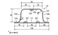
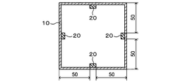
- the structural member 1 of the analysis model is composed of a hollow member 10 composed of a flat plate 11 and a hat-shaped member 12, and an FRP member 20 composed of CFRP.
- the flat plate 11 and the hat-shaped member 12 are spot-welded at the flange portion 12c of the hat-shaped member 12, and the interval between spot spots is 40 mm.
- the plate thickness of the flat plate 11 and the hat-shaped member 12 is 1.0 mm, and the yield stress is 700 MPa.
- the FRP member 20 is joined to two locations on the inner surface of the flat plate 11 and one location on the inner surface of the flat portion of the top plate portion 12 a of the hat-shaped member 12.
- the ends in the width direction W of the two FRP members 20 joined to the inner surface of the flat plate 11 are 40 mm from the ends in the width direction W of the flat plate 11, respectively, and the distance between the FRP members 20 is 30 mm.
- An end portion in the width direction W of the FRP member 20 joined to the top plate portion 12a is located at a position of 35 mm from the pair of opposing vertical wall portions 12b.
- the FRP member 20 is continuously joined from one end to the other end in the longitudinal direction L of the hollow member 10.
- one end face of the analysis model is completely restrained, and the other end face is restrained from causing in-plane deformation while allowing displacement of the hollow member 10 in the longitudinal direction L. .
- the end surface on the side that is completely constrained is referred to as a complete constraining side end surface, and the opposite end surface is referred to as a non-fully constraining side end surface.
- the collision simulation (A) was carried out under such a constraint condition that the end surface on the incomplete constraint side was compressed by 10 mm in the longitudinal direction of the hollow member 10.
- the collision speed at this time was 3 m / s, the element size was 1 mm, and the collision analysis was performed by the nonlinear structural analysis software LS-DYNA.
- the collision simulation (A) was performed with a plurality of analysis models having different thicknesses of the FRP member 20.
- the thickness of each FRP member 20 used for one analysis model is equal to each other.
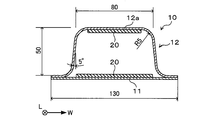
- an analysis model (Comparative Example 1) in which the FRP member 20 is not provided for the structural member 1 shown in FIG. 9, the entire inner surface of the flat plate 11 as shown in FIG. 10, and the top plate portion 12a.
- An analysis model (Comparative Example 2) in which the FRP member 20 was bonded to the entire inner surface of the flat part was created, and a collision simulation (A) was performed with each analysis model.
- FIG. 1 an analysis model in which the FRP member 20 is not provided for the structural member 1 shown in FIG. 9, the entire inner surface of the flat plate 11 as shown in FIG. 10, and the top plate portion 12a.
- An analysis model (Comparative Example 2) in which the FRP member 20 was bonded to the entire inner surface of the flat part was created, and a collision simulation (A) was performed with each analysis model.
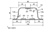
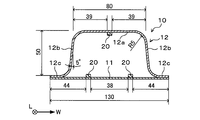
- the width of the FRP member is 10 mm, but the widths of the FRP members of Example 7 and Comparative Example 4 are 30 mm and 2 mm, respectively, as shown in FIGS. 11 and 12 (Table 1). reference).
- the full width 130 mm of the plane part P of Example 7 and Comparative Example 4 is the same as that in FIG. 9, and the sticking center position of the FRP member in FIG. 9 is the same.
- fibers whose FRP member fiber direction is within ⁇ 5 ° (within a range of ⁇ 5 ° to + 5 °) of the longitudinal direction of the FRP member are It was 80% or more.
- the results of the collision simulation (A) are shown in Table 1 below.
- the maximum reaction force that occurs when the end face on the incomplete restraint side is compressed was measured. Since the maximum reaction force is correlated with the buckling strength, it is an index for evaluating impact resistance. Further, the maximum reaction force / weight was calculated as an index for evaluating the weight efficiency of impact resistance, and the ratio of the weight efficiency in each example to the weight efficiency of Comparative Example 1 in which no FRP member was provided was calculated. Moreover, the bending rigidity of the FRP member single body in the FRP joint part in any one place of a structural member and the bending rigidity of the plane part P in a FRP joint part were each calculated, and ratio (bending rigidity ratio) of both was computed.
- the value of the "total width of the FRP junction P A / planar portion P overall width ⁇ 100" and the "PA-width / flat portion width” (unit:%) is defined as, the example, in Comparative Example This value was calculated in each part where the FRP joint part such as the flat plate 11 and the top plate part 12a and the FRP non-joint part coexist. Further, in view of the condition of the formula (1) described in the above embodiment, the value ⁇ shown in the following formula (3) is defined, and in each part such as the flat plate 11 and the top plate portion 12a in each example and comparative example. This value ⁇ (unit:%) was calculated. In addition, in the case of FIG. 9 with the value of ⁇ in Table 1, the values at the top plate portion 12a and the values at three locations of the flat plate 11 are shown.
- Comparative Example 2 which is a structural member in which the FRP member 20 is joined to the entire flat portion of the hollow member 10 improves the bending rigidity but does not include the FRP member 20. Weight efficiency is lower than structural members. The reason for such a result is that there is no portion functioning like a simple support point in the central portion of the plane portion. More specifically, when the FRP member 20 is joined to the entire flat surface portion, the end portion in the width direction of the FRP joint portion approaches a simple support state, but the central portion in the width direction of the flat surface portion is in a simple support state. It is still a part that does not contribute to buckling strength. For this reason, the impact resistance corresponding to the increase in weight cannot be obtained.
- Examples 1 to 7 have higher weight efficiency than Comparative Example 1. Considering the result of this simulation, the weight efficiency can be improved when the bending stiffness ratio is 30 or more. In particular, when the FRP member 20 having a thickness of 6 times or more the plate thickness (1.0 mm) of the flat plate or hat-shaped member is joined, the weight efficiency is remarkably increased.
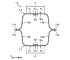
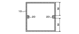
- the structural member 1 of the analysis model is composed of a square tube which is a hollow member 10, and an FRP member made of CFRP is joined to the inner surface of the square tube.
- the plate thickness of the square tube is 1.0 mm, and the yield stress is 700 MPa.
- one end surface of the analysis model is a completely constrained side end surface, and the other end surface is an incompletely constrained side end surface.
- the collision simulation (B) was performed under such a constraint condition that the end surface on the incomplete constraint side was compressed 20 mm in the longitudinal direction of the hollow member 10.
- the collision speed at this time was 3 m / s, the element size was 1 mm, and the collision analysis was performed by the nonlinear structural analysis software LS-DYNA.
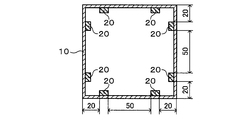
- the collision simulation (B) was performed with a plurality of analysis models in which the joining positions of the FRP member 20 are different as shown in FIGS.
- the thickness of each FRP member 20 used for one analysis model is equal to each other.
- an analysis model (Comparative Example 5) in which the FRP member 20 is not provided in the structural member shown in FIG. 14 is created and a collision simulation (B) is performed.
- the structural member shown in FIG. An analysis model was created and a collision simulation (B) was performed.
- the fibers in which the directions of the fibers of the FRP members of Examples 9 and 10 are within ⁇ 5 ° of the longitudinal direction of the FRP members are 80% of the total fibers in volume fraction, and Comparative Examples 5 and 6, Example 8, The fibers in which the direction of the fibers of the 11 to 13 FRP members was within ⁇ 5 ° of the longitudinal direction of the FRP member was 100% of the total fiber in terms of volume fraction.
- the structural members of Examples 8 to 13 to which the FRP member 20 is joined are greatly improved in weight efficiency compared to the structural member of Comparative Example 5 in which the FRP member 20 is not provided. Yes.
- the weight efficiency can be improved by providing each FRP member 20 on a plane portion facing each other. Can be improved.
- the weight efficiency can be improved by increasing the number of FRP members 20 provided in the same plane portion. This is because the number of locations approaching the simple support state increases in the same plane portion, and the range of the effective width increases.
- Example 9 When comparing Example 9 and Example 12, although the number of FRP members 20 is the same, the weight efficiency of impact resistance is higher in Example 9. The reason why such a difference occurs is that the distance between the adjacent FRP members 20 at the central portion of the plane portion is narrower in the ninth embodiment, and the effect of the effective width is not at the FRP non-intensity in the central portion of the plane portion. It is easy to reach the joint portion, and the FRP non-joint portion is in a state of effectively contributing to the improvement of the buckling strength. Therefore, it is preferable that the FRP member 20 is provided so that the length of the FRP non-joining portion of the plane portion is equal to or less than the effective width.
- the present invention can be used for a floor cross member of an automobile, for example.
Abstract
In order to improve impact-resistant weight efficiency in an automobile structural member, this automobile structural member comprises: a hollow member having a flat section; and an FRP member joined to at least one location on the flat section. The automobile structural member is characterized by: the FRP member being joined to at least a 0.1L1–0.9L1 section of the length L1 in the longitudinal direction of the hollow member; an FRP joined section being a section having the FRP member joined thereto and an FRP non-joined section being a section not having the FRP member joined thereto being formed at the 0.1L1–0.9L1 site in the flat section; the total width of the FRP joined section in the flat section being 8%–60% of the total width of the flat section; and the bending rigidity of the FRP member in the FRP joining section in the flat section being at least 30 times the bending rigidity of the flat section excluding the FRP member.
Description
(関連出願の相互参照)
本願は、2018年4月9日に日本国に出願された特願2018-074647号に基づき、優先権を主張し、その内容をここに援用する。 (Cross-reference of related applications)
This application claims priority based on Japanese Patent Application No. 2018-074647 for which it applied to Japan on April 9, 2018, and uses the content here.
本願は、2018年4月9日に日本国に出願された特願2018-074647号に基づき、優先権を主張し、その内容をここに援用する。 (Cross-reference of related applications)
This application claims priority based on Japanese Patent Application No. 2018-074647 for which it applied to Japan on April 9, 2018, and uses the content here.
本発明は、自動車構造部材に関する。
The present invention relates to an automobile structural member.
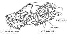
自動車構造部材には衝突時に乗員を保護するための耐衝撃性が求められる。例えば図1に示すようなフロアクロスメンバには側面衝突時における耐衝撃性が求められ、フロアトンネルおよびサイドシルには前面衝突時および後面衝突時における耐衝撃性が求められる。また、フロントサイドメンバーは、フロントサイドメンバーフロントと、フロントサイドメンバーリアで構成されるが、フロントサイドメンバーリアには前面衝突時における耐衝撃性が求められる。自動車の衝突安全性をさらに高めるためには、各構造部材の耐衝撃性を向上させることが重要である。
Automotive structural members are required to have impact resistance to protect passengers in the event of a collision. For example, the floor cross member as shown in FIG. 1 is required to have impact resistance at the time of side collision, and the floor tunnel and the side sill are required to have impact resistance at the time of frontal collision and rearward collision. The front side member is composed of a front side member front and a front side member rear, and the front side member rear is required to have impact resistance at the time of a frontal collision. In order to further improve the collision safety of automobiles, it is important to improve the impact resistance of each structural member.
耐衝撃性を向上させる技術として、特許文献1にはフロアパネルの車内側に接合されたハット状部材と、そのハット状部材の上部に接合されたU字状部材で構成されたフロアクロスメンバが開示されている。特許文献1のフロアクロスメンバにおいては、自動車の側面衝突時に入力される衝撃荷重をハット状部材とU字状部材に分散して伝達させることで耐衝撃性を向上させている。
As a technique for improving impact resistance, Patent Document 1 discloses a floor cross member composed of a hat-shaped member joined to the inside of a floor panel and a U-shaped member joined to the top of the hat-shaped member. It is disclosed. In the floor cross member of Patent Document 1, impact resistance is improved by dispersing and transmitting an impact load input at the time of a side collision of an automobile to a hat-shaped member and a U-shaped member.
また、特許文献2には、アルミ合金の中空フレーム(衝撃吸収材)にFRP部材(高強度軽量材)を接合した複合構造の衝撃吸収用部材が開示されている。特許文献2に記載の技術では、中空フレームの長手方向にFRP部材がほぼ100%接合された構成が開示され、これにより、衝撃エネルギー吸収機能と変形阻止機能を両立させている。
Patent Document 2 discloses a shock absorbing member having a composite structure in which an FRP member (high-strength lightweight material) is joined to an aluminum alloy hollow frame (shock absorbing material). The technique described in Patent Document 2 discloses a configuration in which almost 100% of the FRP members are joined in the longitudinal direction of the hollow frame, thereby achieving both an impact energy absorption function and a deformation prevention function.
また、特許文献3には、金属製の中空フレームの壁部にCFRP製の補強材を接着させる技術が開示されている。特許文献3に記載の技術では、引張荷重が集中する場所だけに補強材を貼り付けることで軽量化と耐荷重を両立させている。
Patent Document 3 discloses a technique for bonding a CFRP reinforcing material to a wall portion of a metal hollow frame. In the technique described in Patent Document 3, the weight reduction and the load resistance are achieved by attaching the reinforcing material only to the place where the tensile load is concentrated.
また、特許文献4には、自動車部材に活用する金属-CFRP複合部材が開示されている。特許文献4に記載の技術では、補強材(CFRP)を接着させるための熱硬化性接着剤の残留剪断応力を低減させることができる。
Further, Patent Document 4 discloses a metal-CFRP composite member used for automobile members. In the technique described in Patent Document 4, the residual shear stress of the thermosetting adhesive for adhering the reinforcing material (CFRP) can be reduced.
また、特許文献5には、CFRP製のパッチを用いて自動車の車体部材を補強する車体製造方法が開示されている。特許文献5に記載の技術では、パッチを応力集中部の引張面に貼着あるいはボルト止めすることで補強効果を高め、補強効果の大小を容易に調整することができる。
Patent Document 5 discloses a vehicle body manufacturing method in which a vehicle body member of an automobile is reinforced using a CFRP patch. In the technique described in Patent Document 5, the reinforcing effect can be enhanced by sticking or bolting the patch to the tensile surface of the stress concentration portion, and the magnitude of the reinforcing effect can be easily adjusted.
自動車構造部材には耐衝撃性の向上が求められる一方、燃費向上のために車体重量の軽量化も求められる。このため、構造部材としての耐衝撃性と軽量化を両立させるという観点では、単位重量あたりの耐衝撃性を示す指標となる耐衝撃性の重量効率を向上させることが望まれる。しかしながら、特許文献1のフロアクロスメンバは、ハット状部材やU字状部材等を用いて高さ方向に二つの閉断面を有するように構成される必要があることから、耐衝撃性の向上度合いに対して重量の増加が顕著となり、耐衝撃性の重量効率が低下する。
While automobile structural members are required to have improved impact resistance, it is also required to reduce the weight of the vehicle body in order to improve fuel efficiency. For this reason, from the viewpoint of achieving both impact resistance and weight reduction as a structural member, it is desired to improve the weight efficiency of impact resistance, which is an index indicating the impact resistance per unit weight. However, since the floor cross member of Patent Document 1 needs to be configured to have two closed cross sections in the height direction using a hat-shaped member, a U-shaped member, or the like, the degree of improvement in impact resistance On the other hand, the increase in weight becomes remarkable, and the weight efficiency of impact resistance decreases.
また、上記特許文献2では中空フレームの長手方向にFRP部材がほぼ100%接合された構成を開示しているが、FRP部材の接合箇所には更なる工夫の余地があり、耐衝撃性と軽量化の両立のためには更なる重量効率の向上が求められる。また、上記特許文献3では引張荷重が集中する場所だけに補強材を貼り付けるといったことが記載されているが、耐衝撃性に関しての好適な補強材の構成については言及されておらず、耐衝撃性と軽量化の両立のためには、更なる工夫が求められる。
Moreover, although the patent document 2 discloses a configuration in which the FRP member is almost 100% joined in the longitudinal direction of the hollow frame, there is room for further contrivance at the joining location of the FRP member, and impact resistance and light weight. Further improvement in weight efficiency is required for achieving compatibility. In addition, Patent Document 3 describes that a reinforcing material is attached only to a place where a tensile load is concentrated. However, a configuration of a suitable reinforcing material with respect to impact resistance is not mentioned, and impact resistance is not described. In order to achieve both compatibility and weight reduction, further ingenuity is required.
また、上記特許文献4は補強材(CFRP)を接着させるための熱硬化性接着剤の残留剪断応力を低減させる技術であり、上記特許文献5はパッチを応力集中部の引張面に貼着あるいはボルト止めすることで補強を行う技術であるが、これらの文献は共に耐衝撃性に伴うFRP部材の好適な接着位置や重量効率の向上技術に関し十分に言及しているとはいえず、更なる改良の余地がある。
Patent Document 4 is a technique for reducing the residual shear stress of a thermosetting adhesive for adhering a reinforcing material (CFRP), and Patent Document 5 is a technique in which a patch is attached to a tensile surface of a stress concentration portion or Although it is a technique to reinforce by bolting, both of these documents do not fully refer to a suitable adhesion position of FRP member accompanying impact resistance and a technique for improving the weight efficiency. There is room for improvement.
本発明は、上記事情に鑑みてなされたものであり、自動車構造部材において、耐衝撃性の重量効率を向上させることを目的とする。
The present invention has been made in view of the above circumstances, and an object thereof is to improve the weight efficiency of impact resistance in automobile structural members.
上記課題を解決するため、本発明によれば、平面部を有する中空部材と、前記平面部の少なくとも一箇所に接合されるFRP部材と、を備えた自動車構造部材であって、前記FRP部材は、前記中空部材の長手方向の長さLの少なくとも0.1L~0.9Lの部位に接合され、前記平面部には、前記0.1L~0.9Lの部位において、前記FRP部材が接合された部分であるFRP接合部と、前記FRP部材が接合されていない部分であるFRP非接合部と、が形成され、前記平面部において、前記FRP接合部の幅の合計は前記平面部の全幅の8~60%であり、前記平面部において前記FRP接合部での前記FRP部材の曲げ剛性は、前記FRP部材を除いた前記平面部の曲げ剛性の30倍以上であることを特徴とする、自動車構造部材が提供される。
In order to solve the above problems, according to the present invention, there is provided an automotive structural member comprising a hollow member having a flat surface portion and an FRP member joined to at least one location of the flat surface portion, wherein the FRP member is The hollow member is joined to at least a portion of the longitudinal length L of 0.1L to 0.9L, and the FRP member is joined to the flat portion at the portion of 0.1L to 0.9L. A FRP joint portion that is a portion where the FRP member is not joined, and a FRP non-joint portion that is a portion where the FRP member is not joined. In the planar portion, the total width of the FRP joint portion is the total width of the planar portion. 8 to 60%, and the flexural rigidity of the FRP member at the FRP joint portion in the flat surface portion is 30 times or more of the flexural rigidity of the flat surface portion excluding the FRP member. Construction Wood is provided.
前記FRP部材の曲げ剛性は、前記FRP部材を除いた前記平面部の曲げ剛性の100倍以上であっても良い。
The bending rigidity of the FRP member may be 100 times or more of the bending rigidity of the flat portion excluding the FRP member.
前記FRP部材の厚さは、前記平面部の厚さの6倍以上であっても良い。
The thickness of the FRP member may be 6 times or more the thickness of the planar portion.
前記平面部における前記FRP非接合部のそれぞれの幅Dが以下の式(1)を満たしても良い。

但し、t:前記平面部の厚さ、E:前記平面部のヤング率、σy:前記平面部の降伏応力
Each width D of the FRP non-joining part in the plane part may satisfy the following formula (1).
Where t: thickness of the plane part, E: Young's modulus of the plane part, σ y : yield stress of the plane part
前記FRP部材は、前記中空部材の内部空間側の面に接合されても良い。
The FRP member may be joined to the surface of the hollow member on the inner space side.
前記FRP部材はCFRPからなるCFRP部材であっても良い。
The FRP member may be a CFRP member made of CFRP.
前記FRP部材はGFRPからなるGFRP部材であっても良い。
The FRP member may be a GFRP member made of GFRP.
前記CFRP部材の繊維方向が当該CFRP部材の長手方向に対し±5°以内の範囲内にある繊維が、繊維全体の80%以上であっても良い。
80% or more of the total fibers may be fibers in which the fiber direction of the CFRP member is within ± 5 ° with respect to the longitudinal direction of the CFRP member.
上記自動車構造部材は、フロアクロスメンバ、フロアトンネル、フロントサイドメンバーリアおよびサイドシルの少なくともいずれかの部材であっても良い。
The automobile structural member may be at least one of a floor cross member, a floor tunnel, a front side member rear, and a side sill.
なお、本発明に係る自動車構造部材には、FRP部材が中空部材の平面部全体に接合された構造部材は含まれない。
Note that the automobile structural member according to the present invention does not include a structural member in which the FRP member is bonded to the entire flat portion of the hollow member.
本発明によれば、自動車構造部材において、耐衝撃性の重量効率を向上させることができる。
According to the present invention, it is possible to improve the weight efficiency of impact resistance in automobile structural members.
以下、本発明の実施形態について、図面を参照しながら説明する。なお、本明細書および図面において、実質的に同一の機能構成を有する要素においては、同一の符号を付することにより重複説明を省略する。
Hereinafter, embodiments of the present invention will be described with reference to the drawings. In the present specification and drawings, elements having substantially the same functional configuration are denoted by the same reference numerals, and redundant description is omitted.
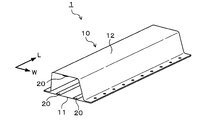
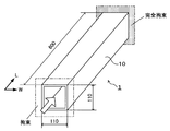
図2および図3に示すように本実施形態の自動車構造部材1(以下、単に「構造部材1」とも呼称)は、中空部材10と、中空部材10に接合された例えばCFRP(炭素繊維強化樹脂)からなるFRP部材20で構成されている。FRP部材20を構成する樹脂および強化繊維等については後述する。なお、本実施形態においては中空部材10の長手方向Lの両端部がそれぞれ開口した状態にあるが、その開口部が他の平板(不図示)等で覆われていても良い。他の平板とは、例えば、構造部材1がフロアクロスメンバであれば、フロアクロスメンバの端部と接合されるサイドシルまたはフロアトンネル等の他部材の壁部である。
As shown in FIGS. 2 and 3, the automobile structural member 1 (hereinafter also simply referred to as “structural member 1”) of the present embodiment includes a hollow member 10 and, for example, CFRP (carbon fiber reinforced resin) joined to the hollow member 10. FRP member 20 consisting of The resin and reinforcing fibers that constitute the FRP member 20 will be described later. In the present embodiment, both ends of the hollow member 10 in the longitudinal direction L are open, but the openings may be covered with another flat plate (not shown) or the like. For example, when the structural member 1 is a floor cross member, the other flat plate is a wall portion of another member such as a side sill or a floor tunnel that is joined to an end portion of the floor cross member.
中空部材10は、平板11と、中空部材10の長手方向Lに垂直な断面における形状がハット形状である部材(以下、“ハット状部材12”)で構成されている。平板11やハット状部材12の素材は特に限定されないが、例えば鋼板やアルミニウム板が用いられる。なお、本明細書では、構造部材1の平面視における中空部材10の閉断面が延伸する長尺方向を部材の長手方向Lと称し、平面視において当該長手方向Lに垂直な方向を“幅方向W”と称す。また、平板11の表面のうち、ハット状部材12に対向する側の面、すなわち中空部材10の内部空間側の面を“内面”と称し、反対側の面を“外面”と称す。また、ハット状部材12の表面のうち、中空部材10の内部空間側の面を“内面”と称し、反対側の面を“外面”と称す。
The hollow member 10 includes a flat plate 11 and a member whose cross section perpendicular to the longitudinal direction L of the hollow member 10 is a hat shape (hereinafter referred to as “hat-shaped member 12”). Although the raw material of the flat plate 11 and the hat-shaped member 12 is not specifically limited, For example, a steel plate or an aluminum plate is used. In the present specification, the longitudinal direction in which the closed section of the hollow member 10 in the plan view of the structural member 1 extends is referred to as the longitudinal direction L of the member, and the direction perpendicular to the longitudinal direction L in the plan view is referred to as the “width direction”. W ". Of the surface of the flat plate 11, the surface facing the hat-shaped member 12, that is, the surface on the inner space side of the hollow member 10 is referred to as “inner surface”, and the opposite surface is referred to as “outer surface”. Further, among the surfaces of the hat-shaped member 12, the surface on the inner space side of the hollow member 10 is referred to as an “inner surface”, and the opposite surface is referred to as an “outer surface”.
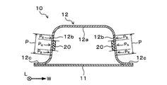
図3に示すようにハット状部材12は、天板部12aと、天板部12aの幅方向Wの両端部から延び、かつ天板部12aに対して傾斜した縦壁部12bと、縦壁部12bの先端部から幅方向Wの外側に延びたフランジ部12cを有している。図2および図3に示すように本実施形態のFRP部材20は、平板11の内面における二箇所と、ハット状部材12の天板部12aの内面における一箇所に接合されている。平板11に接合されたFRP部材20は間隔をおいて配置されており、ハット状部材12に接合されたFRP部材20は天板部12aの平面部Pに接合されている。各FRP部材20は、中空部材10の長手方向Lに沿って延びており、本実施形態においては中空部材10の長手方向Lの一方の端部から他方の端部まで連続的に延びているが、重量効率を向上させるという観点においては、FRP部材20の長手方向Lの長さは、中空部材10の長手方向Lの長さL1の80%以上であれば良い。具体的には、中空部材10の長手方向Lの長さをL1とした場合の、少なくとも当該長手方向Lにおける0.1L1~0.9L1の部位にFRP部材20が接合されている必要がある。つまり、中空部材の長さ方向の中央から2つの両端方向に長さL1の40%の距離だけ離れた部位までにFRP部材20が接合されている必要がある。これは、中空部材10の長手方向両端部は、通常、他の部材に接続し拘束状態となっているため、中空部材10の長手方向Lの長さをL1における両端部(0~0.1L1及び0.9L1~1.0L1)、つまり両端から長さL1の10%まで部位には、必ずしもFRP部材20を接合しなくとも耐衝撃性が担保されるからである。また、FRP部材20の長手方向が、中空部材10の長手方向Lに対し-10°以上10°以下(±10°以内)の範囲内であることが好ましい。上記の角度はー5°~+5°以内(±5°以内)であることがより好ましい。
As shown in FIG. 3, the hat-shaped member 12 includes a top plate portion 12a, a vertical wall portion 12b extending from both ends of the top plate portion 12a in the width direction W and inclined with respect to the top plate portion 12a, and a vertical wall. It has a flange portion 12c extending outward in the width direction W from the tip portion of the portion 12b. As shown in FIGS. 2 and 3, the FRP member 20 of this embodiment is joined to two locations on the inner surface of the flat plate 11 and one location on the inner surface of the top plate portion 12 a of the hat-shaped member 12. The FRP members 20 bonded to the flat plate 11 are arranged at intervals, and the FRP members 20 bonded to the hat-shaped member 12 are bonded to the flat surface portion P of the top plate portion 12a. Each FRP member 20 extends along the longitudinal direction L of the hollow member 10. In this embodiment, each FRP member 20 continuously extends from one end to the other end in the longitudinal direction L of the hollow member 10. In terms of improving weight efficiency, the length in the longitudinal direction L of the FRP member 20 may be 80% or more of the length L1 in the longitudinal direction L of the hollow member 10. Specifically, when the length of the hollow member 10 in the longitudinal direction L is L1, the FRP member 20 needs to be joined to at least a portion of 0.1L1 to 0.9L1 in the longitudinal direction L. That is, it is necessary that the FRP member 20 be joined to a portion separated by a distance of 40% of the length L1 from the center in the length direction of the hollow member in the two end directions. This is because both ends in the longitudinal direction of the hollow member 10 are normally connected to other members and are in a restrained state, and therefore the length in the longitudinal direction L of the hollow member 10 is set to both ends (0 to 0.1L1) in L1. And 0.9L1 to 1.0L1), that is, impact resistance is ensured even if the FRP member 20 is not necessarily joined to the portion from both ends to 10% of the length L1. The longitudinal direction of the FRP member 20 is preferably in the range of −10 ° to 10 ° (within ± 10 °) with respect to the longitudinal direction L of the hollow member 10. The angle is more preferably within −5 ° to + 5 ° (within ± 5 °).
なお、本実施形態のハット状部材12においては、天板部12aと縦壁部12bとがそれぞれ曲面で接続されていることから、天板部12aの幅方向Wの端部には曲面が含まれることになるが、本明細書における平面と曲面を含む部材の“平面部”とは、平面と曲面の境界部分、すなわち一方の曲面のR止まりから他方の曲面のR止まりまでの部分を指しても良い。この定義によれば、ハット状部材12の縦壁部12bの平面部Pとは、天板部12a側の曲面のR止まりからフランジ部12c側の曲面のR止まりまでの部分となる。また、“平面部”のより詳細な定義としては、部材(天板部12a、縦壁部12b等)の板厚をt、曲率半径をrとした場合に、r/t≧10000を平面部Pと規定しても良い。平板11の表面も当然に平面部Pであることから、本実施形態で用いられているFRP部材20は、全て中空部材10の平面部Pの内面に設けられていることになる。なお、後述する例で示すように、中空部材10は、曲面部を有さず、平面部のみで構成されていてもよい。
In addition, in the hat-shaped member 12 of this embodiment, since the top-plate part 12a and the vertical wall part 12b are each connected by the curved surface, the curved surface is contained in the edge part of the width direction W of the top-plate part 12a. In this specification, the term “plane portion” of a member including a plane and a curved surface refers to the boundary between the plane and the curved surface, that is, the portion from the R stop of one curved surface to the R stop of the other curved surface. May be. According to this definition, the flat surface portion P of the vertical wall portion 12b of the hat-shaped member 12 is a portion from the R stop of the curved surface on the top plate portion 12a side to the R stop of the curved surface on the flange portion 12c side. Further, as a more detailed definition of the “planar portion”, r / t ≧ 10000 is defined as plane portion when the plate thickness of a member (top plate portion 12a, vertical wall portion 12b, etc.) is t and the radius of curvature is r. P may be defined. Since the surface of the flat plate 11 is naturally the flat portion P, the FRP member 20 used in this embodiment is all provided on the inner surface of the flat portion P of the hollow member 10. In addition, as shown in the example mentioned later, the hollow member 10 does not have a curved surface part, and may be comprised only by the plane part.
平面部Pに対するFRP部材20の接合方法は特に限定されないが、例えば公知の接着剤を用いて平面部Pに貼り付けられることで接合される。このため、構造部材1は、例えば接着材により表面にFRP部材20が貼り付けられた状態の平板11と、接着剤により天板部12aの平面部P内面にFRP部材20が貼り付けられた状態のハット状部材12とが、ハット状部材12のフランジ部12cにおいてスポット溶接等の公知の接合手段により互いに接合されることで製造される。ただし、構造部材1の製造方法は上記の方法に限定されることはない。なお、接着剤を用いて中空部材10の平面部PにFRP部材20を貼り付けた構造部材1の断面を観察すれば、中空部材10の平面部PとFRP部材20との間に接着剤が存在していることを確認することができる。平面部PとFRP部材20との接合方法の具体例については後述する。
Although the joining method of the FRP member 20 with respect to the plane part P is not specifically limited, For example, it joins by affixing on the plane part P using a well-known adhesive agent. For this reason, the structural member 1 is a state in which the FRP member 20 is attached to the inner surface of the flat surface portion P of the top plate portion 12a by an adhesive and the flat plate 11 in a state where the FRP member 20 is attached to the surface by an adhesive, for example. The hat-shaped member 12 is manufactured by joining the flange-shaped member 12 of the hat-shaped member 12 to each other by a known joining means such as spot welding. However, the manufacturing method of the structural member 1 is not limited to said method. If the cross section of the structural member 1 in which the FRP member 20 is attached to the flat surface portion P of the hollow member 10 using an adhesive is observed, the adhesive is between the flat surface portion P of the hollow member 10 and the FRP member 20. It can be confirmed that it exists. A specific example of a method for joining the flat portion P and the FRP member 20 will be described later.
本実施形態の自動車構造部材1は以上のように構成されている。本実施形態の構造部材1によれば、FRP部材20が中空部材10の平面部Pに接合されていることにより、当該平面部Pにおける面外変形に対する曲げ剛性が大きくなり、衝撃荷重入力時の座屈現象の発生を抑えることができる。これにより構造部材1としての耐衝撃性を向上させることができる。
The automobile structural member 1 of the present embodiment is configured as described above. According to the structural member 1 of the present embodiment, since the FRP member 20 is joined to the flat surface portion P of the hollow member 10, the bending rigidity against the out-of-plane deformation in the flat surface portion P is increased, and an impact load is input. Occurrence of buckling phenomenon can be suppressed. Thereby, the impact resistance as the structural member 1 can be improved.
ここで、上記のように耐衝撃性が向上するメカニズムについて説明する。図4は従来の構造部材におけるハット状部材12の天板部12aを、板30の支持構造に例えた図であり、構造部材の幅方向Wを含む面の断面を模式的に示したものである。図5は本実施形態の構造部材1におけるハット状部材12の天板部12aを、板30の支持構造に例えた図であり、構造部材1の幅方向Wを含む面の断面を模式的に示したものである。図4に示すように、従来の構造部材においては板30の両端部が支持点31(ハット状部材12の縦壁部12bに相当)により単純支持状態にあるが、板30の中央部は支持されていない。このため、座屈耐力に影響を与える部分となる、いわゆる有効幅bの範囲は板30の両端部近傍のみである。ここで、本明細書における「有効幅b」とは、von karmanの式で算出される有効幅であり両縁単純支持された平板の圧縮耐力に関して呼称されるものである。
Here, the mechanism for improving the impact resistance as described above will be described. FIG. 4 is a diagram in which the top plate portion 12a of the hat-shaped member 12 in the conventional structural member is compared to the support structure of the plate 30 and schematically shows a cross section of the surface including the width direction W of the structural member. is there. FIG. 5 is a diagram in which the top plate portion 12a of the hat-shaped member 12 in the structural member 1 of the present embodiment is compared to the support structure of the plate 30, and a cross section of the surface including the width direction W of the structural member 1 is schematically illustrated. It is shown. As shown in FIG. 4, in the conventional structural member, both ends of the plate 30 are in a simple support state by the support points 31 (corresponding to the vertical wall portion 12b of the hat-like member 12), but the central portion of the plate 30 is supported. It has not been. For this reason, the range of the so-called effective width b that becomes a part that affects the buckling strength is only in the vicinity of both ends of the plate 30. Here, the “effective width b” in the present specification is an effective width calculated by the formula of von karman, and is referred to as a compression strength of a flat plate simply supported on both edges.
一方、本実施形態の構造部材1においては、天板部12aの平面部P中央にFRP部材20が接合されていることによって当該部分の曲げ剛性が高まるため、図5のような板30の支持構造に例えると、板30の中央部に新たな単純支持点32が設けられたような状態となる。すなわち、板30の両端部および中央部が単純支持状態となり、有効幅bの範囲が従来の構造部材に対して増大し、その結果、座屈耐力が向上することになる。これにより構造部材1の耐衝撃性が向上する。また、鋼板等従来の金属部材からなる補強部材を用いて中空部材10を補強する場合と比較して、重量の増加を抑えることができるため、FRP部材20が設けられていない構造部材に対して耐衝撃性の重量効率を向上させることができる。
On the other hand, in the structural member 1 of the present embodiment, since the FRP member 20 is joined to the center of the flat surface portion P of the top plate portion 12a, the bending rigidity of the portion increases, so the support of the plate 30 as shown in FIG. For example, the structure is such that a new simple support point 32 is provided at the center of the plate 30. That is, both end portions and the central portion of the plate 30 are in a simple support state, and the range of the effective width b is increased as compared with the conventional structural member. As a result, the buckling strength is improved. Thereby, the impact resistance of the structural member 1 is improved. Moreover, since the increase in weight can be suppressed compared with the case where the hollow member 10 is reinforced using the reinforcement member which consists of conventional metal members, such as a steel plate, with respect to the structural member in which the FRP member 20 is not provided. The weight efficiency of impact resistance can be improved.
ここで、本明細書では、例えば図3に示すように、平面部PにおいてFRP部材20が接合された部分を“FRP接合部PA”と称す。このFRP接合部PAは、FRP部材20が接合されている部分の平面部Pと、当該部分に接合されているFRP部材20とを含む概念である。また、平面部PにおいてFRP部材20が接合されていない部分、すなわちFRP接合部PA以外の部分を“FRP非接合部PB”と称す。
In this specification, for example, as shown in FIG. 3, referred to as "FRP junction P A" portion of FRP member 20 is bonded in the plane part P. The FRP junction P A is a concept including a planar portion P of the portion FRP member 20 is joined, and a FRP member 20 which is joined to the portion. Further, referred in the plane portion P portion FRP member 20 is not bonded, i.e., the portion other than FRP junction P A and "FRP unbonded portion P B".
FRP接合部PAが上記のように単純支持状態に近づくようにするためには、FRP接合部PAにおけるFRP部材20の曲げ剛性と、FRP接合部PAにおけるFRP部材20を除いた部分、すなわちFRP接合部PAにおける平面部Pの曲げ剛性との比(以下、“曲げ剛性比”)が30以上である必要がある。この条件を満たすような曲げ剛性を有したFRP部材20が、中空部材10の平面部Pに接合されていれば、耐衝撃性を向上させることができると共に、耐衝撃性の重量効率をFRP部材20が設けられていない部材と同等またはそれ以上にすることができる。曲げ剛性比は、50以上、80以上、100以上、150以上、200以上または300以上であることがより好ましい。曲げ剛性比は大きいほど重量効率が向上するため、曲げ剛性の上限は特に限定されず、例えば、構造部材1の設計条件やコスト等の他の要因により適宜決定され得る。いくつか要因の中で、FRP曲部材の接着強度を考慮すると、曲げ剛性比を余り高くすること避けた方が好ましく、具体的には曲げ剛性比を50000以下とすることが好ましい。必要に応じて、曲げ剛性比を20000以下、10000以下、5000以下、1000以下、500以下としてもよい。
Parts FRP junction P A in order to be closer to a simply supported state as described above, except the bending rigidity of the FRP member 20 in the FRP junction P A, the FRP member 20 in the FRP junction P A, that ratio of the flexural rigidity of the flat portion P of the FRP junction P a (hereinafter, "flexural rigidity ratio") must be 30 or more. If the FRP member 20 having bending rigidity satisfying this condition is joined to the flat surface portion P of the hollow member 10, the impact resistance can be improved and the weight efficiency of the impact resistance can be improved. It can be equal to or more than a member in which 20 is not provided. The bending stiffness ratio is more preferably 50 or more, 80 or more, 100 or more, 150 or more, 200 or more, or 300 or more. Since the weight efficiency increases as the bending stiffness ratio increases, the upper limit of the bending stiffness is not particularly limited, and can be determined as appropriate depending on other factors such as the design conditions and cost of the structural member 1. Among several factors, in consideration of the adhesive strength of the FRP bending member, it is preferable to avoid excessively increasing the bending rigidity ratio, and specifically, it is preferable to set the bending rigidity ratio to 50000 or less. If necessary, the bending stiffness ratio may be 20000 or less, 10,000 or less, 5000 or less, 1000 or less, or 500 or less.
ここで、FRP部材20の曲げ剛性は、中空部材10の垂直横断面における、FRP部材20の形状から算出できる断面2次モーメントIと、FRP部材20の、中空部材10の長手方向Lの常温での引張試験から求められる弾性率Eとの積IEとして求めることができる。FRP部材20の形状から算出される断面2次モーメントIは、中空部材10の接着面(平面部Pに接着される面)に平行であり、且つ、FRP部材20の図心(重心位置)を通る直線を原点とし、接着面の垂直な方向をy軸、FRP部材の長さ方向およびy軸方向に垂直な方向をx軸とする座標系において下記式(2)により算出する。なお、式(2)におけるAは断面である。FRP部材20の断面形状は、一定であることが好ましいが、断面形状が変化する場合、断面2次モーメントの最小値をFRP部材20の断面2次モーメントとする。

Here, the flexural rigidity of the FRP member 20 is the cross-sectional secondary moment I that can be calculated from the shape of the FRP member 20 in the vertical cross section of the hollow member 10 and the normal temperature of the FRP member 20 in the longitudinal direction L of the hollow member 10. It can be obtained as the product IE with the elastic modulus E obtained from the tensile test. The cross-sectional secondary moment I calculated from the shape of the FRP member 20 is parallel to the bonding surface of the hollow member 10 (the surface bonded to the flat surface portion P), and the centroid (center of gravity position) of the FRP member 20 is The following equation (2) is used in a coordinate system in which the straight line passing through is the origin, the direction perpendicular to the bonding surface is the y-axis, the length direction of the FRP member and the direction perpendicular to the y-axis direction is the x-axis. In addition, A in Formula (2) is a cross section. The cross-sectional shape of the FRP member 20 is preferably constant, but when the cross-sectional shape changes, the minimum value of the cross-sectional secondary moment is set as the cross-sectional secondary moment of the FRP member 20.
平面部Pの断面2次モーメントIOは、平面部の板厚中央を通り板厚方向の垂直な面を基準に、その基準面に垂直な方向をy軸、中空部材10の長手方向Lおよびy軸方向に垂直な方向をx軸とする座標系において上記式(2)により算出する。平面部Pの曲げ剛性は、平面部Pの断面2次モーメントIOと、平面部Pの、平面部Pの長手方向Lの常温での引張試験から求められる弾性率EOとの積IOEOとして求めることができる。したがって、前記曲げ剛性比は、IE/IOEOとして求めることができる。なお、平面部Pの弾性率EOとFRP部材2の弾性率Eについては、上記の引張試験を省略し、公知の文献に記載されている当該素材の弾性率をもちいてもよい。
The cross-sectional secondary moment I O of the plane portion P is based on a plane perpendicular to the thickness direction passing through the center of the thickness of the plane portion, and the direction perpendicular to the reference plane is the y axis, the longitudinal direction L of the hollow member 10 and Calculation is performed by the above equation (2) in a coordinate system in which the direction perpendicular to the y-axis direction is the x axis. The bending rigidity of the plane portion P is the product I O of the cross-sectional secondary moment I O of the plane portion P and the elastic modulus E O obtained from a tensile test at normal temperature in the longitudinal direction L of the plane portion P. It can be determined as EO . Therefore, the bending stiffness ratio can be obtained as IE / I O E O. In addition, about the elasticity modulus EO of the plane part P, and the elasticity modulus E of the FRP member 2, the said tensile test may be abbreviate | omitted and the elasticity modulus of the said material described in the well-known literature may be used.
図5のような板30の支持構造において、中空部材10の軽量化と座屈耐力の向上を両立させるためには、FRP接合部PAの幅の合計は、平面部Pの全幅の8~60%とする必要がある。FRP接合部PAの幅の合計が平面部Pの全幅の60%超の場合、座屈耐力の向上効果に見合った軽量化効果が得られない。一方、FRP接合部PAの幅の合計が平面部Pの全幅の8%未満の場合、FRP部材20による重量増に見合った座屈耐力の向上効果が得られない可能性があるためである。必要に応じて、この比率(FRP接合部PAの幅の合計/平面部Pの全幅)の上限を50%、40%、30%又は20%としてもよく、この比率の下限を10%、12%又は14%としてもよい。中空部材10の軽量化と座屈耐力の向上を共に実現するために、隣り合う単純支持点31、32の間隔を有効幅bの0.5~1.6倍の範囲内とすることが好ましい。すなわち、FRP非接合部PBの幅Dが、von
Karmanの式で算出される有効幅bの0.5~1.6倍の範囲内となることが好ましい。したがって、FRP部材20は、FRP非接合部PBのそれぞれの幅Dが下記式(1)を満たすように設けられていることが好ましい。これにより耐衝撃性を向上させることができる。なお、重量効率の観点からは、FRP非接合部PBの幅Dの値は大きい方が重量低減が図れるため、下記式(1)を満たす幅Dの最大値がより好ましい。必要に応じて、幅Dの下限を有効幅bの0.6倍、0.7倍又は0.8倍としてもよく、幅Dの上限を2.5倍又は2.0倍に緩和してもよいし、1.5倍、1.4倍、1.3倍又は1.2倍としてもよい。

但し、t:前記平面部の厚さ、E:前記平面部のヤング率、σy:前記平面部の降伏応力
なお、FRP非接合部PBのそれぞれの幅Dとは、隣接するFRP部材20がある場合には、隣接するFRP部材20同士の幅方向Wの間隔であり、隣接するFRP部材20がない場合には、FRP部材20(ただし、接着面の平面部Pの端部に最も近い位置)から平面部Pの端部までの幅方向の距離でもある。つまり、隣接するFRP部材20同士の幅方向Wの間隔と、FRP部材20(ただし、接着面の平面部Pの端部に最も近い位置)から平面部Pの端部までの幅方向の距離が、上記式(1)を満たすことが好ましい。 In the support structure of theplate 30 as shown in FIG. 5, in order to simultaneously improve the weight and buckling strength of the hollow member 10, the total width of the FRP junction P A is 8 to the total width of the flat portion P It needs to be 60%. If the sum of the width of the FRP junction P A is 60% of the overall width of the flat portion P, not lighter effect corresponding to the effect of improving the buckling strength can not be obtained. On the other hand, if the sum of the width of the FRP junction P A is less than 8% of the total width of the planar portion P, it is because there is a possibility that the effect of improving the buckling strength commensurate with the weight increase due to FRP member 20 can not be obtained . If necessary, up to 50% of this ratio (total width of the total / flat portion P of the width of the FRP junction P A), 40% may be 30% or 20%, the lower limit of the ratio of 10% It may be 12% or 14%. In order to realize both the weight reduction of the hollow member 10 and the improvement of the buckling strength, it is preferable to set the interval between the adjacent simple support points 31 and 32 within the range of 0.5 to 1.6 times the effective width b. . That is, the width D of the FRP non-joining portion P B is von
It is preferably within a range of 0.5 to 1.6 times the effective width b calculated by Karman's equation. Therefore, it is preferable that theFRP member 20 is provided so that each width D of the FRP non-joining portion P B satisfies the following formula (1). Thereby, impact resistance can be improved. From the viewpoint of weight efficiency, the larger the value of the width D of the FRP non-joined portion P B , the more the weight can be reduced. Therefore, the maximum value of the width D that satisfies the following formula (1) is more preferable. If necessary, the lower limit of the width D may be 0.6 times, 0.7 times, or 0.8 times the effective width b, and the upper limit of the width D is relaxed to 2.5 times or 2.0 times. Alternatively, it may be 1.5 times, 1.4 times, 1.3 times, or 1.2 times.
However, t: thickness of the plane part, E: Young's modulus of the plane part, σ y : yield stress of the plane part Note that each width D of the FRP non-joined part P B is the adjacent FRP member 20. If there is, it is the interval in the width direction W between the adjacent FRP members 20, and if there is no adjacent FRP member 20, the FRP member 20 (however, closest to the end of the flat surface portion P of the bonding surface) It is also the distance in the width direction from the position) to the end of the plane portion P. That is, the distance in the width direction W between adjacent FRP members 20 and the distance in the width direction from the FRP member 20 (however, the position closest to the end of the flat portion P of the bonding surface) to the end of the flat portion P are as follows. It is preferable to satisfy the above formula (1).
Karmanの式で算出される有効幅bの0.5~1.6倍の範囲内となることが好ましい。したがって、FRP部材20は、FRP非接合部PBのそれぞれの幅Dが下記式(1)を満たすように設けられていることが好ましい。これにより耐衝撃性を向上させることができる。なお、重量効率の観点からは、FRP非接合部PBの幅Dの値は大きい方が重量低減が図れるため、下記式(1)を満たす幅Dの最大値がより好ましい。必要に応じて、幅Dの下限を有効幅bの0.6倍、0.7倍又は0.8倍としてもよく、幅Dの上限を2.5倍又は2.0倍に緩和してもよいし、1.5倍、1.4倍、1.3倍又は1.2倍としてもよい。
なお、FRP非接合部PBのそれぞれの幅Dとは、隣接するFRP部材20がある場合には、隣接するFRP部材20同士の幅方向Wの間隔であり、隣接するFRP部材20がない場合には、FRP部材20(ただし、接着面の平面部Pの端部に最も近い位置)から平面部Pの端部までの幅方向の距離でもある。つまり、隣接するFRP部材20同士の幅方向Wの間隔と、FRP部材20(ただし、接着面の平面部Pの端部に最も近い位置)から平面部Pの端部までの幅方向の距離が、上記式(1)を満たすことが好ましい。 In the support structure of the
It is preferably within a range of 0.5 to 1.6 times the effective width b calculated by Karman's equation. Therefore, it is preferable that the
また、FRP部材20の厚さは、FRP部材20が接合された平面部Pの厚さの6倍以上であることが好ましい。平面部Pの厚さの4倍以上、8倍以上または10倍以上としてもよい。FRP部材20の厚さの上限を特に定める必要はないが、平面部Pの厚さの15倍以下又は20倍以下としてもよい。これにより耐衝撃性の重量効率が高くなり、重量の増加分に対する耐衝撃性の向上度合いが大きくなる。FRP部材20の厚さの上限は特に限定されないが、重量やコスト、接合箇所のスペース等に応じて定まる。なお、FRP部材20として、CFRPやそれ以外の種々のFRPからなるFRP部材を用いるようないかなる場合であっても、FRP部材の厚さが、FRPが接合された平面部Pの厚さの6倍以上であれば、重量の増加分に対する耐衝撃性の向上度合いを確実に大きくすることができる。FRP部材20の幅は、平面部Pの幅や、平面部Pに接合されるFRP部材20の数、構造部材1の設計条件やコスト等の他の要因によって適宜変更されるものであるが、例えば5~15mmである。
Further, the thickness of the FRP member 20 is preferably 6 times or more the thickness of the plane portion P to which the FRP member 20 is joined. It is good also as 4 times or more of the thickness of the plane part P, 8 times or more, or 10 times or more. The upper limit of the thickness of the FRP member 20 is not particularly required, but may be 15 times or less or 20 times or less the thickness of the plane portion P. As a result, the weight efficiency of impact resistance is increased, and the degree of improvement in impact resistance with respect to the increase in weight is increased. The upper limit of the thickness of the FRP member 20 is not particularly limited, but is determined according to the weight, cost, space at the joining location, and the like. In any case where an FRP member made of CFRP or other various FRPs is used as the FRP member 20, the thickness of the FRP member is 6 of the thickness of the plane portion P to which the FRP is joined. If it is twice or more, the degree of improvement in impact resistance against an increase in weight can be reliably increased. The width of the FRP member 20 is appropriately changed depending on other factors such as the width of the plane portion P, the number of FRP members 20 joined to the plane portion P, the design conditions and cost of the structural member 1, For example, 5 to 15 mm.
以上のように、本実施形態の自動車構造部材1によれば、中空部材10の平面部PにFRP部材20が接合されていることで、構造部材1の耐衝撃性の重量効率を向上させることができる。このような構造部材1は、自動車の車体を構成する部材のうち、衝突時に軸力が作用する箇所の部材として用いられることが好ましい。例えばフロアクロスメンバ、フロアトンネル、フロントサイドメンバーリアおよびサイドシルの少なくともいずれかの部材として用いられることが好ましい。
As described above, according to the automobile structural member 1 of the present embodiment, the FRP member 20 is joined to the flat surface portion P of the hollow member 10 to improve the weight efficiency of the impact resistance of the structural member 1. Can do. Such a structural member 1 is preferably used as a member at a location where an axial force acts during a collision among members constituting a vehicle body of an automobile. For example, it is preferably used as a member of at least one of a floor cross member, a floor tunnel, a front side member rear, and a side sill.
さらに、本実施形態のような構造部材1に使用される程度のFRP部材20の量であれば、FRP部材20が接合された状態の構造部材1を溶解させても鋼の不純物が過度に増加するようなことはない。したがって、本実施形態のような構造部材1は、スクラップとして構造部材1を再利用する際に中空部材10とFRP部材20を分別する必要がなく、リサイクル性に優れている。
Furthermore, if the amount of the FRP member 20 is such that it is used for the structural member 1 as in this embodiment, the impurities in the steel will increase excessively even if the structural member 1 in a state where the FRP member 20 is joined is dissolved. There is nothing to do. Therefore, the structural member 1 as in the present embodiment does not need to separate the hollow member 10 and the FRP member 20 when the structural member 1 is reused as scrap, and is excellent in recyclability.
以上、本発明の実施形態について説明したが、本発明はかかる例に限定されない。当業者であれば、特許請求の範囲に記載された技術的思想の範疇内において、各種の変更例または修正例に想到しうることは明らかであり、それらについても当然に本発明の技術的範囲に属するものと了解される。
As mentioned above, although embodiment of this invention was described, this invention is not limited to this example. It is obvious for those skilled in the art that various changes or modifications can be conceived within the scope of the technical idea described in the claims. It is understood that it belongs to.
例えば上記実施形態では、中空部材10の平板11の内面における二箇所と、ハット状部材12の天板部12aの平面部P内面における一箇所にFRP部材20が接合されているが、FRP部材20の数や接合位置は特に限定されない。例えば図6に示すようにハット状部材12の縦壁部12bにFRP部材20が接合されていても良い。この場合であっても、縦壁部12bのFRP接合部が単純支持点のように機能することで、耐衝撃性の重量効率を向上させることができる。また例えば平板11、天板部12aの平面部Pおよび縦壁部12bの平面部PにそれぞれFRP部材20が接合されていても良い。一方で、FRP部材20は複数設けられていなくても良い。すなわち、FRP部材20は、中空部材10の平面部Pの少なくとも一箇所において、中空部材10の長手方向Lに沿うようにして接合されていれば良い。
For example, in the said embodiment, although the FRP member 20 is joined to two places in the inner surface of the flat plate 11 of the hollow member 10, and one place in the plane part P inner surface of the top-plate part 12a of the hat-shaped member 12, the FRP member 20 is joined. The number and the joining position are not particularly limited. For example, as shown in FIG. 6, the FRP member 20 may be joined to the vertical wall portion 12 b of the hat-shaped member 12. Even in this case, the FRP joint portion of the vertical wall portion 12b functions as a simple support point, whereby the weight efficiency of impact resistance can be improved. For example, the FRP member 20 may be joined to the flat plate 11, the flat surface portion P of the top plate portion 12a, and the flat surface portion P of the vertical wall portion 12b. On the other hand, a plurality of FRP members 20 may not be provided. That is, the FRP member 20 may be joined so as to be along the longitudinal direction L of the hollow member 10 at least at one place on the flat surface portion P of the hollow member 10.
また、上記実施形態では中空部材10が、平板11と、ハット状部材12で構成されているが、例えば構造部材1がフロアクロスメンバである場合、平板11はフロアパネルであっても良い。この場合、ハット状部材12がフロアパネルに接合されることで中空部材10が製造されることになる。また例えば図7に示すように中空部材10が2つのハット状部材12で構成されていても良い。すなわち、中空部材10の構成は特に限定されない。
In the above embodiment, the hollow member 10 includes the flat plate 11 and the hat-shaped member 12. However, for example, when the structural member 1 is a floor cross member, the flat plate 11 may be a floor panel. In this case, the hollow member 10 is manufactured by joining the hat-shaped member 12 to the floor panel. Further, for example, as shown in FIG. 7, the hollow member 10 may be composed of two hat-shaped members 12. That is, the configuration of the hollow member 10 is not particularly limited.
また、上記実施形態では、FRP部材20が中空部材10の内面に接合されていたが、FRP部材20は中空部材10の外面に接合されていても良い。ただし、FRP部材20が中空部材10の内面に接合されていれば、FRP部材20の厚さを厚くしても車内空間が狭くなるようなことはない。したがって、耐衝撃性の重量効率の向上を図ると共に、さらに車内空間を確保するためには、FRP部材20が中空部材10の内面に接合されていることが好ましい。また、FRP部材20は、通常圧縮変形よりも引張変形に関する強度が強いため、比較的引張変形を受けやすい中空部材10の内面側に接合された方が、より耐衝撃性の重量効率を向上させることができる。
In the above embodiment, the FRP member 20 is joined to the inner surface of the hollow member 10, but the FRP member 20 may be joined to the outer surface of the hollow member 10. However, as long as the FRP member 20 is joined to the inner surface of the hollow member 10, the vehicle interior space will not be reduced even if the thickness of the FRP member 20 is increased. Therefore, it is preferable that the FRP member 20 is bonded to the inner surface of the hollow member 10 in order to improve the weight efficiency of impact resistance and to secure a vehicle interior space. Further, since the FRP member 20 has higher strength related to tensile deformation than normal compression deformation, it is more effective to improve the weight efficiency of impact resistance when bonded to the inner surface side of the hollow member 10 that is relatively susceptible to tensile deformation. be able to.
また、上記実施形態では、FRP部材20は例えばCFRP(炭素繊維強化樹脂)からなると説明したが、本発明技術は種々のFRPからなるFRP部材20を用いた構成に適用できる。即ち、中空部材10の平面部Pに接合される部材として、FRP部材20としてGFRP(ガラス繊維強化樹脂)からなるGFRP部材を用いても良い。この場合も上記実施形態と同様の効果を享受することができる。すなわち、中空部材10の平面部Pに接合される部材としてはFRP(繊維強化樹脂)からなるFRP部材であれば良い。軽量化および比剛性向上の観点からは、FRP部材を用いることが重要であり、特にCFRP部材であればより好ましい。以下、FRP部材の構成および接合方法について説明する。
In the above embodiment, it has been described that the FRP member 20 is made of, for example, CFRP (carbon fiber reinforced resin). However, the technology of the present invention can be applied to a configuration using the FRP member 20 made of various FRPs. That is, a GFRP member made of GFRP (glass fiber reinforced resin) may be used as the FRP member 20 as a member to be joined to the flat portion P of the hollow member 10. In this case, the same effect as that of the above embodiment can be obtained. That is, the member to be joined to the flat portion P of the hollow member 10 may be an FRP member made of FRP (fiber reinforced resin). From the viewpoint of weight reduction and specific rigidity improvement, it is important to use an FRP member, and a CFRP member is particularly preferable. Hereinafter, the configuration of the FRP member and the joining method will be described.
<FRP部材の種類>
補強部材として用いられ得るFRP部材は、マトリックス樹脂と、該マトリックス樹脂中に含有され、複合化された強化繊維材料からなる、繊維強化樹脂部材を意味する。 <Type of FRP member>
The FRP member that can be used as the reinforcing member means a fiber reinforced resin member that is composed of a matrix resin and a reinforced fiber material that is contained in the matrix resin and combined.
強化繊維材料としては、例えば、炭素繊維、ガラス繊維を用いることができる。他にも、強化繊維材料として、ボロン繊維、シリコンカーバイド繊維、アラミド繊維等を用いることができる。FRP部材に用いられるFRPにおいて、強化繊維材料の基材となる強化繊維基材としては、例えば、チョップドファイバーを使用した不織布基材や連続繊維を使用したクロス材、一方向強化繊維基材(UD材)等を使用することができる。これらの強化繊維基材は、強化繊維材料の配向性の必要に応じて、適宜選択され得る。耐衝撃性の重量効率をより高くするには、一方向強化繊維基材(UD材)を用い、繊維強化樹脂部材の長手方向に、繊維の方向が-5°以上5°以下の範囲内でそろっていることがより望ましい。
As the reinforcing fiber material, for example, carbon fiber or glass fiber can be used. In addition, boron fiber, silicon carbide fiber, aramid fiber, or the like can be used as the reinforcing fiber material. In the FRP used for the FRP member, examples of the reinforcing fiber base material used as the base material of the reinforcing fiber material include, for example, a nonwoven fabric base material using chopped fibers, a cloth material using continuous fibers, and a unidirectional reinforcing fiber base material (UD). Material) etc. can be used. These reinforcing fiber bases can be appropriately selected according to the orientation of the reinforcing fiber material. In order to further increase the weight efficiency of impact resistance, a unidirectional reinforced fiber base material (UD material) is used, and the fiber direction is in the range of −5 ° to 5 ° in the longitudinal direction of the fiber reinforced resin member. It is more desirable to have them together.
CFRP部材は、強化繊維材料として炭素繊維を用いたFRP部材である。炭素繊維としては、例えば、PAN系またはピッチ系のものが使用できる。炭素繊維を用いることにより、重量に対する強度等を効率よく向上させることができる。CFRP部材の曲げ剛性を高めるため、(炭素)繊維の方向が-5°以上5°以下(±5°)の範囲内の体積分率が、(炭素)繊維全体の80%以上、90%以上又は95%以上であることが好ましい。(炭素)繊維の方向は、繊維強化樹脂部材をマイクロフォーカスX線CT(X-ray computed tomograph)システムで観察し、得られた3次元画像をコンピュータ解析することで同定できる。X線CTシステムでの観察においてCFRPの繊維径が同一であれば、繊維本数の比が体積分率となる。X線CTシステムでの観察においてCFRPの繊維径が異なる場合、CFRPの繊維径から算出されたCFRP断面積と、当該CFRP断面積毎の繊維本数比から体積比率を算出できる。
The CFRP member is an FRP member using carbon fiber as a reinforcing fiber material. As the carbon fiber, for example, a PAN-based or pitch-based one can be used. By using the carbon fiber, the strength with respect to weight can be improved efficiently. In order to increase the bending rigidity of the CFRP member, the volume fraction in the range of (carbon) fiber is -5 ° or more and 5 ° or less (± 5 °) is 80% or more and 90% or more of the whole (carbon) fiber. Or it is preferable that it is 95% or more. The direction of the (carbon) fiber can be identified by observing the fiber reinforced resin member with a microfocus X-ray CT (X-ray computed tomography) system and computer-analyzing the obtained three-dimensional image. If the fiber diameter of CFRP is the same in the observation with the X-ray CT system, the ratio of the number of fibers becomes the volume fraction. When the fiber diameter of CFRP is different in the observation with the X-ray CT system, the volume ratio can be calculated from the CFRP cross-sectional area calculated from the fiber diameter of CFRP and the fiber number ratio for each CFRP cross-sectional area.
GFRP部材は、強化繊維材料としてガラス繊維を用いたFRP部材である。炭素繊維よりも機械的特性に劣るが、金属部材の電蝕を抑制することができる。
The GFRP member is an FRP member using glass fiber as a reinforcing fiber material. Although it is inferior to a carbon fiber in mechanical characteristics, it can suppress the electric corrosion of a metal member.
FRP部材に用いられるマトリックス樹脂として、熱硬化性樹脂および熱可塑性樹脂のいずれも使用することができる。熱硬化性樹脂としては、エポキシ樹脂、不飽和ポリエステル樹脂、並びにビニルエステル樹脂等があげられる。熱可塑性樹脂としては、ポリオレフィン(ポリエチレン、ポリプロピレン等)およびその酸変性物、ナイロン6およびナイロン66等のポリアミド樹脂、ポリエチレンテレフタラートおよびポリブチレンテレフタラート等の熱可塑性芳香族ポリエステル、ポリカーボネート、ポリエーテルスルホン、ポリフェニレンエーテルおよびその変性物、ポリアリレート、ポリエーテルケトン、ポリエーテルエーテルケトン、ポリエーテルケトンケトン、塩化ビニル、ポリスチレン等のスチレン系樹脂、並びにフェノキシ樹脂等があげられる。なお、マトリックス樹脂は、複数種類の樹脂材料により形成されていてもよい。
Both the thermosetting resin and the thermoplastic resin can be used as the matrix resin used for the FRP member. Examples of the thermosetting resin include epoxy resins, unsaturated polyester resins, and vinyl ester resins. Thermoplastic resins include polyolefins (polyethylene, polypropylene, etc.) and acid-modified products thereof, polyamide resins such as nylon 6 and nylon 66, thermoplastic aromatic polyesters such as polyethylene terephthalate and polybutylene terephthalate, polycarbonate, polyethersulfone. And polyphenylene ether and modified products thereof, polyarylate, polyetherketone, polyetheretherketone, polyetherketoneketone, styrene resins such as vinyl chloride and polystyrene, and phenoxy resin. The matrix resin may be formed of a plurality of types of resin materials.
金属部材への適用を考慮すると、加工性、生産性の観点から、マトリックス樹脂として熱可塑性樹脂を用いることが好ましい。さらに、マトリックス樹脂としてフェノキシ樹脂を用いることで、強化繊維材料の密度を高くすることができる。また、フェノキシ樹脂は熱硬化性樹脂であるエポキシ樹脂と分子構造が酷似しているためエポキシ樹脂と同程度の耐熱性を有する。また、硬化成分をさらに添加することにより、高温環境への適用も可能となる。硬化成分を添加する場合、その添加量は、強化繊維材料への含浸性、FRP部材の脆性、タクトタイムおよび加工性等とを考慮し、適宜決めればよい。
In consideration of application to metal members, it is preferable to use a thermoplastic resin as the matrix resin from the viewpoint of workability and productivity. Furthermore, the density of the reinforcing fiber material can be increased by using a phenoxy resin as the matrix resin. Moreover, since the phenoxy resin has a molecular structure very similar to that of an epoxy resin that is a thermosetting resin, the phenoxy resin has a heat resistance comparable to that of an epoxy resin. Moreover, application to a high temperature environment is also possible by further adding a curing component. In the case of adding a curable component, the addition amount may be appropriately determined in consideration of the impregnation property to the reinforcing fiber material, the brittleness of the FRP member, the tact time, the workability, and the like.
<接着樹脂層>
補強部材がFRP部材等により形成される場合、FRP部材と金属部材(上記実施形態では中空部材10)との間に接着樹脂層が設けられ、該接着樹脂層によりFRP部材と金属部材とが接合されてもよい。 <Adhesive resin layer>
When the reinforcing member is formed of an FRP member or the like, an adhesive resin layer is provided between the FRP member and the metal member (hollow member 10 in the above embodiment), and the FRP member and the metal member are joined by the adhesive resin layer. May be.
補強部材がFRP部材等により形成される場合、FRP部材と金属部材(上記実施形態では中空部材10)との間に接着樹脂層が設けられ、該接着樹脂層によりFRP部材と金属部材とが接合されてもよい。 <Adhesive resin layer>
When the reinforcing member is formed of an FRP member or the like, an adhesive resin layer is provided between the FRP member and the metal member (
接着樹脂層を形成する接着樹脂組成物の種類は特に限定されない。例えば、接着樹脂組成物は、熱硬化性樹脂、熱可塑性樹脂のいずれかであってもよい。熱硬化性樹脂および熱可塑性樹脂の種類は特に限定されない。例えば、熱可塑性樹脂としては、ポリオレフィンおよびその酸変性物、ポリスチレン、ポリメチルメタクリレート、AS樹脂、ABS樹脂、ポリエチレンテレフタラートやポリブチレンテレフタラート等の熱可塑性芳香族ポリエステル、ポリカーボネート、ポリイミド、ポリアミド、ポリアミドイミド、ポリエーテルイミド、ポリエーテルスルホン、ポリフェニレンエーテルおよびその変性物、ポリフェニレンスルフィド、ポリオキシメチレン、ポリアリレート、ポリエーテルケトン、ポリエーテルエーテルケトン、並びにポリエーテルケトンケトン等から選ばれる1種以上を使用することができる。また、熱硬化性樹脂としては、例えば、エポキシ樹脂、ビニルエステル樹脂、フェノール樹脂、およびウレタン樹脂から選ばれる1種以上を使用することができる。
The type of the adhesive resin composition that forms the adhesive resin layer is not particularly limited. For example, the adhesive resin composition may be either a thermosetting resin or a thermoplastic resin. The kind of thermosetting resin and thermoplastic resin is not particularly limited. For example, as thermoplastic resins, polyolefins and acid-modified products thereof, polystyrene, polymethyl methacrylate, AS resin, ABS resin, thermoplastic aromatic polyesters such as polyethylene terephthalate and polybutylene terephthalate, polycarbonate, polyimide, polyamide, polyamide Use one or more selected from imide, polyetherimide, polyethersulfone, polyphenylene ether and modified products thereof, polyphenylene sulfide, polyoxymethylene, polyarylate, polyetherketone, polyetheretherketone, and polyetherketoneketone can do. Moreover, as a thermosetting resin, 1 or more types chosen from an epoxy resin, a vinyl ester resin, a phenol resin, and a urethane resin can be used, for example.
接着樹脂組成物は、FRP部材を構成するマトリックス樹脂の特性、補強部材の特性または金属部材の特性に応じて適宜選択され得る。例えば、接着樹脂層として極性のある官能基を有する樹脂や酸変性などを施された樹脂を用いることで、接着性が向上する。
The adhesive resin composition can be appropriately selected according to the characteristics of the matrix resin constituting the FRP member, the characteristics of the reinforcing member, or the characteristics of the metal member. For example, the adhesiveness is improved by using a resin having a polar functional group or a resin subjected to acid modification as the adhesive resin layer.
このように、上述した接着樹脂層を用いてFRP部材を金属部材に接着させることにより、FRP部材と金属部材との密着性を向上させることができる。そうすると、金属部材に対し荷重が入力された際の、FRP部材の変形追従性を向上させることができる。この場合、金属部材の変形体に対するFRP部材の効果をより確実に発揮させることが可能となる。
Thus, the adhesion between the FRP member and the metal member can be improved by adhering the FRP member to the metal member using the above-described adhesive resin layer. If it does so, the deformation | transformation followable | trackability of an FRP member when a load is input with respect to a metal member can be improved. In this case, the effect of the FRP member on the deformed body of the metal member can be more reliably exhibited.
なお、接着樹脂層を形成するために用いられる接着樹脂組成物の形態は、例えば、粉体、ワニス等の液体、フィルム等の固体とすることができる。
The form of the adhesive resin composition used to form the adhesive resin layer can be, for example, a liquid such as powder or varnish, or a solid such as a film.
また、接着樹脂組成物に架橋硬化性樹脂および架橋剤を配合して、架橋性接着樹脂組成物を形成してもよい。これにより接着樹脂組成物の耐熱性が向上するため、高温環境下での適用が可能となる。架橋硬化性樹脂として、例えば2官能性以上のエポキシ樹脂や結晶性エポキシ樹脂を用いることができる。また、架橋剤として、アミンや酸無水物等を用いることができる。また、接着樹脂組成物には、その接着性や物性を損なわない範囲において、各種ゴム、無機フィラー、溶剤等その他添加物が配合されてもよい。
Also, a crosslinkable adhesive resin composition may be formed by blending a crosslinkable curable resin and a crosslinker into the adhesive resin composition. Thereby, since the heat resistance of the adhesive resin composition is improved, application under a high temperature environment becomes possible. As the cross-linking curable resin, for example, a bifunctional or higher functional epoxy resin or a crystalline epoxy resin can be used. Moreover, an amine, an acid anhydride, etc. can be used as a crosslinking agent. Moreover, various additives, such as various rubber | gum, an inorganic filler, a solvent, may be mix | blended with the adhesive resin composition in the range which does not impair the adhesiveness and physical property.
FRP部材の金属部材への複合化は、種々の方法により実現される。例えば、FRP部材となるFRPまたはその前駆体であるFRP成形用プリプレグと、金属部材とを、上述した接着樹脂組成物で接着し、該接着樹脂組成物を固化(または硬化)させることで得られる。この場合、例えば、加熱圧着を行うことにより、FRP部材と金属部材とを複合化させることができる。
The compounding of the FRP member into the metal member can be realized by various methods. For example, it can be obtained by adhering an FRP forming prepreg which is an FRP member or an FRP molding prepreg thereof and a metal member with the above-described adhesive resin composition, and solidifying (or curing) the adhesive resin composition. . In this case, for example, the FRP member and the metal member can be combined by performing thermocompression bonding.
上述したFRPまたはFRP成形用プリプレグの金属部材への接着は、部品の成形前、成形中または成形後に行われ得る。例えば、被加工材である金属材料を金属部材に成形した後に、FRPまたはFRP成形用プリプレグを該金属部材に接着しても良い。また、被加工材にFRPまたはFRP成形用プリプレグを加熱圧着により接着した後に、FRP部材が接着された該被加工材を成形して複合化された金属部材を得てもよい。FRP部材のマトリクス樹脂が熱可塑性樹脂であれば、FRP部材が接着された部分について曲げ加工等の成形を行うことも可能である。また、FRP部材のマトリクス樹脂が熱可塑樹脂である場合、加熱圧着工程と成形工程とが一体となった複合一括成形が行われてもよい。
The above-mentioned adhesion of FRP or FRP molding prepreg to a metal member can be performed before molding, during molding, or after molding. For example, after forming a metal material as a workpiece into a metal member, FRP or FRP molding prepreg may be bonded to the metal member. Alternatively, after FRP or FRP molding prepreg is bonded to the workpiece by thermocompression bonding, the workpiece to which the FRP member is bonded may be molded to obtain a composite metal member. If the matrix resin of the FRP member is a thermoplastic resin, it is possible to perform a bending process or the like on the portion to which the FRP member is bonded. In addition, when the matrix resin of the FRP member is a thermoplastic resin, composite batch molding in which the thermocompression bonding step and the molding step are integrated may be performed.
なお、FRP部材と金属部材との接合方法は、上述した接着樹脂層による接着に限られない。例えば、FRP部材と金属部材とは、機械的に接合されてもよい。より具体的には、FRP部材と金属部材のそれぞれ対応する位置に締結用の孔が形成され、これらがボルトやリベット等の締結手段により当該孔を介して締結されることにより、FRP部材と金属部材とが接合されていてもよい。他にも公知の接合手段によってFRP部材と金属部材とが接合されてもよい。また、複数の接合手段により複合的にFRP部材と金属部材とが接合されてもよい。例えば、接着樹脂層による接着と、締結手段による締結とが複合的に用いられてもよい。
In addition, the joining method of the FRP member and the metal member is not limited to the above-described adhesion by the adhesive resin layer. For example, the FRP member and the metal member may be mechanically joined. More specifically, a fastening hole is formed at a position corresponding to each of the FRP member and the metal member, and these are fastened through the hole by a fastening means such as a bolt or a rivet. The member may be joined. In addition, the FRP member and the metal member may be joined by a known joining means. Further, the FRP member and the metal member may be joined in a composite manner by a plurality of joining means. For example, the adhesion by the adhesive resin layer and the fastening by the fastening means may be used in combination.
<金属部材およびその表面処理>
本発明に係る金属部材は、めっきされていてもよい。これにより、耐食性が向上する。特に、金属部材が鋼材である場合は、より好適である。めっきの種類は特に限定されず、公知のめっきを用いることができる。例えば、めっき鋼板(鋼材)として、溶融亜鉛めっき鋼板、溶融合金化亜鉛めっき鋼板、Zn-Al-Mg系合金めっき鋼板、アルミニウムめっき鋼板、電気亜鉛めっき鋼板、電気Zn-Ni系合金めっき鋼板等が用いられ得る。 <Metal member and its surface treatment>
The metal member according to the present invention may be plated. Thereby, corrosion resistance improves. In particular, it is more suitable when the metal member is a steel material. The type of plating is not particularly limited, and known plating can be used. For example, as galvanized steel sheets (steel materials), hot dip galvanized steel sheets, galvannealed steel sheets, Zn—Al—Mg alloy plated steel sheets, aluminum plated steel sheets, electrogalvanized steel sheets, electric Zn—Ni alloy plated steel sheets, etc. Can be used.
また、金属部材は、表面に化成処理とよばれる皮膜が被覆されていてもよい。これにより、耐食性がより向上する。化成処理として、一般に公知の化成処理を用いることができる。例えば、化成処理として、りん酸亜鉛処理、クロメート処理、クロメートフリー処理等を用いることができる。また、上記皮膜は、公知の樹脂皮膜であってもよい。
Further, the metal member may have a surface coated with a film called chemical conversion treatment. Thereby, corrosion resistance improves more. As the chemical conversion treatment, a generally known chemical conversion treatment can be used. For example, as the chemical conversion treatment, zinc phosphate treatment, chromate treatment, chromate-free treatment or the like can be used. Further, the film may be a known resin film.
また、金属部材は、一般に公知の塗装が施されているものであってもよい。これにより、耐食性がより向上する。塗装として、公知の樹脂を用いることができる。例えば、塗装として、エポキシ樹脂、ウレタン樹脂、アクリル樹脂、ポリエステル樹脂またはふっ素系樹脂等を主樹脂としたものを用いることができる。また、塗装には、必要に応じて、一般に公知の顔料が添加されていてもよい。また、塗装は、顔料が添加されていないクリヤー塗装であってもよい。かかる塗装は、FRP部材を複合化する前に予め金属部材に施されていてもよいし、FRP部材を複合化した後に金属部材に施されてもよい。また、予め金属部材に塗装が施されたのちにFRP部材が複合化され、さらにその後塗装が施されてもよい。塗装に用いられる塗料は、溶剤系塗料、水系塗料または紛体塗料等であってもよい。塗装の施工方法として、一般に公知の方法が適用され得る。例えば、塗装の施工方法として、電着塗装、スプレー塗装、静電塗装または浸漬塗装等が用いられ得る。電着塗装は、金属部材の端面や隙間部を被覆するのに適しているため、塗装後の耐食性に優れる。また、塗装前に金属部材の表面にりん酸亜鉛処理やジルコニア処理等の一般に公知の化成処理を施すことにより、塗膜密着性が向上する。
In addition, the metal member may be one that is generally painted. Thereby, corrosion resistance improves more. As the coating, a known resin can be used. For example, as a coating, an epoxy resin, a urethane resin, an acrylic resin, a polyester resin, or a fluorine resin can be used as a main resin. Moreover, generally well-known pigment may be added to the coating as needed. The coating may be a clear coating to which no pigment is added. Such coating may be applied to the metal member in advance before the FRP member is combined, or may be applied to the metal member after the FRP member is combined. Alternatively, the FRP member may be combined after the metal member has been painted in advance, and then painted. The paint used for painting may be a solvent-based paint, a water-based paint, a powder paint, or the like. In general, a known method can be applied as a method of painting. For example, electrodeposition coating, spray coating, electrostatic coating, immersion coating, or the like can be used as a coating method. Since electrodeposition coating is suitable for coating the end face and gap portion of a metal member, it is excellent in corrosion resistance after coating. Moreover, coating film adhesion improves by performing generally well-known chemical conversion treatments, such as a zinc phosphate process and a zirconia process, on the surface of a metal member before coating.
<衝突シミュレーション(A)>
本発明に係る構造部材の評価を行うため、図8および図9に示す解析モデルを作成し、衝突シミュレーション(A)を実施した。解析モデルの構造部材1は、平板11とハット状部材12からなる中空部材10と、CFRPからなるFRP部材20で構成されている。平板11とハット状部材12とはハット状部材12のフランジ部12cでスポット溶接され、スポット打点の間隔は40mmである。平板11およびハット状部材12の板厚は1.0mmであり、降伏応力は700MPaである。FRP部材20は、平板11内面における二箇所と、ハット状部材12の天板部12aの平面部内面における一箇所に接合されている。平板11内面に接合された2つのFRP部材20の幅方向Wの端部は、それぞれ平板11の幅方向Wの端部から40mmの位置にあり、互いのFRP部材20の間隔は30mmである。天板部12aに接合されたFRP部材20の幅方向Wの端部は、対向する一対の縦壁部12bから35mmの位置にある。また、FRP部材20は中空部材10の長手方向Lの一端から他端にかけて連続的に接合されている。 <Collision simulation (A)>
In order to evaluate the structural member according to the present invention, analysis models shown in FIGS. 8 and 9 were created, and a collision simulation (A) was performed. Thestructural member 1 of the analysis model is composed of a hollow member 10 composed of a flat plate 11 and a hat-shaped member 12, and an FRP member 20 composed of CFRP. The flat plate 11 and the hat-shaped member 12 are spot-welded at the flange portion 12c of the hat-shaped member 12, and the interval between spot spots is 40 mm. The plate thickness of the flat plate 11 and the hat-shaped member 12 is 1.0 mm, and the yield stress is 700 MPa. The FRP member 20 is joined to two locations on the inner surface of the flat plate 11 and one location on the inner surface of the flat portion of the top plate portion 12 a of the hat-shaped member 12. The ends in the width direction W of the two FRP members 20 joined to the inner surface of the flat plate 11 are 40 mm from the ends in the width direction W of the flat plate 11, respectively, and the distance between the FRP members 20 is 30 mm. An end portion in the width direction W of the FRP member 20 joined to the top plate portion 12a is located at a position of 35 mm from the pair of opposing vertical wall portions 12b. Further, the FRP member 20 is continuously joined from one end to the other end in the longitudinal direction L of the hollow member 10.
本発明に係る構造部材の評価を行うため、図8および図9に示す解析モデルを作成し、衝突シミュレーション(A)を実施した。解析モデルの構造部材1は、平板11とハット状部材12からなる中空部材10と、CFRPからなるFRP部材20で構成されている。平板11とハット状部材12とはハット状部材12のフランジ部12cでスポット溶接され、スポット打点の間隔は40mmである。平板11およびハット状部材12の板厚は1.0mmであり、降伏応力は700MPaである。FRP部材20は、平板11内面における二箇所と、ハット状部材12の天板部12aの平面部内面における一箇所に接合されている。平板11内面に接合された2つのFRP部材20の幅方向Wの端部は、それぞれ平板11の幅方向Wの端部から40mmの位置にあり、互いのFRP部材20の間隔は30mmである。天板部12aに接合されたFRP部材20の幅方向Wの端部は、対向する一対の縦壁部12bから35mmの位置にある。また、FRP部材20は中空部材10の長手方向Lの一端から他端にかけて連続的に接合されている。 <Collision simulation (A)>
In order to evaluate the structural member according to the present invention, analysis models shown in FIGS. 8 and 9 were created, and a collision simulation (A) was performed. The
衝突シミュレーション(A)では、上記解析モデルの一方の端面を完全に拘束し、他方の端面においては中空部材10の長手方向Lの変位を許容しつつ、面内変形が生じないよう拘束している。以降の説明では、完全に拘束されている側の端面を完全拘束側端面、反対側の端面を非完全拘束側端面と称す。衝突シミュレーション(A)は、このような拘束条件の下で、非完全拘束側の端面を中空部材10の長手方向に10mm圧縮する条件で実施された。このときの衝突速度は3m/s、要素サイズは1mmとし、衝突解析は非線形構造解析ソフトLS-DYNAにより実行した。
In the collision simulation (A), one end face of the analysis model is completely restrained, and the other end face is restrained from causing in-plane deformation while allowing displacement of the hollow member 10 in the longitudinal direction L. . In the following description, the end surface on the side that is completely constrained is referred to as a complete constraining side end surface, and the opposite end surface is referred to as a non-fully constraining side end surface. The collision simulation (A) was carried out under such a constraint condition that the end surface on the incomplete constraint side was compressed by 10 mm in the longitudinal direction of the hollow member 10. The collision speed at this time was 3 m / s, the element size was 1 mm, and the collision analysis was performed by the nonlinear structural analysis software LS-DYNA.
なお、衝突シミュレーション(A)は、FRP部材20の厚さが異なる複数の解析モデルで実施した。1つの解析モデルに対して使用された各FRP部材20の厚さは互いに等しい。また、比較例として、図9に示す構造部材1に対してFRP部材20が設けられていない解析モデル(比較例1)と、図10に示すように平板11内面の全体と、天板部12aの平面部内面全体にFRP部材20が接合された解析モデル(比較例2)を作成して各解析モデルで衝突シミュレーション(A)を実施した。なお、図9ではFRP部材の幅は10mmとなっているが、実施例7および比較例4のFRP部材の幅は、図11、図12に示すように、それぞれ30mmと2mmである(表1参照)。実施例7および比較例4の平面部Pの全幅130mmは図9と同じであり、図9のFRP部材の貼付け中央位置は同じである。FRP部材がない比較例1を除き、FRP部材の繊維の方向がFRP部材の長手方向の±5°以内(-5°~+5°の範囲内)にある繊維は、体積分率で繊維全体の80%以上であった。
The collision simulation (A) was performed with a plurality of analysis models having different thicknesses of the FRP member 20. The thickness of each FRP member 20 used for one analysis model is equal to each other. Further, as a comparative example, an analysis model (Comparative Example 1) in which the FRP member 20 is not provided for the structural member 1 shown in FIG. 9, the entire inner surface of the flat plate 11 as shown in FIG. 10, and the top plate portion 12a. An analysis model (Comparative Example 2) in which the FRP member 20 was bonded to the entire inner surface of the flat part was created, and a collision simulation (A) was performed with each analysis model. In FIG. 9, the width of the FRP member is 10 mm, but the widths of the FRP members of Example 7 and Comparative Example 4 are 30 mm and 2 mm, respectively, as shown in FIGS. 11 and 12 (Table 1). reference). The full width 130 mm of the plane part P of Example 7 and Comparative Example 4 is the same as that in FIG. 9, and the sticking center position of the FRP member in FIG. 9 is the same. Except for Comparative Example 1 where there is no FRP member, fibers whose FRP member fiber direction is within ± 5 ° (within a range of −5 ° to + 5 °) of the longitudinal direction of the FRP member are It was 80% or more.
衝突シミュレーション(A)の結果を下記表1に示す。本シミュレーションでは、非完全拘束側端面を圧縮した際に生じる最大反力を測定した。最大反力は座屈耐力と相関があるため、耐衝撃性の評価を行うための指標となる。また、耐衝撃性の重量効率を評価する指標として最大反力/重量を算出し、FRP部材が設けられていない比較例1の重量効率に対する各実施例における重量効率の比を算出した。また、構造部材のいずれか一箇所のFRP接合部におけるFRP部材単体の曲げ剛性と、FRP接合部における平面部Pの曲げ剛性をそれぞれ算出し、両者の比(曲げ剛性比)を算出した。また、「FRP接合部PAの幅の合計/平面部Pの全幅×100」を「PA部幅/平面部幅」との値(単位:%)として定義し、各実施例、比較例での平板11、天板部12a等のFRP接合部とFRP非接合部が混在する各部位でこの値を算出した。また、上記実施形態で説明した式(1)の条件に鑑み、以下の式(3)に示す値αを定義し、各実施例、比較例での平板11、天板部12aといった各部位でこの値α(単位:%)を算出した。なお、表1中のαの値で図9に関する場合には天板部12aでの値と平板11の3箇所での値を示している。

The results of the collision simulation (A) are shown in Table 1 below. In this simulation, the maximum reaction force that occurs when the end face on the incomplete restraint side is compressed was measured. Since the maximum reaction force is correlated with the buckling strength, it is an index for evaluating impact resistance. Further, the maximum reaction force / weight was calculated as an index for evaluating the weight efficiency of impact resistance, and the ratio of the weight efficiency in each example to the weight efficiency of Comparative Example 1 in which no FRP member was provided was calculated. Moreover, the bending rigidity of the FRP member single body in the FRP joint part in any one place of a structural member and the bending rigidity of the plane part P in a FRP joint part were each calculated, and ratio (bending rigidity ratio) of both was computed. The value of the "total width of the FRP junction P A / planar portion P overall width × 100" and the "PA-width / flat portion width" (unit:%) is defined as, the example, in Comparative Example This value was calculated in each part where the FRP joint part such as the flat plate 11 and the top plate part 12a and the FRP non-joint part coexist. Further, in view of the condition of the formula (1) described in the above embodiment, the value α shown in the following formula (3) is defined, and in each part such as the flat plate 11 and the top plate portion 12a in each example and comparative example. This value α (unit:%) was calculated. In addition, in the case of FIG. 9 with the value of α in Table 1, the values at the top plate portion 12a and the values at three locations of the flat plate 11 are shown.

上記表1によれば、中空部材10の平面部全体にFRP部材20が接合された構造部材である比較例2は、曲げ剛性は向上するものの、FRP部材20が設けられていない比較例1の構造部材よりも重量効率が低下する。このような結果となる原因は、平面部の中央部に単純支持点のように機能する部分がないためである。詳述すると、FRP部材20が平面部全体に接合されていることによって、FRP接合部の幅方向端部は単純支持状態に近づくことになるが、平面部の幅方向中央部は単純支持状態とはならず、依然として座屈耐力に寄与しない部分となっている。このため、重量の増加に見合う分の耐衝撃性が得られない。
According to Table 1 above, Comparative Example 2 which is a structural member in which the FRP member 20 is joined to the entire flat portion of the hollow member 10 improves the bending rigidity but does not include the FRP member 20. Weight efficiency is lower than structural members. The reason for such a result is that there is no portion functioning like a simple support point in the central portion of the plane portion. More specifically, when the FRP member 20 is joined to the entire flat surface portion, the end portion in the width direction of the FRP joint portion approaches a simple support state, but the central portion in the width direction of the flat surface portion is in a simple support state. It is still a part that does not contribute to buckling strength. For this reason, the impact resistance corresponding to the increase in weight cannot be obtained.
一方、実施例1~7は、比較例1に対する重量効率が大きくなっている。本シミュレーションの結果を考慮すると、曲げ剛性比が30以上の場合には重量効率を向上させることができる。特に、平板やハット状部材の板厚(1.0mm)の6倍以上の厚さを有するFRP部材20が接合されている場合には、重量効率が顕著に増加している。
On the other hand, Examples 1 to 7 have higher weight efficiency than Comparative Example 1. Considering the result of this simulation, the weight efficiency can be improved when the bending stiffness ratio is 30 or more. In particular, when the FRP member 20 having a thickness of 6 times or more the plate thickness (1.0 mm) of the flat plate or hat-shaped member is joined, the weight efficiency is remarkably increased.
<衝突シミュレーション(B)>
次に、図13に示す解析モデルを作成し、衝突シミュレーション(B)を実施した。解析モデルの構造部材1は中空部材10である角管で構成され、CFRPからなるFRP部材は角管の内面に接合されている。角管の板厚は1.0mmであり、降伏応力は700MPaである。 <Collision simulation (B)>
Next, an analysis model shown in FIG. 13 was created and a collision simulation (B) was performed. Thestructural member 1 of the analysis model is composed of a square tube which is a hollow member 10, and an FRP member made of CFRP is joined to the inner surface of the square tube. The plate thickness of the square tube is 1.0 mm, and the yield stress is 700 MPa.
次に、図13に示す解析モデルを作成し、衝突シミュレーション(B)を実施した。解析モデルの構造部材1は中空部材10である角管で構成され、CFRPからなるFRP部材は角管の内面に接合されている。角管の板厚は1.0mmであり、降伏応力は700MPaである。 <Collision simulation (B)>
Next, an analysis model shown in FIG. 13 was created and a collision simulation (B) was performed. The
衝突シミュレーション(B)では、前述の衝突シミュレーション(A)と同様に、解析モデルの一方の端面を完全拘束側端面とし、他方の端面を非完全拘束側端面としている。衝突シミュレーション(B)は、このような拘束条件の下で、非完全拘束側の端面を中空部材10の長手方向に20mm圧縮する条件で実施された。このときの衝突速度は3m/s、要素サイズは1mmとし、衝突解析は非線形構造解析ソフトLS-DYNAにより実行した。
In the collision simulation (B), as in the above-described collision simulation (A), one end surface of the analysis model is a completely constrained side end surface, and the other end surface is an incompletely constrained side end surface. The collision simulation (B) was performed under such a constraint condition that the end surface on the incomplete constraint side was compressed 20 mm in the longitudinal direction of the hollow member 10. The collision speed at this time was 3 m / s, the element size was 1 mm, and the collision analysis was performed by the nonlinear structural analysis software LS-DYNA.
なお、衝突シミュレーション(B)は、FRP部材20の接合位置が図14~図20のように異なる複数の解析モデルで実施した。1つの解析モデルに対して使用された各FRP部材20の厚さは互いに等しい。また、比較例として、図14に示す構造部材においてFRP部材20が設けられていない解析モデル(比較例5)を作成して衝突シミュレーション(B)を実施し、また、図20に示す構造部材の解析モデルを作成して衝突シミュレーション(B)を実施した。実施例9および10のFRP部材の繊維の方向がFRP部材の長手方向の±5°以内にある繊維は、体積分率で繊維全体の80%であり、比較例5および6、実施例8、11~13のFRP部材の繊維の方向がFRP部材の長手方向の±5°以内にある繊維は、体積分率で繊維全体の100%であった。
The collision simulation (B) was performed with a plurality of analysis models in which the joining positions of the FRP member 20 are different as shown in FIGS. The thickness of each FRP member 20 used for one analysis model is equal to each other. Further, as a comparative example, an analysis model (Comparative Example 5) in which the FRP member 20 is not provided in the structural member shown in FIG. 14 is created and a collision simulation (B) is performed. Also, the structural member shown in FIG. An analysis model was created and a collision simulation (B) was performed. The fibers in which the directions of the fibers of the FRP members of Examples 9 and 10 are within ± 5 ° of the longitudinal direction of the FRP members are 80% of the total fibers in volume fraction, and Comparative Examples 5 and 6, Example 8, The fibers in which the direction of the fibers of the 11 to 13 FRP members was within ± 5 ° of the longitudinal direction of the FRP member was 100% of the total fiber in terms of volume fraction.
衝突シミュレーション(B)の結果を下記表2に示す。なお、表2中の「PA部幅/平面部幅」の値や値αについては、FRP接合部とFRP非接合部が混在する各部位でこの値を算出した。
The results of the collision simulation (B) are shown in Table 2 below. In addition, about the value and value (alpha) of "PA part width / plane part width" in Table 2, this value was computed in each site | part with which a FRP junction part and a FRP non-joint part were mixed.

表2に示されるように、FRP部材20が接合されている実施例8~13の構造部材は、FRP部材20が設けられていない比較例5の構造部材に対し、重量効率が大きく向上している。また、実施例8と実施例11との比較結果で示されるように、同一数のFRP部材20を用いる場合は、各FRP部材20が互いに対向する平面部にそれぞれ設けられることで、重量効率を向上させることができる。また、実施例8と実施例12との比較結果で示されるように、同一平面部内に設けられるFRP部材20を増やすことで、重量効率を向上させることができる。これは同一の平面部内において、単純支持状態に近づく箇所が増えて有効幅の範囲が増大するためである。
As shown in Table 2, the structural members of Examples 8 to 13 to which the FRP member 20 is joined are greatly improved in weight efficiency compared to the structural member of Comparative Example 5 in which the FRP member 20 is not provided. Yes. Further, as shown in the comparison result between Example 8 and Example 11, when the same number of FRP members 20 are used, the weight efficiency can be improved by providing each FRP member 20 on a plane portion facing each other. Can be improved. Further, as shown by the comparison result between Example 8 and Example 12, the weight efficiency can be improved by increasing the number of FRP members 20 provided in the same plane portion. This is because the number of locations approaching the simple support state increases in the same plane portion, and the range of the effective width increases.
実施例9と実施例12を比較すると、FRP部材20が同一数であるにも関わらず、実施例9の方が耐衝撃性の重量効率が大きくなった。このような差が生じる理由は、平面部の中央部で隣り合うFRP部材20の間隔が実施例9の方が狭くなっていることで、有効幅の影響が平面部の中央部にあるFRP非接合部に及びやすくなり、当該FRP非接合部が座屈耐力の向上に効果的に寄与する状態になっていることにある。したがって、FRP部材20は、平面部のFRP非接合部の長さが有効幅以下となるように設けられていることが好ましい。
When comparing Example 9 and Example 12, although the number of FRP members 20 is the same, the weight efficiency of impact resistance is higher in Example 9. The reason why such a difference occurs is that the distance between the adjacent FRP members 20 at the central portion of the plane portion is narrower in the ninth embodiment, and the effect of the effective width is not at the FRP non-intensity in the central portion of the plane portion. It is easy to reach the joint portion, and the FRP non-joint portion is in a state of effectively contributing to the improvement of the buckling strength. Therefore, it is preferable that the FRP member 20 is provided so that the length of the FRP non-joining portion of the plane portion is equal to or less than the effective width.
本発明は、例えば自動車のフロアクロスメンバに利用することができる。
The present invention can be used for a floor cross member of an automobile, for example.
1 構造部材
10 中空部材
11 平板
12 ハット状部材
12a 天板部
12b 縦壁部
12c フランジ部
20 FRP部材
30 板
31 支持点
32 支持点
b 有効幅
D FRP非接合部の幅
L 中空部材の長手方向
P 平面部
PA FRP接合部
PB FRP非接合部
W 中空部材の幅方向 DESCRIPTION OFSYMBOLS 1 Structural member 10 Hollow member 11 Flat plate 12 Hat-shaped member 12a Top plate part 12b Vertical wall part 12c Flange part 20 FRP member 30 Plate 31 Support point 32 Support point b Effective width D Width of FRP non-joining part L Longitudinal direction of hollow member P plane part P A FRP joint part P B FRP non-joint part W width direction of hollow member
10 中空部材
11 平板
12 ハット状部材
12a 天板部
12b 縦壁部
12c フランジ部
20 FRP部材
30 板
31 支持点
32 支持点
b 有効幅
D FRP非接合部の幅
L 中空部材の長手方向
P 平面部
PA FRP接合部
PB FRP非接合部
W 中空部材の幅方向 DESCRIPTION OF
Claims (9)
- 平面部を有する中空部材と、前記平面部の少なくとも一箇所に接合されるFRP部材と、を備えた自動車構造部材であって、
前記FRP部材は、前記中空部材の長手方向の長さL1の少なくとも0.1L1~0.9L1の部位に接合され、
前記平面部には、前記0.1L1~0.9L1の部位において、前記FRP部材が接合された部分であるFRP接合部と、前記FRP部材が接合されていない部分であるFRP非接合部と、が形成され、
前記平面部において、前記FRP接合部の幅の合計は前記平面部の全幅の8~60%であり、
前記平面部において前記FRP接合部での前記FRP部材の曲げ剛性は、前記FRP部材を除いた前記平面部の曲げ剛性の30倍以上であることを特徴とする、自動車構造部材。 An automotive structural member comprising a hollow member having a flat surface part and an FRP member bonded to at least one place of the flat surface part,
The FRP member is joined to at least a portion of 0.1L1 to 0.9L1 of the longitudinal length L1 of the hollow member,
The plane portion includes an FRP joint portion that is a portion to which the FRP member is joined at a portion of 0.1L1 to 0.9L1, and an FRP non-joint portion that is a portion to which the FRP member is not joined. Formed,
In the plane portion, the total width of the FRP joint portion is 8 to 60% of the total width of the plane portion,
The automobile structural member according to claim 1, wherein the flexural rigidity of the FRP member at the FRP joint in the flat surface part is 30 times or more of the flexural rigidity of the flat surface part excluding the FRP member. - 前記FRP部材の曲げ剛性は、前記FRP部材を除いた前記平面部の曲げ剛性の100倍以上であることを特徴とする、請求項1に記載の自動車構造部材。 The automobile structural member according to claim 1, wherein the bending rigidity of the FRP member is 100 times or more of the bending rigidity of the flat portion excluding the FRP member.
- 前記FRP部材の厚さは、前記平面部の厚さの6倍以上であることを特徴とする、請求項1又は2に記載の自動車構造部材。 The automobile structural member according to claim 1 or 2, wherein the thickness of the FRP member is not less than six times the thickness of the planar portion.
- 前記平面部における前記FRP非接合部のそれぞれの幅Dが以下の式(1)を満たすことを特徴とする、請求項1~3のいずれか一項に記載の自動車構造部材。

- 前記FRP部材は、前記中空部材の内部空間側の面に接合されることを特徴とする、請求項1~4のいずれか一項に記載の自動車構造部材。 The automobile structural member according to any one of claims 1 to 4, wherein the FRP member is joined to a surface of the hollow member on an inner space side.
- 前記FRP部材はCFRPからなるCFRP部材であることを特徴とする、請求項1~5のいずれか一項に記載の自動車構造部材。 The automobile structural member according to any one of claims 1 to 5, wherein the FRP member is a CFRP member made of CFRP.
- 前記FRP部材はGFRPからなるGFRP部材であることを特徴とする、請求項1~5のいずれか一項に記載の自動車構造部材。 The automobile structural member according to any one of claims 1 to 5, wherein the FRP member is a GFRP member made of GFRP.
- 前記CFRP部材の繊維方向が当該CFRP部材の長手方向に対し±5°以内の範囲内にある繊維が、繊維全体の80%以上であることを特徴とする、請求項6に記載の自動車構造部材。 The automobile structural member according to claim 6, wherein the fiber direction of the CFRP member is within a range of ± 5 ° with respect to the longitudinal direction of the CFRP member is 80% or more of the entire fiber. .
- フロアクロスメンバ、フロアトンネル、フロントサイドメンバーリアおよびサイドシルの少なくともいずれかの部材であることを特徴とする、請求項1~8のいずれか一項に記載の自動車構造部材。 The automobile structural member according to any one of claims 1 to 8, wherein the member is a member of at least one of a floor cross member, a floor tunnel, a front side member rear, and a side sill.
Priority Applications (4)
| Application Number | Priority Date | Filing Date | Title |
|---|---|---|---|
| JP2020513416A JP6969674B2 (en) | 2018-04-09 | 2019-04-09 | Automotive structural members |
| US17/044,716 US11541933B2 (en) | 2018-04-09 | 2019-04-09 | Automotive structural member |
| EP19784480.6A EP3760519B1 (en) | 2018-04-09 | 2019-04-09 | Automobile structural member |
| CN201980023629.9A CN111989257B (en) | 2018-04-09 | 2019-04-09 | Automobile structural member |
Applications Claiming Priority (2)
| Application Number | Priority Date | Filing Date | Title |
|---|---|---|---|
| JP2018-074647 | 2018-04-09 | ||
| JP2018074647 | 2018-04-09 |
Publications (1)
| Publication Number | Publication Date |
|---|---|
| WO2019198729A1 true WO2019198729A1 (en) | 2019-10-17 |
Family
ID=68164189
Family Applications (1)
| Application Number | Title | Priority Date | Filing Date |
|---|---|---|---|
| PCT/JP2019/015519 WO2019198729A1 (en) | 2018-04-09 | 2019-04-09 | Automobile structural member |
Country Status (5)
| Country | Link |
|---|---|
| US (1) | US11541933B2 (en) |
| EP (1) | EP3760519B1 (en) |
| JP (1) | JP6969674B2 (en) |
| CN (1) | CN111989257B (en) |
| WO (1) | WO2019198729A1 (en) |
Families Citing this family (2)
| Publication number | Priority date | Publication date | Assignee | Title |
|---|---|---|---|---|
| DE102017121975A1 (en) * | 2017-09-22 | 2019-03-28 | GEDIA Gebrüder Dingerkus GmbH | Process for the production of components from sheet metal |
| WO2019198729A1 (en) * | 2018-04-09 | 2019-10-17 | 日本製鉄株式会社 | Automobile structural member |
Citations (7)
| Publication number | Priority date | Publication date | Assignee | Title |
|---|---|---|---|---|
| JPH06101732A (en) | 1992-09-17 | 1994-04-12 | Kobe Steel Ltd | Shock absorbing member for composite structure |
| JP2013212730A (en) * | 2012-03-30 | 2013-10-17 | Fuji Heavy Ind Ltd | Vehicle |
| JP2014233999A (en) | 2013-05-31 | 2014-12-15 | 本田技研工業株式会社 | Vehicle body manufacturing method |
| JP2015112898A (en) | 2013-12-09 | 2015-06-22 | トヨタ自動車株式会社 | Vehicle lower structure |
| JP2015160524A (en) | 2014-02-27 | 2015-09-07 | 本田技研工業株式会社 | Vehicle body structure |
| JP2017061068A (en) | 2015-09-24 | 2017-03-30 | 本田技研工業株式会社 | Metal-CFRP composite member |
| JP2018034664A (en) * | 2016-08-31 | 2018-03-08 | トヨタ自動車株式会社 | Skeleton structure for vehicle |
Family Cites Families (22)
| Publication number | Priority date | Publication date | Assignee | Title |
|---|---|---|---|---|
| JP3498614B2 (en) * | 1999-01-29 | 2004-02-16 | マツダ株式会社 | Vehicle body structure |
| JP2007176328A (en) * | 2005-12-28 | 2007-07-12 | Toray Ind Inc | Frp structure |
| DE102012000458A1 (en) * | 2012-01-13 | 2012-09-06 | Daimler Ag | Carrier e.g. roof frame carrier for use in chassis of motor vehicle e.g. passenger car, has reinforcing elements that are arranged at cavity that is formed between outer casing and inner casing |
| JP5983583B2 (en) * | 2013-11-01 | 2016-08-31 | トヨタ自動車株式会社 | Vehicle skeleton structure |
| DE102013018631A1 (en) * | 2013-11-06 | 2014-05-08 | Daimler Ag | Hollow body structure part for use in body of motor vehicle i.e. motor car, has parallel arranged profile bodies coupled with each other, and force-conductive reinforcement elements extended along longitudinal axis portion of profile bodies |
| WO2015157250A1 (en) * | 2014-04-09 | 2015-10-15 | Honda Motor Co., Ltd. | Vehicle frame construction and method |
| JP6109271B2 (en) * | 2015-02-06 | 2017-04-05 | 株式会社神戸製鋼所 | Junction structure and manufacturing method of junction structure |
| RU2696505C1 (en) * | 2016-02-19 | 2019-08-02 | Ниппон Стил Корпорейшн | Automotive element |
| WO2018078990A1 (en) * | 2016-10-24 | 2018-05-03 | 本田技研工業株式会社 | Vehicle floor panel and vehicle floor panel manufacturing method |
| MX2020002130A (en) * | 2017-09-01 | 2020-07-14 | Nippon Steel Corp | Hollow member. |
| CN111051187B (en) * | 2017-09-01 | 2022-06-07 | 日本制铁株式会社 | Hollow component |
| EP3486144B1 (en) * | 2017-11-15 | 2022-01-19 | Sika Technology Ag | System of a reinforced structural element of a motor vehicle |
| DE102017222652A1 (en) * | 2017-12-13 | 2019-06-13 | Bayerische Motoren Werke Aktiengesellschaft | Fiber reinforced vehicle body |
| US11060543B2 (en) * | 2017-12-28 | 2021-07-13 | Honda Motor Co., Ltd. | Device and method of applying a sealant around a structural adhesive to prevent corrosion |
| JP6981322B2 (en) * | 2018-03-19 | 2021-12-15 | トヨタ自動車株式会社 | Vehicle skeleton structure |
| WO2019198729A1 (en) * | 2018-04-09 | 2019-10-17 | 日本製鉄株式会社 | Automobile structural member |
| JP2019209767A (en) * | 2018-06-01 | 2019-12-12 | 本田技研工業株式会社 | Structure for vehicles |
| WO2020017662A1 (en) * | 2018-07-20 | 2020-01-23 | 日本製鉄株式会社 | Vehicle structural member |
| JP6933203B2 (en) * | 2018-12-20 | 2021-09-08 | Jfeスチール株式会社 | Collision energy absorbing parts for automobiles, methods for manufacturing the collision energy absorbing parts for automobiles |
| JP6950871B2 (en) * | 2019-01-23 | 2021-10-13 | Jfeスチール株式会社 | Body skeleton parts |
| EP3929037A4 (en) * | 2019-02-22 | 2022-01-12 | JFE Steel Corporation | Collision energy absorption component for automobiles |
| JP7120175B2 (en) * | 2019-07-18 | 2022-08-17 | Jfeスチール株式会社 | Automobile collision energy absorbing part, method for manufacturing the automobile collision energy absorbing part |
-
2019
- 2019-04-09 WO PCT/JP2019/015519 patent/WO2019198729A1/en unknown
- 2019-04-09 US US17/044,716 patent/US11541933B2/en active Active
- 2019-04-09 JP JP2020513416A patent/JP6969674B2/en active Active
- 2019-04-09 CN CN201980023629.9A patent/CN111989257B/en active Active
- 2019-04-09 EP EP19784480.6A patent/EP3760519B1/en active Active
Patent Citations (7)
| Publication number | Priority date | Publication date | Assignee | Title |
|---|---|---|---|---|
| JPH06101732A (en) | 1992-09-17 | 1994-04-12 | Kobe Steel Ltd | Shock absorbing member for composite structure |
| JP2013212730A (en) * | 2012-03-30 | 2013-10-17 | Fuji Heavy Ind Ltd | Vehicle |
| JP2014233999A (en) | 2013-05-31 | 2014-12-15 | 本田技研工業株式会社 | Vehicle body manufacturing method |
| JP2015112898A (en) | 2013-12-09 | 2015-06-22 | トヨタ自動車株式会社 | Vehicle lower structure |
| JP2015160524A (en) | 2014-02-27 | 2015-09-07 | 本田技研工業株式会社 | Vehicle body structure |
| JP2017061068A (en) | 2015-09-24 | 2017-03-30 | 本田技研工業株式会社 | Metal-CFRP composite member |
| JP2018034664A (en) * | 2016-08-31 | 2018-03-08 | トヨタ自動車株式会社 | Skeleton structure for vehicle |
Non-Patent Citations (1)
| Title |
|---|
| See also references of EP3760519A4 |
Also Published As
| Publication number | Publication date |
|---|---|
| CN111989257B (en) | 2022-12-30 |
| EP3760519B1 (en) | 2024-03-06 |
| JPWO2019198729A1 (en) | 2021-01-14 |
| EP3760519A4 (en) | 2021-12-01 |
| JP6969674B2 (en) | 2021-11-24 |
| US11541933B2 (en) | 2023-01-03 |
| CN111989257A (en) | 2020-11-24 |
| EP3760519A1 (en) | 2021-01-06 |
| US20210031835A1 (en) | 2021-02-04 |
Similar Documents
| Publication | Publication Date | Title |
|---|---|---|
| JP6801825B2 (en) | Structural members for vehicles | |
| WO2019198729A1 (en) | Automobile structural member | |
| US11945205B2 (en) | Curved panel part | |
| JP6969673B2 (en) | T-shaped joint structure | |
| JP6693605B1 (en) | Vehicle structural member | |
| JP7389378B2 (en) | Automotive flat panel structure | |
| US11731392B2 (en) | Panel structure | |
| JP2019182168A (en) | Center pillar inner and center pillar | |
| JP6617859B1 (en) | Structural members for vehicles | |
| JP7035742B2 (en) | Structural members for vehicles | |
| WO2020017647A1 (en) | Vehicle structural member | |
| JP6683293B2 (en) | Automotive T-joint structure | |
| JP7087768B2 (en) | Structural members for vehicles | |
| JP7107055B2 (en) | Vehicle structural member | |
| JP6708323B1 (en) | Center pillar inner and center pillar | |
| JP2019209660A (en) | Curved surface panel member |
Legal Events
| Date | Code | Title | Description |
|---|---|---|---|
| 121 | Ep: the epo has been informed by wipo that ep was designated in this application |
Ref document number: 19784480 Country of ref document: EP Kind code of ref document: A1 |
|
| ENP | Entry into the national phase |
Ref document number: 2020513416 Country of ref document: JP Kind code of ref document: A |
|
| ENP | Entry into the national phase |
Ref document number: 2019784480 Country of ref document: EP Effective date: 20201001 |
|
| NENP | Non-entry into the national phase |
Ref country code: DE |