WO2019188715A1 - 蒸着マスク梱包体および蒸着マスク用梱包装置 - Google Patents
蒸着マスク梱包体および蒸着マスク用梱包装置 Download PDFInfo
- Publication number
- WO2019188715A1 WO2019188715A1 PCT/JP2019/011874 JP2019011874W WO2019188715A1 WO 2019188715 A1 WO2019188715 A1 WO 2019188715A1 JP 2019011874 W JP2019011874 W JP 2019011874W WO 2019188715 A1 WO2019188715 A1 WO 2019188715A1
- Authority
- WO
- WIPO (PCT)
- Prior art keywords
- vapor deposition
- deposition mask
- base
- sheet
- less
- Prior art date
- Legal status (The legal status is an assumption and is not a legal conclusion. Google has not performed a legal analysis and makes no representation as to the accuracy of the status listed.)
- Ceased
Links
Images


Classifications
-
- C—CHEMISTRY; METALLURGY
- C23—COATING METALLIC MATERIAL; COATING MATERIAL WITH METALLIC MATERIAL; CHEMICAL SURFACE TREATMENT; DIFFUSION TREATMENT OF METALLIC MATERIAL; COATING BY VACUUM EVAPORATION, BY SPUTTERING, BY ION IMPLANTATION OR BY CHEMICAL VAPOUR DEPOSITION, IN GENERAL; INHIBITING CORROSION OF METALLIC MATERIAL OR INCRUSTATION IN GENERAL
- C23C—COATING METALLIC MATERIAL; COATING MATERIAL WITH METALLIC MATERIAL; SURFACE TREATMENT OF METALLIC MATERIAL BY DIFFUSION INTO THE SURFACE, BY CHEMICAL CONVERSION OR SUBSTITUTION; COATING BY VACUUM EVAPORATION, BY SPUTTERING, BY ION IMPLANTATION OR BY CHEMICAL VAPOUR DEPOSITION, IN GENERAL
- C23C14/00—Coating by vacuum evaporation, by sputtering or by ion implantation of the coating forming material
- C23C14/04—Coating on selected surface areas, e.g. using masks
- C23C14/042—Coating on selected surface areas, e.g. using masks using masks
-
- H—ELECTRICITY
- H10—SEMICONDUCTOR DEVICES; ELECTRIC SOLID-STATE DEVICES NOT OTHERWISE PROVIDED FOR
- H10K—ORGANIC ELECTRIC SOLID-STATE DEVICES
- H10K71/00—Manufacture or treatment specially adapted for the organic devices covered by this subclass
- H10K71/10—Deposition of organic active material
- H10K71/16—Deposition of organic active material using physical vapour deposition [PVD], e.g. vacuum deposition or sputtering
- H10K71/166—Deposition of organic active material using physical vapour deposition [PVD], e.g. vacuum deposition or sputtering using selective deposition, e.g. using a mask
-
- B—PERFORMING OPERATIONS; TRANSPORTING
- B65—CONVEYING; PACKING; STORING; HANDLING THIN OR FILAMENTARY MATERIAL
- B65D—CONTAINERS FOR STORAGE OR TRANSPORT OF ARTICLES OR MATERIALS, e.g. BAGS, BARRELS, BOTTLES, BOXES, CANS, CARTONS, CRATES, DRUMS, JARS, TANKS, HOPPERS, FORWARDING CONTAINERS; ACCESSORIES, CLOSURES, OR FITTINGS THEREFOR; PACKAGING ELEMENTS; PACKAGES
- B65D85/00—Containers, packaging elements or packages, specially adapted for particular articles or materials
- B65D85/30—Containers, packaging elements or packages, specially adapted for particular articles or materials for articles particularly sensitive to damage by shock or pressure
- B65D85/38—Containers, packaging elements or packages, specially adapted for particular articles or materials for articles particularly sensitive to damage by shock or pressure for delicate optical, measuring, calculating or control apparatus
-
- C—CHEMISTRY; METALLURGY
- C23—COATING METALLIC MATERIAL; COATING MATERIAL WITH METALLIC MATERIAL; CHEMICAL SURFACE TREATMENT; DIFFUSION TREATMENT OF METALLIC MATERIAL; COATING BY VACUUM EVAPORATION, BY SPUTTERING, BY ION IMPLANTATION OR BY CHEMICAL VAPOUR DEPOSITION, IN GENERAL; INHIBITING CORROSION OF METALLIC MATERIAL OR INCRUSTATION IN GENERAL
- C23C—COATING METALLIC MATERIAL; COATING MATERIAL WITH METALLIC MATERIAL; SURFACE TREATMENT OF METALLIC MATERIAL BY DIFFUSION INTO THE SURFACE, BY CHEMICAL CONVERSION OR SUBSTITUTION; COATING BY VACUUM EVAPORATION, BY SPUTTERING, BY ION IMPLANTATION OR BY CHEMICAL VAPOUR DEPOSITION, IN GENERAL
- C23C14/00—Coating by vacuum evaporation, by sputtering or by ion implantation of the coating forming material
- C23C14/04—Coating on selected surface areas, e.g. using masks
-
- C—CHEMISTRY; METALLURGY
- C23—COATING METALLIC MATERIAL; COATING MATERIAL WITH METALLIC MATERIAL; CHEMICAL SURFACE TREATMENT; DIFFUSION TREATMENT OF METALLIC MATERIAL; COATING BY VACUUM EVAPORATION, BY SPUTTERING, BY ION IMPLANTATION OR BY CHEMICAL VAPOUR DEPOSITION, IN GENERAL; INHIBITING CORROSION OF METALLIC MATERIAL OR INCRUSTATION IN GENERAL
- C23C—COATING METALLIC MATERIAL; COATING MATERIAL WITH METALLIC MATERIAL; SURFACE TREATMENT OF METALLIC MATERIAL BY DIFFUSION INTO THE SURFACE, BY CHEMICAL CONVERSION OR SUBSTITUTION; COATING BY VACUUM EVAPORATION, BY SPUTTERING, BY ION IMPLANTATION OR BY CHEMICAL VAPOUR DEPOSITION, IN GENERAL
- C23C14/00—Coating by vacuum evaporation, by sputtering or by ion implantation of the coating forming material
- C23C14/22—Coating by vacuum evaporation, by sputtering or by ion implantation of the coating forming material characterised by the process of coating
- C23C14/24—Vacuum evaporation
-
- H—ELECTRICITY
- H05—ELECTRIC TECHNIQUES NOT OTHERWISE PROVIDED FOR
- H05B—ELECTRIC HEATING; ELECTRIC LIGHT SOURCES NOT OTHERWISE PROVIDED FOR; CIRCUIT ARRANGEMENTS FOR ELECTRIC LIGHT SOURCES, IN GENERAL
- H05B33/00—Electroluminescent light sources
- H05B33/10—Apparatus or processes specially adapted to the manufacture of electroluminescent light sources
Definitions
- Embodiment of this indication is related with the evaporation mask packing object which packed the evaporation mask containing a plurality of penetration holes, and the packing device for evaporation masks.
- display devices used in portable devices such as smartphones and tablet PCs have high definition, for example, a pixel density of 500 ppi or more.
- the pixel density of the display device is, for example, 800 ppi or more.
- organic EL display devices are attracting attention because of their excellent responsiveness, low power consumption, and high contrast.
- a method of forming pixels of an organic EL display device a method of forming pixels with a desired pattern using a vapor deposition mask in which through holes arranged in a desired pattern are formed is known. Specifically, first, a deposition mask is brought into intimate contact with a substrate for an organic EL display device, and then the deposited deposition mask and the substrate are both put into a deposition apparatus to deposit an organic material on the substrate. I do.
- a deposition mask is brought into intimate contact with a substrate for an organic EL display device, and then the deposited deposition mask and the substrate are both put into a deposition apparatus to deposit an organic material on the substrate. I do.
- a method of forming a through hole in a metal plate by etching using a photolithography technique is known. For example, first, a first resist pattern is formed on the first surface of the metal plate, and a second resist pattern is formed on the second surface of the metal plate. Next, a region of the first surface of the metal plate that is not covered with the first resist pattern is etched to form a first opening in the first surface of the metal plate. Thereafter, a region of the second surface of the metal plate that is not covered with the second resist pattern is etched to form a second opening in the second surface of the metal plate.
- the metal plate for producing the vapor deposition mask is obtained, for example, by rolling a base material such as an iron alloy.
- a method for manufacturing a vapor deposition mask for example, as disclosed in Patent Document 2, a method for manufacturing a vapor deposition mask using a plating process is known.
- a conductive substrate is prepared.
- a resist pattern is formed on the substrate with a predetermined gap.
- This resist pattern is provided at a position where a through hole of the vapor deposition mask is to be formed.
- a plating solution is supplied to the gap between the resist patterns, and a metal layer is deposited on the substrate by electrolytic plating.
- a metal layer is deposited on the substrate by electrolytic plating.
- the through-hole can be made high definition.
- the vapor deposition mask When the vapor deposition mask is transported, the vapor deposition mask may be sandwiched between a receiving portion (first base portion) and a lid portion (second base portion) made of a plastic board or the like.
- a receiving portion first base portion
- a lid portion second base portion
- the pressure applied to the vapor deposition mask from the receiving portion and the lid portion is partially non-uniform.
- the relatively weak portion of the vapor deposition mask moves relative to the receiving portion and the lid portion.
- the mask can be plastically deformed.
- the vapor deposition material adheres not only to the substrate but also to the vapor deposition mask.
- some vapor deposition materials are directed to the substrate along a direction that is largely inclined with respect to the normal direction of the vapor deposition mask, but such vapor deposition material is vapor deposited before reaching the substrate. It reaches the wall surface of the through hole of the mask and adheres.
- the vapor deposition material is less likely to adhere to the region of the substrate located near the wall surface of the through hole of the vapor deposition mask.
- the thickness of the deposited vapor deposition material may be smaller than other portions.
- the thickness of the metal plate used for manufacturing the vapor deposition mask it is conceivable to reduce the thickness of the metal plate used for manufacturing the vapor deposition mask. Because, by reducing the thickness of the metal plate, the height of the wall surface of the through hole of the vapor deposition mask can be reduced, thereby reducing the proportion of the vapor deposition material that adheres to the wall surface of the through hole. Because you can.
- the thickness of the vapor deposition mask tends to be thin in order to suppress a decrease in the light emission efficiency of the organic EL display device. For this reason, even if it is a thin vapor deposition mask, it is desired that the plastic deformation at the time of transport is suppressed.
- the vapor deposition mask can be plastically deformed by temperature changes during transportation. That is, when the coefficients of thermal expansion of the receiving portion, the lid portion, and the vapor deposition mask are different, the dimensional change caused by the temperature change of each member is different, and the vapor deposition mask can be plastically deformed in a wrinkle shape.
- Embodiment of this indication aims at providing a vapor deposition mask packing object and a vapor deposition mask packing device which can control that a vapor deposition mask carries out plastic deformation at the time of transportation.
- the first aspect of the present disclosure is: A first base; A second base opposite to the first base; A vapor deposition mask disposed between the first base and the second base and having a plurality of through holes; Spacers disposed on both sides in the width direction of the vapor deposition mask; A first sheet disposed between the vapor deposition mask and the second base, The second base has a convex portion disposed on at least one of both end portions in the longitudinal direction of the vapor deposition mask in plan view, The convex portion presses the first sheet, In the periphery of the convex part, a gap is formed between the first sheet and the second base part, a vapor deposition mask package, It is.
- the convex portion does not overlap the through hole in plan view.
- the vapor deposition mask has end openings provided at both ends in the longitudinal direction,
- the said convex part is arrange
- the convex portion does not protrude from the corresponding end opening in plan view.
- the convex portion extends in the width direction of the vapor deposition mask.
- the convex portion extends in the longitudinal direction of the vapor deposition mask.
- the projections are arranged at both ends in the longitudinal direction of the vapor deposition mask in plan view,
- the pair of convex portions are integrated and formed in a continuous shape.
- the hardness of the convex portion is lower than the hardness of the first base portion and the hardness of the second base portion.
- the hardness of the spacer is higher than the hardness of the first base and the hardness of the second base.
- a tenth aspect of the present disclosure includes A fourth sheet is disposed between the first sheet and the second base, The fourth sheet is thicker than the first sheet.
- An eleventh aspect of the present disclosure includes A first base; A second base opposite to the first base; A vapor deposition mask disposed between the first base and the second base and having a plurality of through holes; Spacers disposed on both sides in the width direction of the vapor deposition mask; A first sheet disposed between the vapor deposition mask and the second base,
- the first base has a facing surface facing the second base,
- the facing surface includes a curved surface curved so as to be convex toward the second base side,
- the curved surface includes a ridge line extending from one edge in the longitudinal direction of the vapor deposition mask to the other edge, or extending from one side edge in the width direction of the vapor deposition mask to the other side edge.
- Evaporation mask package It is.
- a twelfth aspect of the present disclosure is the vapor deposition mask package according to the first to eleventh aspects described above, A second sheet is further provided between the vapor deposition mask and the first base.
- the vapor deposition mask package according to the twelfth aspect described above A plurality of the vapor deposition masks are stacked between the first sheet and the second sheet, A third sheet is disposed between the vapor deposition masks adjacent to each other; You may do it.
- a fourteenth aspect of the present disclosure includes A vapor deposition mask packing device for packing a vapor deposition mask having a longitudinal direction in which a plurality of through holes are formed, A first base; A second base opposite to the first base; A pair of spacers disposed between the first base and the second base, the pair of spacers defining a storage space in which the vapor deposition mask is stored between the pair of spacers,
- the second base portion has a convex portion disposed on at least one of both end portions in the longitudinal direction of the accommodation space in plan view, It is.
- a fifteenth aspect of the present disclosure includes A vapor deposition mask packing device for packing a vapor deposition mask having a longitudinal direction in which a plurality of through holes are formed, A first base; A second base opposite to the first base; A pair of spacers disposed between the first base and the second base, the pair of spacers defining a storage space in which the vapor deposition mask is stored between the pair of spacers,
- the first base has a facing surface facing the second base,
- the facing surface includes a curved surface curved so as to be convex toward the second base side, The curved surface extends from one end edge in the longitudinal direction of the accommodation space to the other end edge in a plan view, or from one side edge to the other side edge in a direction orthogonal to the longitudinal direction of the accommodation space.
- a deposition mask packing device including a ridge line extending over, It is.
- the evaporation mask can be prevented from being plastically deformed during transportation.
- FIG. 5 is a cross-sectional view taken along line AA in FIG. 4.
- FIG. 5 is a cross-sectional view taken along line BB in FIG. 4.
- FIG. 5 is a sectional view taken along the line CC in FIG. 4. It is sectional drawing which expands and shows the through-hole shown in FIG.
- FIG. 21 is a cross-sectional view of the effective region of FIG. 20 viewed from the DD direction. It is the elements on larger scale of the vapor deposition mask of FIG. It is a figure explaining an example of the vapor deposition mask manufacturing method by one embodiment of this indication. It is a figure explaining an example of the vapor deposition mask manufacturing method by one embodiment of this indication.
- FIG. 28 is a perspective view showing the lid of FIG. 27 upside down.
- FIG. 32 is a cross-sectional view taken along line EE shown in FIG. 31.
- FIG. 33 is a cross-sectional view corresponding to FIG. 32 in a third modification example of the embodiment of the present disclosure. It is a perspective view which turns over and shows the 2nd base by the 4th modification of one embodiment of this indication.
- FIG. 33 is a cross-sectional view corresponding to FIG.
- FIG. 32 in a fourth modification example of the embodiment of the present disclosure. It is a perspective view which turns over and shows the 2nd base by the 5th modification of one embodiment of this indication. It is a perspective view showing the 1st base part by the 5th modification of one embodiment of this indication. It is a partial expanded sectional view of the vapor deposition mask package by the 5th modification of one embodiment of this indication.
- FIG. 33 is a cross-sectional view corresponding to FIG. 32 in a fifth modification example of the embodiment of the present disclosure. It is a perspective view showing the 1st base part by the 6th modification of one embodiment of this indication. It is a longitudinal cross-sectional view which shows the vapor deposition mask package by the 6th modification of one embodiment of this indication.
- FIG. 33 is a cross-sectional view corresponding to FIG. 32 in a sixth modification example of the embodiment of the present disclosure. It is a table
- plate is used as having the same meaning as a member that can be called a sheet or a film.
- plan view refers to a state viewed from a normal direction perpendicular to the planar direction of the plate-like member when the symmetrical plate-like member is viewed as a whole and globally.
- a plate-like member having “a rectangular shape in plan view” means that the member has a rectangular shape when viewed from the normal direction.
- the shape, geometric conditions and physical characteristics and their degree are specified, for example, terms such as “parallel”, “orthogonal”, “identical”, “equivalent”, lengths and angles
- values of physical characteristics and the like are not limited to a strict meaning and are interpreted to include a range where a similar function can be expected.
- the numerical range expressed by the symbol “to” includes numerical values placed before and after the symbol “to”.
- the numerical range defined by the expression “34-38 mass%” is the same as the numerical range defined by the expression “34 mass% or more and 38 mass% or less”.
- the vapor deposition apparatus 90 which performs the vapor deposition process which vapor-deposits a vapor deposition material on a target object is demonstrated with reference to FIG.
- the vapor deposition apparatus 90 includes a vapor deposition source (for example, a crucible 94), a heater 96, and a vapor deposition mask apparatus 10.
- the crucible 94 contains a vapor deposition material 98 such as an organic light emitting material.
- the heater 96 heats the crucible 94 to evaporate the vapor deposition material 98.
- the vapor deposition mask device 10 is disposed so as to face the crucible 94.
- the vapor deposition mask device 10 includes a vapor deposition mask 20 and a frame 15 that supports the vapor deposition mask 20.
- the frame 15 supports the vapor deposition mask 20 in a state of being pulled in the longitudinal direction D1 (first direction, see FIG. 3) so that the vapor deposition mask 20 is not bent.
- the vapor deposition mask device 10 is disposed in the vapor deposition device 90 so that the vapor deposition mask 20 faces a substrate, for example, an organic EL substrate 92, to which the vapor deposition material 98 is attached.
- the surface on the organic EL substrate 92 side is referred to as a first surface 20a
- the surface located on the opposite side of the first surface 20a is referred to as a second surface 20b.
- the frame 15 faces the second surface 20 b of the vapor deposition mask 20.
- the vapor deposition mask apparatus 10 may include a magnet 93 disposed on the surface of the organic EL substrate 92 opposite to the vapor deposition mask 20 as shown in FIG. By providing the magnet 93, the vapor deposition mask 20 can be brought close to the organic EL substrate 92 by attracting the vapor deposition mask 20 to the magnet 93 side by magnetic force.
- FIG. 3 is a plan view showing the vapor deposition mask device 10 as viewed from the first surface 20a side of the vapor deposition mask 20.
- the vapor deposition mask device 10 includes a plurality of vapor deposition masks 20 having a substantially rectangular shape in plan view, and each vapor deposition mask 20 has a pair of end portions 20 e in the longitudinal direction D ⁇ b> 1 of the vapor deposition mask 20.
- the frame 15 is welded and fixed.
- the vapor deposition mask 20 includes a plurality of through holes 25 penetrating the vapor deposition mask 20.
- the vapor deposition material 98 that has evaporated from the crucible 94 and reached the vapor deposition mask device 10 adheres to the organic EL substrate 92 through the through hole 25 of the vapor deposition mask 20. Thereby, the vapor deposition material 98 can be formed on the surface of the organic EL substrate 92 in a desired pattern corresponding to the position of the through hole 25 of the vapor deposition mask 20.
- FIG. 2 is a cross-sectional view showing an organic EL display device 100 manufactured using the vapor deposition device 90 of FIG.
- the organic EL display device 100 includes an organic EL substrate 92 and pixels including a vapor deposition material 98 provided in a pattern. Although not shown, the organic EL display device 100 further includes an electrode electrically connected to the pixel including the vapor deposition material 98. The electrodes are provided in advance on the organic EL substrate 92 before the vapor deposition material 98 is attached to the organic EL substrate 92 by a vapor deposition process, for example.
- the organic EL display device 100 may further include other components such as a sealing member that seals the space around the pixel including the vapor deposition material 98 from the outside. Therefore, it can be said that the organic EL display device 100 of FIG. 2 is an organic EL display device intermediate produced in an intermediate stage of manufacturing the organic EL display device.
- vapor deposition apparatuses 90 each equipped with a vapor deposition mask 20 corresponding to each color are prepared, and the organic EL substrate 92 is sequentially inserted into each vapor deposition apparatus 90.
- an organic light emitting material for red, an organic light emitting material for green, and an organic light emitting material for blue can be sequentially deposited on the organic EL substrate 92.
- the vapor deposition process may be performed inside the vapor deposition apparatus 90 which becomes a high temperature atmosphere.
- the vapor deposition mask 20, the frame 15, and the organic EL substrate 92 held inside the vapor deposition apparatus 90 are also heated during the vapor deposition process.
- the vapor deposition mask 20, the frame 15, and the organic EL substrate 92 exhibit dimensional change behavior based on their respective thermal expansion coefficients.
- the thermal expansion coefficients of the vapor deposition mask 20 and the frame 15 and the organic EL substrate 92 are greatly different, a positional shift caused by a difference in their dimensional change occurs, and as a result, the organic EL substrate 92 adheres to the organic EL substrate 92.
- the dimensional accuracy and position accuracy of the vapor deposition material 98 are reduced.
- the thermal expansion coefficients of the vapor deposition mask 20 and the frame 15 are equal to the thermal expansion coefficient of the organic EL substrate 92.
- an iron alloy containing nickel can be used as the main material of the vapor deposition mask 20 and the frame 15.
- an iron alloy containing 30% by mass or more and 54% by mass or less of nickel can be used as the material of the metal plate constituting the vapor deposition mask 20.
- iron alloy containing nickel examples include an invar material containing nickel of 34 mass% or more and 38 mass% or less, a super invar material containing cobalt in addition to nickel of 30 mass% or more and 34 mass% or less, 48 mass% A low thermal expansion Fe—Ni plating alloy containing nickel in an amount of 54 mass% or less can be given.
- the thermal expansion coefficient of the vapor deposition mask 20 and the frame 15 is set as the thermal expansion coefficient of the organic EL substrate 92.
- a material other than the above-described iron alloy may be used as a material constituting the vapor deposition mask 20.
- an iron alloy other than the above-described iron alloy containing nickel such as an iron alloy containing chromium
- an iron alloy called so-called stainless steel can be used.
- alloys other than iron alloys such as nickel and nickel-cobalt alloys may be used.
- the vapor deposition mask 20 includes an effective region 22 in which a through hole 25 extending from the first surface 20 a to the second surface 20 b is formed, and a surrounding region 23 surrounding the effective region 22. You may go out.
- the surrounding region 23 is a region for supporting the effective region 22 and is not a region through which the vapor deposition material 98 intended to be deposited on the organic EL substrate 92 passes.
- the effective area 22 is an area facing the display area of the organic EL substrate 92 in the vapor deposition mask 20.
- the effective region 22 has, for example, a substantially rectangular shape in a plan view, and more precisely, a substantially rectangular shape in a plan view.
- each effective region 22 can have various shapes of contours according to the shape of the display region of the organic EL substrate 92.
- each effective area 22 may have a circular outline.
- a plurality of effective regions 22 may be arranged at predetermined intervals along the longitudinal direction D1 of the vapor deposition mask 20.
- One effective area 22 corresponds to the display area of one organic EL display device 100.
- the plurality of through holes 25 in the effective region 22 may be regularly arranged at predetermined pitches along two directions orthogonal to each other.
- the vapor deposition mask 20 in the present embodiment is formed in an elongated rectangular shape, and the plurality of effective regions 22 are arranged in a line at the center in the longitudinal direction D1 of the vapor deposition mask 20. It may be.
- the effective region 22 may not be provided at both end portions 20e in the longitudinal direction D1 of the vapor deposition mask 20, and end opening portions 24 may be provided at the respective end portions 20e. That is, the end openings 24 may be provided on both sides of the plurality of effective regions 22 in the longitudinal direction D1 of the vapor deposition mask 20.
- the end opening 24 penetrates the vapor deposition mask 20 in the thickness direction.
- the end opening 24 is U-shaped in a shape that is cut out from the corresponding edge 20g of the vapor deposition mask 20 in plan view. You may form so that it may have an outline.
- Each end opening 24 is disposed at the center of the vapor deposition mask 20 in the width direction D2 (second direction, direction perpendicular to the longitudinal direction D1).
- the portions on both sides in the width direction D2 of the end opening 24 are gripped by separate clamps (not shown) of the stretching jig, and the vapor deposition mask 20 is stretched. That is, the end 20e of the vapor deposition mask 20 is gripped by two clamps, and a tensile force is applied from each of the clamps to facilitate adjustment of the position of the through hole 25 of the vapor deposition mask 20 during stretching. Yes.
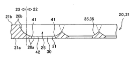
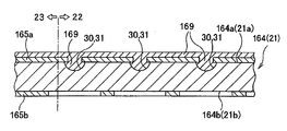
- FIG. 4 is an enlarged plan view showing the effective region 22 from the second surface 20b side of the vapor deposition mask 20 manufactured by the etching process.
- the plurality of through holes 25 formed in each effective region 22 are arranged at predetermined pitches along two directions orthogonal to each other in the effective region 22. Yes.
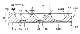
- An example of the through hole 25 will be described in more detail with reference mainly to FIGS. 5 to 7 are cross-sectional views along the AA direction, the BB direction, and the CC direction, respectively, of the effective region 22 of FIG.
- the boundary line between the effective area 22 and the surrounding area 23 shown in FIGS. 5 to 7 is an example, and the position of this boundary line is arbitrary.
- this boundary line may be arranged in a region where the second recess 35 is not formed (left side of the leftmost second recess 35 in FIG. 5).
- the plurality of through holes 25 extend along the normal direction N of the vapor deposition mask 20 from the first surface 20 a on one side along the normal direction N of the vapor deposition mask 20. It penetrates to the second surface 20b on the other side.
- the first recess 30 (or the first opening 30) is etched on the first surface 21a of the metal plate 21 on one side in the normal direction N of the vapor deposition mask 20.
- the second recess 35 (or the second opening 35) is formed on the second surface 21b of the metal plate 21 which is the other side in the normal direction N of the vapor deposition mask 20.
- the 1st recessed part 30 is connected to the 2nd recessed part 35, and is formed so that the 2nd recessed part 35 and the 1st recessed part 30 may mutually communicate by this.
- the through hole 25 is configured by a second recess 35 and a first recess 30 connected to the second recess 35.
- the plate of the vapor deposition mask 20 at each position along the normal direction N of the vapor deposition mask 20 from the second surface 20b side of the vapor deposition mask 20 toward the first surface 20a side.
- the opening area of each second recess 35 in the cross section along the plane is gradually reduced.
- the opening area of each first recess 30 in the cross section along the plate surface of the vapor deposition mask 20 at each position along the normal direction N of the vapor deposition mask 20 is from the first surface 20a side of the vapor deposition mask 20. It gradually becomes smaller toward the second surface 20b.
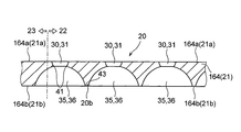
- the wall surface 31 of the first recess 30 and the wall surface 36 of the second recess 35 are connected via a circumferential connecting portion 41.
- the connection portion 41 the wall surface 31 of the first recess 30 inclined with respect to the normal direction N of the vapor deposition mask 20 and the wall surface 36 of the second recess 35 inclined with respect to the normal direction N of the vapor deposition mask 20 merge. It is defined by the ridgeline of the overhanging part.
- the connection part 41 defines the penetration part 42 with which the opening area of the through-hole 25 becomes the minimum in the planar view of the vapor deposition mask 20.
- two adjacent through holes 25 are formed on the other surface along the normal direction N of the vapor deposition mask 20, that is, on the first surface 20 a of the vapor deposition mask 20. They are separated from each other along the plate surface of the mask 20. That is, when the metal plate 21 is etched from the side of the first surface 21a of the metal plate 21 corresponding to the first surface 20a of the vapor deposition mask 20 as in the manufacturing method described later, the first recess 30 is produced. The first surface 21 a of the metal plate 21 remains between two adjacent first recesses 30.
- two adjacent second concave portions on one side along the normal direction N of the vapor deposition mask 20, that is, on the second surface 20 b side of the vapor deposition mask 20. 35 may be separated from each other along the plate surface of the vapor deposition mask 20. That is, the second surface 21b of the metal plate 21 may remain between two adjacent second recesses 35.
- the portion of the effective area 22 of the second surface 21 b of the metal plate 21 that remains without being etched is also referred to as a top portion 43.
- the vapor deposition mask 20 is manufactured so that the width ⁇ of the top portion 43 does not become excessively large.
- the width ⁇ of the top part 43 is preferably 2 ⁇ m or less.
- the width ⁇ of the top portion 43 generally varies depending on the direction in which the vapor deposition mask 20 is cut.
- the widths ⁇ of the top portions 43 shown in FIGS. 5 and 7 may be different from each other.
- the vapor deposition mask 20 may be configured such that the width ⁇ of the top portion 43 is 2 ⁇ m or less when the vapor deposition mask 20 is cut in any direction.
- etching may be performed so that two adjacent second recesses 35 are connected. That is, a place where the second surface 21b of the metal plate 21 does not remain may exist between two adjacent second recesses 35. Although not shown, the etching may be performed so that two adjacent second recesses 35 are connected over the entire area of the second surface 21b.
- the first surface 20 a of the vapor deposition mask 20 faces the organic EL substrate 92 as shown by a two-dot chain line in FIG. 5.
- the second surface 20 b of the vapor deposition mask 20 is located on the crucible 94 side that holds the vapor deposition material 98. Therefore, the vapor deposition material 98 adheres to the organic EL substrate 92 through the second recess 35 whose opening area is gradually reduced.
- FIG. 1 the first surface 20 a of the vapor deposition mask 20 faces the organic EL substrate 92 as shown by a two-dot chain line in FIG. 5.
- the second surface 20 b of the vapor deposition mask 20 is located on the crucible 94 side that holds the vapor deposition material 98. Therefore, the vapor deposition material 98 adheres to the organic EL substrate 92 through the second recess 35 whose opening area is gradually reduced.
- the deposition material 98 moves along the normal direction N of the organic EL substrate 92 from the crucible 94 toward the organic EL substrate 92 as indicated by an arrow from the second surface 20 b side to the first surface 20 a.
- the organic EL substrate 92 may move in a direction greatly inclined with respect to the normal direction N of the organic EL substrate 92.
- the thickness T0 of the vapor deposition mask 20 can be reduced, thereby reducing the height of the wall surface 36 of the second recess 35 and the wall surface 31 of the first recess 30. It is considered preferable. That is, it can be said that it is preferable to use the metal plate 21 with the smallest possible thickness within the range in which the strength of the vapor deposition mask 20 can be secured as the metal plate 21 for constituting the vapor deposition mask 20.
- the thickness T0 of the vapor deposition mask 20 is preferably set to 85 ⁇ m or less, for example, 5 ⁇ m or more and 85 ⁇ m or less.
- the thickness T0 is set to 80 ⁇ m or less, for example, 10 ⁇ m to 80 ⁇ m, or 20 ⁇ m to 80 ⁇ m.
- the thickness T0 of the vapor deposition mask 20 may be set to 40 ⁇ m or less, for example, 10 to 40 ⁇ m or 20 to 40 ⁇ m.
- the thickness T0 is the thickness of the surrounding region 23, that is, the thickness of the portion of the vapor deposition mask 20 where the first recess 30 and the second recess 35 are not formed. Therefore, it can be said that the thickness T0 is the thickness of the metal plate 21.
- a straight line L ⁇ b> 1 that passes through the connection portion 41, which is a portion having the minimum opening area of the through hole 25, and another arbitrary position of the wall surface 36 of the second recess 35 is a normal direction of the deposition mask 20.
- the minimum angle made with respect to N is represented by the symbol ⁇ 1. That is, similarly to the case shown in FIG. 21 described later, this is a path of the vapor deposition material 98 passing through the end 38 of the through hole 25 (second concave portion 35) on the second surface 20b side of the vapor deposition mask 20, and the organic EL substrate.
- a path that forms an angle ⁇ ⁇ b> 1 with respect to the normal direction N of the vapor deposition mask 20 is represented by a symbol L ⁇ b> 1.
- L ⁇ b> 1 In order to make the vapor deposition material 98 moving obliquely reach the organic EL substrate 92 as much as possible without reaching the wall surface 36, it is advantageous to increase the angle ⁇ 1.
- symbol ⁇ represents the width of a portion (hereinafter also referred to as a rib portion) of the effective region 22 of the first surface 21 a of the metal plate 21 that remains without being etched.
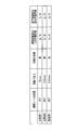
- the width ⁇ of the rib part and the dimension r2 of the through part 42 are appropriately determined according to the dimension of the organic EL display device and the number of display pixels.
- Table 1 shows an example of the number of display pixels and the value of the rib portion width ⁇ and the dimension r2 of the through portion 42 according to the number of display pixels in a 5-inch organic EL display device.
- the vapor deposition mask 20 according to the present embodiment is particularly effective when an organic EL display device having a pixel density of 450 ppi or more is manufactured.
- an example of the dimension of the vapor deposition mask 20 for producing such an organic EL display device with a high pixel density will be described.
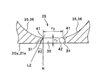
- FIG. 8 is an enlarged cross-sectional view of the through hole 25 of the vapor deposition mask 20 shown in FIG.
- the height of the 30 wall surfaces 31 is represented by the symbol r1.
- the dimension of the first recess 30 at the portion where the first recess 30 is connected to the second recess 35, that is, the dimension of the through portion 42 is represented by reference numeral r2.
- the angle formed by the straight line L2 connecting the connecting portion 41 and the leading edge of the first recess 30 on the first surface 21a of the metal plate 21 with respect to the normal direction N of the metal plate 21 is It is represented by the symbol ⁇ 2.
- the dimension r2 of the through portion 42 is preferably set to 10 or more and 60 ⁇ m or less. Accordingly, it is possible to provide the vapor deposition mask 20 that can produce an organic EL display device having a high pixel density.
- the height r1 of the wall surface 31 of the first recess 30 is set to 6 ⁇ m or less.
- the angle ⁇ 2 it is possible to suppress the vapor deposition material 98 that has come through at a large inclination angle and passed through the through portion 42 from adhering to the organic EL substrate 92. It can suppress that the vapor deposition material 98 adheres to a part outside the part which overlaps the penetration part 42 among these. That is, reducing the angle ⁇ 2 leads to suppression of variations in the area and thickness of the vapor deposition material 98 attached to the organic EL substrate 92. From such a viewpoint, for example, the through hole 25 is formed such that the angle ⁇ 2 is 45 degrees or less. In FIG.
- the dimension of the first recess 30 in the first surface 21a that is, the opening dimension of the through hole 25 in the first surface 21a is larger than the dimension r2 of the first recess 30 in the connection part 41.
- An example is shown. That is, the example in which the value of the angle ⁇ 2 is a positive value is shown.
- the dimension r2 of the first recess 30 in the connection part 41 may be larger than the dimension of the first recess 30 in the first surface 21a. That is, the value of the angle ⁇ 2 may be a negative value.
- Metal plate manufacturing method First, the manufacturing method of the metal plate used in order to manufacture a vapor deposition mask is demonstrated.
- a base material 155 made of an iron alloy containing nickel is prepared, and this base material 155 is directed to a rolling device 156 including a pair of rolling rolls 156a and 156b, and the direction indicated by the arrows. Convey along.
- the base material 155 that has reached between the pair of rolling rolls 156a and 156b is rolled by the pair of rolling rolls 156a and 156b.
- the base material 155 is reduced in thickness and stretched along the conveying direction. It is.
- a plate material 164X having a thickness t0 can be obtained.
- the wound body 162 may be formed by winding the plate material 164 ⁇ / b> X around the core 161.
- the specific value of the thickness t0 is preferably 5 ⁇ m or more and 85 ⁇ m or less as described above.
- FIG. 9 is only what shows the outline of a rolling process, and the concrete structure and procedure for implementing a rolling process are not specifically limited.
- the rolling process includes a hot rolling process in which the base material is processed at a temperature equal to or higher than a temperature at which the crystal arrangement of the invar material constituting the base material 155 is changed, and a base material at a temperature below the temperature at which the crystal arrangement of the invar material is changed It may include a cold rolling process for processing.
- the direction when the base material 155 and the plate material 164X are passed between the pair of rolling rolls 156a and 156b is not limited to one direction. For example, in FIGS.
- the base material 155 and the plate material 164X are repeatedly passed between the pair of rolling rolls 156a and 156b in the direction from the left side to the right side in the drawing and from the right side to the left side in the drawing.
- the material 155 and the plate material 164X may be gradually rolled.
- the plate material 164X is annealed using an annealing device 157, whereby the long metal plate 164 is obtained.
- the annealing step may be performed while pulling the plate material 164X or the long metal plate 164 in the transport direction (longitudinal direction). That is, the annealing step may be performed as continuous annealing while being conveyed, not so-called batch-type annealing.
- the annealing step described above is performed in a non-reducing atmosphere or an inert gas atmosphere.
- the non-reducing atmosphere is an atmosphere that does not contain a reducing gas such as hydrogen. “Does not contain reducing gas” means that the concentration of reducing gas such as hydrogen is 4% or less.
- the inert gas atmosphere is an atmosphere in which 90% or more of inert gas such as argon gas, helium gas, and nitrogen gas exists.
- the thickness t0 is usually equal to the thickness T0 of the vapor deposition mask 20.
- FIG. 10 shows an example in which the annealing process is performed while pulling the long metal plate 164 in the longitudinal direction.
- the annealing process is not limited to this, and the long metal plate 164 includes the core 161.
- the annealing process is performed in a state where the long metal plate 164 is wound around the core 161, the long metal plate 164 may be wrinkled with a warp corresponding to the winding diameter of the wound body 162. . Therefore, depending on the winding diameter of the wound body 162 and the material constituting the base material 155, it is advantageous to perform the annealing step while pulling the long metal plate 164 in the longitudinal direction.
- both ends of the long metal plate 164 in the width direction are cut off over a predetermined range, thereby performing a cutting step of adjusting the width of the long metal plate 164 to a desired width. In this way, a long metal plate 164 having a desired thickness and width can be obtained.
- a method of manufacturing the vapor deposition mask 20 using the long metal plate 164 will be described mainly with reference to FIGS.
- a long metal plate 164 is supplied, a through hole 25 is formed in the long metal plate 164, and the long metal plate 164 is further cut. By doing so, the vapor deposition mask 20 which consists of the sheet-like metal plate 21 is obtained.
- the manufacturing method of the vapor deposition mask 20 the step of supplying a long metal plate 164 extending in a strip shape, and etching using a photolithography technique are performed on the long metal plate 164, and the long metal plate
- the first concave portion 30 is formed on the long metal plate 164 from the side of the first surface 164a on the side of the first surface 164a, and the long metal plate 164 is etched on the long metal plate 164 from the side of the second surface 164b. Forming the two recesses 35. And the 1st recessed part 30 and the 2nd recessed part 35 which were formed in the elongate metal plate 164 mutually communicate, and the through-hole 25 is produced in the elongate metal plate 164.
- the step of forming the first recess 30 is performed before the step of forming the second recess 35, and the step of forming the first recess 30 and the formation of the second recess 35 are performed.
- a step of sealing the manufactured first recess 30 is further provided between the steps. Details of each step will be described below.
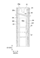
- FIG. 11 shows a manufacturing apparatus 160 for manufacturing the vapor deposition mask 20.
- a wound body 162 in which a long metal plate 164 is wound around a core 161 is prepared.
- a long metal plate 164 extending in a strip shape is supplied as shown in FIG.
- the long metal plate 164 is formed with a through-hole 25 to form a sheet metal plate 21 and a vapor deposition mask 20.
- etching apparatus etching means 170 by transport roller 172.
- etching apparatus etching means 170 by transport roller 172.
- a plurality of vapor deposition masks 20 are assigned in the width direction of the long metal plate 164. That is, the plurality of vapor deposition masks 20 are produced from regions that occupy predetermined positions of the long metal plate 164 in the longitudinal direction.
- the plurality of vapor deposition masks 20 are assigned to the long metal plate 164 so that the longitudinal direction D1 of the vapor deposition mask 20 coincides with the rolling direction of the long metal plate 164.
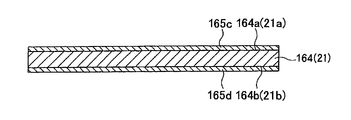
- resist films 165 c and 165 d containing a negative photosensitive resist material are formed on the first surface 164 a and the second surface 164 b of the long metal plate 164.
- a film on which a layer containing a photosensitive resist material such as an acrylic photo-curable resin is formed, a so-called dry film is formed on the first surface 164a of the long metal plate 164 and the first film 164a.
- a method of pasting on the two surfaces 164b is employed.
- exposure masks 168a and 168b that prevent light from being transmitted to the regions to be removed of the resist films 165c and 165d are prepared, and the exposure masks 168a and 168b are respectively formed on the resist films 165c and 165d as shown in FIG. To place.
- the exposure masks 168a and 168b for example, glass dry plates are used in which light is not transmitted to regions to be removed of the resist films 165c and 165d. Thereafter, the exposure masks 168a and 168b are sufficiently adhered to the resist films 165c and 165d by vacuum adhesion.
- the photosensitive resist material a positive type may be used. In this case, an exposure mask in which light is transmitted through a region to be removed of the resist film is used as the exposure mask.
- the developing step may include a resist heat treatment step for increasing the hardness of the resist films 165c and 165d or for causing the resist films 165c and 165d to adhere more firmly to the long metal plate 164.
- the resist heat treatment step is performed, for example, at 100 ° C. or higher and 400 ° C. or lower in an atmosphere of an inert gas such as argon gas, helium gas, or nitrogen gas.
- a first surface etching step of etching a region of the first surface 164 a of the long metal plate 164 that is not covered with the first resist pattern 165 a using the first etching solution carry out.
- the first etching solution is directed from the nozzle disposed on the side facing the first surface 164a of the transported long metal plate 164 toward the first surface 164a of the long metal plate 164 through the first resist pattern 165a. Is injected.
- erosion by the first etching solution proceeds in a region of the long metal plate 164 that is not covered by the first resist pattern 165a.
- first etching solution for example, a solution containing a ferric chloride solution and hydrochloric acid is used.
- the first recess 30 is covered with a resin 169 having resistance to the second etching solution used in the subsequent second surface etching step. That is, the first recess 30 is sealed with the resin 169 having resistance to the second etching solution.
- a film of resin 169 is formed so as to cover not only the formed first recess 30 but also the first surface 164a (first resist pattern 165a).
- a region of the second surface 164 b of the long metal plate 164 that is not covered with the second resist pattern 165 b is etched to form a second recess 35 in the second surface 164 b.
- a two-sided etching process is performed.
- the second surface etching process is performed until the first recess 30 and the second recess 35 communicate with each other, thereby forming the through hole 25.
- the second etching solution for example, a solution containing a ferric chloride solution and hydrochloric acid is used in the same manner as the first etching solution.
- the erosion by the second etching solution is performed in the portion of the long metal plate 164 that is in contact with the second etching solution. Therefore, the erosion does not proceed only in the normal direction N (thickness direction) of the long metal plate 164 but also proceeds in the direction along the plate surface of the long metal plate 164.
- the two second recesses 35 respectively formed at positions facing two adjacent holes 166a of the second resist pattern 165b are positioned between the two holes 166a. It ends before joining at the back side of the bridge portion 167a. Thereby, as shown in FIG. 18, the above-described top portion 43 can be left on the second surface 164 b of the long metal plate 164.
- the resin 169 is removed from the long metal plate 164.
- the resin 169 can be removed by using, for example, an alkaline stripping solution.
- an alkaline stripping solution is used, the resist patterns 165a and 165b are removed simultaneously with the resin 169, as shown in FIG. Note that after removing the resin 169, the resist patterns 165a and 165b may be removed separately from the resin 169 by using a remover different from the remover for removing the resin 169.
- the long metal plate 164 in which a large number of through-holes 25 are formed in this way is conveyed to a cutting device (cutting means) 173 by conveyance rollers 172 and 172 that rotate while the long metal plate 164 is held. Is done.
- the supply core 161 described above is rotated via the tension (tensile stress) acting on the long metal plate 164 by the rotation of the transport rollers 172 and 172, and the long metal plate 164 is supplied from the wound body 162. It is like that.
- the long metal plate 164 in which a large number of through-holes 25 are formed is cut into a predetermined length and width by a cutting device (cutting means) 173, whereby a sheet-like metal in which a large number of through-holes 25 are formed.
- a plate 21, that is, a vapor deposition mask 20, is obtained.
- the vapor deposition mask 20 can also be manufactured using a plating process. Then, the vapor deposition mask 20 manufactured by the plating process is demonstrated below. Here, first, the shape of the through hole 25 and the surrounding portion when the vapor deposition mask 20 is formed by plating will be described.
- FIG. 20 is an enlarged plan view showing the effective region 22 from the first surface 20a side of the vapor deposition mask 20 manufactured by plating.
- the plurality of through holes 25 formed in each effective region 22 are arranged at predetermined pitches along two directions orthogonal to each other in the effective region 22. Yes.
- An example of the through hole 25 will be described in detail with reference mainly to FIG.
- FIG. 21 is a cross-sectional view of the effective area 22 of FIG. 20 viewed from the DD direction.
- the vapor deposition mask 20 includes a first metal layer 32 that forms the first surface 20a, a second metal layer 37 that is provided on the first metal layer 32 and forms the second surface 20b, Is provided.
- the second metal layer 37 is disposed on the frame 15 (see FIG. 1 and the like) described above.
- the first metal layer 32 is provided with a first opening 30 in a predetermined pattern
- the second metal layer 37 is provided with a second opening 35 in a predetermined pattern.
- the first opening 30 and the second opening 35 communicate with each other, whereby the through hole 25 extending from the first surface 20a of the vapor deposition mask 20 to the second surface 20b is configured.
- the first opening 30 and the second opening 35 constituting the through hole 25 may have a substantially polygonal shape in plan view.
- the first opening 30 and the second opening 35 have a substantially square shape, more specifically, a substantially square shape.
- the first opening 30 and the second opening 35 may have other substantially polygonal shapes such as a substantially hexagonal shape and a substantially octagonal shape.
- the “substantially polygonal shape” is a concept including a shape in which corners of a polygon are rounded.
- the first opening 30 and the second opening 35 may be circular.
- the shape of the 1st opening part 30 and the shape of the 2nd opening part 35 do not need to be similar.
- reference numeral 41 represents a connection portion where the first metal layer 32 and the second metal layer 37 are connected.
- Reference sign S ⁇ b> 0 represents the dimension of the through hole 25 in the connection portion 41 between the first metal layer 32 and the second metal layer 37.
- FIG. 21 shows an example in which the first metal layer 32 and the second metal layer 37 are in contact with each other, but the present invention is not limited to this.
- Other layers may be interposed between the two layers.
- a catalyst layer for promoting precipitation of the second metal layer 37 on the first metal layer 32 may be provided between the first metal layer 32 and the second metal layer 37.
- FIG. 22 is an enlarged view showing a part of the first metal layer 32 and the second metal layer 37 of FIG.
- the width M2 of the second metal layer 37 on the second surface 20b of the vapor deposition mask 20 is smaller than the width M1 of the first metal layer 32 on the first surface 20a of the vapor deposition mask 20.
- the opening dimension S2 of the through hole 25 (second opening 35) in the second surface 20b is larger than the opening dimension S1 of the through hole 25 (first opening 30) in the first surface 20a.
- the vapor deposition material 98 flying from the second surface 20 b side of the vapor deposition mask 20 adheres to the organic EL substrate 92 through the second opening 35 and the first opening 30 of the through hole 25 in order.
- a region of the organic EL substrate 92 to which the vapor deposition material 98 adheres is mainly determined by the opening size S1 and the opening shape of the through hole 25 in the first surface 20a. 21 and 22, the vapor deposition material 98 is directed from the crucible 94 toward the organic EL substrate 92 in the normal direction N of the vapor deposition mask 20 as indicated by an arrow L1 from the second surface 20b side to the first surface 20a.
- the movement may occur in a direction greatly inclined.
- the opening dimension S2 of the through hole 25 in the second surface 20b is the same as the opening dimension S1 of the through hole 25 in the first surface 20a, it is greatly inclined with respect to the normal direction N of the vapor deposition mask 20.
- Most of the vapor deposition material 98 that moves in the direction reaches the second surface 20b (the upper surface of the second metal layer 37 in FIG. 21) of the vapor deposition mask 20 before reaching the organic EL substrate 92 through the through hole 25.
- adhering to the wall surface 36 of the second opening 35 of the through-hole 25 it adheres.
- the vapor deposition material 98 which cannot pass the through-hole 25 will increase. Therefore, in order to increase the utilization efficiency of the vapor deposition material 98, it can be said that it is preferable to increase the opening dimension S2 of the second opening 35, that is, to reduce the width M2 of the second metal layer 37.
- the minimum angle formed by the straight line L1 in contact with the wall surface 36 of the second metal layer 37 and the wall surface 31 of the first metal layer 32 with respect to the normal direction N of the vapor deposition mask 20 is represented by reference sign ⁇ 1.
- the angle ⁇ 1 is preferably set to 45 ° or more.
- the width M2 of the second metal layer 37 For increasing the angle ⁇ 1, it is effective to reduce the width M2 of the second metal layer 37 compared to the width M1 of the first metal layer 32. As is clear from the figure, it is also effective to reduce the thickness T1 of the first metal layer 32 and the thickness T2 of the second metal layer 37 in increasing the angle ⁇ 1. Note that if the width M2 of the second metal layer 37, the thickness T1 of the first metal layer 32, and the thickness T2 of the second metal layer 37 are excessively reduced, the strength of the vapor deposition mask 20 is lowered, and therefore, during transportation. It is conceivable that the vapor deposition mask 20 is damaged during use.
- the vapor deposition mask 20 is damaged due to the tensile stress applied to the vapor deposition mask 20 when the vapor deposition mask 20 is stretched on the frame 15.
- the dimensions of the first metal layer 32 and the second metal layer 37 are preferably set in the following ranges.
- the above-mentioned angle ⁇ 1 can be set to 45 ° or more, for example.
- the width M1 of the first metal layer 32 is 5 ⁇ m or more and 25 ⁇ m or less.
- the width M2 of the second metal layer 37 is 2 ⁇ m or more and 20 ⁇ m or less.
- the thickness T0 of the vapor deposition mask 20 is 3 ⁇ m or more and 50 ⁇ m or less, more preferably 3 ⁇ m or more.
- the thickness T0 of the vapor deposition mask 20 is the same in the effective region 22 and the surrounding region 23. is there.
- the above-described opening dimensions S0, S1, and S2 are appropriately set in consideration of the pixel density of the organic EL display device and the desired value of the above-described angle ⁇ 1.
- the opening dimension S0 of the through hole 25 in the connection portion 41 can be set to 15 ⁇ m or more and 60 ⁇ m or less.
- the opening dimension S1 of the first opening 30 on the first surface 20a is set to 10 ⁇ m or more and 50 ⁇ m or less
- the opening dimension S2 of the second opening 35 on the second surface 20b is set to 15 ⁇ m or more and 60 ⁇ m or less. Can be done.
- a recess 34 may be formed on the first surface 20 a of the vapor deposition mask 20 constituted by the first metal layer 32.
- the recess 34 is formed corresponding to a conductive pattern 52 of the pattern substrate 50 described later when the vapor deposition mask 20 is manufactured by plating.
- the depth D of the recess 34 is, for example, not less than 50 nm and not more than 500 nm.
- the outer edge 34 e of the recess 34 formed in the first metal layer 32 is located between the end 33 of the first metal layer 32 and the connection portion 41.
- (Method for manufacturing vapor deposition mask) 23 to 26 are views for explaining a method of manufacturing the vapor deposition mask 20.
- the pattern substrate 50 includes a base material 51 having insulating properties and a conductive pattern 52 formed on the base material 51.
- the conductive pattern 52 has a pattern corresponding to the first metal layer 32.
- the pattern substrate 50 may be subjected to a mold release process.
- a first plating process is performed in which the first plating solution is supplied onto the substrate 51 on which the conductive pattern 52 is formed to deposit the first metal layer 32 on the conductive pattern 52.
- the base material 51 on which the conductive pattern 52 is formed is immersed in a plating tank filled with the first plating solution.
- the first metal layer 32 in which the first openings 30 are provided in a predetermined pattern can be obtained on the pattern substrate 50.
- the first metal layer 32 has not only a portion overlapping the conductive pattern 52 when viewed along the normal direction of the base material 51, but also a conductive pattern as shown in FIG. It can also be formed in a portion that does not overlap with 52. This is because the first metal layer 32 is further deposited on the surface of the first metal layer 32 deposited on the portion overlapping the end portion 54 of the conductive pattern 52. As a result, as shown in FIG. 24, the end portion 33 of the first opening 30 can be located at a portion that does not overlap the conductive pattern 52 when viewed along the normal direction of the base material 51. . Further, the above-described depression 34 corresponding to the thickness of the conductive pattern 52 is formed on the surface of the first metal layer 32 on the side in contact with the conductive pattern 52.
- the specific method of the first plating process is not particularly limited.
- the first plating process may be performed as a so-called electrolytic plating process in which the first metal layer 32 is deposited on the conductive pattern 52 by passing a current through the conductive pattern 52.
- the first plating process may be an electroless plating process.
- the components of the first plating solution used are appropriately determined according to the characteristics of the first metal layer 32.
- a mixed solution of a solution containing a nickel compound and a solution containing an iron compound can be used as the first plating solution.
- a mixed solution of a solution containing nickel sulfamate or nickel bromide and a solution containing ferrous sulfamate can be used.
- Various additives may be contained in the plating solution.
- Additives include pH buffers such as boric acid, primary brighteners such as saccharin sodium, secondary brighteners such as butynediol, propargyl alcohol, coumarin, formalin and thiourea, antioxidants and stress relievers Can be used.
- the primary brightener may contain a sulfur component.
- a resist formation step is performed in which a resist pattern 55 is formed on the base material 51 and the first metal layer 32 with a predetermined gap 56 therebetween. As shown in FIG. 25, in the resist formation step, the first opening 30 of the first metal layer 32 is covered with the resist pattern 55 and the gap 56 of the resist pattern 55 is positioned on the first metal layer 32. To be implemented.
- a second plating process is performed in which the second plating solution is supplied to the gap 56 of the resist pattern 55 to deposit the second metal layer 37 on the first metal layer 32.
- the base material 51 on which the first metal layer 32 is formed is immersed in a plating tank filled with the second plating solution. Thereby, as shown in FIG. 26, the second metal layer 37 can be formed on the first metal layer 32.
- the specific method of the second plating process is not particularly limited.
- the second plating process may be performed as a so-called electrolytic plating process in which the second metal layer 37 is deposited on the first metal layer 32 by passing a current through the first metal layer 32.
- the second plating process may be an electroless plating process.
- the same plating solution as the first plating solution described above may be used.
- a plating solution different from the first plating solution may be used as the second plating solution.
- the composition of the first plating solution and the composition of the second plating solution are the same, the composition of the metal constituting the first metal layer 32 and the composition of the metal constituting the second metal layer 37 are also the same.
- resist removal process Thereafter, a resist removing process for removing the resist pattern 55 is performed.
- the resist pattern 55 can be peeled from the substrate 51, the first metal layer 32, and the second metal layer 37 by using an alkaline stripping solution.
- the vapor deposition mask 20 formed by the plating process is configured by the first metal layer 32 and the second metal layer 37 .
- the vapor deposition mask 20 formed by a plating process may be comprised with the single metal layer (not shown).
- a welding process is performed in which the vapor deposition mask 20 prepared as described above is welded to the frame 15 by etching or plating.
- the vapor deposition mask apparatus 10 provided with the vapor deposition mask 20 and the flame
- the obtained vapor deposition mask 20 is welded to the frame 15 in a stretched state, and the vapor deposition mask device 10 as shown in FIG. 3 is obtained.
- the vapor deposition mask packaging device 60a is a device for packaging the vapor deposition mask 20 described above, that is, the vapor deposition mask 20 having a plurality of through holes 25 and having the longitudinal direction D1.
- the vapor deposition mask package 60 mainly includes a vapor deposition mask 20 and a vapor deposition mask packaging device 60a in which the vapor deposition mask 20 is packed.
- FIG. 28 a cross section of the vapor deposition mask package 60 is shown.
- a cross section means the cross section which follows the width direction D2 (direction orthogonal to the longitudinal direction D1) of the vapor deposition mask 20 packed.
- 45 which will be described later, shows a longitudinal section of the vapor deposition mask package 60 in the sixth modified example.
- the longitudinal section means a section along the longitudinal direction D1 of the vapor deposition mask 20 to be packed.
- the vapor deposition mask package 60 includes a first base, a second base that is provided above the first base, and faces the first base, and a first base. And a vapor deposition mask laminated body 80 disposed between the first base portion and the second base portion.
- the first base may be a first substrate formed in a plate shape.
- the substrate is not limited to a plate-like member in which a pair of main surfaces provided on opposite sides are parallel to each other and are formed flat.
- the pair of main surfaces may be non-parallel, or one main surface may be formed non-flat.
- the second base may be a second substrate formed in a plate shape.
- the receiving portion 61 formed in a plate shape is taken as an example as an example of the first base portion, and the lid portion 62 formed in a plate shape as an example of the second base portion will be described below. To do.
- the vapor deposition mask laminated body 80 may have the plurality of vapor deposition masks 20 described above. Details of the vapor deposition mask laminate 80 will be described later.
- the above-described vapor deposition mask packaging device 60 a is a device for packaging the vapor deposition mask laminate 80 including the vapor deposition mask 20.
- the deposition mask packaging device 60a mainly includes a receiving portion 61, a lid portion 62, and a pair of spacers 64 described later. That is, the configuration of the vapor deposition mask packaging body 60a is obtained by removing the vapor deposition mask stacked body 80, the lid portion side insertion sheet 82 and the receiving portion side insertion sheet 83 described later from the vapor deposition mask packaging body 60.
- Each vapor deposition mask 20 of the vapor deposition mask laminate 80 is held by a receiving portion 61 and a lid portion 62.
- the receiving portion 61 and the lid portion 62 are formed separately and are bound by the binding portion.
- an elastic belt 63 will be described below as an example of a binding portion.
- the receiving portion 61 and the lid portion 62 are pressed against each other by the elastic force of the elastic belt 63.
- an example is shown in which the receiving portion 61 and the lid portion 62 are bound by two elastic belts 63, but if the receiving portion 61 and the lid portion 62 can be prevented from shifting from each other during transportation, etc.,
- the number of elastic belts 63 is arbitrary.
- the receiving portion 61 and the lid portion 62 may be configured by a single material sheet, or may be configured by laminating and adhering a plurality of material sheets (for example, plastic cardboard sheets such as polypropylene).
- a plastic corrugated sheet is preferable from the viewpoint of strength and mass, that is, it is lightweight despite having a desired strength, and a corrugated crossing interposed between a pair of liners and the liner. And a middle core having a surface.
- the corrugated ridges (or valleys) extending in the center of the corrugated cardboard sheets adjacent to each other are laminated so that they are orthogonal to each other.
- the corrugated cardboard sheet made of polypropylene include, for example, Sunply manufactured by Sumika Plustech, Dunplate manufactured by Ube Eximo, Single Cone, Twin Cone, Minadan manufactured by Sakai Chemical Industry, and the like.
- the receiving portion 61 and the lid portion 62 are antistatic coated in order to suppress the generation of static electricity. More specifically, the receiving portion 61 and the lid portion 62 may be coated with an antistatic agent, and an antistatic layer may be formed on both surfaces of the receiving portion 61 and the lid portion 62. In this case, it is possible to suppress charging of the receiving portion 61 and the lid portion 62, and it is possible to suppress adhesion of the vapor deposition mask 20 and insertion sheets 81, 82, and 83 to be described later due to electrostatic action during unpacking. Examples of such antistatic agents include surfactants, conductive polymers, carbon black, metals, and the like.
- the material of the receiving portion 61 may be a material in which a conductive layer or an antistatic layer is formed on the surface layer, or a material in which an antistatic agent is kneaded
- the material of the lid portion 62 may be a conductive layer or a surface layer.
- a material in which an antistatic layer is formed or a material in which an antistatic agent is kneaded may be used.
- the spacer 64 described later is preferably coated with an antistatic coating, or the material of the spacer 64 may be a material kneaded with an antistatic agent.
- the receiving portion 61 has a first facing surface 65 that faces the lid portion 62.
- the first facing surface 65 may be formed in a flat shape, and the vapor deposition mask laminated body 80 is placed on the first facing surface 65.
- the lid part 62 has a second facing surface 66 that faces the receiving part 61.
- the second facing surface 66 may be formed in a flat shape.
- the receiving portion 61 and the lid portion 62 overlap each other in plan view (described later).
- the dimension of the receiving part 61 and the cover part 62 in the longitudinal direction D1 of the vapor deposition mask 20 can be arbitrarily set according to the dimension in the longitudinal direction D1 of the vapor deposition mask 20, for example, the lower limit is 100 mm or more. It may be 300 mm or more, may be 500 mm or more, and may be 700 mm or more.
- the upper limit may be 1000 mm or less, 1500 mm or less, 2000 mm or less, or 3000 mm or less.
- the range may be determined by a combination of any one of the plurality of lower limit candidate values described above and any one of the plurality of upper limit candidate values described above.
- 100 mm or more and 1000 mm or less may be sufficient, 700 mm or more and 3000 mm or less may be sufficient, and 500 mm or more and 1500 mm or less may be sufficient.
- the range may be determined by a combination of any two of the plurality of lower limit candidate values described above.
- 100 mm or more and 700 mm or less may be sufficient, 300 mm or more and 500 mm or less may be sufficient, and 500 mm or more and 700 mm or less may be sufficient.
- the range may be determined by a combination of any two of the plurality of upper limit candidate values described above.
- the vapor deposition mask 20 which has a desired dimension in the longitudinal direction D1 can be accommodated by setting it as 100 mm or more.
- the vapor deposition mask packaging body 60 and the vapor deposition mask packaging device 60a during transportation and storage can be suppressed.
- the lower limit is 30 mm or more. It may be 50 mm or more, 100 mm or more, or 200 mm or more.
- the upper limit may be 300 mm or less, 500 mm or less, 800 mm or less, or 1000 mm or less.
- the range may be determined by a combination of any one of the plurality of lower limit candidate values described above and any one of the plurality of upper limit candidate values described above.
- 30 mm or more and 1000 mm or less may be sufficient, 50 mm or more and 800 mm or less may be sufficient, and 100 mm or more and 500 mm or less may be sufficient.
- the range may be determined by a combination of any two of the plurality of lower limit candidate values described above.
- 30 mm or more and 200 mm or less may be sufficient, 50 mm or more and 200 mm or less may be sufficient, and 100 mm or more and 200 mm or less may be sufficient.
- the range may be determined by a combination of any two of the plurality of upper limit candidate values described above.
- 300 mm or more and 1000 mm or less may be sufficient, 300 mm or more and 800 mm or less may be sufficient, and 500 mm or more and 800 mm or less may be sufficient.
- the thickness may be set to 30 mm or more, the vapor deposition mask 20 having a desired dimension in the width direction D2 can be accommodated.
- the vapor deposition mask packaging body 60 and the vapor deposition mask packaging device 60a during transportation or storage can be suppressed.
- the lower limit of the thickness of the receiving portion 61 may be 0.5 mm or more, 1.5 mm or more, or 5 mm or more.
- the upper limit may be 10 mm or less, 20 mm or less, or 40 mm or less.
- the range may be determined by a combination of any one of the plurality of lower limit candidate values described above and any one of the plurality of upper limit candidate values described above. For example, it may be 0.5 mm or more and 40 mm or less, 1.5 mm or more and 20 mm or less, or 5 mm or more and 10 mm or less.
- the range may be determined by a combination of any two of the plurality of lower limit candidate values described above.
- it may be 0.5 mm or more and 5 mm or less, 0.5 mm or more and 1.5 mm or less, or 1.5 mm or more and 5 mm or less.
- the range may be determined by a combination of any two of the plurality of upper limit candidate values described above.
- it may be 10 mm or more and 40 mm or less, 10 mm or more and 20 mm or less, or 20 mm or more and 40 mm or less.
- by setting the thickness to 0.5 mm or more deformation of the vapor deposition mask packaging body 60 and the vapor deposition mask packaging device 60a during transportation and storage can be suppressed.
- the thickness is preferably within the above-described range.
- the lower limit of the thickness of the lid 62 may be 0.5 mm or more, 1.5 mm or more, or 5 mm or more.
- the upper limit may be 10 mm or less, 20 mm or less, or 40 mm or less.
- the range may be determined by a combination of any one of the plurality of lower limit candidate values described above and any one of the plurality of upper limit candidate values described above. For example, it may be 0.5 mm or more and 40 mm or less, 1.5 mm or more and 20 mm or less, or 5 mm or more and 10 mm or less.
- the range may be determined by a combination of any two of the plurality of lower limit candidate values described above.
- it may be 0.5 mm or more and 5 mm or less, 0.5 mm or more and 1.5 mm or less, or 1.5 mm or more and 5 mm or less.
- the range may be determined by a combination of any two of the plurality of upper limit candidate values described above.
- it may be 10 mm or more and 40 mm or less, 10 mm or more and 20 mm or less, or 20 mm or more and 40 mm or less.
- by setting the thickness to 0.5 mm or more deformation of the vapor deposition mask packaging body 60 and the vapor deposition mask packaging device 60a during transportation and storage can be suppressed.
- the thickness is preferably within the above-described range.
- a pair of spacers 64 are interposed between the receiving portion 61 and the lid portion 62.
- the pair of spacers 64 are disposed on both sides in the width direction D ⁇ b> 2 of the vapor deposition mask 20, and an accommodation space 64 a of the vapor deposition mask stacked body 80 is defined between the pair of spacers 64.
- the accommodation space 64a has a longitudinal direction D3 along the longitudinal direction D1 of the deposition mask 20 to be accommodated.
- the spacer 64 extends in the longitudinal direction D1 of the vapor deposition mask 20 along the side edge 20f in the width direction D2 of the vapor deposition mask 20. It is restricted to move to.
- the spacer 64 is formed separately from the receiving portion 61 and the lid portion 62, and may be joined to the second facing surface 66 of the lid portion 62 with an adhesive or the like. However, the spacer 64 may be joined to the first facing surface 65 of the receiving portion 61.
- the material of the spacer 64 is not particularly limited as long as it can withstand the force applied when the receiving portion 61 and the lid portion 62 are bound by the elastic belt 63.
- it may be formed of a plastic material having a desired strength (for example, polyester, polycarbonate, polypropylene, polyacetal, polyoxymethylene, MC nylon, supramolecular polyethylene, epoxy, etc.).
- the hardness of the spacer 64 may be higher than the hardness of the receiving portion 61 and the lid portion 62. Thereby, rigidity can be increased with respect to the force in the vertical direction received by the vapor deposition mask package 60, and the vertical force applied to the vapor deposition mask laminate 80 can be suppressed.
- an adhesive for joining the spacer 64 to the lid portion 62 an adhesive using a material that suppresses shrinkage at the time of curing is preferable.
- a system adhesive or a modified silicone adhesive may be used.
- a non-woven fabric, paper, or a plastic film such as polyester may be used as the substrate, and an adhesive containing, for example, an acrylic resin may be used as the adhesive.
- the dimension of the spacer 64 in the longitudinal direction D ⁇ b> 1 of the vapor deposition mask 20 may be the same as that of the receiving part 61 and the lid part 62.
- the dimension of the spacer 64 in the width direction D2 of the vapor deposition mask 20 (corresponding to the width direction D4 in the accommodation space 64a) may be set so that the accommodation space 64a can be formed.
- the dimension along the width direction D4 of the accommodation space 64a can be arbitrarily set according to the vapor deposition mask 20 to be packed.
- the lower limit of the dimension along the width direction D2 of the vapor deposition mask 20 may be, for example, 10 mm or more, 20 mm or more, or 50 mm or more.
- the upper limit may be 100 mm or less, 500 mm or less, or 1000 mm or less.
- the range may be determined by a combination of any one of the plurality of lower limit candidate values described above and any one of the plurality of upper limit candidate values described above.
- 10 mm or more and 1000 mm or less may be sufficient, 20 mm or more and 500 mm or less may be sufficient, and 50 mm or more and 100 mm or less may be sufficient.
- the range may be determined by a combination of any two of the plurality of lower limit candidate values described above. For example, it may be 10 mm or more and 20 mm or less, 10 mm or more and 50 mm or less, or 20 mm or more and 50 mm or less.
- the range may be determined by a combination of any two of the plurality of upper limit candidate values described above. For example, 100 mm or more and 500 mm or less may be sufficient, 100 mm or more and 1000 mm or less may be sufficient, and 500 mm or more and 1000 mm or less may be sufficient.
- the lower limit may be 10 mm or more, 20 mm or more, or 50 mm or more.
- the upper limit may be 100 mm or less, 500 mm or less, or 1000 mm or less.
- the range may be determined by a combination of any one of the plurality of lower limit candidate values described above and any one of the plurality of upper limit candidate values described above.
- 10 mm or more and 1000 mm or less may be sufficient, 20 mm or more and 500 mm or less may be sufficient, and 50 mm or more and 100 mm or less may be sufficient.
- the range may be determined by a combination of any two of the plurality of lower limit candidate values described above. For example, it may be 10 mm or more and 20 mm or less, 10 mm or more and 50 mm or less, or 20 mm or more and 50 mm or less.
- the range may be determined by a combination of any two of the plurality of upper limit candidate values described above. For example, 100 mm or more and 500 mm or less may be sufficient, 100 mm or more and 1000 mm or less may be sufficient, and 500 mm or more and 1000 mm or less may be sufficient.
- the thickness is 10 mm or more
- various width dimensions of the vapor deposition mask 20 can be supported.
- the thickness is 10 mm or more
- various width dimensions of the vapor deposition mask 20 can be supported.
- the thickness is 1000 mm or less, it is possible to provide a gap between the vapor deposition mask 20 and the spacer 64 to avoid contact with the package when displaced in the width direction. Handleability can be improved.
- the lower limit of the thickness of the spacer 64 may be 1 mm or more, 5 mm or more, 10 mm or more, or 20 mm or more.
- the upper limit may be 30 mm or less, 40 mm or less, 60 mm or less, or 80 mm or less.
- the range may be determined by a combination of any one of the plurality of lower limit candidate values described above and any one of the plurality of upper limit candidate values described above. For example, it may be 1 mm or more and 80 mm or less, 5 mm or more and 60 mm or less, 10 mm or more and 40 mm or less, or 20 mm or more and 30 mm or less.
- the range may be determined by a combination of any two of the plurality of lower limit candidate values described above.
- it may be 1 mm or more and 20 mm or less, 5 mm or more and 10 mm or less, 1 mm or more and 10 mm or less, or 5 mm or more and 20 mm or less.
- the range may be determined by a combination of any two of the plurality of upper limit candidate values described above.
- it may be 30 mm or more and 80 mm or less, 40 mm or more and 60 mm or less, 30 mm or more and 60 mm or less, or 40 mm or more and 80 mm or less.
- the accommodation space 64a can be sufficiently secured even when the vapor deposition mask laminate 80 is accommodated.
- the weight applied to the lowermost vapor deposition mask 20 of the vapor deposition mask laminate 80 can be suppressed, and deformation of the vapor deposition mask 20 during transportation and storage can be suppressed.
- spacers may be arranged on both sides of the vapor deposition mask 20 in the longitudinal direction D1.
- the accommodation space 64a of the vapor deposition mask laminated body 80 is demarcated so as to be surrounded by the spacers, and restricts the movement of the insertion sheets 81, 82, 83 described later in the longitudinal direction D1. ing.
- the lid 62 has a convex portion 67 disposed on at least one of the both end portions 20e in the longitudinal direction D1 of the vapor deposition mask 20 in plan view.
- the convex portion 67 is arranged at at least one of both end portions in the longitudinal direction D3 of the above-described accommodation space 64a defined by the pair of spacers 64 in plan view.
- FIG. 32 shows a cross section taken along line EE of FIG. 31
- the receiving portion 61 is arranged on the back side of the vapor deposition mask 20 on the paper surface
- the lid portion 62 is arranged on the near side of the paper surface.
- an example is shown in which the lid portion 62 has a pair of convex portions 67 arranged at both end portions 20e, but either one of the convex portions 67 is provided on the lid portion 62. It does not have to be.
- the convex portion 67 may not overlap with the through hole 25 through which the vapor deposition material 98 passes during vapor deposition in plan view.
- the convex portion 67 has an effective area in the longitudinal direction D1 of the vapor deposition mask 20 in a plan view (when viewed from a direction perpendicular to the first surface 20a or the second surface 20b of the vapor deposition mask 20). 22 on both sides. More specifically, each projection 67 is disposed at a position overlapping the corresponding end opening 24 of the vapor deposition mask 20 in plan view, and is disposed at the center in the width direction D2 of the vapor deposition mask 20.
- each convex part 67 does not protrude from the corresponding edge part opening part 24 in planar view. Moreover, each convex part 67 contains the lower surface 67a which contacts the cover part side insertion sheet
- the convex portion 67 is formed separately from the lid portion 62 and may be joined to the second facing surface 66 of the lid portion 62 with an adhesive or the like.
- the material of the convex portion 67 is not particularly limited, but may be made of plastic, rubber, sponge, or the like. The hardness of the convex portion 67 may be lower than the hardness of the receiving portion 61 and the lid portion 62.
- Such a convex part 67 may have a hardness of C / 3 or more and C / 60 or less, for example.
- the convex portion 67 can press and support the vapor deposition mask 20 via the lid side insertion sheet 82, and the vertical movement of the vapor deposition mask 20 during transportation can be achieved. It can be effectively suppressed.
- the hardness measurement of the convex part 67 mentioned above is a value by JISK7312 using the Asker rubber hardness meter C type
- the convex part 67 have 25% compression hardness (JIS K6400, D method) of 50 N or more.
- 25% compression hardness JIS K6400, D method
- the pressure applied to the vapor deposition mask 20 can be appropriately maintained.
- the planar dimension of the convex portion 67 can be arbitrarily set according to the size of the end opening 24 of the vapor deposition mask 20.
- the dimension of the convex part 67 in the longitudinal direction D1 of the vapor deposition mask 20 may be 5 mm or more, for example. By setting it to 5 mm or more, the vapor deposition mask 20 can be supported by the convex portion 67 and the receiving portion 61, and the vertical movement of the vapor deposition mask 20 can be suppressed during transportation, and the first direction D1 and the first direction Movement in a plane including the two directions D2 can be suppressed.
- the lower limit of the thickness of the convex portion 67 may be 0.1 mm or more, 1 mm or more, 5 mm or more, or 10 mm or more.
- the upper limit may be 20 mm or less, 30 mm or less, 40 mm or less, or 60 mm or less.
- the range may be determined by a combination of any one of the plurality of lower limit candidate values described above and any one of the plurality of upper limit candidate values described above. For example, it may be 0.1 mm or more and 60 mm or less, 1 mm or more and 40 mm or less, 5 mm or more and 30 mm or less, or 10 mm or more and 20 mm or less.
- the range may be determined by a combination of any two of the plurality of lower limit candidate values described above. For example, it may be 0.1 mm or more and 10 mm or less, 1 mm or more and 5 mm or less, 0.1 mm or more and 5 mm or less, or 1 mm or more and 10 mm or less.
- the range may be determined by a combination of any two of the plurality of upper limit candidate values described above. For example, 20 mm or more and 60 mm or less may be sufficient, 30 mm or more and 40 mm or less may be sufficient, 20 mm or more and 40 mm or less may be sufficient, and 30 mm or more and 60 mm or less may be sufficient.
- the vapor deposition mask 20 can be supported by the convex part 67 and the receiving part 61, and the vertical movement of the vapor deposition mask 20 can be suppressed during transportation.
- the convex portion 67 from excessively pressing the region overlapping the end opening 24 of the lid side insertion sheet 82, and the vapor deposition mask 20 receives from the convex portion 67. Can weaken power.
- the vapor deposition mask laminate 80 includes a plurality of vapor deposition masks 20 stacked on each other and a plurality of third sheets laminated on the first surface 20 a and the second surface 20 b of the vapor deposition mask 20. And have.
- an intermediate insertion sheet 81 will be described as an example of the third sheet.
- a plurality of vapor deposition masks 20 and a plurality of intermediate insertion sheets 81 are alternately stacked, and the intermediate insertion sheets 81 are disposed between the vapor deposition masks 20 adjacent to each other.
- the lowermost layer and the uppermost layer of the vapor deposition mask laminate 80 are vapor deposition masks 20.
- the first surface 20a of the vapor deposition mask 20 that is neither the lowermost nor the uppermost layer is covered with an intermediate insertion sheet 81 facing the first surface 20a, and the second surface 20b faces the second surface 20b.
- the intermediate sheet 81 is covered. Accordingly, the insertion sheets 81 prevent the through holes 25 of one of the vapor deposition masks 20 adjacent to each other and the through holes 25 of the other vapor deposition mask 20 from being caught by each other and deformed.
- a first sheet is disposed between the vapor deposition mask laminate 80 and the lid 62.
- the lid side insertion sheet 82 will be described as an example of the first sheet.
- the lid side insertion sheet 82 faces the vapor deposition mask 20 constituting the uppermost stage of the vapor deposition mask laminate 80 and covers the vapor deposition mask 20. Thereby, deformation of the through hole 25 of the uppermost vapor deposition mask 20 is suppressed.
- a second sheet is disposed between the vapor deposition mask laminate 80 and the receiving portion 61.
- the receiving part side insertion sheet 83 will be described as an example of the second sheet.
- the receiving part side insertion sheet 83 faces the vapor deposition mask 20 constituting the lowermost stage of the vapor deposition mask laminate 80 and covers the vapor deposition mask 20. This suppresses deformation of the through hole 25 of the lowermost vapor deposition mask 20.
- the vapor deposition mask laminated body 80 is arrange
- the number of the lid part side insertion sheets 82 arranged between the vapor deposition mask laminated body 80 and the lid part 62 is arbitrary. That is, the number of the lid-side insertion sheets 82 may be set according to the thickness and the number of the vapor deposition masks 20 so that the dimension G of the gap 68 described later has a desired value.
- the number of the receiving part side insertion sheets 83 arranged between the vapor deposition mask laminated body 80 and the receiving part 61 is arbitrary. That is, the number of the receiving portion side insertion sheets 83 may be set according to the thickness and the number of the vapor deposition masks 20 so that the dimension G of the gap 68 described later falls within a desired range.
- the lower limit of the number of vapor deposition masks 20 constituting the vapor deposition mask laminate 80 may be 1 or more, 5 or more, 10 or more, and 15 or more. It may be.
- the upper limit may be 20 sheets or less, 25 sheets or less, 30 sheets or less, or 35 sheets or less.
- the range may be determined by a combination of any one of the plurality of lower limit candidate values described above and any one of the plurality of upper limit candidate values described above. For example, it may be 1 or more and 35 or less, 5 or more and 30 or less, 10 or more and 25 or less, or 15 or more and 20 or less.
- the range may be determined by a combination of any two of the plurality of lower limit candidate values described above.
- it may be 1 or more and 15 or less, 5 or more and 10 or less, 1 or more and 10 or less, or 5 or more and 15 or less.
- the range may be determined by a combination of any two of the plurality of upper limit candidate values described above. For example, 20 or more and 35 or less may be sufficient, 25 or more and 30 or less may be sufficient, 20 or more and 30 or less may be sufficient, and 25 or more and 35 or less may be sufficient.
- the lower limit of the thickness of the vapor deposition mask 20 may be 1 ⁇ m or more, 5 ⁇ m or more, 10 ⁇ m or more, or 20 ⁇ m or more.
- the upper limit may be 25 ⁇ m or less, 30 ⁇ m or less, 40 ⁇ m or less, or 60 ⁇ m or less.
- the range may be determined by a combination of any one of the plurality of lower limit candidate values described above and any one of the plurality of upper limit candidate values described above. For example, it may be 1 ⁇ m or more and 60 ⁇ m or less, 5 ⁇ m or more and 40 ⁇ m or less, 10 ⁇ m or more and 30 ⁇ m or less, or 20 ⁇ m or more and 25 ⁇ m or less.
- the range may be determined by a combination of any two of the plurality of lower limit candidate values described above. For example, it may be 1 ⁇ m or more and 20 ⁇ m or less, 5 ⁇ m or more and 10 ⁇ m or less, 1 ⁇ m or more and 10 ⁇ m or less, or 5 ⁇ m or more and 20 ⁇ m or less.
- the range may be determined by a combination of any two of the plurality of upper limit candidate values described above. For example, it may be 25 ⁇ m or more and 60 ⁇ m or less, 30 ⁇ m or more and 40 ⁇ m or less, 25 ⁇ m or more and 40 ⁇ m or less, or 30 ⁇ m or more and 60 ⁇ m or less.
- the lid side insertion sheet 82 and the receiving side insertion sheet 83 are arranged so that the dimension G of the gap 68 falls within a desired range.
- the number of sheets may be set.
- At least one lid side insertion sheet 82 is formed of PET film, the remaining lid side insertion sheet 82 is acrylic impregnated paper, You may form with other paper.
- at least one receiving part side insertion sheet 83 is formed of PET film, and the remaining receiving part side insertion sheets 83 are made of acrylic impregnated paper or other You may form with paper.
- There are different combinations of materials such as different materials (described later) and the same thickness, different materials (described later) and different thicknesses (thin and thick).
- An intermediate sheet 82 may be used.
- the longitudinal dimension (described later) and the width dimension of the lid-side insertion sheet 82 may be the same or different from each other, and the lid-side insertion sheet formed in various combinations. 82 may be used.
- the receiving-side insertion sheet 83 has the same material (described later) and the same thickness, or the same material (described later) and a different thickness (thin). Or different materials (described later) and the same thickness, or different materials (described later) and different thicknesses (thin or thick).
- the lid side insertion sheet 82 may be used.
- the longitudinal dimension (described later) and the width dimension of the receiving part side insertion sheet 83 may be the same or different from each other, and the receiving part side insertion sheet formed in various combinations. 83 may be used.
- Both surfaces of the intermediate insertion sheet 81, the lid part insertion sheet 82, and the receiving part insertion sheet 83 may be formed flat, and each of the insertion sheets 81, 82,. Except for the minute holes and irregularities that are sometimes formed, the holes and irregularities may not be formed.
- the insertion sheets 81, 82, to 83 suppress plastic deformation of the vapor deposition mask 20 when the individual vapor deposition mask 20 is taken out from the vapor deposition mask laminate 80.
- the vapor deposition mask 20 in the vapor deposition mask laminated body 80 has the same shape, it is preferable that the effective area 22 of each vapor deposition mask 20 is arranged so as to overlap when viewed along the lamination direction. Not limited to this.
- the number or shape of the effective regions 22 of each vapor deposition mask 20 may be different as long as the convex portion 67 of the lid 62 can be disposed at the end 20e of the vapor deposition mask 20 where the effective region 22 is not formed.
- the lower surface 67a of the convex part 67 of the lid part 62 is in contact with the upper surface of the lid part side insertion sheet 82, and the lid part side insertion sheet 82 is pressed against the convex part 67. Accordingly, the lid side insertion sheet 82 moves in the plane direction with respect to the convex portion 67 due to friction between the upper surface of the lid side insertion sheet 82 and the lower surface 67a of the convex portion 67 of the lid portion 62. Is suppressed.
- a gap 68 is formed between the lid portion-side insertion sheet 82 and the second facing surface 66 of the lid portion 62. That is, a gap 68 is formed between the lid-side insertion sheet 82 and the second facing surface 66 around the projection 67 including a region between the one projection 67 and the other projection 67. Yes. For this reason, this gap 68 is formed above the effective area of the vapor deposition mask 20.
- the gap 68 has a desired dimension G as a distance between the lid side insertion sheet 82 and the second facing surface 66. This dimension G may be equal to the height of the convex portion 67.
- the dimension G is smaller than the height of the convex portion 67 when not contracted. It may be.
- the height of the accommodation space 64a is demarcated by the spacer 64, even when the convex portion 67 contracts, the thickness or the number of the vapor deposition masks 20 of the vapor deposition mask laminate 80, or the insertion sheet 81, A gap 68 can be formed around the convex portion 67 by adjusting the thickness or number of the 82 and 83.
- the dimension G in this case may be the height when the convex portion 67 is contracted, or may be smaller than the height.
- the intermediate insertion sheet 81, the lid part insertion sheet 82, and the receiving part insertion sheet 83 are flexible enough to absorb the force applied to the vapor deposition mask 20 in a packed state and the shock applied during transportation. It is preferable to have. Moreover, it is preferable that each insertion sheet
- a PET (polyethylene terephthalate) film can be preferably used.
- the lower limit of the thickness of the film material may be 0.0010 mm or more, 0.0050 mm or more, 0.010 mm or more, or 0.050 mm or more.
- the upper limit may be 0.10 mm or less, 0.20 mm or less, 0.30 mm or less, or 0.50 mm or less.
- the range may be determined by a combination of any one of the plurality of lower limit candidate values described above and any one of the plurality of upper limit candidate values described above.
- it may be 0.0010 mm to 0.50 mm, 0.0050 mm to 0.30 mm, 0.010 mm to 0.20 mm, 0.050 mm to 0.000. It may be 10 mm or less.
- the range may be determined by a combination of any two of the plurality of lower limit candidate values described above. For example, 0.0010 mm or more and 0.050 mm or less may be sufficient, 0.0050 mm or more and 0.010 mm or less may be sufficient, 0.0010 mm or more and 0.010 mm or less may be sufficient, and 0.0050 mm or more and 0.0. It may be 050 mm or less.
- the range may be determined by a combination of any two of the plurality of upper limit candidate values described above.
- it may be 0.10 mm or more and 0.50 mm or less, may be 0.20 mm or more and 0.30 mm or less, may be 0.10 mm or more and 0.30 mm or less, and may be 0.20 mm or more and 0.20 mm or less. It may be 50 mm or less.
- the thickness of the insertion sheets 81, 82, 83 may be 0.010 mm or more, the uneven shape due to the through holes 25 of the vapor deposition mask 20 laminated on one surface of the insertion sheets 81, 82, 83 is Appearance on the other surface can be suppressed.
- each of the insertion sheets 81, 82, 83 may use a fiber material such as paper instead of the PET film.
- the interposition sheets 81, 82, 83 may be formed of acrylic impregnated paper. When acrylic impregnated paper is used, it is possible to suppress transfer of foreign matter generated from the fibers to the vapor deposition mask 20.
- each of the insertion sheets 81, 82, 83 has a vapor deposition mask over the entire periphery of the insertion sheets 81, 82, 83 when viewed along the stacking direction of the vapor deposition mask 20. It is preferable to have a dimension that can protrude from 20. In this Embodiment, the dimension (longitudinal direction full length) in the longitudinal direction D1 of the vapor deposition mask 20 of the interposition sheet 81, 82, 83 is larger than the full length longitudinal direction of the vapor deposition mask 20 (for example, 0.1 mm or more and 20 mm or less).
- the widthwise dimension of the vapor deposition mask 20 of the interposition sheets 81, 82, 83 is larger than the widthwise dimension of the vapor deposition mask 20 (for example, within a range of 0.1 mm to 20 mm). It is big).
- the insertion sheets 81, 82, and 83 can be protruded from the vapor deposition mask 20 over the entire circumference, and the vapor deposition masks 20 adjacent to each other are directly in contact with each other and overlap. Can be suppressed.
- the vapor deposition mask 20 when the longitudinal total length of the insertion sheets 81, 82, 83 is smaller than the total longitudinal length of the vapor deposition mask 20, the vapor deposition mask 20 on one side of the insertion sheets 81, 82, 83 and the other side. There is a possibility that the vapor deposition mask 20 directly contacts and overlaps and the through hole 25 is deformed. Further, when the width direction dimension of the interposition sheets 81, 82, 83 is smaller than the width direction dimension of the vapor deposition mask 20, the through hole 25 may be similarly deformed.
- the overall length in the longitudinal direction of the interposition sheets 81, 82, 83 is larger than the overall length in the longitudinal direction of the vapor deposition mask 20, and the widthwise dimension of the interposition sheets 81, 82, 83 Is larger than the dimension in the width direction of the vapor deposition mask 20, it is possible to suppress the vapor deposition masks 20 on both sides of the insertion sheets 81, 82, 83 from directly contacting and overlapping. For this reason, it can suppress effectively that the through-hole 25 deform
- Each of the insertion sheets 81, 82, 83 is preferably coated with antistatic coating in order to suppress the generation of static electricity. More specifically, the insertion sheets 81, 82, 83 may be coated with an antistatic agent, and antistatic layers may be formed on both surfaces of the insertion sheets 81, 82, 83. In this case, it can suppress that the insertion sheet
- antistatic agents include surfactants, conductive polymers, carbon black, metals, and the like.
- Examples of the interleaving sheets 81, 82, 83 include polyester synthetic paper K2323-188-690 mm manufactured by Toyobo Co., Ltd. sold under the trade name Krisper (registered trademark). Or you may make the material of the insertion sheet
- the lid side insertion sheet 82 is not attached to the convex portion 67 or the second facing surface 66 of the lid portion 62. Further, the receiving portion side insertion sheet 83 is not attached to the first facing surface 65 of the receiving portion 61. Thereby, at the time of thermal expansion, the lid portion side insertion sheet 82 and the receiving portion side insertion sheet 83 can smoothly be thermally expanded or contracted.
- the receiving part 61 and the lid part 62 sandwiching the vapor deposition mask laminated body 80 are sealed in a sealing bag 69.
- the inside of the sealing bag 69 is depressurized from the atmospheric pressure.
- a desiccant 70 (for example, silica gel) is accommodated in the sealing bag 69, and the desiccant 70 adsorbs moisture in the sealing bag 69 to maintain the dry state of the atmosphere in the sealing bag 69. Yes. This prevents the vapor deposition mask 20 from being altered by moisture.
- the sealing bag 69 is omitted.
- the vapor deposition mask package 60 may include an impact sensor 71 that detects an impact applied to the vapor deposition mask 20.
- the impact applied to the vapor deposition mask 20 during transportation can be confirmed after transportation. For this reason, when an impact of a predetermined value or more is applied during transportation, it is possible to estimate the possibility that the vapor deposition mask 20 is defective, and the transportation quality of the vapor deposition mask 20 can be improved.
- the sealed bag 69 is accommodated in a cardboard box 72, and the cardboard box 72 is packed in a wooden box 73. As shown in FIG. 28, it is preferable to install the impact sensor 71 in the wooden box 73, but the present invention is not limited to this.
- the impact sensor 71 for example, a shock watch label L-30 (green) manufactured by SHOCKWATCH Inc. can be suitably used.
- a lid portion 62 shown in FIG. 29 and a receiving portion 61 shown in FIG. 30 are prepared as the vapor deposition mask packaging device 60a.
- middle insertion sheet 81, the cover part side insertion sheet 82, and the receiving part side insertion sheet 83 are prepared.
- the receiving portion 61, the lid portion 62, the spacer 64, and the insertion sheets 81, 82, 83, etc. may be reused if it is considered that there is no problem in use such as alteration.
- the vapor deposition mask laminated body 80 mounted on the receiving part 61 is obtained.
- the receiving portion side insertion sheet 83 is placed on the receiving portion 61.
- the receiving portion-side insertion sheet 83 is disposed at a position that can be accommodated in the accommodating space 64 a defined by the pair of spacers 64 when the lid portion 62 is disposed on the receiving portion 61.
- the vapor deposition mask 20 is placed on the receiving portion side insertion sheet 83.
- the vapor deposition mask 20 is arranged so that the periphery of the receiving portion side insertion sheet 83 protrudes from the vapor deposition mask 20 over the entire circumference.
- the center of the deposition mask 20 in the longitudinal direction D1 is positioned at the center of the receiving portion 61 in the longitudinal direction, and the center of the deposition mask 20 in the width direction D2 is positioned at the center of the receiving portion 61 in the width direction.
- a mask 20 is disposed.
- the intermediate insertion sheet 81 is placed on the vapor deposition mask 20.
- the intermediate insertion sheet 81 is disposed so as to overlap the receiving portion side insertion sheet 83 in plan view.
- the plurality of vapor deposition masks 20 and the plurality of intermediate insertion sheets 81 are alternately stacked.
- seat 82 is mounted on the vapor deposition mask 20 laminated
- the lid side insertion sheet 82 is arranged so as to overlap the receiving part side insertion sheet 83 and the intermediate insertion sheet 81 in plan view.
- the lid 62 is disposed on the vapor deposition mask laminate 80. Accordingly, the receiving portion 61 and the lid portion 62 face each other, and the receiving portion 61 and the lid portion 62 are disposed on both sides in the vertical direction of the vapor deposition mask laminated body 80. In this case, the lower surface 67a of the convex portion 67 of the lid portion 62 is in contact with the lid side insertion sheet 82.
- the receiving portion 61 and the lid portion 62 are bound by the elastic belt 63. Accordingly, the receiving portion 61 and the lid portion 62 are pressed against each other by the elastic force of the elastic belt 63.
- the convex portion 67 presses the lid side insertion sheet 82.
- the vapor deposition mask 20 is transmitted with the pressing force from the convex portion 67 weakened. That is, in this Embodiment, as shown in FIG. 32, the convex part 67 is arrange
- the area overlapping the part opening 24 is not supported by the vapor deposition mask 20 below the area.
- the convex portion 67 presses the region overlapping the end opening 24 of the lid side insertion sheet 82, this region is bent.
- the lid part insertion sheet 82 presses each vapor deposition mask 20 arranged on the lower side through this bending deformation. In this way, a part of the pressing force of the convex portion 67 is absorbed by the lid-side insertion sheet 82, and the direct pressing force of the convex portion 67 to the vapor deposition mask 20 is suppressed. For this reason, the force which the vapor deposition mask 20 receives from the convex part 67 is weakened.
- the receiving portion 61 and the lid portion 62 are bound, the receiving portion 61 and the lid portion 62 are sealed together with the desiccant 70 in the sealing bag 69 as shown in FIG. Subsequently, the inside of the sealing bag 69 is evacuated. When the pressure in the sealing bag 69 decreases to a predetermined degree of vacuum, the opening of the sealing bag 69 is sealed.
- the receiving portion 61 and the lid portion 62 sealed with the sealing bag 69 are accommodated in a cardboard box 72 and the cardboard box 72 is packed in a wooden box 73 as shown in FIG. At this time, the impact sensor 71 is attached in the wooden box 73.
- the vapor deposition mask packaging body 60 by this Embodiment is obtained.
- each vapor deposition mask 20 receives the pressing force from the convex portion 67 via the lid side insertion sheet 82.
- both end portions in the longitudinal direction D1 of each vapor deposition mask 20 are supported by the convex portion 67 via the lid side insertion sheet 82, and the upward movement of each vapor deposition mask 20 is suppressed.
- the effective area 22 of each vapor deposition mask 20 may bend upward.
- each vapor deposition mask 20 is supported by the lid side insertion sheet 82, and an intermediate insertion sheet 81 is interposed between the vapor deposition masks 20.
- each vapor deposition mask 20 is supported by a receiving portion 61 having a flat first opposing surface 65 via a receiving portion side insertion sheet 83. Accordingly, the downward movement of each vapor deposition mask 20 is suppressed, and the effective region 22 of each vapor deposition mask 20 is also prevented from bending downward. For this reason, it can suppress that the vapor deposition mask 20 deforms plastically.
- the intervening sheet 81 is interposed between the vapor deposition masks 20 adjacent to each other, it is avoided that the vapor deposition masks 20 adjacent to each other are in direct contact with each other. For this reason, even if it is a case where the impact at the time of transportation is received, while it is suppressed that the vapor deposition masks 20 mesh in the effective area
- each vapor deposition mask 20 and each insertion sheet 81, 82, 83 are thermally expanded or contracted.
- the lid portion side insertion sheet 82 is interposed between the uppermost vapor deposition mask 20 and the convex portion 67 of the lid portion 62, and the lower vapor deposition mask 20 and the receiving portion are received.
- a receiving portion side insertion sheet 83 is interposed between the portions 61.
- Each of the vapor deposition masks 20 receives a force from the convex portion 67, but the force is weakened because the force is received via the lid side insertion sheet 82.
- a gap 68 is formed between the lid-side insertion sheet 82 and the second facing surface 66 of the lid 62 around the convex portion 67. For this reason, the vapor deposition mask 20 can smoothly be thermally expanded or contracted with respect to the receiving portion 61 and the lid portion 62. For this reason, generation
- the procedure reverse to the method for packing the vapor deposition mask 20 described above may be taken.
- the intermediate insertion sheet 81 is interposed between the vapor deposition masks 20 adjacent to each other, the vapor deposition mask 20 is prevented from being engaged with the vapor deposition mask 20 disposed below the vapor deposition mask 20.
- each vapor deposition mask 20 can be smoothly taken out from the vapor deposition mask laminated body 80.
- the handleability of the vapor deposition mask 20 can be improved.
- the lid portion-side insertion sheet 82 is disposed between the lid portion 62 and the vapor deposition mask 20, and is disposed at both ends in the longitudinal direction D1 of the vapor deposition mask 20 in plan view.
- the convex portion 67 presses the lid side insertion sheet 82.
- the vapor deposition mask 20 can be supported by the convex part 67 and the receiving part 61, and the vertical movement of the vapor deposition mask 20 can be suppressed during transportation.
- the vapor deposition mask 20 can be supported by the lid-side insertion sheet 82 disposed between the convex portion 67 and the vapor deposition mask 20. For this reason, the vertical movement of the vapor deposition mask 20 can be suppressed and the vapor deposition mask 20 can be prevented from bending upward. As a result, it is possible to suppress the vapor deposition mask 20 from being plastically deformed during transportation.
- the convex part 67 of the cover part 62 may press the cover part side insertion sheet
- the pressing force of the convex portion 67 is transmitted to the vapor deposition mask 20 via the lid side insertion sheet 82, so that the force received by the vapor deposition mask 20 from the convex portion 67 can be weakened.
- a gap 68 is formed between the lid-side insertion sheet 82 and the second facing surface 66 of the lid 62 around the convex portion 67. For this reason, even when the temperature is changed during transportation, the vapor deposition mask 20 can be smoothly expanded or contracted thermally, and the generation of thermal stress in the vapor deposition mask 20 can be suppressed.
- the vapor deposition mask 20 can suppress that the vapor deposition mask 20 carries out plastic deformation at the time of transport. Also, the vapor deposition mask 20 is smoothly expanded or thermally expanded with respect to the lid 62 in that the lid side insertion sheet 82 is disposed between the vapor deposition mask 20 and the convex portion 67 of the lid 62. Can be shrunk.
- the convex portion 67 of the lid portion 62 does not have to overlap the through hole 25 of the vapor deposition mask 20 in plan view. Thereby, it can avoid that the convex part 67 contacts the through-hole 25 formed in the effective area
- the convex portion 67 of the lid portion 62 may be disposed at a position overlapping the corresponding end opening portion 24 of the vapor deposition mask 20 in plan view.
- a part of the pressing force of the convex portion 67 is absorbed by the lid side insertion sheet 82, and the force received by the vapor deposition mask 20 from the convex portion 67 can be effectively weakened.
- the projection 67 does not protrude from the corresponding end opening 24, the force received by the vapor deposition mask 20 from the projection 67 can be further reduced. For this reason, the vapor deposition mask 20 at the time of a temperature change can be further thermally expanded or contracted more smoothly.
- the receiving portion side insertion sheet 83 may be disposed between the vapor deposition mask 20 and the receiving portion 61. Thereby, the vapor deposition mask 20 at the time of temperature change can be smoothly expanded or contracted with respect to the receiving portion 61.
- the intermediate insertion sheet 81 may be disposed between the vapor deposition masks 20 adjacent to each other in the vapor deposition mask laminate 80.
- the vapor deposition masks 20 adjacent to each other are in direct contact with each other and overlap.
- the vapor deposition mask 20 at the time of temperature change can be smoothly thermally expanded or contracted with respect to the other vapor deposition masks 20, and the plastic deformation of the vapor deposition mask 20 can be further suppressed.
- the hardness of the convex portion 67 may be lower than the hardness of the receiving portion 61 and the hardness of the lid portion 62. Thereby, the force which the vapor deposition mask 20 receives from the convex part 67 can be weakened. For this reason, even when the temperature changes during transportation, the vapor deposition mask 20 can be smoothly expanded or contracted thermally, and the generation of thermal stress on the vapor deposition mask 20 can be effectively suppressed. It is possible to suppress the plastic deformation of the vapor deposition mask 20 during transportation.
- the hardness of the spacer 64 may be higher than the hardness of the receiving portion 61 and the hardness of the lid portion 62. Thereby, the hardness of the spacer 64 can be increased, and the rigidity can be increased with respect to the vertical force received by the vapor deposition mask package 60. For this reason, it can suppress that the force of the vapor deposition mask 20 up-down direction is applied.
- the receiving part 61 and the lid part 62 sandwiching the vapor deposition mask laminate 80 are sealed in the sealing bag 69, and the desiccant 70 is stored in the sealing bag 69.
- a good example has been described.
- the present invention is not limited to this.
- the receiving portion 61 and the lid portion 62 that sandwich the vapor deposition mask laminated body 80 may be doubly sealed with two sealing bags 69a and 69b.
- the receiving part 61 and the lid part 62 sandwiching the vapor deposition mask laminate 80 are sealed with a first sealing bag 69a, and the first sealing bag 69a is sealed with a second sealing bag 69b. Further sealed.
- the inside of the first sealing bag 69a is depressurized from the atmospheric pressure. Further, the oxygen absorber 70a is accommodated in the first sealing bag 69a, and the oxygen absorber 70a absorbs oxygen remaining in the first sealing bag 69a, and the oxygen in the first sealing bag 69a is absorbed. Removes oxygen from the atmosphere. Thereby, it can suppress that the vapor deposition mask 20 degenerates with oxygen (for example, generation
- the inside of the second sealing bag 69b is depressurized from the atmospheric pressure. Further, the desiccant 70b is accommodated in the second sealed bag 69b, the moisture in the second sealed bag 69b is adsorbed by the desiccant 70b, and the dry state of the atmosphere in the second sealed bag 69b is obtained. Is maintained. Thereby, it can suppress that a water
- the second sealing bag 69b shows an example in which a pair of receiving portions 61 and a lid portion 62 sealed by the first sealing bag 69a are sealed. It is not limited to this. For example, a plurality of sets of receiving portions 61 and lid portions 62 each sealed with the first sealing bag 69a may be sealed with one second sealing bag 69b.
- the first sealing bag 69a is not limited to the storage of the oxygen scavenger 70a, and the desiccant 70b may be stored in place of or in addition to the oxygen absorber 70a.
- the second sealing bag 69b is not limited to storing the desiccant 70b, and the oxygen scavenger 70a may be stored instead of or in addition to the desiccant 70b.
- the first sealing bag 69a may be filled with an inert gas such as nitrogen gas or a non-reducing gas.
- the second sealing bag 69b may be filled with an inert gas such as nitrogen gas or a non-reducing gas.
- the concentration of inert gas such as nitrogen gas or non-reducing gas may be 85% or more, 90% or more, or 95% or more.
- each bag may contain at least one of an oxygen scavenger and a desiccant.
- an inert gas such as nitrogen gas or a non-reducing gas may be filled.
- the concentration of an inert gas such as nitrogen gas or a non-reducing gas may be 85% or more, 90% or more, or 95% or more.
- the desiccant 70 but also an oxygen scavenger may be accommodated in the sealed bag 69 shown in FIG. In this case, it is possible to further suppress the vapor deposition mask 20 from being altered by moisture and to further inhibit alteration from being caused by oxygen.
- the receiving part side insertion sheet 83, the vapor deposition mask laminated body 80, and the cover part side insertion sheet 82 are arrange
- FIG. 34 an auxiliary sheet (sometimes referred to as a pressing sheet) may be disposed between the receiving portion 61 and the receiving portion-side insertion sheet 83.
- a receiving portion side auxiliary sheet 88 will be described as an example.
- auxiliary sheet may be disposed between the lid side insertion sheet 82 and the lid 62.
- a lid side auxiliary sheet 89 will be described as an example of an auxiliary sheet (fifth sheet) between the lid side insertion sheet 82 and the lid 62.
- One of the receiving portion side auxiliary sheet 88 and the lid portion side auxiliary sheet 89 may not be used.
- Both surfaces of the receiving portion side auxiliary sheet 88 and the lid portion side auxiliary sheet 89 are formed in a flat shape, and the auxiliary sheets 88 and 89 are formed except for minute holes and irregularities formed during sheet manufacturing. In addition, holes and irregularities may not be formed.
- the lid side auxiliary sheet 89 presses the vapor deposition mask 20 by its own weight. Thereby, the vertical movement of the vapor deposition mask 20 can be suppressed during transportation.
- the receiving part side auxiliary sheet 88 is for adjusting the height of the accommodation space 64a.
- seat 88 and 89 has the intensity
- FIG. If it is a sheet
- each auxiliary sheet 88, 89 an arbitrary film material having an arbitrary thickness can be used for each auxiliary sheet 88, 89, but the thickness of each auxiliary sheet 88, 89 is thicker than the thickness of the insertion sheets 81, 82, 83. It may be thin or thin.
- a sheet made of polyethylene terephthalate (PET), polypropylene, polyethylene, polycarbonate, polystyrene or the like having a thickness of 10 ⁇ m to 300 ⁇ m can be used, and a 100 ⁇ m PET film is preferably used. be able to.
- the receiving part side auxiliary sheet 88 may have the same thickness as the cover part side auxiliary sheet 89 by having the same thickness.
- the PET film used for the auxiliary sheet may be a PET film containing a filler. Examples of filler materials include particles of inorganic oxides such as silica, calcium carbonate or titanium oxide, carbon black, metal particles, metal fibers, and the like.
- the auxiliary sheets 88 and 89 are preferably coated with an antistatic coating or kneaded with an antistatic agent, like the insertion sheets 81, 82 and 83. Moreover, you may serve as a filler and an antistatic agent by giving electroconductivity to the above-mentioned filler itself, or providing electroconductivity by covering a filler with a metal film or a metal oxide film.
- one intermediate insertion sheet 81 is disposed between the vapor deposition masks 20 adjacent to each other.
- the present invention is not limited to this, and two or more intermediate insertion sheets 81 may be arranged between the vapor deposition masks 20 adjacent to each other.
- two intermediate insertion sheets 81 are disposed between the vapor deposition masks 20 adjacent to each other.
- the vapor deposition mask 20 at the time of temperature change can be smoothly thermally expanded or contracted with respect to the other vapor deposition masks 20, and the plastic deformation of the vapor deposition mask 20 can be further suppressed.
- the point that two or more intermediate interposing sheets 81 are disposed between the vapor deposition masks 20 adjacent to each other can also be applied to the embodiment shown in FIG.
- seats 81 may be the same, or may differ.
- one intermediate insertion sheet 81 is formed of a PET film, and the other intermediate insertion sheet 81 is impregnated with acrylic. You may form with paper. Further, when three intermediate insertion sheets 81 are arranged between the vapor deposition masks 20 adjacent to each other, at least one intermediate insertion sheet 81 is formed of a PET film, and the remaining intermediate insertion sheets 81 are You may form with an acryl impregnation paper and other paper.
- intermediate insertion sheets 81 When a plurality of intermediate insertion sheets 81 are used, they are the same material (described later) and the same thickness, or the same material (described later) and different thicknesses (thin or thick).
- the longitudinal dimension (described later) and the width dimension of the intermediate insertion sheet 81 may be the same or different from each other, and the intermediate insertion sheet 81 formed in various combinations is used. Also good.
- each convex portion 67 is disposed at a position overlapping the corresponding end opening 24 of the vapor deposition mask 20 in plan view.
- the present invention is not limited to this, and the arrangement of the protrusions 67 is arbitrary as long as at least a part of the protrusions 67 is disposed at both ends in the longitudinal direction D1 of the vapor deposition mask 20.
- each convex portion 67 is disposed at a position where a part thereof overlaps the corresponding end opening 24. It extends to D 2 and is arranged to cross the end opening 24.
- each convex part 67 has a longitudinal direction along the width direction D2 of the vapor deposition mask 20, and the contact area between the vapor deposition mask 20 and the convex part 67 can be increased. For this reason, the support of the vapor deposition mask 20 can be stabilized. Moreover, the pressing force from the convex part 67 of the cover part 62 can be disperse
- the vapor deposition mask 20 can be smoothly expanded or contracted with respect to the receiving part 61 and the cover part 62 at the time of a temperature change. For this reason, generation
- the convex portion 67 may not overlap the through hole 25 through which the vapor deposition material 98 passes during vapor deposition. When the through-holes that are not intended to allow the vapor deposition material 98 to pass through are provided on both sides of the end opening 24 in the width direction D2, the convex portion 67 may overlap the through-hole. Good.
- each of the convex portions 67 is arranged at a position where a part thereof overlaps the corresponding end opening 24. It may extend in the longitudinal direction D1.
- the pair of convex portions 67 are integrated and formed continuously.
- the integrated convex portion 67 is formed from one end edge 20g (see FIG. 3) to the other end edge 20g along the longitudinal direction D1 of the vapor deposition mask 20.
- the pressing force from the convex part 67 of the cover part 62 can be disperse
- the vapor deposition mask 20 can be smoothly expanded or contracted with respect to the receiving part 61 and the cover part 62 at the time of a temperature change.
- the integrated convex portion 67 is arranged at the center in the width direction D2 of the vapor deposition mask 20.
- the force due to thermal expansion of the vapor deposition mask 20 can be released to the pair of side edges 20f of the vapor deposition mask 20 disposed far from the convex portion 67.
- the vapor deposition mask 20 can be thermally expanded smoothly, and plastic deformation of the vapor deposition mask 20 can be suppressed.
- the integrated convex portion 67 is disposed at the center of the vapor deposition mask 20 in the width direction D2
- the deformation of the vapor deposition mask 20 during thermal expansion can be made symmetric. For this reason, the plastic deformation of the vapor deposition mask 20 can be effectively suppressed.
- each protrusion 67 may not be integrated while extending in the longitudinal direction D1 of the vapor deposition mask 20.
- one or a plurality of other convex portions 67 may be formed between the pair of convex portions 67 arranged at both end portions 20e of the vapor deposition mask 20 in plan view, and may be intermittently arranged in one row.
- each convex portion 67 may be arranged in a region other than the effective region 22 (that is, the surrounding region 23).
- the first facing surface 65 of the receiving portion 61 includes a curved surface 84 that is curved so as to be convex toward the lid portion 62 side. May be.
- the curved shape of the curved surface 84 can be formed by an arbitrary curve such as a perfect circle or a part of an elliptical arc.
- the curved surface 84 is configured as a rigid body. On both sides of the vapor deposition mask 20 in the width direction D2 with respect to the curved surface 84, spacer contact surfaces 85 with which the spacers 64 contact are formed.
- the curved surface 84 includes a ridge line 86 extending from one edge 20g in the longitudinal direction D1 of the vapor deposition mask 20 to the other edge 20g in plan view.
- the ridge line 86 of the curved surface 84 extends from one edge of the accommodation space 64a defined by the pair of spacers 64 to the other edge in plan view.
- the ridge line 86 means a line connecting the highest point of the curved surface 84 (the point closest to the lid 62) in the cross section at each position in the longitudinal direction D1 of the vapor deposition mask 20.
- the vapor deposition mask 20 and the insertion sheets 81, 82, and 83 placed on the curved surface 84 are affected by the gravity to the curved surface 84. Bend along. That is, the vapor deposition mask 20 bends so that the pair of side edges 20 f of the vapor deposition mask 20 is disposed below the central portion in the width direction of the vapor deposition mask 20. For this reason, the movement of the vapor deposition mask 20 in the width direction D ⁇ b> 2 is restricted by the curved surface 84.
- the ridge line 86 is formed in parallel to the second facing surface 66 of the lid 62. That is, the minimum distance from the lid 62 to the curved surface 84 is constant over the longitudinal direction D1 of the vapor deposition mask 20.
- the ridge line 86 of the curved surface 84 extends through the vapor deposition mask 20 in the longitudinal direction D1.
- the bending shape of the vapor deposition mask 20 and each insertion sheet 81, 82, 83 is made uniform over the longitudinal direction D1 of the vapor deposition mask 20, and the vapor deposition mask 20 and each insertion sheet 81, 82, 83 are The bending to a two-dimensionally complicated shape is suppressed. For this reason, the plastic deformation of the vapor deposition mask 20 is suppressed.
- the lid portion 62 does not have the convex portion 67 as shown in FIG. 29, and the second facing surface 66 of the lid portion 62 is between the lid portion side insertion. It is in contact with the sheet 82 (particularly, the portion of the lid side insertion sheet 82 that overlaps the ridge line 86). Accordingly, the lid side insertion sheet 82 can be supported by the second facing surface 66. For this reason, even when a vertical force is applied to the vapor deposition mask 20 during transportation, the vertical movement of the vapor deposition mask 20 can be suppressed.
- the lid part side insertion sheet 82 covers the vapor deposition mask 20
- the vapor deposition mask 20 can be supported by the lid part side insertion sheet 82. For this reason, the vertical movement of the vapor deposition mask 20 can be suppressed and the vapor deposition mask 20 can be prevented from bending upward.
- the pressing force from the lid 62 can be dispersed by the lid-side insertion sheet 82 being supported by the second facing surface 66.
- the vapor deposition mask 20 can be smoothly expanded or contracted with respect to the receiving part 61 and the cover part 62 at the time of a temperature change. For this reason, generation
- the portion of the lid part side interposing sheet 82 that overlaps the ridge line 86 is disposed at the center of the vapor deposition mask 20 in the width direction D2.
- the force due to the thermal expansion of the vapor deposition mask 20 can be released to the pair of side edges 20f of the vapor deposition mask 20 disposed far from the ridge line 86.
- the vapor deposition mask 20 can be thermally expanded smoothly, and plastic deformation of the vapor deposition mask 20 can be suppressed.
- the ridge line 86 is disposed at the center of the vapor deposition mask 20 in the width direction D2
- the deformation of the vapor deposition mask 20 during thermal expansion can be made symmetric. For this reason, the plastic deformation of the vapor deposition mask 20 can be effectively suppressed.
- the second facing surface 66 of the lid 62 is in contact with the lid-side insertion sheet 82 (that is, the portion of the lid-side insertion sheet 82 that overlaps the ridge line 86).
- the present invention is not limited to this, and a gap is entirely formed between the second facing surface 66 and the lid-side insertion sheet 82, so that the lid-side insertion sheet 82 is in the second facing surface 66. It may not be in contact with.
- the vapor deposition mask 20 can be bent along the curved surface 84 of the receiving portion 61, the movement of the vapor deposition mask 20 in the width direction D2 can be restricted by the curved surface 84.
- the lid part side insertion sheet 82 covers the vapor deposition mask 20, the vapor deposition mask 20 can be supported by the lid part side insertion sheet 82. For this reason, plastic deformation of the vapor deposition mask 20 can be suppressed.
- the curved surface 84 is configured as a rigid body.
- the present invention is not limited to this, and the curved surface 84 may have elasticity.
- the vertical force applied to the vapor deposition mask 20 during transportation can be absorbed, and plastic deformation of the vapor deposition mask 20 can be suppressed.
- the receiving part 61 is constituted by a rectangular parallelepiped receiving part main body and a curved part provided on the lid part 62 side of the receiving part main body, and the curved part is solid with an elastic material such as rubber. Or you may form in a hollow shape.
- the receiving part main body is preferably formed of a material having rigidity (for example, a plastic cardboard sheet), like the receiving part 61 as shown in FIG. The same applies to a sixth modification described later.
- the curved surface 84 of the first facing surface 65 may have a shape different from that of the fifth modification.
- the curved surface 84 may include a ridge line 87 extending from one side edge 20f in the width direction D2 of the vapor deposition mask 20 to the other side edge 20f in plan view.
- the ridge line 87 of the curved surface 84 extends from one side edge in the direction orthogonal to the longitudinal direction of the accommodation space 64a defined by the pair of spacers 64 in the plan view to the other side edge.
- the ridge line 87 means a line connecting the highest point of the curved surface 84 (the point closest to the lid 62) in the longitudinal section at each position in the width direction D2 of the vapor deposition mask 20.
- the vapor deposition mask 20 and the interposition sheets 81, 82, 83 are bent along the curved surface 84 under the influence of gravity. That is, the vapor deposition mask 20 bends so that the pair of edges 20 g of the vapor deposition mask 20 is disposed below the longitudinal center of the vapor deposition mask 20. For this reason, the movement of the vapor deposition mask 20 in the longitudinal direction D ⁇ b> 1 is restricted by the curved surface 84.
- the ridge line 87 is formed in parallel to the second facing surface 66 of the lid portion 62. That is, the minimum distance from the lid 62 to the curved surface 84 is constant over the width direction D2 of the vapor deposition mask 20.
- the ridge line 87 of the curved surface 84 extends through the vapor deposition mask 20 in the width direction D2.
- the lid portion 62 does not have the convex portion 67 as shown in FIG.
- the side insertion sheet 82 is in contact with a portion overlapping the ridge line 87). Accordingly, the lid side insertion sheet 82 can be supported by the second facing surface 66. For this reason, even when a vertical force is applied to the vapor deposition mask 20 during transportation, the vertical movement of the vapor deposition mask 20 can be suppressed.
- the lid part side insertion sheet 82 covers the vapor deposition mask 20, the vapor deposition mask 20 can be supported by the lid part side insertion sheet 82. For this reason, the vertical movement of the vapor deposition mask 20 can be suppressed and the vapor deposition mask 20 can be prevented from bending upward.
- the pressing force from the lid 62 can be dispersed because the lid-side insertion sheet 82 is supported by the second facing surface 66.
- the vapor deposition mask 20 can be smoothly expanded or contracted with respect to the receiving part 61 and the cover part 62 at the time of a temperature change. For this reason, generation
- a portion of the lid part-side insertion sheet 82 that overlaps the ridge line 87 is disposed at the center in the longitudinal direction D1 of the vapor deposition mask 20.
- the force due to the thermal expansion of the vapor deposition mask 20 can be released to the pair of edges 20 g of the vapor deposition mask 20 disposed far from the ridge line 87.
- the vapor deposition mask 20 can be thermally expanded smoothly, and plastic deformation of the vapor deposition mask 20 can be suppressed.
- the ridge line 87 is arranged at the center in the longitudinal direction D1 of the vapor deposition mask 20, the deformation of the vapor deposition mask 20 during thermal expansion can be made symmetric. For this reason, the plastic deformation of the vapor deposition mask 20 can be effectively suppressed.
- the second facing surface 66 of the lid 62 is in contact with the lid-side insertion sheet 82 (particularly, the portion of the lid-side insertion sheet 82 that overlaps the ridge line 87).
- the present invention is not limited to this, and a gap is entirely formed between the second facing surface 66 and the lid-side insertion sheet 82, so that the lid-side insertion sheet 82 is in the second facing surface 66. It may not be in contact with.
- the vapor deposition mask 20 can be bent along the curved surface 84 of the receiving portion 61, the movement of the vapor deposition mask 20 in the width direction D2 can be restricted by the curved surface 84.
- the lid part side insertion sheet 82 covers the vapor deposition mask 20, the vapor deposition mask 20 can be supported by the lid part side insertion sheet 82. For this reason, plastic deformation of the vapor deposition mask 20 can be suppressed.
- the vapor deposition mask packaging body and the vapor deposition mask packaging device according to the present invention are not limited to the above-described embodiments, and depart from the spirit of the present invention. Various modifications can be made without departing from the scope.
- the present invention is not limited to this, and the receiving portion 61 and the lid portion 62 are connected via a hinge portion (not shown) so that the receiving portion 61 and the lid portion 62 can be bent via the hinge portion. It may be.
- the receiving portion 61 and the lid portion 62 can be pressed against each other by the elastic force of the elastic belt 63, and the vapor deposition mask 20 can be held.
- the present invention is not limited to this, and only one vapor deposition mask 20 may be disposed between the receiving portion 61 and the lid portion 62.
- the environmental test and the drop test of the vapor deposition mask package 60 in which the vapor deposition mask 20 in the embodiment shown in FIGS. 27 to 32 was packed were performed to confirm the state of the vapor deposition mask 20.
- the vapor deposition mask 20 used in the test is the vapor deposition mask 20 produced by the etching process shown in FIGS.
- the material of the vapor deposition mask 20 was an invar material containing 36% by mass of nickel.
- Each of the vapor deposition masks 20 had a width-direction dimension of 67 mm and a longitudinal length of 850 mm.
- the thickness of the vapor deposition mask 20 was 15 ⁇ m.
- Example 1 and Comparative Examples 1 and 2 shown in FIG. 47 the vapor deposition mask package 60 having the same configuration as that of the embodiment shown in FIGS. 27 to 32 was used.
- the lid portion 62 was not provided with the convex portion 67.
- no gap 68 was provided. That is, the lid side insertion sheet 82 is brought into contact with the second facing surface 66 of the lid 62 so that no gap 68 is formed between them.
- the convex portion 67 is not provided, but the dimension of the gap 68 is set to 0.6 mm.
- Example 1 a convex portion 67 was provided on the lid portion 62.
- the dimension G (see FIG. 31) of the gap 68 formed thereby was 0.6 mm in the first embodiment.
- PET films were used as shown in FIG.
- the receiving portion 61 was made of one piece of corrugated cardboard sheet made of polypropylene having a thickness of 10 mm.
- the thickness of the receiving part 61 was 10 mm.
- the lid part 62 was produced with the same cardboard sheet, and the thickness of the lid part 62 was 10 mm.
- the convex portion 67 is provided on the lid portion 62 in the first embodiment.
- the convex part 67 was made of foamed urethane sponge, and the dimension along the longitudinal direction D1 of the vapor deposition mask 20 of the convex part 67 was 20 mm, and the dimension along the width direction D2 was 10 mm.
- the thickness of the convex part 67 was set according to the dimension (here 0.6 mm) of the space
- the dimension along the width direction D2 of the vapor deposition mask 20 of the end opening 24 was 10 mm.
- each convex part 67 was arrange
- one receiving portion-side insertion sheet 83 is placed, and the vapor deposition mask 20 and the intermediate insertion sheet 81 are alternately laminated thereon to deposit the vapor deposition mask.
- the laminated body 80 was produced and the cover part side insertion sheet 82 was further stacked.
- nine deposition masks 20 and eight intermediate insertion sheets 81 were used.
- the cover part 62 was mounted, the elastic belt 63 was attached, and the vapor deposition mask package 60 by this Embodiment was obtained.
- the vapor deposition mask package 60 was produced in a working room whose room temperature was controlled at 25 ° C.
- the produced deposition mask package 60 was housed in a device (not shown) capable of temperature control, and the temperature in the device was changed. Specifically, first, the temperature in the apparatus was set to ⁇ 10 ° C. and maintained for a predetermined time. Subsequently, the temperature in the apparatus was raised to 60 ° C. and maintained for a predetermined time. Then, the temperature in the apparatus was returned to room temperature, and the vapor deposition mask package 60 was taken out from the apparatus. And the vapor deposition mask package 60 was unpacked in a working room where the room temperature was controlled at 25 ° C.
- FIG. 47 shows the number of vapor deposition masks 20 in which wrinkles have been confirmed.
- the vapor deposition mask 20 was packed again and a drop test was performed.
- the vapor deposition mask package 60 was naturally dropped from a height of 60 cm from the hard floor surface.
- the posture of the vapor deposition mask package 60 at this time is such that the receiving portion 61 is on the lower side and the lid portion 62 is on the upper side so that the vertical direction in FIG. 28 is the vertical direction. This posture was maintained even when the vapor deposition mask package 60 landed on the floor surface.
- the vapor deposition mask package 60 was unpacked, and it was confirmed by visual observation (naked eye) whether or not a depression was formed in the vapor deposition mask 20. The result is shown in FIG. FIG. 47 shows the number of vapor deposition masks 20 in which dents have been confirmed.
- Example 1 no wrinkles due to temperature change were confirmed in all nine deposition masks 20. This is considered due to the fact that the gap 68 is provided around the convex portion 67. In Example 1, the dimension G of the gap 68 was 0.6 mm. For this reason, when there is a gap dimension G of 0.6 mm or more, even when a temperature increase of 60 ° C. is assumed, it is possible to effectively suppress plastic deformation from occurring in the vapor deposition mask 20. I was able to confirm.
- the vapor deposition mask 20 produced by the etching process is used, but it is considered that at least the same result can be obtained with the vapor deposition mask 20 produced by the plating process. That is, as described above, the metal plate 21 produced as a rolled material is used for the vapor deposition mask 20 of the etching process, but the crystal of the vapor deposition mask 20 produced by the plating process is used rather than the crystal of the metal plate 21. The direction becomes finer. As a result, the hardness and proof stress of the vapor deposition mask 20 for plating are larger than those of the metal plate 21. Therefore, even when the vapor deposition mask 20 produced by plating is used, a result equal to or higher than that of the present embodiment can be obtained, and it is possible to suppress the plastic deformation of the vapor deposition mask 20 during transportation. Think of it as possible.
Landscapes
- Chemical & Material Sciences (AREA)
- Engineering & Computer Science (AREA)
- Mechanical Engineering (AREA)
- Manufacturing & Machinery (AREA)
- Chemical Kinetics & Catalysis (AREA)
- Materials Engineering (AREA)
- Metallurgy (AREA)
- Organic Chemistry (AREA)
- Physical Vapour Deposition (AREA)
- Electroluminescent Light Sources (AREA)
- Packaging Frangible Articles (AREA)
- Packages (AREA)
Priority Applications (3)
| Application Number | Priority Date | Filing Date | Title |
|---|---|---|---|
| JP2020510809A JP7085157B2 (ja) | 2018-03-30 | 2019-03-20 | 蒸着マスク梱包体および蒸着マスク用梱包装置 |
| JP2022008982A JP7628514B2 (ja) | 2018-03-30 | 2022-01-24 | 蒸着マスク梱包体および蒸着マスク用梱包装置 |
| JP2023181303A JP2024012355A (ja) | 2018-03-30 | 2023-10-20 | 蒸着マスク梱包体および蒸着マスク用梱包装置 |
Applications Claiming Priority (2)
| Application Number | Priority Date | Filing Date | Title |
|---|---|---|---|
| JP2018-069612 | 2018-03-30 | ||
| JP2018069612 | 2018-03-30 |
Publications (1)
| Publication Number | Publication Date |
|---|---|
| WO2019188715A1 true WO2019188715A1 (ja) | 2019-10-03 |
Family
ID=68060009
Family Applications (1)
| Application Number | Title | Priority Date | Filing Date |
|---|---|---|---|
| PCT/JP2019/011874 Ceased WO2019188715A1 (ja) | 2018-03-30 | 2019-03-20 | 蒸着マスク梱包体および蒸着マスク用梱包装置 |
Country Status (4)
| Country | Link |
|---|---|
| JP (3) | JP7085157B2 (https=) |
| CN (2) | CN210151210U (https=) |
| TW (1) | TWI804595B (https=) |
| WO (1) | WO2019188715A1 (https=) |
Cited By (1)
| Publication number | Priority date | Publication date | Assignee | Title |
|---|---|---|---|---|
| CN113445006A (zh) * | 2020-04-09 | 2021-09-28 | 重庆康佳光电技术研究院有限公司 | 一种蒸镀衬锅 |
Families Citing this family (6)
| Publication number | Priority date | Publication date | Assignee | Title |
|---|---|---|---|---|
| WO2019188715A1 (ja) * | 2018-03-30 | 2019-10-03 | 大日本印刷株式会社 | 蒸着マスク梱包体および蒸着マスク用梱包装置 |
| CN111334750B (zh) * | 2020-03-11 | 2022-02-01 | 京东方科技集团股份有限公司 | 一种soi精细掩模版及其制作方法 |
| KR102863199B1 (ko) * | 2020-12-23 | 2025-09-24 | 삼성디스플레이 주식회사 | 마스크 어셈블리의 제작 방법 |
| TWI810563B (zh) * | 2021-05-14 | 2023-08-01 | 達運精密工業股份有限公司 | 遮罩的製造方法及遮罩製造裝置 |
| CN114716154B (zh) * | 2022-04-15 | 2023-05-12 | 业成科技(成都)有限公司 | 屏蔽组件 |
| TWI839134B (zh) | 2023-03-01 | 2024-04-11 | 達運精密工業股份有限公司 | 遮罩包裝盒及遮罩載運系統 |
Citations (2)
| Publication number | Priority date | Publication date | Assignee | Title |
|---|---|---|---|---|
| JP2009078836A (ja) * | 2007-09-26 | 2009-04-16 | Dainippon Printing Co Ltd | 梱包用部材および梱包体 |
| JP2009078837A (ja) * | 2007-09-26 | 2009-04-16 | Dainippon Printing Co Ltd | 梱包用部材および梱包体 |
Family Cites Families (7)
| Publication number | Priority date | Publication date | Assignee | Title |
|---|---|---|---|---|
| JPH06101309B2 (ja) * | 1984-02-23 | 1994-12-12 | 株式会社東芝 | カラ−受像管 |
| JPH02144830A (ja) * | 1988-11-24 | 1990-06-04 | Nec Corp | カラーブラウン管のマスクフレーム |
| JP2002293379A (ja) * | 2001-03-30 | 2002-10-09 | Dainippon Printing Co Ltd | アパーチャーグリル梱包用の当て材およびアパーチャーグリル梱包体 |
| CN2711086Y (zh) * | 2004-07-08 | 2005-07-20 | 常宏保丽龙有限公司 | 一种玻璃基板的封装结构 |
| JP2008156686A (ja) * | 2006-12-22 | 2008-07-10 | Seiko Epson Corp | マスクおよびマスク蒸着装置 |
| KR102205403B1 (ko) * | 2014-10-08 | 2021-01-21 | 삼성디스플레이 주식회사 | 증착용 마스크 포장 용기 |
| WO2019188715A1 (ja) * | 2018-03-30 | 2019-10-03 | 大日本印刷株式会社 | 蒸着マスク梱包体および蒸着マスク用梱包装置 |
-
2019
- 2019-03-20 WO PCT/JP2019/011874 patent/WO2019188715A1/ja not_active Ceased
- 2019-03-20 JP JP2020510809A patent/JP7085157B2/ja active Active
- 2019-03-25 TW TW108110275A patent/TWI804595B/zh active
- 2019-03-29 CN CN201920416431.4U patent/CN210151210U/zh active Active
- 2019-03-29 CN CN201910247173.6A patent/CN110318022B/zh active Active
-
2022
- 2022-01-24 JP JP2022008982A patent/JP7628514B2/ja active Active
-
2023
- 2023-10-20 JP JP2023181303A patent/JP2024012355A/ja active Pending
Patent Citations (2)
| Publication number | Priority date | Publication date | Assignee | Title |
|---|---|---|---|---|
| JP2009078836A (ja) * | 2007-09-26 | 2009-04-16 | Dainippon Printing Co Ltd | 梱包用部材および梱包体 |
| JP2009078837A (ja) * | 2007-09-26 | 2009-04-16 | Dainippon Printing Co Ltd | 梱包用部材および梱包体 |
Cited By (1)
| Publication number | Priority date | Publication date | Assignee | Title |
|---|---|---|---|---|
| CN113445006A (zh) * | 2020-04-09 | 2021-09-28 | 重庆康佳光电技术研究院有限公司 | 一种蒸镀衬锅 |
Also Published As
| Publication number | Publication date |
|---|---|
| CN110318022A (zh) | 2019-10-11 |
| CN210151210U (zh) | 2020-03-17 |
| JP2024012355A (ja) | 2024-01-30 |
| JP7085157B2 (ja) | 2022-06-16 |
| JPWO2019188715A1 (ja) | 2021-04-30 |
| TWI804595B (zh) | 2023-06-11 |
| JP2022062105A (ja) | 2022-04-19 |
| JP7628514B2 (ja) | 2025-02-10 |
| TW201942397A (zh) | 2019-11-01 |
| CN110318022B (zh) | 2022-06-10 |
Similar Documents
| Publication | Publication Date | Title |
|---|---|---|
| JP7228138B2 (ja) | 蒸着マスク梱包体および蒸着マスク梱包方法 | |
| JP7628514B2 (ja) | 蒸着マスク梱包体および蒸着マスク用梱包装置 | |
| JP6670469B2 (ja) | 蒸着マスクおよび蒸着マスク中間体 | |
| JP7190117B2 (ja) | 蒸着マスクおよび蒸着マスク中間体 | |
| TWI782212B (zh) | 金屬板之捲繞體、具備捲繞體之捆包體、捲繞體之捆包方法、捲繞體之保管方法、使用捲繞體之金屬板之蒸鍍罩之製造方法及金屬板 | |
| JP2019206364A (ja) | 電子部品パッケージおよび電子部品収納ケース | |
| CN116923863A (zh) | 蒸镀掩模包装体和蒸镀掩模包装方法 | |
| JP2024069035A (ja) | 蒸着マスク梱包体及び蒸着マスク梱包方法 | |
| JP2011167929A (ja) | 受像紙ロール |
Legal Events
| Date | Code | Title | Description |
|---|---|---|---|
| 121 | Ep: the epo has been informed by wipo that ep was designated in this application |
Ref document number: 19776474 Country of ref document: EP Kind code of ref document: A1 |
|
| ENP | Entry into the national phase |
Ref document number: 2020510809 Country of ref document: JP Kind code of ref document: A |
|
| 122 | Ep: pct application non-entry in european phase |
Ref document number: 19776474 Country of ref document: EP Kind code of ref document: A1 |