WO2019188195A1 - Procédé de production de résine renforcée de fibres - Google Patents
Procédé de production de résine renforcée de fibres Download PDFInfo
- Publication number
- WO2019188195A1 WO2019188195A1 PCT/JP2019/009714 JP2019009714W WO2019188195A1 WO 2019188195 A1 WO2019188195 A1 WO 2019188195A1 JP 2019009714 W JP2019009714 W JP 2019009714W WO 2019188195 A1 WO2019188195 A1 WO 2019188195A1
- Authority
- WO
- WIPO (PCT)
- Prior art keywords
- preform
- prepreg
- mold
- curing
- degree
- Prior art date
Links
- 229920005989 resin Polymers 0.000 title claims abstract description 137
- 239000011347 resin Substances 0.000 title claims abstract description 137
- 238000004519 manufacturing process Methods 0.000 title claims abstract description 47
- 238000003825 pressing Methods 0.000 claims abstract description 52
- 238000000465 moulding Methods 0.000 claims abstract description 34
- 239000000835 fiber Substances 0.000 claims description 73
- 229920001187 thermosetting polymer Polymers 0.000 claims description 65
- 230000002093 peripheral effect Effects 0.000 claims description 29
- 239000012783 reinforcing fiber Substances 0.000 abstract description 49
- 238000005470 impregnation Methods 0.000 abstract description 2
- 238000002360 preparation method Methods 0.000 abstract 1
- 239000000047 product Substances 0.000 description 114
- 238000000034 method Methods 0.000 description 78
- 239000000463 material Substances 0.000 description 21
- 238000003780 insertion Methods 0.000 description 16
- 230000037431 insertion Effects 0.000 description 16
- 238000005520 cutting process Methods 0.000 description 15
- 238000006243 chemical reaction Methods 0.000 description 8
- 238000011156 evaluation Methods 0.000 description 8
- 229920000049 Carbon (fiber) Polymers 0.000 description 5
- 239000004917 carbon fiber Substances 0.000 description 5
- 238000012805 post-processing Methods 0.000 description 5
- 230000000052 comparative effect Effects 0.000 description 4
- 238000010030 laminating Methods 0.000 description 4
- 229910052751 metal Inorganic materials 0.000 description 4
- 239000002184 metal Substances 0.000 description 4
- 238000000748 compression moulding Methods 0.000 description 3
- 238000010438 heat treatment Methods 0.000 description 3
- VNWKTOKETHGBQD-UHFFFAOYSA-N methane Chemical compound C VNWKTOKETHGBQD-UHFFFAOYSA-N 0.000 description 3
- 238000009966 trimming Methods 0.000 description 3
- PXHVJJICTQNCMI-UHFFFAOYSA-N Nickel Chemical compound [Ni] PXHVJJICTQNCMI-UHFFFAOYSA-N 0.000 description 2
- 238000007796 conventional method Methods 0.000 description 2
- 238000001816 cooling Methods 0.000 description 2
- 230000007423 decrease Effects 0.000 description 2
- 238000013461 design Methods 0.000 description 2
- 239000003822 epoxy resin Substances 0.000 description 2
- 230000020169 heat generation Effects 0.000 description 2
- 238000005259 measurement Methods 0.000 description 2
- 229920000647 polyepoxide Polymers 0.000 description 2
- 239000011148 porous material Substances 0.000 description 2
- 239000002243 precursor Substances 0.000 description 2
- 238000003466 welding Methods 0.000 description 2
- JZLWSRCQCPAUDP-UHFFFAOYSA-N 1,3,5-triazine-2,4,6-triamine;urea Chemical compound NC(N)=O.NC1=NC(N)=NC(N)=N1 JZLWSRCQCPAUDP-UHFFFAOYSA-N 0.000 description 1
- ZOXJGFHDIHLPTG-UHFFFAOYSA-N Boron Chemical compound [B] ZOXJGFHDIHLPTG-UHFFFAOYSA-N 0.000 description 1
- RYGMFSIKBFXOCR-UHFFFAOYSA-N Copper Chemical compound [Cu] RYGMFSIKBFXOCR-UHFFFAOYSA-N 0.000 description 1
- 239000004593 Epoxy Substances 0.000 description 1
- PEEHTFAAVSWFBL-UHFFFAOYSA-N Maleimide Chemical compound O=C1NC(=O)C=C1 PEEHTFAAVSWFBL-UHFFFAOYSA-N 0.000 description 1
- ISWSIDIOOBJBQZ-UHFFFAOYSA-N Phenol Chemical compound OC1=CC=CC=C1 ISWSIDIOOBJBQZ-UHFFFAOYSA-N 0.000 description 1
- 239000004642 Polyimide Substances 0.000 description 1
- 229920000297 Rayon Polymers 0.000 description 1
- 229910052769 Ytterbium Inorganic materials 0.000 description 1
- PNEYBMLMFCGWSK-UHFFFAOYSA-N aluminium oxide Inorganic materials [O-2].[O-2].[O-2].[Al+3].[Al+3] PNEYBMLMFCGWSK-UHFFFAOYSA-N 0.000 description 1
- 229920006231 aramid fiber Polymers 0.000 description 1
- 229910052796 boron Inorganic materials 0.000 description 1
- 239000003086 colorant Substances 0.000 description 1
- 229920001577 copolymer Polymers 0.000 description 1
- 229910052802 copper Inorganic materials 0.000 description 1
- 239000010949 copper Substances 0.000 description 1
- 230000007547 defect Effects 0.000 description 1
- 238000010586 diagram Methods 0.000 description 1
- 238000006073 displacement reaction Methods 0.000 description 1
- 238000009826 distribution Methods 0.000 description 1
- 238000005553 drilling Methods 0.000 description 1
- 230000000694 effects Effects 0.000 description 1
- 238000005516 engineering process Methods 0.000 description 1
- 239000012467 final product Substances 0.000 description 1
- 239000003365 glass fiber Substances 0.000 description 1
- 230000009477 glass transition Effects 0.000 description 1
- 230000001771 impaired effect Effects 0.000 description 1
- 239000001023 inorganic pigment Substances 0.000 description 1
- 239000002557 mineral fiber Substances 0.000 description 1
- 238000002156 mixing Methods 0.000 description 1
- 229910052759 nickel Inorganic materials 0.000 description 1
- 239000012860 organic pigment Substances 0.000 description 1
- 238000005498 polishing Methods 0.000 description 1
- 229920001721 polyimide Polymers 0.000 description 1
- 239000002964 rayon Substances 0.000 description 1
- 230000002787 reinforcement Effects 0.000 description 1
- 230000003014 reinforcing effect Effects 0.000 description 1
- 239000012779 reinforcing material Substances 0.000 description 1
- 238000007493 shaping process Methods 0.000 description 1
- HBMJWWWQQXIZIP-UHFFFAOYSA-N silicon carbide Chemical compound [Si+]#[C-] HBMJWWWQQXIZIP-UHFFFAOYSA-N 0.000 description 1
- 229910010271 silicon carbide Inorganic materials 0.000 description 1
- 238000003860 storage Methods 0.000 description 1
- 229920005992 thermoplastic resin Polymers 0.000 description 1
- 238000012546 transfer Methods 0.000 description 1
- 238000002834 transmittance Methods 0.000 description 1
- 229920006305 unsaturated polyester Polymers 0.000 description 1
- 229920001567 vinyl ester resin Polymers 0.000 description 1
- 239000011800 void material Substances 0.000 description 1
- 239000013585 weight reducing agent Substances 0.000 description 1
- 230000037303 wrinkles Effects 0.000 description 1
- 238000004383 yellowing Methods 0.000 description 1
- NAWDYIZEMPQZHO-UHFFFAOYSA-N ytterbium Chemical compound [Yb] NAWDYIZEMPQZHO-UHFFFAOYSA-N 0.000 description 1
Images


Classifications
-
- B—PERFORMING OPERATIONS; TRANSPORTING
- B29—WORKING OF PLASTICS; WORKING OF SUBSTANCES IN A PLASTIC STATE IN GENERAL
- B29C—SHAPING OR JOINING OF PLASTICS; SHAPING OF MATERIAL IN A PLASTIC STATE, NOT OTHERWISE PROVIDED FOR; AFTER-TREATMENT OF THE SHAPED PRODUCTS, e.g. REPAIRING
- B29C70/00—Shaping composites, i.e. plastics material comprising reinforcements, fillers or preformed parts, e.g. inserts
- B29C70/04—Shaping composites, i.e. plastics material comprising reinforcements, fillers or preformed parts, e.g. inserts comprising reinforcements only, e.g. self-reinforcing plastics
- B29C70/28—Shaping operations therefor
- B29C70/40—Shaping or impregnating by compression not applied
- B29C70/42—Shaping or impregnating by compression not applied for producing articles of definite length, i.e. discrete articles
- B29C70/46—Shaping or impregnating by compression not applied for producing articles of definite length, i.e. discrete articles using matched moulds, e.g. for deforming sheet moulding compounds [SMC] or prepregs
-
- B—PERFORMING OPERATIONS; TRANSPORTING
- B29—WORKING OF PLASTICS; WORKING OF SUBSTANCES IN A PLASTIC STATE IN GENERAL
- B29B—PREPARATION OR PRETREATMENT OF THE MATERIAL TO BE SHAPED; MAKING GRANULES OR PREFORMS; RECOVERY OF PLASTICS OR OTHER CONSTITUENTS OF WASTE MATERIAL CONTAINING PLASTICS
- B29B11/00—Making preforms
- B29B11/14—Making preforms characterised by structure or composition
- B29B11/16—Making preforms characterised by structure or composition comprising fillers or reinforcement
-
- B—PERFORMING OPERATIONS; TRANSPORTING
- B29—WORKING OF PLASTICS; WORKING OF SUBSTANCES IN A PLASTIC STATE IN GENERAL
- B29B—PREPARATION OR PRETREATMENT OF THE MATERIAL TO BE SHAPED; MAKING GRANULES OR PREFORMS; RECOVERY OF PLASTICS OR OTHER CONSTITUENTS OF WASTE MATERIAL CONTAINING PLASTICS
- B29B15/00—Pretreatment of the material to be shaped, not covered by groups B29B7/00 - B29B13/00
- B29B15/08—Pretreatment of the material to be shaped, not covered by groups B29B7/00 - B29B13/00 of reinforcements or fillers
- B29B15/10—Coating or impregnating independently of the moulding or shaping step
- B29B15/105—Coating or impregnating independently of the moulding or shaping step of reinforcement of definite length with a matrix in solid form, e.g. powder, fibre or sheet form
-
- B—PERFORMING OPERATIONS; TRANSPORTING
- B29—WORKING OF PLASTICS; WORKING OF SUBSTANCES IN A PLASTIC STATE IN GENERAL
- B29C—SHAPING OR JOINING OF PLASTICS; SHAPING OF MATERIAL IN A PLASTIC STATE, NOT OTHERWISE PROVIDED FOR; AFTER-TREATMENT OF THE SHAPED PRODUCTS, e.g. REPAIRING
- B29C35/00—Heating, cooling or curing, e.g. crosslinking or vulcanising; Apparatus therefor
- B29C35/02—Heating or curing, e.g. crosslinking or vulcanizing during moulding, e.g. in a mould
-
- B—PERFORMING OPERATIONS; TRANSPORTING
- B29—WORKING OF PLASTICS; WORKING OF SUBSTANCES IN A PLASTIC STATE IN GENERAL
- B29C—SHAPING OR JOINING OF PLASTICS; SHAPING OF MATERIAL IN A PLASTIC STATE, NOT OTHERWISE PROVIDED FOR; AFTER-TREATMENT OF THE SHAPED PRODUCTS, e.g. REPAIRING
- B29C43/00—Compression moulding, i.e. applying external pressure to flow the moulding material; Apparatus therefor
- B29C43/02—Compression moulding, i.e. applying external pressure to flow the moulding material; Apparatus therefor of articles of definite length, i.e. discrete articles
- B29C43/18—Compression moulding, i.e. applying external pressure to flow the moulding material; Apparatus therefor of articles of definite length, i.e. discrete articles incorporating preformed parts or layers, e.g. compression moulding around inserts or for coating articles
-
- B—PERFORMING OPERATIONS; TRANSPORTING
- B29—WORKING OF PLASTICS; WORKING OF SUBSTANCES IN A PLASTIC STATE IN GENERAL
- B29C—SHAPING OR JOINING OF PLASTICS; SHAPING OF MATERIAL IN A PLASTIC STATE, NOT OTHERWISE PROVIDED FOR; AFTER-TREATMENT OF THE SHAPED PRODUCTS, e.g. REPAIRING
- B29C43/00—Compression moulding, i.e. applying external pressure to flow the moulding material; Apparatus therefor
- B29C43/32—Component parts, details or accessories; Auxiliary operations
- B29C43/36—Moulds for making articles of definite length, i.e. discrete articles
- B29C43/38—Moulds for making articles of definite length, i.e. discrete articles with means to avoid flashes
-
- B—PERFORMING OPERATIONS; TRANSPORTING
- B29—WORKING OF PLASTICS; WORKING OF SUBSTANCES IN A PLASTIC STATE IN GENERAL
- B29C—SHAPING OR JOINING OF PLASTICS; SHAPING OF MATERIAL IN A PLASTIC STATE, NOT OTHERWISE PROVIDED FOR; AFTER-TREATMENT OF THE SHAPED PRODUCTS, e.g. REPAIRING
- B29C43/00—Compression moulding, i.e. applying external pressure to flow the moulding material; Apparatus therefor
- B29C43/32—Component parts, details or accessories; Auxiliary operations
- B29C43/52—Heating or cooling
-
- B—PERFORMING OPERATIONS; TRANSPORTING
- B29—WORKING OF PLASTICS; WORKING OF SUBSTANCES IN A PLASTIC STATE IN GENERAL
- B29C—SHAPING OR JOINING OF PLASTICS; SHAPING OF MATERIAL IN A PLASTIC STATE, NOT OTHERWISE PROVIDED FOR; AFTER-TREATMENT OF THE SHAPED PRODUCTS, e.g. REPAIRING
- B29C43/00—Compression moulding, i.e. applying external pressure to flow the moulding material; Apparatus therefor
- B29C43/32—Component parts, details or accessories; Auxiliary operations
- B29C43/58—Measuring, controlling or regulating
-
- B—PERFORMING OPERATIONS; TRANSPORTING
- B29—WORKING OF PLASTICS; WORKING OF SUBSTANCES IN A PLASTIC STATE IN GENERAL
- B29C—SHAPING OR JOINING OF PLASTICS; SHAPING OF MATERIAL IN A PLASTIC STATE, NOT OTHERWISE PROVIDED FOR; AFTER-TREATMENT OF THE SHAPED PRODUCTS, e.g. REPAIRING
- B29C70/00—Shaping composites, i.e. plastics material comprising reinforcements, fillers or preformed parts, e.g. inserts
- B29C70/04—Shaping composites, i.e. plastics material comprising reinforcements, fillers or preformed parts, e.g. inserts comprising reinforcements only, e.g. self-reinforcing plastics
- B29C70/06—Fibrous reinforcements only
- B29C70/10—Fibrous reinforcements only characterised by the structure of fibrous reinforcements, e.g. hollow fibres
- B29C70/12—Fibrous reinforcements only characterised by the structure of fibrous reinforcements, e.g. hollow fibres using fibres of short length, e.g. in the form of a mat
- B29C70/14—Fibrous reinforcements only characterised by the structure of fibrous reinforcements, e.g. hollow fibres using fibres of short length, e.g. in the form of a mat oriented
-
- B—PERFORMING OPERATIONS; TRANSPORTING
- B29—WORKING OF PLASTICS; WORKING OF SUBSTANCES IN A PLASTIC STATE IN GENERAL
- B29C—SHAPING OR JOINING OF PLASTICS; SHAPING OF MATERIAL IN A PLASTIC STATE, NOT OTHERWISE PROVIDED FOR; AFTER-TREATMENT OF THE SHAPED PRODUCTS, e.g. REPAIRING
- B29C70/00—Shaping composites, i.e. plastics material comprising reinforcements, fillers or preformed parts, e.g. inserts
- B29C70/04—Shaping composites, i.e. plastics material comprising reinforcements, fillers or preformed parts, e.g. inserts comprising reinforcements only, e.g. self-reinforcing plastics
- B29C70/06—Fibrous reinforcements only
- B29C70/10—Fibrous reinforcements only characterised by the structure of fibrous reinforcements, e.g. hollow fibres
- B29C70/16—Fibrous reinforcements only characterised by the structure of fibrous reinforcements, e.g. hollow fibres using fibres of substantial or continuous length
- B29C70/20—Fibrous reinforcements only characterised by the structure of fibrous reinforcements, e.g. hollow fibres using fibres of substantial or continuous length oriented in a single direction, e.g. roofing or other parallel fibres
- B29C70/205—Fibrous reinforcements only characterised by the structure of fibrous reinforcements, e.g. hollow fibres using fibres of substantial or continuous length oriented in a single direction, e.g. roofing or other parallel fibres the structure being shaped to form a three-dimensional configuration
-
- B—PERFORMING OPERATIONS; TRANSPORTING
- B29—WORKING OF PLASTICS; WORKING OF SUBSTANCES IN A PLASTIC STATE IN GENERAL
- B29D—PRODUCING PARTICULAR ARTICLES FROM PLASTICS OR FROM SUBSTANCES IN A PLASTIC STATE
- B29D99/00—Subject matter not provided for in other groups of this subclass
- B29D99/001—Producing wall or panel-like structures, e.g. for hulls, fuselages, or buildings
- B29D99/0014—Producing wall or panel-like structures, e.g. for hulls, fuselages, or buildings provided with ridges or ribs, e.g. joined ribs
-
- C—CHEMISTRY; METALLURGY
- C08—ORGANIC MACROMOLECULAR COMPOUNDS; THEIR PREPARATION OR CHEMICAL WORKING-UP; COMPOSITIONS BASED THEREON
- C08J—WORKING-UP; GENERAL PROCESSES OF COMPOUNDING; AFTER-TREATMENT NOT COVERED BY SUBCLASSES C08B, C08C, C08F, C08G or C08H
- C08J5/00—Manufacture of articles or shaped materials containing macromolecular substances
- C08J5/24—Impregnating materials with prepolymers which can be polymerised in situ, e.g. manufacture of prepregs
-
- B—PERFORMING OPERATIONS; TRANSPORTING
- B29—WORKING OF PLASTICS; WORKING OF SUBSTANCES IN A PLASTIC STATE IN GENERAL
- B29C—SHAPING OR JOINING OF PLASTICS; SHAPING OF MATERIAL IN A PLASTIC STATE, NOT OTHERWISE PROVIDED FOR; AFTER-TREATMENT OF THE SHAPED PRODUCTS, e.g. REPAIRING
- B29C35/00—Heating, cooling or curing, e.g. crosslinking or vulcanising; Apparatus therefor
- B29C35/02—Heating or curing, e.g. crosslinking or vulcanizing during moulding, e.g. in a mould
- B29C2035/0283—Thermal pretreatment of the plastics material
-
- B—PERFORMING OPERATIONS; TRANSPORTING
- B29—WORKING OF PLASTICS; WORKING OF SUBSTANCES IN A PLASTIC STATE IN GENERAL
- B29C—SHAPING OR JOINING OF PLASTICS; SHAPING OF MATERIAL IN A PLASTIC STATE, NOT OTHERWISE PROVIDED FOR; AFTER-TREATMENT OF THE SHAPED PRODUCTS, e.g. REPAIRING
- B29C43/00—Compression moulding, i.e. applying external pressure to flow the moulding material; Apparatus therefor
- B29C43/32—Component parts, details or accessories; Auxiliary operations
- B29C43/52—Heating or cooling
- B29C2043/522—Heating or cooling selectively heating a part of the mould to achieve partial heating, differential heating
-
- B—PERFORMING OPERATIONS; TRANSPORTING
- B29—WORKING OF PLASTICS; WORKING OF SUBSTANCES IN A PLASTIC STATE IN GENERAL
- B29C—SHAPING OR JOINING OF PLASTICS; SHAPING OF MATERIAL IN A PLASTIC STATE, NOT OTHERWISE PROVIDED FOR; AFTER-TREATMENT OF THE SHAPED PRODUCTS, e.g. REPAIRING
- B29C35/00—Heating, cooling or curing, e.g. crosslinking or vulcanising; Apparatus therefor
- B29C35/02—Heating or curing, e.g. crosslinking or vulcanizing during moulding, e.g. in a mould
- B29C35/0266—Local curing
-
- B—PERFORMING OPERATIONS; TRANSPORTING
- B29—WORKING OF PLASTICS; WORKING OF SUBSTANCES IN A PLASTIC STATE IN GENERAL
- B29C—SHAPING OR JOINING OF PLASTICS; SHAPING OF MATERIAL IN A PLASTIC STATE, NOT OTHERWISE PROVIDED FOR; AFTER-TREATMENT OF THE SHAPED PRODUCTS, e.g. REPAIRING
- B29C43/00—Compression moulding, i.e. applying external pressure to flow the moulding material; Apparatus therefor
- B29C43/02—Compression moulding, i.e. applying external pressure to flow the moulding material; Apparatus therefor of articles of definite length, i.e. discrete articles
- B29C43/021—Compression moulding, i.e. applying external pressure to flow the moulding material; Apparatus therefor of articles of definite length, i.e. discrete articles characterised by the shape of the surface
-
- B—PERFORMING OPERATIONS; TRANSPORTING
- B29—WORKING OF PLASTICS; WORKING OF SUBSTANCES IN A PLASTIC STATE IN GENERAL
- B29K—INDEXING SCHEME ASSOCIATED WITH SUBCLASSES B29B, B29C OR B29D, RELATING TO MOULDING MATERIALS OR TO MATERIALS FOR MOULDS, REINFORCEMENTS, FILLERS OR PREFORMED PARTS, e.g. INSERTS
- B29K2063/00—Use of EP, i.e. epoxy resins or derivatives thereof, as moulding material
-
- B—PERFORMING OPERATIONS; TRANSPORTING
- B29—WORKING OF PLASTICS; WORKING OF SUBSTANCES IN A PLASTIC STATE IN GENERAL
- B29K—INDEXING SCHEME ASSOCIATED WITH SUBCLASSES B29B, B29C OR B29D, RELATING TO MOULDING MATERIALS OR TO MATERIALS FOR MOULDS, REINFORCEMENTS, FILLERS OR PREFORMED PARTS, e.g. INSERTS
- B29K2101/00—Use of unspecified macromolecular compounds as moulding material
- B29K2101/10—Thermosetting resins
-
- B—PERFORMING OPERATIONS; TRANSPORTING
- B29—WORKING OF PLASTICS; WORKING OF SUBSTANCES IN A PLASTIC STATE IN GENERAL
- B29K—INDEXING SCHEME ASSOCIATED WITH SUBCLASSES B29B, B29C OR B29D, RELATING TO MOULDING MATERIALS OR TO MATERIALS FOR MOULDS, REINFORCEMENTS, FILLERS OR PREFORMED PARTS, e.g. INSERTS
- B29K2105/00—Condition, form or state of moulded material or of the material to be shaped
- B29K2105/06—Condition, form or state of moulded material or of the material to be shaped containing reinforcements, fillers or inserts
- B29K2105/08—Condition, form or state of moulded material or of the material to be shaped containing reinforcements, fillers or inserts of continuous length, e.g. cords, rovings, mats, fabrics, strands or yarns
- B29K2105/0872—Prepregs
-
- B—PERFORMING OPERATIONS; TRANSPORTING
- B29—WORKING OF PLASTICS; WORKING OF SUBSTANCES IN A PLASTIC STATE IN GENERAL
- B29K—INDEXING SCHEME ASSOCIATED WITH SUBCLASSES B29B, B29C OR B29D, RELATING TO MOULDING MATERIALS OR TO MATERIALS FOR MOULDS, REINFORCEMENTS, FILLERS OR PREFORMED PARTS, e.g. INSERTS
- B29K2307/00—Use of elements other than metals as reinforcement
- B29K2307/04—Carbon
-
- B—PERFORMING OPERATIONS; TRANSPORTING
- B29—WORKING OF PLASTICS; WORKING OF SUBSTANCES IN A PLASTIC STATE IN GENERAL
- B29L—INDEXING SCHEME ASSOCIATED WITH SUBCLASS B29C, RELATING TO PARTICULAR ARTICLES
- B29L2031/00—Other particular articles
- B29L2031/30—Vehicles, e.g. ships or aircraft, or body parts thereof
- B29L2031/3055—Cars
-
- B—PERFORMING OPERATIONS; TRANSPORTING
- B29—WORKING OF PLASTICS; WORKING OF SUBSTANCES IN A PLASTIC STATE IN GENERAL
- B29L—INDEXING SCHEME ASSOCIATED WITH SUBCLASS B29C, RELATING TO PARTICULAR ARTICLES
- B29L2031/00—Other particular articles
- B29L2031/30—Vehicles, e.g. ships or aircraft, or body parts thereof
- B29L2031/3076—Aircrafts
Definitions
- the present invention relates to a press molding method of a prepreg composed of reinforcing fibers and a thermosetting resin. More specifically, the present invention makes it possible to obtain a molded product that is less likely to cause turbulence of fibers and burrs that are product surplus parts even when the prepreg is press-molded, and that has excellent mechanical properties and surface appearance.
- the present invention relates to a method for producing a fiber reinforced resin.
- fiber reinforced resin Since fiber reinforced resin is light weight, high strength, and high rigidity, it is used in a wide range of fields such as sports and leisure applications such as fishing rods and golf shafts, and industrial applications such as automobiles and aircraft.
- a method of using a prepreg which is an intermediate material obtained by impregnating a resin into a fiber reinforcing material composed of long fibers such as reinforcing fibers is suitably used. After the prepreg is cut into a desired shape, it is laminated, shaped, and heated and cured in a mold to obtain a molded product made of a fiber reinforced resin.
- Patent Document 1 In addition, while preheating the laminate and the mold in which the prepreg impregnated with the thermoplastic resin or the thermosetting resin is laminated, while holding the vicinity of the peripheral portion of the laminate by a work holder having a smaller size than the laminate, Disclosed is a method for molding a preform made of a fiber reinforced resin by lowering the resin viscosity and then heating or cooling the laminate in the mold while solidifying or semi-curing while pulling the laminate from the work holder. ing.
- Patent Document 2 In addition, it is desirable to form a shape having a change in thickness or unevenness with a material having good filling properties, such as a notch insertion prepreg that improves followability to the shape by inserting a minute notch into the prepreg, etc. These materials are used for press molding.
- a material having good filling properties such as a notch insertion prepreg that improves followability to the shape by inserting a minute notch into the prepreg, etc.
- These materials are used for press molding.
- Patent Document 3 Further, when the thermosetting resin is preheated, the viscosity first decreases with an increase in the temperature of the resin, and then increases due to the curing reaction of the resin. Using this phenomenon, generally, a method of press-molding after pre-heating the preform to increase the degree of curing of the resin is often employed.
- the preheating time is lengthened and press molding is performed with the resin having a high degree of cure, the burrs are reduced, but the followability of the preform is reduced, and the thickness change part, corner part, uneven part, etc. are not filled. Resin unimpregnation may occur and mechanical properties may be deteriorated.
- the conventional method of laminating and shaping a prepreg so that the preform has a substantially three-dimensional shape of a molded product, and pressing it, takes a lot of time to manufacture the preform. There is a problem that requires cost.
- the object of the present invention is to pay attention to the above-mentioned problems, and even when a three-dimensional shape having a thickness change such as a thick part or a protrusion is obtained by press molding, mechanical properties and filling ability to a cavity are obtained.
- An object of the present invention is to provide a method for producing a fiber-reinforced resin effective for reducing burrs while avoiding problems such as unfilling and unimpregnation with resin, and a molded product produced by the method.
- a method for producing a fiber reinforced resin by press-molding a prepreg preform comprising a reinforced fiber and a thermosetting resin (A) a preform production process for producing a preform; (B) an arrangement / preheating step in which the preform is placed in a mold and preheated; (C) a pressing step for deforming the preform into a product shape; (D) a curing step of curing the preform while applying pressure, At the start of the pressing step (c), the curing degree ⁇ e of the thermosetting resin in the specific part of the preform is larger than the curing degree ⁇ i of the thermosetting resin in the region other than the specific part of the preform.
- the manufacturing method of the fiber reinforced resin characterized by the above-mentioned.
- a method for producing a fiber reinforced resin by press-molding a prepreg preform comprising a reinforced fiber and a thermosetting resin (A) a preform production process for producing a preform; (B) an arrangement / preheating step in which the preform is placed in a mold and preheated; (C) a pressing step for deforming the preform into a product shape; (D) a curing step of curing the preform while applying pressure, Immediately before the pressing step (c), the degree of curing ⁇ e of the thermosetting resin in the specific part of the preform is made larger than the degree of curing ⁇ i of the thermosetting resin in the region other than the specific part of the preform.
- the manufacturing method of the fiber reinforced resin characterized by the above-mentioned.
- a prepreg having a higher degree of curing of the thermosetting resin than a region other than the specific portion of the preform is used for the specific portion of the preform.
- the specific part of the preform is preheated at a temperature higher than the region other than the specific part of the preform.
- a convex portion is provided at a position corresponding to the specific portion of the preform of the mold, and the specific portion of the preform is brought into contact with the convex portion in the arrangement / preheating step of (b).
- the degree of cure of the resin in the specific part of the preform is large, and the material flow is suppressed in the specific part. For this reason, even when obtaining a fiber reinforced resin having a three-dimensional shape, particularly a shape having a thickness change such as a thick portion or a protrusion, the preform is easily deformed by the pressure of press molding, and the fiber turbulence and variability are reduced. Can be reduced.
- the present invention provides a production method and molding in which a molded article having excellent mechanical properties and surface appearance can be obtained, even when a prepreg made of a reinforcing fiber and a thermosetting resin is press-molded, and the fiber is not easily disturbed or burred. Details of the embodiment of the present invention will be described below.
- the specific manufacturing method according to the present invention is as follows: (A) a preform production process for producing a preform; (B) an arrangement / preheating step in which the preform is placed in a mold and preheated; (C) a pressing step for deforming the preform into a product shape; (D) a curing step of curing the preform while applying pressure, and immediately before the pressing step of (c), the degree of curing ⁇ e of the thermosetting resin in the specific part of the preform It is larger than the degree of cure ⁇ i of the thermosetting resin in the region other than the specific portion.
- the relationship between the curing degrees ⁇ e and ⁇ i of the thermosetting resin is set as described above at the start of the pressing step (c).
- the degree of cure ⁇ e of the thermosetting resin in the specific part of the preform should be larger than the degree of cure ⁇ i of the thermosetting resin in the region other than the specific part of the preform.
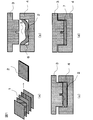
- FIG. 1 is a diagram showing an example of the manufacturing process of the present invention.
- a preform manufacturing process is performed.
- the preform 2 is produced by cutting the prepreg 1 into a predetermined shape using a cutter, a scissors, or an automatic cutter, and laminating them.
- the preform 2 is preferably covered with a bag film or the like and then the prepregs are brought into close contact with each other by evacuation.
- the preform 2 is produced by laminating a plurality of prepregs 1 here, in the present invention, it is not always necessary to form a laminate, and a single prepreg layer may be used as a preform.
- an arrangement / preheating step is performed as shown in FIG.
- the molds one mold 3 and the other mold 4
- the preform 2 is placed in the cavity 5 of the other mold 4.
- preheating of the preform is started, and the thermosetting resin starts a curing reaction.
- one mold 3 is closed to a predetermined position, and the preform is preheated for a predetermined time. It should be noted that there is no problem even if the preform 2 is arranged on one mold 3 with the other mold 4 being opposite in positional relationship.
- a pressing process is performed as shown in FIG.
- the preform 2 is pressed by one mold 3 and the other mold 4, the preform 2 is deformed into a cavity shape which is a product shape.
- the preform 2 is pressurized with almost no flow out of the mold and fills almost all of the cavity 5.
- a preform is produced by laminating cut prepregs. Only one prepreg layer may be used as a preform. Further, the preform may be configured not only by arranging the flat prepreg as it is, but also by forming a roll shape, folding it, or combining them as shown in FIG.
- the prepreg used in the present invention is composed of reinforcing fibers and a thermosetting resin.
- a continuous fiber As a form of the reinforcing fiber used for the prepreg, for example, a continuous fiber can be used.
- a prepreg preform using continuous fibers as reinforcing fibers can be exemplified as a structure having high strength because the strength of the fibers can be easily utilized when the molded product is exposed to a load.
- a prepreg using continuous fibers a unidirectional prepreg in which the continuous fibers are arranged in the same direction, a woven prepreg in which the continuous fibers are woven, or a braided braid of continuous fibers is impregnated with resin. It can be illustrated.
- a cut may be partially inserted into a prepreg using continuous fibers as reinforcing fibers (that is, a plurality of cuts may be made so as to cross the continuous fibers) and used as a cut insertion prepreg. From the viewpoint of mechanical properties, it is preferable to insert a cut into a unidirectional prepreg and use it as a cut insertion prepreg.
- the notched insertion prepreg can be used for a preform in combination with a normal prepreg in which a reinforcing fiber is a continuous fiber and no notching is required.
- the use of the slit insertion prepreg for the preform can be exemplified as one of the preferred embodiments of the present invention.
- this prepreg an opening and a shift are likely to occur at the cut insertion position, and the extensibility of the prepreg in the reinforcing fiber direction is improved.
- the flow at the time of compression molding opens the cut insertion part and the fiber bundles of the reinforcing fibers are separated from each other, so that flexibility is exhibited as a prepreg, and the fluidity is increased.
- the reinforcing fiber reaches the end of the molded product.
- the cut surface of the cut insertion portion penetrates in the thickness direction of the prepreg (that is, the cut enters the entire area in the thickness direction of the prepreg).
- the length of the cut reinforcing fiber included in the insertion prepreg is preferably 3 mm or more and 100 mm or less, more preferably 5 mm or more and 75 mm or less, and further preferably 10 mm. It is 50 mm or less.
- the molded product exhibits sufficient mechanical properties.
- the preform can obtain sufficient fluidity at the time of molding.
- the cutting length (cutting depth) of the cut insertion portion varies depending on the angle formed by the cutting direction and the principal axis direction of the prepreg reinforcing fiber, but is preferably 0 as the projected length of the prepreg reinforcing fiber in the direction perpendicular to the fiber. 0.05 mm or more and 25 mm or less, more preferably 0.1 mm or more and 10 mm or less, and further preferably 0.15 mm or more and 5 mm or less.
- the cutting length By setting the cutting length to be equal to or more than the lower limit value of the above preferable range, the opening amount of the cut insertion portion is increased, and the preform exhibits sufficient fluidity.
- the cutting length by setting the cutting length to be equal to or less than the upper limit value of the above preferable range, it is possible to suppress the opening of the cut insertion portion and obtain a molded product having excellent appearance quality and mechanical characteristics.
- the volume content of the reinforcing fiber preferable as the prepreg is preferably 40% or more and less than 80%, more preferably 45% or more and less than 75%, and further preferably 50% or more and less than 70%.
- the unidirectional prepreg and the cutting insertion prepreg are excellent in the filling efficiency of the reinforcing fiber, and are suitable for drawing out the reinforcing effect of the reinforcing fiber, and are effective in improving the rigidity of the molded product. is there.
- the amount of the reinforcing fiber contained in the prepreg is preferably 50 gsm or more and less than 1000 gsm as the basis weight (g / m 2 ) of the reinforcing fiber when the sheet-like product is used.
- a prepreg whose precursor is a small piece or a chopped fiber bundle in which a reinforcing fiber bundle is impregnated with a thermosetting resin, if the basis weight is too small, pores in which reinforcing fibers are not present in the surface of the prepreg may be generated.
- the basis weight By setting the basis weight to be equal to or higher than the lower limit value of the above preferable range, it becomes possible to eliminate pores that become weak portions in the fiber reinforced resin.
- the basis weight is less than the upper limit of the preferable range, heat can be uniformly transferred to the inside during preheating of the molding.
- the basis weight is more preferably 100 gsm or more and less than 600 gsm, and further preferably 150 gsm or more and less than 400 gsm, in order to achieve both the uniformity of the structure and the uniformity of heat transfer.
- the measurement of the basis weight of the reinforcing fiber is performed by cutting out a 10 cm square region from the reinforcing fiber sheet, measuring its mass, and dividing by the area. The measurement is performed 10 times for different parts of the reinforcing fiber sheet, and the average value is adopted as the basis weight of the reinforcing fiber.
- a prepreg including a portion in which the thermosetting resin is not impregnated in the reinforcing fiber can also be used.
- the non-impregnated part is a part where the thermosetting resin is not attached to the surface of the reinforcing fiber.
- the portion of the prepreg that is not impregnated with resin is impregnated with thermosetting resin that flows from other portions through compression molding such as press molding, and can exhibit desired characteristics as a healthy portion.
- the reinforcing fiber used for the prepreg for example, carbon fiber, glass fiber, aramid fiber, alumina fiber, silicon carbide fiber, boron fiber, metal fiber, natural fiber, and mineral fiber can be used. Species or two or more can be used in combination. Among these, PAN-based, pitch-based and rayon-based carbon fibers are preferably used from the viewpoint of high specific strength and specific rigidity and light weight reduction effect. Further, from the viewpoint of increasing the conductivity of the obtained molded product, a reinforcing fiber coated with a metal such as nickel, copper, or ytterbium can also be used.
- a metal such as nickel, copper, or ytterbium
- thermosetting resin examples include resins such as unsaturated polyester, vinyl ester, epoxy, phenol, urea melamine, maleimide and polyimide, copolymers, modified products, and at least of these.
- a resin obtained by blending two types is mentioned.
- an epoxy resin is preferably used from the viewpoint of mechanical properties of the obtained molded product.
- the uncured glass transition temperature of the thermosetting resin used is preferably 80 ° C. or less, more preferably 70 ° C. or less. Yes, more preferably 60 ° C or lower.
- the degree of cure of the thermosetting resin can be measured, for example, by comparing the calorific values before and after the reaction using a differential scanning calorimeter. That is, when the heat generation amount of a prepreg having a curing degree of a thermosetting resin of 0% is H0 (J) and the heat generation amount of the prepreg to be measured is H1 (J), the degree of cure ⁇ (%) is obtained by the following equation. Can do.
- ⁇ ⁇ (H0 ⁇ H1) / H0 ⁇ ⁇ 100 (Preform structure)
- a prepreg cut into a desired shape is used alone, a plurality of prepregs are laminated, or a plurality of laminates of the prepregs are combined to produce a preform suitable for the product shape, for molding.
- a plurality of divided preforms can be used as the preform, that is, a desired product shape can be composed of a plurality of preforms.
- Preforms such as prepreg laminates are preferably pre-shaped into a three-dimensional shape.
- a preform When such a preform is used, it becomes a shape close to the shape of the mold cavity, so that the flow during the press molding of the preform such as a prepreg laminate can be suppressed, and the disturbance of the reinforcing fibers contained in the preform can be suppressed.
- a molded product having excellent mechanical properties can be obtained.
- the shape of the preform is close to the shape of the molded product, it is easy to place the preform in the mold cavity.
- the volume of the preform is preferably close to the product shape.
- the volume of the preform is preferably 100% or more and 120% or less of the volume of the obtained molded product. By setting it to 100% or more, a sufficient molding pressure can be applied to the preform. On the other hand, by setting it as 120% or less, the outflow of the material out of a product shape can be suppressed, and a material yield improves.
- the thickness of the preform is preferably 80% or more and 200% or less of the product shape in any region.
- in-plane such as providing a region of 80% or more and less than 100 and a region of 100% or more and 200% or less. It is preferable to have a distribution.
- the region having a thickness of 100% or more and 200% or less can be provided while keeping the volume of the preform at 100% or more and 120% or less.
- the region having a thickness of 100% or more and 200% or less is in contact with both one mold and the other mold at the same time prior to the other region (thin region) in the arrangement / preheating process.
- the curing reaction of the resin is promoted more than the region. As a result, the fiber flow is suppressed by suppressing the material flow, and burrs can be reduced.
- the area of the planar state of the preform is greater than or equal to the projected area of the mold cavity.
- the “area in a planar state” refers to a projected area in the thickness direction of the preform when the preform is not arranged on a mold but is simply arranged on a plane. For example, when a preform as shown in FIG. 5 is used, the area projected in the vertical direction on the paper surface as shown in FIG. 5 becomes the “area in the plane state”.
- the projection direction of the projection area of the mold cavity is the mold opening direction.
- the entire outer periphery of the preform can be brought into contact with the mold prior to the center of the preform (region other than the specific portion) as the specific portion.
- This configuration is particularly effective when the mold has a standing wall on the outer periphery of the cavity.
- the preform may be configured not only by arranging the flat prepreg as it is, but also by forming a roll shape, folding it, or combining them as shown in FIG.
- a prepreg laminate and a rough-shaped preform element prepreg
- the rough-shaped preform element is, for example, a scroll structure in which a prepreg is wound up (FIG. 5 (a)), a folded structure in which the prepreg is folded (FIG. 5 (b)), or a part thereof is pulled out from the structure. The thing of the structure deformed linearly by this.
- the rough-shaped preform element the time required for stacking the prepregs can be omitted.
- the laminate of prepreg and the rough-shaped preform element are fixed.
- proper handling is provided in the process of preform transportation and the placement of the preform in the mold cavity, and the relative positional relationship between the prepreg and the rough-shaped preform element is determined between the processes. It will be maintained for a long time.
- the yield of molded products is improved.
- Examples of the fixing method include a method of fixing by pressing using a prepreg tack, and a method of fixing using vibration welding, ultrasonic welding, or the like.
- the degree of curing ⁇ e of the thermosetting resin in the specific part of the preform is higher than the degree of curing ⁇ i of the thermosetting resin in the region other than the specific part of the preform at the start of the pressing step. make it big. Therefore, it is preferable to use a prepreg having a higher degree of curing of the thermosetting resin than the region other than the specific portion of the preform for the specific portion of the preform.
- (c) the degree of curing ⁇ e (%) of the thermosetting resin in the specific part in the pressing step is larger than the degree of curing ⁇ i (%) of the thermosetting resin in the region other than the specific part of the preform. Therefore, it is possible to follow the complex shape with sufficient material flow except for the specific part while suppressing the fiber disturbance by suppressing the material flow in the specific part, and the molded product with excellent mechanical properties and product appearance can be obtained. Obtainable.
- the degree of cure ⁇ i (%) of the thermosetting resin in the region other than the specific part of the preform is preferably 0.5% or more and 30% or less at the start of the pressing process. If the degree of cure ⁇ i is too small, the preform is easily deformed during handling, and the placement accuracy on the mold may be reduced. By setting the curing degree ⁇ i to be equal to or higher than the lower limit value of the above preferable range, the accuracy of the placement of the preform is improved. On the other hand, if the degree of cure ⁇ i is too large, the thermosetting resin may gel before the preform flows due to the molding pressure of press molding, and sufficient fluidity may not be obtained. By setting the degree of curing ⁇ i to be equal to or less than the upper limit of the above preferable range, the preform can obtain sufficient fluidity at the time of molding.
- the decorative film preferably has a design and / or a geometric pattern on the film surface.
- a resin having a visible light transmittance of 80 to 100% is preferably used.
- the color tone film preferably contains an organic and / or inorganic pigment or colorant.
- a gloss film, a print film, an antistatic film, a light shielding film, a heat resistant film, and the like can be used as necessary.
- the specific portion of the preform is preferably a region where a large load or strain is generated when the product is used, from the viewpoint of improving the mechanical properties of the product by suppressing fiber disturbance.
- the specific part of the preform is preferably a region exposed to the outside when the product is used from the viewpoint of suppressing the fiber disturbance and improving the appearance of the product.
- the specific part of the preform is preferably the peripheral part of the preform from the viewpoint of suppressing material flow and suppressing burrs.
- the peripheral portion of the preform is substantially the peripheral portion of the product shape, but the entire peripheral portion needs to be a specific portion where the degree of cure of the thermosetting resin is larger than the others at the start of the pressing process. Rather, a plurality of specific parts can be set discontinuously as necessary.
- the peripheral portion may be the outer periphery of the shape, or may be a closed peripheral region inside the shape to be drilled and trimmed by post-processing.
- the area other than the specific part of the preform means a part where the preform needs to flow or stretch more than the specific part of the preform in order to form a desired product shape. Point to.
- the peripheral part of the preform is selected as the specific part in order to suppress burrs as the specific part of the preform
- the inner area surrounded by the peripheral part of the preform becomes an area other than the specific part, and the specific part
- the area other than the specific part of the preform is the peripheral part of the preform.
- the arrangement / preheating step is basically a step from when the preform is arranged in one mold and heating of the preform is started until the other mold comes into contact with the preform.
- the preform is placed in one mold cavity and preheated.
- the mold used in the present invention may be any mold that can cure the preform under high temperature and high pressure. At least one mold and the other mold (upper mold / lower mold or male mold / Female type). Each mold can have a split structure or a nested structure. A cavity including a product shape is provided between the two molds of at least one mold and the other mold. The mold is temperature-controlled by an electric heater or a heat medium, and the cavity is heated to the molding temperature.
- the airtightness means that the epoxy resin constituting the preform does not substantially leak from the mold even when a sufficient amount of preform to fill the mold is placed in the mold and pressed.
- Examples of the mold that keeps the inside airtight include a mold that employs a shear edge structure or a rubber seal structure at a portion where one mold contacts the other mold when the mold is tightened.
- a mold adopting any structure may be used as long as the inside of the mold is kept airtight.
- the degree of curing ⁇ e of the thermosetting resin in the specific part of the preform is higher than the degree of curing ⁇ i of the thermosetting resin in the region other than the specific part of the preform at the start of the pressing step.
- the mold used in the present invention is preferably provided with a convex portion at a position corresponding to the specific portion of the preform.
- the convex portion may have a standing wall shape.
- a convex part is a standing wall shape, it is preferable to provide in the position corresponding to the peripheral part of a product shape.
- the mold used in the present invention preferably has a position corresponding to a specific part of the preform at a higher temperature than other parts.
- a specific part of the mold has a nesting structure and the nesting is heated by an electric heater or a heat medium so that the temperature is higher than other parts
- the specific part of the preform is heated at a higher temperature than the other region.
- the degree of cure of the specific part is greater than in other areas.
- the temperature of the mold in the arrangement / preheating step is preferably 100 ° C. or higher and lower than 220 ° C., although it depends on the thermosetting resin used. If the preheating temperature of the mold is 100 ° C. or higher, the resin can sufficiently undergo a curing reaction, and a molded product can be obtained with high productivity. Moreover, if this temperature is less than 220 degreeC, generation
- the preform is placed in the cavity of the one mold by hand, a jig, or an automatic machine.
- the preform it is desirable to place the preform so that the specific part contacts the mold. For example, when using a preform whose planar area is equal to or larger than the projected area of the mold cavity, place the preform while folding it as necessary, bring specific parts into contact with the mold, and place other areas on the mold. It is preferable not to contact it. By doing so, the degree of cure of the specific portion becomes larger than in other regions, and the material flow is suppressed in the pressing process, and fiber disturbance can be reduced.
- thermosetting resin starts a curing reaction.
- the other mold is closed to a predetermined position, and the preform is preheated for a predetermined time.
- the specific part of the preform is preferably preheated for a longer time or at a higher temperature than the region other than the specific part of the preform by the method using the mold or the arrangement method described above.
- the predetermined position is preferably 0 mm or more and 100 mm or less, and more preferably 0 mm or more and 10 mm or less. By setting it to 0 mm or more, the contact of the mold with the preform can be minimized, and the displacement of the preform and the disturbance of the fibers can be suppressed. By setting it to 100 mm or less, cooling of the preform due to the atmosphere outside the mold can be suppressed, and the preform can be sufficiently preheated.
- the predetermined position is a value representing a difference between the relative position relationship between the one mold and the other mold when the final mold clamping is completed is 0 mm.
- the preheating time at the predetermined position is preferably 0 seconds or more and 30 minutes or less. Although depending on the arrangement time of the preform, when a resin having a quick reaction is used, the preheating process time may be set to 0 seconds.
- the viscosity of the resin immediately before the pressing process is 10 Pa ⁇ s or more and 1000 Pa ⁇ s or less by preheating. If the resin viscosity is too small, only the resin of the prepreg flows so as to exude from the prepreg, but by setting the viscosity to 10 Pa ⁇ s or more, the reinforcing fiber can also flow with the resin, and the mechanical properties and appearance of the molded product Will improve. On the other hand, if the resin viscosity is too large, the preform may not easily follow the product shape, or the entire reinforcing fiber may not be impregnated with the resin and the surface appearance of the molded product may be impaired. By setting the viscosity to 1000 Pa ⁇ s or less, the preform follows the product shape, and the entire reinforcing fiber is impregnated with the resin.
- the pressing process is a process of deforming the preform with a mold, and is a process from the completion of the preheating / placement process until the preform follows the product shape.
- the clamping speed of the press is preferably 0.2 mm / s or more and 50 mm / s or less, more preferably 0.5 mm / s or more and 25 mm / s or less, and 1.2 mm / s or more and 12 mm / s. More preferably, it is as follows.
- the molding pressure can be obtained by dividing the press load by the projected area of the cavity in the mold clamping direction. If the molding pressure is too small, the preform does not sufficiently follow the product shape. If the molding pressure is too large, the molding apparatus becomes large and the productivity is lowered. Therefore, the gauge pressure is preferably 0.1 MPa or more and 30 MPa.
- the curing process refers to a process from when the preform follows the product shape until the curing of the thermosetting resin is completed. In the curing step, the preform does not substantially flow, and the thermosetting resin is cured in a state in which fiber disturbance and burrs at the specific portion are suppressed, and a molded product is obtained.
- the mold is opened and the molded product is removed.
- the demolded molded product is subjected to post-processing such as trimming and drilling as necessary to obtain a final product shape.
- the degree of cure ⁇ e of the thermosetting resin in the specific part of the preform at the start of the pressing step is the degree of cure of the thermosetting resin in the region other than the specific part of the preform.
- a prepreg having a higher degree of curing of a thermosetting resin than a region other than the specific part is used for the specific part, or (ii) the specific part is Preheating at a temperature higher than the area other than the specific part, (iii) Preheating the specific part for a longer time than the area other than the specific part, or (iv) The specific part being an area other than the specific part
- these may be used alone or in combination of two or more at the same time.
- Preform dimensions The thickness, width and length of the prepreg constituting the preform were measured in units of 1 mm using a caliper.
- the filling of the molded product was evaluated according to the following criteria by polishing and observing the cross section of the end of the molded product. A and B were accepted. A: Chipping due to poor filling is not observed in the molded product, and both fiber reinforcement and thermosetting resin are present at the end of the molded product. B: Chipping due to poor filling is not observed in the molded product, but only the thermosetting resin is present at the end of the molded product. C: Chipping due to poor filling is observed in the molded product.
- Molded product burrs The burrs of the molded products were evaluated according to the following criteria. A was accepted. A: Chipping due to poor filling is not observed in the molded product, and the weight W2 (g) of burrs generated outside the cavity shape at a specific portion of the preform is less than 1% of the product weight W3 (g). C: Chipping due to poor filling is observed in the molded product, or the weight W2 (g) of burrs generated outside the cavity shape at a specific portion of the preform is 1% or more of the product weight W3 (g).
- the weight W2 (g) of the burr generated in the specific part was obtained as a difference between the weight W0 (g) of the molded product at the time of demolding and the weight W1 (g) of the molded product after trimming the peripheral part as the specific part. .
- the product weight W3 (g) was the weight of the molded product after trimming all necessary parts other than the specific part.
- the prepreg used in the examples of the present invention is as follows.
- prepreg As the prepreg, unidirectional prepreg P3432S-20 (manufactured by Toray Industries, Inc.) was used. The characteristics of this prepreg are as follows. Hereinafter, this is referred to as a prepreg (A). Carbon fiber density: 1.80 g / cm 3 -Carbon fiber tensile strength: 4.9 GPa Carbon fiber tensile elastic modulus: 230 GPa ⁇ Threading: 200 -Resin content: 33% ⁇ Thickness: 0.19mm [Insertion prepreg] A notch insertion prepreg was produced by inserting notches into the prepreg (A) using an automatic cutter.
- the cutting length (cutting depth) of the cutting insertion location is 1 mm (projection length of the reinforcing fiber in the direction perpendicular to the fiber is 0.24 mm), and the angle formed by the cutting direction and the principal axis direction of the reinforcing fiber of the prepreg is 14 °
- the average length of the reinforcing fibers cut by the cutting was 25 mm.
- the notch was penetrated in the thickness direction of the prepreg.
- the characteristics other than the cutting are the same as those of the unidirectional prepreg (A) described above. Hereinafter, this is referred to as a prepreg (B).
- Example 1 The angle between the prepreg (A) in the length direction (the direction in which the cavity 5 becomes the length direction 11 when arranged in the cavity 5 shown in FIG. 4) and the principal axis direction of the reinforcing fiber is 0, ⁇ 45, 90 degrees.
- a laminated body of prepreg (1) ie, a preform having a length of 102 mm and a width of 102 mm, laminated so that the laminated structure is [45/0 / ⁇ 45 / 90] 2 s. Got. Two of these were produced.
- Each number in [45/0 / ⁇ 45 / 90] represents the angle (°) between the longitudinal direction and the principal axis direction of the reinforcing fiber, where the longitudinal direction is the 0 ° direction.
- “2s” refers to a mode in which a laminate in which the combination in [] is repeated twice and a laminate in the reverse order of the laminate are prepared and laminated so as to be symmetrical. Show. For one of the obtained prepreg laminates (1), the dimensions and the degree of cure were measured by the methods described above.
- the specific portion of the preform that increases the degree of curing of the thermosetting resin is defined as the entire peripheral portion that is the outer periphery of the preform, and the laminate is brought into contact with the standing wall portion 6 of the mold shown in FIG. And a preheating step was performed, and the preform was taken out of the mold.
- the degree of cure of the preform peripheral portion as the specific portion of the preform and the central portion of the preform as the region other than the specific portion of the preform immediately before the pressing step was measured by the method described above.
- the placement / preheating process is performed in the same manner using another laminate of prepregs, and then the preform is heated in the same mold for 10 minutes while being pressed at 5 MPa. The process was carried out to obtain a molded product.
- Table 1 shows the evaluation results of the degree of cure, the filling property of the molded product, the surface appearance of the molded product, and the burr of the molded product.
- Example 2 The prepreg (B) was cut into a size of 100 mm in length and 80 mm in width so that the angle formed between the length direction and the principal axis direction of the reinforcing fiber was 0, ⁇ 45, and 90 degrees, and the laminated configuration was [45 / 0 / -45 / 90] are stacked so that the 2s, give laminate prepreg (2-1). Two of these were produced. Further, the prepreg (A) is cut into a size of 100 mm length ⁇ 10 mm width, and laminated so that the laminated structure becomes [45/0 / ⁇ 45 / 90] 2 s, and the prepreg laminated body (2-2) Got. Four of these were produced. With respect to each of the obtained prepreg laminates (2-1) and (2-2), the dimensions and the degree of cure were measured by the methods described above.
- the specific part of the preform that increases the degree of curing of the thermosetting resin is determined as the inside of the preform that is the main part of the product, and the laminate (2-1) is placed in the center of the mold shown in FIG. .
- a total of two laminates (2-2) were arranged on both sides of the laminate (2-1), and a preheating step was performed.
- Example 1 shows the results of the evaluated degree of cure, filling property of the molded product, and surface appearance of the molded product.
- Example 3 The prepreg (B) was cut into dimensions of 95 mm length ⁇ 110 mm width so that the angle formed by the length direction and the principal axis direction of the reinforcing fiber was 0, ⁇ 45, 90 degrees, and the laminated structure was [45 / 0 / -45 / 90] was laminated so as to be 2 s, and a prepreg laminate (3), that is, a preform was obtained. Two of these were produced. For one of the obtained prepreg laminates (3), the dimensions and the degree of cure were measured by the methods described above.
- the specific part of the preform that increases the degree of curing of the thermosetting resin is defined as two peripheral sides on the short side (95 mm side) on the outer periphery of the preform, as shown in FIG.
- the laminate was placed while curving so that the two sides on the short side were in contact with the standing wall of the mold, and a preheating step was further performed.
- the degree of cure immediately before the pressing step was measured at two sides of the outer periphery of the preform as the specific part of the preform and the central part of the preform as an area other than the specific part of the preform.
- Example 1 shows the evaluation results of the degree of cure, the filling property of the molded product, the surface appearance of the molded product, and the burr of the molded product.
- Example 4 The prepreg (B) was cut into a size of 100 mm in length and 80 mm in width so that the angle formed between the length direction and the principal axis direction of the reinforcing fiber was 0, ⁇ 45, and 90 degrees, and the laminated configuration was [45 / 0 / ⁇ 45 / 90] was laminated to 2 s to obtain a prepreg laminate (4-1). Two of these were produced. Further, the prepreg (C) was cut into a dimension of length 100 mm ⁇ width 10 mm, and laminated so that the laminated structure was [45/0 / ⁇ 45 / 90] 2 s, and the prepreg laminate (4-2) Got. Four of these were produced. With respect to each of the obtained prepreg laminates (4-1) and (4-2), the dimensions and the degree of cure were measured by the methods described above.
- the specific part of the preform that increases the degree of cure of the thermosetting resin is determined as the two peripheral sides on the long side of the laminate (4-2) on the outer periphery of the preform (that is, the laminate (4- 1) In a 100 mm square preform formed by arranging (4-2) side by side, the laminate (4-2) side corresponding to the outer periphery), and the laminate (4-1) at the center of the mold
- the laminate (4-2) was placed on both sides of the laminate (4-1) at the same time, and a preheating step was performed.
- the degree of cure immediately before the pressing step was measured at two sides of the outer periphery of the preform as the specific part of the preform and the central part of the preform as an area other than the specific part of the preform.
- Example 1 shows the evaluation results of the degree of cure, the filling property of the molded product, the surface appearance of the molded product, and the burr of the molded product.
- Example 5 The prepreg (B) was cut into a size of 100 mm in length and 80 mm in width so that the angle formed between the length direction and the principal axis direction of the reinforcing fiber was 0, ⁇ 45, and 90 degrees, and the laminated configuration was [45 / 0 / ⁇ 45 / 90] was laminated to 2 s to obtain a prepreg laminate (5-1). Two of these were produced. Further, the prepreg (C) was cut into dimensions of 100 mm length ⁇ 10 mm width, and laminated so that the laminated structure was [45/0 / ⁇ 45 / 90] 2 s, and the prepreg laminate (5-2) Got. Four of these were produced. For each of the obtained prepreg laminates (5-1) and (5-2), the dimensions and the degree of cure were measured by the methods described above.
- the specific part of the preform that increases the degree of cure of the thermosetting resin is determined as the two peripheral sides on the long side of the laminate (5-2) on the outer periphery of the preform (that is, the laminate (5- 1) In a 100 mm square preform formed by arranging (5-2) side by side, the laminate (5-1) side corresponding to the outer periphery thereof, and the laminate (5-1) at the center of the mold
- the laminate (5-2) is placed on both sides of the laminate (5-1) at the same time and immediately clamped, the time corresponding to the time until the mold contacts the preform has elapsed.
- the laminates (5-1) and (5-2) were taken out from the mold.
- the degree of cure immediately before the pressing step was measured at two sides of the outer periphery of the preform as the specific part of the preform and the central part of the preform as an area other than the specific part of the preform.
- Example 1 shows the evaluation results of the degree of cure, the filling property of the molded product, the surface appearance of the molded product, and the burr of the molded product.
- Example 6 The prepreg (B) was cut into dimensions of 102 mm length ⁇ 102 mm width so that the angle formed between the length direction and the principal axis direction of the reinforcing fiber was 0, ⁇ 45, 90 degrees, and the laminated structure was [45 / 0 / ⁇ 45 / 90] was laminated so as to be 2 s to obtain a prepreg laminate (6), that is, a preform. Two of these were produced. About one piece of the laminated body (6) of the obtained prepreg, the dimension and the hardening degree were measured by the above-mentioned method.
- the specific portion of the preform that increases the degree of cure of the thermosetting resin is defined as the entire peripheral portion that is the outer periphery of the preform, and the temperature of an electric heater (not shown) in the vicinity of the standing wall portion 6 in the mold shown in FIG.
- the average surface temperature of the standing wall 6 was made 10 ° C. higher than the average temperature in other regions.
- the laminate was placed while bringing the peripheral edge into contact with the standing wall 6 of the mold shown in FIG. 4, and a preheating step was further performed to take out the preform from the mold.
- a preheating step was further performed to take out the preform from the mold.
- the degree of cure of the preform peripheral portion as the specific portion of the preform and the central portion of the preform as the region other than the specific portion of the preform immediately before the pressing step was measured by the method described above.
- the placement / preheating process is performed in the same manner using another laminate of prepregs, and then the preform is heated in the same mold for 10 minutes while being pressed at 5 MPa. The process was carried out to obtain a molded product.
- Table 1 shows the evaluation results of the degree of cure, the filling property of the molded product, the surface appearance of the molded product, and the burr of the molded product.
- Example 1 shows the evaluation results of the degree of cure, the filling property of the molded product, the surface appearance of the molded product, and the burr of the molded product.
- Example 1 shows the evaluation results of the degree of cure, the filling property of the molded product, the surface appearance of the molded product, and the burr of the molded product.
- the degree of curing ⁇ e of the thermosetting resin in the specific part of the preform is made larger than the degree of curing ⁇ i of the thermosetting resin in the region other than the specific part of the preform.
- the preform has a good flow in the region other than the specific portion while suppressing the flow of the preform in the specific portion.
- a molded product having no chipping to the end was obtained, and a molded product having excellent surface appearance and good mechanical properties with almost no voids or resin richness was obtained.
- Comparative Example 1 the specific part was not provided, and the entire in-plane of the laminate was molded with a uniform degree of curing, so that large burrs were seen on the outer periphery of the molded product, and the flow was hindered and a large resin rich Resulting in inferior surface appearance. Furthermore, in Comparative Example 2, although no resin rich was observed, fiber disturbance occurred on the outer periphery of the molded product.
- the present invention is particularly suitable when press forming a three-dimensional shape having a thickness change such as a thick portion or a protrusion in a wide range of fields such as sports and leisure applications such as fishing rods and golf shafts, and industrial applications such as automobiles and aircraft. Is preferred.
- Prepreg 2 Preform 3
- One mold (upper mold) 4
- the other mold (lower mold) 5
- Cavity 6 Convex (standing wall) 7
- Molded product 8 Specific part 9
- Area other than specific part 10 Closed peripheral area 11 inside the shape to be drilled and trimmed by post-processing 11 Length direction
Landscapes
- Engineering & Computer Science (AREA)
- Chemical & Material Sciences (AREA)
- Mechanical Engineering (AREA)
- Composite Materials (AREA)
- Materials Engineering (AREA)
- Textile Engineering (AREA)
- Health & Medical Sciences (AREA)
- Chemical Kinetics & Catalysis (AREA)
- Polymers & Plastics (AREA)
- Manufacturing & Machinery (AREA)
- Organic Chemistry (AREA)
- Medicinal Chemistry (AREA)
- Physics & Mathematics (AREA)
- Oral & Maxillofacial Surgery (AREA)
- Thermal Sciences (AREA)
- Civil Engineering (AREA)
- Structural Engineering (AREA)
- Architecture (AREA)
- Casting Or Compression Moulding Of Plastics Or The Like (AREA)
- Reinforced Plastic Materials (AREA)
- Moulding By Coating Moulds (AREA)
Abstract
Priority Applications (9)
| Application Number | Priority Date | Filing Date | Title |
|---|---|---|---|
| RU2020130913A RU2020130913A (ru) | 2018-03-29 | 2019-03-11 | Способ получения фиброармированной смолы |
| US16/979,238 US20200398461A1 (en) | 2018-03-29 | 2019-03-11 | Method of producing fiber-reinforced resin |
| BR112020014078-3A BR112020014078A2 (pt) | 2018-03-29 | 2019-03-11 | Método de produção de resina reforçada com fibra |
| CN201980020838.8A CN111886119A (zh) | 2018-03-29 | 2019-03-11 | 纤维增强树脂的制造方法 |
| AU2019244244A AU2019244244A1 (en) | 2018-03-29 | 2019-03-11 | Method for producing fiber-reinforced resin |
| JP2019514320A JPWO2019188195A1 (ja) | 2018-03-29 | 2019-03-11 | 繊維強化樹脂の製造方法 |
| CA3088144A CA3088144A1 (fr) | 2018-03-29 | 2019-03-11 | Procede de production de resine renforcee de fibres |
| EP19774352.9A EP3778172A4 (fr) | 2018-03-29 | 2019-03-11 | Procédé de production de résine renforcée de fibres |
| KR1020207013487A KR20200133203A (ko) | 2018-03-29 | 2019-03-11 | 섬유 강화 수지의 제조 방법 |
Applications Claiming Priority (2)
| Application Number | Priority Date | Filing Date | Title |
|---|---|---|---|
| JP2018064223 | 2018-03-29 | ||
| JP2018-064223 | 2018-03-29 |
Publications (1)
| Publication Number | Publication Date |
|---|---|
| WO2019188195A1 true WO2019188195A1 (fr) | 2019-10-03 |
Family
ID=68058876
Family Applications (1)
| Application Number | Title | Priority Date | Filing Date |
|---|---|---|---|
| PCT/JP2019/009714 WO2019188195A1 (fr) | 2018-03-29 | 2019-03-11 | Procédé de production de résine renforcée de fibres |
Country Status (10)
| Country | Link |
|---|---|
| US (1) | US20200398461A1 (fr) |
| EP (1) | EP3778172A4 (fr) |
| JP (1) | JPWO2019188195A1 (fr) |
| KR (1) | KR20200133203A (fr) |
| CN (1) | CN111886119A (fr) |
| AU (1) | AU2019244244A1 (fr) |
| BR (1) | BR112020014078A2 (fr) |
| CA (1) | CA3088144A1 (fr) |
| RU (1) | RU2020130913A (fr) |
| WO (1) | WO2019188195A1 (fr) |
Cited By (1)
| Publication number | Priority date | Publication date | Assignee | Title |
|---|---|---|---|---|
| EP3736203A4 (fr) * | 2018-10-03 | 2021-06-02 | Kawasaki Jukogyo Kabushiki Kaisha | Composant composite pour aéronef et procédé de fabrication de celui-ci |
Families Citing this family (3)
| Publication number | Priority date | Publication date | Assignee | Title |
|---|---|---|---|---|
| KR102529929B1 (ko) | 2021-10-26 | 2023-05-08 | 현대제철 주식회사 | 복합 소재 제조 시스템 및 방법 |
| FR3141378A1 (fr) * | 2022-10-26 | 2024-05-03 | Safran | Procede de fabrication d’une piece en materiau composite a matrice thermodurcissable renforcee par des fibres longues discontinues |
| CN116214777B (zh) * | 2023-05-10 | 2023-07-18 | 宁海县第一注塑模具有限公司 | 一种成型碳纤维的注塑模具 |
Citations (8)
| Publication number | Priority date | Publication date | Assignee | Title |
|---|---|---|---|---|
| JPH10138269A (ja) * | 1996-11-12 | 1998-05-26 | Hitachi Chem Co Ltd | 積層板の製造方法 |
| JP2005335200A (ja) * | 2004-05-26 | 2005-12-08 | Matsushita Electric Works Ltd | 被覆成形体の製造方法及び製造装置 |
| JP2008068532A (ja) | 2006-09-14 | 2008-03-27 | Honda Motor Co Ltd | 繊維強化プラスチック製プリフォームの成形方法 |
| JP2008073875A (ja) * | 2006-09-19 | 2008-04-03 | Toray Ind Inc | Frp成形体の製造方法およびその成形体。 |
| WO2008093757A1 (fr) * | 2007-01-31 | 2008-08-07 | Kyocera Corporation | Processus de fabrication de feuille préimprégnée, son appareil et feuille préimprégnée |
| JP2014108612A (ja) * | 2012-12-04 | 2014-06-12 | Ehime Univ | 炭素繊維強化プラスチックの成形時の解析方法、及び解析装置 |
| JP2015143343A (ja) | 2013-12-25 | 2015-08-06 | 三菱レイヨン株式会社 | プリプレグ、及び成形品の製造方法 |
| US20170073460A1 (en) | 2014-05-28 | 2017-03-16 | Ajinomoto Co., Inc. | Polyether ketone compound |
Family Cites Families (8)
| Publication number | Priority date | Publication date | Assignee | Title |
|---|---|---|---|---|
| CN1944527A (zh) * | 2002-11-28 | 2007-04-11 | 三菱丽阳株式会社 | 预浸料用环氧树脂、预浸料、纤维增强复合材料及其制造方法 |
| WO2007013204A1 (fr) * | 2005-07-29 | 2007-02-01 | Toray Industries, Inc. | Tissu renforcé et son procédé de production |
| US20100181017A1 (en) * | 2006-09-29 | 2010-07-22 | Toray Industries, Inc. | Forming-molding tool and process for producing preforms and fiber reinforced plastics with the tool |
| WO2012066805A1 (fr) * | 2010-11-19 | 2012-05-24 | 三菱電機株式会社 | Procédé de production de plastique moulé renforcé de fibres, préforme, procédé de production de celle-ci, et film adhésif |
| JP6020826B2 (ja) * | 2013-07-12 | 2016-11-02 | パナソニックIpマネジメント株式会社 | 繊維強化複合材の成形方法および繊維強化複合材の成形装置 |
| JP6561629B2 (ja) * | 2015-07-06 | 2019-08-21 | 東レ株式会社 | 繊維強化複合材料の製造方法 |
| US10913236B2 (en) * | 2015-10-27 | 2021-02-09 | Toray Industries, Inc. | Incised prepreg, cross-ply laminate, and production method for incised prepreg |
| JP6688964B2 (ja) * | 2016-03-03 | 2020-04-28 | パナソニックIpマネジメント株式会社 | 熱プレス成形方法および熱プレス成形装置 |
-
2019
- 2019-03-11 RU RU2020130913A patent/RU2020130913A/ru unknown
- 2019-03-11 AU AU2019244244A patent/AU2019244244A1/en not_active Abandoned
- 2019-03-11 CA CA3088144A patent/CA3088144A1/fr active Pending
- 2019-03-11 CN CN201980020838.8A patent/CN111886119A/zh active Pending
- 2019-03-11 WO PCT/JP2019/009714 patent/WO2019188195A1/fr active Application Filing
- 2019-03-11 EP EP19774352.9A patent/EP3778172A4/fr not_active Withdrawn
- 2019-03-11 BR BR112020014078-3A patent/BR112020014078A2/pt not_active Application Discontinuation
- 2019-03-11 KR KR1020207013487A patent/KR20200133203A/ko not_active Application Discontinuation
- 2019-03-11 JP JP2019514320A patent/JPWO2019188195A1/ja not_active Withdrawn
- 2019-03-11 US US16/979,238 patent/US20200398461A1/en not_active Abandoned
Patent Citations (8)
| Publication number | Priority date | Publication date | Assignee | Title |
|---|---|---|---|---|
| JPH10138269A (ja) * | 1996-11-12 | 1998-05-26 | Hitachi Chem Co Ltd | 積層板の製造方法 |
| JP2005335200A (ja) * | 2004-05-26 | 2005-12-08 | Matsushita Electric Works Ltd | 被覆成形体の製造方法及び製造装置 |
| JP2008068532A (ja) | 2006-09-14 | 2008-03-27 | Honda Motor Co Ltd | 繊維強化プラスチック製プリフォームの成形方法 |
| JP2008073875A (ja) * | 2006-09-19 | 2008-04-03 | Toray Ind Inc | Frp成形体の製造方法およびその成形体。 |
| WO2008093757A1 (fr) * | 2007-01-31 | 2008-08-07 | Kyocera Corporation | Processus de fabrication de feuille préimprégnée, son appareil et feuille préimprégnée |
| JP2014108612A (ja) * | 2012-12-04 | 2014-06-12 | Ehime Univ | 炭素繊維強化プラスチックの成形時の解析方法、及び解析装置 |
| JP2015143343A (ja) | 2013-12-25 | 2015-08-06 | 三菱レイヨン株式会社 | プリプレグ、及び成形品の製造方法 |
| US20170073460A1 (en) | 2014-05-28 | 2017-03-16 | Ajinomoto Co., Inc. | Polyether ketone compound |
Non-Patent Citations (1)
| Title |
|---|
| See also references of EP3778172A4 |
Cited By (1)
| Publication number | Priority date | Publication date | Assignee | Title |
|---|---|---|---|---|
| EP3736203A4 (fr) * | 2018-10-03 | 2021-06-02 | Kawasaki Jukogyo Kabushiki Kaisha | Composant composite pour aéronef et procédé de fabrication de celui-ci |
Also Published As
| Publication number | Publication date |
|---|---|
| BR112020014078A2 (pt) | 2020-12-15 |
| CN111886119A (zh) | 2020-11-03 |
| KR20200133203A (ko) | 2020-11-26 |
| JPWO2019188195A1 (ja) | 2021-02-12 |
| US20200398461A1 (en) | 2020-12-24 |
| EP3778172A4 (fr) | 2021-12-22 |
| AU2019244244A1 (en) | 2020-07-30 |
| RU2020130913A (ru) | 2022-05-04 |
| CA3088144A1 (fr) | 2019-10-03 |
| EP3778172A1 (fr) | 2021-02-17 |
Similar Documents
| Publication | Publication Date | Title |
|---|---|---|
| WO2019188195A1 (fr) | Procédé de production de résine renforcée de fibres | |
| KR101926945B1 (ko) | 섬유 강화 복합 재료 성형품 및 그 제조 방법 | |
| EP2091720B1 (fr) | Appareil et procédés permettant de former des pièces composites renforcées de chapeau au moyen de plaques d'outillage à dilatation thermique | |
| JP5167953B2 (ja) | 積層基材、繊維強化プラスチック、およびそれらの製造方法 | |
| JP5292972B2 (ja) | 繊維強化プラスチックの製造方法 | |
| JP6883527B2 (ja) | 繊維強化樹脂成形体の製造方法 | |
| JP6988812B2 (ja) | プリプレグ積層体及びプリプレグ積層体を用いた繊維強化プラスチックの製造方法 | |
| WO2019244994A1 (fr) | Feuille préimprégnée et son procédé de fabrication, article moulé en matériau composite renforcé de fibres et son procédé de fabrication, et procédé de fabrication d'une préforme | |
| JP2008246981A (ja) | 繊維強化複合材料の製造方法 | |
| JP2007118598A (ja) | プリフォームの製造方法および製造装置 | |
| CN108016054A (zh) | 碳纤维复合材料成型膜盘制造工艺 | |
| JP2021030466A (ja) | 繊維強化樹脂成形品の製造方法 | |
| JP6858541B2 (ja) | 複合材料成形体の製造方法 | |
| JP5221105B2 (ja) | 繊維強化樹脂製賦形品およびその製造方法 | |
| JP2021123041A (ja) | プリフォーム | |
| JP2023097542A (ja) | 複数のプリフォーム要素で構成される、3次元形状のプリフォームの製造方法 | |
| US20230015015A1 (en) | Method for manufacturing thermoplastic fiber-reinforced resin molded article | |
| JP6777152B2 (ja) | 繊維強化複合材料成形品の製造方法 | |
| WO2021200047A1 (fr) | Méthode de production d'un produit intermédiaire d'un composant d'avion, et composant d'avion | |
| WO2021192464A1 (fr) | Préforme et son procédé de production | |
| JP7230499B2 (ja) | 積層体 | |
| JP2023097543A (ja) | オーバーラップ部を有するプリフォームおよび成型体 | |
| US20090181208A1 (en) | Lightweight Quick-Heating Fiberglass Mold with Integrated Cooling Channels and Method of Producing | |
| CN114379110A (zh) | 一种超厚度变曲率复材制件的分模铺贴自适应软模成型方法 | |
| CN117429598A (zh) | 一种异形加筋变刚度复合材料结构及其成型方法 |
Legal Events
| Date | Code | Title | Description |
|---|---|---|---|
| ENP | Entry into the national phase |
Ref document number: 2019514320 Country of ref document: JP Kind code of ref document: A |
|
| 121 | Ep: the epo has been informed by wipo that ep was designated in this application |
Ref document number: 19774352 Country of ref document: EP Kind code of ref document: A1 |
|
| ENP | Entry into the national phase |
Ref document number: 3088144 Country of ref document: CA |
|
| ENP | Entry into the national phase |
Ref document number: 2019244244 Country of ref document: AU Date of ref document: 20190311 Kind code of ref document: A |
|
| NENP | Non-entry into the national phase |
Ref country code: DE |
|
| REG | Reference to national code |
Ref country code: BR Ref legal event code: B01A Ref document number: 112020014078 Country of ref document: BR |
|
| WWE | Wipo information: entry into national phase |
Ref document number: 2019774352 Country of ref document: EP |
|
| ENP | Entry into the national phase |
Ref document number: 2019774352 Country of ref document: EP Effective date: 20201029 |
|
| ENP | Entry into the national phase |
Ref document number: 112020014078 Country of ref document: BR Kind code of ref document: A2 Effective date: 20200709 |