WO2019188163A1 - ワイヤハーネス - Google Patents
ワイヤハーネス Download PDFInfo
- Publication number
- WO2019188163A1 WO2019188163A1 PCT/JP2019/009570 JP2019009570W WO2019188163A1 WO 2019188163 A1 WO2019188163 A1 WO 2019188163A1 JP 2019009570 W JP2019009570 W JP 2019009570W WO 2019188163 A1 WO2019188163 A1 WO 2019188163A1
- Authority
- WO
- WIPO (PCT)
- Prior art keywords
- connector
- wire harness
- shield
- terminal
- shield members
- Prior art date
- Legal status (The legal status is an assumption and is not a legal conclusion. Google has not performed a legal analysis and makes no representation as to the accuracy of the status listed.)
- Ceased
Links
Images

Classifications
-
- H—ELECTRICITY
- H01—ELECTRIC ELEMENTS
- H01B—CABLES; CONDUCTORS; INSULATORS; SELECTION OF MATERIALS FOR THEIR CONDUCTIVE, INSULATING OR DIELECTRIC PROPERTIES
- H01B7/00—Insulated conductors or cables characterised by their form
- H01B7/0045—Cable-harnesses
-
- H—ELECTRICITY
- H01—ELECTRIC ELEMENTS
- H01R—ELECTRICALLY-CONDUCTIVE CONNECTIONS; STRUCTURAL ASSOCIATIONS OF A PLURALITY OF MUTUALLY-INSULATED ELECTRICAL CONNECTING ELEMENTS; COUPLING DEVICES; CURRENT COLLECTORS
- H01R13/00—Details of coupling devices of the kinds covered by groups H01R12/70 or H01R24/00 - H01R33/00
- H01R13/648—Protective earth or shield arrangements on coupling devices, e.g. anti-static shielding
- H01R13/658—High frequency shielding arrangements, e.g. against EMI [Electro-Magnetic Interference] or EMP [Electro-Magnetic Pulse]
- H01R13/6591—Specific features or arrangements of connection of shield to conductive members
- H01R13/65912—Specific features or arrangements of connection of shield to conductive members for shielded multiconductor cable
- H01R13/65918—Specific features or arrangements of connection of shield to conductive members for shielded multiconductor cable wherein each conductor is individually surrounded by shield
-
- H—ELECTRICITY
- H01—ELECTRIC ELEMENTS
- H01R—ELECTRICALLY-CONDUCTIVE CONNECTIONS; STRUCTURAL ASSOCIATIONS OF A PLURALITY OF MUTUALLY-INSULATED ELECTRICAL CONNECTING ELEMENTS; COUPLING DEVICES; CURRENT COLLECTORS
- H01R13/00—Details of coupling devices of the kinds covered by groups H01R12/70 or H01R24/00 - H01R33/00
- H01R13/648—Protective earth or shield arrangements on coupling devices, e.g. anti-static shielding
- H01R13/658—High frequency shielding arrangements, e.g. against EMI [Electro-Magnetic Interference] or EMP [Electro-Magnetic Pulse]
- H01R13/6591—Specific features or arrangements of connection of shield to conductive members
- H01R13/6596—Specific features or arrangements of connection of shield to conductive members the conductive member being a metal grounding panel
-
- H—ELECTRICITY
- H01—ELECTRIC ELEMENTS
- H01R—ELECTRICALLY-CONDUCTIVE CONNECTIONS; STRUCTURAL ASSOCIATIONS OF A PLURALITY OF MUTUALLY-INSULATED ELECTRICAL CONNECTING ELEMENTS; COUPLING DEVICES; CURRENT COLLECTORS
- H01R4/00—Electrically-conductive connections between two or more conductive members in direct contact, i.e. touching one another; Means for effecting or maintaining such contact; Electrically-conductive connections having two or more spaced connecting locations for conductors and using contact members penetrating insulation
- H01R4/10—Electrically-conductive connections between two or more conductive members in direct contact, i.e. touching one another; Means for effecting or maintaining such contact; Electrically-conductive connections having two or more spaced connecting locations for conductors and using contact members penetrating insulation effected solely by twisting, wrapping, bending, crimping, or other permanent deformation
- H01R4/18—Electrically-conductive connections between two or more conductive members in direct contact, i.e. touching one another; Means for effecting or maintaining such contact; Electrically-conductive connections having two or more spaced connecting locations for conductors and using contact members penetrating insulation effected solely by twisting, wrapping, bending, crimping, or other permanent deformation by crimping
-
- H—ELECTRICITY
- H01—ELECTRIC ELEMENTS
- H01R—ELECTRICALLY-CONDUCTIVE CONNECTIONS; STRUCTURAL ASSOCIATIONS OF A PLURALITY OF MUTUALLY-INSULATED ELECTRICAL CONNECTING ELEMENTS; COUPLING DEVICES; CURRENT COLLECTORS
- H01R4/00—Electrically-conductive connections between two or more conductive members in direct contact, i.e. touching one another; Means for effecting or maintaining such contact; Electrically-conductive connections having two or more spaced connecting locations for conductors and using contact members penetrating insulation
- H01R4/58—Electrically-conductive connections between two or more conductive members in direct contact, i.e. touching one another; Means for effecting or maintaining such contact; Electrically-conductive connections having two or more spaced connecting locations for conductors and using contact members penetrating insulation characterised by the form or material of the contacting members
- H01R4/64—Connections between or with conductive parts having primarily a non-electric function, e.g. frame, casing, rail
-
- H—ELECTRICITY
- H05—ELECTRIC TECHNIQUES NOT OTHERWISE PROVIDED FOR
- H05K—PRINTED CIRCUITS; CASINGS OR CONSTRUCTIONAL DETAILS OF ELECTRIC APPARATUS; MANUFACTURE OF ASSEMBLAGES OF ELECTRICAL COMPONENTS
- H05K9/00—Screening of apparatus or components against electric or magnetic fields
- H05K9/0073—Shielding materials
- H05K9/0081—Electromagnetic shielding materials, e.g. EMI, RFI shielding
- H05K9/009—Electromagnetic shielding materials, e.g. EMI, RFI shielding comprising electro-conductive fibres, e.g. metal fibres, carbon fibres, metallised textile fibres, electro-conductive mesh, woven, non-woven mat, fleece, cross-linked
-
- B—PERFORMING OPERATIONS; TRANSPORTING
- B60—VEHICLES IN GENERAL
- B60R—VEHICLES, VEHICLE FITTINGS, OR VEHICLE PARTS, NOT OTHERWISE PROVIDED FOR
- B60R16/00—Electric or fluid circuits specially adapted for vehicles and not otherwise provided for; Arrangement of elements of electric or fluid circuits specially adapted for vehicles and not otherwise provided for
- B60R16/02—Electric or fluid circuits specially adapted for vehicles and not otherwise provided for; Arrangement of elements of electric or fluid circuits specially adapted for vehicles and not otherwise provided for electric constitutive elements
- B60R16/0207—Wire harnesses
- B60R16/0215—Protecting, fastening and routing means therefor
-
- H—ELECTRICITY
- H02—GENERATION; CONVERSION OR DISTRIBUTION OF ELECTRIC POWER
- H02G—INSTALLATION OF ELECTRIC CABLES OR LINES, OR OF COMBINED OPTICAL AND ELECTRIC CABLES OR LINES
- H02G1/00—Methods or apparatus specially adapted for installing, maintaining, repairing or dismantling electric cables or lines
- H02G1/14—Methods or apparatus specially adapted for installing, maintaining, repairing or dismantling electric cables or lines for joining or terminating cables
Definitions
- the present invention relates to a wire harness.
- a portion of the two second electric wires (hereinafter referred to as electric wires) located outside the cylindrical member is covered with a second shield member (hereinafter referred to as a shielding member).
- a connecting portion formed at one end of the shield member is fastened from the outer peripheral side by caulking in a state along the outer peripheral surface of the cylindrical member.
- An object of the present invention is to provide a wire harness in which a plurality of shield members can be easily attached to a cylindrical member.
- the wire harness for achieving the above object comprises a metallic cylindrical member, a plurality of electric wires inserted through the cylindrical member, and a braided wire in which conductive strands are knitted into a cylindrical shape, A plurality of shield members each having a cylindrical portion that covers a portion of the electric wire that is located outside the cylindrical member. It is fixed.
- work of the shield member with respect to a cylindrical member becomes easy.
- the portion where the one end portions of each shield member are gathered is fastened with a band in a state of being along the outer peripheral surface of the tubular member, the gathered portion is stably fastened to the tubular member. be able to.
- the said wire harness WHEREIN It is preferable that the one end part of these shield members is being fixed to the said cylindrical member via the electroconductive terminal member.
- the one end part of each shield member can be fixed to a cylindrical member by fixing the one end part of each shield member to a terminal member, and fixing this terminal member to a cylindrical member. For this reason, compared with the aspect which fixes directly the one end part of each shield member with respect to a cylindrical member by soldering etc., the attachment operation
- the said wire harness WHEREIN It is preferable that the one end part of these shield members is crimped
- the said wire harness WHEREIN The 1st gathering part by which some of these shield members were put together beforehand, and the 2nd gathering part by which other parts other than the said part of these shield members were put together beforehand Are preferably crimped to the terminal member in a bundled state.
- each of the shield members may be crimped to the terminal member in a state in which the first aggregate portion in which a part of the shield members are summarized and the second aggregate portion in which the other portions are aggregated.
- the said wire harness WHEREIN It is preferable that the said terminal member is being fixed to the said cylindrical member via the fastening member. According to this configuration, the terminal member can be easily fixed to the cylindrical member by a simple mode in which the terminal member is fixed to the cylindrical member by the fastening member.
- the said wire harness WHEREIN It is preferable that the seat part to which the said fastening member is fastened is provided in the said cylindrical member. According to this structure, a fastening member can be easily fixed to a cylindrical member by fastening a fastening member to the seat part of a cylindrical member.
- a plurality of shield members can be easily attached to the cylindrical member.
- FIG. 4 is an end view taken along line 4-4 of FIG.
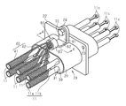
- the wire harness 10 is routed to, for example, a hybrid vehicle or an electric vehicle, and electrically connects one device 91 and a plurality (three in the present embodiment) of devices (not shown). Connecting.
- the wire harness 10 includes a plurality of (six in this embodiment) electric wires 11, a pair of connectors 20 into which both ends of the electric wires 11 are respectively inserted, and some or all of the plurality of electric wires 11. And at least one flexible protective tube 12.
- six electric wires 11 are divided into three protective tubes 12 and are accommodated, for example, two by two.
- the protective tube 12 is a corrugated tube made of, for example, a synthetic resin material.
- the connector 20 corresponds to a cylindrical member according to the present invention.
- each electric wire 11 has a core wire 11a and a cylindrical insulating coating 11b covering the outer periphery of the core wire 11a.
- the core wire 11a is a stranded wire formed by twisting together a plurality of metal strands made of, for example, a copper alloy.
- the insulating coating 11b is made of an electrically insulating synthetic resin material.
- a terminal 11c connected to the device 91 is fixed to the end of the core wire 11a.
- the terminal 11c is not intended to be limited, but may be a so-called round terminal.
- illustration of the protective tube 12 is abbreviate
- the configuration of the connector 20 will be described.
- the axial direction of the connector 20 may be simply referred to as the axial direction.
- the connector 20 is attached to a housing (not shown) of the device 91, and is provided in the central portion in the axial direction of the long cylindrical body 21 and the outer peripheral surface of the body 21.
- the flange 22 is provided.
- the connector 20 is integrally formed of a metal material such as an aluminum alloy.
- the flange 22 is provided with an attachment hole 23 for attachment to the device 91.
- a rectangular columnar support member 30 is inserted into the main body 21.
- the support member 30 is made of an elastic material such as rubber.
- the outer peripheral surface of the support member 30 and the inner peripheral surface of the main body 21 are in close contact with each other. Thereby, the space between the support member 30 and the main body portion 21 is sealed.
- the support member 30 is provided with a plurality of through holes 31 extending in the axial direction.
- six through holes 31 are provided in accordance with the number of electric wires 11.
- the electric wire 11 is inserted through each through hole 31.
- the outer peripheral surface of the electric wire 11 (specifically, the insulating coating 11b) and the inner peripheral surface of the through hole 31 are in close contact. Thereby, the space
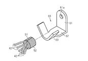
- a terminal member 60 called a so-called open barrel terminal is fixed to the seat portion 24 of the connector 20 via a screw 70.
- the terminal member 60 of the present embodiment is made of a conductive metal material such as an aluminum alloy.
- the terminal member 60 extends in the radial direction of the connector 20, and is bent at the base portion 61 in contact with the seat portion 24, and at the base portion 61 side of the connector 20 at the base portion 61.
- An extending portion 62 extending toward the side away from the flange 22 in the axial direction, and a barrel portion 63 connected to the extending portion 62.
- the base 61 is provided with an insertion hole 61 a through which the screw 70 is inserted.
- the wire harness 10 includes a plurality of shield members 40 each having a cylindrical portion 41 that covers a portion of the electric wire 11 located outside the connector 20.
- the shield member 40 is made of a braided wire in which conductive strands made of an aluminum alloy or the like are knitted into a cylindrical shape.
- the wire harness 10 of the present embodiment includes a number of shield members 40 corresponding to the number of electric wires 11. That is, one electric wire 11 is inserted through the cylindrical portion 41 of one shield member 40.
- An extending portion 42 that extends toward the connector 20 is provided at one end of the cylindrical portion 41 of each shield member 40.
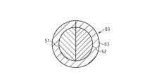
- Three extending portions 42 of the six shield members 40 are preliminarily gathered, and the first collecting portion 51 formed in a half columnar shape and the other three extending portions 42 are preliminarily gathered into a half circle.
- the second aggregated portion 52 formed in a columnar shape is crimped to the barrel portion 63 that forms the cylindrical shape of the terminal member 60 in a state of being attached to each other and gathered into a columnar shape.
- the wire harness 10 includes a cylindrical metal connector 20, a plurality of electric wires 11 inserted through the connector 20, and a braided wire in which conductive strands are knitted into a cylinder.
- a plurality of shield members 40 each having a cylindrical portion 41 that covers a portion of the electric wire 11 located outside the connector 20 are provided.
- the extending portions 42 provided at one end portions of the shield members 40 are fixed to the connector 20 in a state where they are gathered.
- the attaching operation of the shield member 40 to the connector 20 is simplified as compared with the configuration in which the extending portions 42 of the respective shield members 40 are separately fixed to the connector 20. Therefore, the plurality of shield members 40 can be easily attached to the connector 20.
- the extending portion 42 provided at one end of the plurality of shield members 40 is fixed to the connector 20 via the conductive terminal member 60.
- the extended portion 42 of each shield member 40 is fixed to the terminal member 60, and the terminal member 60 is fixed to the connector 20, thereby fixing the extended portion 42 of each shield member 40 to the connector 20. be able to.
- the attaching operation of the shield member 40 to the connector 20 is simplified as compared with the aspect in which the extending portion 42 of each shield member 40 is directly fixed to the connector 20 by soldering or the like.
- the extending portion 42 provided at one end of the plurality of shield members 40 is pressure-bonded to the terminal member 60.
- the extended portion 42 of each shield member 40 is fixed to the terminal member 60 by crimping the extended portion 42 of each shield member 40 together with the terminal member 60. For this reason, the fixing work of the extended portion 42 of each shield member 40 and the terminal member 60 is simplified.
- the second collecting portion 52 in which the portions 42 are gathered together is crimped to the terminal member 60 in a gathered state.
- the terminal member 60 is fixed to the seat portion 24 of the connector 20 via the screw 70. According to such a configuration, the terminal member 60 can be easily fixed to the connector 20 by a simple mode in which the terminal member 60 is fixed to the connector 20 with the screw 70.
- the fixing mode of the terminal member 60 with respect to the connector 20 is not limited to that via the screw 70.
- Other fixing modes such as soldering and welding can also be employed.
- the seat portion 24 can be omitted.
- the terminal member 60 is not limited to the so-called open barrel terminal exemplified in the above embodiment, and may be a closed barrel terminal having a cylindrical barrel portion.
- the extended portion 42 provided at one end portion of each shield member 40 is exemplified as the first aggregated portion 51 or the second aggregated portion 52, but all the shield members 40
- the extending part 42 may be gathered together in advance. Note that the shape in which the extending portions 42 of each shield member 40 are gathered is not limited to a cylindrical shape, and can be changed to any shape such as a prismatic shape.
- each shield member 40 and the terminal member 60 is not limited to crimping
- Other fixing modes such as soldering and welding can be employed.
- -It can also be fastened and fixed by metal caulking etc. in the state where the part where one end part of each shield member 40 was put together was along the outer peripheral surface of connector 20.
- the gathered portions of the shield members 40 can be stably fastened to the connector 20.
- a portion where one end portions of the shield members 40 are gathered with respect to the connector 20 may be directly fixed by soldering or welding.
- a plurality of electric wires 11 may be covered with the cylindrical portion 41 of one shield member 40.
- the cylindrical member is embodied as the connector 20 provided at the end of the electric wire 11, but the cylindrical member according to the present invention is not limited to this, and is provided at the central portion in the length direction of the electric wire 11. It may be embodied as provided.
- the first collecting portion 51 is, for example, a halved cylinder at the distal end portion of the extending portion 42 of the first subset (for example, three shielding members 40) of the plurality of shielding members 40. It may be called the 1st conductive block formed by shape
- the second aggregated portion 52 has a second predetermined shape that can be, for example, a half cylinder, at the distal end portion of the extended portion 42 of the second subset (for example, the remaining three shield members 40) of the plurality of shield members 40. It may be called the 2nd conductive block formed by shape
- a caulking portion formed by combining a plurality of conductive blocks including the first and second conductive blocks (51, 52) and caulked by the barrel portion 63 has a third predetermined shape which may be a columnar shape. Sometimes referred to as a single terminal conductive block or terminal large diameter.
- the plurality of shield members 40 are electrically connected to the main body portion 21 of the connector 20 via the terminal member 60 and the seat portion 24.
- the first predetermined shape of the first conductive block and the second predetermined shape of the second conductive block may be the same, but may be different.
- the third predetermined shape of the single terminal conductive block may be different from the first and second predetermined shapes of the first and second conductive blocks, but may be the same.
- the main body 21 of the connector 20 may be called a connector housing or a connector hood.
- the base 61 and the extension 62 of the terminal member 60 may be referred to as an L-shaped bracket of the terminal member 60.
- the base portion 61 may be referred to as a flat plate-like bent piece that is bent with respect to the extending portion 62.
- a wire harness (10) according to some mounting examples is made of a metal cylindrical connector hood (21) and a plurality of wires (11) inserted through the connector hood (21).
- Each of the electric wires (11) includes a first length portion covered with the connector hood (21) and a second length portion not covered with the connector hood (21).
- the plurality of flexible shield members (40) covering each of the second length portions not present, the plurality of flexible shield members (40), and the connector hood (21) are fixedly connected and electrically Single to connect to A terminal member (60), and one end of each of the plurality of flexible shield members (40) does not cover the outer surface of the corresponding electric wire (11), and is away from the outer surface of the corresponding electric wire (11).
- the one end portions of the plurality of flexible shield members (40) are grouped into a single terminal conductive block, and the single terminal conductive block is the single terminal conductive block.
- One terminal member (60) is fixedly and electrically connected to the connector hood (21).
- the tip portion of the first subset of the first predetermined number of shield members (40) among the plurality of shield members (40) is formed into the first conductive block.
- the tip portion of the second subset consisting of the second predetermined number of shield members (40) of the plurality of shield members (40) is integrated with the second conductive block.
- the single terminal conductive block is a large terminal end portion formed by combining the first conductive block and the second conductive block.
- the single terminal member (60) includes an L-shaped bracket (61, 61) for fixing the single terminal member (60) to the connector hood (21). 62) and a barrel part (63) for caulking the single terminal conductive block.
- the L-shaped brackets (61, 62) of the single terminal member (60) have a flat plate-like extension (in contact with the outer surface of the connector hood (21)). 62) and a flat bent piece (61) which is bent with respect to the flat extension portion (62) and protrudes in a direction orthogonal to the outer surface of the connector hood (21).
Landscapes
- Engineering & Computer Science (AREA)
- Textile Engineering (AREA)
- Physics & Mathematics (AREA)
- Electromagnetism (AREA)
- Microelectronics & Electronic Packaging (AREA)
- Details Of Connecting Devices For Male And Female Coupling (AREA)
- Connections Effected By Soldering, Adhesion, Or Permanent Deformation (AREA)
- Shielding Devices Or Components To Electric Or Magnetic Fields (AREA)
- Insulated Conductors (AREA)
- Details Of Indoor Wiring (AREA)
Priority Applications (2)
| Application Number | Priority Date | Filing Date | Title |
|---|---|---|---|
| US16/980,777 US11335476B2 (en) | 2018-03-30 | 2019-03-11 | Wire harness |
| CN201980018454.2A CN111837202B (zh) | 2018-03-30 | 2019-03-11 | 线束 |
Applications Claiming Priority (2)
| Application Number | Priority Date | Filing Date | Title |
|---|---|---|---|
| JP2018-069922 | 2018-03-30 | ||
| JP2018069922A JP6819641B2 (ja) | 2018-03-30 | 2018-03-30 | ワイヤハーネス |
Publications (1)
| Publication Number | Publication Date |
|---|---|
| WO2019188163A1 true WO2019188163A1 (ja) | 2019-10-03 |
Family
ID=68061593
Family Applications (1)
| Application Number | Title | Priority Date | Filing Date |
|---|---|---|---|
| PCT/JP2019/009570 Ceased WO2019188163A1 (ja) | 2018-03-30 | 2019-03-11 | ワイヤハーネス |
Country Status (4)
| Country | Link |
|---|---|
| US (1) | US11335476B2 (https=) |
| JP (1) | JP6819641B2 (https=) |
| CN (1) | CN111837202B (https=) |
| WO (1) | WO2019188163A1 (https=) |
Families Citing this family (3)
| Publication number | Priority date | Publication date | Assignee | Title |
|---|---|---|---|---|
| JP2024032240A (ja) * | 2022-08-29 | 2024-03-12 | 住友電装株式会社 | ワイヤハーネス |
| JP7806746B2 (ja) * | 2023-03-14 | 2026-01-27 | 住友電装株式会社 | ワイヤハーネス |
| JP2025139217A (ja) * | 2024-03-12 | 2025-09-26 | 住友電装株式会社 | ワイヤハーネス |
Citations (3)
| Publication number | Priority date | Publication date | Assignee | Title |
|---|---|---|---|---|
| JP2004319196A (ja) * | 2003-04-15 | 2004-11-11 | Auto Network Gijutsu Kenkyusho:Kk | シールド接続構造 |
| JP2008041479A (ja) * | 2006-08-08 | 2008-02-21 | Gs Eletech:Kk | 編組シールド被覆電線の保持装置 |
| JP2012234761A (ja) * | 2011-05-09 | 2012-11-29 | Sumitomo Electric Ind Ltd | ケーブルの製造方法およびケーブル |
Family Cites Families (8)
| Publication number | Priority date | Publication date | Assignee | Title |
|---|---|---|---|---|
| JP3346313B2 (ja) * | 1999-01-11 | 2002-11-18 | 住友電装株式会社 | シールド用編み線のアース接続構造 |
| JP2004172476A (ja) * | 2002-11-21 | 2004-06-17 | Auto Network Gijutsu Kenkyusho:Kk | シールド機能を備えた導電路 |
| JP4511988B2 (ja) | 2005-04-27 | 2010-07-28 | 株式会社オートネットワーク技術研究所 | シールド導電路 |
| KR101538806B1 (ko) * | 2009-03-16 | 2015-07-22 | 타이코에이엠피(유) | 차폐용 편조선의 쉘커버 |
| JP5766644B2 (ja) * | 2012-03-26 | 2015-08-19 | 株式会社フジクラ | 編組シールド電線の接続構造及びシールドワイヤハーネスの製造方法 |
| JP5915515B2 (ja) * | 2012-12-25 | 2016-05-11 | 日立金属株式会社 | ワイヤハーネス、及びシールドシェルと編組シールドとの接続構造 |
| WO2018056460A1 (ja) * | 2016-09-26 | 2018-03-29 | 古河電気工業株式会社 | 電磁シールド構造およびワイヤハーネス |
| CN211700805U (zh) * | 2020-02-29 | 2020-10-16 | 一汽解放汽车有限公司 | 一种线束屏蔽层搭接装置 |
-
2018
- 2018-03-30 JP JP2018069922A patent/JP6819641B2/ja active Active
-
2019
- 2019-03-11 CN CN201980018454.2A patent/CN111837202B/zh active Active
- 2019-03-11 US US16/980,777 patent/US11335476B2/en active Active
- 2019-03-11 WO PCT/JP2019/009570 patent/WO2019188163A1/ja not_active Ceased
Patent Citations (3)
| Publication number | Priority date | Publication date | Assignee | Title |
|---|---|---|---|---|
| JP2004319196A (ja) * | 2003-04-15 | 2004-11-11 | Auto Network Gijutsu Kenkyusho:Kk | シールド接続構造 |
| JP2008041479A (ja) * | 2006-08-08 | 2008-02-21 | Gs Eletech:Kk | 編組シールド被覆電線の保持装置 |
| JP2012234761A (ja) * | 2011-05-09 | 2012-11-29 | Sumitomo Electric Ind Ltd | ケーブルの製造方法およびケーブル |
Also Published As
| Publication number | Publication date |
|---|---|
| US20210012923A1 (en) | 2021-01-14 |
| CN111837202B (zh) | 2022-09-02 |
| US11335476B2 (en) | 2022-05-17 |
| JP2019179735A (ja) | 2019-10-17 |
| JP6819641B2 (ja) | 2021-01-27 |
| CN111837202A (zh) | 2020-10-27 |
Similar Documents
| Publication | Publication Date | Title |
|---|---|---|
| JP3786594B2 (ja) | 電磁波シールド編組 | |
| US10964456B2 (en) | Grommet and wire harness | |
| WO2019188163A1 (ja) | ワイヤハーネス | |
| WO2019188231A1 (ja) | ワイヤハーネス | |
| KR101480660B1 (ko) | 보호구, 보호구의 제조 방법 및 쉴드 도전체 | |
| JPWO2018190096A1 (ja) | ワイヤハーネス | |
| JP2017117863A (ja) | シールド導電路 | |
| JP5323755B2 (ja) | 鞘管構造及びワイヤーハーネス | |
| WO2019188938A1 (ja) | ワイヤハーネス | |
| US12243665B2 (en) | Wire harness | |
| CN109644583B (zh) | 电磁屏蔽部件及导电路径 | |
| WO2014148446A1 (ja) | 電線のシールド構造 | |
| JP2015176887A (ja) | 電磁シールド部材およびワイヤハーネス | |
| WO2019216227A1 (ja) | シールド電線の端末構造 | |
| WO2018173784A1 (ja) | 導電線 | |
| JP2017120917A (ja) | シールド導電路 | |
| JP2013122896A (ja) | 電線のシールドコネクタ接続構造 | |
| JP2015188023A (ja) | 電磁シールド部材 | |
| JP6784940B2 (ja) | 導電路 | |
| JP6578228B2 (ja) | 編組導体とシールドシェルの接続構造、コネクタ付き電線、及び、編組導体とシールドシェルの接続方法 | |
| JP6281524B2 (ja) | ワイヤハーネス | |
| JP2003109707A (ja) | 簡易電磁波シールド構造およびその組立治具 | |
| JP2018101578A (ja) | 電線 | |
| JP2024109335A (ja) | シールド電線 | |
| JP2024135055A (ja) | ワイヤハーネス及び電線保護部材 |
Legal Events
| Date | Code | Title | Description |
|---|---|---|---|
| 121 | Ep: the epo has been informed by wipo that ep was designated in this application |
Ref document number: 19774956 Country of ref document: EP Kind code of ref document: A1 |
|
| 122 | Ep: pct application non-entry in european phase |
Ref document number: 19774956 Country of ref document: EP Kind code of ref document: A1 |