WO2019187330A1 - 回転機械 - Google Patents
回転機械 Download PDFInfo
- Publication number
- WO2019187330A1 WO2019187330A1 PCT/JP2018/043062 JP2018043062W WO2019187330A1 WO 2019187330 A1 WO2019187330 A1 WO 2019187330A1 JP 2018043062 W JP2018043062 W JP 2018043062W WO 2019187330 A1 WO2019187330 A1 WO 2019187330A1
- Authority
- WO
- WIPO (PCT)
- Prior art keywords
- cavity
- fin
- radial length
- steam
- diameter portion
- Prior art date
- Legal status (The legal status is an assumption and is not a legal conclusion. Google has not performed a legal analysis and makes no representation as to the accuracy of the status listed.)
- Ceased
Links
Images


Classifications
-
- F—MECHANICAL ENGINEERING; LIGHTING; HEATING; WEAPONS; BLASTING
- F16—ENGINEERING ELEMENTS AND UNITS; GENERAL MEASURES FOR PRODUCING AND MAINTAINING EFFECTIVE FUNCTIONING OF MACHINES OR INSTALLATIONS; THERMAL INSULATION IN GENERAL
- F16D—COUPLINGS FOR TRANSMITTING ROTATION; CLUTCHES; BRAKES
- F16D11/00—Clutches in which the members have interengaging parts
- F16D11/02—Clutches in which the members have interengaging parts disengaged by a contact of a part mounted on the clutch with a stationarily-mounted member
-
- F—MECHANICAL ENGINEERING; LIGHTING; HEATING; WEAPONS; BLASTING
- F16—ENGINEERING ELEMENTS AND UNITS; GENERAL MEASURES FOR PRODUCING AND MAINTAINING EFFECTIVE FUNCTIONING OF MACHINES OR INSTALLATIONS; THERMAL INSULATION IN GENERAL
- F16J—PISTONS; CYLINDERS; SEALINGS
- F16J15/00—Sealings
- F16J15/44—Free-space packings
- F16J15/447—Labyrinth packings
Definitions
- the present invention relates to a rotating machine in which a sealing device for preventing fluid leakage between a stationary side and a rotating side is arranged.
- a steam turbine is configured such that a rotor is rotatably supported by a bearing in a casing, and a plurality of stages of moving blades are fixed to the rotor, while a plurality of stages of stationary blades are fixed to the casing. Then, the steam is supplied from the supply port of the casing and passes through the plurality of moving blades and the stationary blades, so that the rotor is driven and rotated through each of the moving blades and discharged to the outside from the discharge port.
- a seal device is provided between the casing and the rotor in order to prevent an axial leakage flow of steam between the casing and the rotor.
- a labyrinth seal is generally applied as a sealing device.
- the labyrinth seal is configured by providing a plurality of seal fins on the inner surface of the casing. A pressure loss is generated by forming a gap between each seal fin and the rotor, and the leakage flow of the fluid in the axial direction is suppressed by this pressure loss.
- Patent Document 1 An example of such a sealing device is described in Patent Document 1 below.
- the labyrinth seal described in Patent Document 1 is arranged so that a rotating body having a convex portion and a concave portion formed on the outer periphery and a seal ring provided with a fin-like seal member on the inner periphery face each other. is there.
- the tip of the long seal fin in the seal ring faces the concave portion of the rotating body
- the tip of the short seal fin faces the convex portion of the rotating body. Therefore, when the fluid flows in the axial direction between the seal ring and the rotating body from the high pressure side to the low pressure side, the fluid that has passed through the gap between the tip of the long seal fin and the concave portion of the rotating body Flows to the outside in the radial direction by the wall surface of the convex part, and a vortex is formed when the convex part is separated from the convex part. Controls fluid leakage.
- the present invention solves the above-described problems, and an object of the present invention is to provide a rotating machine that improves the sealing performance by optimizing the shape of the cavity surrounded by the seal fin between the stationary body and the rotating body.
- a rotating machine is a rotating machine in which a sealing device that suppresses the axial flow of fluid is arranged between a rotating body and a stationary body.
- Small-diameter portions and large-diameter portions that are alternately provided in the direction, long fins that are alternately provided on the inner peripheral portion of the sealing device at predetermined intervals in the axial direction and that face the radial direction of the small-diameter portion, and the large-diameter portion
- a short fin facing the radial direction of the diameter portion, and the inner diameter of the seal device on the upstream side of the axial flow of fluid from the short fin is smaller than the seal on the downstream side of the axial flow of fluid from the short fin It is characterized by being set larger than the inner diameter of the apparatus.
- the fluid flowing between the two flows through the gap between the outer peripheral surface of the small diameter portion and the tip of the long fin and collides with the wall surface of the large diameter portion. Flows radially outward. Since the fluid flowing outside in the radial direction forms a vortex when separating from the outer peripheral surface of the large diameter portion, a contracted flow is generated in the vicinity of the gap between the tip of the short fin and the outer peripheral surface of the large diameter portion, Fluid leakage from the gap between the outer peripheral surface of the large diameter portion and the tip of the short fin is suppressed.
- the inner diameter of the sealing device on the upstream side of the axial flow of the fluid is set larger than the short fin, the fluid does not easily come into contact with the inner peripheral surface of the stationary body, and the formation of the vortex is not hindered.
- the fluid leakage from the gap between the outer peripheral surface of the large diameter portion and the tip of the short fin can be appropriately suppressed. As a result, it is possible to improve the sealing performance by optimizing the shape of the cavity surrounded by the seal fin between the stationary body and the rotating body.
- a cavity having a concave shape is provided between the long fin and the short fin in the inner peripheral portion of the sealing device, and the first end of the axial flow of the fluid upstream of the short fin.
- the radial length of one cavity is larger than the radial length of the second cavity on the downstream side of the axial flow of fluid from the short fin.
- the radial length of the first cavity upstream of the short fin is set to be larger than the radial length of the second cavity downstream of the short fin, the fluid flowing radially outward in the first cavity It becomes difficult to come into contact with the bottom surface of the first cavity, and a vortex can be formed appropriately, and fluid leakage from the gap between the outer peripheral surface of the large diameter portion and the tip of the short fin can be appropriately suppressed.
- the first cavity has a curved shape along the axial direction.
- the first cavity has a curved shape along the axial direction, the fluid flowing radially outside in the first cavity flows along the bottom surface of the first cavity having the curved shape, so that the vortex can be appropriately generated. Can be formed.
- the radial length Da of the difference between the radial length D1 of the first cavity and the radial length D2 of the second cavity is: W ⁇ (1/3) ⁇ Da ⁇ W ⁇ 2 It is characterized by being set to.
- the radial length of the first cavity is set to an optimum range, a vortex can be appropriately formed by the fluid flowing through the first cavity.
- the radial length Da of the difference between the radial length D1 of the first cavity and the radial length D2 of the second cavity is: W ⁇ (1/3) ⁇ Da ⁇ W ⁇ (2/3) It is characterized by being set to.
- the radial length of the first cavity is set to an optimum range, a vortex can be appropriately formed by the fluid flowing through the first cavity.
- the ratio of the radial length D1 of the first cavity to the total value of the radial length D1 of the first cavity and the radial length D3 of the large diameter portion is: D1 / (D1 + D3)> 1/2 It is characterized by being set to.
- the sealing performance can be improved by optimizing the shape of the cavity surrounded by the seal fin between the stationary body and the rotating body.
- FIG. 1 is a cross-sectional view illustrating the sealing device of the present embodiment.
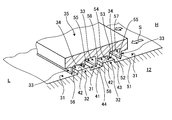
- FIG. 2 is a schematic perspective view showing the sealing device.
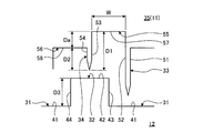
- FIG. 3 is a schematic diagram for explaining the dimensional relationship of the sealing device.
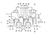
- FIG. 4 is a cross-sectional view illustrating a first modification of the sealing device of the present embodiment.
- FIG. 5 is a cross-sectional view illustrating a second modification of the sealing device of the present embodiment.
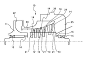
- FIG. 6 is a schematic diagram showing a steam turbine as the rotating machine of the present embodiment.
- FIG. 6 is a schematic diagram showing a steam turbine as a rotating machine of the present embodiment.
- the steam turbine 10 includes a casing 11, a rotor (rotating shaft) 12, a stationary blade 13, a moving blade 14, a bearing 15, and a sealing device 16.
- the casing 11 has a hollow shape, and the rotor 12 is disposed along the horizontal direction.
- a plurality of stationary blades 13 are fixed to the inner peripheral portion of the casing 11 with a predetermined interval in the axial direction of the rotor 12.
- a plurality of rotor disks 21 are fixed to the outer periphery of the rotor disk 21 at predetermined intervals in the axial direction, and a plurality of rotor blades 14 are fixed to the outer periphery of each rotor disk 21.
- the stationary blades 13 and the moving blades 14 are alternately arranged along the axial direction of the rotor 12.
- each end of the rotor 12 in the axial direction is rotatably supported by the bearing 15.
- the rotor 12 is provided with a sealing device 16 between each end portion in the axial direction and the casing 11.
- Each sealing device 16 is arranged on the inner side of each bearing 15, that is, on the stationary blade 13 and moving blade 14 side.
- the casing 11 is provided with a steam supply port 22 on one end side in the axial direction, and the steam supply port 22 communicates with a vehicle compartment 24 in which the stationary blades 13 and the moving blades 14 are disposed through a steam passage 23. .
- the vehicle compartment 24 communicates with the steam outlet 26 through the exhaust chamber 25.
- FIG. 1 is a cross-sectional view showing a sealing device of the present embodiment
- FIG. 2 is a schematic perspective view showing the sealing device
- FIG. 3 is a schematic diagram for explaining the dimensional relationship of the sealing device.
- the steam turbine 10 as a rotating machine of the present embodiment includes a rotor 12 as a rotating body, a casing 11 as a stationary body, and a sealing device 16 provided between the rotor 12 and the casing 11.
- the sealing device 16 is provided between the rotor 12 and the casing 11, and suppresses the axial flow of steam (fluid) flowing from the inside of the casing 11 to the outside.
- the sealing device 16 illustrated in FIGS. 1 to 3 is one that is disposed on the steam supply port 22 side in the steam turbine 10.
- the sealing device 16 is provided between the casing 11 and the rotor 12, and the pressure between the casing 11 and the rotor 12 is reduced from the high pressure side H along the axial direction of the rotor 12.
- the flow (leakage) of the steam S flowing on the side L is suppressed.
- the steam turbine 10 is provided with a plurality of small diameter portions 31 and a plurality of large diameter portions 32 on the rotor 12 side.
- the sealing device 16 is provided with a plurality of long fins 33 and a plurality of short fins 34 on the casing 11 side.
- Each small-diameter portion 31 and each long fin 33 face each other in the radial direction
- each large-diameter portion 32 and each short fin 34 face each other in the radial direction.
- the labyrinth seal 35 which comprises the sealing apparatus 16 is provided in the casing 11 side
- the long fin 33 and the short fin 34 are provided in this labyrinth seal 35.
- the rotor 12 is provided with small-diameter portions 31 and large-diameter portions 32 alternately along the axial direction at the end in the axial direction on the outer peripheral portion.
- the rotor 12 has a reference outer peripheral position P1 having a predetermined outer diameter D with respect to the center line O, and the radial positions of the small diameter portion 31 and the large diameter portion 32 are set with reference to the reference outer peripheral position P1.
- the small diameter portion 31 and the large diameter portion 32 have the same length in the axial direction and the same length in the radial direction with respect to the reference outer peripheral position P1, but the small diameter portion 31 and the large diameter portion 32 have the same length.
- the length of the portion 32 in the axial direction may be different, or the radial length with respect to the reference outer peripheral position P1 may be different.
- the rotor 12 includes a first outer peripheral surface 41 that forms the small diameter portion 31, a second outer peripheral surface 42 that forms the large diameter portion 32, and a first wall surface provided on one side in the axial direction with respect to the second outer peripheral surface 42. 43 and a second wall surface 44 provided on the other side in the axial direction with respect to the second outer peripheral surface 42.
- the first outer peripheral surface 41 and the second outer peripheral surface 42 are continuous in the circumferential direction, are parallel to the center line O, and have a constant outer diameter in the circumferential direction.
- the first wall surface 43 and the second wall surface 44 are continuous in the circumferential direction, are perpendicular to the center line O, and have a constant axial position.
- the labyrinth seal 35 has a ring shape and is fixed to the inner peripheral surface of the casing 11.
- long fins 33 and short fins 34 are alternately provided at predetermined intervals in the axial direction of the rotor 12.
- the distal end portion of the long fin 33 faces the outer side in the radial direction with respect to the small diameter portion 31 of the rotor 12, and the distal end portion of the short fin 34 is in the radial direction with respect to the large diameter portion 32 of the rotor 12.
- the labyrinth seal 35 is set to a reference inner peripheral position P2 having a predetermined radial gap G with respect to the reference outer peripheral position P1 of the rotor 12.
- the long fins 33 and the short fins 34 are provided at equal intervals in the axial direction, and have a tapered shape extending toward the center line O of the rotor 12.
- the length of the long fin 33 in the radial direction is long. That is, the long fin 33 has a tip portion extending toward the center line O with respect to the short fin 34.
- the long fins 33 and the short fins 34 may not be provided at equal intervals in the axial direction.
- the long fin 33 has a predetermined gap between the tip and the first outer peripheral surface 41 of the small diameter portion 31, and the short fin 34 has the second fin of the large diameter portion 32 of the rotor 12. A predetermined gap is secured between the outer peripheral surface 42 and the outer peripheral surface 42.
- the long fin 33, the short fin 34, the long fin 33, the short fin 34, and the long fin 33 are compared with the configuration in which the steam S inside the casing 11 flows from the high pressure side H to the low pressure side L.
- the long fin 33 has a first seal surface 51 that faces the high-pressure side H, and a second seal surface 52 that faces the low-pressure side L.
- the short fin 34 has a first seal surface 53 facing the high-pressure side H and a second seal surface 54 facing the low-pressure side L.
- the first seal surfaces 51 and 53 and the second seal surfaces 52 and 54 are continuous in the circumferential direction, are perpendicular to the center line O, and have a constant axial position.
- the labyrinth seal 35 has an inner diameter on the upstream side (high pressure side H) of the axial flow of the steam S from the short fin 34 and an inner diameter on the downstream side (low pressure side L) of the axial flow of the steam S from the short fin 34. It is set large. That is, the labyrinth seal 35 is provided with cavities 55 and 56 having a concave shape between the long fins 33 and the short fins 34 at the inner periphery.
- the first cavity 55 is provided on the high pressure side H from the short fin 34, and the second cavity 56 is provided on the low pressure side L from the short fin 34.
- the radial length of the first cavity 55 on the upstream side (high pressure side H) of the axial flow of the steam S from the short fin 34 is the downstream side (low pressure side L) of the axial flow of the steam S from the short fin 34.
- the first bottom surface 57 and the second bottom surface 58 are continuous in the circumferential direction, are parallel to the center line O, and have a constant inner diameter in the circumferential direction.
- the inner diameter of the first bottom surface 57 is larger than the inner diameter of the second bottom surface 58. Therefore, the length in the radial direction of the long fin 33 from the first bottom surface 57 (or the second bottom surface 58) to the tip portion is the short fin 34 from the first bottom surface 57 (or the second bottom surface 58) to the tip portion. It is longer than the length in the radial direction.
- the radial length from the tip of the short fin 34 to the first bottom surface 57 is defined as the radial length D1 of the first cavity 55, and from the tip of the short fin 34 to the second bottom surface 58.
- the radial length is defined as the radial length D2 of the second cavity 56, and the difference between the radial length D1 of the first cavity 55 and the radial length D2 of the second cavity 56 is the radial length Da. It becomes.
- the axial length of the first cavity 55 is defined as W.
- the radial length Da of the difference between the radial length D1 of the first cavity 55 and the radial length D2 of the second cavity 56 is from 1/3 to 2 in the axial length W of the first cavity 55.
- the radial length of the large diameter portion 32 relative to the small diameter portion 31 is defined as D3. Then, the ratio of the radial length D1 of the first cavity 55 to the total value of the radial length D1 of the first cavity 55 and the radial length D3 of the large diameter portion 32 is larger than 1 ⁇ 2 (50%). It is preferably set. D1 / (D1 + D3)> 1/2
- This vortex of the steam S generates a contracted current in the vicinity of the gap between the tip of the short fin 34 and the second outer peripheral surface 42 of the large diameter portion 32, and the second outer peripheral surface 42 of the large diameter portion 32 and the short fin 34 The leakage of the steam S from the gap with the tip to the second cavity 56 side is suppressed.
- the radial length D1 of the first cavity 55 on the high-pressure side H from the short fin 34 is set to be larger than the radial length D2 of the second cavity 56 on the low-pressure side L, the large-diameter portion 32.
- the steam S that peels from the first wall surface 43 and flows to the outside in the radial direction is less likely to come into contact with the first bottom surface 57 of the first cavity 55, and does not hinder the formation of vortex flow here. Therefore, the contracted flow in the vicinity of the gap between the tip of the short fin 34 and the second outer peripheral surface 42 of the large diameter portion 32 is appropriately generated, and the leakage of the steam S from the gap to the second cavity 56 is appropriately suppressed. Is done.
- the radial length of the second cavity 56 on the low pressure side L from the short fin 34 is set smaller than the radial length of the first cavity 55 on the high pressure side H, the volume of the second cavity 56 is reduced. can do. Therefore, the speed of the steam S flowing into the second cavity 56 through the gap between the tip of the short fin 34 and the second outer peripheral surface 42 of the large diameter portion 32 does not decrease, and the long fin 33 has a predetermined speed.
- the first seal surface 51 is collided, and an appropriate vortex flow is generated in the space outside the small diameter portion 31.
- the vortex of the steam S generates a contracted current in the vicinity of the gap between the tip of the long fin 33 and the first outer peripheral surface 41 of the small diameter portion 31, and the first outer peripheral surface 41 of the small diameter portion 31 and the long fin. The leakage of the steam S from the gap with the tip of 33 to the first cavity 55 side is suppressed.
- FIG. 4 is a cross-sectional view illustrating a first modification of the sealing device of the present embodiment
- FIG. 5 is a cross-sectional view illustrating a second modification of the sealing device of the present embodiment.
- the labyrinth seal 35 has long fins 33 and short fins 34 alternately arranged at predetermined intervals in the axial direction of the rotor 12 on the inner peripheral portion.
- the front end of the long fin 33 faces the outer side in the radial direction with respect to the small diameter part 31 of the rotor 12, and the front end of the short fin 34 is in the radial direction with respect to the large diameter part 32 of the rotor 12. It faces the outside.
- the long fin 33 has a first seal surface 51 that faces the high-pressure side H, and a second seal surface 52 that faces the low-pressure side L.
- the short fin 34 has a first seal surface 53 facing the high-pressure side H and a second seal surface 54 facing the low-pressure side L.
- the labyrinth seal 35 has an inner diameter on the upstream side (high pressure side H) of the axial flow of the steam S from the short fin 34 and an inner diameter on the downstream side (low pressure side L) of the axial flow of the steam S from the short fin 34. It is set large. That is, the labyrinth seal 35 is provided with cavities 61 and 56 having a concave shape between the long fins 33 and the short fins 34 at the inner periphery. The first cavity 61 is provided on the high pressure side H from the short fin 34, and the second cavity 56 is provided on the low pressure side L from the short fin 34.
- the radial length of the first cavity 61 on the upstream side (high pressure side H) of the axial flow of the steam S from the short fin 34 is the downstream side (low pressure side L) of the axial flow of the steam S from the short fin 34.
- the first curved bottom surface 62 has a curved shape along the axial direction, and has an inner diameter larger than the inner diameter of the second bottom surface 58.
- the labyrinth seal 35 has a short inner diameter on the upstream side (high pressure side H) of the axial flow of the steam S from the short fin 34. It is set larger than the inner diameter at the downstream side (low pressure side L) of the axial flow of the steam S from the fin 34. That is, the labyrinth seal 35 is provided with cavities 65 and 56 having a concave shape between the long fins 33 and the short fins 34 at the inner periphery.
- the first cavity 65 is provided on the high pressure side H from the short fin 34, and the second cavity 56 is provided on the low pressure side L from the short fin 34.
- the radial length of the first cavity 65 on the upstream side (high pressure side H) of the axial flow of the steam S from the short fin 34 is the downstream side (low pressure side L) of the axial flow of the steam S from the short fin 34.
- the first seal surface 51 and the second bottom surface 58 are included.
- the first bottom surface 66 has a larger inner diameter than the inner diameter of the second bottom surface 58.
- a part or the whole of the first cavity is curved, but a part or the whole of the second cavity may be curved.
- the small-diameter portions 31 and the large-diameter portions 32 provided alternately in the axial direction on the outer peripheral portion of the rotor 12 and the inner peripheral portion of the seal device 16 (labyrinth seal 35).
- a long fin 33 provided alternately with a predetermined interval in the axial direction and opposed to the radial direction of the small diameter portion 31 and a short fin 34 opposed to the radial direction of the large diameter portion 32 are provided.
- the inner diameter of the labyrinth seal 35 on the upstream side of the axial flow is set larger than the inner diameter of the labyrinth seal 35 on the downstream side of the axial flow of the steam S from the short fin 34.
- the steam S flowing between the two flows through the gap between the first outer peripheral surface 41 of the small diameter portion 31 and the tip of the long fin 33 to the low pressure side L. , It collides with the first wall surface 43 of the large diameter portion 32 and flows outward in the radial direction.
- the steam S flowing outward in the radial direction forms a vortex when separating from the second outer peripheral surface 42 of the large-diameter portion 32, so that the tip of the short fin 34 and the second outer peripheral surface 42 of the large-diameter portion 32 are formed.
- a contracted flow is generated in the vicinity of the gap, and leakage of the steam S from the gap between the second outer peripheral surface 42 of the large diameter portion 32 and the tip of the short fin 34 is suppressed.
- the inner diameter of the labyrinth seal 35 on the upstream side of the short fin 34 is set to be large, the steam S does not easily contact the inner peripheral surface of the labyrinth seal 35 and does not hinder the formation of vortex flow.
- the leakage of the steam S from the gap between the second outer peripheral surface 42 of the diameter portion 32 and the tip of the short fin 34 can be appropriately suppressed.
- the sealing performance can be improved by optimizing the shape of the first cavity 55 (61, 65) surrounded by the fins 33, 34 between the casing 11 and the rotor 12.
- a cavity 55 (61, 65) having a concave shape is provided between the long fin 33 and the short fin 34 at the inner peripheral portion of the labyrinth seal 35, and the shaft of the steam S is provided by the short fin 34.
- the radial length of the first cavity 55 (61, 65) on the upstream side of the directional flow is made larger than the radial length of the second cavity 56 on the downstream side of the axial flow of the steam S from the short fin 34. Therefore, the steam S flowing radially outward in the first cavity 55 (61, 65) is less likely to contact the first bottom surface 57 of the first cavity 55 (61, 65), and an appropriate vortex can be formed. It is possible to appropriately suppress the leakage of the steam S from the gap between the second outer peripheral surface 42 of the large diameter portion 32 and the tip of the short fin 34.
- the first cavity 61 has a curved shape along the axial direction. Accordingly, the steam S flowing radially outward in the first cavity 61 flows along the first curved bottom surface 62 of the first cavity 61 having a curved shape, so that a vortex can be appropriately formed.
- the radial length that is the difference between the radial length of the first cavity 55 (61, 65) and the radial length of the second cavity 56 is set to the first cavity 55 (61, 65). It is set in the range of 1/3 to 2 of the axial length.
- the radial length of the difference between the radial length of the first cavity 55 (61, 65) and the radial length of the second cavity 56 is set to the axial length of the first cavity 55 (61, 65). It is set within the range of 1/3 to 2/3. Accordingly, the vortex can be appropriately formed by the steam S flowing through the first cavity 55 (61, 65).
- the radial length of the first cavity 55 (61, 65) with respect to the total value of the radial length of the first cavity 55 (61, 65) and the radial length of the large diameter portion 32 is determined.
- the ratio is set larger than 1/2. Accordingly, the vortex can be appropriately formed by the steam S flowing through the first cavity 55 (61, 65).
- the casing 11 having a hollow shape, the rotor 12 to which the moving blade 14 is fixed and rotatably supported in the casing 11, and the axial direction of the casing 11 and the rotor 12 And a sealing device 16 disposed between the two ends.
- the steam S flowing between the two flows through the gap between the first outer peripheral surface 41 of the small diameter portion 31 and the tip of the long fin 33 to the low pressure side L. , It collides with the first wall surface 43 of the large diameter portion 32 and flows outward in the radial direction.
- the steam S flowing outward in the radial direction forms a vortex when separating from the second outer peripheral surface 42 of the large-diameter portion 32, so that the tip of the short fin 34 and the second outer peripheral surface 42 of the large-diameter portion 32 are formed.
- a contracted flow is generated in the vicinity of the gap, and leakage of the steam S from the gap between the second outer peripheral surface 42 of the large diameter portion 32 and the tip of the short fin 34 is suppressed.
- the inner diameter of the labyrinth seal 35 on the upstream side of the short fin 34 is set to be large, the steam S does not easily contact the inner peripheral surface of the labyrinth seal 35 and does not hinder the formation of vortex flow.
- the leakage of the steam S from the gap between the second outer peripheral surface 42 of the diameter portion 32 and the tip of the short fin 34 can be appropriately suppressed.
- the sealing performance can be improved by optimizing the shape of the first cavity 55 (61, 65) surrounded by the fins 33, 34 between the casing 11 and the rotor 12.
- the labyrinth seal 35 is fixed to the inner peripheral portion of the casing 11, and the long fin 33 and the short fin 34, the first cavity 55 (61, 65), and the first Although the two cavities 56 are integrally provided, the configuration is not limited to this.
- the long fins 33 and the short fins 34 may be provided as separate members on the inner peripheral portion of the labyrinth seal 35.
- the long fins 33 and the short fins 34 may be fixed to the inner peripheral portion of the casing 11, and the first cavities 55 (61, 65) and the second cavities 56 may be formed.
- the three long fins 33 and the two short fins 34 are provided on the labyrinth seal 35 fixed to the inner peripheral portion of the casing 11. What is necessary is just to set suitably according to the distance of the axial direction to do.
- the rotary machine of the present invention is the steam turbine 10 and the seal device 16 is provided between the rotor 12 and the casing 11, but the present invention is not limited to this configuration.
- a sealing device may be provided between the rotor 12 and the stationary blade 13 or between the seeding 11 and the moving blade 14.
- the rotary machine of the present invention is applied to the steam turbine 10 and has been described as the sealing device 16 disposed at the shaft end portions of the casing 11 and the rotor 12.
- the steam turbine described in this embodiment is used. It is not limited to 10.
- the sealing device of the present invention may be applied to a sealing device disposed between the turbines.
- the sealing device of the present invention is not limited to a steam turbine, and may be applied to a rotary machine such as a compressor or an exhaust turbine that has an internal pressure higher than an external pressure during operation.
Landscapes
- Engineering & Computer Science (AREA)
- General Engineering & Computer Science (AREA)
- Mechanical Engineering (AREA)
- Sealing Using Fluids, Sealing Without Contact, And Removal Of Oil (AREA)
- Turbine Rotor Nozzle Sealing (AREA)
Applications Claiming Priority (2)
| Application Number | Priority Date | Filing Date | Title |
|---|---|---|---|
| JP2018066990A JP2019178700A (ja) | 2018-03-30 | 2018-03-30 | 回転機械 |
| JP2018-066990 | 2018-03-30 |
Publications (1)
| Publication Number | Publication Date |
|---|---|
| WO2019187330A1 true WO2019187330A1 (ja) | 2019-10-03 |
Family
ID=68058677
Family Applications (1)
| Application Number | Title | Priority Date | Filing Date |
|---|---|---|---|
| PCT/JP2018/043062 Ceased WO2019187330A1 (ja) | 2018-03-30 | 2018-11-21 | 回転機械 |
Country Status (2)
| Country | Link |
|---|---|
| JP (1) | JP2019178700A (enExample) |
| WO (1) | WO2019187330A1 (enExample) |
Families Citing this family (1)
| Publication number | Priority date | Publication date | Assignee | Title |
|---|---|---|---|---|
| JP6808872B1 (ja) * | 2020-04-28 | 2021-01-06 | 三菱パワー株式会社 | シール装置及び回転機械 |
Citations (6)
| Publication number | Priority date | Publication date | Assignee | Title |
|---|---|---|---|---|
| JPS58127258U (ja) * | 1982-02-22 | 1983-08-29 | 三菱重工業株式会社 | ラビリンスシ−ル |
| JPS59192803A (ja) * | 1983-04-14 | 1984-11-01 | Mitsubishi Heavy Ind Ltd | 蒸気タ−ビンのグランドシ−リング装置 |
| WO2014077058A1 (ja) * | 2012-11-13 | 2014-05-22 | 三菱重工コンプレッサ株式会社 | 回転機械 |
| WO2016121259A1 (ja) * | 2015-01-27 | 2016-08-04 | 三菱日立パワーシステムズ株式会社 | タービン |
| JP2017145813A (ja) * | 2016-02-19 | 2017-08-24 | 三菱日立パワーシステムズ株式会社 | 回転機械 |
| WO2017209018A1 (ja) * | 2016-05-31 | 2017-12-07 | 株式会社神戸製鋼所 | ラビリンスシール |
-
2018
- 2018-03-30 JP JP2018066990A patent/JP2019178700A/ja active Pending
- 2018-11-21 WO PCT/JP2018/043062 patent/WO2019187330A1/ja not_active Ceased
Patent Citations (6)
| Publication number | Priority date | Publication date | Assignee | Title |
|---|---|---|---|---|
| JPS58127258U (ja) * | 1982-02-22 | 1983-08-29 | 三菱重工業株式会社 | ラビリンスシ−ル |
| JPS59192803A (ja) * | 1983-04-14 | 1984-11-01 | Mitsubishi Heavy Ind Ltd | 蒸気タ−ビンのグランドシ−リング装置 |
| WO2014077058A1 (ja) * | 2012-11-13 | 2014-05-22 | 三菱重工コンプレッサ株式会社 | 回転機械 |
| WO2016121259A1 (ja) * | 2015-01-27 | 2016-08-04 | 三菱日立パワーシステムズ株式会社 | タービン |
| JP2017145813A (ja) * | 2016-02-19 | 2017-08-24 | 三菱日立パワーシステムズ株式会社 | 回転機械 |
| WO2017209018A1 (ja) * | 2016-05-31 | 2017-12-07 | 株式会社神戸製鋼所 | ラビリンスシール |
Also Published As
| Publication number | Publication date |
|---|---|
| JP2019178700A (ja) | 2019-10-17 |
Similar Documents
| Publication | Publication Date | Title |
|---|---|---|
| JP6131177B2 (ja) | シール構造、及び回転機械 | |
| EP3018297B1 (en) | Sealing device and turbo machine | |
| JP6296649B2 (ja) | シール構造、及び回転機械 | |
| WO2017098960A1 (ja) | ステップシール,シール構造,ターボ機械及びステップシールの製造方法 | |
| KR19990063333A (ko) | 비접촉식으로 회전자와 고정자 간에 형성된 분리 갭을 밀봉하기 위한 방법 및 장치 | |
| KR20030035993A (ko) | 환상 시일 링 조립체용 패킹 부품 및 터빈 노즐다이어프램용 환상 시일 링 조립체 | |
| US11136897B2 (en) | Seal device and turbomachine | |
| US11187097B2 (en) | Rotary machine | |
| JP2017106395A (ja) | シール構造及びタービン | |
| JP2019035374A (ja) | 遠心回転機械 | |
| CN103291379B (zh) | 涡轮机 | |
| JP2018115581A (ja) | タービン排気室 | |
| JP2008303766A (ja) | 回転流体機械のシール装置および回転流体機械 | |
| CN113383147B (zh) | 旋转机械 | |
| JP2009036118A (ja) | 軸流排気型タービン | |
| JP7145775B2 (ja) | 回転機械 | |
| WO2018155546A1 (ja) | 遠心圧縮機 | |
| WO2019187330A1 (ja) | 回転機械 | |
| JP2014238066A (ja) | 回転機械 | |
| JP2018135815A (ja) | 遠心回転機械 | |
| CN1330851C (zh) | 无油工作的气动发动机 | |
| JP6167158B2 (ja) | シール構造及びターボ機械 | |
| WO2018181939A1 (ja) | 可変静翼、及び圧縮機 | |
| JP2020165415A (ja) | 回転機械 | |
| JP2018066355A (ja) | インペラ及び回転機械 |
Legal Events
| Date | Code | Title | Description |
|---|---|---|---|
| 121 | Ep: the epo has been informed by wipo that ep was designated in this application |
Ref document number: 18912222 Country of ref document: EP Kind code of ref document: A1 |
|
| 122 | Ep: pct application non-entry in european phase |
Ref document number: 18912222 Country of ref document: EP Kind code of ref document: A1 |