WO2019187315A1 - Dispositif d'alimentation électrique et véhicule électrique équipé d'un dispositif d'alimentation électrique - Google Patents
Dispositif d'alimentation électrique et véhicule électrique équipé d'un dispositif d'alimentation électrique Download PDFInfo
- Publication number
- WO2019187315A1 WO2019187315A1 PCT/JP2018/042379 JP2018042379W WO2019187315A1 WO 2019187315 A1 WO2019187315 A1 WO 2019187315A1 JP 2018042379 W JP2018042379 W JP 2018042379W WO 2019187315 A1 WO2019187315 A1 WO 2019187315A1
- Authority
- WO
- WIPO (PCT)
- Prior art keywords
- power supply
- supply device
- battery
- battery stack
- main body
- Prior art date
Links
Images


Classifications
-
- H—ELECTRICITY
- H01—ELECTRIC ELEMENTS
- H01M—PROCESSES OR MEANS, e.g. BATTERIES, FOR THE DIRECT CONVERSION OF CHEMICAL ENERGY INTO ELECTRICAL ENERGY
- H01M10/00—Secondary cells; Manufacture thereof
- H01M10/60—Heating or cooling; Temperature control
- H01M10/61—Types of temperature control
- H01M10/613—Cooling or keeping cold
-
- B—PERFORMING OPERATIONS; TRANSPORTING
- B60—VEHICLES IN GENERAL
- B60K—ARRANGEMENT OR MOUNTING OF PROPULSION UNITS OR OF TRANSMISSIONS IN VEHICLES; ARRANGEMENT OR MOUNTING OF PLURAL DIVERSE PRIME-MOVERS IN VEHICLES; AUXILIARY DRIVES FOR VEHICLES; INSTRUMENTATION OR DASHBOARDS FOR VEHICLES; ARRANGEMENTS IN CONNECTION WITH COOLING, AIR INTAKE, GAS EXHAUST OR FUEL SUPPLY OF PROPULSION UNITS IN VEHICLES
- B60K1/00—Arrangement or mounting of electrical propulsion units
- B60K1/04—Arrangement or mounting of electrical propulsion units of the electric storage means for propulsion
-
- B—PERFORMING OPERATIONS; TRANSPORTING
- B60—VEHICLES IN GENERAL
- B60L—PROPULSION OF ELECTRICALLY-PROPELLED VEHICLES; SUPPLYING ELECTRIC POWER FOR AUXILIARY EQUIPMENT OF ELECTRICALLY-PROPELLED VEHICLES; ELECTRODYNAMIC BRAKE SYSTEMS FOR VEHICLES IN GENERAL; MAGNETIC SUSPENSION OR LEVITATION FOR VEHICLES; MONITORING OPERATING VARIABLES OF ELECTRICALLY-PROPELLED VEHICLES; ELECTRIC SAFETY DEVICES FOR ELECTRICALLY-PROPELLED VEHICLES
- B60L50/00—Electric propulsion with power supplied within the vehicle
- B60L50/50—Electric propulsion with power supplied within the vehicle using propulsion power supplied by batteries or fuel cells
- B60L50/60—Electric propulsion with power supplied within the vehicle using propulsion power supplied by batteries or fuel cells using power supplied by batteries
- B60L50/64—Constructional details of batteries specially adapted for electric vehicles
-
- H—ELECTRICITY
- H01—ELECTRIC ELEMENTS
- H01M—PROCESSES OR MEANS, e.g. BATTERIES, FOR THE DIRECT CONVERSION OF CHEMICAL ENERGY INTO ELECTRICAL ENERGY
- H01M10/00—Secondary cells; Manufacture thereof
- H01M10/04—Construction or manufacture in general
- H01M10/0481—Compression means other than compression means for stacks of electrodes and separators
-
- H—ELECTRICITY
- H01—ELECTRIC ELEMENTS
- H01M—PROCESSES OR MEANS, e.g. BATTERIES, FOR THE DIRECT CONVERSION OF CHEMICAL ENERGY INTO ELECTRICAL ENERGY
- H01M10/00—Secondary cells; Manufacture thereof
- H01M10/60—Heating or cooling; Temperature control
- H01M10/62—Heating or cooling; Temperature control specially adapted for specific applications
- H01M10/625—Vehicles
-
- H—ELECTRICITY
- H01—ELECTRIC ELEMENTS
- H01M—PROCESSES OR MEANS, e.g. BATTERIES, FOR THE DIRECT CONVERSION OF CHEMICAL ENERGY INTO ELECTRICAL ENERGY
- H01M10/00—Secondary cells; Manufacture thereof
- H01M10/60—Heating or cooling; Temperature control
- H01M10/65—Means for temperature control structurally associated with the cells
- H01M10/655—Solid structures for heat exchange or heat conduction
- H01M10/6554—Rods or plates
-
- H—ELECTRICITY
- H01—ELECTRIC ELEMENTS
- H01M—PROCESSES OR MEANS, e.g. BATTERIES, FOR THE DIRECT CONVERSION OF CHEMICAL ENERGY INTO ELECTRICAL ENERGY
- H01M50/00—Constructional details or processes of manufacture of the non-active parts of electrochemical cells other than fuel cells, e.g. hybrid cells
- H01M50/20—Mountings; Secondary casings or frames; Racks, modules or packs; Suspension devices; Shock absorbers; Transport or carrying devices; Holders
- H01M50/204—Racks, modules or packs for multiple batteries or multiple cells
- H01M50/207—Racks, modules or packs for multiple batteries or multiple cells characterised by their shape
- H01M50/209—Racks, modules or packs for multiple batteries or multiple cells characterised by their shape adapted for prismatic or rectangular cells
-
- H—ELECTRICITY
- H01—ELECTRIC ELEMENTS
- H01M—PROCESSES OR MEANS, e.g. BATTERIES, FOR THE DIRECT CONVERSION OF CHEMICAL ENERGY INTO ELECTRICAL ENERGY
- H01M50/00—Constructional details or processes of manufacture of the non-active parts of electrochemical cells other than fuel cells, e.g. hybrid cells
- H01M50/20—Mountings; Secondary casings or frames; Racks, modules or packs; Suspension devices; Shock absorbers; Transport or carrying devices; Holders
- H01M50/233—Mountings; Secondary casings or frames; Racks, modules or packs; Suspension devices; Shock absorbers; Transport or carrying devices; Holders characterised by physical properties of casings or racks, e.g. dimensions
- H01M50/24—Mountings; Secondary casings or frames; Racks, modules or packs; Suspension devices; Shock absorbers; Transport or carrying devices; Holders characterised by physical properties of casings or racks, e.g. dimensions adapted for protecting batteries from their environment, e.g. from corrosion
-
- H—ELECTRICITY
- H01—ELECTRIC ELEMENTS
- H01M—PROCESSES OR MEANS, e.g. BATTERIES, FOR THE DIRECT CONVERSION OF CHEMICAL ENERGY INTO ELECTRICAL ENERGY
- H01M50/00—Constructional details or processes of manufacture of the non-active parts of electrochemical cells other than fuel cells, e.g. hybrid cells
- H01M50/20—Mountings; Secondary casings or frames; Racks, modules or packs; Suspension devices; Shock absorbers; Transport or carrying devices; Holders
- H01M50/249—Mountings; Secondary casings or frames; Racks, modules or packs; Suspension devices; Shock absorbers; Transport or carrying devices; Holders specially adapted for aircraft or vehicles, e.g. cars or trains
-
- B—PERFORMING OPERATIONS; TRANSPORTING
- B60—VEHICLES IN GENERAL
- B60K—ARRANGEMENT OR MOUNTING OF PROPULSION UNITS OR OF TRANSMISSIONS IN VEHICLES; ARRANGEMENT OR MOUNTING OF PLURAL DIVERSE PRIME-MOVERS IN VEHICLES; AUXILIARY DRIVES FOR VEHICLES; INSTRUMENTATION OR DASHBOARDS FOR VEHICLES; ARRANGEMENTS IN CONNECTION WITH COOLING, AIR INTAKE, GAS EXHAUST OR FUEL SUPPLY OF PROPULSION UNITS IN VEHICLES
- B60K6/00—Arrangement or mounting of plural diverse prime-movers for mutual or common propulsion, e.g. hybrid propulsion systems comprising electric motors and internal combustion engines ; Control systems therefor, i.e. systems controlling two or more prime movers, or controlling one of these prime movers and any of the transmission, drive or drive units Informative references: mechanical gearings with secondary electric drive F16H3/72; arrangements for handling mechanical energy structurally associated with the dynamo-electric machine H02K7/00; machines comprising structurally interrelated motor and generator parts H02K51/00; dynamo-electric machines not otherwise provided for in H02K see H02K99/00
- B60K6/20—Arrangement or mounting of plural diverse prime-movers for mutual or common propulsion, e.g. hybrid propulsion systems comprising electric motors and internal combustion engines ; Control systems therefor, i.e. systems controlling two or more prime movers, or controlling one of these prime movers and any of the transmission, drive or drive units Informative references: mechanical gearings with secondary electric drive F16H3/72; arrangements for handling mechanical energy structurally associated with the dynamo-electric machine H02K7/00; machines comprising structurally interrelated motor and generator parts H02K51/00; dynamo-electric machines not otherwise provided for in H02K see H02K99/00 the prime-movers consisting of electric motors and internal combustion engines, e.g. HEVs
- B60K6/22—Arrangement or mounting of plural diverse prime-movers for mutual or common propulsion, e.g. hybrid propulsion systems comprising electric motors and internal combustion engines ; Control systems therefor, i.e. systems controlling two or more prime movers, or controlling one of these prime movers and any of the transmission, drive or drive units Informative references: mechanical gearings with secondary electric drive F16H3/72; arrangements for handling mechanical energy structurally associated with the dynamo-electric machine H02K7/00; machines comprising structurally interrelated motor and generator parts H02K51/00; dynamo-electric machines not otherwise provided for in H02K see H02K99/00 the prime-movers consisting of electric motors and internal combustion engines, e.g. HEVs characterised by apparatus, components or means specially adapted for HEVs
- B60K6/28—Arrangement or mounting of plural diverse prime-movers for mutual or common propulsion, e.g. hybrid propulsion systems comprising electric motors and internal combustion engines ; Control systems therefor, i.e. systems controlling two or more prime movers, or controlling one of these prime movers and any of the transmission, drive or drive units Informative references: mechanical gearings with secondary electric drive F16H3/72; arrangements for handling mechanical energy structurally associated with the dynamo-electric machine H02K7/00; machines comprising structurally interrelated motor and generator parts H02K51/00; dynamo-electric machines not otherwise provided for in H02K see H02K99/00 the prime-movers consisting of electric motors and internal combustion engines, e.g. HEVs characterised by apparatus, components or means specially adapted for HEVs characterised by the electric energy storing means, e.g. batteries or capacitors
-
- B—PERFORMING OPERATIONS; TRANSPORTING
- B60—VEHICLES IN GENERAL
- B60Y—INDEXING SCHEME RELATING TO ASPECTS CROSS-CUTTING VEHICLE TECHNOLOGY
- B60Y2200/00—Type of vehicle
- B60Y2200/90—Vehicles comprising electric prime movers
- B60Y2200/91—Electric vehicles
-
- B—PERFORMING OPERATIONS; TRANSPORTING
- B60—VEHICLES IN GENERAL
- B60Y—INDEXING SCHEME RELATING TO ASPECTS CROSS-CUTTING VEHICLE TECHNOLOGY
- B60Y2200/00—Type of vehicle
- B60Y2200/90—Vehicles comprising electric prime movers
- B60Y2200/92—Hybrid vehicles
-
- B—PERFORMING OPERATIONS; TRANSPORTING
- B60—VEHICLES IN GENERAL
- B60Y—INDEXING SCHEME RELATING TO ASPECTS CROSS-CUTTING VEHICLE TECHNOLOGY
- B60Y2400/00—Special features of vehicle units
- B60Y2400/11—Electric energy storages
- B60Y2400/112—Batteries
-
- H—ELECTRICITY
- H01—ELECTRIC ELEMENTS
- H01M—PROCESSES OR MEANS, e.g. BATTERIES, FOR THE DIRECT CONVERSION OF CHEMICAL ENERGY INTO ELECTRICAL ENERGY
- H01M2220/00—Batteries for particular applications
- H01M2220/20—Batteries in motive systems, e.g. vehicle, ship, plane
-
- Y—GENERAL TAGGING OF NEW TECHNOLOGICAL DEVELOPMENTS; GENERAL TAGGING OF CROSS-SECTIONAL TECHNOLOGIES SPANNING OVER SEVERAL SECTIONS OF THE IPC; TECHNICAL SUBJECTS COVERED BY FORMER USPC CROSS-REFERENCE ART COLLECTIONS [XRACs] AND DIGESTS
- Y02—TECHNOLOGIES OR APPLICATIONS FOR MITIGATION OR ADAPTATION AGAINST CLIMATE CHANGE
- Y02E—REDUCTION OF GREENHOUSE GAS [GHG] EMISSIONS, RELATED TO ENERGY GENERATION, TRANSMISSION OR DISTRIBUTION
- Y02E60/00—Enabling technologies; Technologies with a potential or indirect contribution to GHG emissions mitigation
- Y02E60/10—Energy storage using batteries
-
- Y—GENERAL TAGGING OF NEW TECHNOLOGICAL DEVELOPMENTS; GENERAL TAGGING OF CROSS-SECTIONAL TECHNOLOGIES SPANNING OVER SEVERAL SECTIONS OF THE IPC; TECHNICAL SUBJECTS COVERED BY FORMER USPC CROSS-REFERENCE ART COLLECTIONS [XRACs] AND DIGESTS
- Y02—TECHNOLOGIES OR APPLICATIONS FOR MITIGATION OR ADAPTATION AGAINST CLIMATE CHANGE
- Y02P—CLIMATE CHANGE MITIGATION TECHNOLOGIES IN THE PRODUCTION OR PROCESSING OF GOODS
- Y02P70/00—Climate change mitigation technologies in the production process for final industrial or consumer products
- Y02P70/50—Manufacturing or production processes characterised by the final manufactured product
-
- Y—GENERAL TAGGING OF NEW TECHNOLOGICAL DEVELOPMENTS; GENERAL TAGGING OF CROSS-SECTIONAL TECHNOLOGIES SPANNING OVER SEVERAL SECTIONS OF THE IPC; TECHNICAL SUBJECTS COVERED BY FORMER USPC CROSS-REFERENCE ART COLLECTIONS [XRACs] AND DIGESTS
- Y02—TECHNOLOGIES OR APPLICATIONS FOR MITIGATION OR ADAPTATION AGAINST CLIMATE CHANGE
- Y02T—CLIMATE CHANGE MITIGATION TECHNOLOGIES RELATED TO TRANSPORTATION
- Y02T10/00—Road transport of goods or passengers
- Y02T10/60—Other road transportation technologies with climate change mitigation effect
- Y02T10/70—Energy storage systems for electromobility, e.g. batteries
Definitions
- the present invention relates to a power supply device in which a plurality of battery cells are stacked, and an electric vehicle such as a hybrid vehicle, a fuel cell vehicle, an electric vehicle, and an electric motorcycle including the power supply device.
- a power supply device in which a plurality of battery cells are stacked to form a battery stack, end plates are arranged on both end faces of the battery stack, and a pair of end plates arranged on both ends are connected by a bind bar.
- the battery stack is fixed in a pressurized state with a pair of end plates, and each battery cell is stacked so as not to be displaced.
- Both ends of the bind bar are connected to the end plate so that the end plate presses the battery stack from both end surfaces.
- the bind bar is bent at both ends of the battery stack to provide bent pieces, and the bent pieces are fixed to the surface of the end plate by screws.
- end plates are arranged on both side surfaces of the battery stack, and bind bars are connected to both sides of the end plate (see Patent Document 1).
- This power supply device is fixed with a binding bar made of an angle material in order to fasten the rectangular battery cells in a stacked state. Both ends of the bind bar are fixed to end plates disposed on both end faces of the stacked rectangular battery cell. In particular, in order to avoid expansion of the rectangular battery cell due to repeated charge and discharge, it is necessary to firmly fasten with the bind bar.
- a power supply device in which a large number of battery cells are stacked needs to be forcibly cooled because the battery cells generate heat due to charge / discharge and the temperature rises.
- the power supply device which arrange
- the power supply device having the cooling plate on the lower surface thermally couple the cooling plate and the battery cell in a preferable state to efficiently cool each battery cell.
- the bottom surface of the battery stack of the battery stack is exposed to the full width. This is because if the bind bar locally holds both sides of the bottom surface of the battery stack, there are problems such as deformation caused by pressure acting locally on the bottom surface of the battery cell.
- the present invention has been made in view of such conventional problems, and one object of the present invention is to reliably prevent misalignment of the battery cells while exposing the bottom surface of the stacked battery stack in full width. It is to provide a technology that can be used.
- a power supply device includes a battery stack formed by stacking a plurality of battery cells, a pair of end plates provided at both ends of the battery stack, and the battery of the battery stack.
- a bind bar extending in the cell stacking direction and having both ends connected to the end plate.
- the battery stack has a quadrangular prism shape extending in the stacking direction of the battery cells, and includes an electrode surface on which the electrode of the battery cell is disposed, a bottom surface on the opposite side of the electrode surface, and the bind bar.
- the opposite side faces are the four surrounding faces.
- an elastic sheet that can be elastically deformed in the thickness direction is disposed in a compressed state between the bind bar and the opposite side surface of the battery stack, and the elastic sheet in a compressed state is the battery stack.
- the opposing side surface and the inner surface of the bind bar are elastically held in a pressurized state.
- an electric vehicle including a power supply device including the components of the above aspects includes the power supply device, a running motor that is supplied with power from the power supply device, and a vehicle on which the power supply device and the motor are mounted.
- the power supply device described above has a feature that it can reliably prevent the positional deviation of the battery cells while exposing the bottom surface of the stacked battery stack in full width.
- an elastic sheet that can be elastically deformed in the thickness direction is disposed in a compressed state between the bind bar and the opposite side surface of the battery stack, and the elastic sheet in the compressed state is disposed on the battery stack. This is because the opposing side surface and the inner surface of the bind bar are elastically held in a pressurized state.
- the structure that can prevent the positional deviation of the battery cell while exposing the bottom surface of the battery stack with the full width can prevent the positional deviation of the battery cell even in the assembly process until the base plate such as the cooling plate is arranged on the lower surface. It has the feature that it can prevent and manufacture efficiently.
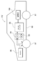
- FIG. 1 is a partially enlarged vertical cross-sectional view of a power supply device according to an embodiment of the present invention. It is a disassembled perspective view which shows the laminated structure of the battery cell of the battery laminated body shown in FIG. It is an expanded view of the bind bar of the power supply device shown in FIG. It is a principal part expansion perspective view of the bind bar of the power supply device shown in FIG. It is a block diagram which shows the example which mounts a power supply device in the hybrid car which drive
- a power supply device that exposes the entire bottom surface of the battery stack while fastening both sides of the battery stack with a large number of battery cells stacked with a bind bar is preferably a battery cell in a structure in which a cooling plate is disposed on the lower surface.
- each battery cell can be efficiently cooled by being thermally coupled to the cooling plate, and not only the cooling plate but also the structure in which the battery stack is mounted on the flat base plate and held on the bottom surface of the battery stack. It can be supported stably without holding both sides locally with the bind bar.
- the battery cell is also important to securely prevent the battery cell from being displaced by fastening the battery stack with a bind bar.
- the frequency of exposure to vibration and impact increases.
- a heavy battery stack in which a large number of battery cells are stacked has a negative effect that the greater the number of cells, that is, the longer the battery stack, the more easily the battery cells are vibrated up and down due to vibration or the like.
- the battery stack is laminated with an insulating material sandwiched between adjacent battery cells. However, if the battery cell is displaced and the insulating material is rubbed and damaged, the insulation breaks down and a large short battery flows. It can be a cause.
- the battery cell may be displaced and may be physically damaged to deteriorate electrical characteristics or shorten the life.
- the displacement of the battery cell can be reduced by tightening with a bind bar so that it is strongly pressed.
- a bind bar so that it is strongly pressed.
- the insulating material may be deformed so that the insulating state cannot be maintained, or the internal pressure of the battery cell is increased and gas is ejected.
- the battery cell is charged and discharged and generates heat.
- the amount of heat generated also increases.
- An efficient cooling structure is required in order to shorten the battery life when the battery cell becomes hot.
- the battery stack is placed on the cooling plate, and the bottom surface of the battery stack is fixed in a thermally coupled state with the upper surface of the cooling plate. In such a structure, it is important to efficiently thermally couple the bottom surface of the battery stack and the cooling plate.
- the conventional power supply device has a drawback that the bind bar limits the thermal coupling area between the cooling plate and the battery stack because the bind bar is disposed on a part of the bottom surface of the battery stack.
- the structure in which the bottom surface of the battery stack is thermally coupled to the cooling plate with the full width is ideal as a cooling structure, but has a drawback that it is difficult to hold the battery stack in a state in which the battery stack is not displaced by the bind bar. Therefore, it is important to study a structure that can reliably prevent the positional deviation of the battery cell while exposing the bottom surface of the stacked battery stack with the full width as a structure in which both sides of the battery stack are fastened with a bind bar. .
- the power supply device may be specified by the following configuration.
- the power supply device includes a battery stack 2 formed by stacking a plurality of battery cells 1, a pair of end plates 3 disposed at both ends of the battery stack 2, and battery cells 1 of the battery stack 2.
- a bind bar 4 extending in the stacking direction and having both ends connected to the end plate 3 is provided.
- the battery stack 2 has a quadrangular prism shape extending in the stacking direction of the battery cells 1, and includes an electrode surface 2A on which the electrodes of the battery cell 1 are arranged, a bottom surface 2B opposite to the electrode surface 2A, and a bind bar 4.
- the opposing side surface 2C formed is the four surrounding surfaces.
- an elastic sheet 6 that can be elastically deformed in the thickness direction is disposed between the bind bar 4 and the opposite side surface 2C of the battery stack 2 in a compressed state, and the elastic sheet 6 in the compressed state is the battery stack.
- the two opposing side surfaces 2C and the inner surface of the bind bar 4 are elastically held in a pressurized state.
- the elastic sheet 6 may be a rubber-like elastic sheet. Further, the elastic sheet 6 may be foamed rubber. This power supply device is characterized in that foamed rubber having a high frictional resistance is disposed between the battery laminate and the bind bar, so that the battery cells can be prevented from being displaced more reliably.
- the elastic sheet 6 may be a closed cell foam.
- the elastic sheet is a closed cell foam, even if condensed water generated in a bad external condition such as temperature and humidity is absorbed by the elastic sheet, the bubbles are independent. Since water is not connected inside, insulation between battery cells is ensured.
- the closed-cell foam is cushioned by the air contained in it, increasing the pressure applied to the battery stack and the binding bar to increase the frictional resistance, and the large frictional resistance ensures more accurate battery cell misalignment. Has features that can be prevented.
- the power supply device includes a cooling plate 7X that is disposed on the bottom surface 2B of the battery stack 2 and cools each battery cell 1, and the cooling plate 7X is disposed in a thermally coupled state over the entire width of the bottom surface 2B of the battery stack 2. May be. Since this power supply device can increase the thermal coupling area between the cooling plate and the battery stack, it has a feature that the battery cell can be efficiently cooled by the cooling plate. In addition, the contact area between the cooling plate and the battery cell is large, and the cooling plate does not support the bottom surface of the battery cell locally, but supports the entire surface with a wide area, so that the battery cell can be deformed or damaged by vibration or impact. Features that can be prevented are also realized.
- the power supply device may have a configuration in which the bind bar 4 has a ridge 44 extending in the stacking direction of the battery cells 1. Since this power supply device can improve the bending strength of the bind bar with the ridges provided on the bind bar, it is possible to reliably press the elastic sheet to the battery cell by suppressing the bind bar from spreading outward. For this reason, an elastic sheet can be reliably arrange
- the power supply device may be provided with the ridges 44 by pressing the bind bar 4 as a metal plate.
- the power supply device includes a main body portion 40 in which the bind bar 4 is disposed on the opposite side surface 2 ⁇ / b> C of the battery stack 2, and a fixing piece 41 connected to both ends of the main body portion 40 and fixed to the end plate 3.
- the protrusions 44 may be provided so as to extend from the main body portion 40 of the bind bar 4 to the fixed piece 41.
- the power supply device uses a bind bar 4 as a metal plate, a main body portion 40 disposed on the opposite side surface 2C of the battery stack 2, and a fixing piece 41 connected to both ends of the main body portion 40 and fixed to the end plate 3.
- a corner plate 42 connected to the edge of the main body 40 and the fixing piece 41, and the corner plate 42 is a metal main body corner plate 42 ⁇ / b> A continuous with the side edge of the main body 40, and the fixing piece 41.
- the metal corner plate 42A is bent at a right angle at the boundary with the main body portion 40
- the fixed corner plate 42B is bent at a right angle at the boundary with the fixed piece 41.
- the body corner plate 42 ⁇ / b> A and the fixed corner plate 42 ⁇ / b> B may be bent and fixed in a stacked state and disposed at a position facing the electrode surface 2 ⁇ / b> A of the battery stack 2.
- a corner plate is provided by effectively using a part of the metal plate serving as a bind bar, and the corner portion between the main body portion and the fixing piece is reinforced with the corner plate, and the main body portion and the fixing piece are provided.
- the bending strength of the boundary can be improved.
- the fixing piece connected to the main body portion at the corner portion having a strong bending strength has a feature that it can be securely fixed in close contact with the outer surface of the end plate even when a strong tensile force is applied.
- (Power supply device 100) 1 to 3 includes a pair of end plates 3 disposed on both end surfaces in the stacking direction of a battery stack 2 in which a plurality of battery cells 1 are stacked with insulating separators 5 interposed therebetween, and a battery.
- a bind bar 4 disposed on both side surfaces of the laminate 2 and having both ends connected to the end plate 3; an elastic sheet 6 sandwiched in a gap between the bind bar 4 and the battery laminate 2; 2 and a base plate 7 disposed on the bottom surface.
- the power supply apparatus 100 uses the base plate 7 as a cooling plate 7X.
- This power supply apparatus 100 can cool the battery cell 1 by the cooling plate 7X by thermally coupling the cooling plate 7X to each battery cell 1.
- the power supply device of the present invention is not necessarily specified as a structure in which the cooling plate is disposed on the bottom surface of the battery stack, and the base plate may be a planar plate material that is placed in a fixed position on the battery stack. it can.
- the battery stack 2 has a quadrangular prism shape in which a plurality of battery cells 1 are stacked and extend in the stacking direction of the battery cells 1.
- the battery stack 2 includes an electrode surface 2A on which the electrode of the battery cell 1 is disposed, a bottom surface 2B on the opposite side of the electrode surface 2A, and an opposing side surface 2C on which the bind bar 4 is disposed on four surrounding surfaces. It is a quadrangular prism.
- the power supply device 100 is mainly used in a posture in which the upper surface of the battery stack 2 is the electrode surface 2A and the lower surface is the bottom surface 2B. You can also.
- the battery cell 1 is a rectangular battery having an outer shape whose thickness is smaller than its width.
- the battery cell 1 is a lithium ion secondary battery.
- the battery cell 1 can use all the secondary batteries which can be charged / discharged, such as a nickel-hydrogen secondary battery, instead of a lithium ion secondary battery.
- a lithium ion secondary battery is used for the battery cell 1, there is an advantage that the charge capacity with respect to the volume and mass of the entire secondary battery can be increased.
- the battery cell 1 is provided with positive and negative electrode terminals 13 on a sealing plate 12 that closes the opening of the outer can 11.
- the electrode terminals 13 are connected to positive and negative electrode bodies (not shown) built in the outer can 11.
- the outer can 11 is a rectangular tube having a closed bottom and a wide surface on both sides facing each other, and opens upward in the figure.
- the outer can 11 having this shape is manufactured by pressing a metal plate such as aluminum or aluminum alloy.
- the opening of the outer can 11 is closed by laser welding with a flat sealing plate 12 obtained by pressing a metal plate.
- the sealing plate 12 is provided with a discharge valve 14 between a pair of electrode terminals 13.
- the discharge valve 14 is configured to open when the internal pressure of the outer can 11 rises to a predetermined value or more, and to release the internal gas. By opening the discharge valve 14, an increase in the internal pressure of the outer can 11 can be suppressed.
- the discharge valve 14 is preferably disposed approximately at the center in the longitudinal direction of the sealing plate 12. Thereby, even if the adjacent battery cells 1 are stacked in a posture reversed in the width direction, the discharge valve 14 can always be aligned at the center of the sealing plate 12.
- End plate 3 A pair of end plates 3 are arranged on both end surfaces of the battery stack 2 in which the battery cells 1 and the insulating separators 5 are alternately stacked, and the battery stack 2 is fastened in a pressurized state with the pair of end plates 3. Yes.
- the end plate 3 is made of a material that exhibits sufficient strength, for example, a metal such as aluminum (in this specification, aluminum is used to include an aluminum alloy), and can be made sufficiently strong while being reduced in weight.
- the end plate 3 has an outer shape substantially equal to the outer shape of the battery cell 1 or slightly larger than the battery cell 1 to fix the entire surface of both end faces of the battery stack 2 in a pressurized state.
- the power supply device 100 places the battery stack 2 on the base plate 7 and fixes it in place.
- the end plate 3 is provided with a fixing portion 30 on the outer surface for fixing the battery stack 2 to the base plate 7.
- the end plate 3 of FIG. 3 is a position away from the left and right centers on both sides, and is provided with a pair of fixed portions 30 integrally formed at the center in the vertical direction.
- the fixing portion 30 in FIG. 3 is in a block shape, and is provided with an insertion hole 32 through which a bolt (not shown) to be fixed to the base plate 7 passes vertically.
- the end plate 3 shown in the drawing is provided with a flange portion 31 that connects the pair of fixing portions 30 integrally formed at the upper and lower central portions of the fixing portion 30.
- the flange portion 31 has a plate shape that extends in the width direction of the end plate 3 and is positioned in a horizontal plane.
- the flange portion 31 serves as a handle when the power supply device 100 is lifted or transported, or serves as a locking portion for the lifting tool.
- the metal end plate 3 is manufactured by casting into a shape in which the pair of fixing portions 30 and the flange portion 31 are integrated, or the aluminum end plate is manufactured by casting or molding by aluminum die casting.
- the end plate can also be manufactured in a shape having a pair of fixed portions and flange portions by cutting a metal plate.
- the end plate may be a laminated structure of metal and plastic.
- the end plate 3 is provided with female screw holes 33 for bolting the bind bar 4 on both sides of the outer surface.
- the end plate of FIG. 1 is provided with two female screw holes 33 because the fixing pieces 41 connected to both ends of the main body portion 40 of the bind bar 4 are fixed with two bolts 9.
- the female screw hole 33 is provided at a fixing position of the bolt 9 so as to extend from the surface toward the back side.
- the bind bar 4 has a shape in which fixing pieces 41 bent at a right angle are connected to both ends of the main body 40 extending in the stacking direction of the battery cells 1, and the fixing pieces 41 are fixed to the outer surface of the end plate 3.
- the battery stack 2 is held in a pressurized state between the pair of end plates 3.
- the bind bar 4 connects the pair of end plates 3 by disposing the main body 40 on the opposite side surface 2 ⁇ / b> C of the battery stack 2 and disposing the fixing piece 41 on the outer surface of the end plate 3.
- the fixing piece 41 is provided with two bolt holes 43 that are inserted into the female screw holes 33 of the end plate 3 so as to pass through the bolts 9.
- the bind bar 4 has a predetermined thickness and is manufactured by cutting a metal plate such as high-tensile steel having sufficient tensile strength into a predetermined shape and then bending it.
- the ridges 44 are provided by pressing a metal plate.
- the bind bar 4 shown in the figure is provided with a ridge 44 extending continuously from the main body 40 to the fixed piece 41.
- the ridge 44 has a shape protruding outward and is provided in an intermediate portion in the width direction.
- the ridges 44 in the figure have a cross-sectional shape that is curved with a predetermined radius of curvature.
- the bind bar 4 shown in the figure is provided with one row of ridges 44 in the middle, but it is also possible to provide a plurality of rows of ridges 44.
- the bind bar 4 provided with the protruding ridges 44 protruding outward can widen the gap with the battery laminate 2 and sandwich the thick elastic sheet 6 inside the ridges 44.
- the thick elastic sheet 6 is sandwiched between the battery stack 2 and the bind bar 4 in a compressed state, and can press the opposing side surface 2C of the battery stack 2 without difficulty while ensuring a predetermined pressure or more.
- An elastic sheet 6 to be described later is sandwiched between the battery stack 2 and the bind bar 4 to increase the frictional resistance between the battery cell 1 and the bind bar 4, and thus the positional deviation of the battery cell 1, particularly the battery.
- the cell 1 is prevented from moving to the bottom surface 2B side.
- the pressing force between the elastic sheet 6, the battery stack 2 and the bind bar 4 is enhanced. Since the frictional resistance increases in proportion to the pressing force, the structure capable of strengthening the pressing force can increase the frictional resistance of the elastic sheet 6 and effectively suppress the displacement of each battery cell 1.
- the bind bar 4 includes a main body portion 40 disposed on the opposite side surface 2C of the battery stack 2, a fixing piece 41 connected to both ends of the main body portion 40 and fixed to the end plate 3, and the main body portion 40 fixed.
- the metal plate is cut into an outer shape in which the corner plate 42 connected to the edge of the piece 41 is continuous.
- FIG. 4 is a diagram in which a metal plate to be the bind bar 4 is developed in a planar shape.
- the metal plate used as the bind bar 4 shown in this figure has a fixing piece 41 connected to both ends in the longitudinal direction of the main body 40, and one side (upper in the figure) of both ends in the longitudinal direction of the main body 40.
- the main body corner plate 42 ⁇ / b> A is connected, and the fixed corner plate 42 ⁇ / b> B is connected to one end in the longitudinal direction of the fixed piece 41.
- the main body corner plate 42A and the fixed corner plate 42B are bent at a right angle at the boundary between the main body portion 40 and the fixed piece 41, and further at a right angle at the boundary between the main body portion 40 and the main body corner plate 42A. Further, it is bent at a right angle at the boundary between the fixed piece 41 and the fixed corner plate 42B, and is arranged at a position where they are stacked.
- the main body corner plate 42 ⁇ / b> A and the fixed corner plate 42 ⁇ / b> B are stacked on each other and fixed by a method such as welding to form the corner plate 42.
- the corner plate 42 in which the main body corner plate 42A and the fixed corner plate 42B are laminated and fixed has sufficient strength in a two-layer laminated structure, and two orthogonal sides are connected to the main body portion 40 and the fixing piece 41. Then, the fixing piece 41 is firmly connected to the main body 40 with a sufficient bending strength. Since the main body corner plate 42A and the fixed corner plate 42B are provided in the process of cutting one metal plate, it is not necessary to use a dedicated metal plate, and the binding bar 4 does not increase the material cost and the manufacturing cost. Reinforce.
- the metal binding bar 4 is preferably insulated from the battery stack 2 while being disposed on the opposite side surface 2C of the battery stack 2. 1 and 2, an insulating sheet 8 is disposed between the opposing side surface 2C of the battery stack 2 and the bind bar 4 to insulate the battery stack 2 and the bind bar 4 from each other. .
- the insulating sheet 8 is, for example, a sheet shape along the inner side surface of the main body 40 of the bind bar 4, and is bonded to the inner surface of the main body 40 and disposed at a fixed position.
- the bind bar 4 is fixed to the end plate 3 and exposes the bottom surface 2B of the battery stack 2 in full width. Therefore, the main body portion 40 of the bind bar 4 does not have a portion that covers the bottom surface 2B of the battery stack 2 and is disposed only on the surface facing the facing side surface 2C of the battery stack 2.
- the power supply device 100 is configured to fix the bind bar 4 to the end plate 3, and to the lower side of the battery cell 1 with the bind bar 4 while the pair of end plates 3 hold the battery stack 2 in a pressurized state. Therefore, the battery cell 1 may be displaced. In this state, in order to prevent the displacement of the battery cell 1, the power supply device 100 of FIGS. 1 and 2 sandwiches the elastic sheet 6 between the opposite side surface 2 ⁇ / b> C of the battery stack 2 and the inner surface of the bind bar 4. It is out.
- the elastic sheet 6 is a sheet that can be elastically deformed in the thickness direction.
- the elastic sheet 6 that can be compressed in the thickness direction is a rubber-like elastic sheet.
- the rubber-like elastic sheet is foamed rubber or synthetic resin foam. Since the foamed rubber has a large frictional resistance, displacement of the battery cell 1 can be more effectively prevented. Synthetic resin foams are characterized by being inexpensively mass-produced.
- the foamed elastic sheet 6 is characterized in that the elasticity can be controlled by the foaming rate.
- the foam elastic sheet 6 is preferably a closed-cell foam. The closed-cell foam prevents water from passing through because the foamed bubbles are independent, so even if water is generated near the surface of the elastic sheet, water is not connected inside the elastic sheet.
- the elastic sheet 6 is sandwiched between the battery stack 2 and the bind bar 4 in a compressed state, and is disposed in a state of pressing the battery stack 2 and the bind bar 4.
- the elastic sheet 6 sandwiched in a compressed state is thicker than the gap between the battery stack 2 and the bind bar 4, for example, 30% thicker than the gap between the battery stack 2 and the bind bar 4, preferably more than 50%. Thick, more preferably greater than 80%.
- the gap between the battery stack 2 and the bind bar 4 is, for example, thicker than 0.3 mm, preferably 0 so that the elastic sheet 6 is placed in a compressed state and the elastic sheet 6 is pressed at a predetermined pressure or higher. Thicker than 5 mm.
- the thickness of the elastic sheet 6 is set in the above-mentioned range in consideration of the gap between the battery stack 2 and the bind bar 4, but the thickness varies depending on the elastic modulus. In consideration of the gap, the elastic modulus, and the stacking pressure of the stacked battery cells 1 also affects the positional deviation. Is set.
- the power supply device 100 In the state of use, the power supply device 100 is provided with a base plate 7 and the like on the bottom surface 2B so that the base plate 7 prevents a downward displacement of the battery cell 1.
- the power supply apparatus 100 needs to prevent the positional deviation of the battery cell 1 in the assembly process until the base plate 7 is fixed.
- the power supply device 100 is configured such that the elastic sheet 6 prevents the displacement of the battery cell 1 during a period until the base plate 7 is fixed. Specifically, the elastic sheet 6 held in a compressed state reliably presses the battery cell 1 and the bind bar 4 with a sufficient pressing force in the assembling process to reliably prevent the positional deviation of the battery cell 1.
- the base plate 7 Even if the compressive force is reduced due to deterioration over time, when the base plate 7 is fixed, the battery cell 1 is prevented from being displaced by the base plate 7. Therefore, even if the elastic sheet 6 deteriorates, the battery cell 1 Will not be displaced. Even if the elastic sheet 6 deteriorates and the pressing force decreases, as long as the elastic sheet 6 presses the battery stack 2 and the bind bar 4, the displacement of the battery cell 1 is prevented by the frictional resistance of the elastic sheet 6. With the base plate 7 fixed to the bottom surface 2B, the base plate 7 prevents the battery cell 1 from being displaced.
- the battery cell 1 whose displacement is prevented by the frictional resistance of the elastic sheet 6 is subjected to vibration or impact in use and the battery cell 1 vibrates.
- the cooling plate 7X is fixed to the bottom surface 2B of the battery stack 2 in a thermally coupled state.
- the cooling plate 7X is fixed to the fixing portion 30 of the end plate 3.
- the cooling plate 7X is provided with a refrigerant path (not shown) inside.
- the cooling plate 7X is cooled by circulating a cooling refrigerant in the refrigerant path.
- the cooling plate 7X that circulates the refrigerant in the refrigerant path can be efficiently cooled.
- the cooling plate may be structured to be cooled by providing heat radiation fins on the surface.
- a heat conductive paste is applied or a heat conductive sheet is sandwiched between the cooling plate 7X and a preferable heat coupling state.
- the battery stack 2 having no insulating layer on the bottom surface 2B is provided with an insulating sheet between the cooling plate 7X to insulate the battery stack 2 from the cooling plate 7X.
- the above power supply apparatus is most suitable for a vehicle power supply apparatus that supplies electric power to a motor that drives an electric vehicle.
- a vehicle power supply apparatus that supplies electric power to a motor that drives an electric vehicle.
- an electric vehicle equipped with a power supply device an electric vehicle such as a hybrid vehicle or a plug-in hybrid vehicle that runs with both an engine and a motor, or an electric vehicle that runs only with a motor can be used, and used as a power source for these electric vehicles. Is done.
- FIG. 5 shows an example in which a power supply device is mounted on a hybrid vehicle that travels with both an engine and a motor.
- a vehicle HV equipped with the power supply device shown in FIG. 1 includes a vehicle main body 90, an engine 96 and a traveling motor 93 that travel the vehicle main body 90, a power supply device 100 that supplies power to the motor 93, A generator 94 that charges the battery, and a wheel 97 that is driven by a motor 93 and an engine 96 to run the vehicle main body 90 are provided.
- the power supply apparatus 100 is connected to a motor 93 and a generator 94 via a DC / AC inverter 95.
- the vehicle HV travels by both the motor 93 and the engine 96 while charging / discharging the battery of the power supply device 100.
- the motor 93 is driven to drive the vehicle when the engine efficiency is low, for example, during acceleration or low-speed driving.
- the motor 93 is driven by power supplied from the power supply device 100.
- the generator 94 is driven by the engine 96 or is driven by regenerative braking when the vehicle is braked to charge the battery of the power supply device 100.
- FIG. 6 shows an example in which a power supply device is mounted on an electric vehicle that runs only with a motor.
- a vehicle EV equipped with the power supply device shown in this figure includes a vehicle main body 90, a motor 93 for running the vehicle main body 90, a power supply device 100 that supplies power to the motor 93, and a battery of the power supply device 100. And a wheel 97 that is driven by a motor 93 and travels the vehicle main body 90.
- the motor 93 is driven by power supplied from the power supply device 100.
- the generator 94 is driven by energy when regeneratively braking the vehicle EV and charges the battery of the power supply device 100.
- the power supply device according to the present invention and a vehicle including the power supply device can be suitably used as a power supply device for a plug-in hybrid electric vehicle, a hybrid electric vehicle, an electric vehicle, or the like that can switch between the EV traveling mode and the HEV traveling mode.
- SYMBOLS 100 Power supply device, 1 ... Battery cell, 2 ... Battery laminated body, 2A ... Electrode surface, 2B ... Bottom surface, 2C ... Opposite side surface, 3 ... End plate, 4 ... Bind bar, 5 ... Insulating separator, 6 ... Elastic sheet, DESCRIPTION OF SYMBOLS 7 ... Base plate, 7X ... Cooling plate, 8 ... Insulating sheet, 9 ... Bolt, 11 ... Exterior can, 12 ... Sealing plate, 13 ... Electrode terminal, 14 ... Discharge valve, 30 ... Fixing part, 31 ... Flange part, 32 ... Insertion hole 33 ... Female screw hole 40 ... Body part 41 ... Fixed piece 42 ...
- Corner plate 42A Body corner plate 42B . Fixed corner plate 43 ... Bolt hole 44 ... Projection strip 90 ... Vehicle body 93 ... Motor, 94 ... Generator, 95 ... DC / AC inverter, 96 ... Engine, 97 ... Wheel, HV ... Vehicle, EV ... Vehicle
Landscapes
- Engineering & Computer Science (AREA)
- Chemical & Material Sciences (AREA)
- Chemical Kinetics & Catalysis (AREA)
- Electrochemistry (AREA)
- General Chemical & Material Sciences (AREA)
- Manufacturing & Machinery (AREA)
- Mechanical Engineering (AREA)
- Transportation (AREA)
- Sustainable Energy (AREA)
- Power Engineering (AREA)
- Sustainable Development (AREA)
- Life Sciences & Earth Sciences (AREA)
- Aviation & Aerospace Engineering (AREA)
- Combustion & Propulsion (AREA)
- Battery Mounting, Suspending (AREA)
- Secondary Cells (AREA)
Abstract
Afin d'empêcher de manière fiable un écart de position d'une cellule de batterie tout en exposant toute la largeur de la surface inférieure d'un corps d'empilement de batterie, dans ce dispositif d'alimentation électrique : une paire de plaques d'extrémité (3) sont disposées sur les deux surfaces d'extrémité du corps d'empilement de batterie (2) dans lequel une pluralité de cellules de batterie (1) sont empilées ; les plaques d'extrémité (3) sont reliées pour lier des barres (4) et le corps d'empilement de batterie (2) est maintenu en étant pris en sandwich entre les plaques d'extrémité (3); et des feuilles élastiques (6) qui sont élastiquement déformables dans la direction de l'épaisseur sont respectivement agencées dans un état comprimé entre les barres de liaison (4) et en regard de la surface latérale (2C) du corps d'empilement de batterie (2), et ainsi, les feuilles élastiques à l'état comprimé (6) sont maintenues élastiquement par le corps d'empilement de batterie (2) et les barres de liaison (4) dans un état comprimé.
Priority Applications (4)
| Application Number | Priority Date | Filing Date | Title |
|---|---|---|---|
| US16/982,282 US11479129B2 (en) | 2018-03-30 | 2018-11-16 | Power supply device and electric vehicle provided with power supply device |
| JP2020509608A JP7207814B2 (ja) | 2018-03-30 | 2018-11-16 | 電源装置と電源装置を備える電動車両 |
| EP18911500.9A EP3780138A4 (fr) | 2018-03-30 | 2018-11-16 | Dispositif d'alimentation électrique et véhicule électrique équipé d'un dispositif d'alimentation électrique |
| CN201880092171.8A CN111937179B (zh) | 2018-03-30 | 2018-11-16 | 电源装置和具有电源装置的电动车辆 |
Applications Claiming Priority (2)
| Application Number | Priority Date | Filing Date | Title |
|---|---|---|---|
| JP2018-069573 | 2018-03-30 | ||
| JP2018069573 | 2018-03-30 |
Publications (1)
| Publication Number | Publication Date |
|---|---|
| WO2019187315A1 true WO2019187315A1 (fr) | 2019-10-03 |
Family
ID=68061069
Family Applications (1)
| Application Number | Title | Priority Date | Filing Date |
|---|---|---|---|
| PCT/JP2018/042379 WO2019187315A1 (fr) | 2018-03-30 | 2018-11-16 | Dispositif d'alimentation électrique et véhicule électrique équipé d'un dispositif d'alimentation électrique |
Country Status (5)
| Country | Link |
|---|---|
| US (1) | US11479129B2 (fr) |
| EP (1) | EP3780138A4 (fr) |
| JP (1) | JP7207814B2 (fr) |
| CN (1) | CN111937179B (fr) |
| WO (1) | WO2019187315A1 (fr) |
Cited By (3)
| Publication number | Priority date | Publication date | Assignee | Title |
|---|---|---|---|---|
| JP2021533550A (ja) * | 2019-03-19 | 2021-12-02 | エルジー・ケム・リミテッド | 長さが延びた絶縁パッドを備えるバッテリーモジュール、それを含むバッテリーパック及び自動車 |
| CN114402477A (zh) * | 2020-01-03 | 2022-04-26 | 株式会社Lg新能源 | 具有改进的联接结构的电池组及包括该电池组的车辆 |
| JP2023075547A (ja) * | 2021-11-19 | 2023-05-31 | プライムプラネットエナジー&ソリューションズ株式会社 | 電池モジュール |
Families Citing this family (6)
| Publication number | Priority date | Publication date | Assignee | Title |
|---|---|---|---|---|
| US9893384B2 (en) * | 2014-05-18 | 2018-02-13 | Black & Decker Inc. | Transport system for convertible battery pack |
| WO2019245028A1 (fr) * | 2018-06-22 | 2019-12-26 | 株式会社Gsユアサ | Dispositif de stockage d'énergie |
| KR102646202B1 (ko) | 2020-10-19 | 2024-03-12 | 지앙수 컨템포러리 엠퍼렉스 테크놀로지 리미티드 | 배터리, 전기 장치, 배터리를 제조하는 방법과 장치 |
| WO2022082397A1 (fr) | 2020-10-19 | 2022-04-28 | 江苏时代新能源科技有限公司 | Batterie, appareil électrique, et procédé et dispositif de préparation de batterie |
| JP7457872B2 (ja) * | 2020-10-19 | 2024-03-28 | ジアンス・コンテンポラリー・アンプレックス・テクノロジー・リミテッド | 電池、電気装置、電池の製造方法および装置 |
| US11850969B1 (en) | 2022-08-23 | 2023-12-26 | Intercontinental Mobility Company | Portable motorized vehicles |
Citations (3)
| Publication number | Priority date | Publication date | Assignee | Title |
|---|---|---|---|---|
| JP2010086887A (ja) | 2008-10-02 | 2010-04-15 | Toshiba Corp | バッテリモジュール |
| JP2011171029A (ja) * | 2010-02-17 | 2011-09-01 | Sanyo Electric Co Ltd | 電池モジュール |
| JP2012094456A (ja) | 2010-10-28 | 2012-05-17 | Sanyo Electric Co Ltd | 電源装置 |
Family Cites Families (31)
| Publication number | Priority date | Publication date | Assignee | Title |
|---|---|---|---|---|
| US3278339A (en) * | 1964-04-20 | 1966-10-11 | Union Carbide Corp | Primary dry cells |
| FI49090C (fi) * | 1972-11-10 | 1975-03-10 | Pentti Juuse Tamminen | Galvaaninen levykeparisto. |
| US4950561A (en) * | 1989-06-29 | 1990-08-21 | Eltech Systems Corporation | Metal-air battery with easily removable anodes |
| US5264305A (en) * | 1991-05-03 | 1993-11-23 | Energy Research Corporation | Zinc secondary battery having bipolar plate construction with horizontally disposed battery components |
| JP3180487B2 (ja) * | 1993-01-07 | 2001-06-25 | 凸版印刷株式会社 | 巻取り繋止片付きのラップフィルム収容紙箱 |
| US7195840B2 (en) * | 2001-07-13 | 2007-03-27 | Kaun Thomas D | Cell structure for electrochemical devices and method of making same |
| JP5405858B2 (ja) * | 2008-04-14 | 2014-02-05 | 日産自動車株式会社 | 組電池、組電池の製造方法および組電池を搭載した車両 |
| US20120121951A1 (en) * | 2010-11-16 | 2012-05-17 | Hall David R | Battery with an Internal Heating Element |
| JP5734704B2 (ja) * | 2011-02-28 | 2015-06-17 | 三洋電機株式会社 | 電源装置及び電源装置を備える車両 |
| WO2012133708A1 (fr) * | 2011-03-31 | 2012-10-04 | 三洋電機株式会社 | Dispositif de source d'alimentation et véhicule comportant un dispositif de source d'alimentation |
| JP2013012441A (ja) * | 2011-06-30 | 2013-01-17 | Sanyo Electric Co Ltd | 電源装置及び電源装置を備える車両 |
| US20140220391A1 (en) * | 2011-08-26 | 2014-08-07 | Sanyo Electric Co., Ltd., | Power source apparatus, and vehicle and power storage device equipped with that power source apparatus |
| JP5624015B2 (ja) * | 2011-12-09 | 2014-11-12 | 本田技研工業株式会社 | バッテリの冷却装置 |
| JP2015111493A (ja) * | 2012-03-28 | 2015-06-18 | 三洋電機株式会社 | 電源装置及びこれを備える車両並びに蓄電装置 |
| JP2015187911A (ja) * | 2012-08-09 | 2015-10-29 | 三洋電機株式会社 | 車両用のバッテリシステム及びバッテリシステムを備える電動車両 |
| WO2014034079A1 (fr) * | 2012-08-30 | 2014-03-06 | 三洋電機株式会社 | Dispositif de source d'énergie, véhicule équipé d'un dispositif de source d'énergie, et dispositif de stockage d'énergie |
| JP6224321B2 (ja) * | 2013-01-11 | 2017-11-01 | フタバ産業株式会社 | 組電池の拘束具、組電池の拘束部材、バッテリ |
| EP2958165B1 (fr) * | 2013-02-15 | 2017-09-20 | Hitachi Automotive Systems, Ltd. | Module de batterie secondaire |
| CN109148935A (zh) * | 2013-03-14 | 2019-01-04 | 新强能电池公司 | 用于电化学电池堆的夹持设备 |
| JP6097607B2 (ja) * | 2013-03-19 | 2017-03-15 | 株式会社Gsユアサ | 蓄電装置及び蓄電装置ユニット |
| US10090494B2 (en) * | 2014-03-31 | 2018-10-02 | Ford Global Technologies, Llc | Support structure for battery cells within a traction battery assembly |
| JP6172037B2 (ja) * | 2014-04-23 | 2017-08-02 | トヨタ自動車株式会社 | 蓄電装置 |
| JP6254904B2 (ja) * | 2014-05-26 | 2017-12-27 | 本田技研工業株式会社 | 蓄電モジュール及びその固定構造 |
| CN105322109B (zh) * | 2014-07-30 | 2020-01-14 | 株式会社杰士汤浅国际 | 蓄电装置 |
| JP6305260B2 (ja) * | 2014-07-30 | 2018-04-04 | 株式会社Gsユアサ | 蓄電装置 |
| JP6338974B2 (ja) * | 2014-08-27 | 2018-06-06 | 三洋電機株式会社 | バッテリシステム |
| JP6303951B2 (ja) * | 2014-09-22 | 2018-04-04 | 株式会社豊田自動織機 | 蓄電モジュール |
| WO2016136248A1 (fr) * | 2015-02-27 | 2016-09-01 | 三洋電機株式会社 | Dispositif d'alimentation électrique, et véhicule équipé de celui-ci |
| US10727549B2 (en) * | 2015-04-28 | 2020-07-28 | Sanyo Electric Co., Ltd. | Power supply device and vehicle provided therewith |
| KR101861429B1 (ko) * | 2016-06-08 | 2018-05-25 | 엘지전자 주식회사 | 배터리 팩 |
| JP6460066B2 (ja) * | 2016-08-25 | 2019-01-30 | トヨタ自動車株式会社 | 電池パック |
-
2018
- 2018-11-16 WO PCT/JP2018/042379 patent/WO2019187315A1/fr active Application Filing
- 2018-11-16 CN CN201880092171.8A patent/CN111937179B/zh active Active
- 2018-11-16 JP JP2020509608A patent/JP7207814B2/ja active Active
- 2018-11-16 EP EP18911500.9A patent/EP3780138A4/fr active Pending
- 2018-11-16 US US16/982,282 patent/US11479129B2/en active Active
Patent Citations (3)
| Publication number | Priority date | Publication date | Assignee | Title |
|---|---|---|---|---|
| JP2010086887A (ja) | 2008-10-02 | 2010-04-15 | Toshiba Corp | バッテリモジュール |
| JP2011171029A (ja) * | 2010-02-17 | 2011-09-01 | Sanyo Electric Co Ltd | 電池モジュール |
| JP2012094456A (ja) | 2010-10-28 | 2012-05-17 | Sanyo Electric Co Ltd | 電源装置 |
Non-Patent Citations (1)
| Title |
|---|
| See also references of EP3780138A4 |
Cited By (6)
| Publication number | Priority date | Publication date | Assignee | Title |
|---|---|---|---|---|
| JP2021533550A (ja) * | 2019-03-19 | 2021-12-02 | エルジー・ケム・リミテッド | 長さが延びた絶縁パッドを備えるバッテリーモジュール、それを含むバッテリーパック及び自動車 |
| JP7142765B2 (ja) | 2019-03-19 | 2022-09-27 | エルジー エナジー ソリューション リミテッド | 長さが延びた絶縁パッドを備えるバッテリーモジュール、それを含むバッテリーパック及び自動車 |
| CN114402477A (zh) * | 2020-01-03 | 2022-04-26 | 株式会社Lg新能源 | 具有改进的联接结构的电池组及包括该电池组的车辆 |
| EP4024578A4 (fr) * | 2020-01-03 | 2023-10-18 | Lg Energy Solution, Ltd. | Bloc-batterie ayant une structure de couplage améliorée et véhicule le comprenant |
| JP2023075547A (ja) * | 2021-11-19 | 2023-05-31 | プライムプラネットエナジー&ソリューションズ株式会社 | 電池モジュール |
| JP7488244B2 (ja) | 2021-11-19 | 2024-05-21 | プライムプラネットエナジー&ソリューションズ株式会社 | 電池モジュール |
Also Published As
| Publication number | Publication date |
|---|---|
| EP3780138A4 (fr) | 2021-04-21 |
| US11479129B2 (en) | 2022-10-25 |
| CN111937179A (zh) | 2020-11-13 |
| CN111937179B (zh) | 2023-01-03 |
| JP7207814B2 (ja) | 2023-01-18 |
| US20210016668A1 (en) | 2021-01-21 |
| EP3780138A1 (fr) | 2021-02-17 |
| JPWO2019187315A1 (ja) | 2021-03-25 |
Similar Documents
| Publication | Publication Date | Title |
|---|---|---|
| WO2019187315A1 (fr) | Dispositif d'alimentation électrique et véhicule électrique équipé d'un dispositif d'alimentation électrique | |
| US10727549B2 (en) | Power supply device and vehicle provided therewith | |
| JP7284710B2 (ja) | 電源装置及び電源装置を備える車両並びに蓄電装置 | |
| JP6073583B2 (ja) | 電源装置及びこの電源装置を備える車両並びに蓄電装置 | |
| CN107210397B (zh) | 电源装置及具有电源装置的车辆 | |
| CN107112461B (zh) | 包括具有夹持部的盒的电池模块 | |
| JP5595871B2 (ja) | 電源装置 | |
| WO2014024432A1 (fr) | Système de batterie pour véhicule, et véhicule électrique équipé de celui-ci | |
| JP6184959B2 (ja) | バッテリシステム及びバッテリシステムを備える車両並びに蓄電装置 | |
| KR101547814B1 (ko) | 간접 공냉 구조를 포함하는 전지모듈 | |
| JP7187463B2 (ja) | 電池モジュール及びこれを装備する車両 | |
| WO2014034107A1 (fr) | Dispositif de source d'énergie, véhicule électrique équipé d'un dispositif de source d'énergie, et dispositif de stockage d'énergie | |
| JP2011023302A (ja) | 組電池及びこれを備える車両並びに組電池用のバインドバー | |
| JP2012160347A (ja) | 電源装置及び電源装置を備える車両 | |
| US20200358127A1 (en) | Power supply device, vehicle provided with power supply device, and power storage device | |
| WO2019031169A1 (fr) | Module de batterie et véhicule équipé de celui-ci | |
| KR101799565B1 (ko) | 안전성이 향상된 전지팩 | |
| WO2019021778A1 (fr) | Module de batterie et véhicule équipé de celui-ci | |
| WO2020059296A1 (fr) | Dispositif d'alimentation électrique, véhicule comportant un dispositif d'alimentation électrique, et dispositif de stockage d'énergie | |
| WO2019187314A1 (fr) | Dispositif d'alimentation électrique et véhicule équipé d'un dispositif d'alimentation électrique | |
| CN112514146B (zh) | 电源装置、具有该电源装置的车辆以及缓冲体 | |
| JP7083773B2 (ja) | 電池モジュール | |
| JP2020184405A (ja) | 電池モジュール及びこれを装備する車両 | |
| WO2021157139A1 (fr) | Dispositif d'alimentation électrique, véhicule électrique l'utilisant et dispositif de stockage d'énergie | |
| JP7286668B2 (ja) | バッテリシステムとバッテリシステムを備える車両及び蓄電装置 |
Legal Events
| Date | Code | Title | Description |
|---|---|---|---|
| 121 | Ep: the epo has been informed by wipo that ep was designated in this application |
Ref document number: 18911500 Country of ref document: EP Kind code of ref document: A1 |
|
| ENP | Entry into the national phase |
Ref document number: 2020509608 Country of ref document: JP Kind code of ref document: A |
|
| WWE | Wipo information: entry into national phase |
Ref document number: 2018911500 Country of ref document: EP |